FNC-0115 - Network adapter LEVELONE - Free user manual and instructions
Find the device manual for free FNC-0115 LEVELONE in PDF.

User questions about FNC-0115 LEVELONE
0 question about this device. Answer the ones you know or ask your own.
Ask a new question about this device
Download the instructions for your Network adapter in PDF format for free! Find your manual FNC-0115 - LEVELONE and take your electronic device back in hand. On this page are published all the documents necessary for the use of your device. FNC-0115 by LEVELONE.
USER MANUAL FNC-0115 LEVELONE
text_image
level® oneFNC / GNC Quick Installation Guide
CAUTION: Turn off and unplug the power before removing the computer's cover. Failure to do so could endanger you and may damage the adapter or computer.
- Turn off the computer and unplug the power cord. For Hot Plug servers, see your server documentation first.
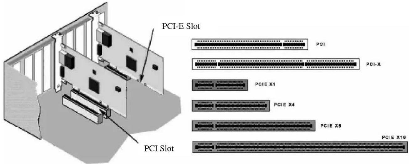
- Remove the cover bracket from a PCI-Express slot (v1.0a or newer) or a PCI (2.2 or later) slot. If you have configuration problems, see your computer's documentation to determine if the PCI-Express or PCI slots are bus master-enabled.
- Optional step for low profile capable models:
If you need to install the adapter in a low profile PCI-Express or PCI chassis, first replace the adapter standard bracket with the supplied low profile bracket. To remove existing bracket, unscrew the two screws as shown at right and then pull bracket off. Reverse the process to attach the low profile bracket. See the User's Guide (step 8) for complete instructions.
- Firmly insert the adapter into the selected slot. Push down to ensure the adapter is fully seated. If you install the adapter in a PCI-Express or PCI slot, make sure the exposed end of the connector does not touch any part of the motherboard. Secure the bracket to the chassis.
text_image
PCI-E Slot PCI PCI-X PCIE X1 PCIE X4 PCIE X8 PCIE X16 PCI Slot- Replace the computer cover and plug in the power cord.
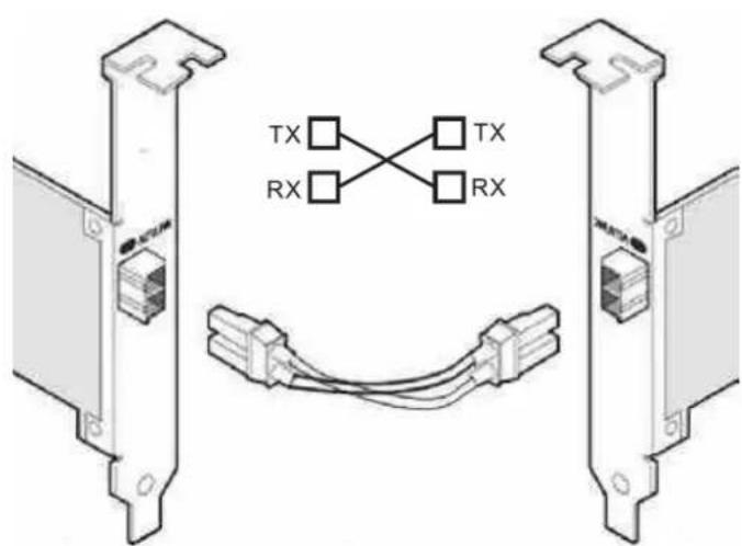
- Connect the network cable Copper Modles

text_image
Single-Port Models Dual-Port Models Quad-Port Modelsa. For 10Gbps operation(10GBase-T), use category 6 or better (must be 4-pair wiring with different pitches
b. Insert the twisted pair, RJ45 network connector as shown.
c. For 1000Mbps operation(1000BaseT), use Category 5 or better (must be 4-pair wiring). Make sure you use Category 5 cable that complies with the TIA-568 wiring specification.
d. For 100Mbps operation(100BaseTX), use Category 5 wiring or better.
Length is limited to 100 meters.
The adapter must be connected to a compatible link partner that has the same configuration.
Fiber Models
a. For fiber adapters, remove and save the fiber optic connector cover. Insert a matching fiber optic connector into the ports on the adapter as shown. Note: For LC adapters, converter patch cables are available to allow plugging into an SC type connector.
b. The SX type adapters must use SX compatible cabling (see table showing maximum reach) and the LX type adapter must use LX compatible cabling. Cabling and adapter types cannot be mixed. Note: the LX adapter has LX stamped on the bracket to identify it. See the Use's Guide on the CD for more information on cable type
| Fiber Cable Type | MM 62.5u | MM 50u | SM 9.0u |
| 10GBase-SR Type (850nm) | N/A | 300M | N/A |
| 10GBase-LR Type (1310nm) | N/A | N/A | 10KM |
| 1000Base-SX Type (850nm) | 275M | 550M | N/A |
| 1000Base-LX Type Adapter(1310nm) | N/A | N/A | 10KM |
| 100Base-SX Type (1310nm) | 2KM | 2KM | N/A |
| 100Base-LX Type (1310nm) | N/A | N/A | 20KM |
c. Most connectors and ports are keyed for proper orientation. If the cable you are using is not keyed, check to be sure the connector is oriented properly.
d. The adapter must be connected to a compatible link partner, or an IEEE 802.3z- compliant gigabit switch.
Optical fiber connection diagram
text_image
TX RX TX RXSingle-port fiber adapter with LC connector

natural_image
Technical line drawing of a computer RAM module with connector and cable (no text or symbols)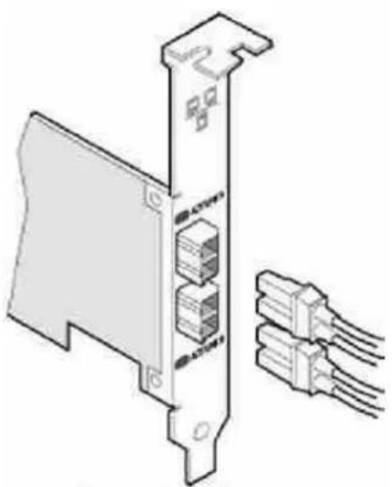
natural_image
Diagram of a computer RAM module with connectors and memory slots (no text or symbols)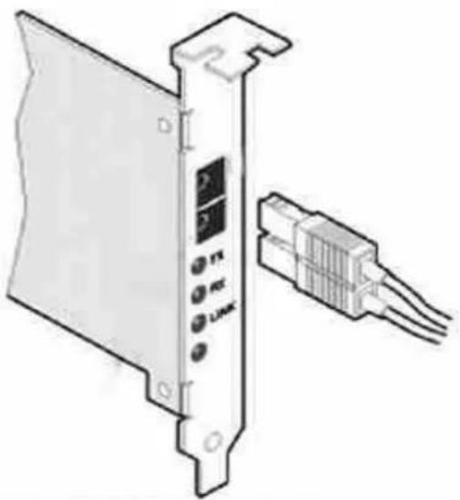
natural_image
Diagram of a device panel with labeled ports and connectors, showing internal components without any text or symbols.- Install the adapter drivers
a. Star the computer. Note that you must have administrative rights to the operating system to install the drivers.
b. Windows*2000, XP, Windows 7, Windows 8, Vista* and Server 2003: The adapter is detected and Windows either installs a resident driver or starts the Found New Hardware 01 wizard. If a resident driver installs (wizard does not appear), update the driver by inserting the covermouted CD. See the full User's Guide for detailed instructions (step 8).
c. Windows NT4.0, Linux, NetWare*, UnixWare, *FreeBSD, and other operating systems: Refer to the User's Guide on the CD (step 8).
8.User's Guide
The full User's Guide is located on the covermouted CD. Use your web browser to view or print topics in the User's Guide. The guide covers configuration, topics on features, additional operating systems, troubleshooting information, and support resources. To view the guide, put the CD in your drive and simply open the index.htm file in the Manual folder on the CD.
