RSC-112 - Pregnant QSC - Free user manual and instructions
Find the device manual for free RSC-112 QSC in PDF.

User questions about RSC-112 QSC
0 question about this device. Answer the ones you know or ask your own.
Ask a new question about this device
Download the instructions for your Pregnant in PDF format for free! Find your manual RSC-112 - QSC and take your electronic device back in hand. On this page are published all the documents necessary for the use of your device. RSC-112 by QSC.
USER MANUAL RSC-112 QSC
Reference Monitor System
User Guide
QSC™
RSC-112 3-way Screen Channel Loudspeaker
RSB-212 Subwoofer
RBK12 Baffle Wing Kit (each kit contains two baffle wings)
natural_image
Technical line drawing of a multi-tiered speaker chamber with visible speakers, doors, and wiring (no text or symbols)TD-000414-00-B
*TD-000414-00*

EXPLANATION OF TERMS AND SYMBOLS
The term "WARNING!" indicates instructions regarding personal safety. If the instructions are not followed the result may be bodily injury or death. The term "CAUTION!" indicates instructions regarding possible damage to physical equipment. If these instructions are not followed, it may result in damage to the equipment that may not be covered under the warranty.
The term "IMPORTANT!" indicates instructions or information that are vital to the successful completion of the procedure.
The term "NOTE" is used to indicate additional useful information.

The intent of the lightning flash with arrowhead symbol in a triangle is to alert the user to the presence of un-insulated "dangerous" voltage within the product's enclosure that may be of sufficient magnitude to constitute a risk of electric shock to humans.

The intent of the exclamation point within an equilateral triangle is to alert the user to the presence of important safety, and operating and maintenance instructions in this manual.

IMPORTANT SAFETY INSTRUCTIONS

- Read these instructions.
- Keep these instructions.
- Heed all warnings.
- Follow all instructions.
- Do not use this apparatus near water.
- Clean only with a dry cloth.
- Do not block any ventilation opening. Install in accordance with the manufacturer's instructions.
- Do not install near any heat sources such as radiators, heat registers, stoves, or other apparatus (including amplifiers) that produce heat.
- Only use attachments/accessories specified by the manufacturer.
- Refer all servicing to qualified service personnel. Servicing is required when the apparatus has been damaged in any way, such as power-supply cord or plug is damaged, liquid has been spilled or objects have fallen into the apparatus, the apparatus has been exposed to rain or moisture, does not operate normally, or has been dropped.
- Adhere to all applicable, local codes.
- Consult a licensed, professional engineer when any doubt or questions arise regarding a physical equipment installation.
Warranty (USA only; other countries, see your dealer or distributor)
QSC Audio Products 3 Year Limited Warranty
QSC Audio Products, LLC ("QSC") guarantees its products to be free from defective material and/or workmanship and will replace defective parts and repair malfunctioning products under this warranty when the defect occurs under normal installation and use, provided the unit is returned to our factory, one of our authorized service stations or an authorized QSC International Distributor via pre-paid transportation with a copy of proof of purchase (i.e., sales receipt). This warranty provides that the examination of the return product must indicate, in our judgment, a manufacturing defect. This warranty does not extend to any product which has been subjected to misuse, neglect, accident, improper installation, or where the date code has been removed or defaced. QSC shall not be liable for incidental and/or consequential damages. This warranty gives you specific legal rights. This limited warranty is freely transferable during the term of the warranty period. The warranty on QSC products is NOT VALID if the products have been purchased from an unauthorized dealer/online e-tailer, or if the original factory serial number has been removed, defaced, or replaced in any way. Damage to, or loss of any software or data residing on the product is not covered. When providing repair or replacement service, QSC will use reasonable efforts to reinstall the product's original software configuration and subsequent update releases, but will not provide any recovery or transfer of software or data contained on the serviced unit not originally included in the product.
Customers may have additional rights, which vary from state to state or from country to country. In the event that a provision of this limited warranty is void, prohibited or superseded by local laws, the remaining provisions shall remain in effect.
The QSC limited warranty is valid for a period of three (3) years from date of purchase in the United States and many (but not all) other countries.
For QSC warranty information in countries other than the United States, contact your authorized QSC international distributor. A list of QSC International distributors is available at www.qscaudio.com.
To register your QSC product online, go to www.qscaudio.com and select "Product Registration". Other questions regarding this warranty can be answered by calling, e-mailing or contacting your authorized QSC distributor.
Phone: 1-800-854-4079 within US and Canada, +1-714-754-6175 international, Email: warranty@qscaudio.com, Website: www.qscaudio.com.
Package Contents
RSC-112
- Quick-Start Guide
- RSC-112 3-Way Loudspeaker
RSB-212
- Quick-Start Guide
- RSB-212 Subwoofer
RBK12 Baffle Wing Kit

NOTE: If you are using baffles with your installation, typically you will need two RBK12 kits per pair of loudspeakers. The list below is for one kit.
- RBK12 Baffle (2)
- M10 Split Lock Washer (4)
- M10 Flat Washer (4)
- M10, 50mm, Hex-head Cap Screw (4)
Introduction
The RSC-112 screen channel loudspeaker and the RSB-212 subwoofer are the components of the QSC Reference Monitor System, a high performance, studio-quality loudspeaker system for critical mixing, monitoring, and presentation. One RSC-112 3-way loudspeaker is paired with a matching RSB-212 dual-driver subwoofer, along with factory-specified signal processing and power amplification for optimal performance when sound quality is paramount.
The RSC-112 screen channel loudspeaker features a 12" (305 mm) woofer with 4" (102 mm) voice coil for exceptional low frequency bandwidth reproduction. The LF driver crosses over into a high power capacity, neodymium mid-frequency compression driver with 3.5" (90 mm) voice coil and coaxially-mounted 1.75" (44 mm) voice coil high-frequency driver.
The RSB-212 subwoofer features two specially-designed long-throw 12" (305 mm) woofers with 3" voice coils for exceptional extended bandwidth sound reproduction. Each woofer is loaded in its own tuned chamber. Fully radiused ports ensure smooth air flow through the ports, especially at higher drive levels. This prevents potentially audible port turbulence noise. Both internal and external port openings are fully radiused.
Both the RSC-112 and RSB-212 receive customized signal processing from a matched QSC Q-Sys™ processor core. The Q-Sys core provides Intrinsic Correction™, a set of proprietary pre-set DSP tunings implemented in FIR filters that provide the most accurate acoustical magnitude, frequency, and phase domain performance possible.
QSC DCA power amplifiers deliver the correct level of amplification into get the most out of each RSC-112 and RSB-212, producing the cleanest sound with nearly undetectable levels of distortion.
For installations where there is no baffle wall, the RSC-112 (along with the RSB-212 subwoofer) can be installed with optional baffle wings (RBK-12) which provide low frequency loading and minimize behind-screen reflections.
The Reference Monitor System is specifically designed to be used with a Q-Sys Core 250i or 500i for the digital signal processing, a DCA 1222 amplifier for the high and mid range frequencies, and a DCA 3022 amplifier for the low and sub range frequencies. The installation process requires that a Q-Sys design be created by a Q-Sys certified designer for the specific venue. Ensure that you employ a Q-Sys Certified designer to create the Q-Sys design.
This User Guide tells you how to set up an RSB-212 subwoofer, with an RSC-112 loudspeaker stacked on top, and one baffle kit for each of the two loudspeaker enclosures. For detailed information about the amplifiers and Q-Sys hardware, refer to the respective User Guides.

flowchart
graph TD
    A["Q-Sys Core"] -->|From D-Cinema Server or IMB| B["Q-Sys Core"]
    B --> C["DCA 3022 (LF, Sub)"]
    B --> D["DCA 1222 (HF, MF)"]
    C --> E["One Channel - L, C, or R Stack"]
    D --> E
    E --> F["NL8 Connectors"]
    F --> G["QSC"]
    style A fill:#f9f,stroke:#333
    style B fill:#ccf,stroke:#333
    style C fill:#cfc,stroke:#333
    style D fill:#fcc,stroke:#333
    style E fill:#ffc,stroke:#333
    style F fill:#fcc,stroke:#333
    style G fill:#fff,stroke:#333
    note1["1. 3-pin Euro-style connectors, two channels each"]
    note2["2. DataPort cables, two channels each"]
    note3["3. 8-conductor cable, NL8 connectors, terminal strips on the amplifiers"]
    note4["4. Connections for an additional Left (L), Center (C), or Right (R) stack"]
- Figure 1 -
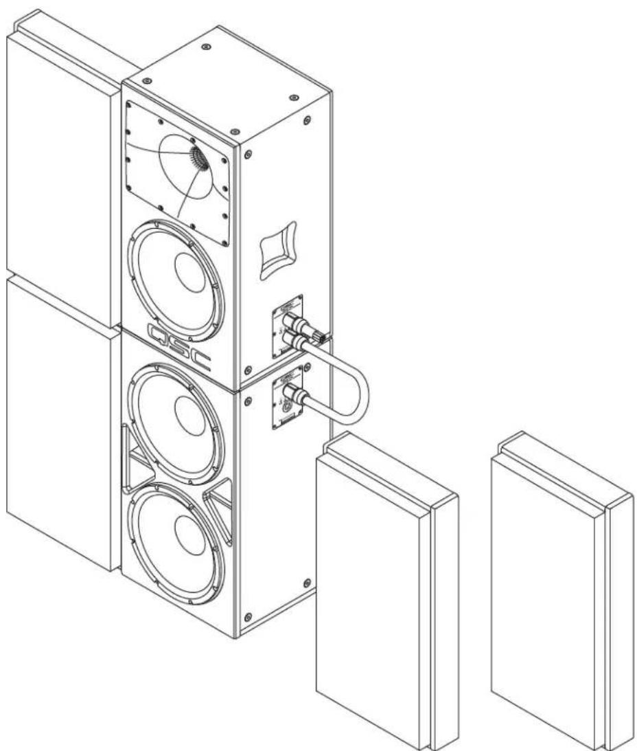
1. Stack the Loudspeakers

WARNING!: Make sure the loudspeakers are secured in accordance with the applicable regulations.
Refer to – Figure 2.
Carefully place the RSC-112 box on top of the RSB-212 box so that the four rubber feet on the bottom of the RSC-112 are set securely into the four cups on top of the RSB-212. The NL8 connection panels of both units should be vertically aligned, and all four sides should be aligned flush with each other.
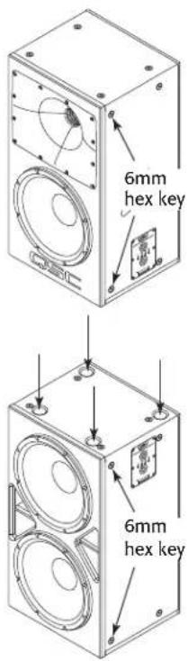
2. Install the Baffles
- Remove a total of eight M10 hex plugs; two toward the front of the left and right sides of each of the two boxes. Use a 6 mm hex wrench. — Figure 2
- Place a split washer then a flat washer on each of eight M10 hex bolts.
- Align the holes, in the two lower baffles, with the holes on the front edge of the subwoofer. — Figure 3
-
Insert four bolts with washers through the holes in the baffles and into the holes in the subwoofer.
-
Torque the four M10 bolts to no more than 10 ft/lbs (13.5 N.m). Use a 17 mm wrench.
-
Repeat this procedure for the top loudspeaker box.
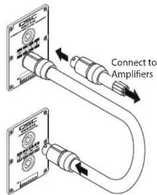
3. Connections
This section contains information about the connections between the DCA amplifiers and the RSC-112 and RSB-212 loudspeakers. For the remainder of the system connections, refer to the owner's manuals for the specific equipment. Refer to — Figure 4.

NOTE: Using standard, pre-made, NL8 connector/cables, ensures the wiring will be correct. This procedure assumes that all eight wires are connected in all NL8 connectors. — Figure 5 shows the male connector's pinout.
- Plug the NL8 connector/cable, from the amplifiers, into the top NL8 receptacle on the RSC-112 enclosure. If you are using a fully wired NL8 cable, you may use any connector on either box.
- Plug a short NL8 to NL8 jumper cable into one receptacle on each box.
Frequency Range DCA 1222 DCA 3022 NL8 Pin Loudspeaker
| Sub- - CH 1- 1- RSB-212 | ||||
| Sub+ | - | CH 1+ | 1+ | RSB-212 |
| LF- | - CH 2- 2- RSC-112 | |||
| LF+ | - | CH 2+ | 2+ | RSC-112 |
| MF- | CH 1- - | 3- RSC-112 | ||
| MF+ | CH 1+ | - | 3+ | RSC-112 |
| HF- | CH 2- - | 4- RSC-112 | ||
| HF+ | CH 2+ | - | 4+ | RSC-112 |
text_image
6mm hex key 6mm hex key- Figure 2 -

text_image
Technical diagram of a multi-level refrigerator with labeled parts and exploded view- Figure 3 -
text_image
Connect to Amplifiers- Figure 4 -

text_image
4- 4+ 3- 1+ 3± 1- 2+ 2- 1-- Figure 5 -
Suspending the Reference Monitor System Loudspeakers
The typical installation of the Reference Monitor System is to stack the loudspeakers as detailed above. However in the event that you need to suspend the loudspeakers, the RSC-112 and RSB-212 each have 16 M10 suspension points: four on top, four on the bottom and four on each side that can be used to suspend the loudspeakers.

WARNING!: Read and follow these instructions carefully. If the loudspeakers are not suspended properly, they could fall, causing personal injury and damage to the equipment.
Rules for Suspension
- Consult a professional mechanical or structural engineer, licensed in the jurisdiction of the sound system installation, to review, verify, and approve all attachments to the building or structure.
- Employ the services of a certified, professional rigger for hoisting, positioning, and attaching the equipment to the supporting structure.
- Correct use of all suspension hardware and components is imperative in sound system suspension and deployment.
• Always calculate suspended loads before lifting to make sure suspension components and hardware are used within their respective load limits. - Consult local codes and regulations to fully understand the requirements for suspended loads in the venue in which you will suspend the equipment.
- Use only the M10 installation points for suspending the array.
- Be absolutely certain of the integrity of any structural member intended to support suspended loads. Hidden structural members can have hidden structural weakness.
- Never assume anything! Owner or third-party supplied suspension attachment points may not be adequate for suspending the loads.
- Before lifting, always inspect all components (enclosures, suspension brackets, pins, frames, bolts, nuts, slings, shackles, etc.) for cracks, wear, deformation, corrosion, missing, loose, or damaged parts that could reduce the strength of the assembly. Discard any worn, defective, or suspect parts and replace them with new appropriately load-rated parts.
Using Integrated Suspension Points
The Suspension points are located such that a single loudspeaker can be hung in a variety of orientations. The suspension points are designed for use with two M10-1.5, 30 mm long shoulder eyebolts.
- Remove the appropriate plugs from the M10 installation points using a 6 mm hex key.
- Thread an eyebolt into each of the appropriate M10 installation points.
- Tighten the eyebolts until their shoulders are snug against the enclosure.
- Continue to rotate the eyebolts until they reach the optimum desired in-line position. Do not overtighten.
- The loudspeakers are ready for suspension.
Dimensions

- Figure 6 -
- Figure 7 -

text_image
15 in. 381 mm 4.6 in. 117 mm 15 in. 381 mm 28 in. 711 mmRBK12

text_image
4.6 in. 117 mm 28 in. 117 mm- Figure 8 -
Specifications
RSC-112 RSB-212
| Rated Coverage Angle (-6 dB) 90 degrees Axisymmetric Omnidirectional | ||
| Frequency Range1(-10dB) | 55 Hz to 20 kHz 30 Hz to 20 kHz (including RSC-112) | |
| Crossover Frequencies (up to 48 dB/oct using dedicated Q-Sys DSP) | - | |
| LF | 80 to 120 Hz (selectable) | |
| MF | 1.2 kHz | |
| HF | 7 kHz | |
| Rated Noise Power (Voltage)2 | ||
| LF | 500 W / 63 V | 1000 W |
| MF | 80 W / 25 V | - |
| HF | 55 W / 20 V | - |
| Sensitivity3 | ||
| LF | 94 dB | 96 dB |
| MF | 107 dB | - |
| HF | 105 dB | - |
| Maximum continuous SPL4 | ||
| LF | 121 dB | 120.5 dB |
| MF | 126 dB | - |
| HF | 122 dB | - |
| Maximum peak SPL4 | ||
| LF | 127 dB | 126.5 dB |
| MF | 132 dB | - |
| HF | 128 dB | - |
| Rated Impedance | ||
| LF | 8Ω | 3Ω |
| MF | 8Ω | - |
| HF | 8Ω | - |
| Recommended Amplifier Power | ||
| LF | 1000 W | 1000 W |
| MF | 500 W | - |
| HF | 300 W | - |
| Transducers | ||
| LF | 12 in. (305 mm) woofer | 2 x 12 in. (305 mm) Kevlar-reinforced paper cone woofers, 3 in. voice coils |
| MF/HF: coaxial neodymium compression driver with: | ||
| MF | 3.5" (90mm) MF voice coil | |
| HF | 1.75" (44mm) HF voice coil | |
| Input/Output Connector Parallel NL8: 1/thru, 2/LF, 3/MF, 4/HF Parallel NL8: 1/to sub, 2/thru, 3/thru, 4/thru | ||
| Enclosure Material 15-ply Baltic birch plywood 15-ply Baltic birch plywood | ||
| Dimensions (HxWxD) 28.5" x 15.1" x 13.5" (725 x 383 x 344 mm) 28.5" x 15.1" x 13.5" (725 x 383 x 344 mm) | ||
| Net Weight 66.4 lb (30.1 kg) 89 lb (40.4 kg) | ||
| Included Accessories None | None | |
| Optional Accessories RBK12 baffle wing kit | RBK12 baffle wings kit | |
1 Free-field, unprocessed
2 AES2-1984 noise signal for 2 hrs
3 On-Axis, free-field sensitivity, 2.83V, 1 m
4 Calculated from rated noise voltage and sensitivity
QSC®
QSC Self Help Portal
Read knowledge base articles and discussions, download software and firmware, view product documents and training videos, and create support cases.
https://qscprod.force.com/selfhelpportal/s/
Customer Support
Refer to the Contact Us page on the QSC website for Technical Support and Customer Care, including their phone numbers and hours of operation.
https://www.qsc.com/contact-us/