iCard 300U UAG5100 - Licence logicielle et extension ZYXEL - Free user manual and instructions
Find the device manual for free iCard 300U UAG5100 ZYXEL in PDF.

User questions about iCard 300U UAG5100 ZYXEL
0 question about this device. Answer the ones you know or ask your own.
Ask a new question about this device
Download the instructions for your Licence logicielle et extension in PDF format for free! Find your manual iCard 300U UAG5100 - ZYXEL and take your electronic device back in hand. On this page are published all the documents necessary for the use of your device. iCard 300U UAG5100 by ZYXEL.
USER MANUAL iCard 300U UAG5100 ZYXEL
Unified Access Gateway
Version 4.00
Edition 1, 02/2014
User's Guide
Default Login Details
| LAN IP Address | http://172.16.0.1 (LAN1)http://172.17.0.1 (LAN2) |
| User Name admin | |
| Password 1234 |
IMPORTANT!
READ CAREFULLY BEFORE USE.
KEEP THIS GUIDE FOR FUTURE REFERENCE.
Screenshots and graphics in this book may differ slightly from your product due to differences in your product firmware or your computer operating system. Every effort has been made to ensure that the information in this manual is accurate.
Related Documentation
- Quick Start Guide
The Quick Start Guide shows how to connect the UAG and access the Web Configurator wizards. (See the wizard real time help for information on configuring each screen.) It also contains a package contents list.
- CLI Reference Guide
The CLI Reference Guide explains how to use the Command-Line Interface (CLI) to configure the UAG.
Note: It is recommended you use the Web Configurator to configure the UAG.
• Web Configurator Online Help
Click the help icon in any screen for help in configuring that screen and supplementary information.
Contents Overview
Introduction 18
Hardware Installation and Connection 32
Printer Deployment 35
Installation Setup Wizard 43
Quick Setup Wizards ....51
Dashboard 66
Monitor 77
Registration 111
Wireless 114
Interfaces 118
Trunks 158
Policy and Static Routes 166
Zones 176
DDNS 180
NAT 185
Chapter 1 Introduction......18
1.1 Overview ...... 18
1.2 Default Zones, Interfaces, and Ports .... 18
1.3 Management Overview ...... 19
1.4 Web Configurator ....20
1.4.1 Web Configurator Access ......20
1.4.2 Web Configurator Screens Overview ......21
1.4.3 Navigation Panel 24
1.4.4 Tables and Lists ....28
1.5 Stopping the UAG ....31
Chapter 2 Hardware Installation and Connection ....32
2.1 Rack-mounting 32
2.2 Front Panel 33
2.2.1 Front Panel LEDs 34
2.3 Rear Panel 34
Chapter 3 Printer Deployment....35
3.1 Overview ...... 35
3.2 Attach the Printer to the UAG 35
3.3 Set up an Internet Connection on the UAG 35
3.4 Allow the UAG to Monitor and Manage the Printer 36
3.5 Turn on Web Authentication on the UAG 38
3.6 Generate a Free Guest Account 40
Chapter 4 Installation Setup Wizard....43
4.1 Installation Setup Wizard Screens 43
4.1.1 Internet Access Setup - WAN Interface 43
4.1.2 Internet Access: Ethernet 44
4.1.3 Internet Access: PPPoE 45
4.1.4 Internet Access: PPTP 47
4.1.5 Internet Access Setup - Second WAN Interface 48
4.1.6 Internet Access - Finish 49
4.2 Device Registration 50
Chapter 5
Quick Setup Wizards....51
5.1 Quick Setup Overview ....51
5.2 WAN Interface Quick Setup .... 51
5.2.1 Choose an Ethernet Interface .... 52
5.2.2 Select WAN Type 52
5.2.3 Configure WAN IP Settings ....53
5.2.4 ISP and WAN Connection Settings ....53
5.2.5 Quick Setup Interface Wizard: Summary 55
5.3 VPN Setup Wizard .... 56
5.3.1 Welcome ....57
5.3.2 VPN Setup Wizard: Wizard Type ....57
5.3.3 VPN Express Wizard - Scenario 58
5.3.4 VPN Express Wizard - Configuration 59
5.3.5 VPN Express Wizard - Summary 59
5.3.6 VPN Express Wizard - Finish 60
5.3.7 VPN Advanced Wizard - Scenario 61
5.3.8 VPN Advanced Wizard - Phase 1 Settings 62
5.3.9 VPN Advanced Wizard - Phase 2 63
5.3.10 VPN Advanced Wizard - Summary 64
5.3.11 VPN Advanced Wizard - Finish 65
Chapter 6
Dashboard 66
6.1 Overview 66
6.1.1 What You Can Do in this Chapter 66
6.2 The Dashboard Screen 66
6.2.1 The CPU Usage Screen 71
6.2.2 The Memory Usage Screen 72
6.2.3 The Active Sessions Screen 73
6.2.4 The VPN Status Screen 73
6.2.5 The DHCP Table Screen ....74
6.2.6 The Number of Login Users Screen 75
Chapter 7
Monitor....77
7.1 Overview 77
7.1.1 What You Can Do in this Chapter 77
7.2 The Port Statistics Screen ....78
7.2.1 The Port Statistics Graph Screen 79
7.3 The Interface Status Screen 80
7.4 The Traffic Statistics Screen 83
7.5 The Session Monitor Screen 85
7.6 The DDNS Status Screen 87
7.7 The IP/MAC Binding Monitor Screen 88
7.8 The Login Users Screen 89
7.9 The UPnP Port Status Screen 90
7.10 The USB Storage Screen 91
7.11 The Dynamic Guest Screen 92
7.12 The AP List Screen 94
7.12.1 Station Count of AP 95
7.13 The Radio List Screen 96
7.13.1 AP Mode Radio Information .....98
7.14 The Station List Screen 99
7.15 The Printer Status Screen 100
7.16 The VPN 1-1 Mapping Status Screen ....101
7.16.1 VPN 1-1 Mapping Statistics ....102
7.17 The IPSec Monitor Screen 103
7.17.1 Regular Expressions in Searching IPSec SAs 104
7.18 The Log Screen 104
7.18.1 View AP Log 107
7.18.2 Dynamic Users Log 109
Chapter 8 Registration......111
8.1 Overview ...... 111
8.1.1 What You Can Do in this Chapter 111
8.1.2 What you Need to Know 111
8.2 Registration Screen 112
8.3 Service Screen 112
Chapter 9 Wireless....114
9.1 Overview ...... 114
9.1.1 What You Can Do in this Chapter 114
9.2 Controller Screen 114
9.3 AP Management Screen 115
9.3.1 Edit AP List 116
Chapter 10 Interfaces......118
10.1 Interface Overview 118
10.1.1 What You Can Do in this Chapter 118
10.1.2 What You Need to Know 118
10.2 Port Grouping 120
10.2.1 Port Grouping Overview 121
10.2.2 Port Grouping Screen 121
10.3 Ethernet Summary Screen 122
10.3.1 Ethernet Edit 123
10.3.2 Object References ...... 129
10.3.3 DHCP Extended Options Add/Edit 130
10.4 PPP Interfaces 132
10.4.1 PPP Interface Summary 133
10.4.2 PPP Interface Add/Edit 134
10.5 VLAN Interfaces 138
10.5.1 VLAN Interface Summary Screen 139
10.5.2 VLAN Interface Add/Edit 140
10.6 Bridge Interfaces 145
10.6.1 Bridge Interface Summary 147
10.6.2 Bridge Interface Add/Edit 148
10.7 Virtual Interfaces 152
10.7.1 Virtual Interfaces Add/Edit 153
10.8 Interface Technical Reference 154
Chapter 11
Trunks 158
11.1 Overview 158
11.1.1 What You Can Do in this Chapter 158
11.1.2 What You Need to Know 158
11.2 The Trunk Summary Screen 161
11.2.1 Configuring a User-Defined Trunk 162
11.2.2 Configuring the System Default Trunk 164
Chapter 12
Policy and Static Routes....166
12.1 Policy and Static Routes Overview 166
12.1.1 What You Can Do in this Chapter 166
12.1.2 What You Need to Know 166
12.2 Policy Route Screen 168
12.2.1 Policy Route Add/Edit Screen 170
12.3 IP Static Route Screen 173
12.3.1 Static Route Add/Edit Screen 174
12.4 Policy Routing Technical Reference .... 175
Chapter 13
Zones 176
13.1 Zones Overview 176
13.1.1 What You Can Do in this Chapter ....176
13.1.2 What You Need to Know 176
13.2 The Zone Screen 177
13.2.1 Zone Add/Edit 178
Chapter 14
DDNS....180
14.1 DDNS Overview .... 180
14.1.1 What You Can Do in this Chapter ....180
14.1.2 What You Need to Know .... 180
14.2 The DDNS Screen 181
14.2.1 The Dynamic DNS Add/Edit Screen 182
Chapter 15
NAT....185
15.1 NAT Overview 185
15.1.1 What You Can Do in this Chapter ....185
15.1.2 What You Need to Know 185
15.2 The NAT Screen 186
15.2.1 The NAT Add/Edit Screen 187
15.3 NAT Technical Reference 190
Chapter 16
16.1.1 What You Can Do in this Chapter ....192
16.1.2 What You Need to Know .... 193
16.2 The VPN 1-1 Mapping General Screen ....193
16.2.1 The VPN 1-1 Mapping Add/Edit Screen ....194
16.3 The VPN 1-1 Mapping Profile Screen ....195
Chapter 17
HTTP Redirect....197
17.1 Overview ...... 197
17.1.1 What You Can Do in this Chapter ....197
17.1.2 What You Need to Know 197
17.2 The HTTP Redirect Screen 198
17.2.1 The HTTP Redirect Add/Edit Screen 199
Chapter 18
SMTP Redirect 201
18.1 Overview ......201
18.1.1 What You Can Do in this Chapter ....201
18.1.2 What You Need to Know ....201
18.2 The SMTP Redirect Screen 202
18.2.1 The SMTP Redirect Add/Edit Screen 203
Chapter 19
ALG 205
19.1 ALG Overview ......205
19.1.1 What You Can Do in this Chapter ....205
19.1.2 What You Need to Know ....205
19.1.3 Before You Begin 206
19.2 The ALG Screen 206
Chapter 20
UPnP 207
20.1 Overview 207
20.2 What You Need to Know ....207
20.2.1 NAT Traversal 207
20.2.2 Cautions with UPnP 208
20.3 UPnP Screen 208
20.4 Technical Reference 209
20.4.1 Using UPnP in Windows XP Example ......209
20.4.2 Web Configurator Easy Access 211
Chapter 21
IP/MAC Binding......214
21.1 IP/MAC Binding Overview ......214
21.1.1 What You Can Do in this Chapter ....214
21.1.2 What You Need to Know 214
21.2 IP/MAC Binding Summary 215
21.2.1 IP/MAC Binding Edit 216
21.2.2 Static DHCP Add/Edit 217
21.3 IP/MAC Binding Exempt List ....217
Chapter 22
Layer 2 Isolation ....219
22.1 Overview ...... 219
22.1.1 What You Can Do in this Chapter ....219
22.2 Layer-2 Isolation General Screen 220
22.3 White List 220
22.3.1 Add/Edit White List Rule ......221
Chapter 23
IPnP 223
23.1 Overview ......223
23.1.1 What You Can Do in this Chapter 223
23.2 IPnP Screen 224
Chapter 24
Web Authentication 225
24.1 Overview 225
24.1.1 What You Can Do in this Chapter ...... 225
24.1.2 What You Need to Know 226
24.2 Web Authentication Screen 226
24.2.1 Adding/Editing an Authentication Policy 232
24.2.2 User-aware Access Control Example 233
24.3 Walled Garden Screen 240
24.3.1 Adding/Editing a Walled Garden URL 241
24.3.2 Walled Garden Login Example 242
24.4 Advertisement Screen 242
24.4.1 Adding/Editing an Advertisement URL 243
Chapter 25
Firewall 245
25.1 Overview 245
25.1.1 What You Can Do in this Chapter 245
25.1.2 What You Need to Know 245
25.2 The Firewall Screen 247
25.2.1 Configuring the Firewall Screen 248
25.2.2 The Firewall Add/Edit Screen 251
25.3 The Session Control Screen 252
25.3.1 The Session Control Add/Edit Screen 253
25.4 Firewall Rule Configuration Example 254
25.5 Firewall Rule Example Applications .....256
Chapter 26
Billing....259
26.1 Overview 259
26.1.1 What You Can Do in this Chapter ....259
26.1.2 What You Need to Know 259
26.2 The General Screen ....260
26.3 The Billing Profile Screen 261
26.3.1 The Account Generator Screen 263
26.3.2 The Account Redeem Screen 266
26.3.3 The Billing Profile Add/Edit Screen 268
26.4 The Discount Screen 269
26.4.1 The Discount Add/Edit Screen 270
26.5 The Payment Service General Screen 270
26.5.1 The Payment Service Custom Service Screen 272
Chapter 27
Printer Manager 275
27.1 Overview ...... 275
27.1.1 What You Can Do in this Chapter 275
27.2 The General Screen 275
27.3 The Printout Configuration Screen 277
27.3.1 Reports Overview ......278
27.3.2 Key Combinations ......278
27.3.3 Daily Account Summary 279
27.3.4 Monthly Account Summary ......279
27.3.5 Account Report Notes 280
27.3.6 System Status 280
Chapter 28
Free Time....282
28.1 Overview 282
28.1.1 What You Can Do in this Chapter 282
28.2 The Free Time Screen 282
Chapter 29
SMS 286
29.1 Overview 286
29.1.1 What You Can Do in this Chapter 286
29.2 The SMS Screen 286
Chapter 30
IPSec VPN....288
30.1 Virtual Private Networks (VPN) Overview 288
30.1.1 What You Can Do in this Chapter 288
30.1.2 What You Need to Know 289
30.1.3 Before You Begin 289
30.2 The VPN Connection Screen 290
30.2.1 The VPN Connection Add/Edit Screen 291
30.3 The VPN Gateway Screen 297
30.3.1 The VPN Gateway Add/Edit Screen 297
30.4 IPSec VPN Background Information ....303
Chapter 31
Bandwidth Management....315
31.1 Overview 315
31.1.1 What You Can Do in this Chapter ....315
31.1.2 What You Need to Know .... 315
31.2 The Bandwidth Management Screen .... 319
31.2.1 The Bandwidth Management Add/Edit Screen 321
Chapter 32
User/Group 325
32.1 Overview 325
32.1.1 What You Can Do in this Chapter ....325
32.1.2 What You Need To Know .... 325
32.2 User Summary Screen 327
32.2.1 User Add/Edit Screen 328
32.3 User Group Summary Screen 331
32.3.1 Group Add/Edit Screen 331
32.4 The User/Group Setting Screen 332
32.4.1 Default User Settings Edit Screen 335
32.4.2 User Aware Login Example ....336
32.5 User /Group Technical Reference 337
Chapter 33
AP Profile....339
33.1 Overview 339
33.1.1 What You Can Do in this Chapter ....339
33.1.2 What You Need To Know ....339
33.2 Radio Screen 340
33.2.1 Add/Edit Radio Profile 342
33.3 SSID Screen 345
33.3.1 SSID List .... 345
33.3.2 Add/Edit SSID Profile 347
33.3.3 Security List 348
33.3.4 Add/Edit Security Profile 350
33.3.5 MAC Filter List .... 352
33.3.6 Add/Edit MAC Filter Profile 353
Chapter 34
Addresses 354
34.1 Overview ...... 354
34.1.1 What You Can Do in this Chapter ....354
34.1.2 What You Need To Know ....354
34.2 Address Summary Screen 354
34.2.1 Address Add/Edit Screen 355
34.3 Address Group Summary Screen 356
34.3.1 Address Group Add/Edit Screen 357
Chapter 35
Services 359
35.1 Overview 359
35.1.1 What You Can Do in this Chapter 359
35.1.2 What You Need to Know .... 359
35.2 The Service Summary Screen 360
35.2.1 The Service Add/Edit Screen .... 361
35.3 The Service Group Summary Screen 362
35.3.1 The Service Group Add/Edit Screen 362
Chapter 36
Schedules 364
36.1 Overview 364
36.1.1 What You Can Do in this Chapter 364
36.1.2 What You Need to Know .... 364
36.2 The Schedule Summary Screen 365
36.2.1 The One-Time Schedule Add/Edit Screen 366
36.2.2 The Recurring Schedule Add/Edit Screen 367
Chapter 37
AAA Server 368
37.1 Overview 368
37.1.1 RADIUS Server 368
37.1.2 What You Can Do in this Chapter 368
37.1.3 What You Need To Know ....368
37.2 RADIUS Server Summary 369
37.2.1 Adding/Editing a RADIUS Server 369
Chapter 38
Authentication Method....372
38.1 Overview 372
38.1.1 What You Can Do in this Chapter ....372
38.1.2 Before You Begin 372
38.2 Authentication Method Objects ....372
38.2.1 Creating an Authentication Method Object 373
Chapter 39
Certificates 375
39.1 Overview 375
39.1.1 What You Can Do in this Chapter ....375
39.1.2 What You Need to Know ....375
39.1.3 Verifying a Certificate 377
39.2 The My Certificates Screen 378
39.2.1 The My Certificates Add Screen ....379
39.2.2 The My Certificates Edit Screen .... 381
39.2.3 The My Certificates Import Screen 384
39.3 The Trusted Certificates Screen 385
39.3.1 The Trusted Certificates Edit Screen 386
39.3.2 The Trusted Certificates Import Screen 389
Chapter 40
ISP Accounts....391
40.1 Overview ......391
40.1.1 What You Can Do in this Chapter ....391
40.2 ISP Account Summary 391
40.2.1 ISP Account Add/Edit 392
Chapter 41
System 394
41.1 Overview 394
41.1.1 What You Can Do in this Chapter ....394
41.2 Host Name 395
41.3 USB Storage 395
41.4 Date and Time 396
41.4.1 Pre-defined NTP Time Servers List ....399
41.4.2 Time Server Synchronization 399
41.5 Console Port Speed 400
41.6 DNS Overview 401
41.6.1 DNS Server Address Assignment 401
41.6.2 Configuring the DNS Screen 401
41.6.3 Address Record 403
41.6.4 PTR Record 403
41.6.5 Adding/Editing an Address/PTR Record 403
41.6.6 Domain Zone Forwarder 404
41.6.7 Adding/Editing a Domain Zone Forwarder 404
41.6.8 MX Record 405
41.6.9 Adding/Editing a MX Record ....406
41.6.10 Adding/Editing a DNS Service Control Rule 406
41.7 WWW Overview 407
41.7.1 Service Access Limitations .... 407
41.7.2 System Timeout ....407
41.7.3 HTTPS 408
41.7.4 Configuring WWW Service Control 408
41.7.5 Service Control Rules 411
41.7.6 Customizing the WWW Login Page 412
41.7.7 HTTPS Example 416
41.8 SSH 423
41.8.1 How SSH Works 424
41.8.2 SSH Implementation on the UAG 425
41.8.3 Requirements for Using SSH 425
41.8.4 Configuring SSH 425
41.8.5 Secure Telnet Using SSH Examples 426
41.9 Telnet 428
41.9.1 Configuring Telnet 428
41.10 FTP 429
41.10.1 Configuring FTP 429
41.11 SNMP 430
41.11.1 Supported MIBs 431
41.11.2 SNMP Traps 432
41.11.3 Configuring SNMP 432
41.12 Language 434
Chapter 42
Log and Report 435
42.1 Overview 435
42.1.1 What You Can Do In this Chapter 435
42.2 Email Daily Report 435
42.3 Log Settings Screens 437
42.3.1 Log Settings Summary 438
42.3.2 Edit System Log Settings 439
42.3.3 Edit Log on USB Storage Setting 442
42.3.4 Edit Remote Server Log Settings 444
42.3.5 Log Category Settings Screen 446
Chapter 43
File Manager....450
43.1 Overview 450
43.1.1 What You Can Do in this Chapter 450
43.1.2 What you Need to Know 450
43.2 The Configuration File Screen 452
43.3 The Firmware Package Screen 456
43.4 The Shell Script Screen 458
Chapter 44
Diagnostics 461
44.1 Overview 461
44.1.1 What You Can Do in this Chapter 461
44.2 The Diagnostics Screen 461
44.2.1 The Diagnostics Files Screen 462
44.3 The Packet Capture Screen 463
44.3.1 The Packet Capture Files Screen 465
44.4 Core Dump Screen 466
44.4.1 Core Dump Files Screen 467
44.5 The System Log Screen 467
Chapter 45
Packet Flow Explore....469
45.1 Overview 469
45.1.1 What You Can Do in this Chapter 469
45.2 The Routing Status Screen 469
45.3 The SNAT Status Screen 474
Chapter 46
Reboot 478
46.1 Overview 478
46.1.1 What You Need To Know ....478
46.2 The Reboot Screen 478
Chapter 47
Shutdown......479
47.1 Overview 479
47.1.1 What You Need To Know 479
47.2 The Shutdown Screen 479
Chapter 48
Troubleshooting....480
48.1 Resetting the UAG 487
48.2 Getting More Troubleshooting Help 488
Appendix A Legal Information....489
Index 492
1.1 Overview
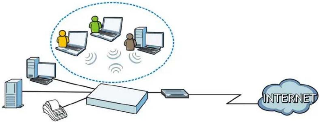
The UAG is a comprehensive service gateway. If you have a "statement printer", such as SP350E, you can connect it directly to the UAG, allowing you to easily print subscriber statements. The UAG is ideal for offices, coffee shops, libraries, hotels and airport terminals catering to subscribers that seek Internet access. You should have an Internet account already set up and have been given usernames, passwords etc. required for Internet access.
flowchart
graph TD
    A["Server"] --> B["Printer"]
    B --> C["Router"]
    C --> D["Phone"]
    D --> E["Internet"]
    style A fill:#f9f,stroke:#333
    style B fill:#ccf,stroke:#333
    style C fill:#cfc,stroke:#333
    style D fill:#fcc,stroke:#333
    style E fill:#cff,stroke:#333
You can use web authentication to allow guests to access the network only after they authenticate with the UAG through a specifically designated login web page. You can also forward the authenticated client's e-mail messages to a specific SMTP server.
The UAG also provides bandwidth management, NAT, port forwarding, policy routing, DHCP server and many other powerful features. The UAG's security features include firewall, VPN and certificates.
The UAG lets you set up multiple networks for your company. The De-Militarized Zone (DMZ) increases LAN security by providing separate ports for connecting publicly accessible servers. The UAG also provides two separate LAN networks. You can set ports to be part of the LAN1, LAN2 or DMZ. Alternatively, you can deploy the UAG as a transparent firewall in an existing network with minimal configuration.
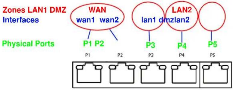
1.2 Default Zones, Interfaces, and Ports
The default configurations for zones, interfaces, and ports are as follows. References to interfaces may be generic rather than the specific name used in your model. For example, this guide may use "the WAN interface" rather than "P1" or "P2".
Figure 1 Zones, Interfaces, and Physical Ethernet Ports
text_image
Zones LAN1 DMZ Interfaces WAN wan1 wan2 Physical Ports P1 P2 P3 P4 P5 LAN1 dmzlan2 lan1 dmzlan21.3 Management Overview
You can manage the UAG in the following ways.
Web Configurator
The Web Configurator allows easy UAG setup and management using an Internet browser. This User's Guide provides information about the Web Configurator.
Figure 2 Managing the UAG: Web Configurator

text_image
ZyXEL UAG5100 Welcome admin | Help About Site Map Object Reference Console DASHBOARD Widget Settings Virtual Device ZyXEL UAG5100 UNITED ACCESS DATAWAY PWR S1S CONSOLE P4 P1 P2 P3 P4 Device Information System Name: uag5100 Model Name: UAG5100 Serial Number: S122819000011 MAC Address Range: CC:5D:4E:63:D4:64 ~ CC:5D:4E:63:D4:68 Firmware Version: V4.00(AAPN.0)E/2 / 11.22 / 2013-12-05 17:32:48 Licensed Service StatusStatus Name Version Expiration
1 Default Extension User r/a 2 Default Managed AP Service r/a AP Information AI AP: Online Management AP: 1 Offline Management AP: 0 Un-Management AP: 0 AI Station: Station: 2 Top 5 StationAP MAC Mac Station Count AP Description
1 B0:B2 D:C:6F:0E:47 3 AP-B0D2DC6F0E47 Top 5 IPv4 Firewall Rules that Blocked TrafficFrom To Description Hits
System Resources CPU Usage 0 %Command-Line Interface (CLI)
The CLI allows you to use text-based commands to configure the UAG. Access it using remote management (for example, SSH or Telnet) or via the physical or Web Configurator console port. See the Command Reference Guide for CLI details. The default settings for the console port are:
Table 1 Console Port Default Settings
| SETTING VALUE | |
| Speed 115200 bps | |
| Data Bits 8 | |
| Parity None | |
| Stop Bit 1 | |
| Flow Control Off |
1.4 Web Configurator
In order to use the Web Configurator, you must:
- Use one of the following web browser versions: Internet Explorer 7.0 and later versions, Mozilla Firefox 9.0 and later versions, Safari 4.0 and later versions, or Google Chrome 10.0 and later versions.
- Allow pop-up windows (blocked by default in Windows XP Service Pack 2)
- Enable JavaScripts, Java permissions, and cookies
The recommended screen resolution is 1024 x 768 pixels and higher.
1.4.1 Web Configurator Access
1 Make sure your UAG hardware is properly connected. See the Quick Start Guide.
2 In your browser go to http://172.16.0.1 or http://172.17.0.1. The Login screen appears.
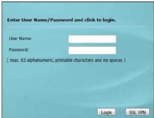
text_image
Enter User Name/Password and click to login. User Name: Password: ( max. 63 alphanumeric, printable characters and no spaces ) Login SSL VPN3 Type the user name (default: "admin") and password (default: "1234").
4 Click Login. If you logged in using the default user name and password, the Update Admin Info screen appears. Otherwise, the dashboard appears.
5 Follow the directions in the Update Admin Info screen. If you change the default password, the Login screen appears after you click Apply. If you click Ignore, the Installation Setup Wizard opens if the UAG is using its default configuration; otherwise the dashboard appears.
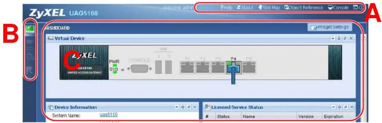
text_image
ZyXEL UAG5100 Welcome admin Help About Site Map Object Reference Console A B CASHBOARD Widget Settings Virtual Device ZYXEL UAG5100 UNIFIED ACCESS GATEWAY PWR SYB CONSOLE USB 1 2 P1 P2 P3 P4 P5 Device Information System Name: uag5100 Licensed Service StatusStatus Name Version Expiration
1.4.2 Web Configurator Screens Overview
The Web Configurator screen is divided into these parts (as illustrated on page 21):
• A - title bar
• B - navigation panel
• C - main window
1.4.2.1 Title Bar
Figure 3 Title Bar

The title bar icons in the upper right corner provide the following functions.
Table 2 Title Bar: Web Configurator Icons
| LABEL DESCRIPTION | |
| Logout Click this to log out of the Web Configurator. | |
| Help Click this to open the help page for the current screen. | |
| About Click this to display basic information about the UAG. | |
| Site Map Click this to see an overview of links to the Web Configurator screens. | |
| Object Reference | Click this to check which configuration items reference an object. |
| Console | Click this to open a Java-based console window from which you can run command line interface (CLI) commands. You will be prompted to enter your user name and password. See the Command Reference Guide for information about the commands. |
| CLI Click this to open a popup window that displays the CLI commands sent by the Web Configurator to the UAG. | |
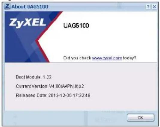
About
Click About to display basic information about the UAG.
Figure 4 About
text_image
Z About UAG5100 ZyXEL UAG5100 Did you check www.zyexl.com today? Boot Module: 1.22 Current Version: V4.00(AAPN.0)b2 Released Date: 2013-12-05 17:32:48 CKThe following table describes labels that can appear in this screen.
Table 3 About
| LABEL DESCRIPTION | |
| Boot Module | This shows the version number of the software that handles the booting process of the UAG. |
| Current Version This shows the firmware version of the UAG. | |
| Released Date | This shows the date (yyyy-mm-dd) and time (hh:mm:ss) when the firmware is released. |
| OK Click this to close the screen. | |
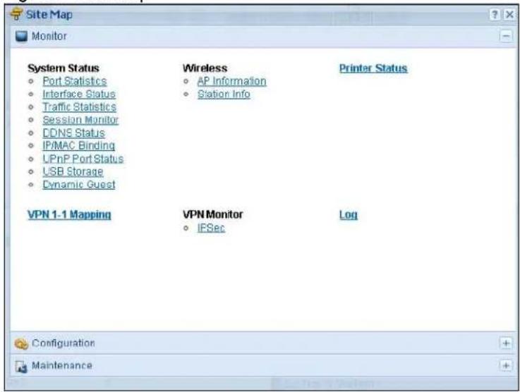
Site Map
Click Site MAP to see an overview of links to the Web Configurator screens. Click a screen's link to go to that screen.
Figure 5 Site Map
text_image
Site Map Monitor System Status • Port Statistics • Interface Status • Traffic Statistics • Session Monitor • DDNS Status • IP/MAC Binding • LPnP Port Status • LSB Storage • Dynamic Guest Wireless • AP Information • Station Info Printer Status VPN 1-1 Mapping VPN Monitor • IPSec Log Configuration MaintenanceObject Reference
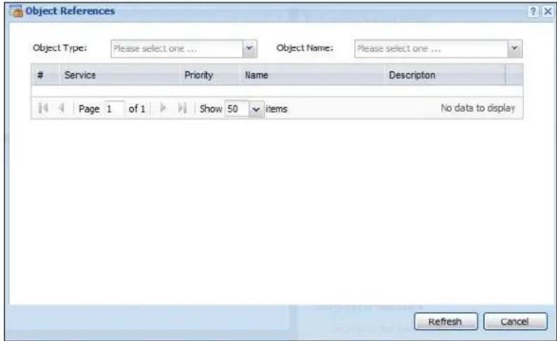
Click Object Reference to open the Object Reference screen. Select the type of object and the individual object and click Refresh to show which configuration settings reference the object.
Figure 6 Object Reference
text_image
Object References Object Type: Please select one ... Object Name: Please select one ...Service Priority Name Description
Page 1 of 1 Show 50 items No data to display Refresh CancelThe fields vary with the type of object. The following table describes labels that can appear in this screen.
Table 4 Object References
| LABEL DESCRIPTION | |
| Object Name | This identifies the object for which the configuration settings that use it are displayed. Click the object's name to display the object's configuration screen in the main window. |
| # | This field is a sequential value, and it is not associated with any entry. |
| Service | This is the type of setting that references the selected object. Click a service's name to display the service's configuration screen in the main window. |
| Priority | If it is applicable, this field lists the referencing configuration item's position in its list, otherwise N/ A displays. |
| Name | This field identifies the configuration item that references the object. |
| Description If thereferencing configuration item has a description configured, it displays here. | |
| Refresh Click this to update the information in this screen. | |
| Cancel Click Cancel to close the screen. | |
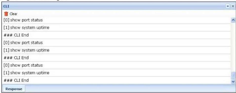
CLI Messages
Click CLI to look at the CLI commands sent by the Web Configurator. Open the pop-up window and then click some menus in the web configurator to display the corresponding commands.
Figure 7 CLI Messages
text_image
CLI Clear [0] show port status [1] show system uptimeCLI End
[0] show port status [1] show system uptimeCLI End
[0] show port status [1] show system uptimeCLI End
ResponseClick Clear to remove the currently displayed information.
See the Command Reference Guide for information about the commands.
1.4.3 Navigation Panel
Use the navigation panel menu items to open status and configuration screens. Click the arrow in the middle of the right edge of the navigation panel to hide the panel or drag to resize it. The following sections introduce the UAG's navigation panel menus and their screens.
Figure 8 Navigation Panel

text_image
ZyXEL UAG5100 Welcome admin | 1:24:27 ?Help ?About ?St PORT Statistics General Settings Poll Interval: 5 (1-60 seconds) Set Interval Statistics Table Switch To Graphic ViewPort Status TxPkts RxPkts Collisions T:
1 1 Down 0 0 0 0 2 2 Down 0 0 0 0 3 3 Down 0 0 0 0 4 4 100M/Full 49143 47233 0 0 5 5 Down 0 0 0 0 Page 1 of 1 Show 50 Items System Up Time: 05:29:45Dashboard
The dashboard displays general device information, system status, system resource usage, licensed service status, and interface status in widgets that you can re-arrange to suit your needs. See Chapter 6 on page 66 for details on the dashboard.
Monitor Menu
The monitor menu screens display status and statistics information.
Table 5 Monitor Menu Screens Summary
| FOLDER OR LINK TAB FUNCTION | ||
| System Status | ||
| Port Statistics | Display packet statistics for each physical port. | |
| Interface Status | Display general interface information and packet statistics. | |
| Traffic Statistics | Collect and display traffic statistics. | |
| Session Monitor | Display the status of all current sessions. | |
| DDNS Status Display the status of the UAG's DDNS domain names. | ||
| IP/MAC Binding | List the devices that have received an IP address from UAG interfaces using IP/MAC binding. | |
| Login Users List the users currently logged into the UAG. | ||
| UPnP Port Status | List the NAT port mapping rules that UPnP creates on the UAG. | |
| USB Storage Display details about a USB device connected to the UAG. | ||
| Dynamic Guest List the dynamic guest accounts in the UAG's local database. | ||
| Wireless | ||
| AP Information | AP List | Display information about the connected APs. |
| Radio List | Display information about the radios of the connected APs. | |
| Station Info Display information about the connected stations. | ||
| Printer Status | ||
| Printer Status | Display information about the connected statement printers. | |
| VPN 1-1 Mapping | ||
| VPN 1-1 Mapping | Display the status of the active users to which the UAG applied a VPN 1-1 mapping rule. | |
| Statistics | Display statistics for each of the VPN 1-1 mapping rules. | |
| VPN Monitor | ||
| IPSec | Display and manage the active IPSec SAs. | |
| Log | List log entries. | |
| View Log | List log entries for the UAG. | |
| View AP Log | Allow you to query connected APs and view log entries for them. | |
| Dynamic Users Log | Display the UAG's dynamic guest account log messages. | |
Configuration Menu
Use the configuration menu screens to configure the UAG's features.
Table 6 Configuration Menu Screens Summary
| FOLDER OR LINK | TAB | FUNCTION | ||
| Quick Setup | Quickly configure WAN interfaces or VPN connections. | |||
| Licensing | ||||
| Registration Registration Register the device and activate trial services. | ||||
| Service View the licensed service status and upgrade licensed services. | ||||
| Wireless | ||||
| Controller | Configuration | Configure how the UAG handles APs that newly connect to the network. | ||
| AP Management | Mgmt. AP List | Edit wireless AP information, remove APs, and reboot them. | ||
| Network | ||||
| Interface | Port Grouping | Use this screen to configure port groups and set the UAG's flexible ports as WAN1, WAN2, LAN1, LAN2 or DMZ. | ||
| Ethernet | Manage Ethernet interfaces and virtual Ethernet interfaces. | |||
| PPP Create and manage PPPoE and PPTP interfaces. | ||||
| VLAN | Create and manage VLAN interfaces and virtual VLAN interfaces. | |||
| Bridge Create and manage bridges and virtual bridge interfaces. | ||||
| Trunk Create and manage trunks (groups of interfaces) for load balancing. | ||||
| Routing | Policy Route | Create and manage routing policies. | ||
| Static Route Create and manage IP static routing information. | ||||
| Zone | Configure zones used to define various policies. | |||
| DDNS | Define and manage the UAG's DDNS domain names. | |||
| NAT | Set up and manage port forwarding rules. | |||
| VPN 1-1 Mapping | General | Enable and configure VPN 1-1 mapping to assign a public IP address to each of users that match the rules. | ||
| Profile | Configure a pool profile which defines the public IP address that the UAG assigns to the matched users and the interface through which the user's traffic is forwarded. | |||
| HTTP Redirect | Set up and manage HTTP redirection rules. | |||
| SMTP Redirect | Set up and manage SMTP redirection rules. | |||
| ALG | Configure SIP, H.323, and FTP pass-through settings. | |||
| UPnP | enable UPnP and NAT-PMP on your UAG. | |||
| IP/MAC Binding | Summary | Configure IP to MAC address bindings for devices connected to each supported interface. | ||
| Exempt List | Configure ranges of IP addresses to which the UAG does not apply IP/MAC binding. | |||
| Layer 2 Isolation | General | Enable layer-2 isolation on the UAG and the internal interface(s). | ||
| White List | Enable and configure the white list. | |||
| IPnP | Enable IPnP on the UAG and the internal interface(s). | |||
| Web Authentication | Web Authentication | Define rules to force user authentication for network access. | ||
| Walled Garden | Create walled garden links that display in the login screen. | |||
| Advertisement | Enable and set advertisement links. | |||
| Firewall | Firewall | Create and manage level-3 traffic rules. | ||
| Session Control | Limit the number of concurrent client NAT/firewall sessions. | |||
| Billing | General | Configure the general billing settings, such as the accounting method. | ||
| Billing Profile | Configure the billing profiles for the web-based account generator and each button on the connected statement printer. | |||
| Discount Configure d | discount price plans. | |||
| Payment Service Enable online payment service and configure the service pages. | ||||
| Printer Manager | General | Configure the printer list and enable printer management. | ||
| Printout Configuration | Customize the account printout. | |||
| Free Time | Free Time | Allow users to get a free account for Internet surfing during the specified time period. | ||
| SMS | SMS | Enable the SMS service to send dynamic guest account information in text messages. | ||
| VPN | ||||
| IPSec VPN VPN | Connection Configure | PSec tunnels. | ||
| VPN Gateway Configure | IKE tunnels. | |||
| BWM | BWM | Enable and configure bandwidth management rules. | ||
| Object | ||||
| User/Group | User | Create and manage users. | ||
| Group | Create and manage groups of users. | |||
| Setting | Manage default settings for all users, general settings for user sessions, and rules to force user authentication. | |||
| AP Profile | Radio | Create and manage wireless radio settings files that can be associated with different APs. | ||
| SSID | Create and manage wireless SSID, security, and MAC filtering settings files that can be associated with different APs. | |||
| Address | Address | Create and manage host, range, and network (subnet) addresses. | ||
| Address Group Create and manage groups of addresses. | ||||
| Service | Service | Create and manage TCP and UDP services. | ||
| Service Group | Create and manage groups of services. | |||
| Schedule | Schedule | Create one-time and recurring schedules. | ||
| AAA Server | RADIUS | Configure the RADIUS settings. | ||
| Auth. Method | Authentication Method | Create and manage ways of authenticating users. | ||
| Certificate | My Certificates | Create and manage the UAG's certificates. | ||
| Trusted Certificates | Import and manage certificates from trusted sources. | |||
| ISP Account | ISP Account | Create and manage ISP account information for PPPoE/PPTP interfaces. | ||
| System | ||||
| Host Name | Configure the system and domain name for the UAG. | |||
| USB Storage | Settings | Configure the settings for the connected USB devices. | ||
| Date/Time | Configure the current date, time, and time zone in the UAG. | |||
| Console Speed | Set the console speed. | |||
| DNS | Configure the DNS server and address records for the UAG. | |||
| WWW | Service Control | Configure HTTP, HTTPS, and general authentication. | ||
| Login Page | Configure how the login and access user screens look. | |||
| SSH Configure S | SH server and SSH service settings. | |||
| TELNET Configure | e telnet server settings for the UAG. | |||
| FTP Configure FTP | server settings. | |||
| SNMP Configure | SNMP communities and services. | |||
| Language Select | the Web Configurator language. | |||
| Log & Report | ||||
| Email Daily Report | Configure where and how to send daily reports and what reports to send. | |||
| Log Settings Configure the system log, e-mail logs, and remote syslog servers. | ||||
Maintenance Menu
Use the maintenance menu screens to manage configuration and firmware files, run diagnostics, and reboot or shut down the UAG.
Table 7 Maintenance Menu Screens Summary
| FOLDER OR LINK | TAB FUNCTION | |
| File Manager | Configuration File | Manage and upload configuration files for the UAG. |
| Firmware Package | View the current firmware version and to upload firmware. | |
| Shell Script | Manage and run shell script files for the UAG. | |
| Diagnostics | Diagnostic | Collect diagnostic information. |
| Packet Capture | Capture packets for analysis. | |
| Core Dump | Connect a USB device to the UAG and save the UAG operating system kernel to it here. | |
| System Log | Connect a USB device to the UAG and archive the UAG system logs to it here. | |
| Packet Flow Explore | Routing Status Check how the UAG determines where to route a packet. | |
| SNAT Status | View a clear picture on how the UAG converts a packet's source IP address and check the related settings. | |
| Reboot | Restart the UAG. | |
| Shutdown | Turn off the UAG. | |
1.4.4 Tables and Lists
Web Configurator tables and lists are flexible with several options for how to display their entries.
Click a column heading to sort the table's entries according to that column's criteria.
Figure 9 Sorting Table Entries by a Column's Criteria
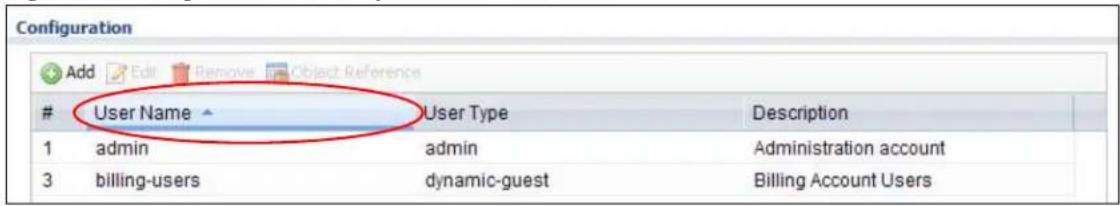
text_image
ConfigurationUser Name User Type Description
1 admin admin Administration account 3 billing-users dynamic-guest Billing Account UsersClick the down arrow next to a column heading for more options about how to display the entries. The options available vary depending on the type of fields in the column. Here are some examples of what you can do:
- Sort in ascending or descending (reverse) alphabetical order
- Select which columns to display
- Group entries by field
• Show entries in groups - Filter by mathematical operators (<, >, or =) or searching for text
Figure 10 Common Table Column Options
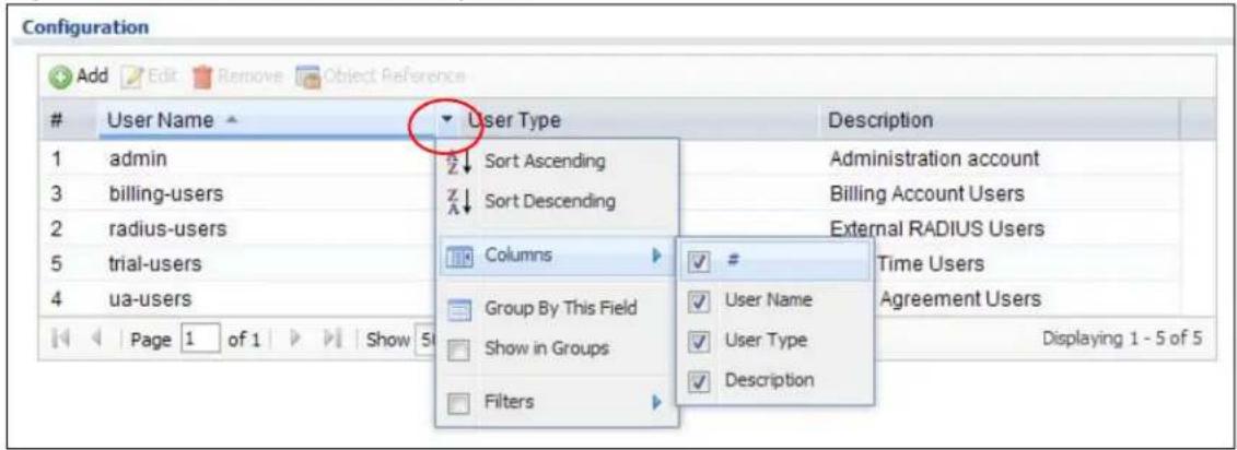
text_image
Configuration Add Edit Remove Object ReferenceUser Name ▼ User Type Description
1 admin Sort Ascending Administration account 3 billing-users Sort Descending Billing Account Users 2 radius-users Columns External RADIUS Users 5 trial-users Time Users 4 ua-users Group By This Field User Name Agreement Users Show in Groups User Type Displaying 1 - 5 of 5 Filters DescriptionSelect a column heading cell's right border and drag to re-size the column.
Figure 11 Resizing a Table Column

text_image
Configuration Add Edit Remove Object ReferenceUser Name User Type Description
4 ua-users dynamic-guest User Agreement Users 5 trial-users dynamic-guest Free Time Users 2 radius-users ext-user External RADIUS UsersSelect a column heading and drag and drop it to change the column order. A green check mark displays next to the column's title when you drag the column to a valid new location.
Figure 12 Moving Columns
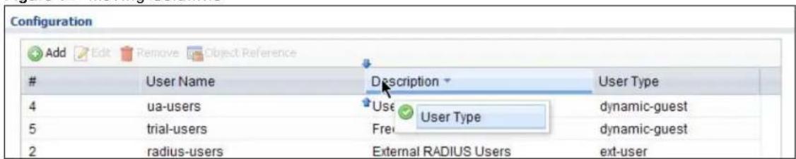
text_image
Configuration Add Edit Remove Object ReferenceUser Name Description User Type
4 ua-users Use User Type dynamic-guest 5 trial-users Fre dynamic-guest 2 radius-users External RADIUS Users ext-userUse the icons and fields at the bottom of the table to navigate to different pages of entries and control how many entries display at a time.
Figure 13 Navigating Pages of Table Entries

text_image
Page 1 of 1 Show 50 items Displaying 1 - 5 of 5The tables have icons for working with table entries. You can often use the [Shift] or [Ctrl] key to select multiple entries to remove, activate, or deactivate.
Figure 14 Common Table Icons

text_image
User Configuration Add Edit Remove Activate Inactivate Connect Disconnect Object ReferenceStatus Name Base Interface Account Profile
1 testPPPoE wan1 WAN1_PPPoE_ACCOUNT Page 1 of 1 Show 50 items Displaying 1 - 1 of 1Here are descriptions for the most common table icons.
Table 8 Common Table Icons
| LABEL DESCRIPTION | |
| Add Click this | is to create a new entry. For features where the entry's position in the numbered list is important (features where the UAG applies the table's entries in order like the firewall for example), you can select an entry and click Add to create a new entry after the selected entry. |
| Edit | Double-click an entry or select it and click Edit to open a screen where you can modify the entry's settings. In some tables you can just click a table entry and edit it directly in the table. For those types of tables small red triangles display for table entries with changes that you have not yet applied. |
| Remove | To remove an entry, select it and click Remove. The UAG confirms you want to remove it before doing so. |
| Activate | To turn on an entry, select it and click Activate. |
| Inactivate | To turn off an entry, select it and click Inactivate. |
| Connect | To connect an entry, select it and click Connect. |
| Disconnect | To disconnect an entry, select it and click Disconnect. |
| Object Reference | Select an entry and click Object Reference to check which settings use the entry. |
| Move | To change an entry's position in a numbered list, select it and click Move to display a field to type a number for where you want to put that entry and press [ENTER] to move the entry to the number that you typed. For example, if you type 6, the entry you are moving becomes number 6 and the previous entry 6 (if there is one) gets pushed up (or down) one. |
Working with Lists
When a list of available entries displays next to a list of selected entries, you can often just double-click an entry to move it from one list to the other. In some lists you can also use the [Shift] or [Ctrl] key to select multiple entries, and then use the arrow button to move them to the other list.
Figure 15 Working with Lists
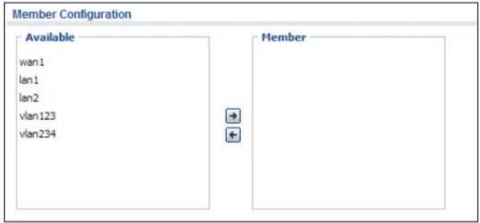
text_image
Member Configuration Available wan1 lan1 lan2 vlan123 vlan234 Member1.5 Stopping the UAG
Always use Maintenance > Shutdown > Shutdown or the shutdown command before you turn off the UAG or remove the power. Not doing so can cause the firmware to become corrupt.
Hardware Installation and Connection
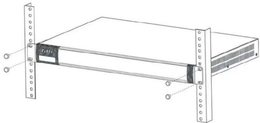
2.1 Rack-mounting
Use the following steps to mount the UAG on an EIA standard size, 19-inch rack or in a wiring closet with other equipment using a rack-mounting kit. Make sure the rack will safely support the combined weight of all the equipment it contains and that the position of the UAG does not make the rack unstable or top-heavy. Take all necessary precautions to anchor the rack securely before installing the unit.
Note: Leave 10 cm of clearance at the sides and 20 cm in the rear.
Use a #2 Phillips screwdriver to install the screws.
Note: Failure to use the proper screws may damage the unit.
1 Align one bracket with the holes on one side of the UAG and secure it with the included bracket screws (smaller than the rack-mounting screws).
2 Attach the other bracket in a similar fashion.

text_image
Zyxel3 After attaching both mounting brackets, position the UAG in the rack and up the bracket holes with the rack holes. Secure the UAG to the rack with the rack-mounting screws.
natural_image
Technical line drawing of a server rack unit with mounting flanges and a central drive (no text or symbols)2.2 Front Panel
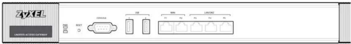
This section introduces the UAG's front panel.
Figure 16 UAG Front Panel
text_image
3yXEL UNIFIED ACCESS GATEWAY PWR RESET CONGOLE USB WIN LAN/DAZ V1 V2 V3 V4 V5Ethernet Ports
The 1000Base-T auto-negotiating, auto-crossover Ethernet ports support 10/100/1000 Mbps Gigabit Ethernet so the speed can be 100 Mbps or 1000 Mbps. The duplex mode is full at 1000 Mbps and half or full at 10/100 Mbps. An auto-negotiating port can detect and adjust to the optimum Ethernet speed (10/100/1000 Mbps) and duplex mode (full duplex or half duplex) of the connected device. An auto-crossover (auto-MDI/MDI-X) port automatically works with a straight-through or crossover Ethernet cable. The factory default negotiation settings for the Ethernet ports on the UAG are speed: auto, duplex: auto, and flow control: on (you cannot configure the flow control setting, but the UAG can negotiate with the peer and turn it off if needed).
The color-coded Ethernet port supports the IEEE 802.3at High Power over Ethernet (PoE) standard and can receive power of up to 30W per Ethernet port from a PoE switch via an 8-pin CAT 5 Ethernet cable. This helps eliminate the need for power sockets.
USB 2.0 Ports
Connect a USB storage device to a USB port on the UAG to archive the UAG system logs or save the UAG operating system kernel to it.
Console Port
Connect this port to your computer (using an RS-232 cable) if you want to configure the UAG using the command line interface (CLI) via the console port.
For local management, you can use a computer with terminal emulation software configured to the following parameters:
• VT100 terminal emulation
• 115200 bps
- No parity, 8 data bits, 1 stop bit
- No flow control
Connect the male 9-pin end of the RS-232 console cable to the console port of the UAG. Connect the female end to a serial port (COM1, COM2 or other COM port) of your computer.
2.2.1 Front Panel LEDs
The following tables describe the LEDs.
Table 9 Front Panel LEDs
| LED COLOR STATUS DESCRIPTION | |||
| PWR Off The UAG is turned off. | |||
| Red On There is a hardware component failure. Shut down the device, wait for a few minutes and then restart the device (see Section 1.5 on page 31). If the LED turns red again, then please contact your vendor. | |||
| SYS Green Off The UAG is not ready or has failed. | |||
| Red On The UAG had an error or has failed. | |||
| P1~P5 Green On This port has a successful link to a 10/100 Mbps Ethernet network | |||
2.3 Rear Panel
The following figure shows the rear panel of the UAG. The rear panel contains a connector for the power receptacle.
Figure 17 Rear Panel

text_image
AC INPUT 100V~240V 50/66Hz 0.6A MAXPrinter Deployment
3.1 Overview
This chapter shows you how to set up an external statement printer (SP350E for example) and deploy it in your network with the UAG.
In the following examples, you will:
- Attach the printer to the UAG.
- Set up an Internet connection on the UAG.
- Allow the UAG to monitor and manage the printer.
- Turn on web authentication on the UAG.
- Generate a free guest account.
3.2 Attach the Printer to the UAG
This section uses the SP350E as an example. Refer to the printer documentation for detailed information about paper loading.
1 Connect the Ethernet port of the printer to one LAN port of the UAG.
2 Connect the power socket of the printer to a power outlet. Turn on the printer.
The printer is acting as a DHCP client by default and will obtain an IP address from the connected UAG. Make sure the UAG is turned on already and the DHCP server is enabled on its LAN interface(s).
3.3 Set up an Internet Connection on the UAG
1 Connect the WAN port of the UAG to a broadband modem or router.
2 Connect your computer to one of the available LAN port on the UAG.
3 Log into the UAG web configurator. See Section 1.4 on page 20 on how to access the web configurator.
4 Enter your Internet access information to set up a Internet connection. See Chapter 4 on page 43 for detailed information on how to use the setup wizard.
3.4 Allow the UAG to Monitor and Manage the Printer
Before you add the printer to the UAG's printer list, check the sticker on the printer's rear panel to see its MAC address.

text_image
ZyXEL Communications Corporation Made in Taiwan Model Number: SP350E Power Rating: 12V=3A Power Consumption: 34 Watt max. The device complies with Part 15 of the FCC Rules. Operation is subject to the following conditions: (1) this device may not cause harmful interference, and (2) this device must accept any interference received. including interference that may cause undesired operation. S331320000039 EC43F6D833581 Go to the Dashboard of the UAG web configurator.

text_image
ZyXEL UAG5100 Welcome admin L 7.048 ?Help Z About Site Map Object Reference Console CLI DASHBOARD Virtual Device ZyXEL UAG5100 UNIFIED ACCESS GATWAY PWR CONSOLE 1 2 P1 P2 P3 P4 P5 SYS Device Information System Name: uag5100 Model Name: UAO5100 Serial Number: S122S19000011 MAC Address Range: CC:5D.4E.63.D4:54 ~ CC:5D.4E.63.D4:58 Firmware Version: V4.00(AAPN.0)b3 / 1.22 / 2014-01-11 02 12:13 Licensed Service StatusStatus Name Version Expiration
1 Default Extension User N/A 2 Default Managed AP Service N/A AP Information All AP: Online Management AP: 1 Offline Management AP: 0 Un-Management AP: 0 All Station: Station: 1 DHCP Table: 2 System Uptime: 00:28:58 Current Date/Time: 2014-01-17 / 02:46:53 GMT+00:00 VPN Status: 0 Current Login User: admin (unlimited / 00:29:58) Number of Login Users: 1 Boot Status: OK Drop-in Mode Status: Off Top 5 Station StationAP MAC Max. Station Count AP Description
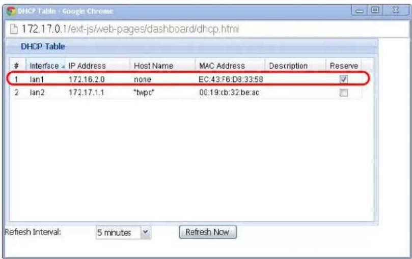
1 B0:B2:DC:6F:0... 1 AP-B0B2DC6F...2 Open the DHCP Table to find the IP address that is assigned to the printer's MAC address. Make sure the IP address is reserved for the printer. Write down the printer's IP address.
text_image
DHCP Table - Google Chrome 172.17.0.1/ext-js/web-pages/dashboard/dhcp.html DHCP TableInterface IP Address Host Name MAC Address Description Reserve
1 Ian1 172.16.2.0 none EC:43:F8:D8:33:58 ✓ 2 Ian2 172.17.1.1 "twpc" 00:19:xb:32:be:ac ✓ Refresh Interval: 5 minutes Refresh Now3 Go to the Configuration > Printer Manager screen. Click Add in the Printer List to create a new entry for your printer.

text_image
General Printout Configuration General Setting Enable Printer Manager Printer Settings Port: 9100 Encryption Reset key Printout Number of Copies: Printer List Add Rule Enable Printer Manager IPv4 Address: 172.16.2.0 Description: SP350E (Optional) OK Cancel Add Edit Remove Activate InactivateStatus IPv4 Address Description
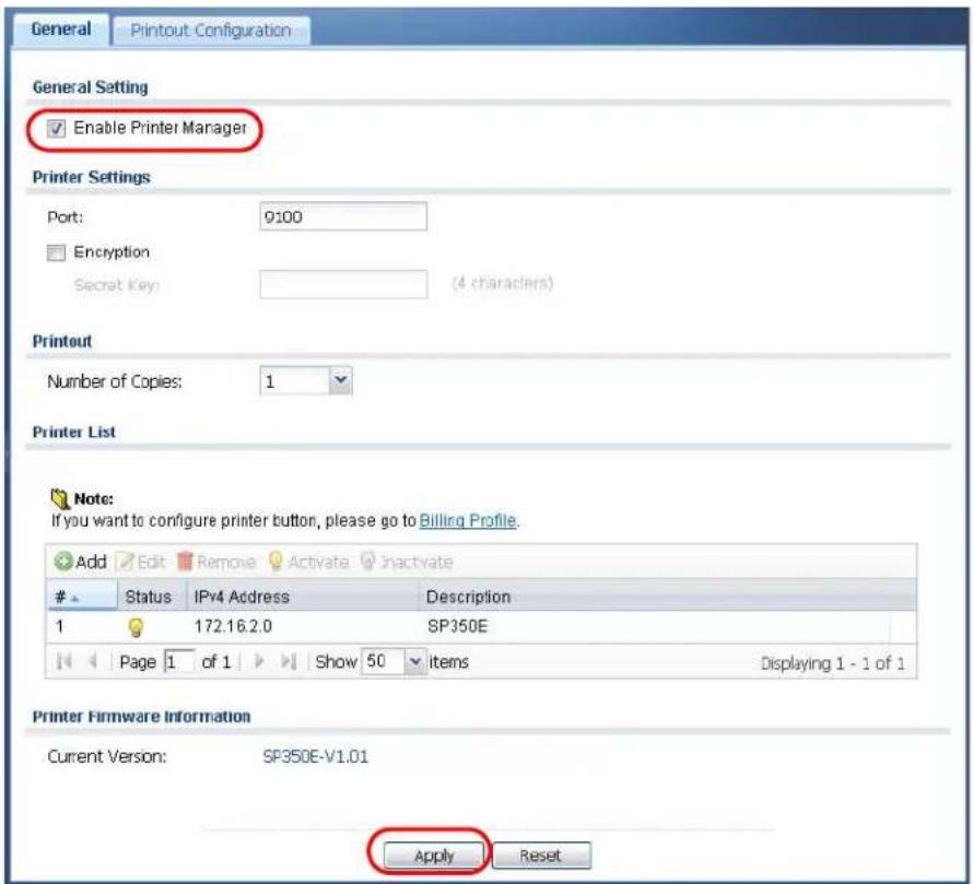
Page 1 of 1 Show 50 items No data to display Printer Firmware Information Current Version: SP350E-V1.01 Apply Reset4 After the printer's IP address is added to the printer list, select the Enable Printer Manager checkbox and then click Apply.
text_image
General Printout-Configuration General Setting Enable Printer Manager Printer Settings Port: 9100 Encryption Secret Key: (4 characters) Printout Number of Copies: 1 Printer List Note: If you want to configure printer button, please go to Billing Profile. Add Edit Remove Activate InactivateStatus IPv4 Address Description
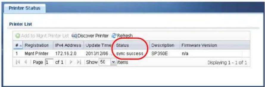
1 172.16.2.0 SP350E Page 1 of 1 Show 50 Items Displaying 1 - 1 of 1 Printer Firmware Information Current Version: SP350E-V1.01 Apply Reset5 Go to the Monitor > Printer Status screen to check if the UAG can connect to the printer (the printer status is sync success). In this screen, you can also click Discover Printer to detect and display the printer that is connected to the UAG, and then click Add to Mgmt Printer List to add the selected AP to the managed printer list automatically.
text_image
Printer List Add to Mont Printer List Discover Printer RefreshRegistration IPv4 Address Update Time Status Description Firmware Version
1 Mont Printer 172.16.2.0 2013/12/06 sync success SP350E n/a Page 1 cf 1 Show 50 items Displaying 1 - 1 of 1Note: You may need to wait up to 90 seconds for the UAG to synchronize with the printer successfully after you click Apply in the Configuration > Printer Manager screen.
3.5 Turn on Web Authentication on the UAG
With web authentication, users need to log in through a designated web page before they can access the network(s).
1 Go to the Configuration > Web Authentication screen.
2 Set Authentication to Web Portal.
3 Select Internal Web Portal to use the default login page.
4 Click Add to create a new web authentication policy.

text_image
Web Authentication Walled Garden Advertisement Web Authentication Type Type: None Web Portal User Agreement General Settings Logout IP: 1.1.1.1 Enable Terms of Service Internal Web Portal Welcome URL: (Optional) Preview: Terms of Service_ File Name: terms_of_service.html Download File Path: Select a File Path upload Restore File to Default: Restore Download the internal web portal terms of service example. External Web Portal Login URL: Logout URL: (Optional) Welcome URL: (Optional) Session URL: (Optional) Error URL: (Optional) Download the external web portal example. Exceptional Services Add RemoveExceptional Services
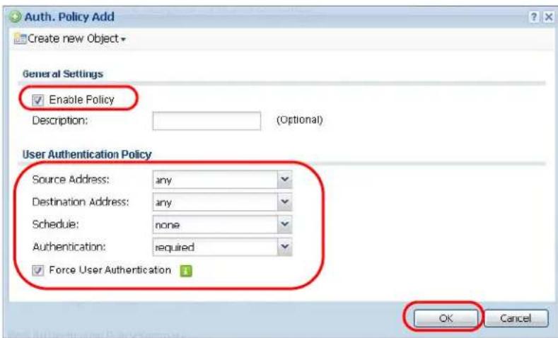
1 DNS Page 1 of 1 Show 50 items Displaying 1 - 1 of 1 Web Authentication Policy Summary Add Edit Remove Activate Inactivate Move St... P... Incoming... Source Destination Schedule Authentication Description 1 =lan2 any any none force D... any any any none unnecessary n/a Page 1 of 1 Show 50 items Displaying 1 - 2 of 2 Apply Reset5 The Auth. Policy Add screen displays. Set Authentication to required and select Force User Authentication to redirect all HTTP traffic to the default login page.
6 Click OK to save your changes.
text_image
Auth. Policy Add Create new Object General Settings Enable Policy Description: (Optional) User Authentication Policy Source Address: any Destination Address: any Schedule: none Authentication: required Force User Authentication OK Cancel7 Click Apply the Configuration > Web Authentication screen.
3.6 Generate a Free Guest Account
You can use the buttons on the printer or web-based account generator to create guest accounts based on the pre-defined billing settings (see Section 26.3 on page 261).
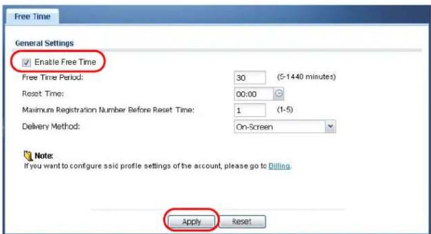
1 Go to the Configuration > Free Time screen.
2 Select the Enable Free Time checkbox to turn on this feature. Click Apply.
text_image
Free Time General Settings Enable Free Time Free Time Period: 30 (5-1440 minutes) Reset Time: 00:00 Maximum Registration Number Before Reset Time: 1 (1-5) Delivery Method: On-Screen Note: If you want to configure ssid profile settings of the account, please go to Billing. Apply Reset3 Whenever a user tries to access a web page, he/she will be redirect to the default login page.
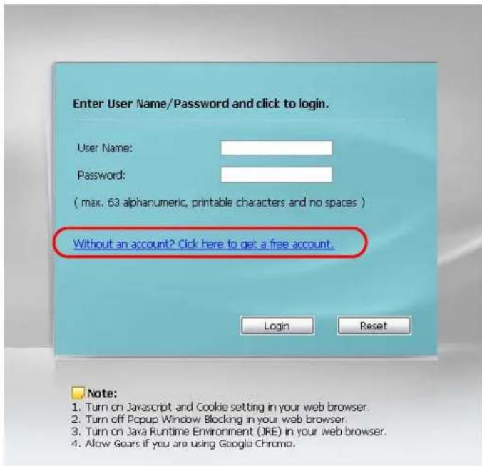
4 Click the link on the login page to get a free guest account.
text_image
Enter User Name/Password and click to login. User Name: Password: ( max. 63 alphanumeric, printable characters and no spaces ) Without an account? Click here to get a free account. Login Reset Note: 1. Turn on Javascript and Cookie setting in your web browser. 2. Turn off Popup Window Blocking in your web browser. 3. Turn on Java Runtime Environment (JRE) in your web browser. 4. Allow Gears if you are using Google Chrome.5 A Welcome screen displays. Select the free time service. Click OK to generate and show the account information on the web page.

text_image
Welcome Please choose the service plan from the following profile table. # Service Name Service Time Charge Unit 1 Free Time 30 minutes Free 1 OK6 Now you can use this account to access the Internet through the UAG for
Welcome
You may now use the internet.
IMPORTANT MAKE a note for your case-sensitive username and password for logging later. This will be your only opportunity to do so.
This is your account information, please keep this for your internet service.
Your username is ipuijp
Your password is 5x96kr
Your time period is 30 minutes
Login Now
Installation Setup Wizard
4.1 Installation Setup Wizard Screens
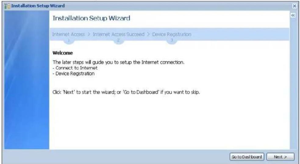
When you log into the Web Configurator for the first time or when you reset the UAG to its default configuration, the Installation Setup Wizard screen displays. This wizard helps you configure Internet connection settings and activate subscription services. This chapter provides information on configuring the Web Configurator's installation setup wizard. See the feature-specific chapters in this User's Guide for background information.
Figure 18 Installation Setup Wizard
text_image
Installation Setup Wizard Installation Setup Wizard Internet Access > Internet Access Succeed > Device Registration Welcome The later steps will guide you to setup the Internet connection. - Connect to Internet - Device Registration Click 'Next' to start the wizard; or 'Go to Dashboard' if you want to skip.- Click the double arrow in the upper right corner to display or hide the help.
- Click Go to Dashboard to skip the installation setup wizard or click Next to start configuring for Internet access.
4.1.1 Internet Access Setup - WAN Interface
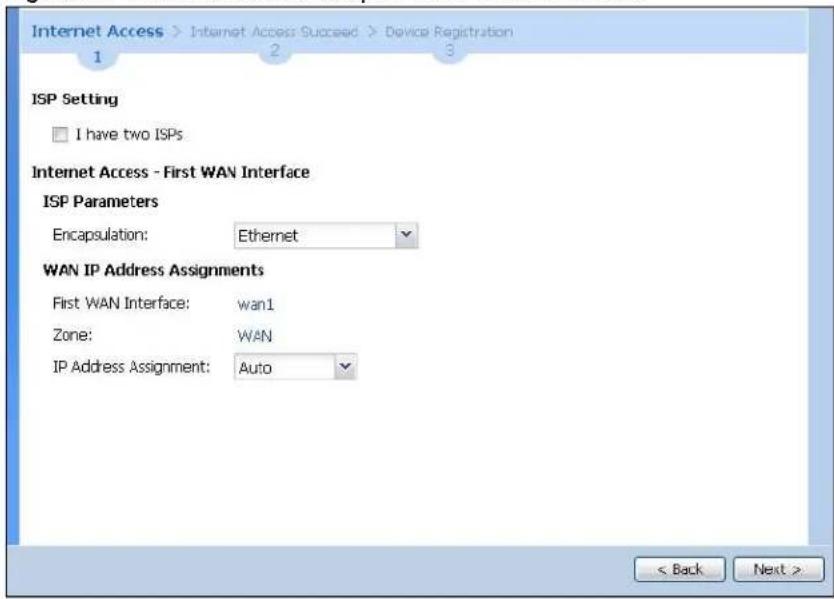
Use this screen to set how many WAN interfaces to configure and the first WAN interface's type of encapsulation and method of IP address assignment.
The screens vary depending on the encapsulation type. Refer to information provided by your ISP to know what to enter in each field. Leave a field blank if you don't have that information.
Note: Enter the Internet access information exactly as your ISP gave it to you.
Figure 19 Internet Access: Step 1: First WAN Interface
text_image
Internet Access > Internet Access Succeed > Device Registration 1 2 3 ISP Setting I have two ISPs Internet Access - First WAN Interface ISP Parameters Encapsulation: Ethernet WAN IP Address Assignments First WAN Interface: wan1 Zone: WAN IP Address Assignment: Auto < Back Next >- I have two ISPs: Select this option to configure two Internet connections. Leave it cleared to configure just one. This option appears when you are configuring the first WAN interface.
- Encapsulation: Choose the Ethernet option when the WAN port is used as a regular Ethernet. Otherwise, choose PPP Over Ethernet (PPPoE) or PPTP for a dial-up connection according to the information from your ISP.
- First WAN Interface: This is the interface you are configuring for Internet access.
• Zone: This is the security zone to which this interface and Internet connection belong. - IP Address Assignment: Select Auto if your ISP did not assign you a fixed IP address. Select Static if the ISP assigned a fixed IP address.
4.1.2 Internet Access: Ethernet
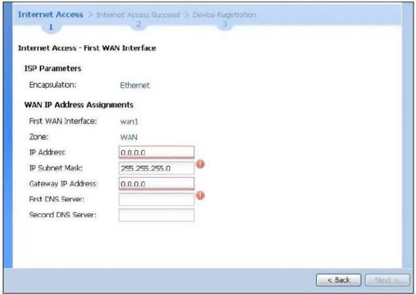
This screen is read-only if you set the previous screen's IP Address Assignment field to Auto. Use this screen to configure your IP address settings.
Note: Enter the Internet access information exactly as given to you by your ISP.
Figure 20 Internet Access: Ethernet Encapsulation
text_image
Internet Access > Internet Access Succeed > Device Registration 1 2 3 Internet Access - First WAN Interface ISP Parameters Encapsulation: Ethernet WAN IP Address Assignments First WAN Interface: wan1 Zone: WAN IP Address: 0.0.0.0 IP Subnet Mask: 255.255.255.0 Gateway IP Address: 0.0.0.0 First DNS Server: Second DNS Server: < Back Next >- Encapsulation: This displays the type of Internet connection you are configuring.
- First WAN Interface: This is the number of the interface that will connect with your ISP.
• Zone: This is the security zone to which this interface and Internet connection will belong. - IP Address: Enter your (static) public IP address. Auto displays if you selected Auto as the IP Address Assignment in the previous screen.
The following fields display if you selected static IP address assignment.
- IP Subnet Mask: Enter the subnet mask for this WAN connection's IP address.
- Gateway IP Address: Enter the IP address of the router through which this WAN connection will send traffic (the default gateway).
- First / Second DNS Server: These fields display if you selected static IP address assignment. The Domain Name System (DNS) maps a domain name to an IP address and vice versa. Enter a DNS server's IP address(es). The DNS server is extremely important because without it, you must know the IP address of a computer before you can access it. The UAG uses these (in the order you specify here) to resolve domain names for DDNS and the time server. Leave the field as 0.0.0.0 if you do not want to configure DNS servers.
4.1.3 Internet Access: PPPoE
Note: Enter the Internet access information exactly as given to you by your ISP.
Figure 21 Internet Access: PPPoE Encapsulation

text_image
Internet Access > Internet Access Succeed > Device Registration 1 2 3 Internet Access - First WAN Interface ISP Parameters Encapsulation: PPPoE Service Name: (Optional) Authentication Type: Chap/PAP User Name : Password: Retype to Confirm: □ Nailed-Up Idle timeout: 100 Seconds WAN IP Address Assignments First WAN Interface: wan1_ppp Zone: WAN IP Address: 0.0.0.0 First DNS Server: Second DNS Server: < Back Next >4.1.3.1 ISP Parameters
- Type the PPPoE Service Name from your service provider. PPPoE uses a service name to identify and reach the PPPoE server. You can use alphanumeric and -_@\$./ characters, and it can be up to 64 characters long.
-
Authentication Type - Select an authentication protocol for outgoing connection requests. Options are:
-
CHAP/ PAP - Your UAG accepts either CHAP or PAP when requested by the remote node.
• CHAP - Your UAG accepts CHAP only.
• PAP - Your UAG accepts PAP only.
• MSCHAP - Your UAG accepts MSCHAP only.
• MSCHAP-V2 - Your UAG accepts MSCHAP-V2 only. -
Type the User Name given to you by your ISP. You can use alphanumeric and -_@\$./ characters, and it can be up to 31 characters long.
- Type the Password associated with the user name. Use up to 64 ASCII characters except the [] and ?. This field can be blank.
- Select Nailed-Up if you do not want the connection to time out. Otherwise, type the Idle Timeout in seconds that elapses before the router automatically disconnects from the PPPoE server.
4.1.3.2 WAN IP Address Assignments
- First WAN Interface: This is the name of the interface that will connect with your ISP.
• Zone: This is the security zone to which this interface and Internet connection will belong. - IP Address: Enter your (static) public IP address. Auto displays if you selected Auto as the IP Address Assignment in the previous screen.
- First / Second DNS Server: These fields display if you selected static IP address assignment. The Domain Name System (DNS) maps a domain name to an IP address and vice versa. Enter a DNS server's IP address(es). The DNS server is extremely important because without it, you must know the IP address of a computer before you can access it. The UAG uses these (in the order you specify here) to resolve domain names for DDNS and the time server. Leave the field as 0.0.0.0 if you do not want to configure DNS servers. If you do not configure a DNS server, you must know the IP address of a machine in order to access it.
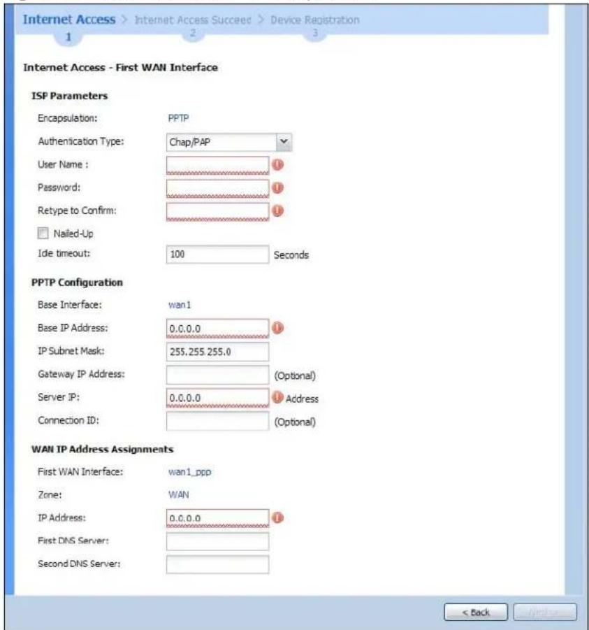
4.1.4 Internet Access: PPTP
Note: Enter the Internet access information exactly as given to you by your ISP.
Figure 22 Internet Access: PPTP Encapsulation
text_image
Internet Access > Internet Access Succeed > Device Registration 1 2 3 Internet Access - First WAN Interface ISP Parameters Encapsulation: PPTP Authentication Type: Chap/PAP User Name : Password: Retype to Confirm: □ Nailed-Up Ide timeout: 100 Seconds PPTP Configuration Base Interface: wan1 Base IP Address: 0.0.0.0 IP Subnet Mask: 255,255,255.0 Gateway IP Address: (Optional) Server IP: 0.0.0.0 Address Connection ID: (Optional) WAN IP Address Assignments First WAN Interface: wan1_ppp Zone: WAN IP Address: 0.0.0.0 First DNS Server: Second DNS Server: < Back Next>4.1.4.1 ISP Parameters
- Authentication Type - Select an authentication protocol for outgoing calls. Options are:
-
CHAP/ PAP - Your UAG accepts either CHAP or PAP when requested by the remote node.
• CHAP - Your UAG accepts CHAP only.
• PAP - Your UAG accepts PAP only.
• MSCHAP - Your UAG accepts MSCHAP only.
• MSCHAP-V2 - Your UAG accepts MSCHAP-V2 only. -
Type the User Name given to you by your ISP. You can use alphanumeric and -_@\$./ characters and it can be up to 31 characters long.
- Type the Password associated with the user name. Use up to 64 ASCII characters except the [] and ?. This field can be blank. Re-type your password in the next field to confirm it.
- Select Nailed-Up if you do not want the connection to time out. Otherwise, type the Idle Timeout in seconds that elapses before the router automatically disconnects from the PPTP server.
4.1.4.2 PPTP Configuration
- Base Interface: This identifies the Ethernet interface you configure to connect with a modem or router.
- Type a Base IP Address (static) assigned to you by your ISP.
- Type the IP Subnet Mask assigned to you by your ISP (if given).
- Gateway IP Address: Enter the IP address of the gateway if any.
- Server IP: Type the IP address of the PPTP server.
- Type a Connection ID or connection name. It must follow the "c:id" and "n:name" format. For example, C:12 or N:My ISP. This field is optional and depends on the requirements of your broadband modem or router. You can use alphanumeric and -_: characters, and it can be up to 31 characters long.
4.1.4.3 WAN IP Address Assignments
- First WAN Interface: This is the connection type on the interface you are configuring to connect with your ISP.
• Zone This is the security zone to which this interface and Internet connection will belong. - IP Address: Enter your (static) public IP address. Auto displays if you selected Auto as the IP Address Assignment in the previous screen.
- First / Second DNS Server: These fields display if you selected static IP address assignment. The Domain Name System (DNS) maps a domain name to an IP address and vice versa. Enter a DNS server's IP address(es). The DNS server is extremely important because without it, you must know the IP address of a computer before you can access it. The UAG uses these (in the order you specify here) to resolve domain names for DDNS and the time server. Leave the field as 0.0.0.0 if you do not want to configure DNS servers.
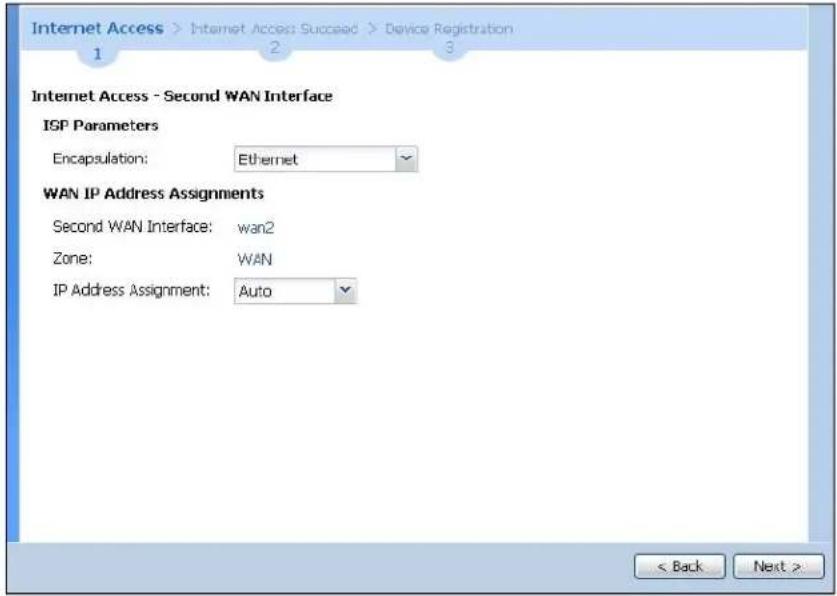
4.1.5 Internet Access Setup - Second WAN Interface
If you selected I have two ISPs, after you configure the First WAN Interface, you can configure the Second WAN Interface. The screens for configuring the second WAN interface are similar to the first (see Section 4.1.1 on page 43).
Figure 23 Internet Access: Step 1: Second WAN Interface
text_image
Internet Access > Internet Access Succeed > Device Registration 1 2 3 Internet Access - Second WAN Interface ISP Parameters Encapsulation: Ethernet WAN IP Address Assignments Second WAN Interface: wan2 Zone: WAN IP Address Assignment: Auto < Back Next >4.1.6 Internet Access - Finish
You have set up your UAG to access the Internet. A screen displays with your settings. If they are not correct, click Back.
Figure 24 Internet Access: Finish

text_image
Installation Setup Wizard Installation Setup Wizard Internet Access > Internet Access Succeed > Device Registration Congratulations. The Internet Access wizard is completed Summary of Internet Access configuration: First Setting Encapsulation: Ethernet First WAN Interface: WAN1 Zone: WAN IP Address Assignment: Auto < Back Next >Click Next and use the following screen to perform a basic registration (see Section 4.2 on page 50).
Alternatively, close the window to exit the wizard.
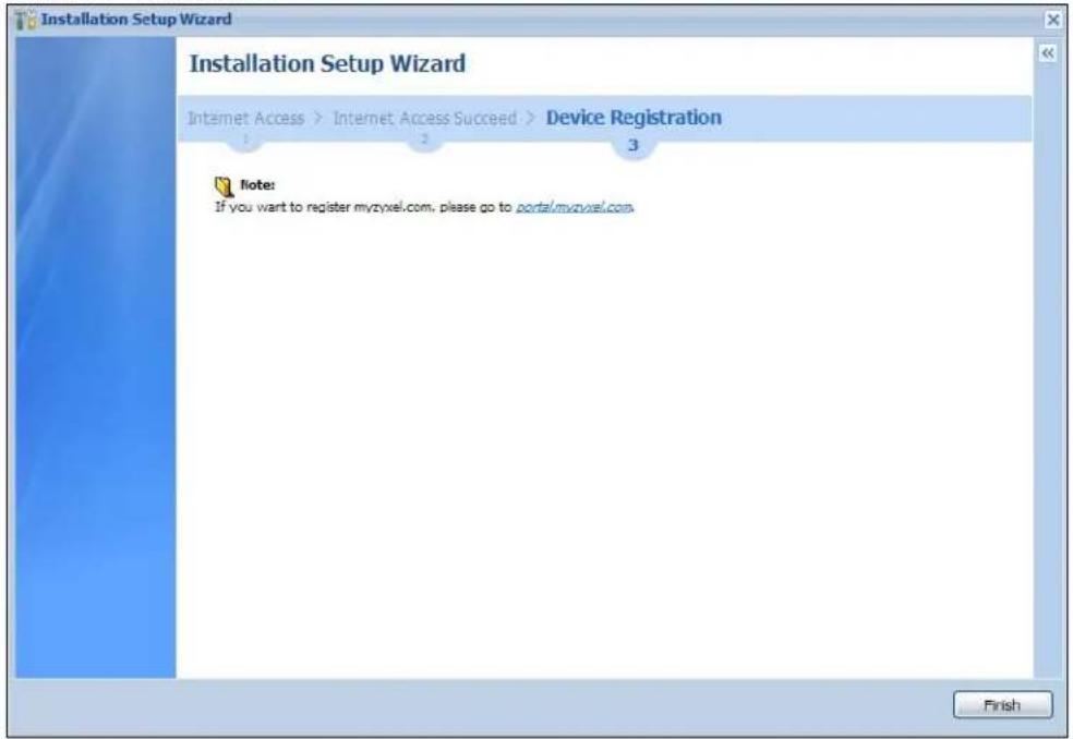
4.2 Device Registration
Go to http://portal.myZyXEL.com with the UAG's serial number and LAN MAC address to register it if you have not already done so.
Note: You must be connected to the Internet to register. Use the Registration > Service screen to update your service subscription status.
Figure 25 Registration
text_image
Installation Setup Wizard Installation Setup Wizard Internet Access > Internet Access Succeed > Device Registration 1 2 3 Note: If you want to register myzyxel.com, please go to portal.myzyxel.com. FinishQuick Setup Wizards
5.1 Quick Setup Overview
The Web Configurator's quick setup wizards help you configure Internet and VPN connection settings. This chapter provides information on configuring the quick setup screens in the Web Configurator. See the feature-specific chapters in this User's Guide for background information.
In the Web Configurator, click Configuration > Quick Setup to open the first Quick Setup screen.
Figure 26 Quick Setup

text_image
Quick Setup WAN Interface WAN Quick Setting walks you through the steps of getting your device connected online. VPN Setup For creating secure communications between nodes, VPN Quick Setting provides a simplified process to do that.- WAN Interface
Click this link to open a wizard to set up a WAN (Internet) connection. This wizard creates matching ISP account settings in the UAG if you use PPPoE or PPTP. See Section 5.2 on page 51.
- VPN Setup
Use VPN Setup to configure a VPN (Virtual Private Network) rule for a secure connection to another computer or network. See Section 5.3 on page 56.
5.2 WAN Interface Quick Setup
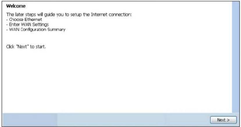
Click WAN Interface in the main Quick Setup screen to open the WAN Interface Quick Setup Wizard Welcome screen. Use these screens to configure an interface to connect to the Internet. Click Next.
Figure 27 WAN Interface Quick Setup Wizard
text_image
Welcome The later steps will guide you to setup the Internet connection: - Choose Ethernet - Enter WAN Settings - WAN Configuration Summary Click "Next" to start.5.2.1 Choose an Ethernet Interface
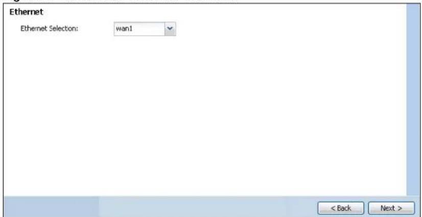
Select the Ethernet interface that you want to configure for a WAN connection and click Next.
Figure 28 Choose an Ethernet Interface
text_image
Ethernet Ethernet Selection: wan1 < Back Next >5.2.2 Select WAN Type
WAN Type Selection: Select the type of encapsulation this connection is to use. Choose Ethernet when the WAN port is used as a regular Ethernet.
Otherwise, choose PPPoE or PPTP for a dial-up connection according to the information from your ISP.
Figure 29 WAN Interface Setup: Step 2

text_image
WAN Interface Setup WAN Type Selection: Ethernet < Back Next >The screens vary depending on what encapsulation type you use. Refer to information provided by your ISP to know what to enter in each field. Leave a field blank if you don't have that information.
Note: Enter the Internet access information exactly as your ISP gave it to you.
5.2.3 Configure WAN IP Settings
Use this screen to select whether the interface should use a fixed or dynamic IP address.
Figure 30 WAN Interface Setup: Step 2

text_image
Interface WAN Interface: wan1 Zone:: WAN IP Address Assignment:: Static < Back Next >- WAN Interface: This is the interface you are configuring for Internet access.
• Zone: This is the security zone to which this interface and Internet connection belong. - IP Address Assignment: Select Auto If your ISP did not assign you a fixed IP address. Select Static if you have a fixed IP address.
5.2.4 ISP and WAN Connection Settings
Use this screen to configure the ISP and WAN interface settings. This screen is read-only if you select Ethernet and set the IP Address Assignment to Auto. If you set the IP Address Assignment to Static and/or select PPTP or PPPoE, enter the Internet access information exactly as your ISP gave it to you.
Figure 31 ISP and WAN Connection Settings: (PPTP Shown)

text_image
ISP Parameters Encapsulation: PPTP Authentication Type: ChapJAP User Name: Password: Retype to Confirm: Nailed-Up Idle timeout: 100 Seconds PPTP Configuration Bese Interface: wan1 Bese IP Address: 0.0.0.0 IP Subnet Mask: 255.255.255.0 Gateway IP Address: (Optional) Server IP: 0.0.0.0 Connection ID: (Optional) WAN Interface Setup WAN Interface: wan1_ppp Zone: WAN IP Address: 0.0.0.0 Gateway IP Address: (Optional) First DNS Server: Second DNS Server: < Back Save>The following table describes the labels in this screen.
Table 10 ISP and WAN Connection Settings
| LABEL DESCRIPTION | |
| ISP Parameter | This section appears if the interface uses a PPPoE or PPTP Internet connection. |
| Encapsulation This displays the type of Internet connection you are configuring. | |
| Authentication Type | Use the drop-down list box to select an authentication protocol for outgoing calls. Options are:CHAP/ PAP- Your UAG accepts either CHAP or PAP when requested by this remote node.CHAP- Your UAG accepts CHAP only.PAP- Your UAG accepts PAP only.MSCHAP- Your UAG accepts MSCHAP only.MSCHAP-V2- Your UAG accepts MSCHAP-V2 only. |
| User Name Type | the user name given to you by your ISP. You can use alphanumeric and -_ @$ . / characters, and it can be up to 31 characters long. |
| Password | Type the password associated with the user name above. Use up to 64 ASCII characters except the [] and ?. This field can be blank. |
| Retype to Confirm | Type your password again for confirmation. |
| Nailed-Up | Select Nailed-Up if you do not want the connection to time out. |
| Idle Timeout | Type the time in seconds that elapses before the router automatically disconnects from the PPPoE server. 0 means no timeout. |
| PPTP Configuration | This section only appears if the interface uses a PPPoE or PPTP Internet connection. |
| Base Interface | This displays the identity of the Ethernet interface you configure to connect with a modem or router. |
| Base IP Address Type the (static) IP address assigned to you by your ISP. | |
| IP Subnet Mask Type the subnet mask assigned to you by your ISP (if given). | |
| Server IP Type the IP address of the PPTP server. | |
| Connection ID | Enter the connection ID or connection name in this field. It must follow the "c:id" and "n:name" format. For example, C:12 or N:My ISP.This field is optional and depends on the requirements of your DSL modem.You can use alphanumeric and -_: characters, and it can be up to 31 characters long. |
| WAN Interface Setup | |
| WAN Interface | This displays the identity of the interface you configure to connect with your ISP. |
| Zone | This field displays to which security zone this interface and Internet connection will belong. |
| IP Address | This field is read-only when the WAN interface uses a dynamic IP address. If your WAN interface uses a static IP address, enter it in this field. |
| First DNS Server Second DNS Server | These fields only display for an interface with a static IP address. Enter the DNS server IP address(es) in the field(s) to the right.Leave the field as 0.0.0.0 if you do not want to configure DNS servers. If you do not configure a DNS server, you must know the IP address of a machine in order to access it.DNS (Domain Name System) is for mapping a domain name to its corresponding IP address and vice versa. The DNS server is extremely important because without it, you must know the IP address of a computer before you can access it. The UAG uses a system DNS server (in the order you specify here) to resolve domain names for VPN, DDNS and the time server. |
| Back Click Back to return to the previous screen. | |
| Next Click Next to continue. | |
5.2.5 Quick Setup Interface Wizard: Summary
This screen displays the WAN interface's settings.
Figure 32 Interface Wizard: Summary WAN (Ethernet Shown)
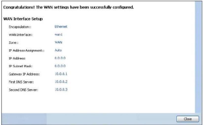
text_image
Congratulations! The WAN settings have been successfully configured. WAN Interface Setup Encapsulation:: Ethernet WAN Interface: want1 Zone: WAN IP Address Assignment: Auto IP Address: 0.0.0.0 IP Subnet Mask: 0.0.0.0 Gateway IP Address: 10.0.0.1 First DNS Server: 10.0.0.2 Second DNS Server: 10.0.0.3 CloseThe following table describes the labels in this screen.
Table 11 Interface Wizard: Summary WAN
| LABEL DESCRIPTION | |
| Encapsulation This | displays what encapsulation this interface uses to connect to the Internet. |
| Service Name | This field only appears for a PPPoE interface. It displays the PPPoE service name specified in the ISP account. |
| Server IP | This field only appears for a PPTP interface. It displays the IP address of the PPTP server. |
| User Name This is | the user name given to you by your ISP. |
| Nailed-Up | If No displays the connection will not time out. Yes means the UAG uses the idle timeout. |
| Idle Timeout | This is how many seconds the connection can be idle before the router automatically disconnects from the PPPoE server. 0 means no timeout. |
| Connection ID If you specified a connection ID, it displays here. | |
| WAN Interface | This identifies the interface you configure to connect with your ISP. |
| Zone | This field displays to which security zone this interface and Internet connection will belong. |
| IP Address Assignment | This field displays whether the WAN IP address is static or dynamic (Auto). |
| IP Address This field displays the WAN IP address. | |
| IP Subnet Mask | This field only appears for an Ethernet interface. It displays the interface's IP subnet mask. |
| Gateway IP Address | This field only appears for an Ethernet interface. It displays the IP address of the gateway. |
| First DNS Server Second DNS Server | If the IP Address Assignment is Static, these fields display the DNS server IP address(es). |
| Close | Click Close to exit the wizard. |
5.3 VPN Setup Wizard
Click VPN Setup in the main Quick Setup screen to open the VPN Setup Wizard Welcome screen.
Figure 33 VPN Setup Wizard
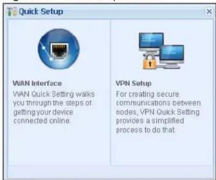
text_image
Quick Setup WAN Interface WAN Quick Setting walks you through the steps or getting your device connected online. VPN Setup For creating secure communications between nodes, VPN Quick Setting provides a simplified process to do that.5.3.1 Welcome
Use wizards to create Virtual Private Network (VPN) rules. After you complete the wizard, the Phase 1 rule settings appear in the VPN > IPSec VPN > VPN Gateway screen and the Phase 2 rule settings appear in the VPN > IPSec VPN > VPN Connection screen.
Figure 34 VPN Wizard Welcome
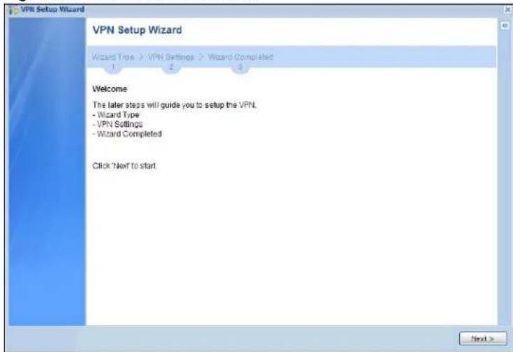
text_image
VPN Setup Wizard VPN Setup Wizard Wizard Type > VPN Settings > Wizard Completed Welcome The later steps will guide you to setup the VPN. - Wizard Type - VPN Settings - Wizard Completed Click 'Next to start.5.3.2 VPN Setup Wizard: Wizard Type
Choose Express to create a VPN rule with the default phase 1 and phase 2 settings to connect to another ZLD-based UAG using a pre-shared key.
Choose Advanced to change the default settings and/or use certificates instead of a pre-shared key to create a VPN rule to connect to another IPSec device.
Figure 35 VPN Setup Wizard: Wizard Type
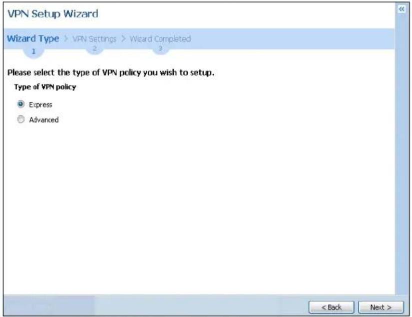
text_image
VPN Setup Wizard Wizard Type > VPN Settings > Wizard Completed Please select the type of VPN policy you wish to setup. Type of VPN policy Express Advanced < Back Next >5.3.3 VPN Express Wizard - Scenario
Click the Express radio button as shown in Figure 35 on page 58 to display the following screen.
Figure 36 VPN Express Wizard: Scenario

text_image
VPN Setup Wizard VPN Setup Wizard Wizard Type > VPN Settings > Wizard Completed 1 2 3 Express Settings Scenario Rule Name: WIZ_VPN Application Scenario: Site-to-site < Back Next >Rule Name: Type the name used to identify this VPN connection (and VPN gateway). You may use 1-31 alphanumeric characters, underscores (_), or dashes (-), but the first character cannot be a number. This value is case-sensitive.
Application Scenario: This shows the scenario that the UAG supports.
- Site-to-site - The remote IPSec device has a static IP address or a domain name. This UAG can initiate the VPN tunnel.
5.3.4 VPN Express Wizard - Configuration
Figure 37 VPN Express Wizard: Configuration

text_image
Express Settings Configuration Secure Gateway: IP/FQCN) Pre-Shared Key: Local Policy (IP/Mask) 0.0.0.0 / 255.255.255.0 Remote Policy (IP/Mask) 0.0.0.0 / 255.255.255.0 < Back Next >- Secure Gateway: Enter the WAN IP address or domain name of the remote IPSec device (secure gateway) to identify the remote IPSec router by its IP address or a domain name.
- Pre-Shared Key: Type the password. Both ends of the VPN tunnel must use the same password. Use 8 to 31 case-sensitive ASCII characters or 8 to 31 pairs of hexadecimal ("0-9", "A-F") characters. Proceed a hexadecimal key with "0x". You will receive a PYLD_MALFORMED (payload malformed) packet if the same pre-shared key is not used on both ends.
- Local Policy (IP/ Mask): Type the IP address of a computer on your network that can use the tunnel. You can also specify a subnet. This must match the remote IP address configured on the remote IPSec device.
- Remote Policy (IP/ Mask): Type the IP address of a computer behind the remote IPSec device. You can also specify a subnet. This must match the local IP address configured on the remote IPSec device.
5.3.5 VPN Express Wizard - Summary
This screen provides a read-only summary of the VPN tunnel's configuration and commands that you can copy and paste into another ZLD-based UAG's command line interface to configure it.
Figure 38 VPN Express Wizard: Summary
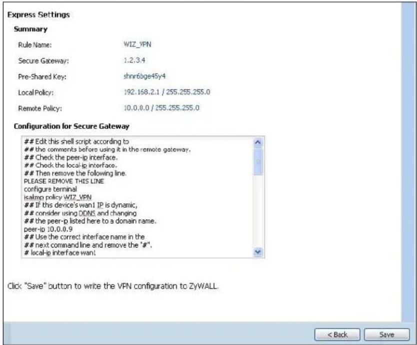
text_image
Express Settings Summary Rule Name: WIZ_VPN Secure Gateway: 1.2.3.4 Pre-Shared Key: shnr6bge45y4 Local Policy: 192.168.2.1 / 255.255.255.0 Remote Policy: 10.0.0.0 / 255.255.255.0 Configuration for Secure GatewayEdit this shell script according to
the comments before using it in the remote gateway.
Check the peer-ip interface.
Check the local-ip interface.
Then remove the following line.
PLEASE REMOVE THIS LINE configure terminal isalmp policy WIZ_VPNIf this device's wan1 IP is dynamic,
consider using DDNS and changing
the peer-p listed here to a domain name.
peer-ip 10.0.0.9Use the correct interface name in the
next command line and remove the "#",
local-ip interface want.
Click "Save" button to write the VPN configuration to ZyWALL. < Back Save- Rule Name: Identifies the VPN gateway policy.
- Secure Gateway: IP address or domain name of the remote IPSec device.
- Pre-Shared Key: VPN tunnel password. It identifies a communicating party during a phase 1 IKE negotiation.
- Local Policy: IP address and subnet mask of the computers on the network behind your UAG that can use the tunnel.
- Remote Policy: IP address and subnet mask of the computers on the network behind the remote IPSec device that can use the tunnel.
- Copy and paste the Configuration for Secure Gateway commands into another ZLD-based UAG's command line interface to configure it to serve as the other end of this VPN tunnel. You can also use a text editor to save these commands as a shell script file with a ".zysh" filename extension. Use the file manager to run the script in order to configure the VPN connection. See the commands reference guide for details on the commands displayed in this list.
5.3.6 VPN Express Wizard - Finish
Now the rule is configured on the UAG. The Phase 1 rule settings appear in the VPN > IPSec VPN > VPN Gateway screen and the Phase 2 rule settings appear in the VPN > IPSec VPN > VPN Connection screen.
Figure 39 VPN Express Wizard: Finish
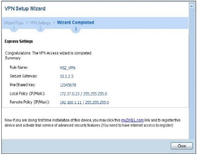
text_image
VPN Setup Wizard Wizard Type > VPN Settings > Wizard Completed 1 2 3 Express Settings Congratulations: The VPN Access wizard is completed Summary Rule Name: WIZ_VPN Secure Gateway: 10.1.2.3 Pre-Shared Key: 12345678 Local Policy (IP/Mask): 172.17.0.23 / 255.255.255.0 Remote Policy (IP/Mask): 192.168.1.11 / 255.255.255.0 Now if you are doing first time installation of this device, you may click this myZXEL.com link and to register this device and activate trial service of advanced security features. (You need to have internet access to register) CloseClick Close to exit the wizard.
5.3.7 VPN Advanced Wizard - Scenario
Click the Advanced radio button as shown in Figure 35 on page 58 to display the following screen.
Figure 40 VPN Advanced Wizard: Scenario
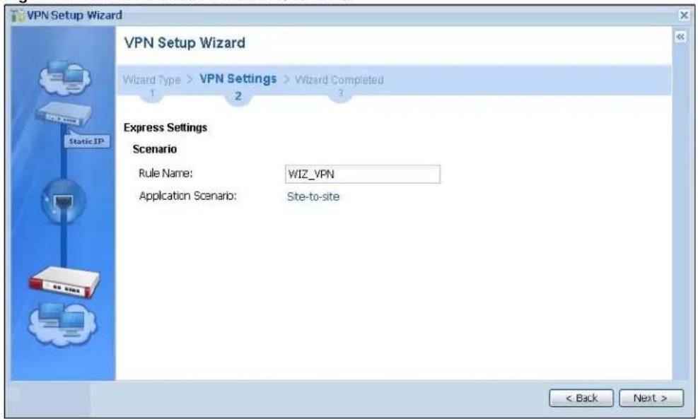
text_image
VPN Setup Wizard VPN Setup Wizard Wizard Type > VPN Settings > Wizard Completed 1 2 3 Express Settings Scenario Rule Name: WIZ_VPN Application Scenario: Site-to-site < Back Next >Rule Name: Type the name used to identify this VPN connection (and VPN gateway). You may use 1-31 alphanumeric characters, underscores (_), or dashes (-), but the first character cannot be a number. This value is case-sensitive.
Application Scenario: This shows the scenario that the UAG supports.
- Site-to-site - The remote IPSec device has a static IP address or a domain name. This UAG can initiate the VPN tunnel.
5.3.8 VPN Advanced Wizard - Phase 1 Settings
There are two phases to every IKE (Internet Key Exchange) negotiation – phase 1 (Authentication) and phase 2 (Key Exchange). A phase 1 exchange establishes an IKE SA (Security Association).
Figure 41 VPN Advanced Wizard: Phase 1 Settings
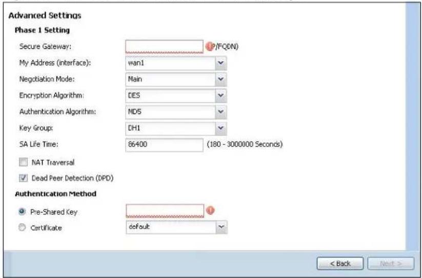
text_image
Advanced Settings Phase 1 Setting Secure Gateway: P/FQ0N My Address (interface): wan1 Negotiation Mode: Main Encryption Algorithm: DES Authentication Algorithm: MDS Key Group: DH1 SA Life Time: 86400 (180 - 3000000 Seconds) NAT Traversal Dead Peer Detection (DPD) Authentication Method Pre-Shared Key default < Back Next >- Secure Gateway: Any displays in this field if it is not configurable for the chosen scenario. Otherwise, enter the WAN IP address or domain name of the remote IPSec device (secure gateway) to identify the remote IPSec device by its IP address or a domain name. Use 0.0.0.0 if the remote IPSec device has a dynamic WAN IP address.
- My Address (interface): Select an interface from the drop-down list box to use on your UAG.
- Negotiation Mode: Select Main for identity protection. Select Aggressive to allow more incoming connections from dynamic IP addresses to use separate passwords.
Note: Multiple SAs connecting through a secure gateway must have the same negotiation mode.
- Encryption Algorithm: 3DES and AES use encryption. The longer the key, the higher the security (this may affect throughput). Both sender and receiver must use the same secret key, which can be used to encrypt and decrypt the message or to generate and verify a message authentication code. The DES encryption algorithm uses a 56-bit key. Triple DES (3DES) is a variation on DES that uses a 168-bit key. As a result, 3DES is more secure than DES. It also requires more processing power, resulting in increased latency and decreased throughput. AES128 uses a 128-bit key and is faster than 3DES. AES192 uses a 192-bit key, and AES256 uses a 256-bit key.
- Authentication Algorithm: MD5 gives minimal security and SHA512 gives the highest security. MD5 (Message Digest 5) and SHA (Secure Hash Algorithm) are hash algorithms used to authenticate packet data. The stronger the algorithm the slower it is.
- Key Group: DH5 is more secure than DH1 or DH2 (although it may affect throughput). DH1 (default) refers to Diffie-Hellman Group 1 a 768 bit random number. DH2 refers to Diffie-Hellman Group 2 a 1024 bit (1Kb) random number. DH5 refers to Diffie-Hellman Group 5 a 1536 bit random number.
- SA Life Time: Set how often the UAG renegotiates the IKE SA. A short SA life time increases security, but renegotiation temporarily disconnects the VPN tunnel.
- NAT Traversal: Select this if the VPN tunnel must pass through NAT (there is a NAT router between the IPSec devices).
Note: The remote IPSec device must also have NAT traversal enabled. See the help in the main IPSec VPN screens for more information.
- Dead Peer Detection (DPD) has the UAG make sure the remote IPSec device is there before transmitting data through the IKE SA. If there has been no traffic for at least 15 seconds, the UAG sends a message to the remote IPSec device. If it responds, the UAG transmits the data. If it does not respond, the UAG shuts down the IKE SA.
- Authentication Method: Select Pre-Shared Key to use a password or Certificate to use one of the UAG's certificates.
5.3.9 VPN Advanced Wizard - Phase 2
Phase 2 in an IKE uses the SA that was established in phase 1 to negotiate SAs for IPSec.
Figure 42 VPN Advanced Wizard: Phase 2 Settings
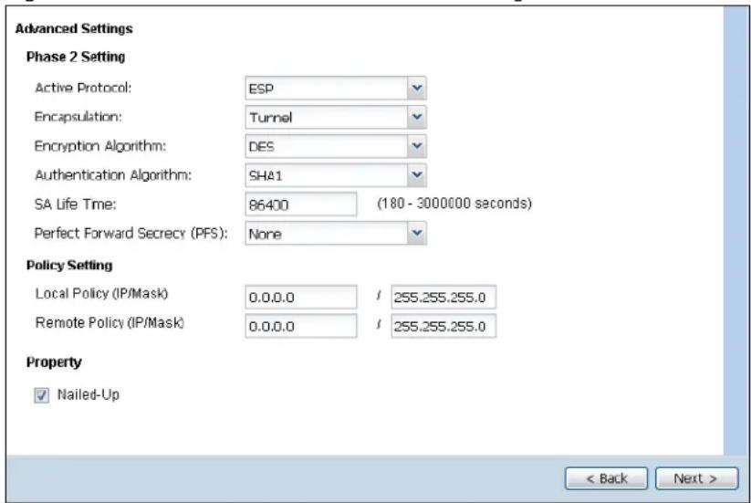
text_image
Advanced Settings Phase 2 Setting Active Protocol: ESP Encapsulation: Tunnel Encryption Algorithm: DES Authentication Algorithm: SHA1 SA Life Time: 86400 (180 - 3000000 seconds) Perfect Forward Secrecy (PFS): None Policy Setting Local Policy (IP/Mask) 0.0.0.0 / 255.255.255.0 Remote Policy (IP/Mask) 0.0.0.0 / 255.255.255.0 Property ✓ Nailed-Up < Back Next >• Active Protocol: ESP is compatible with NAT, AH is not.
- Encapsulation: Tunnel is compatible with NAT, Transport is not.
- Encryption Algorithm: 3DES and AES use encryption. The longer the AES key, the higher the security (this may affect throughput). Null uses no encryption.
- Authentication Algorithm: MD5 gives minimal security and SHA512 gives the highest security. MD5 (Message Digest 5) and SHA (Secure Hash Algorithm) are hash algorithms used to authenticate packet data. The stronger the algorithm the slower it is.
- SA Life Time: Set how often the UAG renegotiates the IKE SA. A short SA life time increases security, but renegotiation temporarily disconnects the VPN tunnel.
- Perfect Forward Secrecy (PFS): Disabling PFS allows faster IPSec setup, but is less secure. Select DH1, DH2 or DH5 to enable PFS. DH5 is more secure than DH1 or DH2 (although it may affect throughput). DH1 refers to Diffie-Hellman Group 1 a 768 bit random number. DH2 refers to Diffie-Hellman Group 2 a 1024 bit (1Kb) random number. DH5 refers to Diffie-Hellman Group 5 a 1536 bit random number (more secure, yet slower).
- Local Policy (IP/ Mask): Type the IP address of a computer on your network. You can also specify a subnet. This must match the remote IP address configured on the remote IPSec device.
- Remote Policy (IP/ Mask): Type the IP address of a computer behind the remote IPSec device. You can also specify a subnet. This must match the local IP address configured on the remote IPSec device.
- Nailed-Up: This displays for the site-to-site and remote access client role scenarios. Select this to have the UAG automatically renegotiate the IPSec SA when the SA life time expires.
5.3.10 VPN Advanced Wizard - Summary
This is a read-only summary of the VPN tunnel settings.
Figure 43 VPN Advanced Wizard: Summary

text_image
Advanced Settings Summary Rule Name: WIZ_VPN Secure Gateway: 10.1.2.5 Pre-Shared Key: 12345789 Local Policy (IP/Mask): 172.17.2.3 / 255.255.255.0 Remote Policy (IP/Mask): 192.168.2.5 / 255.255.255.0 Configuration for Secure GatewayEdit this shell script according to
the comments before using it in the remote gateway.
Check the peer-ip interface.
Check the local-ip interface.
Then remove the following line.
PLEASE REMOVE THIS LINE configure terminal isakmp policy WIZ_VPNIf this device's wan1 IP is dynamic,
consider using DDNS and changing
the peer-ip listed here to a domain name.
peer-ip 0.0.0.0Use the correct interface name in the
next command line and remove the "#".
Click "Save" button to write the VPN configuration to Device. < Back Save- Rule Name: Identifies the VPN connection (and the VPN gateway).
- Secure Gateway: IP address or domain name of the remote IPSec device.
- Pre-Shared Key: VPN tunnel password.
- Certificate: The certificate the UAG uses to identify itself when setting up the VPN tunnel.
- Local Policy: IP address and subnet mask of the computers on the network behind your UAG that can use the tunnel.
- Remote Policy: IP address and subnet mask of the computers on the network behind the remote IPSec device that can use the tunnel.
- Copy and paste the Configuration for Remote Gateway commands into another ZLD-based UAG's command line interface.
- Click Save to save the VPN rule.
5.3.11 VPN Advanced Wizard - Finish
Now the rule is configured on the UAG. The Phase 1 rule settings appear in the VPN > IPSec VPN > VPN Gateway screen and the Phase 2 rule settings appear in the VPN > IPSec VPN > VPN Connection screen.
Figure 44 VPN Wizard: Finish
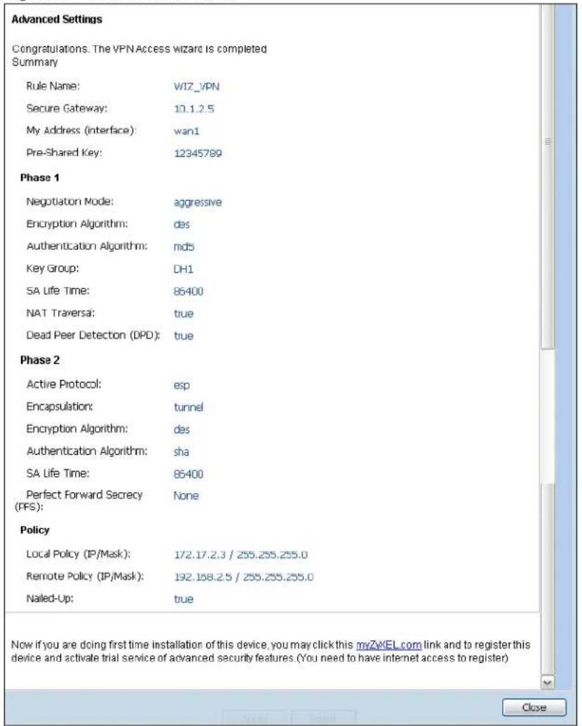
text_image
Advanced Settings Congratulations. The VPN Access wizard is completed Summary Rule Name: WIZ_VPN Secure Gateway: 10.1.2.5 My Address (interface): wan1 Pre-Shared Key: 12345789 Phase 1 Negotiation Mode: aggressive Encryption Algorithm: des Authentication Algorithm: md5 Key Group: DH1 SA Life Time: 86400 NAT Traversa: true Dead Peer Detection (DPD): true Phase 2 Active Protocol: esp Encapsulation: tunnel Encryption Algorithm: des Authentication Algorithm: sha SA Life Time: 86400 Perfect Forward Secrecy None (PPS): Policy Local Policy (IP/Mask): 172.17.2.3 / 255.255.255.0 Remote Policy (IP/Mask): 192.168.2.5 / 255.255.255.0 Nailed-Up: true Now if you are doing first time installation of this device, you may click this myZxEL.com link and to register this device and activate trial service of advanced security features (You need to have internet access to register) CloseClick Close to exit the wizard.
6.1 Overview
Use the Dashboard screens to check status information about the UAG.
6.1.1 What You Can Do in this Chapter
Use the Dashboard screens for the following.
- Use the main Dashboard screen (see Section 6.2 on page 66) to see the UAG's general device information, system status, system resource usage, licensed service status, and interface status. You can also display other status screens for more information.
- Use the VPN Status screen (see Section 6.2.4 on page 73) to look at the VPN tunnels that are currently established.
- Use the DHCP Table screen (see Section 6.2.5 on page 74) to look at the IP addresses currently assigned to DHCP clients and the IP addresses reserved for specific MAC addresses.
- Use the Number of Login Users screen (see Section 6.2.6 on page 75) to look at a list of the users currently logged into the UAG.
6.2 The Dashboard Screen
The Dashboard screen displays when you log into the UAG or click Dashboard in the navigation panel. The dashboard displays general device information, system status, system resource usage, licensed service status, and interface status in widgets that you can re-arrange to suit your needs. You can also collapse, refresh, and close individual widgets.
Figure 45 Dashboard

text_image
DASHBOARD Virtual Device ZyXEL UAG5100 UNIFIED ACCESS GATEWAY PWR CONSOLE 1 2 P1 P2 P3 P4 P5 SYS B A B C D E Device Information System Name: uag5100 Model Name: UAG5100 Serial Number: S122S19000011 MAC Address Range: CC:5D:4E:63:D4:54 ~ CC:5D:4E:63:D4:58 Firmware Version: V4.00(AAPN.0)b2/1.22/2013-12-05 17:32:48 System Resources CPU Usage 0 % Memory Usage 25 % Flash Usage 13 % USB Storage Usage 0/0 MB Active Sessions 67/80000 System Status System Uptime: 2 days, 04:21:05 Current Date/Time: 2014-01-08/05.33.06 GMT+00.00 VPN Status: 0 DHCP Table: 5 Current Login User: admin (unlimited / 00:29:59) Number of Login Users: 1 Boot Status: OK Drop-in Mode Status: Off Interface Status Summary Name Status Zone IP Addr/Netmask IP As... Action wan1 Down WAN 0.0.0.0/0.0.0.0 DHC... Renew wan2 Down WAN 0.0.0.0/0.0.0.0 DHC... Renew lan1 Down LAN1 172.16.0.1/25... Static n/a lan2 100... LAN2 172.17.0.1/25... Static n/a dmz Down DMZ 172.18.0.1/25... Static n/a Extension SlotExtension Slot Device Status
1 USB 1 none none 2 USB 2 none none Licensed Service StatusStatus Name Version Expiration
1 Default Extension User n/a 2 Default Managed AP Service n/a Top 5 StationAP MAC Max. Station Count AP Description
1 B0:B2:DC:6F:0E:47 2 AP-B0B2DC6F0E47 Top 5 IPv4 Firewall Rules that Blocked TrafficFrom To Description Hits
The Latest Alert LogsTime Priority Category Message Source Destin...
The following table describes the labels in this screen.
Table 12 Dashboard
| LABEL DESCRIPTION | |
| Widget Settings (A) | Use this link to open or close widgets by selecting/clearing the associated checkbox. |
| Up Arrow (B) Click | this to collapse a widget. It then becomes a down arrow. Click it again to enlarge the widget again. |
| Refresh Time Setting (C) | Set the interval for refreshing the information displayed in the widget. |
| Refresh Now (D) | Click this to update the widget's information immediately. |
| Close Widget (E) | Click this to close the widget. UseWidget Settingto re-open it. |
| Virtual Device | Hover your cursor over a LED, connected slot or Ethernet port to view details about the status of the UAG's front panel LEDs and connections. SeeSection 2.2.1 on page 34for LED descriptions. An unconnected interface or slot appears grayed out. |
| The following labels display when you hover your cursor over an Ethernet port or USB port. | |
| Name This field | displays the name of each interface. |
| Slot This field | displays the name of each extension slot. |
| Device | This field displays the name of the device connected to the USB port if one is connected. |
| Status | This field displays the current status of each interface or device installed in a slot. The possible values depend on what type of interface it is.Inactive- The Ethernet interface is disabled.Down- The Ethernet interface does not have any physical ports associated with it or the Ethernet interface is enabled but not connected.Speed / Duplex- The Ethernet interface is enabled and connected. This field displays the port speed and duplex setting (Full or Half).Ready- The USB port is connected. |
| Zone This field | displays the zone to which the interface is currently assigned. |
| IP Address/ Mask | This field displays the current IP address and subnet mask assigned to the interface. |
| Device Information | |
| System Name | This field displays the name used to identify the UAG on any network. Click the icon to open the screen where you can change it. |
| Model Name This field displays the model name of this UAG. | |
| Serial Number | This field displays the serial number of this UAG. The serial number is used for device tracking and control. |
| MAC Address Range | This field displays the MAC addresses used by the UAG. Each physical port has one MAC address. The first MAC address is assigned to physical port 1, the second MAC address is assigned to physical port 2, and so on. |
| Firmware Version | This field displays the version number and date of the firmware the UAG is currently running. Click the icon to open the screen where you can upload firmware. |
| System Status | |
| System Uptime | This field displays how long the UAG has been running since it last restarted or was turned on. |
| Current Date/ Time | This field displays the current date and time in the UAG. The format is yyyy-mm-dd hh:mm:ss. Click the icon to open the screen where you can configure the UAG's date and time. |
| VPN Status | This field displays the actual number of VPN tunnels up. Click this to look at the VPN tunnels that are currently established. SeeSection 6.2.4 on page 73. |
| DHCP Table | Click this to look at the IP addresses currently assigned to the UAG's DHCP clients and the IP addresses reserved for specific MAC addresses. SeeSection 6.2.5 on page 74. |
| Current Login User | This field displays the user name used to log in to the current session, the amount of reauthentication time remaining, and the amount of lease time remaining. |
| Number of Login Users | This field displays the number of users currently logged in to the UAG. Click the icon to pop-open a list of the users who are currently logged in to the UAG. |
| Boot Status This field displays details about the UAG's startup state.OK - The UAG started up successfully.Firmware update OK - A firmware update was successful.Problematic configuration after firmware update - The application of the configuration failed after a firmware upgrade.System default configuration - The UAG successfully applied the system default configuration. This occurs when the UAG starts for the first time or you intentionally reset the UAG to the system default settings.Fallback to lastgood configuration - The UAG was unable to apply the startup-config.conf configuration file and fell back to the lastgood.conf configuration file.Fallback to system default configuration - The UAG was unable to apply the lastgood.conf configuration file and fell back to the system default configuration file (system-default.conf).Booting in progress - The UAG is still applying the system configuration. | |
| Drop-in Mode Status | This field displays whether the UAG is working in drop-in mode.When the UAG is in drop-in mode, you can deploy it in your existing network without changing the network architecture and use its multiple WAN feature to connect to more than one ISP. See the CLI Reference Guide for how to use commands to set the UAG interfaces to work in drop-in mode. |
| Interface Status Summary | If an Ethernet interface does not have any physical ports associated with it, its entry is displayed in light gray text. |
| Name This field displays the name of each interface. | |
| Status This field displays the current status of each interface. The possible values depend on what type of interface it is.For Ethernet interfaces:Inactive - The Ethernet interface is disabled.Down - The Ethernet interface does not have any physical ports associated with it or the Ethernet interface is enabled but not connected.Up - The Ethernet interface is enabled and connected.For PPP interfaces:Connected - The PPP interface is connected.Disconnected - The PPP interface is not connected.If the PPP interface is disabled, it does not appear in the list. | |
| Zone This field displays the zone to which the interface is currently assigned. | |
| IP Addr/Netmask | This field displays the current IP address and subnet mask assigned to the interface. If the IP address is 0.0.0.0/0.0.0.0, the interface is disabled or did not receive an IP address and subnet mask via DHCP.If this interface is a member of an active virtual router, this field displays the IP address it is currently using. This is either the static IP address of the interface (if it is the master) or the management IP address (if it is a backup). |
| IP Assignment | This field displays how the interface gets its IP address. Static - This interface has a static IP address. DHCP Client - This Ethernet interface gets its IP address from a DHCP server. Dynamic - This PPP interface gets its IP address from a DHCP server. |
| Action Use this | field to get or to update the IP address for the interface. Click Renew to send a new DHCP request to a DHCP server. Click the Connect icon to have the UAG try to connect a PPPoE/PPTP interface. If the interface cannot use one of these ways to get or to update its IP address, this field displays n/ a. Click the Disconnect icon to stop a PPPoE/PPTP connection. |
| Extension Slot This | section of the screen displays the status of the USB ports. |
| # This field displays how many USB ports there are. | |
| Extension Slot | This field displays the name of each extension slot. |
| Device | This field displays the name of the device connected to the extension slot (or none if no device is detected). |
| Status | Ready - A USB storage device connected to the UAG is ready for the UAG to use. none - The UAG is unable to mount a USB storage device connected to the UAG. |
| Licensed Service Status | |
| # This shows how many licensed services there are. | |
| Status This is the current status of the license. | |
| Name This identifies the licensed service. | |
| Version This is the version number of the service. | |
| Expiration | If the service license is valid, this shows when it will expire. n/ a displays if the service license does not have a limited period of validity. 0 displays if the service is not licensed or has expired. |
| System Resources | |
| CPU Usage | This field displays what percentage of the UAG's processing capability is currently being used. Hover your cursor over this field to display the Show CPU Usage icon that takes you to a chart of the UAG's recent CPU usage. |
| Memory Usage | This field displays what percentage of the UAG's RAM is currently being used. Hover your cursor over this field to display the Show Memory Usage icon that takes you to a chart of the UAG's recent memory usage. |
| Flash Usage | This field displays what percentage of the UAG's onboard flash memory is currently being used. |
| USB Storage Usage | This field shows how much storage in the USB device connected to the UAG is in use. |
| Active Sessions | This field displays how many traffic sessions are currently open on the UAG. These are all sessions, established and non-established, that pass through/from/to/within the UAG. Hover your cursor over this field to display icons. Click the Detail icon to go to the Session Monitor screen to see details about the active sessions. Click the Show Active Sessions icon to display a chart of UAG's recent session usage. |
| AP Information This shows a summary of connected wireless Access Points (APs). | |
| All AP This section | displays a summary for all connected wireless APs. Click the link to go to theAP information > AP List screen. |
| Online Management AP | This displays the number of currently connected management APs. |
| Offline Management AP | This displays the number of currently offline managed APs. |
| Un-Management AP | This displays the number of non-managed APs. |
| All Station | This section displays a summary of connected stations. Click the link to go to the Station Info > Station List screen. |
| Station | This displays the number of stations currently connected to the network. |
| Top 5 Station Dis | plays the top 5 Access Points (AP) with the highest number of station (aka wireless client) connections. |
| # This field dis | plays the rank of the station. |
| AP MAC This field | displays the MAC address of the AP to which the station belongs. |
| Max. Station Count | This field displays the maximum number of wireless clients that have connected to this AP. |
| AP Description | This field displays the AP's description. The default description is "AP-" followed by the AP's MAC address. |
| Top 5 IPv4 Firewall Rules that blocked Traffic | This section displays the most triggered five firewall rules that caused the UAG to block. |
| # This is the entry's rank in the list of the most commonly triggered firewall rules. | |
| From | This shows the zone from which packets that triggered the firewall rule came. |
| To | This shows the zone to which packets that triggered the firewall rule went. |
| Description | This field displays the descriptive name (if any) of the triggered firewall rule. |
| Hits | This field displays how many times the firewall rule was triggered. |
| The Latest Alert Logs | This section of the screen displays recent logs generated by the UAG. |
| # This is the entry's rank in the list of alert logs. | |
| Time This field | displays the date and time the log was created. |
| Priority This field | displays the severity of the log. |
| Category | This field displays the type of log generated. |
| Message | This field displays the actual log message. |
| Source | This field displays the source address (if any) in the packet that generated the log. |
| Destination | This field displays the destination address (if any) in the packet that generated the log. |
6.2.1 The CPU Usage Screen
Use this screen to look at a chart of the UAG's recent CPU usage. To access this screen, click CPU Usage in the dashboard.
Figure 46 Dashboard > CPU Usage
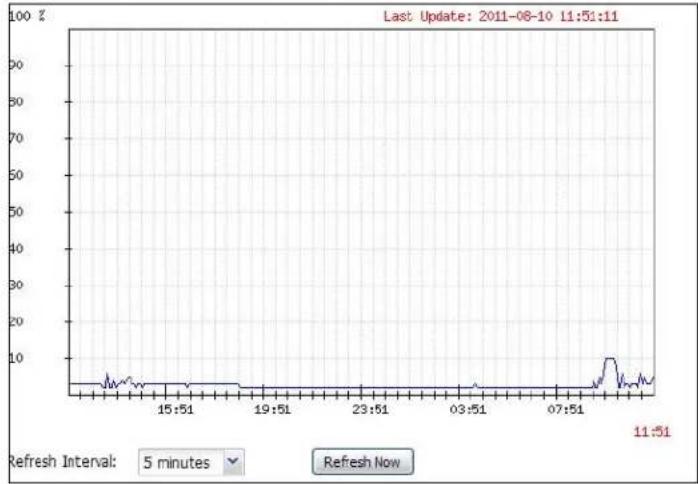
line
| Time | Value | | -------- | ----- | | 15:51 | ~5 | | 19:51 | ~5 | | 23:51 | ~5 | | 03:51 | ~5 | | 07:51 | ~5 | | 11:51 | ~5 |The following table describes the labels in this screen.
Table 13 Dashboard > CPU Usage
| LABEL DESCRIPTION | |
| The y-axis represents the percentage of CPU usage. | |
| The x-axis shows the time period over which the CPU usage occurred | |
| Refresh Interval Enter how often you want this window to be automatically updated. | |
| Refresh Now Click | this to update the information in the window right away. |
6.2.2 The Memory Usage Screen
Use this screen to look at a chart of the UAG's recent memory (RAM) usage. To access this screen, click Memory Usage in the dashboard.
Figure 47 Dashboard > Memory Usage

line
| Time | Value | | -------- | ----- | | 15:52 | 37 | | 11:52 | 37 |The following table describes the labels in this screen.
Table 14 Dashboard > Memory Usage
| LABEL DESCRIPTION | |
| The y-axis represents the percentage of RAM usage. | |
| The x-axis shows the time period over which the RAM usage occurred | |
| Refresh Interval Enter how often you want this window to be automatically updated. | |
| Refresh Now Click this to update the information in the window right away. | |
6.2.3 The Active Sessions Screen
Use this screen to look at a chart of the UAG's recent traffic session usage. To access this screen, click Show Active Sessions in the dashboard.
Figure 48 Dashboard > Show Active Sessions

line
| Time | Sessions | | -------- | -------- | | 08:44 | 0 | | 12:44 | 0 | | 16:44 | 0 | | 20:44 | 0 | | 00:44 | 5 | | 04:44 | 5 |The following table describes the labels in this screen.
Table 15 Dashboard > Show Active Sessions
| LABEL DESCRIPTION | |
| Sessions The y-axis represents the number of session. | |
| The x-axis shows the time period over which the session usage occurred | |
| Refresh Interval Enter how often you want this window to be automatically updated. | |
| Refresh Now Click this to update the information in the window right away. | |
6.2.4 The VPN Status Screen
Use this screen to look at the VPN tunnels that are currently established. To access this screen, click VPN Status in System Status in the dashboard.
Figure 49 Dashboard > System Status > VPN Status

text_image
VPN StatusName ▲ Encapsulation Algorithm
Refresh Interval: 5 minutes ✓ Refresh NowThe following table describes the labels in this screen.
Table 16 Dashboard > VPN Status
| LABEL DESCRIPTION | |
| # This field is a sequential value, and it is not associated with a specific SA. | |
| Name This field displays the name of the IPSec SA. | |
| Encapsulation This field displays how the IPSec SA is encapsulated. | |
| Algorithm | This field displays the encryption and authentication algorithms used in the SA. |
| Refresh Interval Select how often you want this window to be updated automatically. | |
| Refresh Now Click this to update the information in the window right away. | |
6.2.5 The DHCP Table Screen
Use this screen to look at the IP addresses currently assigned to DHCP clients and the IP addresses reserved for specific MAC addresses. To access this screen, click DHCP Table in System Status in the dashboard.
Figure 50 Dashboard > DHCP Table
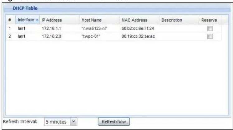
text_image
DHCP TableInterface IP Address Host Name MAC Address Description Reserve
1 lan1 172.16.1.1 "nwa5123-nl" b0.b2:dc:6e:7f:24 2 lan1 172.16.2.0 "twpc-01" 00:19:cb:32:be:ac Refresh Interval: 5 minutes Refresh NowThe following table describes the labels in this screen.
Table 17 Dashboard > DHCP Table
| LABEL DESCRIPTION | |
| # | This field is a sequential value, and it is not associated with a specific entry. |
| Interface | This field identifies the interface that assigned an IP address to a DHCP client. |
| IP Address | This field displays the IP address currently assigned to a DHCP client or reserved for a specific MAC address. Click the column's heading cell to sort the table entries by IP address. Click the heading cell again to reverse the sort order. |
| Host Name This field displays the name used to identify this device on the network (the computer name). The UAG learns these from the DHCP client requests. “None” shows here for a static DHCP entry. | |
| MAC Address | This field displays the MAC address to which the IP address is currently assigned or for which the IP address is reserved. Click the column's heading cell to sort the table entries by MAC address. Click the heading cell again to reverse the sort order. |
| Description | For a static DHCP entry, the host name or the description you configured shows here. This field is blank for dynamic DHCP entries. |
| Reserve | If this field is selected, this entry is a static DHCP entry. The IP address is reserved for the MAC address.If this field is clear, this entry is a dynamic DHCP entry. The IP address is assigned to a DHCP client.To create a static DHCP entry using an existing dynamic DHCP entry, select this field.To remove a static DHCP entry, clear this field. |
| Refresh Interval | Enter how often you want this window to be automatically updated. |
| Refresh Now | Click this to update the information in the window right away. |
6.2.6 The Number of Login Users Screen
Use this screen to look at a list of the users currently logged into the UAG. Users who close their browsers without logging out are still shown as logged in here. To access this screen, click Number of Login Users in System Status in the dashboard.
Figure 51 Dashboard > Number of Login Users
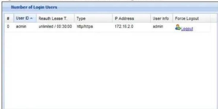
text_image
Number of Login UsersUser ID ▲ Reauth Lease T. Type P Address User info Force Logout
0 admin unlimited / 00:30:00 http/https 172.16.2.0 admin LOGOUTThe following table describes the labels in this screen.
Table 18 Dashboard > Number of Login Users
| LABEL DESCRIPTION | |
| # This field is a sequential value and is not associated with any entry. | |
| User ID | This field displays the user name of each user who is currently logged in to the UAG. |
| Reauth Lease T. | This field displays the amount of reauthentication time remaining and the amount of lease time remaining for each user. See Chapter 32 on page 325 for more information. |
| Type This field displays the way the user logged in to the UAG. | |
| IP address This field displays the IP address of the computer used to log in to the UAG. | |
| User Info | This field displays the types of user accounts the UAG uses. If the user type is ext-user (external user), this field will show its external-group information when you move your mouse over it.If the external user matches two external-group objects, both external-group object names will be shown. |
| Force Logout Click | this icon to end a user's session. |
7.1 Overview
Use the Monitor screens to check status and statistics information.
7.1.1 What You Can Do in this Chapter
Use the Monitor screens for the following.
- Use the System Status > Port Statistics screen (see Section 7.2 on page 78) to look at packet statistics for each physical port.
- Use the System Status > Port Statistics > Graph View screen (see Section 7.2 on page 78) to look at a line graph of packet statistics for each physical port.
- Use the System Status > Interface Status screen (see Section 7.3 on page 80) to see all of the UAG's interfaces and their packet statistics.
- Use the System Status > Traffic Statistics screen (see Section 7.4 on page 83) to start or stop data collection and view statistics.
- Use the System Status > Session Monitor screen (see Section 7.5 on page 85) to view sessions by user or service.
- Use the System Status > DDNS Status screen (see Section 7.6 on page 87) to view the status of the UAG's DDNS domain names.
- Use the System Status > IP/ MAC Binding screen (see Section 7.7 on page 88) to view a list of devices that have received an IP address from UAG interfaces with IP/MAC binding enabled.
- Use the System Status > Login Users screen (see Section 7.8 on page 89) to look at a list of the users currently logged into the UAG.
- Use the System Status > UPnP Port Status screen (see Section 7.9 on page 90) to look at a list of the NAT port mapping rules that UPnP creates on the UAG.
- Use the System Status > USB Storage screen (see Section 7.10 on page 91) to view information about a connected USB storage device.
- Use the System Status > Dynamic Guest screen (see Section 7.11 on page 92) to look at a list of the guest user accounts, which are created automatically and allowed to access the UAG's services for a certain period of time.
- Use the AP Information > AP List screen (see Section 7.12 on page 94) to view which APs are currently connected to the UAG.
- Use the AP Information > Radio List screen (see Section 7.13 on page 96) to view statistics about the wireless radio transmitters in each of the APs connected to the UAG.
- Use the Station Info > Station List screen (see Section 7.14 on page 99) to view statistics pertaining to the connected stations (or “wireless clients”).
-
Use the Printer Status screen (see Section 7.15 on page 100) to view information about the connected statement printers.
-
Use the VPN 1-1 Mapping screen (see Section 7.16 on page 101) to view the status of the active users to which the UAG applied a VPN 1-1 mapping rule.
- Use the VPN 1-1 Mapping > Statistics screen (see Section 7.16.1 on page 102) to display statistics for each of the VPN 1-1 mapping rules.
- Use the VPN Monitor > IPSec screen (Section 7.18 on page 104) to display and manage active IPSec SAs.
- Use the Log > View Log screen (see Section 7.18 on page 104) to view the UAG's current log messages. You can change the way the log is displayed, you can e-mail the log, and you can also clear the log in this screen.
- Use the Log > View AP Log screen (see Section 7.18.1 on page 107) to view the UAG's current wireless AP log messages.
- Use the Log > Dynamic Users Log screen (see Section 7.18.2 on page 109) to view the UAG's dynamic guest account log messages.
7.2 The Port Statistics Screen
Use this screen to look at packet statistics for each Gigabit Ethernet port. To access this screen, click Monitor > System Status > Port Statistics.
Figure 52 Monitor > System Status > Port Statistics
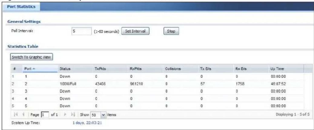
text_image
Port Statistics General Settings Poll Interval: 5 (1-60 seconds) Set Interval Stop Statistics Table Switch To Graphic ViewPort ~ Status TxPlts RxPlts Collisions Tx E/s Rx E/s Up Time
1 1 Down 0 0 0 0 0 00:00:00 2 2 100M/Full 43408 961210 0 57 1758 48:07:52 3 3 Down 0 0 0 0 0 00:00:00 4 4 Down 0 0 0 0 0 00:00:00 5 5 Down 0 0 0 0 0 00:00:00 Page 1 of 1 Show 50 Items Displaying 1 - 5 of 5 System Up Time: 1 days, 22:03:21The following table describes the labels in this screen.
Table 19 Monitor > System Status > Port Statistics
| LABEL DESCRIPTION | |
| Poll Interval | Enter how often you want this window to be updated automatically, and click Set Interval. |
| Set Interval | Click this to set the Poll Interval the screen uses. |
| Stop Click this to stop the window from updating automatically. You can start it again by setting the Poll Interval and clicking Set Interval. | |
| Switch to Graphic View | Click this to display the port statistics as a line graph. |
| # This field displays the port's number in the list. | |
| Port This field displays the physical port number. | |
| Status This field d | splays the current status of the physical port. |
| Down - The physical port is not connected. | |
| Speed / Duplex - The physical port is connected. This field displays the port speed and duplex setting (Full or Half). | |
| TxPkts | This field displays the number of packets transmitted from the UAG on the physical port since it was last connected. |
| RxPkts This field d | displays the number of packets received by the UAG on the physical port since it was last connected. |
| Collisions This field | displays the number of collisions on the physical port since it was last connected. |
| Tx B/s | This field displays the transmission speed, in bytes per second, on the physical port in the one-second interval before the screen updated. |
| Rx B/s | This field displays the reception speed, in bytes per second, on the physical port in the one-second interval before the screen updated. |
| Up Time This field | displays how long the physical port has been connected. |
| System Up Time | This field displays how long the UAG has been running since it last restarted or was turned on. |
7.2.1 The Port Statistics Graph Screen
Use this screen to look at a line graph of packet statistics for each physical port. To access this screen, click Port Statistics in the Status screen and then the Switch to Graphic View Button.
Figure 53 Monitor > System Status > Port Statistics > Switch to Graphic View

line
| Time | TX | RX | | -------- | ----- | ----- | | 00:27 | 433.6 | 162.6 |The following table describes the labels in this screen.
Table 20 Monitor > System Status > Port Statistics > Switch to Graphic View
| LABEL DESCRIPTION | |
| Refresh Interval Enter how often you want this window to be automatically updated. | |
| Refresh Now Click this to update the information in the window right away. | |
| Port Selection | Select the number of the physical port for which you want to display graphics. |
| Switch to Grid View | Click this to display the port statistics as a table. |
| Kbps The y-axis represents the speed of transmission or reception. | |
| time | The x-axis shows the time period over which the transmission or reception occurred |
| TX | This line represents traffic transmitted from the UAG on the physical port since it was last connected. |
| RX | This line represents the traffic received by the UAG on the physical port since it was last connected. |
| Last Update | This field displays the date and time the information in the window was last updated. |
| System Up Time | This field displays how long the UAG has been running since it last restarted or was turned on. |
7.3 The Interface Status Screen
This screen lists all of the UAG's interfaces and gives packet statistics for them. Click Monitor > System Status > Interface Status to access this screen.
Figure 54 Monitor > System Status > Interface Status
| Interface Summary | |||||||
| Interface Status | |||||||
| Name | Port | Status | Zone | IP Addr/Netmask | IP Assign... | Services | Action |
| wan1 | P1 | Down | WAN | 0.0.0.0 / 0.0.0.0 | DHCP cli... | n/a | Renew |
| wan1... | P1 | Inactive | WAN | 0.0.0.0 / 0.0.0.0 | Dynamic | n/a | n/a |
| wan2 | P2 | Down | WAN | 0.0.0.0 / 0.0.0.0 | DHCP cli... | n/a | Renew |
| wan2... | P2 | Inactive | WAN | 0.0.0.0 / 0.0.0.0 | Dynamic | n/a | n/a |
| lan1 | P3 | Down | LAN1 | 172.16.0.1 / 255.255.0.0 | Static | DHCP s... | n/a |
| lan1... | P3 | Inactive | n/a | 0.0.0.0 / 0.0.0.0 | Dynamic | n/a | n/a |
| lan2 | P4 | 100M/Full | LAN2 | 172.17.0.1 / 255.255.0.0 | Static | DHCP s... | n/a |
| lan2... | P4 | Inactive | n/a | 0.0.0.0 / 0.0.0.0 | Dynamic | n/a | n/a |
| dmz | P5 | Down | DMZ | 172.18.0.1 / 255.255.0.0 | Static | DHCP s... | n/a |
| dmz... | P5 | Inactive | n/a | 0.0.0.0 / 0.0.0.0 | Dynamic | n/a | n/a |
Each field is described in the following table.
Table 21 Monitor > System Status > Interface Status
| LABEL DESCRIPTION | |
| Interface Status | |
| Expand/Close | Click this button to show or hide statistics for all the virtual interfaces on top of the Ethernet interfaces. |
| Name | This field displays the name of each interface. If there is an Expand icon (plus-sign) next to the name, click this to look at the status of virtual interfaces on top of this interface. |
| Port | This field displays the physical port number. If an Ethernet interface does not have any physical ports associated with it, this field displays n/ a. |
| Status | This field displays the current status of each interface. The possible values depend on what type of interface it is.For Ethernet interfaces:Inactive- The Ethernet interface is disabled.Down- The Ethernet interface does not have any physical ports associated with it or the Ethernet interface is enabled but not connected.Speed/ Duplex- The Ethernet interface is enabled and connected. This field displays the port speed and duplex setting (Full or Half).Port Group Inactive- The Ethernet interface does not have any physical ports associated with it.Port Group Up- The Ethernet interface is part of a port group and is connected.Port Group Down- The Ethernet interface is part of a port group and is not connected.For virtual interfaces, this field always displaysUpor Down. If the virtual interface is disabled, it displays Inactive.For VLAN and bridge interfaces, this field always displaysUpor Down. If the VLAN or bridge interface is disabled, it displays Inactive.For PPP interfaces:Inactive- The PPP interface is disabled-connected- The PPP interface is connected.Disconnected- The PPP interface is not connected. |
| Zone | This field displays the zone to which the interface is assigned. |
| IP Addr/Netmask | This field displays the current IP address and subnet mask assigned to the interface. If the IP address and subnet mask are 0.0.0.0, the interface is disabled or did not receive an IP address and subnet mask via DHCP. |
| IP Assignment | This field displays how the interface gets its IP address.Static- This interface has a static IP address.DHCP Client- This interface gets its IP address from a DHCP server. |
| Services | This field lists which services the interface provides to the network. Examples include DHCP relay, and DHCP server. This field displays n/a if the interface does not provide any services to the network. |
| Action | Use this field to get or to update the IP address for the interface. ClickRenewto send a new DHCP request to a DHCP server. ClickConnectto try to connect a PPPoE/PPTP interface. If the interface cannot use one of these ways to get or to update its IP address, this field displays n/a. |
| Interface Statistics | This table provides packet statistics for each interface. |
| Refresh Click this | button to update the information in the screen. |
| Expand/Close | Click this button to show or hide statistics for all the virtual interfaces on top of the Ethernet interfaces. |
| Name | This field displays the name of each interface. If there is aExpandicon (plus-sign) next to the name, click this to look at the statistics for virtual interfaces on top of this interface. |
| TxPkts This field displays the number of packets transmitted from the UAG on the interface since it was last connected. | |
| RxPkts | This field displays the number of packets received by the UAG on the interface since it was last connected. |
| Tx B/s This field displays the transmission speed, in bytes per second, on the interface in the one-second interval before the screen updated. | |
| Rx B/s | This field displays the reception speed, in bytes per second, on the interface in the one-second interval before the screen updated. |
7.4 The Traffic Statistics Screen
Click Monitor > System Status > Traffic Statistics to display the Traffic Statistics screen. This screen provides basic information about the following for example:
- Most-visited Web sites and the number of times each one was visited. This count may not be accurate in some cases because the UAG counts HTTP GET packets. Please see Table 22 on page 84 for more information.
- Most-used protocols or service ports and the amount of traffic on each one
• LAN IP with heaviest traffic and how much traffic has been sent to and from each one
You use the Traffic Statistics screen to tell the UAG when to start and when to stop collecting information for these reports. You cannot schedule data collection; you have to start and stop it manually in the Traffic Statistics screen.
Figure 55 Monitor > System Status > Traffic Statistics
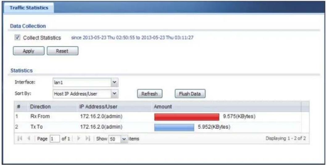
text_image
Traffic Statistics Data Collection ✓ Collect Statistics since 2013-05-23 Thu 02:50:55 to 2013-05-23 Thu 03:11:27 Apply Reset Statistics Interface: lan1 Sort By: Host IP Address/User Refresh Flush DataDirection IP Address/User Amount
1 Rx From 172.16.2.0(admin) 9.575(KBytes) 2 Tx To 172.16.2.0(admin) 5.952(KBytes) Page 1 of 1 Show 50 items Displaying 1 - 2 of 2There is a limit on the number of records shown in the report. Please see Table 23 on page 85 for more information. The following table describes the labels in this screen.
Table 22 Monitor > System Status > Traffic Statistics
| LABEL DESCRIPTION | |
| Data Collection | |
| Collect Statistics | Select this to have the UAG collect data for the report. If the UAG has already been collecting data, the collection period displays to the right. The progress is not tracked here real-time, but you can click the Refresh button to update it. |
| Apply | Click Apply to save your changes back to the UAG. |
| Reset | Click Reset to return the screen to its last-saved settings. |
| Statistics | |
| Interface | Select the interface from which to collect information. You can collect information from Ethernet, VLAN, bridge and PPPoE/PPTP interfaces. |
| Top Select the type | of report to display. Choices are:Host IP Address/ User - displays the IP addresses or users with the most traffic and how much traffic has been sent to and from each one.Service/ Port - displays the most-used protocols or service ports and the amount of traffic for each one.Web Site Hits - displays the most-visited Web sites and how many times each one has been visited.Each type of report has different information in the report (below). |
| Refresh Click this button to update the report display. | |
| Flush Data | Click this button to discard all of the screen's statistics and update the report display. |
| These fields are available when the Top is Host IP Address/ User. | |
| # This field is the rank of each record. The IP addresses and users are sorted by the amount of traffic. | |
| Direction This field indicates whether the IP address or user is sending or receiving traffic.RX From- traffic is coming from the IP address or user to the UAG.Tx To - traffic is going from the UAG to the IP address or user. | |
| IP Address/User | This field displays the IP address or user in this record. The maximum number of IP addresses or users in this report is indicated in Table 23 on page 85. |
| Amount This field displays how much traffic was sent or received from the indicated IP address or user. If the Direction is RX From, a red bar is displayed; if the Direction is Tx To, a blue bar is displayed. The unit of measure is bytes, Kbytes, Mbytes or Gbytes, depending on the amount of traffic for the particular IP address or user. The count starts over at zero if the number of bytes passes the byte count limit. See Table 23 on page 85. | |
| These fields are available when the Top is Service/Port. | |
| # | This field is the rank of each record. The protocols and service ports are sorted by the amount of traffic. |
| Service/Port | This field displays the service and port in this record. The maximum number of services and service ports in this report is indicated in Table 23 on page 85. |
| Protocol This field indicates what protocol the service was using. | |
| Direction | This field indicates whether the indicated protocol or service port is sending or receiving traffic.Ingress- traffic is coming into the router through the interfaceEgress- traffic is going out from the router through the interface |
| Amount | This field displays how much traffic was sent or received from the indicated service / port. If the Direction is Ingress, a red bar is displayed; if the Direction is Egress, a blue bar is displayed. The unit of measure is bytes, Kbytes, Mbytes, Gbytes, or Tbytes, depending on the amount of traffic for the particular protocol or service port. The count starts over at zero if the number of bytes passes the byte count limit. See Table 23 on page 85. |
| These fields are available when the Top is Web Site Hits. | |
| # | This field is the rank of each record. The domain names are sorted by the number of hits. |
| Web Site | This field displays the domain names most often visited. The UAG counts each page viewed on a Web site as another hit. The maximum number of domain names in this report is indicated in Table 23 on page 85. |
| Hits This field displays how many hits the Web site received. The UAG counts hits by counting HTTP GET packets. Many Web sites have HTTP GET references to other Web sites, and the UAG counts these as hits too. The count starts over at zero if the number of hits passes the hit count limit. See Table 23 on page 85. | |
The following table displays the maximum number of records shown in the report, the byte count limit, and the hit count limit.
Table 23 Maximum Values for Reports
| LABEL DESCRIPTION | |
| Maximum Number of Records | 20 |
| Byte Count Limit 2 | ^64 bytes; this is just less than 17 million terabytes. |
| Hit Count Limit 2 | ^64 hits; this is over 1.8 × 10^19 hits. |
7.5 The Session Monitor Screen
The Session Monitor screen displays information about all established sessions that pass through the UAG for debugging or statistical analysis. It is not possible to manage sessions in this screen. The following information is displayed.
- User who started the session
- Protocol or service port used
- Source address
- Destination address
• Number of bytes received (so far)
• Number of bytes transmitted (so far)
• Duration (so far)
You can look at all the active sessions by user, service, source IP address, or destination IP address. You can also filter the information by user, protocol / service or service group, source address, and/or destination address and view it by user.
Click Monitor > System Status > Session Monitor to display the following screen.
Figure 56 Monitor > System Status > Session Monitor

text_image
Session Monitor Session View: all sessions Refresh User: Service: any Source Address: Destination Address: SearchUser Service Source Destination Rx Tx Duration
1 admin HTTP 172.16.2.0.46... 192.13.5.248... 430 Bytes 882 Bytes 0 2 admin HTTP 172.16.2.0.46... 192.13.5.248... 431 Bytes 883 Bytes 0 3 admin HTTP 172.16.2.0.46... 192.13.5.248... 3.212 KBytes 1.021 KBytes 0 4 admin HTTP 172.16.2.0.46... 192.13.5.248... 805 Bytes 541 Bytes 1 5 admin HTTP 172.16.2.0.45... 192.13.5.248... 4.054 KBytes 1.501 KBytes 12 Page 1 of 1 Show 50 items Displaying 1 - 5 of 5The following table describes the labels in this screen.
Table 24 Monitor > System Status > Session Monitor
| LABEL DESCRIPTION | |
| View Select how you want the information to be displayed. Choices are:sessions by users - display all active sessions grouped by user.sessions by services - display all active sessions grouped by service or protocol.sessions by source IP - display all active sessions grouped by source IP address.sessions by destination IP - display all active sessions grouped by destination IP address.all sessions - filter the active sessions by the User, Service, Source Address, and Destination Address, and display each session individually (sorted by user). | |
| Refresh | Click this button to update the information on the screen. The screen also refreshes automatically when you open and close the screen. |
| The User, Service, Source Address, and Destination Address fields display if you view all sessions. Select your desired filter criteria and click the Search button to filter the list of sessions. | |
| LABEL | DESCRIPTION |
| User | This field displays whenViewis set toall sessions. Type the user whose sessions you want to view. It is not possible to type part of the user name or use wildcards in this field; you must enter the whole user name. |
| Service | This field displays whenViewis set toall sessions. Select the service or service group whose sessions you want to view. The UAG identifies the service by comparing the protocol and destination port of each packet to the protocol and port of each services that is defined. (SeeChapter 35 on page 359for more information about services.) |
| Source | This field displays whenViewis set toall sessions. Type the source IP address whose sessions you want to view. You cannot include the source port. |
| Destination | This field displays whenViewis set toall sessions. Type the destination IP address whose sessions you want to view. You cannot include the destination port. |
| Search | This button displays whenViewis set toall sessions. Click this button to update the information on the screen using the filter criteria in theUser, Service, Source Address, andDestination Addressfields. |
| Active Sessions This is the total number of active sessions that matched the search criteria. | |
| Show | Select the number of active sessions displayed on each page. You can use the arrow keys on the right to change pages. |
| User This field displays the user in each active session.If you are looking at thesessions by users(or all sessions) report, click + or - to display or hide details about a user's sessions. | |
| Service This field displays the protocol used in each active session.If you are looking at thesessions by servicesreport, click + or - to display or hide details about a protocol's sessions. | |
| Source This field displays the source IP address and port in each active session.If you are looking at thesessions by source IP report, click + or - to display or hide details about a source IP address's sessions. | |
| Destination | This field displays the destination IP address and port in each active session.If you are looking at thesessions by destination IP report, click + or - to display or hide details about a destination IP address's sessions. |
| Rx | This field displays the amount of information received by the source in the active session. |
| Tx This field displays the amount of information transmitted by the source in the active session. | |
| Duration | This field displays the length of the active session in seconds. |
7.6 The DDNS Status Screen
The DDNS Status screen shows the status of the UAG's DDNS domain names. Click Monitor > System Status > DDNS Status to open the following screen.
Figure 57 Monitor > System Status > DDNS Status
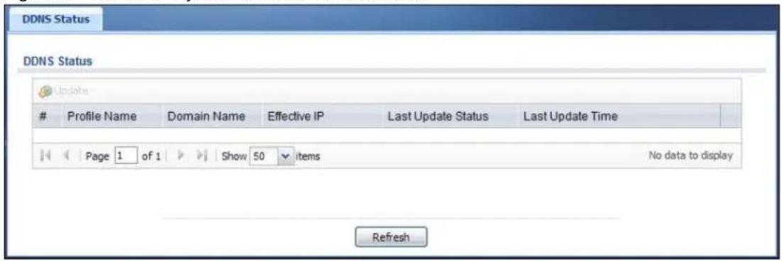
text_image
DDNS Status DDNS StatusProfile Name Domain Name Effective IP Last Update Status Last Update Time
Page 1 of 1 Show 50 items No data to display RefreshThe following table describes the labels in this screen.
Table 25 Monitor > System Status > DDNS Status
| LABEL DESCRIPTION | |
| Update Click this to | have the UAG update the profile to the DDNS server. The UAG attempts to resolve the IP address for the domain name. |
| Profile Name This field displays the descriptive profile name for this entry. | |
| Domain Name This field displays each domain name the UAG can route. | |
| Effective IP This is the (resolved) IP address of the domain name. | |
| Last Update Status | This shows whether the last attempt to resolve the IP address for the domain name was successful or not. Updating means the UAG is currently attempting to resolve the IP address for the domain name. |
| Last Update Time This shows when the last attempt to resolve the IP address for the domain name occurred (in year-month-day hour:minute:second format). | |
7.7 The IP/MAC Binding Monitor Screen
Click Monitor > System Status > IP/ MAC Binding to open the IP/ MAC Binding Monitor screen. This screen lists the devices that have received an IP address from UAG interfaces with IP/ MAC binding enabled and have ever established a session with the UAG. Devices that have never established a session with the UAG do not display in the list.
Figure 58 Monitor > System Status > IP/MAC Binding
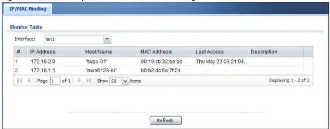
text_image
IP/MAC Binding Monitor Table Interface: lan1IP Address Host Name MAC Address Last Access Description
1 172.16.2.0 "twpc-01" 00:19:cb:32:be:ac Thu May 23 03:21:04... 2 172.16.1.1 "nwa5123-nl" b0:b2:dc:6e:7f:24 Page 1 of 1 Show 50 items Displaying 1 - 2 of 2 RefreshThe following table describes the labels in this screen.
Table 26 Monitor > System Status > IP/MAC Binding
| LABEL DESCRIPTION | |
| Interface | Select a UAG interface that has IP/MAC binding enabled to show to which devices it has assigned an IP address. |
| # This is the index | number of an IP/MAC binding entry. |
| IP Address | This is the IP address that the UAG assigned to a device. |
| Host Name | This field displays the name used to identify this device on the network (the computer name). The UAG learns these from the DHCP client requests. |
| MAC Address | This field displays the MAC address to which the IP address is currently assigned. |
| Last Access | This is when the device last established a session with the UAG through this interface. |
| Description This field | d displays the descriptive name that helps identify the entry. |
| Refresh Click this button to update the information in the screen. | |
7.8 The Login Users Screen
Use this screen to look at a list of the users currently logged into the UAG. To access this screen, click Monitor > System Status > Login Users.
Figure 59 Monitor > System Status > Login Users
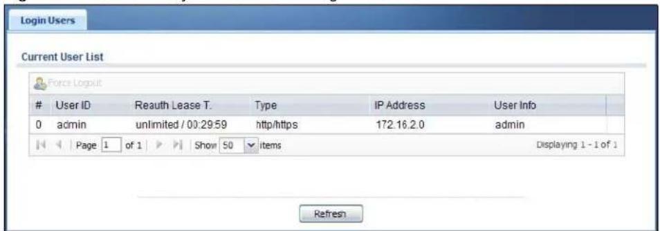
text_image
Login Users Current User List Force LogoutUser ID Reauth Lease T. Type IP Address User Info
0 admin unlimited / 00:29:59 http/https 172.16.2.0 admin Page 1 of 1 Show 50 items Displaying 1 - 1 of 1 RefreshThe following table describes the labels in this screen.
Table 27 Monitor > System Status > Login Users
| LABEL DESCRIPTION | |
| Force Logout Select | a user ID and click this icon to end a user's session. |
| # This field is a sequential value and is not associated with any entry. | |
| User ID | This field displays the user name of each user who is currently logged in to the UAG. |
| Reauth Lease T. | This field displays the amount of reauthentication time remaining and the amount of lease time remaining for each user. See Chapter 32 on page 325. |
| Type | This field displays the way the user logged in to the UAG. |
| IP Address | This field displays the IP address of the computer used to log in to the UAG. |
| User Info | This field displays the types of user accounts the UAG uses. If the user type is ext-user (external user), this field will show its external-group information when you move your mouse over it.If the external user matches two external-group objects, both external-group object names will be shown. |
| Force Logout Select | a user ID and click this icon to end a user's session. |
| Refresh Click this button to update the information in the screen. | |
7.9 The UPnP Port Status Screen
Use this screen to look at the NAT port mapping rules that UPnP creates on the UAG. To access this screen, click Monitor > System Status > UPnP Port Status.
Figure 60 Monitor > System Status > UPnP Port Status

text_image
UPnP Port Status Forwarded Port Summary RemoveRemote ... External Port Protocol Internal Port Internal Client Internal Client T... Description
Page 1 of 1 Show 50 items No data to display Delete All RefreshThe following table describes the labels in this screen.
Table 28 Monitor > System Status > UPnP Port Status
| LABEL DESCRIPTION | |
| Remove Select an entry and click this button to remove it from the list. | |
| # This is the index number of the UPnP-created NAT mapping rule entry. | |
| Remote Host | This field displays the source IP address (on the WAN) of inbound IP packets. Since this is often a wildcard, the field may be blank.When the field is blank, the UAG forwards all traffic sent to the External Port on the WAN interface to the Internal Client on the Internal Port.When this field displays an external IP address, the NAT rule has the UAG forward inbound packets to the Internal Client from that IP address only. |
| External Port | This field displays the port number that the UAG “listens” on (on the WAN port) for connection requests destined for the NAT rule’s Internal Port and Internal Client. The UAG forwards incoming packets (from the WAN) with this port number to the Internal Client on the Internal Port (on the LAN). If the field displays “0”, the UAG ignores the Internal Port value and forwards requests on all external port numbers (that are otherwise unmapped) to the Internal Client. |
| Protocol | This field displays the protocol of the NAT mapping rule (TCP or UDP). |
| Internal Port | This field displays the port number on the Internal Client to which the UAG should forward incoming connection requests. |
| Internal Client | This field displays the DNS host name or IP address of a client on the LAN. Multiple NAT clients can use a single port simultaneously if the internal client field is set to 255.255.255.255 for UDP mappings. |
| Internal Client Type | This field displays the type of the client application on the LAN. |
| Description This field displays a text explanation of the NAT mapping rule. | |
| Delete All Click this to remove all mapping rules from the NAT table. | |
| Refresh Click this button to update the information in the screen. | |
7.10 The USB Storage Screen
This screen displays information about a connected USB storage device. Click Monitor > System Status > USB Storage to display this screen.
Figure 61 Monitor > System Status > USB Storage

text_image
Storage Information Information Device Description: Sony MSAC-UAM2 Usage: 2.9GB /3.8GB (76.8 %) File System: FAT32 Speed: USB 2.0 480Mbps Status: Ready Remove Now Detail: DeactivatedThe following table describes the labels in this screen.
Table 29 Monitor > System Status > USB Storage
| LABEL DESCRIPTION | |
| Device description | This is a basic description of the type of USB device. |
| Usage | This field displays how much of the USB storage device's capacity is currently being used out of its total capacity and what percentage that makes. |
| Filesystem This field displays what file system the USB storage device is formatted with. This field displays Unknown if the file system of the USB storage device is not supported by the UAG, such as NTFS. | |
| Speed This field displays the connection speed the USB storage device supports. | |
| Status | Ready - you can have the UAG use the USB storage device.ClickRemove Nowto stop the UAG from using the USB storage device so you can remove it.Unused- the connected USB storage device was manually unmounted by using the Remove Nowbutton or for some reason the UAG cannot mount it.ClickUse Itto have the UAG mount a connected USB storage device. This button is grayed out if the file system is not supported (unknown) by the UAG none- no USB storage device is connected. |
| Detail This field displays any other information the UAG retrieves from the USB storage device.Deactivated- the use of a USB storage device is disabled (turned off) on the UAG.OutofSpace- the available disk space is less than the disk space full threshold (see Section 41.2 on page 395 for how to configure this threshold).Mounting- the UAG is mounting the USB storage device.Removing- the UAG is unmounting the USB storage device. none- the USB device is operating normally or not connected. | |
7.11 The Dynamic Guest Screen
Dynamic guest accounts can be automatically generated for guest users by using a connected statement printer or the web configurator with the guest-manager account (see Section 26.3.1 on page 263 for more information). A dynamic guest account has a dynamically-created user name and password. Guest users can log in with the dynamic guest accounts when connecting to an SSID for a specified time unit. Use this screen to look at a list of dynamic guest user accounts on the UAG's local database. To access this screen, click Monitor > System Status > Dynamic Guest.
Figure 62 Monitor > System Status > Dynamic Guest

text_image
Dynamic Users Dynamic Guest List Remove RefreshStatus Userna... Create Time Remaining Time Pe... Expiration Ti... Charge Payment... Phone N... User Role
1 mx0y33 2013-04-16 ... 00:30:00 00:30:00 2013-04-17 ... TWD 0 cash N/A billing-u... 2 depwtk 2013-04-16 ... 00:30:00 00:30:00 2013-04-17 ... TWD 0 cash N/A billing-u... 3 h9euht 2013-04-16 ... 00:30:00 00:30:00 2013-04-17 ... TWD 0 cash N/A billing-u... Page 1 of 1 Show 50 items Displaying 1 - 3 of 3 RefreshThe following table describes the labels in this screen.
Table 30 Monitor > System Status > Dynamic Guest
| LABEL DESCRIPTION | |
| Remove Select an | entry and click this button to remove it from the list. |
| Note: If you delete a valid user account which is in use, the UAG ends the user session. | |
| Refresh Click this | button to update the information in the screen. |
| # This is the index | number of the dynamic guest account in the list. |
| Status This field displays whether an account expires or not. | |
| Username This field displays the user name of the account. | |
| Create Time This field displays when the account was created. | |
| Remaining Time | This field displays the amount of Internet access time remaining for each account. |
| Time Period This field displays the total account of time the account can use to access the Internet through the UAG. | |
| Expiration Time This field displays the date and time the account becomes invalid. | |
| Note: Once the time allocated to a dynamic account is used up or a dynamic account remains un-used after the expiration time, the account is deleted from the account list. | |
| Charge This field displays the total cost of the account. | |
| Payment Info This field displays the method of payment for each account. | |
| Phone Num This field displays the mobile phone number for the account. | |
| User Role | This field displays the role of the account. |
| Refresh Click this | button to update the information in the screen. |
The following table describes the icons in this screen.
Table 31 Monitor > System Status > Dynamic Guest Icons
| LABEL | DESCRIPTION |
 | This guest account is un-used. |
| [ZBWY] | This guest account is in use and online. |
| [02KB] | This guest account has been used but is offline now. |
 | This guest account expired. |
 | This guest account has been deleted. |
7.12 The AP List Screen
Use this screen to view which APs are currently connected to the UAG. To access this screen, click Monitor > Wireless > AP Information > AP List.
Figure 63 Monitor > Wireless > AP Information > AP List
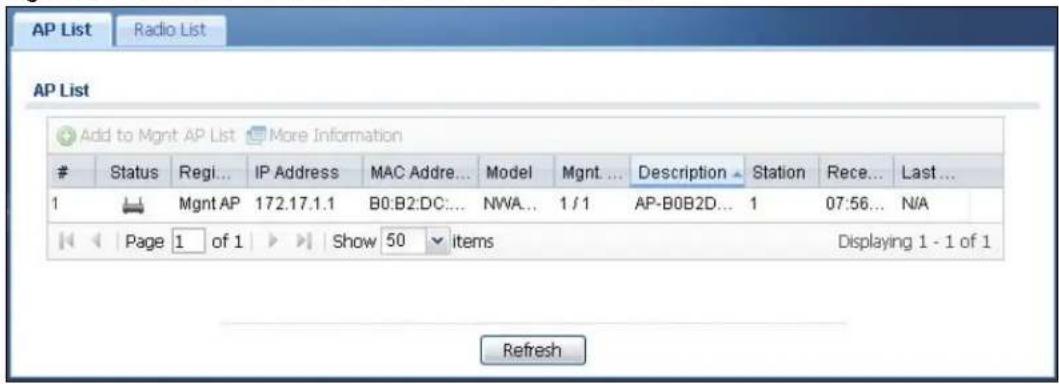
text_image
AP List Radio List AP List Add to Mgmt AP List More InformationStatus Regi... IP Address MAC Addre... Model Mgmt ... Description Station Rece... Last...
1 Mgmt AP 172.17.1.1 B0:B2:DC:... NWA... 1 / 1 AP-B0B2D... 1 07:56... N/A Page 1 of 1 Show 50 items Displaying 1 - 1 of 1 RefreshThe following table describes the labels in this screen.
Table 32 Monitor > Wireless > AP Information > AP List
| LABEL DESCRIPTION | |
| Add to Mgmt AP List | Click this to add the selected AP to the managed AP list. |
| More Information | Click this to view a daily station count about the selected AP. The count records station activity on the AP over a consecutive 24 hour period. |
| # This is the AP's index number in this list. | |
| Status | This visually displays the AP's connection status with icons. For details on the different Status states, see the next table. |
| Registration | This indicates whether the AP is registered with the managed AP list. |
| IP Address This displays the AP's IP address. | |
| MAC Address This displays the AP's MAC address. | |
| Model This displays the AP's model number. | |
| Mgmt. VLAN ID(AC/AP) | This displays the Access Controller (the UAG) management VLAN ID setting for the AP and the runtime management VLAN ID setting on the AP.VLAN Conflict displays if the AP's management VLAN ID does not match the UAG's management VLAN ID setting for the AP. This field displays n/ a if the UAG cannot get VLAN information from the AP. |
| Description | This displays the AP's associated description. The default description is “AP-” + the AP's MAC Address. |
| Station This displays the number of stations (aka wireless clients) associated with the AP. | |
| Recent On-line Time | This displays the most recent time the AP came on-line. N/ A displays if the AP has not come on-line since the UAG last started up. |
| Last Off-line Time | This displays the most recent time the AP went off-line. N/ A displays if the AP has either not come on-line or gone off-line since the UAG last started up. |
The following table describes the icons in this screen.
Table 33 Monitor > Wireless > AP Information > AP List Icons
| LABEL DESCRIPTION | |
| [2AC8] | This AP is not on the management list. |
| [4ZSH] | This AP is on the management list and online. |
| [3CHS] | This AP is in the process of having its firmware updated. |
 | This AP is on the management list but offline. |
| [403S] | This indicates one of the following cases:This AP has a runtime management VLAN ID setting that conflicts with the VLAN ID setting on the Access Controller (the UAG).A setting the UAG assigns to this AP does not match the AP's capability. |
7.12.1 Station Count of AP
Use this screen to look at station statistics for the connected AP. To access this screen, select an entry and click the More Information button in the AP List screen.
Figure 64 Monitor > Wireless > AP Information > AP List > Station Count of AP
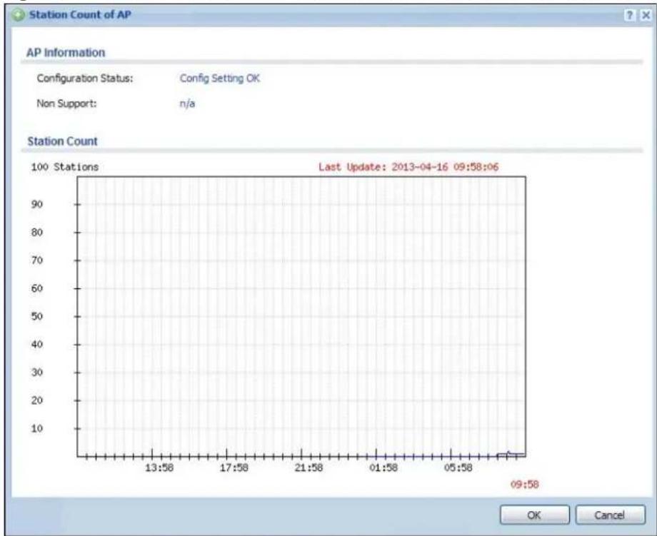
line
| Time | Station Count | | -------- | ------------- | | 13:58 | 0 | | 17:58 | 0 | | 21:58 | 0 | | 01:58 | 0 | | 05:58 | 0 | | 09:58 | 0 |The following table describes the labels in this screen.
Table 34 Monitor > Wireless > AP Information > AP List > Station Count of AP
| LABEL DESCRIPTION | |
| Configuration Status | This displays whether or not any of the AP's configuration is in conflict with the UAG's settings for the AP. |
| Non Support If any | of the AP's configuration conflicts with the UAG's settings for the AP, this field displays which configuration conflicts. It displays n/ a if none of the AP's configuration conflicts with the UAG's settings for the AP. |
| Station Count | |
| The y-axis represents the number of connected stations. | |
| The x-axis shows the time over which a station was connected. | |
| Last Update | This field displays the date and time the information in the window was last updated. |
7.13 The Radio List Screen
Use this screen to view statistics about the wireless radio transmitters in each of the APs connected to the UAG. To access this screen, click Monitor > Wireless > AP Information > Radio List.
Figure 65 Monitor > Wireless > AP Information > Radio List

text_image
AP List Radio List Radio List More InformationAP D... Model MAC ... R... O... Profile Freq... Chan... St... Rx PKT Tx PKT Rx F... Tx R...
1 AP-B... NWA... B0:B... 1 AP default 2.4GHz 6 1 10947 16027 100161 12544 2 AP-B... NWA... B0:B... 2 AP defa... 5GHz 36/40 0 0 3279 330710 4928 Page 1 of 1 Show 50 items Displaying 1 - 2 of 2 RefreshThe following table describes the labels in this screen.
Table 35 Monitor > Wireless > AP Information > Radio List
| LABEL DESCRIPTION | |
| More Information | Click this to view additional information about the selected radio's SSID(s), wireless traffic and wireless clients. Information spans a 24 hour period. |
| # This is the radio's index number in this list. | |
| AP Description | This displays the description of the AP to which the radio belongs. |
| Model This displays the model of the AP to which the radio belongs. | |
| MAC Address This displays the MAC address of the radio. | |
| Radio This indicates the radio number on the AP to which it belongs. | |
| OP Mode | This indicates the radio's operating mode, such as AP (access point). |
| Profile This indicates the profile name to which the radio belongs. | |
| Frequency Band | This indicates the wireless frequency currently being used by the radio.This shows - when the radio is in monitor mode. |
| Channel ID This indicates the radio's channel ID. | |
| Station This displays the number of stations (aka wireless clients) associated with the radio. | |
| Rx PKT This displays the total number of packets received by the radio. | |
| Tx PKT This displays the total number of packets transmitted by the radio. | |
| Rx FCS Error Count | This indicates the number of received packet errors accrued by the radio. |
| Tx Retry Count This indicates the number of times the radio has attempted to re-transmit packets. | |
7.13.1 AP Mode Radio Information
This screen allows you to view detailed information about a selected radio's SSID(s), wireless traffic and wireless clients for the preceding 24 hours. To access this window, select an entry and click the More Information button in the Radio List screen.
Figure 66 Monitor > Wireless > AP Information > Radio List > AP Mode Radio Information
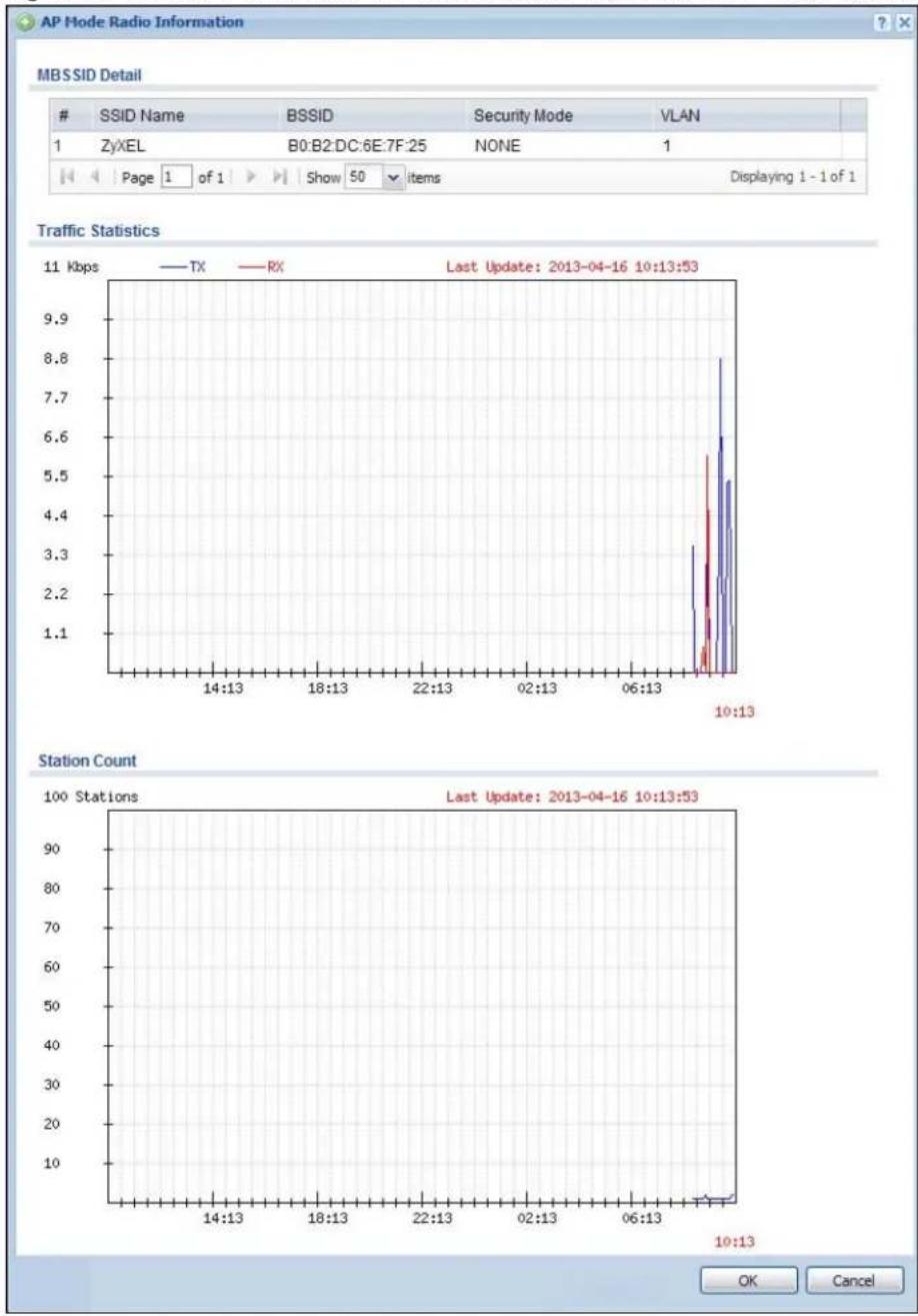
line
| Time | TX | RX | | -------- | ---- | ---- | | 10:13 | 8.8 | 5.5 |The following table describes the labels in this screen.
Table 36 Monitor > Wireless > AP Info > Radio List > AP Mode Radio Information
| LABEL DESCRIPTION | |
| MBSSID Detail | This list shows information about the SSID(s) that is associated with the radio over the preceding 24 hours. |
| # This is the items sequential number in the list. It has no bearing on the actual data in this list. | |
| SSID Name | This displays an SSID associated with this radio. There can be up to eight maximum. |
| BSSID This displays the MAC address associated with the SSID. | |
| Security Mode | This displays the security mode in which the SSID is operating. |
| VLAN This displays the VLAN ID associated with the SSID. | |
| Traffic Statistics | This graph displays the overall traffic information about the radio over the preceding 24 hours. |
| y-axis This axis represents the amount of data moved across this radio in megabytes per second. | |
| x-axis | This axis represents the amount of time over which the data moved across this radio. |
| Station Count | This graph displays information about all the wireless clients that have connected to the radio over the preceding 24 hours. |
| y-axis The y-axis represents the number of connected wireless clients. | |
| x-axis The x-axis shows the time over which a wireless client was connected. | |
| Last Update | This field displays the date and time the information in the window was last updated. |
| OK Click this to close this window. | |
| Cancel Click this to close this window. | |
7.14 The Station List Screen
Use this screen to view statistics pertaining to the associated stations (or "wireless clients"). Click Monitor > Wireless > Station Info to access this screen.
Figure 67 Monitor > Wireless > Station List
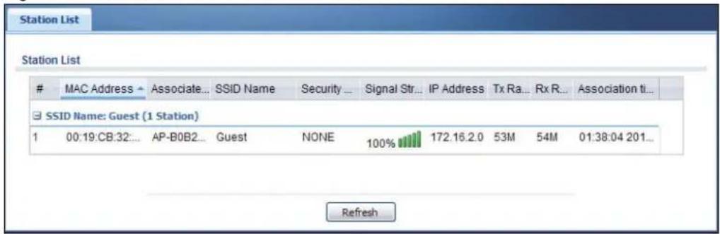
text_image
Station ListMAC Address → Associate... SSID Name Security ... Signal Str... IP Address Tx Ra... Rx R... Association ti...
□ SSID Name: Guest (1 Station) 1 00:19:CB:32... AP-B0B2... Guest NONE 100% 172.16.2.0 53M 54M 01:38:04 201... RefreshThe following table describes the labels in this screen.
Table 37 Monitor > Wireless > Station List
| LABEL DESCRIPTION | |
| SSID Name | This field displays the SSID name with which at least one station is associated.Click + or - to display or hide details about wireless stations that connected to the SSID. |
| # This is the station's index number in this list. | |
| MAC Address This is the station's MAC address. | |
| Associated AP This indicates the AP through which the station is connected to the network. | |
| SSID Name | This indicates the name of the wireless network to which the station is connected. A single AP can have multiple SSIDs or networks. |
| Security Mode This indicates which secure encryption methods is being used by the station to connect to the network. | |
| Signal Strength | This indicates the strength of the signal. The signal strength mainly depends on the antenna output power and the distance between the station and the AP. |
| IP Address | This is the station's IP address. An 169.x.x.x IP address is a private IP address that means the station didn't get the IP address from a DHCP server. |
| Tx Rate This indicates the current data transmission rate of the station. | |
| Rx Rate This indicates the current data receiving rate of the station. | |
| Association Time | This displays the time a wireless station first associated with the AP. |
| Refresh Click this to refresh the items displayed on this page. | |
7.15 The Printer Status Screen
This screen displays information about the connected statement printer, such as SP350E. Click Monitor > Printer Status to display this screen.
Figure 68 Monitor > Printer Status
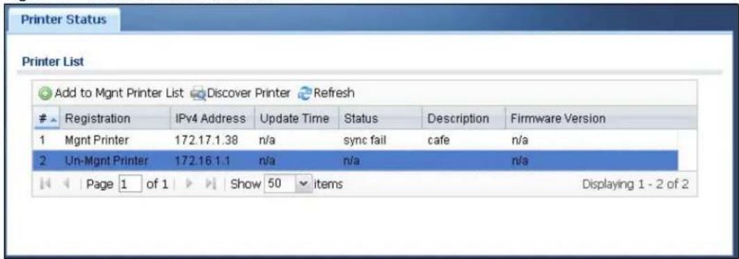
text_image
Printer List Add to Mgmt Printer List Discover Printer RefreshRegistration IPv4 Address Update Time Status Description Firmware Version
1 Mgmt Printer 172.17.1.38 n/a sync fail cafe n/a 2 Uni-Mgmt Printer 172.16.1.1 n/a n/a n/a Page 1 of 1 Show 50 items Displaying 1 - 2 of 2The following table describes the labels in this screen.
Table 38 Monitor > Printer Status
| LABEL DESCRIPTION | |
| Add to Mgmt Printer List | Click this to add the selected AP to the managed printer list. |
| Discover Printer Click this to detect the printer(s) that is connected to the UAG and display the printer information in the list below. | |
| Refresh Click this button to update the information in this screen. | |
| # This is the index number of the printer in the list. | |
| Registration | This field displays whether the printer is added to the managed printer list (Mgmt Printer) or not (Un-Mgmt Printer). |
| IPv4 Address | This field displays the IP address of the printer that you configured in theConfiguration > Printer Managerscreen. |
| Update Time | This field displays the date and time the UAG last synchronized with the printer.This shows n/ a when the printer is not in the managed printer list or the printer status is sync fail. |
| Status | This field displays whether the UAG can connect to the printer and update the printer information.This shows n/ a when the printer is not in the managed printer list. |
| Description This field displays the descriptive name of the printer that you configured in theConfiguration > Printer Managerscreen. | |
| Firmware Version | This field displays the model number and firmware version of the printer.This shows n/ a when the printer is not in the managed printer list or the printer status is sync fail. |
7.16 The VPN 1-1 Mapping Status Screen
This screen displays the status of the active users to which the UAG applied a VPN 1-1 mapping rule.
Click Monitor > VPN 1-1 Mapping to open the following screen.
Figure 69 Monitor > VPN 1-1 Mapping

text_image
VPN 1-1 Mapping Statistics User / VPN 1-1 Mapping Table Force LogoutUser ID ▲ IP Address Mapping IP / Interface Rule Pool
Page 1 of 1 Show 50 items No data to display RefreshThe following table describes the labels in this screen.
Table 39 Monitor > VPN 1-1 Mapping
| LABEL DESCRIPTION | |
| # This field is a sequential value and is not associated with any entry. | |
| User ID | This field displays the user name of each user who is currently logged into the UAG and matches a pre-configured VPN 1-1 mapping rule. |
| IP Address This field | displays the IP address of the computer used to log in to the UAG. |
| Mapping IP/Interface | This field displays the public IP address that the UAG assigns to the user according to the matched VPN 1-1 mapping rule. It also displays the interface through which the outgoing traffic is forwarded. |
| Rule This field displays the index number of the matched VPN 1-1 mapping rule that you configured in the Configuration > VPN 1-1 Mapping screen. | |
| Pool | This field displays the name of the pool profile that you configured for the VPN 1-1 mapping rule. |
| Force Logout Select | a user ID and click this icon to end a user's session. |
| Refresh Click this button to update the information in the screen. | |
7.16.1 VPN 1-1 Mapping Statistics
This screen shows statistics for each of the VPN 1-1 mapping rules. Click Monitor > VPN 1-1 Mapping > Statistics to display this screen.
Figure 70 Monitor > VPN 1-1 Mapping > Statistics
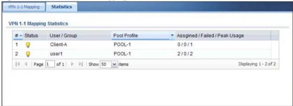
text_image
VPN 1-1 Mapping Statistics VPN 1-1 Mapping StatisticsStatus User / Group Pool Profile Assgined / Failed / Peak Usage
1 Client-A POOL-1 0 / 0 / 1 2 user1 POOL-1 2 / 0 / 2 Page 1 of 1 Show 50 items Displaying 1 - 2 of 2The following table describes the labels in this screen.
Table 40 Monitor > VPN 1-1 Mapping > Statistics
| LABEL DESCRIPTION | |
| # This field displays | the rule's index number in the list. |
| Status The activate | (light bulb) icon is lit when the entry is active and dimmed when the entry is inactive. |
| User/Group | This field displays the name of the user or user group object to which the rule is applied. |
| Pool Profile | This field displays the name of the IP address pool profile to which the rule is applied. |
| Assigned/Failed/Peak Usage | This field displays how many times the UAG applied the rule to a user successfully or failed to apply the rule to a user. This also shows the maximum number of times the UAG has applied the rule to a user successfully. |
7.17 The IPSec Monitor Screen
You can use this screen to display and to manage active IPSec. To access this screen, click Monitor > VPN Monitor > IPSec. The following screen appears. SAs. Click a column's heading cell to sort the table entries by that column's criteria. Click the heading cell again to reverse the sort order.
Figure 71 Monitor > VPN Monitor > IPSec
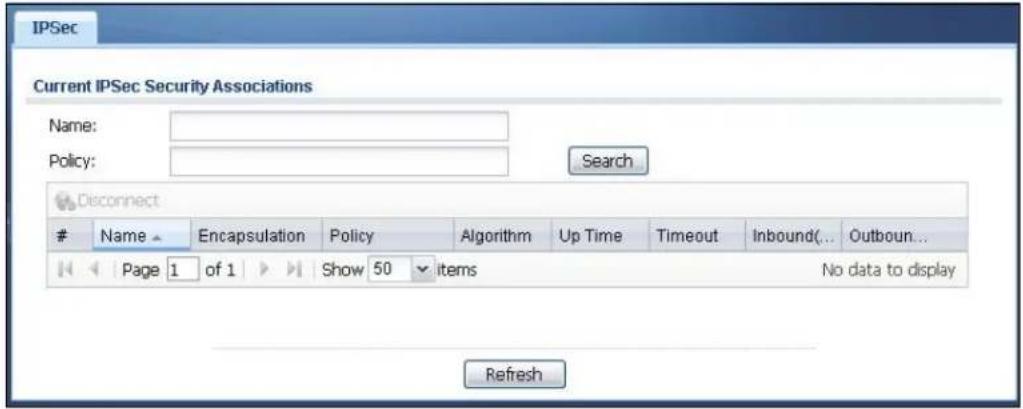
text_image
IPSec Current IPSec Security Associations Name: Policy: Search DisconnectName Encapsulation Policy Algorithm Up Time Timeout Inbound(... Outboun...
Page 1 of 1 Show 50 items No data to display RefreshEach field is described in the following table.
Table 41 Monitor > VPN Monitor > IPSec
| LABEL DESCRIPTION | |
| Name | Enter the name of a IPSec SA here and click Search to find it (if it is associated). You can use a keyword or regular expression. Use up to 30 alphanumeric and _+-.()!^ :?|[]<>/ characters. See Section 7.17.1 on page 104 for more details. |
| Policy | Enter the IP address(es) or names of the local and remote policies for an IPSec SA and click Search to find it. You can use a keyword or regular expression. Use up to 30 alphanumeric and _+-.()!^ :?|{}[]<>/ characters. See Section 7.17.1 on page 104 for more details. |
| Search | Click this button to search for an IPSec SA that matches the information you specified above. |
| Disconnect Select ar | IPSec SA and click this button to disconnect it. |
| Total Connection This field displays the total number of associated IPSec SAs. | |
| Page x of x | This is the number of the page of entries currently displayed and the total number of pages of entries. Type a page number to go to or use the arrows to navigate the pages of entries. |
| Show x items | Select how many entries you want to display on each page. |
| # | This field is a sequential value, and it is not associated with a specific SA. |
| Name This field displays the name of the IPSec SA. | |
| Encapsulation This field displays how the IPSec SA is encapsulated. | |
| Policy | This field displays the content of the local and remote policies for this IPSec SA. The IP addresses, not the address objects, are displayed. |
| Algorithm | This field displays the encryption and authentication algorithms used in the SA. |
| Up Time This field displays how many seconds the IPSec SA has been active. | |
| Timeout | This field displays how many seconds remain in the SA life time, before the UAG automatically disconnects the IPSec SA. |
| Inbound (Bytes) | This field displays the amount of traffic that has gone through the IPSec SA from the remote IPSec router to the UAG since the IPSec SA was established. |
| Outbound (Bytes) | This field displays the amount of traffic that has gone through the IPSec SA from the UAG to the remote IPSec router since the IPSec SA was established. |
| Refresh | Click Refresh to update the information in the display. |
7.17.1 Regular Expressions in Searching IPSec SAs
A question mark (?) lets a single character in the VPN connection or policy name vary. For example, use "a?c" (without the quotation marks) to specify abc, acc and so on.
Wildcards (*) let multiple VPN connection or policy names match the pattern. For example, use “* abc” (without the quotation marks) to specify any VPN connection or policy name that ends with “abc”. A VPN connection named “testabc” would match. There could be any number (of any type) of characters in front of the “abc” at the end and the VPN connection or policy name would still match. A VPN connection or policy name named “testacc” for example would not match.
A * in the middle of a VPN connection or policy name has the UAG check the beginning and end and ignore the middle. For example, with “abc* 123”, any VPN connection or policy name starting with “abc” and ending in “123” matches, no matter how many characters are in between.
The whole VPN connection or policy name has to match if you do not use a question mark or asterisk.
7.18 The Log Screen
Log messages are stored in two separate logs, one for regular log messages and one for debugging messages. In the regular log, you can look at all the log messages by selecting All Logs, or you can select a specific category of log messages (for example, firewall or user). You can also look at the debugging log by selecting Debug Log. All debugging messages have the same priority.
To access this screen, click Monitor > Log. The log is displayed in the following screen.
Note: When a log reaches the maximum number of log messages, new log messages automatically overwrite existing log messages, starting with the oldest existing log message first.
- The maximum possible number of log messages in the UAG varies by model.
Events that generate an alert (as well as a log message) display in red. Regular logs display in black. Click a column's heading cell to sort the table entries by that column's criteria. Click the heading cell again to reverse the sort order.
Figure 72 Monitor > Log
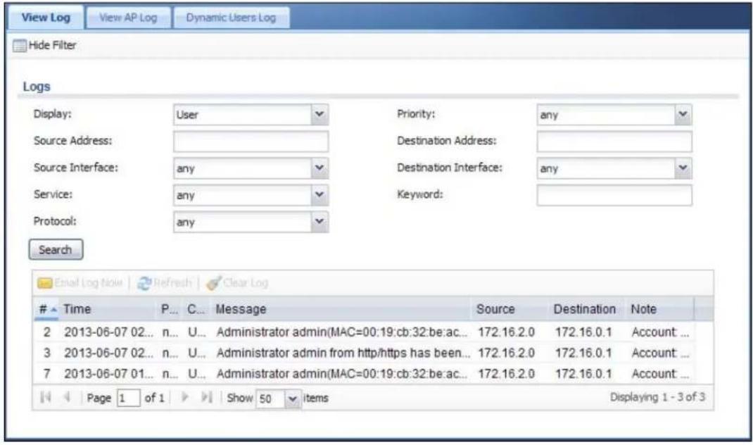
text_image
View Log View AP Log Dynamic Users Log Hide Filter Logs Display: User Priority: any Source Address: Destination Address: Source Interface: any Destination Interface: any Service: any Keyword: Protocol: any Search Email Log Note Refresh Clear LogTime P... C... Message Source Destination Note
2 2013-06-07 02... n... U... Administrator admin(MAC=00:19:cb:32:be:ac... 172.16.2.0 172.16.0.1 Account ... 3 2013-06-07 02... n... U... Administrator admin from http/https has been... 172.16.2.0 172.16.0.1 Account ... 7 2013-06-07 01... n... U... Administrator admin(MAC=00:19:cb:32:be:ac... 172.16.2.0 172.16.0.1 Account ... Page 1 of 1 Show 50 items Displaying 1 - 3 of 3The following table describes the labels in this screen.
Table 42 Monitor > Log
| LABEL DESCRIPTION | |
| Show Filter / Hide Filter | Click this button to show or hide the filter settings.If the filter settings are hidden, the Display, Email Log Now, Refresh, and Clear Log fields are available.If the filter settings are shown, the Display, Priority, Source Address, Destination Address, Source Interface, Destination Interface, Service, Keyword, Protocol and Search fields are available. |
| Display | Select the category of log message(s) you want to view. You can also view All Logs at one time, or you can view the Debug Log. |
| Priority | This displays when you show the filter. Select the priority of log messages to display. The log displays the log messages with this priority or higher. Choices are: any, emerg, alert, crit, error, warn, notice, and info, from highest priority to lowest priority. This field is read-only if the Category is Debug Log. |
| Source Address | This displays when you show the filter. Type the source IP address of the incoming packet that generated the log message. Do not include the port in this filter. |
| Destination Address | This displays when you show the filter. Type the IP address of the destination of the incoming packet when the log message was generated. Do not include the port in this filter. |
| Source Interface | This displays when you show the filter. Select the source interface of the packet that generated the log message. |
| Destination Interface | This displays when you show the filter. Select the destination interface of the packet that generated the log message. |
| Service This displays | when you show the filter. Select the service whose log messages you would like to see. The Web Configurator uses the protocol and destination port number(s) of the service to select which log messages you see. |
| LABEL | DESCRIPTION |
| Keyword | This displays when you show the filter. Type a keyword to look for in the Message, Source, Destination and Note fields. If a match is found in any field, the log message is displayed. You can use up to 63 alphanumeric characters and the underscore, as well as punctuation marks ( )', :,?! +-*/ = # $% @ ; the period, double quotes, and brackets are not allowed. |
| Protocol | This displays when you show the filter. Select a service protocol whose log messages you would like to see. |
| Search | This displays when you show the filter. Click this button to update the log using the current filter settings. |
| Email Log Now | Click this button to send log message(s) to the Active e-mail address(es) specified in the Send Log To field on the Log Settings page (see Section 42.3.2 on page 439). |
| Refresh Click Refresh to update this screen. | |
| Clear Log | Click this button to clear the whole log, regardless of what is currently displayed on the screen. |
| # | This field is a sequential value, and it is not associated with a specific log message. |
| Time | This field displays the time the log message was recorded. |
| Priority | This field displays the priority of the log message. It has the same range of values as the Priority field above. |
| Category | This field displays the log that generated the log message. It is the same value used in the Display and (other) Category fields. |
| Message | This field displays the reason the log message was generated. The text “[count= x]”, where x is a number, appears at the end of the Message field if log consolidation is turned on (see Log Consolidation in Table 205 on page 441). and multiple entries were aggregated to generate into this one. |
| Source | This field displays the source IP address and the port number in the event that generated the log message. |
| Destination | This field displays the destination IP address and the port number of the event that generated the log message. |
| Note | This field displays any additional information about the log message. |
The Web Configurator saves the filter settings if you leave the View Log screen and return to it later.
7.18.1 View AP Log
Use this screen to view the UAG's current wireless AP log messages. Click Monitor > Log > View AP Log to access this screen.
Figure 73 Monitor > Log > View AP Log
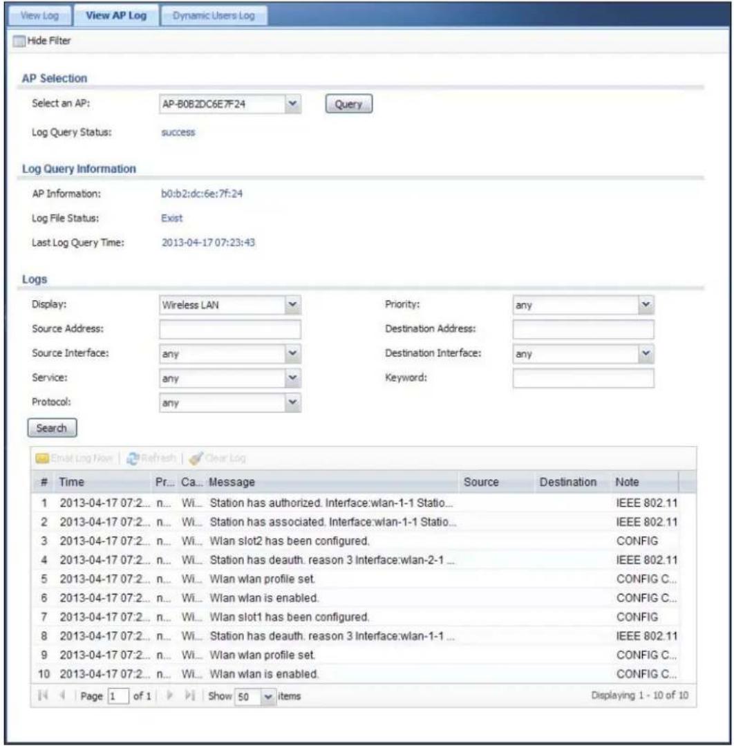
text_image
View Log View AP Log Dynamic Users Log Hide Filter AP Selection Select an AP: AP-B0B2DC6E7F24 Query Log Query Status: success Log Query Information AP Information: b0:b2:dc:6e:7f:24 Log File Status: Exist Last Log Query Time: 2013-04-17 07:23:43 Logs Display: Wireless LAN Priority: any Source Address: Destination Address: Source Interface: any Destination Interface: any Service: any Keyword: Protocol: any SearchTime Pr... Ca... Message Source Destination Note
1 2013-04-17 07:2... n... Wi... Station has authorized. Interface:wlan-1-1 Statio... IEEE 802.11 2 2013-04-17 07:2... n... Wi... Station has associated. Interface:wlan-1-1 Statio... IEEE 802.11 3 2013-04-17 07:2... n... Wi... Wlan slot2 has been configured. CONFIG 4 2013-04-17 07:2... n... Wi... Station has deauth. reason 3 Interface:wlan-2-1 ... IEEE 802.11 5 2013-04-17 07:2... n... Wi... Wlan wlan profile set. CONFIG C... 6 2013-04-17 07:2... n... Wi... Wlan wlan is enabled. CONFIG C... 7 2013-04-17 07:2... n... Wi... Wlan slot1 has been configured. CONFIG 8 2013-04-17 07:2... n... Wi... Station has deauth. reason 3 Interface:wlan-1-1 ... IEEE 802.11 9 2013-04-17 07:2... n... Wi... Wlan wlan profile set. CONFIG C... 10 2013-04-17 07:2... n... Wi... Wlan wlan is enabled. CONFIG C... Page 1 of 1 Show 50 items Displaying 1 - 10 of 10The following table describes the labels in this screen.
Table 43 Monitor > Log > View AP Log
| LABEL DESCRIPTION | |
| Show/ Hide Filter Click this to show or hide the AP log filter. | |
| Select an AP | Select an AP from the list and click Query to view its log messages. |
| LABEL | DESCRIPTION |
| Log Query Status | This indicates the current log query status.init - Indicates the query has not been initialized.querying - Indicates the query is in process.fail - Indicates the query failed.success - Indicates the query succeeded. |
| AP Information This displays the MAC address for the selected AP. | |
| Log File Status This indicates the status of the AP's log messages. | |
| Last Log Query Time | This indicates the last time the AP was queried for its log messages. |
| Display Select the | log file from the specified AP that you want displayed.Note: This criterion only appears when you Show Filter. |
| Priority Select a priority level to use for filtering displayed log messages. | |
| Source Address | Enter a source IP address to display only the log messages that include it.Note: This criterion only appears when you Show Filter. |
| Destination Address | Enter a destination IP address to display only the log messages that include it.Note: This criterion only appears when you Show Filter. |
| Source Interface Enter a source interface to display only the log messages that include it.Note: This criterion only appears when you Show Filter. | |
| Destination Interface | Enter a destination interface to display only the log messages that include it.Note: This criterion only appears when you Show Filter. |
| Service Select a service type to display only the log messages related to it.Note: This criterion only appears when you Show Filter. | |
| Keyword Enter a keyword to display only the log messages that include it.Note: This criterion only appears when you Show Filter. | |
| Protocol Select a protocol to display only the log messages that include it.Note: This criterion only appears when you Show Filter. | |
| Search | Click this to start the log query based on the selected criteria. If no criteria have been selected, then this displays all log messages for the specified AP regardless. |
| Email Log Now | Click this open a new e-mail in your default e-mail program with the selected log attached. |
| Refresh Click this to refresh the log table. | |
| Clear Log Click this to clear the log on the specified AP. | |
| # | This field is a sequential value, and it is not associated with a specific log message. |
| Time | This indicates the time that the log messages was created or recorded on the AP. |
| Priority This indicates the selected log message's priority. | |
| Category | This indicates the selected log message's category. |
| Message | This displays content of the selected log message. |
Table 43 Monitor > Log > View AP Log (continued)
| LABEL DESCRIPTION |
| Source This displays the source IP address of the selected log message. |
| Destination This displays the source IP address of the selected log message. |
| Note This displays any notes associated with the selected log message. |
7.18.2 Dynamic Users Log
Use this screen to view the UAG's dynamic guest account log messages. Click Monitor > Log > Dynamic Users Log to access this screen.
Figure 74 Monitor > Log > Dynamic Users Log
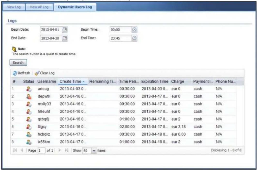
text_image
Views Log View AP Log Dynamic Users Log Logs Begin Date: 2013-04-01 Begin Time: 00:00 End Date: 2013-04-30 End Time: 23:45 Note: The search button is a quest to create time. Search Refresh Clear LogStatus Username Create Time Remaining Ti... Time Peri... Expiration Time Charge Payment I... Phone Nu...
1 arioag 2013-04-03 0... 00:30:00 2013-04-03 0... eur 0 cash N/A 2 depwtk 2013-04-16 0... 00:30:00 2013-04-17 0... eur 0 cash N/A 3 mx0y33 2013-04-16 0... 00:30:00 2013-04-17 0... eur 0 cash N/A 4 h9euht 2013-04-16 0... 00:30:00 2013-04-17 0... eur 0 cash N/A 5 qxbq6j 2013-04-16 0... 01:00:00 2013-04-17 0... eur 2 cash N/A 6 ttigcy 2013-04-16 0... 02:00:00 2013-04-17 0... eur 3,18 cash N/A 7 hcbqkz 2013-04-17 0... 00:30:00 2013-04-18 0... eur 0,00 cash N/A 8 ix55km 2013-04-17 0... 01:00:00 2013-04-18 0... eur 2 cash N/A Page 1 of 1 Show 50 items Displaying 1 - 8 of 8The following table describes the labels in this screen.
Table 44 Monitor > Log > Dynamic Users Log
| LABEL DESCRIPTION | |
| Begin/End Date | Select the first and last dates to specify a time period. The UAG displays log messages only for the accounts created during the specified time period after you click Search. |
| Begin/End Time | Select the begin time of the first date and the end time of the last date to specify a time period. The UAG displays log messages only for the accounts created during the specified time period after you click Search. |
| Search | Click this button to update the information on the screen using the filter criteria in the date and time fields. |
| Refresh Click this | button to update the information in the screen. |
| Clear Log Click this | button to delete the log messages for invalid accounts. |
| # This is the index | number of the dynamic guest account in the list. |
| Status | This field displays whether an account expires or not. |
| Username This field displays the user name of the account. | |
| Create Time This field displays when the account was created. | |
| Remaining Time | This field displays the amount of Internet access time remaining for each account. |
| Time Period This field displays the total account of time the account can use to access the Internet through the UAG. | |
| Expiration Time This field displays the date and time the account becomes invalid.Note: Once the time allocated to a dynamic account is used up or a dynamic account remains un-used after the expiration time, the account is deleted from the account list. | |
| Charge This field displays the total cost of the account. | |
| Payment Info This field displays the method of payment for each account. | |
| Phone Num This field displays the telephone number for the user account. | |
8.1 Overview
Use the Configuration > Licensing > Registration screens to register your UAG and manage its service subscriptions.
8.1.1 What You Can Do in this Chapter
- Use the Registration screen (see Section 8.2 on page 112) to register your UAG with myZyXEL.com.
- Use the Service screen (see Section 8.3 on page 112) to display the status of your service registrations and upgrade licenses.
8.1.2 What you Need to Know
This section introduces the topics covered in this chapter.
myZyXEL.com
myZyXEL.com is ZyXEL's online services center where you can register your UAG and manage subscription services available for the UAG. To use a subscription service, you have to register the UAG and activate the corresponding service at myZyXEL.com (through the UAG).
Note: You need to create a myZyXEL.com account before you can register your device and activate the services at myZyXEL.com.
Go to http://portal.myZyXEL.com with the UAG's serial number and LAN MAC address to register it. Refer to the web site's on-line help for details.
Note: To activate a service on a UAG, you need to access myZyXEL.com via that UAG.
Subscription Services Available on the UAG
At the time of writing, the UAG can use the upgrade service to extend the maximum number of the supported managed APs and the LAN/WLAN users that can connect to the UAG at one time.
Maximum Number of Managed APs
The UAG is initially configured to support up to 8 remote managed APs (such as the NWA5123-NI). You can increase this by subscribing to additional licenses. As of this writing, each license upgrade allows an additional 8 remote managed APs while the maximum number of remote managed APs a single UAG can support is 32.
8.2 Registration Screen
Click the link in this screen to register your UAG with myZyXEL.com. The UAG should already have Internet access before you can register it. Click Configuration > Licensing > Registration in the navigation panel to open the screen as shown next.
Figure 75 Configuration > Licensing > Registration
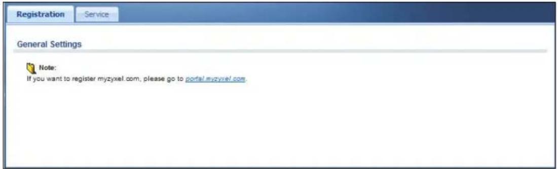
text_image
Registration Service General Settings Note: If you want to register myzyxel.com, please go to portal.myzyxel.com.8.3 Service Screen
Use this screen to display the status of your service registrations. To activate or extend a standard service subscription, purchase an iCard and enter the iCard's PIN number (license key) at myZyXEL.com. Click Configuration > Licensing > Registration > Service to open the screen as shown next.
Figure 76 Configuration > Licensing > Registration > Service
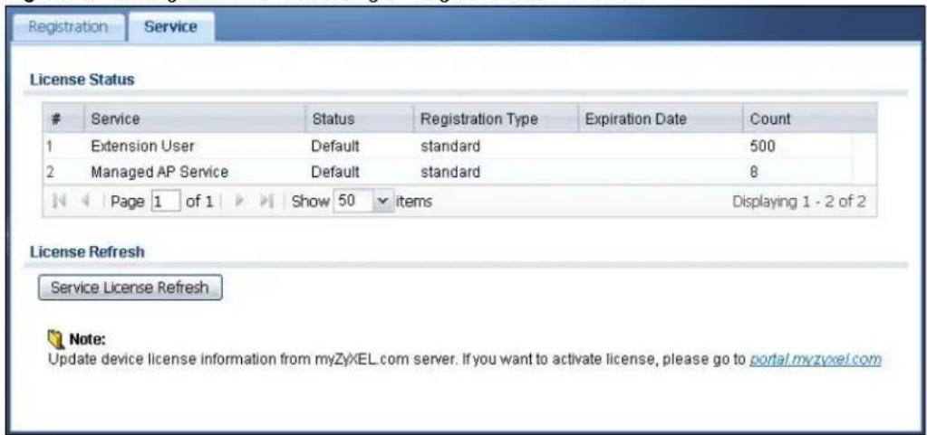
text_image
Registration Service License StatusService Status Registration Type Expiration Date Count
1 Extension User Default standard 500 2 Managed AP Service Default standard 8 Page 1 of 1 Show 50 items Displaying 1 - 2 of 2 License Refresh Service License Refresh Note: Update device license information from myZyXEL.com server. If you want to activate license, please go to portal.myzyxel.comThe following table describes the labels in this screen.
Table 45 Configuration > Licensing > Registration > Service
| LABEL DESCRIPTION | |
| License Status | |
| # This is the entry's position in the list. | |
| Service This lists the services that available on the UAG. | |
| Status | This field displays whether a service is activated (Licensed) or not (Default) or expired (Expired). |
| Registration Type | This field displays whether you applied for a trial application (Trial) or registered a service with your iCard's PIN number (Standard). This field is blank when a service is not activated. |
| Expiration Date This field | displays the date your service expires. |
| Count This field displays | the maximum number of wired and wireless users that may connect to the UAG at the same time or how many managed APs the UAG can support with your current license. |
| Service License Refresh | Click this button to renew service license information (such as the registration status and expiration day). |
9.1 Overview
Use the Wireless screens to configure how the UAG manages the Access Points (APs) that are connected to it.
9.1.1 What You Can Do in this Chapter
- The Controller screen (Section 9.2 on page 114) sets how the UAG allows new APs to connect to the network.
- The AP Management screen (Section 9.3 on page 115) manages all of the APs connected to the UAG.
9.2 Controller Screen
Use this screen to set how the UAG allows new APs to connect to the network. Click Configuration > Wireless > Controller to access this screen.
Figure 77 Configuration > Wireless > Controller

text_image
Configuration Controller Setting Registration Type: Manual Always Accept Apply ResetEach field is described in the following table.
Table 46 Configuration > Wireless > Controller
| LABEL DESCRIPTION | |
| Registration Type | SelectManualto add each AP to the UAG for management, orAlways Acceptto automatically add APs to the UAG for management.Note: Select theManualoption for managing a specific set of APs. This is recommended as the registration mechanism cannot automatically differentiate between friendly and rogue APs.APs must be connected to the UAG by a wired connection or network. |
| Apply Click Applyto save your changes back to the UAG. | |
| Reset | ClickResetto return the screen to its last-saved settings. |
9.3 AP Management Screen
Use this screen to manage all of the APs connected to the UAG. Click Configuration > Wireless > AP Management to access this screen.
Figure 78 Configuration > Wireless > AP Management
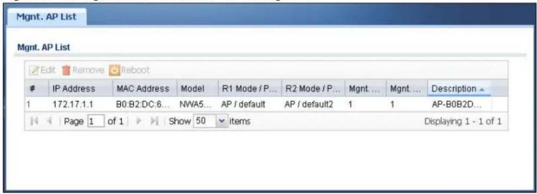
text_image
Mgmt. AP List Edit Remove RebootIP Address MAC Address Model R1 Mode / P... R2 Mode / P... Mgmt... Mgmt... Description ▲
1 172.17.1.1 B0:B2:DC:6... NWA5... AP / default AP / default2 1 1 AP-B0B2D... Page 1 of 1 Show 50 items Displaying 1 - 1 of 1Each field is described in the following table.
Table 47 Configuration > Wireless > AP Management
| LABEL DESCRIPTION | |
| Edit | Select an AP and click this button to edit its properties. |
| Remove | Select an AP and click this button to remove it from the list.Note: If in theConfiguration > Wireless >Controllerscreen you set theRegistration Type toAlways Accept, then as soon as you remove an AP from this list it reconnects. |
| Reboot Select an AP and click this button to force it to restart. | |
| # This field is a sequential value, and it is not associated with any entry. | |
| IP Address This field displays the IP address of the AP. | |
| MAC Address This field displays the MAC address of the AP. | |
| Model | This field displays the AP's hardware model information. It displays N/ A (not applicable) only when the AP disconnects from the UAG and the information is unavailable as a result. |
| R1 Mode / Profile | This field displays the operating mode (AP) and AP profile name for Radio 1. It displays n/ a for the profile for a radio not using an AP profile. |
| R2 Mode / Profile | This field displays the operating mode (AP) and AP profile name for Radio 2. It displays n/ a for the profile for a radio not using an AP profile. |
| Mgmt. VLAN ID(AC) | This displays the Access Controller (the UAG) management VLAN ID setting for the AP. |
| Mgmt. VLAN ID(AP) | This displays the runtime management VLAN ID setting on the AP. VLAN Conflict displays if the AP's management VLAN ID does not match the Mgmt. VLAN ID(AC). This field displays n/ a if the UAG cannot get VLAN information from the AP. |
| Description | This field displays the AP's description, which you can configure by selecting the AP's entry and clicking the Edit button. |
9.3.1 Edit AP List
Select an AP and click the Edit button in the Configuration > Wireless > AP Management table to display this screen.
Figure 79 Configuration > Wireless > AP Management > Edit AP List
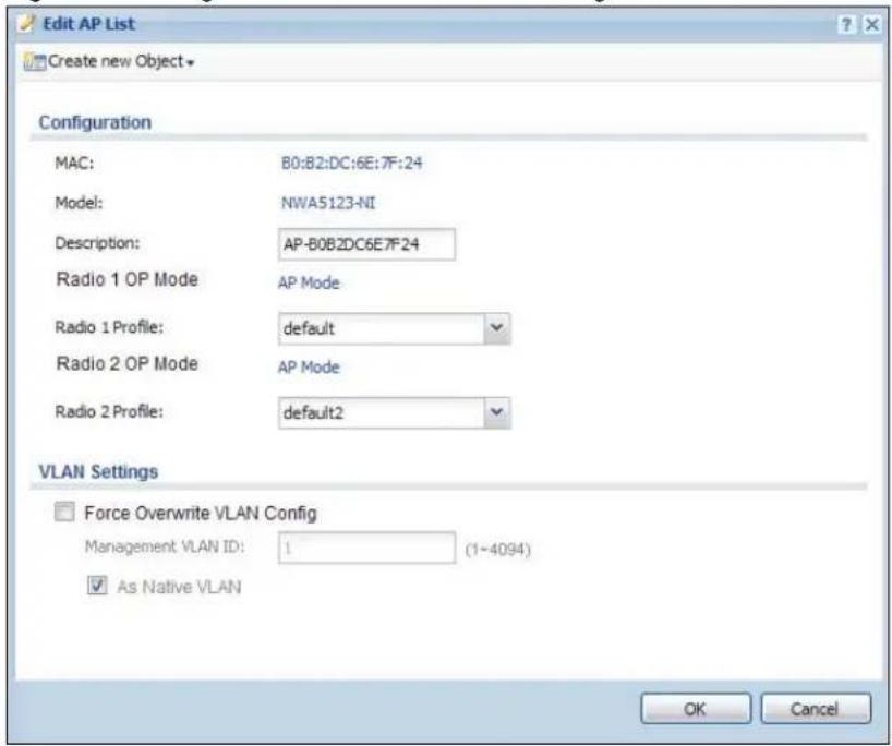
text_image
Edit AP List Create new Object Configuration MAC: B0:B2:DC:6E:7F:24 Model: NWA5123-NI Description: AP-B0B2DC6E7F24 Radio 1 OP Mode AP Mode Radio 1 Profile: default Radio 2 OP Mode AP Mode Radio 2 Profile: default2 VLAN Settings Force Overwrite VLAN Config Management VLAN ID: 1 (1-4094) As Native VLAN OK CancelEach field is described in the following table.
Table 48 Configuration > Wireless > AP Management > Edit AP List
| LABEL DESCRIPTION | |
| Create new Object | Use this menu to create a new Radio Profile object to associate with this AP. |
| MAC This displays the MAC address of the selected AP. | |
| Model | This field displays the AP's hardware model information. It displays N/A (not applicable) only when the AP disconnects from the UAG and the information is unavailable as a result. |
| Description | Enter a description for this AP. You can use up to 31 characters, spaces and underscores allowed. |
| Radio 1/2 OP Mode Select | Select the operating mode for radio 1 or radio 2.AP Mode means the AP can receive connections from wireless clients and pass their data traffic through to the UAG to be managed (or subsequently passed on to an upstream gateway for managing). |
| Radio 1/2 Profile | Select a profile from the list. If no profile exists, you can create a new one through the Create new Object menu. |
| Force Overwrite VLAN Config | Select this to have the UAG change the AP's management VLAN to match the configuration in this screen. |
| Management VLAN ID | Enter a VLAN ID for this AP. |
| As Native VLAN Select | this option to treat this VLAN ID as a VLAN created on the UAG and not one assigned to it from outside the network. |
| OK Click OK to save your changes back to the UAG. | |
| Cancel | Click Cancel to close the window with changes unsaved. |
10.1 Interface Overview
Use the Interface screens to configure the UAG's interfaces. You can also create interfaces on top of other interfaces.
- Ports are the physical ports to which you connect cables.
- Interfaces are used within the system operationally. You use them in configuring various features. An interface also describes a network that is directly connected to the UAG. For example, You connect the LAN network to the LAN interface.
- Zones are groups of interfaces used to ease security policy configuration.
10.1.1 What You Can Do in this Chapter
- Use the Port Grouping screen (Section 10.2 on page 120) to create port groups and to assign physical ports and port groups to Ethernet interfaces.
- Use the Ethernet screens (Section 10.3 on page 122) to configure the Ethernet interfaces. Ethernet interfaces are the foundation for defining other interfaces and network policies.
- Use the PPP screens (Section 10.4 on page 132) for PPPoE or PPTP Internet connections.
- Use the VLAN screens (Section 10.5 on page 138) to divide the physical network into multiple logical networks. VLAN interfaces receive and send tagged frames. The UAG automatically adds or removes the tags as needed. Each VLAN can only be associated with one Ethernet interface.
- Use the Bridge screens (Section 10.6 on page 145) to combine two or more network segments into a single network.
- Use the Virtual Interface screen (Section 10.7.1 on page 153) to create virtual interfaces on top of Ethernet interfaces to tell the UAG where to route packets. You can create virtual Ethernet interfaces, virtual VLAN interfaces, and virtual bridge interfaces.
- Use the Trunk screens (Chapter 11 on page 158) to configure load balancing.
10.1.2 What You Need to Know
Interface Characteristics
Interfaces generally have the following characteristics (although not all characteristics apply to each type of interface).
- An interface is a logical entity through which (layer-3) packets pass.
- An interface is bound to a physical port or another interface.
- Many interfaces can share the same physical port.
- An interface belongs to at most one zone.
- Many interfaces can belong to the same zone.
- Layer-3 virtualization (IP alias, for example) is a kind of interface.
Types of Interfaces
You can create several types of interfaces in the UAG.
- Setting interfaces to the same port role forms a port group. Port groups create a hardware connection between physical ports at the layer-2 (data link, MAC address) level. Port groups are created when you use the Interface > Port Grouping screen to set multiple physical ports to be part of the same interface.
- Ethernet interfaces are the foundation for defining other interfaces and network policies.
- VLAN interfaces receive and send tagged frames. The UAG automatically adds or removes the tags as needed. Each VLAN can only be associated with one Ethernet interface.
- Bridge interfaces create a software connection between Ethernet or VLAN interfaces at the layer-2 (data link, MAC address) level. Unlike port groups, bridge interfaces can take advantage of some security features in the UAG. You can also assign an IP address and subnet mask to the bridge.
- PPP interfaces support Point-to-Point Protocols (PPP). ISP accounts are required for PPPoE/PPTP interfaces.
- Virtual interfaces provide additional routing information in the UAG. There are three types: virtual Ethernet interfaces, virtual VLAN interfaces, and virtual bridge interfaces.
- Trunk interfaces manage load balancing between interfaces.
Port groups and trunks have a lot of characteristics that are specific to each type of interface. See Section 10.3 on page 122 and Chapter 11 on page 158 for details. The other types of interfaces--Ethernet, PPP, VLAN, bridge, and virtual--have a lot of similar characteristics. These characteristics are listed in the following table and discussed in more detail below.
Table 49 Ethernet, PPP, VLAN, Bridge, and Virtual Interface Characteristics
| CHARACTERISTICS | ETHERNET | ETHERNET | PPP | VLAN | BRIDGE | VIRTUAL |
| Name* | wan1, wan2 | lan1, lan2 | pppx | vlanx | brx | ** |
| Configurable Zone | Yes | Yes | Yes | Yes | Yes | No |
| IP Address Assignment | ||||||
| Static IP address | Yes | Yes | Yes | Yes | Yes | Yes |
| DHCP client | Yes | No | Yes | Yes | Yes | No |
| Routing metric | Yes | Yes | Yes | Yes | Yes | Yes |
| Interface Parameters | ||||||
| Bandwidth restrictions | Yes | Yes | Yes | Yes | Yes | Yes |
| Packet size (MTU) | Yes | Yes | Yes | Yes | Yes | No |
| DHCP | ||||||
| DHCP server | No | Yes | No | Yes | Yes | No |
| DHCP relay | No | Yes | No | Yes | Yes | No |
| Connectivity Check | Yes | No | Yes | Yes | Yes | No |
- * The format of interface names other than the Ethernet and ppp interface names is strict. Each name consists of 2-4 letters (interface type), followed by a number (x). For most interfaces, x is limited by the maximum number of the type of interface. For VLAN interfaces, x is defined by the number you enter in the VLAN name field. For example, Ethernet interface names are wan1, lan1, lan2; VLAN interfaces are vlan0, vlan1, vlan2...; and so on.
** - The names of virtual interfaces are derived from the interfaces on which they are created. For example, virtual interfaces created on Ethernet interface wan1 are called wan1:1, wan1:2, and so on. Virtual interfaces created on VLAN interface vlan2 are called vlan2:1, vlan2:2, and so on. You cannot specify the number after the colon(:) in the
Web Configurator; it is a sequential number. You can specify the number after the colon if you use the CLI to set up a virtual interface.
Relationships Between Interfaces
In the UAG, interfaces are usually created on top of other interfaces. Only Ethernet interfaces are created directly on top of the physical ports or port groups. The relationships between interfaces are explained in the following table.
Table 50 Relationships Between Different Types of Interfaces
| INTERFACE REQUIRED PORT / INTERFACE | |
| port group physical port | |
| Ethernet interface physical port | port group |
| VLAN interface Ethernet interface | |
| bridge interface Ethernet interface* | VLAN interface* |
| PPP interface Ethernet interface* | VLAN interface*bridge interfaceWAN1 |
| virtual interface(virtual Ethernet interface)(virtual VLAN interface)(virtual bridge interface) | Ethernet interface*VLAN interface*bridge interface |
| trunk Ethernet interface | VLAN interfacebridge interfacePPP interface |
* - You cannot set up a PPP interface, virtual Ethernet interface or virtual VLAN interface if the underlying interface is a member of a bridge. You also cannot add an Ethernet interface or VLAN interface to a bridge if the member interface has a virtual interface or PPP interface on top of it.
Finding Out More
• See Section 10.8 on page 154 for background information on interfaces.
• See Chapter 11 on page 158 to configure load balancing using trunks.
10.2 Port Grouping
This section introduces port groups and then explains the screen for port groups.
10.2.1 Port Grouping Overview
Use port grouping to create port groups and to assign physical ports and port groups to Ethernet interfaces.
Each physical port is assigned to one Ethernet interface. In port grouping, the Ethernet interfaces are called representative interfaces. If you assign more than one physical port to a representative interface, you create a port group. Port groups have the following characteristics:
- There is a layer-2 Ethernet switch between physical ports in the port group. This provides wire-speed throughput but no security.
- It can increase the bandwidth between the port group and other interfaces.
10.2.2 Port Grouping Screen
To access this screen, click Configuration > Network > Interface > Port Grouping. Define the relationship between physical ports, port groups, and Ethernet interfaces in the Port Grouping screen.
Figure 80 Configuration > Network > Interface > Port Grouping

text_image
Port Grouping Ethernet PPP VLAN Bridge Trunk Configuration wan1 wan2 lan1 lan2 dmz Representative Interface 10/100/1000 4 5 Physical Port Apply ResetThe physical Ethernet ports are shown at the bottom and the Ethernet interfaces are shown at the top of the screen. To add a physical port to a representative interface, drag the physical port onto the corresponding representative interface.
Click Apply to save your changes and apply them to the UAG.
Click Reset to change the port groups to their current configuration (last-saved values).
10.3 Ethernet Summary Screen
This screen lists every Ethernet interface and virtual interface created on top of Ethernet interfaces. To access this screen, click Configuration > Network > Interface > Ethernet.
Unlike other types of interfaces, you cannot create new Ethernet interfaces nor can you delete any of them. If an Ethernet interface does not have any physical ports assigned to it (see Section 10.3 on page 122), the Ethernet interface is effectively removed from the UAG, but you can still configure it.
Ethernet interfaces are similar to other types of interfaces in many ways. They have an IP address, subnet mask, and gateway used to make routing decisions. They restrict the amount of bandwidth and packet size. They can provide DHCP services, and they can verify the gateway is available.
Use Ethernet interfaces to control which physical ports exchange routing information with other routers and how much information is exchanged through each one. The more routing information is exchanged, the more efficient the routers should be. However, the routers also generate more network traffic, and some routing protocols require a significant amount of configuration and management.
Figure 81 Configuration > Network > Interface > Ethernet

text_image
Port Grouping Ethernet PPP VLAN Bridge Trunk Configuration Edit Remove Activate Inactivate Create Virtual Interface Object ReferenceStatus Name IP Address Mask
1 wan1 DHCP -- 0.0.0.0 0.0.0.0 2 wan2 DHCP -- 0.0.0.0 0.0.0.0 3 Ian1 STATIC -- 172.16.0.1 255.255.0.0 4 Ian1:1 STATIC -- 192.168.1.33 255.255.255.0 5 Ian2 STATIC -- 172.17.0.1 255.255.0.0 6 dmz STATIC -- 172.18.0.1 255.255.0.0 Page 1 of 1 Show 50 items Displaying 1 - 6 of 6 Apply ResetEach field is described in the following table.
Table 51 Configuration > Network > Interface > Ethernet
| LABEL DESCRIPTION | |
| Edit | Double-click an entry or select it and click Edit to open a screen where you can modify the entry's settings. |
| Remove | To remove a virtual interface, select it and click Remove. The UAG confirms you want to remove it before doing so. |
| Activate | To turn on an interface, select it and click Activate. |
| Inactivate | To turn off an interface, select it and click Inactivate. |
| Create Virtual Interface | To open the screen where you can create a virtual Ethernet interface, select an Ethernet interface and click Create Virtual Interface. |
| LABEL DESCRIPTION | |
| Object Reference | Select an entry and click Object Reference to open a screen that shows which settings use the entry. See Section 10.3.2 on page 129 for an example. |
| # This field is a sequential value, and it is not associated with any interface. | |
| Status This icon is lit | when the entry is active and dimmed when the entry is inactive. |
| Name This field displays the name of the interface. | |
| IP Address This field displays the current IP address of the interface. If the IP address is 0.0.0.0 (in the IPv4 network), the interface does not have an IP address yet.In the IPv4 network, this screen also shows whether the IP address is a static IP address (STATIC) or dynamically assigned (DHCP). IP addresses are always static in virtual interfaces. | |
| Mask This field displays the interface's subnet mask in dot decimal notation. | |
| Apply Click Apply to save your changes back to the UAG. | |
| Reset | Click Reset to return the screen to its last-saved settings. |
10.3.1 Ethernet Edit
The Ethernet Edit screen lets you configure IP address assignment, interface parameters, DHCP settings, connectivity check, and MAC address settings. To access this screen, select an entry in the Ethernet summary screen and click the Edit icon. (See Section 10.3 on page 122.)
Note: If you create IP address objects based on an interface's IP address, subnet, or gateway, the UAG automatically updates every rule or setting that uses the object whenever the interface's IP address settings change. For example, if you change the LAN's IP address, the UAG automatically updates the corresponding interface-based, LAN subnet address object.
Figure 82 Configuration > Network > Interface > Ethernet > Edit (External Type)
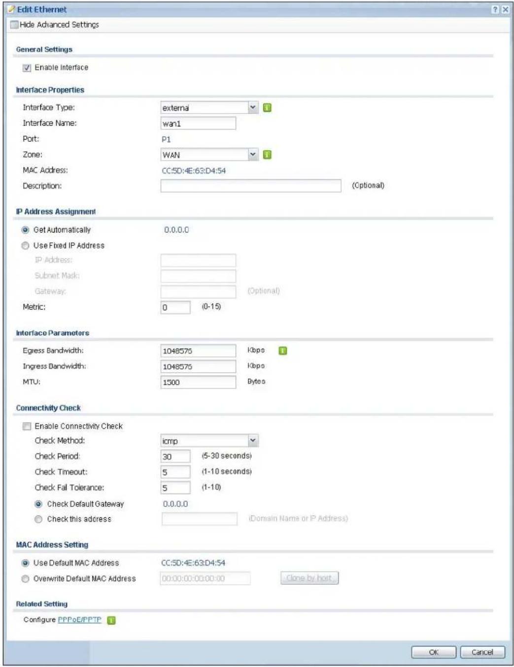
text_image
Edit Ethernet Hide Advanced Settings General Settings Enable Interface Interface Properties Interface Type: external Interface Name: wan1 Port: P1 Zone: WAN MAC Address: CC:SD:4E:63:D4:54 Description: (Optional) IP Address Assignment Get Automatically 0.0.0.0 Use Fixed IP Address IP Address: Subnet Mask: Gateway: (Optonal) Metric: 0 (0-15) Interface Parameters Egress Bandwidth: 1048575 Kbps Ingress Bandwidth: 1048575 Kbps MTU: 1500 Bytes Connectivity Check Enable Connectivity Check Check Method: icmp Check Period: 30 (5-30 seconds) Check Timeout: 5 (1-10 seconds) Check Fall Tolerance: 5 (1-10) Check Default Gateway 0.0.0.0 Check this address (Domain Name or IP Address) MAC Address Setting Use Default MAC Address CC:SD:4E:63:D4:54 Overwrite Default MAC Address 00:00:00:00:00:00 Clone by host Related Setting Configure PPPoE/PPTP OK CancelFigure 83 Configuration > Network > Interface > Ethernet > Edit (Internal Type)

text_image
Edit Ethernet Hide Advanced Settings General Settings Enable Interface Interface Properties Interface Type: internal Interface Name: lan1 Port: P3 Zone: LAN1 MAC Address: CC:5D:4E:63:D4:56 Description: (Optional) IP Address Assignment IP Address: 172.16.0.1 Subnet Mask: 255.255.0.0 Interface Parameters Egress Bandwidth: 1048575 Kbps Ingress Bandwidth: 1048575 Kbps MTU: 1500 Bytes DHCP Setting DHCP: DHCP Server IP Pool Start Address (Optional): 172.16.1.1 Pool Size: 4096 First DNS Server (Optional): Device Second DNS Server (Optional): Custom Defined Third DNS Server (Optional): Custom Defined First WINS Server (Optional): Second WINS Server (Optional): Default Router (Optional): lan1 IP Lease Time: infinite 1 days 0 hours (Optional) 0 minutes (Optional) Extended Options Add Edit RemoveName Code Type Value
Page 1 of 1 Show 50 items No data to display Enable IP/MAC Binding Enable Logs for IP/MAC Binding Violation Static DHCP Table Add Edit RemoveIP Address MAC Description
Page 1 of 1 Show 50 items No data to display OK CancelThis screen's fields are described in the table below.
Table 52 Configuration > Network > Interface > Ethernet > Edit
| LABEL DESCRIPTION | |
| Show Advanced Settings / Hide Advanced Settings | Click this button to display a greater or lesser number of configuration fields. |
| General Settings | |
| Enable Interface | Select this to enable this interface. Clear this to disable this interface. |
| Interface Properties | |
| Interface Type | Select to which type of network you will connect this interface. When you selectinternalor externalthe rest of the screen's options automatically adjust to correspond. The UAG automatically adds default route and SNAT settings for traffic it routes from internal interfaces to external interfaces; for example LAN to WAN traffic.internalis for connecting to a local network. Other corresponding configuration options: DHCP server and DHCP relay. The UAG automatically adds default SNAT settings for traffic flowing from this interface to an external interface.externalis for connecting to an external network (like the Internet). The UAG automatically adds this interface to the default WAN trunk.Forgeneral, the rest of the screen's options do not automatically adjust and you must manually configure a policy route to add routing and SNAT settings for the interface. |
| Interface Name | Specify a name for the interface. It can use alphanumeric characters, hyphens, and underscores, and it can be up to 11 characters long. |
| Port This is the name of the Ethernet interface's physical port. | |
| Zone | Select the zone to which this interface is to belong. You use zones to apply security settings such as firewall, and remote management. |
| MAC Address | This field is read-only. This is the MAC address that the Ethernet interface uses. |
| Description | Enter a description of this interface. It is not used elsewhere. You can use alphanumeric and () +/ :=?! *#@_-%- characters, and it can be up to 60 characters long. |
| IP Address Assignment | These IP address fields configure an IPv4 IP address on the interface itself. If you change this IP address on the interface, you may also need to change a related address object for the network connected to the interface. For example, if you use this screen to change the IP address of your LAN interface, you should also change the corresponding LAN subnet address object. |
| Get Automatically | This option appears whenInterface Typeis externalorgeneral. Select this to make the interface a DHCP client and automatically get the IP address, subnet mask, and gateway address from a DHCP server. |
| Use Fixed IP Address | This option appears whenInterface Typeis externalorgeneral. Select this if you want to specify the IP address, subnet mask, and gateway manually. |
| IP Address Enterthe IP address for this interface. | |
| Subnet Mask | Enter the subnet mask of this interface in dot decimal notation. The subnet mask indicates what part of the IP address is the same for all computers in the network. |
| Gateway | This option appears whenInterface Typeis externalorgeneral. Enter the IP address of the gateway. The UAG sends packets to the gateway when it does not know how to route the packet to its destination. The gateway should be on the same network as the interface. |
| Metric | This option appears whenInterface Typeis externalorgeneral. Enter the priority of the gateway (if any) on this interface. The UAG decides which gateway to use based on this priority. The lower the number, the higher the priority. If two or more gateways have the same priority, the UAG uses the one that was configured first. |
| Interface Parameters | |
| Egress Bandwidth | Enter the maximum amount of traffic, in kilobits per second, the UAG can send through the interface to the network. Allowed values are 0 - 1048576. |
| Ingress Bandwidth | This is reserved for future use.Enter the maximum amount of traffic, in kilobits per second, the UAG can receive from the network through the interface. Allowed values are 0 - 1048576. |
| MTU Maximum Transmission Unit. Type the maximum size of each data packet, in bytes, that can move through this interface. If a larger packet arrives, the UAG divides it into smaller fragments. Allowed values are 576 - 1500. Usually, this value is 1500. | |
| Connectivity Check | These fields appear when Interface Type is external or general.The interface can regularly check the connection to the gateway you specified to make sure it is still available. You specify how often the interface checks the connection, how long to wait for a response before the attempt is a failure, and how many consecutive failures are required before the UAG stops routing to the gateway. The UAG resumes routing to the gateway the first time the gateway passes the connectivity check. |
| Enable Connectivity Check | Select this to turn on the connection check. |
| Check Method Select the method that the gateway allows.Select icmp to have the UAG regularly ping the gateway you specify to make sure it is still available.Select tcp to have the UAG regularly perform a TCP handshake with the gateway you specify to make sure it is still available. | |
| Check Period Enter the number of seconds between connection check attempts. | |
| Check Timeout | Enter the number of seconds to wait for a response before the attempt is a failure. |
| Check Fail Tolerance | Enter the number of consecutive failures before the UAG stops routing through the gateway. |
| Check Default Gateway | Select this to use the default gateway for the connectivity check. |
| Check this address | Select this to specify a domain name or IP address for the connectivity check. Enter that domain name or IP address in the field next to it. |
| Check Port | This field only displays when you set the Check Method to tcp. Specify the port number to use for a TCP connectivity check. |
| DHCP Setting | This section appears when Interface Type is internal. |
| DHCP Select what type of DHCP service the UAG provides to the network. Choices are:None - the UAG does not provide any DHCP services. There is already a DHCP server on the network.DHCP Relay - the UAG routes DHCP requests to one or more DHCP servers you specify. The DHCP server(s) may be on another network.DHCP Server - the UAG assigns IP addresses and provides subnet mask, gateway, and DNS server information to the network. The UAG is the DHCP server for the network. | |
| These fields appear if the UAG is a DHCP Relay. | |
| Relay Server 1 Enter the IP address of a DHCP server for the network. | |
| Relay Server 2 | This field is optional. Enter the IP address of another DHCP server for the network. |
| These fields appear if the UAG is a DHCP Server. | |
| IP Pool Start Address | Enter the IP address from which the UAG begins allocating IP addresses. If you want to assign a static IP address to a specific computer, use the Static DHCP Table.If this field is blank, the Pool Size must also be blank. In this case, the UAG can assign every IP address allowed by the interface's IP address and subnet mask, except for the first address (network address), last address (broadcast address) and the interface's IP address. |
| Pool Size | Enter the number of IP addresses to allocate. This number must be at least one and is limited by the interface's Subnet Mask. For example, if the Subnet Mask is 255.255.255.0 and IP Pool Start Address is 10.10.10.10, the UAG can allocate 10.10.10.10 to 10.10.10.254, or 245 IP addresses.If this field is blank, the IP Pool Start Address must also be blank. In this case, the UAG can assign every IP address allowed by the interface's IP address and subnet mask, except for the first address (network address), last address (broadcast address) and the interface's IP address. |
| First DNS Server, Second DNS Server, Third DNS Server | Specify the IP addresses up to three DNS servers for the DHCP clients to use. Use one of the following ways to specify these IP addresses.Custom Defined - enter a static IP address.From ISP - select the DNS server that another interface received from its DHCP server.Device - the DHCP clients use the IP address of this interface and the UAG works as a DNS relay. |
| First WINS Server, Second WINS Server | Type the IP address of the WINS (Windows Internet Naming Service) server that you want to send to the DHCP clients. The WINS server keeps a mapping table of the computer names on your network and the IP addresses that they are currently using. |
| Default Router | If you set this interface to DHCP Server, you can select to use either the interface's IP address or another IP address as the default router. This default router will become the DHCP clients' default gateway.To use another IP address as the default router, select Custom Defined and enter the IP address. |
| Lease time Specify | how long each computer can use the information (especially the IP address) before it has to request the information again. Choices are:infinite - select this if IP addresses never expire.days, hours, and minutes - select this to enter how long IP addresses are valid. |
| Extended Options | This table is available if you selected DHCP server.Configure this table if you want to send more information to DHCP clients through DHCP packets. |
| Add | Click this to create an entry in this table. See Section 10.3.3 on page 130. |
| Edit Select an entry in this table and click this to modify it. | |
| Remove Select an entry in this table and click this to delete it. | |
| # This field is a sequential value, and it is not associated with any entry. | |
| Name This is the name of the DHCP option. | |
| Code This is the code number of the DHCP option. | |
| Type This is the type of the set value for the DHCP option. | |
| Value This is the value set for the DHCP option. | |
| Enable IP/MAC Binding | Select this option to have this interface enforce links between specific IP addresses and specific MAC addresses. This stops anyone else from manually using a bound IP address on another device connected to this interface. Use this to make use only the intended users get to use specific IP addresses. |
| Enable Logs for IP/MAC Binding Violation | Select this option to have the UAG generate a log if a device connected to this interface attempts to use an IP address that is bound to another device's MAC address. |
| Static DHCP Table | Configure a list of static IP addresses the UAG assigns to computers connected to the interface. Otherwise, the UAG assigns an IP address dynamically using the interface's IP Pool Start Address and Pool Size. |
| Add Click this to create a new entry. | |
| Edit Select an entry and click this to be able to modify it. | |
| Remove Select an entry and click this to delete it. | |
| # This field is a sequential value, and it is not associated with a specific entry. | |
| IP Address | Enter the IP address to assign to a device with this entry's MAC address. |
| MAC Enter the MAC address to which to assign this entry's IP address. | |
| Description | Enter a description to help identify this static DHCP entry. You can use alphanumeric and () +/ :=?!*#@_&- characters, and it can be up to 60 characters long. |
| MAC Address Setting | This section appears when Interface Type is external or general. Have the interface use either the factory assigned default MAC address, a manually specified MAC address, or clone the MAC address of another device or computer. |
| Use Default MAC Address | Select this option to have the interface use the factory assigned default MAC address. By default, the UAG uses the factory assigned MAC address to identify itself. |
| Overwrite Default MAC Address | Select this option to have the interface use a different MAC address. Either enter the MAC address in the fields or click Clone by host and enter the IP address of the device or computer whose MAC you are cloning. Once it is successfully configured, the address will be copied to the configuration file. It will not change unless you change the setting or upload a different configuration file. |
| Related Setting | |
| Configure PPPoE/PPTP | Click PPPoE/ PPTP if this interface's Internet connection uses PPPoE or PPTP. |
| Configure WAN TRUNK | Click WAN TRUNK to go to a screen where you can set this interface to be part of a WAN trunk for load balancing. |
| Configure Policy Route | Click Policy Route to go to the policy route summary screen where you can manually associate traffic with this interface.You must manually configure a policy route to add routing and SNAT settings for an interface with the Interface Type set to general. You can also configure a policy route to override the default routing and SNAT behavior for an interface with an Interface Type of internal or external. |
| OK | Click OK to save your changes back to the UAG. |
| Cancel | Click Cancel to exit this screen without saving. |
10.3.2 Object References
When a configuration screen includes an Object Reference icon, select a configuration object and click Object Reference to open the Object Reference screen. This screen displays which configuration settings reference the selected object. The fields shown vary with the type of object.
Figure 84 Object References

text_image
Object References Object Name lon1Service Priority Name Description
1 Address N/A LAN1_SUBNET N/A 2 Zone_System Default N/A LAN1 N/A Page 1 of 1 Show 50 items Displaying 1 - 2 of 2 Refresh CancelThe following table describes labels that can appear in this screen.
Table 53 Object References
| LABEL DESCRIPTION | |
| Object Name | This identifies the object for which the configuration settings that use it are displayed.Click the object's name to display the object's configuration screen in the main window. |
| # | This field is a sequential value, and it is not associated with any entry. |
| Service | This is the type of setting that references the selected object. Click a service's name to display the service's configuration screen in the main window. |
| Priority | If it is applicable, this field lists the referencing configuration item's position in its list, otherwise N/ A displays. |
| Name | This field identifies the configuration item that references the object. |
| Description If thereferencing configuration item has a description configured, it displays here. | |
| Refresh Click this to update the information in this screen. | |
| Cancel Click Cancel to close the screen. | |
10.3.3 DHCP Extended Options Add/Edit
When you configure an interface as a DHCPv4 server, you can additionally add DHCP extended options which have the UAG to add more information in the DHCP packets. The available fields vary depending on the DHCP option you select in this screen. To open the screen, click Configuration > Network > Interface > Ethernet > Edit, select DHCP Server in the DHCP Setting section, and then click the Add icon or select an entry and click the Edit icon in the Extended Options table.
Figure 85 Configuration > Network > Interface > Ethernet > Edit > Add/Edit Extended Options

text_image
Add DHCP Option Option: User Defined Name: User_Defined Code: Type: BOOLEAN Value:The following table describes labels that can appear in this screen.
Table 54 Configuration > Network > Interface > Ethernet > Edit > Add/Edit Extended Options
| LABEL DESCRIPTION | |
| Option Select which | DHCP option that you want to add in the DHCP packets sent through the interface. See Table 55 for more information. |
| Name | This field displays the name of the selected DHCP option. If you selectedUser Definedin theOptionfield, enter a descriptive name to identify the DHCP option. You can enter up to 16 characters ("a-z", "A-Z, "0-9", "-", and "_") with no spaces allowed. The first character must be alphabetical (a-z, A-Z). |
| Code | This field displays the code number of the selected DHCP option. If you selectedUser Definedin theOptionfield, enter a number for the option. This field is mandatory. |
| Type | This is the type of the selected DHCP option. If you selectedUser Definedin theOptionfield, select an appropriate type for the value that you will enter in the next field. Only advanced users should configureUser Defined. Misconfiguration could result in interface lockout. |
| Value | Enter the value for the selected DHCP option. For example, if you selectedTFTP Server Name(66)and the type is TEXT, enter the DNS domain name of a TFTP server here. If you selected theTime Offset(2)option, the type isBooleanand you have to enter a Boolean value which should be either 0 or 1, where 1 interpreted as true and 0 is interpreted as false.This field is mandatory. |
| First IP Address, Second IP Address, Third IP Address | If you selectedTime Server(4),NTP Server(41),SIP Server(120),CAPWAP AC(138),orTFTP Server(150),you have to enter at least one IP address of the corresponding servers in these fields. The servers should be listed in order of your preference. |
| First Enterprise ID, Second Enterprise ID | If you selectedVIVC(124)orVIVS(125),you have to enter at least one vendor's 32-bit enterprise number in these fields. An enterprise number is a unique number that identifies a company. |
| First Class, Second Class | If you selectedVIVC(124),enter the details of the hardware configuration of the host on which the client is running, or of industry consortium compliance. |
| First Information, Second Information | If you selectedVIVS(125),enter additional information for the corresponding enterprise number in these fields. |
| First FQDN, Second FQDN, Third FQDN | If theTypeis FQDN,you have to enter at least one domain name of the corresponding servers in these fields. The servers should be listed in order of your preference. |
Table 54 Configuration > Network > Interface > Ethernet > Edit > Add/Edit Extended Options
| LABEL | DESCRIPTION |
| OK | Click this to close this screen and update the settings to the previous Edit screen. |
| Cancel Click Cancel | to close the screen. |
The following table lists the available DHCP extended options (defined in RFCs) on the UAG. See RFCs for more information.
Table 55 DHCP Extended Options
| OPTION NAME CODE DESCRIPTION | ||
| Time Offset | 2 | This option specifies the offset of the client's subnet in seconds from Coordinated Universal Time (UTC). |
| Time Server 4 This option specifies a list of Time servers available to the client. | ||
| NTP Server 42 This option specifies a list of the NTP servers available to the client by IP address. | ||
| TFTP Server Name | 66 | This option is used to identify a TFTP server when the “sname” field in the DHCP header has been used for DHCP options. The minimum length of the value is 1. |
| Bootfile 67 This option is used to identify a bootfile when the “file” field in the DHCP header has been used for DHCP options. The minimum length of the value is 1. | ||
| SIP Server | 120 | This option carries either an IPv4 address or a DNS domain name to be used by the SIP client to locate a SIP server. |
| VIVC | 124 | Vendor-Identifying Vendor Class optionA DHCP client may use this option to unambiguously identify the vendor that manufactured the hardware on which the client is running, the software in use, or an industry consortium to which the vendor belongs. |
| VIVS | 125 | Vendor-Identifying Vendor-Specific optionDHCP clients and servers may use this option to exchange vendor-specific information. |
| CAPWAP AC | 138 | CAPWAP Access Controller addresses optionThe Control And Provisioning of Wireless Access Points Protocol allows a Wireless Termination Point (WTP) to use DHCP to discover the Access Controllers to which it is to connect. This option carries a list of IPv4 addresses indicating one or more CAPWAP ACs available to the WTP. |
| TFTP Server | 150 | The option contains one or more IPv4 addresses that the client may use. The current use of this option is for downloading configuration from a VoIP server via TFTP; however, the option may be used for purposes other than contacting a VoIP configuration server. |
10.4 PPP Interfaces
Use PPPoE/PPTP interfaces to connect to your ISP. This way, you do not have to install or manage PPPoE/PPTP software on each computer in the network.
Figure 86 Example: PPPoE/PPTP Interfaces

flowchart
graph LR
    A["3D Block"] <--> B["INTERNET"]
    B <--> C["Server"]
PPPoE/PPTP interfaces are similar to other interfaces in some ways. They have an IP address, subnet mask, and gateway used to make routing decisions; they restrict bandwidth and packet size; and they can verify the gateway is available. There are two main differences between PPPoE/PPTP interfaces and other interfaces.
- You must also configure an ISP account object for the PPPoE/PPTP interface to use.
Each ISP account specifies the protocol (PPPoE or PPTP), as well as your ISP account information. If you change ISPs later, you only have to create a new ISP account, not a new PPPoE/PPTP interface. You should not have to change any network policies.
- You do not set up the subnet mask or gateway.
PPPoE/PPTP interfaces are interfaces between the UAG and only one computer. Therefore, the subnet mask is always 255.255.255.255. In addition, the UAG always treats the ISP as a gateway.
10.4.1 PPP Interface Summary
This screen lists every PPPoE/PPTP interface. To access this screen, click Configuration > Network > Interface > PPP.
Figure 87 Configuration > Network > Interface > PPP
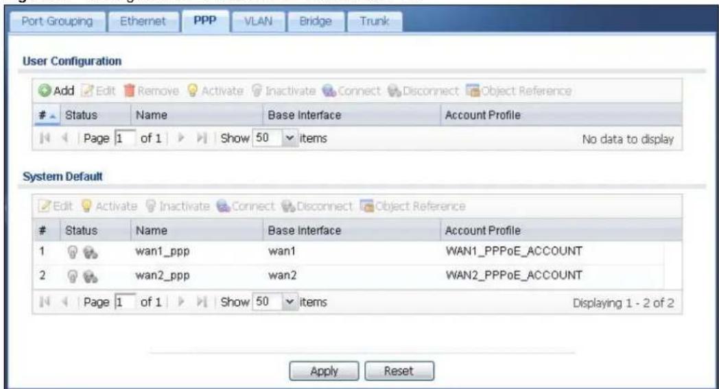
text_image
Port Grouping Ethernet PPP VLAN Bridge Trunk User Configuration Add Edit Remove Activate Inactivate Connect Disconnect Object ReferenceStatus Name Base Interface Account Profile
Page 1 of 1 Show 50 items No data to display System Default Edit Activate Inactivate Connect Disconnect Object ReferenceStatus Name Base Interface Account Profile
1 wan1_ppp wan1 WAN1_PPPoE_ACCOUNT 2 wan2_ppp wan2 WAN2_PPPoE_ACCOUNT Page 1 of 1 Show 50 items Displaying 1 - 2 of 2 Apply ResetEach field is described in the table below.
Table 56 Configuration > Network > Interface > PPP
| LABEL DESCRIPTION | |
| User Configuration / System Default | The UAG comes with the (non-removable) System Default PPP interfaces pre-configured. You can create (and delete) User Configuration PPP interfaces. |
| Add Click this to create | a new user-configured PPP interface. |
| Edit | Double-click an entry or select it and click Edit to open a screen where you can modify the entry's settings. |
| Remove | To remove a user-configured PPP interface, select it and click Remove. The UAG confirms you want to remove it before doing so. |
| Activate | To turn on an entry, select it and click Activate. |
| Inactivate | To turn off an entry, select it and click Inactivate. |
| Connect | To connect an interface, select it and click Connect. You might use this in testing the interface or to manually establish the connection for a Dial-on-Demand PPPoE/PPTP interface. |
| Disconnect | To disconnect an interface, select it and click Disconnect. You might use this in testing the interface. |
| Object Reference | Select an entry and click Object Reference to open a screen that shows which settings use the entry. See Section 10.3.2 on page 129 for an example. |
| # This field is a sequential value, and it is not associated with any interface. | |
| Status | The activate (light bulb) icon is lit when the entry is active and dimmed when the entry is inactive.The connect icon is lit when the interface is connected and dimmed when it is disconnected. |
| Name This field displays the name of the interface. | |
| Base Interface | This field displays the interface on the top of which the PPPoE/PPTP interface is. |
| Account Profile | This field displays the ISP account used by this PPPoE/PPTP interface. |
| Apply | Click Apply to save your changes back to the UAG. |
| Reset | Click Reset to return the screen to its last-saved settings. |
10.4.2 PPP Interface Add/Edit
Note: You have to set up an ISP account before you create a PPPoE/PPTP interface.
This screen lets you configure a PPPoE or PPTP interface. To access this screen, click the Add icon or select an entry in the PPP interface summary screen and click the Edit icon.
Figure 88 Configuration > Network > Interface > PPP > Add
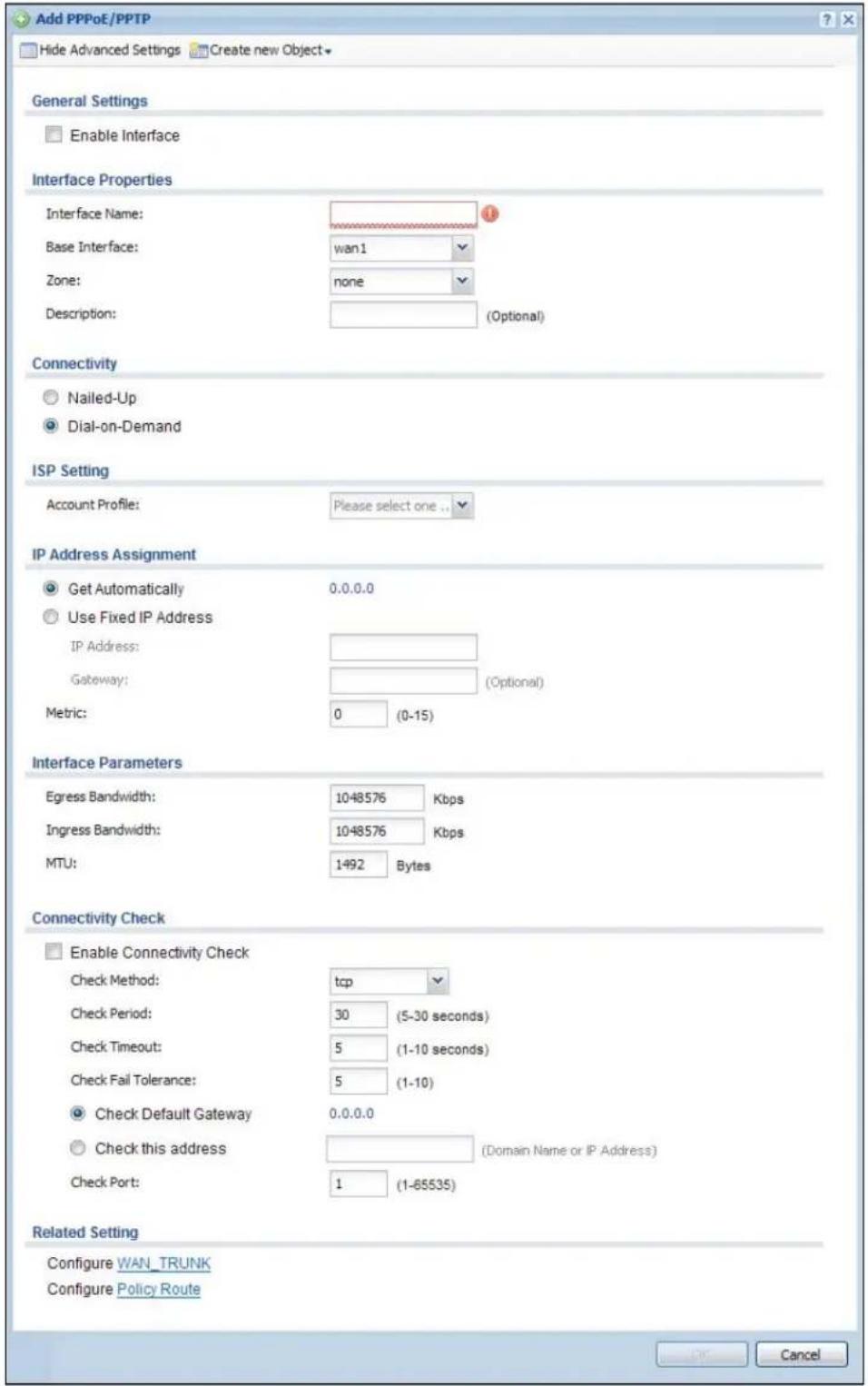
text_image
Add PPPoE/PPTP Hide Advanced Settings Create new Object General Settings Enable Interface Interface Properties Interface Name: Base Interface: wan1 Zone: none Description: (Optional) Connectivity Nailed-Up Dial-on-Demand ISP Setting Account Profile: Please select one... IP Address Assignment Get Automatically 0.0.0.0 Use Fixed IP Address IP Address: Gateway: (Optional) Metric: 0 (0-15) Interface Parameters Egress Bandwidth: 1048576 Kbps Ingress Bandwidth: 1048576 Kbps MTU: 1492 Bytes Connectivity Check Enable Connectivity Check Check Method: tcp Check Period: 30 (5-30 seconds) Check Timeout: 5 (1-10 seconds) Check Fail Tolerance: 5 (1-10) Check Default Gateway 0.0.0.0 Check this address (Domain Name or IP Address) Check Port: 1 (1-65535) Related Setting Configure WAN_TRUNK Configure Policy Route CancelEach field is explained in the following table.
Table 57 Configuration > Network > Interface > PPP > Add/Edit
| LABEL DESCRIPTION | |
| Show Advanced Settings / Hide Advanced Settings | Click this button to display a greater or lesser number of configuration fields. |
| Create new object Click this button to create an ISP Account that you may use for the ISP settings in this screen. | |
| General Settings | |
| Enable Interface | Select this to enable this interface. Clear this to disable this interface. |
| Interface Properties | |
| Interface Name | Specify a name for the interface. It can use alphanumeric characters, hyphens, and underscores, and it can be up to 11 characters long. |
| Base Interface Select the interface upon which this PPP interface is built.Note: Multiple PPP interfaces can use the same base interface. | |
| Zone | Select the zone to which this PPP interface belongs. The zone determines the security settings the UAG uses for the interface. |
| Description | Enter a description of this interface. It is not used elsewhere. You can use alphanumeric and () +/ := ?! * \#@ \ _ \% -$ characters, and it can be up to 60 characters long. |
| Connectivity | |
| Nailed-Up Select this if the PPPoE/PPTP connection should always be up. Clear this to have the UAG establish the PPPoE/PPTP connection only when there is traffic. You might use this option if a lot of traffic needs to go through the interface or it does not cost extra to keep the connection up all the time. | |
| Dial-on-Demand | Select this to have the UAG establish the PPPoE/PPTP connection only when there is traffic. You might use this option if there is little traffic through the interface or if it costs money to keep the connection available. |
| ISP Setting | |
| Account Profile Select the ISP account that this PPPoE/PPTP interface uses. The drop-down box lists ISP accounts by name. Use Create new Object if you need to configure a new ISP account (see Chapter 40 on page 391 for details). | |
| Protocol This field is read-only. It displays the protocol specified in the ISP account. | |
| User Name | This field is read-only. It displays the user name for the ISP account. |
| Service Name | This field is read-only. It displays the PPPoE service name specified in the ISP account. This field is not available if the ISP account uses PPTP. |
| Server IP | This field is read-only. It displays the IP address of the PPTP server specified in the ISP account.This field is not available if the ISP account uses PPPoE. |
| Connection ID | This field is read-only. It displays the identification name for the PPTP server specified in the ISP account.This field is not available if the ISP account uses PPPoE. |
| IP Address Assignment | Click Show Advanced Settings to display more settings. Click Hide Advanced Settings to display fewer settings. |
| Get Automatically | Select this if this interface is a DHCP client. In this case, the DHCP server configures the IP address automatically. The subnet mask and gateway are always defined automatically in PPPoE/PPTP interfaces. |
| Use Fixed IP Address | Select this if you want to specify the IP address manually. |
| LABEL DESCRIPTION | |
| IP Address | This field is enabled if you select Use Fixed IP Address.Enter the IP address for this interface. |
| Gateway | This field is enabled if you select Use Fixed IP Address.Enter the IP address of the gateway. The UAG sends packets to the gateway when it does not know how to route the packet to its destination. The gateway should be on the same network as the interface. |
| Metric | Enter the priority of the gateway (the ISP) on this interface. The UAG decides which gateway to use based on this priority. The lower the number, the higher the priority. If two or more gateways have the same priority, the UAG uses the one that was configured first. |
| Interface Parameters | |
| Egress Bandwidth | Enter the maximum amount of traffic, in kilobits per second, the UAG can send through the interface to the network. Allowed values are 0 - 1048576. |
| Ingress Bandwidth | This is reserved for future use.Enter the maximum amount of traffic, in kilobits per second, the UAG can receive from the network through the interface. Allowed values are 0 - 1048576. |
| MTU Maximum Transmission Unit. Type the maximum size of each data packet, in bytes, that can move through this interface. If a larger packet arrives, the UAG divides it into smaller fragments. Allowed values are 576 - 1492. Usually, this value is 1492. | |
| Connectivity Check | The interface can regularly check the connection to the gateway you specified to make sure it is still available. You specify how often the interface checks the connection, how long to wait for a response before the attempt is a failure, and how many consecutive failures are required before the UAG stops routing to the gateway. The UAG resumes routing to the gateway the first time the gateway passes the connectivity check. |
| Enable Connectivity Check | Select this to turn on the connection check. |
| Check Method Select the method that the gateway allows.Select icmp to have the UAG regularly ping the gateway you specify to make sure it is still available.Select tcp to have the UAG regularly perform a TCP handshake with the gateway you specify to make sure it is still available. | |
| Check Period Enter the number of seconds between connection check attempts. | |
| Check Timeout | Enter the number of seconds to wait for a response before the attempt is a failure. |
| Check Fail Tolerance | Enter the number of consecutive failures before the UAG stops routing through the gateway. |
| Check Default Gateway | Select this to use the default gateway for the connectivity check. |
| Check this address | Select this to specify a domain name or IP address for the connectivity check. Enter that domain name or IP address in the field next to it. |
| Check Port | This field only displays when you set the Check Method to tcp. Specify the port number to use for a TCP connectivity check. |
| Related Setting | |
| Configure WAN_TRUNK | Click WAN_TRUNK to go to a screen where you can configure the interface as part of a WAN trunk for load balancing. |
| Policy Route | Click Policy Route to go to the screen where you can manually configure a policy route to associate traffic with this interface. |
| LABEL DESCRIPTION | |
| OK | Click OK to save your changes back to the UAG. |
| Cancel | Click Cancel to exit this screen without saving. |
10.5 VLAN Interfaces
A Virtual Local Area Network (VLAN) divides a physical network into multiple logical networks. The standard is defined in IEEE 802.1q.
In this example, there are two physical networks and three departments A, B, and C. The physical networks are connected to hubs, and the hubs are connected to the router.
Figure 89 Example: Before VLAN
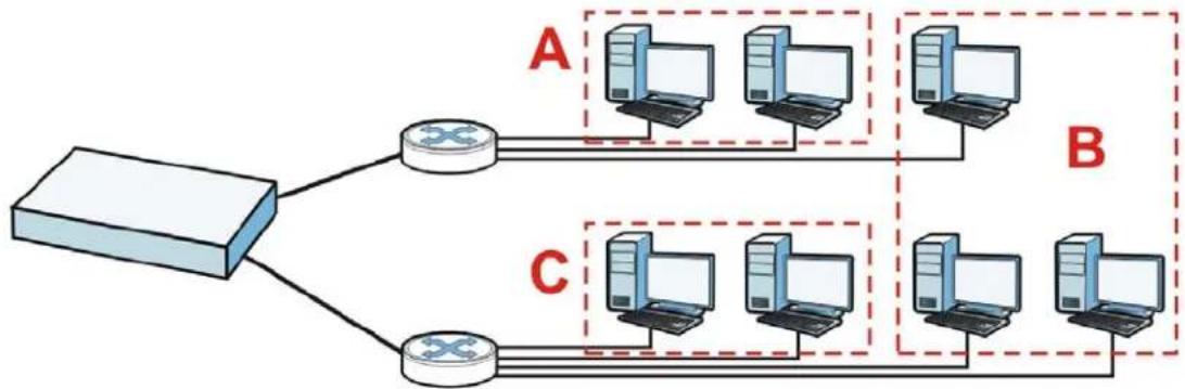
flowchart
graph TD
    A["Router"] --> B["Computer 1"]
    A --> C["Computer 2"]
    B --> D["Computer 3"]
    B --> E["Computer 4"]
    C --> F["Computer 5"]
    C --> G["Computer 6"]
    D --> H["Computer 7"]
    E --> I["Computer 8"]
    F --> J["Computer 9"]
    G --> K["Computer 10"]
    style A fill:#f9f,stroke:#333
    style B fill:#ccf,stroke:#333
    style C fill:#cfc,stroke:#333
    style D fill:#fcc,stroke:#333
    style E fill:#fcc,stroke:#333
    style F fill:#fcc,stroke:#333
    style G fill:#fcc,stroke:#333
    style H fill:#cff,stroke:#333
    style I fill:#cff,stroke:#333
    style J fill:#ffc,stroke:#333
    style K fill:#ffc,stroke:#333
Alternatively, you can divide the physical networks into three VLANs.
Figure 90 Example: After VLAN
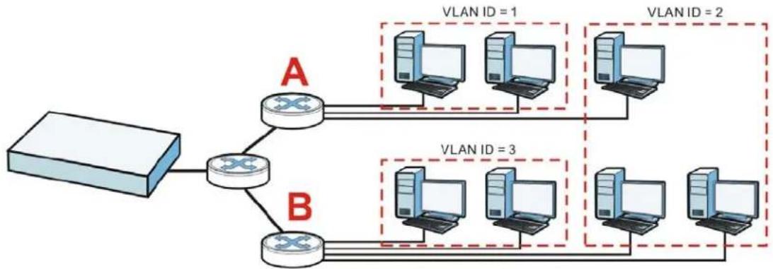
flowchart
graph TD
    A["Router"] --> B["River"]
    B --> C["Switch"]
    C --> D["VLAN ID = 1"]
    C --> E["VLAN ID = 2"]
    B --> F["Switch"]
    F --> G["VLAN ID = 3"]
    F --> H["VLAN ID = 4"]
Each VLAN is a separate network with separate IP addresses, subnet masks, and gateways. Each VLAN also has a unique identification number (ID). The ID is a 12-bit value that is stored in the MAC header. The VLANs are connected to switches, and the switches are connected to the router. (If one switch has enough connections for the entire network, the network does not need switches A and B.)
- Traffic inside each VLAN is layer-2 communication (data link layer, MAC addresses). It is handled by the switches. As a result, the new switch is required to handle traffic inside VLAN 2. Traffic is only broadcast inside each VLAN, not each physical network.
- Traffic between VLANs (or between a VLAN and another type of network) is layer-3 communication (network layer, IP addresses). It is handled by the router.
This approach provides a few advantages.
- Increased performance - In VLAN 2, the extra switch should route traffic inside the sales department faster than the router does. In addition, broadcasts are limited to smaller, more logical groups of users.
- Higher security - If each computer has a separate physical connection to the switch, then broadcast traffic in each VLAN is never sent to computers in another VLAN.
- Better manageability - You can align network policies more appropriately for users. For example, you can set different bandwidth limits for each VLAN (each department in the example above). These rules are also independent of the physical network, so you can change the physical network without changing policies.
In this example, the new switch handles the following types of traffic:
- Inside VLAN 2.
- Between the router and VLAN 1.
- Between the router and VLAN 2.
- Between the router and VLAN 3.
VLAN Interfaces Overview
In the UAG, each VLAN is called a VLAN interface. As a router, the UAG routes traffic between VLAN interfaces, but it does not route traffic within a VLAN interface. All traffic for each VLAN interface can go through only one Ethernet interface, though each Ethernet interface can have one or more VLAN interfaces.
Note: Each VLAN interface is created on top of only one Ethernet interface.
Otherwise, VLAN interfaces are similar to other interfaces in many ways. They have an IP address, subnet mask, and gateway used to make routing decisions. They restrict bandwidth and packet size. They can provide DHCP services, and they can verify the gateway is available.
10.5.1 VLAN Interface Summary Screen
This screen lists every VLAN interface and virtual interface created on top of VLAN interfaces. To access this screen, click Configuration > Network > Interface > VLAN.
Figure 91 Configuration > Network > Interface > VLAN

text_image
Port Role Ethernet PPP VLAN Bridge Trunk Configuration Add Edit Remove Activate Inactivate Create Virtual Interface Object ReferenceStatus Name Port/VID IP Address Mask
1 vlan123 Ian2/123 dhcp -0.0.0.0 0.0.0.0 Page 1 of 1 Show 50 items Displaying 1 - 1 of 1 Apply ResetEach field is explained in the following table.
Table 58 Configuration > Network > Interface > VLAN
| LABEL DESCRIPTION | |
| Add Click this to | create a new VLAN interface. |
| Edit | Double-click an entry or select it and click Edit to open a screen where you can modify the entry's settings. |
| Remove | To remove an entry, select it and click Remove. The UAG confirms you want to remove it before doing so. |
| Activate | To turn on an entry, select it and click Activate. |
| Inactivate | To turn off an entry, select it and click Inactivate. |
| Create Virtual Interface | To open the screen where you can create a virtual interface, select an interface and click Create Virtual Interface. |
| Object References | Select an entry and click Object Reference to open a screen that shows which settings use the entry. See Section 10.3.2 on page 129 for an example. |
| # This field is a sequential value, and it is not associated with any interface. | |
| Status This icon | is lit when the entry is active and dimmed when the entry is inactive. |
| Name This field displays the name of the interface. | |
| Port/VID For VLAN interfaces, this field displaysthe Ethernet interface on which the VLAN interface is createdthe VLAN IDFor virtual interfaces, this field is blank. | |
| IP Address | This field displays the current IP address of the interface. If the IP address is 0.0.0.0, the interface does not have an IP address yet.This screen also shows whether the IP address is a static IP address (static) or dynamically assigned (dhcp). IP addresses are always static in virtual interfaces. |
| Mask This field displays the interface's subnet mask in dot decimal notation. | |
| Apply Click Apply to save your changes back to the UAG. | |
| Reset | Click Reset to return the screen to its last-saved settings. |
10.5.2 VLAN Interface Add/Edit
This screen lets you configure IP address assignment, interface bandwidth parameters, DHCP settings, and connectivity check for each VLAN interface. To access this screen, click the Add icon
or select an entry in the VLAN summary screen and click the Edit icon. The following screen appears.
Figure 92 Configuration > Network > Interface > VLAN > Add

text_image
Add VLAN Hide Advanced Settings General Settings Enable Interface Interface Properties Interface Type: general Interface Name: vlan Zone: none Base Part: van1 VLAN ID: 1-4094 Description: (Optional) IP Address Assignment Use Automatically Use Fixed IP Address IP Address: 0.0.0.0 Subset Mask: 0.0.0.0 Gateway: (Optional) Metric: 0 (0-15) Interface Parameters Express Bandwidth: 10-8576 Kbps Ingress Bandwidth: 10-8576 Kbps MTU: 1500 Bytes Connectivity Check Enable Connectivity Check Check Method: icmp Check Period: 30 (5-30 seconds) Check Timeout: 5 (1-10 seconds) Check Fail Tolerance: 5 (1-10) Check Default Gateway 0.0.0.0 Check this address (Onion Name or IP Address) DHCP Setting DHCP: DHCP Servers IP Pool Start Address (Optional): Pool Size: First DNS Server (Optional): Second DNS Server (Optional): Third DNS Server (Optional): First WINS Server (Optional): Second WINS Server (Optional): Default Router (Optional): vlan IP Lease Time: Infinite days hours (Optional) minutes (Optional) Extended Options Add Name Code Type Value Page 1 of 1 Show 50 Items No data to display Enable IP/MAC Binding Enable Logs for IP/MAC Binding Violation Static DHCP Table Add IP Address - MAC Description Page 1 of 1 Show 50 Items No data to display Related Setting Configure WAN TRUNKS Configure Policy Route CancelEach field is explained in the following table.
Table 59 Configuration > Network > Interface > VLAN > Add/Edit
| LABEL DESCRIPTION | |
| Show Advanced Settings / Hide Advanced Settings | Click this button to display a greater or lesser number of configuration fields. |
| General Settings | |
| Enable Interface | Select this to turn this interface on. Clear this to disable this interface. |
| Interface Properties | |
| Interface Type | Select one of the following option depending on the type of network to which the UAG is connected or if you want to additionally manually configure some related settings.internalis for connecting to a local network. Other corresponding configuration options: DHCP server and DHCP relay. The UAG automatically adds default SNAT settings for traffic flowing from this interface to an external interface.externalis for connecting to an external network (like the Internet). The UAG automatically adds this interface to the default WAN trunk.For general, the rest of the screen's options do not automatically adjust and you must manually configure a policy route to add routing and SNAT settings for the interface. |
| Interface Name | This field is read-only if you are editing an existing VLAN interface. Enter the number of the VLAN interface. You can use a number from 0~4094. For example, vlan0, vlan8, and so on. The total number of VLANs you can configure on the UAG depends on the model. |
| Zone Select the zone to which the VLAN interface belongs. | |
| Base Port | Select the Ethernet interface on which the VLAN interface runs. |
| VLAN ID | Enter the VLAN ID. This 12-bit number uniquely identifies each VLAN. Allowed values are 1 - 4094. (0 and 4095 are reserved.) |
| Description | Enter a description of this interface. It is not used elsewhere. You can use alphanumeric and () +/ :=?! *#@_%- characters, and it can be up to 60 characters long. |
| IP Address Assignment | |
| Get Automatically | Select this if this interface is a DHCP client. In this case, the DHCP server configures the IP address, subnet mask, and gateway automatically. |
| Use Fixed IP Address | Select this if you want to specify the IP address, subnet mask, and gateway manually. |
| IP Address | This field is enabled if you select Use Fixed IP Address.Enter the IP address for this interface. |
| Subnet Mask | This field is enabled if you select Use Fixed IP Address.Enter the subnet mask of this interface in dot decimal notation. The subnet mask indicates what part of the IP address is the same for all computers in the network. |
| Gateway | This field is enabled if you select Use Fixed IP Address.Enter the IP address of the gateway. The UAG sends packets to the gateway when it does not know how to route the packet to its destination. The gateway should be on the same network as the interface. |
| Metric | Enter the priority of the gateway (if any) on this interface. The UAG decides which gateway to use based on this priority. The lower the number, the higher the priority. If two or more gateways have the same priority, the UAG uses the one that was configured first. |
| Interface Parameters | |
| Egress Bandwidth | Enter the maximum amount of traffic, in kilobits per second, the UAG can send through the interface to the network. Allowed values are 0 - 1048576. |
| Ingress Bandwidth | This is reserved for future use.Enter the maximum amount of traffic, in kilobits per second, the UAG can receive from the network through the interface. Allowed values are 0 - 1048576. |
| MTU Maximum Transmission | Transmission Unit. Type the maximum size of each data packet, in bytes, that can move through this interface. If a larger packet arrives, the UAG divides it into smaller fragments. Allowed values are 576 - 1500. Usually, this value is 1500. |
| Connectivity Check The UAG can regularly check the connection to the gateway you specified to make sure it is still available. You specify how often to check the connection, how long to wait for a response before the attempt is a failure, and how many consecutive failures are required before the UAG stops routing to the gateway. The UAG resumes routing to the gateway the first time the gateway passes the connectivity check. | |
| Enable Connectivity Check | Select this to turn on the connection check. |
| Check Method Select the method that the gateway allows.Select icmp to have the UAG regularly ping the gateway you specify to make sure it is still available.Select tcp to have the UAG regularly perform a TCP handshake with the gateway you specify to make sure it is still available. | |
| Check Period Enter the number of seconds between connection check attempts. | |
| Check Timeout | Enter the number of seconds to wait for a response before the attempt is a failure. |
| Check Fail Tolerance | Enter the number of consecutive failures before the UAG stops routing through the gateway. |
| Check Default Gateway | Select this to use the default gateway for the connectivity check. |
| Check this address | Select this to specify a domain name or IP address for the connectivity check. Enter that domain name or IP address in the field next to it. |
| Check Port | This field only displays when you set the Check Method to tcp. Specify the port number to use for a TCP connectivity check. |
| DHCP Setting | The DHCP settings are available for the LAN interfaces. |
| DHCP Select what type of DHCP service the UAG provides to the network. Choices are:None - the UAG does not provide any DHCP services. There is already a DHCP server on the network.DHCP Relay - the UAG routes DHCP requests to one or more DHCP servers you specify. The DHCP server(s) may be on another network.DHCP Server - the UAG assigns IP addresses and provides subnet mask, gateway, and DNS server information to the network. The UAG is the DHCP server for the network. | |
| These fields appear if the UAG is a DHCP Relay. | |
| Relay Server 1 Enter the IP address of a DHCP server for the network. | |
| Relay Server 2 | This field is optional. Enter the IP address of another DHCP server for the network. |
| These fields appear if the UAG is a DHCP Server. | |
| IP Pool Start Address | Enter the IP address from which the UAG begins allocating IP addresses. If you want to assign a static IP address to a specific computer, click Add Static DHCP.If this field is blank, the Pool Size must also be blank. In this case, the UAG can assign every IP address allowed by the interface's IP address and subnet mask, except for the first address (network address), last address (broadcast address) and the interface's IP address. |
| Pool Size | Enter the number of IP addresses to allocate. This number must be at least one and is limited by the interface's Subnet Mask. For example, if the Subnet Mask is 255.255.255.0 and IP Pool Start Address is 10.10.10.10, the UAG can allocate 10.10.10.10 to 10.10.10.254, or 245 IP addresses.If this field is blank, the IP Pool Start Address must also be blank. In this case, the UAG can assign every IP address allowed by the interface's IP address and subnet mask, except for the first address (network address), last address (broadcast address) and the interface's IP address. |
| First DNS Server Second DNS Server Third DNS Server | Specify the IP addresses up to three DNS servers for the DHCP clients to use. Use one of the following ways to specify these IP addresses.Custom Defined - enter a static IP address.From ISP - select the DNS server that another interface received from its DHCP server.Device - the DHCP clients use the IP address of this interface and the UAG works as a DNS relay. |
| First WINS Server, Second WINS Server | Type the IP address of the WINS (Windows Internet Naming Service) server that you want to send to the DHCP clients. The WINS server keeps a mapping table of the computer names on your network and the IP addresses that they are currently using. |
| Default Router | If you set this interface to DHCP Server, you can select to use either the interface's IP address or another IP address as the default router. This default router will become the DHCP clients' default gateway.To use another IP address as the default router, select Custom Defined and enter the IP address. |
| Lease time Specify | how long each computer can use the information (especially the IP address) before it has to request the information again. Choices are:infinite - select this if IP addresses never expire.days, hours, and minutes - select this to enter how long IP addresses are valid. |
| Extended Options | This table is available if you selected DHCP server.Configure this table if you want to send more information to DHCP clients through DHCP packets. |
| Add | Click this to create an entry in this table. See Section 10.3.3 on page 130. |
| Edit Select an entry in this table and click this to modify it. | |
| Remove Select an entry in this table and click this to delete it. | |
| # This field is a sequential value, and it is not associated with any entry. | |
| Name This is the name of the DHCP option. | |
| Code This is the code number of the DHCP option. | |
| Type This is the type of the set value for the DHCP option. | |
| Value This is the value set for the DHCP option. | |
| Enable IP/MAC Binding | Select this option to have the UAG enforce links between specific IP addresses and specific MAC addresses for this VLAN. This stops anyone else from manually using a bound IP address on another device connected to this interface. Use this to make use only the intended users get to use specific IP addresses. |
| Enable Logs for IP/MAC Binding Violation | Select this option to have the UAG generate a log if a device connected to this VLAN attempts to use an IP address that is bound to another device's MAC address. |
| Static DHCP Table | Configure a list of static IP addresses the UAG assigns to computers connected to the interface. Otherwise, the UAG assigns an IP address dynamically using the interface's IP Pool Start Address and Pool Size. |
| Add Click this to create a new entry. | |
| Edit Select an entry and click this to be able to modify it. | |
| Remove Select an entry and click this to delete it. | |
| # This field is a sequential value, and it is not associated with a specific entry. | |
| IP Address | Enter the IP address to assign to a device with this entry's MAC address. |
| MAC Enter the MAC address to which to assign this entry's IP address. | |
| Description | Enter a description to help identify this static DHCP entry. You can use alphanumeric and () +/ := ? ! * # @ _$ - characters, and it can be up to 60 characters long. |
| Related Setting | |
| Configure WAN_TRUNK | Click WAN_TRUNK to go to a screen where you can set this VLAN to be part of a WAN trunk for load balancing. |
| Configure Policy Route | Click Policy Route to go to the screen where you can manually configure a policy route to associate traffic with this VLAN. |
| OK | Click OK to save your changes back to the UAG. |
| Cancel | Click Cancel to exit this screen without saving. |
10.6 Bridge Interfaces
This section introduces bridges and bridge interfaces and then explains the screens for bridge interfaces.
Bridge Overview
A bridge creates a connection between two or more network segments at the layer-2 (MAC address) level. In the following example, bridge X connects four network segments.
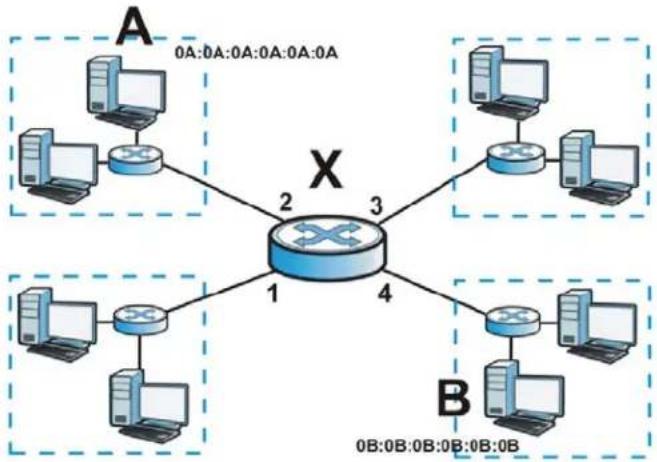
flowchart
graph TD
    A["Switch 1"] -->|0A:0A:0A:0A:0A:0A| A1["Computer"]
    A -->|2| X["Switch 2"]
    A -->|3| X
    A -->|4| B["Switch 3"]
    B -->|0B:0B:0B:0B:0B:0B| B1["Computer"]
    B -->|1| X
    B -->|2| X
    style X fill:#f9f,stroke:#333,stroke-width:2px
When the bridge receives a packet, the bridge records the source MAC address and the port on which it was received in a table. It also looks up the destination MAC address in the table. If the bridge knows on which port the destination MAC address is located, it sends the packet to that port. If the destination MAC address is not in the table, the bridge broadcasts the packet on every port (except the one on which it was received).
In the example above, computer A sends a packet to computer B. Bridge X records the source address 0A:0A:0A:0A:0A:0A and port 2 in the table. It also looks up 0B:0B:0B:0B:0B:0B in the table. There is no entry yet, so the bridge broadcasts the packet on ports 1, 3, and 4.
Table 60 Example: Bridge Table After Computer A Sends a Packet to Computer B
| MAC ADDRESS PORT | |
| 0A:0A:0A:0A:0A:0A 2 |
If computer B responds to computer A, bridge X records the source address 0B:0B:0B:0B:0B:0B and port 4 in the table. It also looks up 0A:0A:0A:0A:0A:0A in the table and sends the packet to port 2 accordingly.
Table 61 Example: Bridge Table After Computer B Responds to Computer A
| MAC ADDRESS PORT | |
| 0A:0A:0A:0A:0A:0A 2 | |
| 0B:0B:0B:0B:0B:0B 4 |
Bridge Interface Overview
A bridge interface creates a software bridge between the members of the bridge interface. It also becomes the UAG's interface for the resulting network.
This UAG can bridge traffic between some interfaces while it routes traffic for other interfaces. The bridge interfaces also support more functions, like interface bandwidth parameters, DHCP settings, and connectivity check. To use the whole UAG as a transparent bridge, add all of the UAG's interfaces to a bridge interface.
A bridge interface may consist of the following members:
- Zero or one VLAN interfaces (and any associated virtual VLAN interfaces)
- Any number of Ethernet interfaces (and any associated virtual Ethernet interfaces)
When you create a bridge interface, the UAG removes the members' entries from the routing table and adds the bridge interface's entries to the routing table. For example, this table shows the routing table before and after you create bridge interface br0 (250.250.250.0/23) between lan1 and vlan1.
Table 62 Example: Routing Table Before and After Bridge Interface br0 Is Created
| IP ADDRESS(ES) DESTINATION IP ADDRESS(ES) DESTINATION | |||
| 210.210.210.0/24 lan1 221.221.221.0/24 vlan0 | |||
| 210.211.1.0/24 lan1:1 230.230.230.192/26 wan1 | |||
| 221.221.221.0/24 vlan0 | 250.250.250.0/23 br0 | ||
| 222.222.222.0/24 vlan1 | |||
| 230.230.230.192/26 wan1 | |||
In this example, virtual Ethernet interface lan1:1 is also removed from the routing table when lan1 is added to br0. Virtual interfaces are automatically added to or remove from a bridge interface when the underlying interface is added or removed.
10.6.1 Bridge Interface Summary
This screen lists every bridge interface and virtual interface created on top of bridge interfaces. To access this screen, click Configuration > Network > Interface > Bridge.
Figure 93 Configuration > Network > Interface > Bridge

text_image
Port Role Ethernet PPP VLAN Bridge Trunk Configuration Add Edit Remove Activate Inactivate Create Virtual Interface Object ReferenceStatus Name IP Address Member
1 br1 STATIC - 0.0.0.0 Ian2 Page 1 of 1 Show 50 items Displaying 1 - 1 of 1 Apply ResetEach field is described in the following table.
Table 63 Configuration > Network > Interface > Bridge
| LABEL DESCRIPTION | |
| Add Click this to create a new entry. | |
| Edit | Double-click an entry or select it and click Edit to open a screen where you can modify the entry's settings. |
| Remove | To remove an entry, select it and click Remove. The UAG confirms you want to remove it before doing so. |
| Activate | To turn on an entry, select it and click Activate. |
| Inactivate | To turn off an entry, select it and click Inactivate. |
| Create Virtual Interface | To open the screen where you can create a virtual interface, select an interface and click Create Virtual Interface. |
| Object Reference | Select an entry and click Object Reference to open a screen that shows which settings use the entry. See Section 10.3.2 on page 129 for an example. |
| # This field is a sequential value, and it is not associated with any interface. | |
| Status This icon is lit when the entry is active and dimmed when the entry is inactive. | |
| Name This field displays the name of the interface. | |
| IP Address | This field displays the current IP address of the interface. If the IP address is 0.0.0.0, the interface does not have an IP address yet.This screen also shows whether the IP address is a static IP address (STATIC) or dynamically assigned (DHCP). IP addresses are always static in virtual interfaces. |
| Member | This field displays the Ethernet interfaces and VLAN interfaces in the bridge interface. It is blank for virtual interfaces. |
| Apply Click Apply to save | your changes back to the UAG. |
| Reset | Click Reset to return the screen to its last-saved settings. |
10.6.2 Bridge Interface Add/Edit
This screen lets you configure IP address assignment, interface bandwidth parameters, DHCP settings, and connectivity check for each bridge interface. To access this screen, click the Add icon, or select an entry in the Bridge summary screen and click the Edit icon. The following screen appears.
Figure 94 Configuration > Network > Interface > Bridge > Add
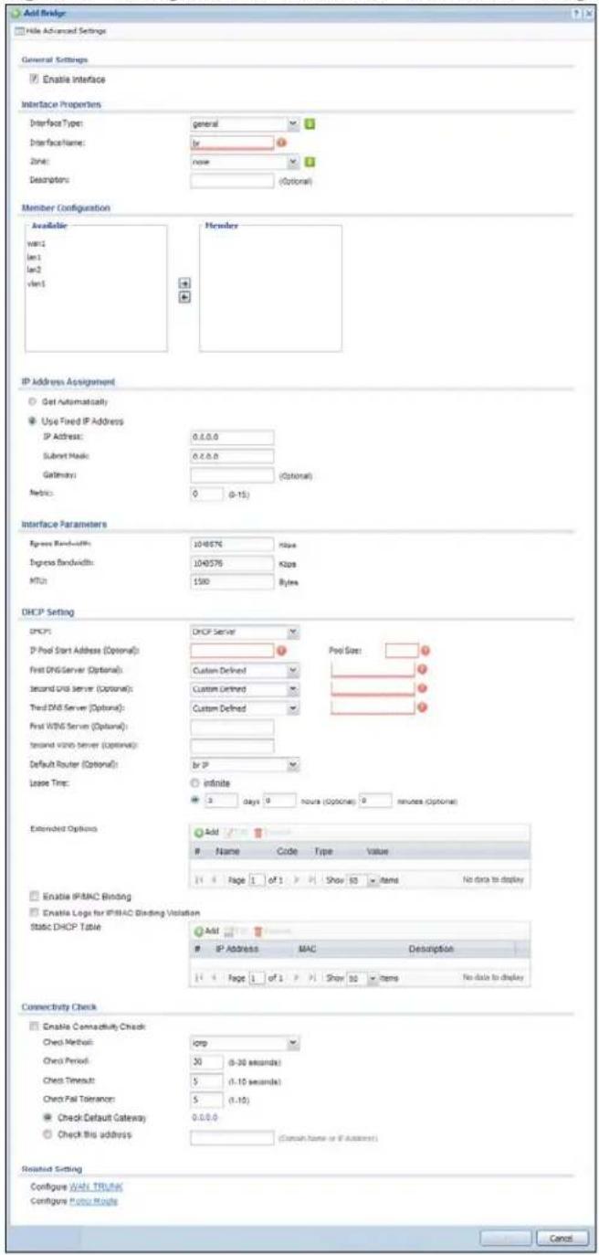
text_image
Add Bridge File Advanced Settings General Settings Enable Interface Interface Properties Interface Type: general Interface Name: by Zone: none Descriptors: (Optional) Member Configuration Available: w011 len1 len2 ven1 Member IP Address Assignment Get Automatically Use Fixed IP Address IP Address: 0.0.0.0 Subrot Mask: 0.0.0.0 Gateway: (Optional) Metric: 0 (0-15) Interface Parameters Express Bandwidth: 104876 hize Ingress Bandwidth: 104876 Kbps MTU: 150 Bytes DHCP Setting DHCP: DHCP Server IP Pool Start Address (Optional): First DHCP Server (Optional): Custom Defined Second Unit Server (Optional): Custom Defined Third DHCP Server (Optional): Custom Defined First WING Server (Optional): Second Viano server (Optional): Default Router (Optional): by IP Lease Tim: infinite 3 days 0 hours (Optional) 0 minutes (Optional) Extended Options Add #Name Code Type Value
14 Page 1 of 1 Show 10 Items No data to display Enable IFRMAC Binding Enable Logs for IFRMAC Binding Violation Static DHCP Table Add # IP Address MAC Description 14 Page 1 of 1 Show 10 Items No data to display Connectivity Check Enable Connectivity Check Check Method: orp Check Period: 30 (0-30 seconds) Check Timeout: 5 (0-15 seconds) Check Fail Tolerance: 5 (1.10) Check Default Gateway: 0.0.0.0 Check this address (Common name or if Account) Revised Setting Configure Web Trukey Configure Fubo Route CancelEach field is described in the table below.
Table 64 Configuration > Network > Interface > Bridge > Add/Edit
| LABEL DESCRIPTION | |
| Show Advanced Settings / Hide Advanced Settings | Click this button to display a greater or lesser number of configuration fields. |
| General Settings | |
| Enable Interface | Select this to enable this interface. Clear this to disable this interface. |
| Interface Properties | |
| Interface Type | Select one of the following option depending on the type of network to which the UAG is connected or if you want to additionally manually configure some related settings.internalis for connecting to a local network. Other corresponding configuration options: DHCP server and DHCP relay. The UAG automatically adds default SNAT settings for traffic flowing from this interface to an external interface.externalis for connecting to an external network (like the Internet). The UAG automatically adds this interface to the default WAN trunk.Forgeneral, the rest of the screen's options do not automatically adjust and you must manually configure a policy route to add routing and SNAT settings for the interface. |
| Interface Name | This field is read-only if you are editing the interface. Enter the name of the bridge interface. The format is brx, where x is 0 - 11. For example, br0, br3, and so on. |
| Zone | Select the zone to which the interface is to belong. You use zones to apply security settings such as firewall, and remote management. |
| Description | Enter a description of this interface. It is not used elsewhere. You can use alphanumeric and () +/ :=?! *#@_-%- characters, and it can be up to 60 characters long. |
| Member Configuration | |
| Available This field | displays Ethernet interfaces and VLAN interfaces that can become part of the bridge interface. An interface is not available in the following situations:There is a virtual interface on top of itIt is already used in a different bridge interfaceSelect one, and click the >> arrow to add it to the bridge interface. Each bridge interface can only have one VLAN interface. |
| Member | This field displays the interfaces that are part of the bridge interface. Select one, and click the << arrow to remove it from the bridge interface. |
| IP Address Assignment | |
| Get Automatically | Select this if this interface is a DHCP client. In this case, the DHCP server configures the IP address, subnet mask, and gateway automatically. |
| Use Fixed IP Address | Select this if you want to specify the IP address, subnet mask, and gateway manually. |
| IP Address | This field is enabled if you select Use Fixed IP Address.Enter the IP address for this interface. |
| Subnet Mask | This field is enabled if you select Use Fixed IP Address.Enter the subnet mask of this interface in dot decimal notation. The subnet mask indicates what part of the IP address is the same for all computers in the network. |
| Gateway | This field is enabled if you select Use Fixed IP Address.Enter the IP address of the gateway. The UAG sends packets to the gateway when it does not know how to route the packet to its destination. The gateway should be on the same network as the interface. |
| Metric | Enter the priority of the gateway (if any) on this interface. The UAG decides which gateway to use based on this priority. The lower the number, the higher the priority. If two or more gateways have the same priority, the UAG uses the one that was configured first. |
| Interface Parameters | |
| Egress Bandwidth | Enter the maximum amount of traffic, in kilobits per second, the UAG can send through the interface to the network. Allowed values are 0 - 1048576. |
| Ingress Bandwidth | This is reserved for future use.Enter the maximum amount of traffic, in kilobits per second, the UAG can receive from the network through the interface. Allowed values are 0 - 1048576. |
| MTU Maximum Transmission Unit. Type the maximum size of each data packet, in bytes, that can move through this interface. If a larger packet arrives, the UAG divides it into smaller fragments. Allowed values are 576 - 1500. Usually, this value is 1500. | |
| DHCP Setting | |
| DHCP Select what type of DHCP service the UAG provides to the network. Choices are: None - the UAG does not provide any DHCP services. There is already a DHCP server on the network.DHCP Relay - the UAG routes DHCP requests to one or more DHCP servers you specify. The DHCP server(s) may be on another network.DHCP Server - the UAG assigns IP addresses and provides subnet mask, gateway, and DNS server information to the network. The UAG is the DHCP server for the network. | |
| These fields appear if the UAG is a DHCP Relay. | |
| Relay Server 1 Enter the IP address of a DHCP server for the network. | |
| Relay Server 2 | This field is optional. Enter the IP address of another DHCP server for the network. |
| These fields appear if the UAG is a DHCP Server. | |
| IP Pool Start Address | Enter the IP address from which the UAG begins allocating IP addresses. If you want to assign a static IP address to a specific computer, click Add Static DHCP.If this field is blank, the Pool Size must also be blank. In this case, the UAG can assign every IP address allowed by the interface's IP address and subnet mask, except for the first address (network address), last address (broadcast address) and the interface's IP address. |
| Pool Size | Enter the number of IP addresses to allocate. This number must be at least one and is limited by the interface's Subnet Mask. For example, if the Subnet Mask is 255.255.255.0 and IP Pool Start Address is 10.10.10.10, the UAG can allocate 10.10.10.10 to 10.10.10.254, or 245 IP addresses.If this field is blank, the IP Pool Start Address must also be blank. In this case, the UAG can assign every IP address allowed by the interface's IP address and subnet mask, except for the first address (network address), last address (broadcast address) and the interface's IP address. |
| First DNS Server Second DNS Server Third DNS Server | Specify the IP addresses up to three DNS servers for the DHCP clients to use. Use one of the following ways to specify these IP addresses.Custom Defined - enter a static IP address.From ISP - select the DNS server that another interface received from its DHCP server.Device - the DHCP clients use the IP address of this interface and the UAG works as a DNS relay. |
| First WINS Server, Second WINS Server | Type the IP address of the WINS (Windows Internet Naming Service) server that you want to send to the DHCP clients. The WINS server keeps a mapping table of the computer names on your network and the IP addresses that they are currently using. |
| Default Router | If you set this interface to DHCP Server, you can select to use either the interface's IP address or another IP address as the default router. This default router will become the DHCP clients' default gateway.To use another IP address as the default router, select Custom Defined and enter the IP address. |
| Lease time Specify | how long each computer can use the information (especially the IP address) before it has to request the information again. Choices are:infinite - select this if IP addresses never expiredays, hours, and minutes - select this to enter how long IP addresses are valid. |
| Extended Options | This table is available if you selected DHCP server.Configure this table if you want to send more information to DHCP clients through DHCP packets. |
| Add | Click this to create an entry in this table. See Section 10.3.3 on page 130. |
| Edit Select an entry in this table and click this to modify it. | |
| Remove Select an entry in this table and click this to delete it. | |
| # This field is a sequential value, and it is not associated with any entry. | |
| Name This is the name of the DHCP option. | |
| Code This is the code number of the DHCP option. | |
| Type This is the type of the set value for the DHCP option. | |
| Value This is the value set for the DHCP option. | |
| Enable IP/MAC Binding | Select this option to have this interface enforce links between specific IP addresses and specific MAC addresses. This stops anyone else from manually using a bound IP address on another device connected to this interface. Use this to make use only the intended users get to use specific IP addresses. |
| Enable Logs for IP/MAC Binding Violation | Select this option to have the UAG generate a log if a device connected to this interface attempts to use an IP address that is bound to another device's MAC address. |
| Static DHCP Table | Configure a list of static IP addresses the UAG assigns to computers connected to the interface. Otherwise, the UAG assigns an IP address dynamically using the interface's IP Pool Start Address and Pool Size. |
| Add Click this to create a new entry. | |
| Edit Select an entry and click this to be able to modify it. | |
| Remove Select an entry and click this to delete it. | |
| # | This field is a sequential value, and it is not associated with a specific entry. |
| IP Address | Enter the IP address to assign to a device with this entry's MAC address. |
| MAC Address | Enter the MAC address to which to assign this entry's IP address. |
| Description | Enter a description to help identify this static DHCP entry. You can use alphanumeric and () +/ := ? ! * @ _ % - characters, and it can be up to 60 characters long. |
| Connectivity Check | The interface can regularly check the connection to the gateway you specified to make sure it is still available. You specify how often the interface checks the connection, how long to wait for a response before the attempt is a failure, and how many consecutive failures are required before the UAG stops routing to the gateway. The UAG resumes routing to the gateway the first time the gateway passes the connectivity check. |
| Enable Connectivity Check | Select this to turn on the connection check. |
| Check Method Select the method that the gateway allows.Select icmp to have the UAG regularly ping the gateway you specify to make sure it is still available.Select tcp to have the UAG regularly perform a TCP handshake with the gateway you specify to make sure it is still available. | |
| Check Period Enter the number of seconds between connection check attempts. | |
| Check Timeout | Enter the number of seconds to wait for a response before the attempt is a failure. |
| Check Fail Tolerance | Enter the number of consecutive failures before the UAG stops routing through the gateway. |
| Check Default Gateway | Select this to use the default gateway for the connectivity check. |
| Check this address | Select this to specify a domain name or IP address for the connectivity check. Enter that domain name or IP address in the field next to it. |
| Check Port | This field only displays when you set the Check Method to tcp. Specify the port number to use for a TCP connectivity check. |
| Related Setting | |
| Configure WAN TRUNK | Click WAN TRUNK to go to a screen where you can configure the interface as part of a WAN trunk for load balancing. |
| Configure Policy Route | Click Policy Route to go to the screen where you can manually configure a policy route to associate traffic with this bridge interface. |
| OK | Click OK to save your changes back to the UAG. |
| Cancel | Click Cancel to exit this screen without saving. |
10.7 Virtual Interfaces
Use virtual interfaces to tell the UAG where to route packets.
Virtual interfaces can be created on top of Ethernet interfaces, VLAN interfaces, or bridge interfaces. Virtual VLAN interfaces recognize and use the same VLAN ID. Otherwise, there is no difference between each type of virtual interface. Network policies (for example, firewall rules) that apply to the underlying interface automatically apply to the virtual interface as well.
Like other interfaces, virtual interfaces have an IP address, subnet mask, and gateway used to make routing decisions. However, you have to manually specify the IP address and subnet mask; virtual interfaces cannot be DHCP clients. Like other interfaces, you can restrict bandwidth through virtual interfaces, but you cannot change the MTU. The virtual interface uses the same MTU that the underlying interface uses. Unlike other interfaces, virtual interfaces do not provide DHCP services, and they do not verify that the gateway is available.
10.7.1 Virtual Interfaces Add/Edit
This screen lets you configure IP address assignment and interface parameters for virtual interfaces. To access this screen, click the Create Virtual Interface icon in the Ethernet, VLAN, or bridge interface summary screen.
Figure 95 Configuration > Network > Interface > Create Virtual Interface

text_image
Create Virtual Interface Interface Properties Interface Name: wan1:1 Description: (Optional) IP Address Assignment IP Address: 0.0.0.0 Subnet Mask: 0.0.0.0 Gateway: (Optional) Metric: 0 (0..15) Interface Parameters Egress Bandwidth: 1048576 Kbps Ingress Bandwidth: 1048576 Kbps OK CancelEach field is described in the table below.
Table 65 Configuration > Network > Interface > Create Virtual Interface
| LABEL DESCRIPTION | |
| Interface Properties | |
| Interface Name | This field is read-only. It displays the name of the virtual interface, which is automatically derived from the underlying Ethernet interface, VLAN interface, or bridge interface. |
| Description | Enter a description of this interface. It is not used elsewhere. You can use alphanumeric and () +/ :=?! *#@$_%- characters, and it can be up to 60 characters long. |
| IP Address Assignment | |
| IP Address Enter the IP address for this interface. | |
| Subnet Mask | Enter the subnet mask of this interface in dot decimal notation. The subnet mask indicates what part of the IP address is the same for all computers in the network. |
| Gateway Enter the IP address of the gateway. The UAG sends packets to the gateway when it does not know how to route the packet to its destination. The gateway should be on the same network as the interface. | |
| Metric | Enter the priority of the gateway (if any) on this interface. The UAG decides which gateway to use based on this priority. The lower the number, the higher the priority. If two or more gateways have the same priority, the UAG uses the one that was configured first. |
| Interface Parameters | |
| Egress Bandwidth | Enter the maximum amount of traffic, in kilobits per second, the UAG can send through the interface to the network. Allowed values are 0 - 1048576. |
| Ingress Bandwidth | This is reserved for future use.Enter the maximum amount of traffic, in kilobits per second, the UAG can receive from the network through the interface. Allowed values are 0 - 1048576. |
| OK | Click OK to save your changes back to the UAG. |
| Cancel | Click Cancel to exit this screen without saving. |
10.8 Interface Technical Reference
Here is more detailed information about interfaces on the UAG.
IP Address Assignment
Most interfaces have an IP address and a subnet mask. This information is used to create an entry in the routing table.
Figure 96 Example: Entry in the Routing Table Derived from Interfaces
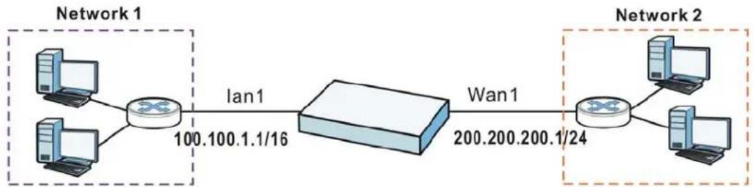
Table 66 Example: Routing Table Entries for Interfaces
| IP ADDRESS(ES) DESTINATION | |
| 100.100.1.1/16 lan1 | |
| 200.200.200.1/24 wan1 | |
For example, if the UAG gets a packet with a destination address of 100.100.25.25, it routes the packet to interface lan1. If the UAG gets a packet with a destination address of 200.200.200.200, it routes the packet to interface wan1.
In most interfaces, you can enter the IP address and subnet mask manually. In PPPoE/PPTP interfaces, however, the subnet mask is always 255.255.255.255 because it is a point-to-point interface. For these interfaces, you can only enter the IP address.
In many interfaces, you can also let the IP address and subnet mask be assigned by an external DHCP server on the network. In this case, the interface is a DHCP client. Virtual interfaces, however, cannot be DHCP clients. You have to assign the IP address and subnet mask manually.
In general, the IP address and subnet mask of each interface should not overlap, though it is possible for this to happen with DHCP clients.
In the example above, if the UAG gets a packet with a destination address of 5.5.5.5, it might not find any entries in the routing table. In this case, the packet is dropped. However, if there is a default router to which the UAG should send this packet, you can specify it as a gateway in one of the interfaces. For example, if there is a default router at 200.200.200.100, you can create a gateway at 200.200.200.100 on wan1. In this case, the UAG creates the following entry in the routing table.
Table 67 Example: Routing Table Entry for a Gateway
| IP ADDRESS(ES) DESTINATION |
| 0.0.0.0/0 200.200.200.100 |
The gateway is an optional setting for each interface. If there is more than one gateway, the UAG uses the gateway with the lowest metric, or cost. If two or more gateways have the same metric, the UAG uses the one that was set up first (the first entry in the routing table). In PPPoE/PPTP interfaces, the other computer is the gateway for the interface by default. In this case, you should specify the metric.
If the interface gets its IP address and subnet mask from a DHCP server, the DHCP server also specifies the gateway, if any.
Interface Parameters
The UAG restricts the amount of traffic into and out of the UAG through each interface.
- Egress bandwidth sets the amount of traffic the UAG sends out through the interface to the network.
- Ingress bandwidth sets the amount of traffic the UAG allows in through the interface from the network. ^1
If you set the bandwidth restrictions very high, you effectively remove the restrictions.
The UAG also restricts the size of each data packet. The maximum number of bytes in each packet is called the maximum transmission unit (MTU). If a packet is larger than the MTU, the UAG divides it into smaller fragments. Each fragment is sent separately, and the original packet is re-assembled later. The smaller the MTU, the more fragments sent, and the more work required to re-assemble packets correctly. On the other hand, some communication channels, such as Ethernet over ATM, might not be able to handle large data packets.
DHCP Settings
Dynamic Host Configuration Protocol (DHCP, RFC 2131, RFC 2132) provides a way to automatically set up and maintain IP addresses, subnet masks, gateways, and some network information (such as the IP addresses of DNS servers) on computers in the network. This reduces the amount of manual configuration you have to do and usually uses available IP addresses more efficiently.
In DHCP, every network has at least one DHCP server. When a computer (a DHCP client) joins the network, it submits a DHCP request. The DHCP servers get the request; assign an IP address; and provide the IP address, subnet mask, gateway, and available network information to the DHCP client. When the DHCP client leaves the network, the DHCP servers can assign its IP address to another DHCP client.
In the UAG, some interfaces can provide DHCP services to the network. In this case, the interface can be a DHCP relay or a DHCP server.
As a DHCP relay, the interface routes DHCP requests to DHCP servers on different networks. You can specify more than one DHCP server. If you do, the interface routes DHCP requests to all of them. It is possible for an interface to be a DHCP relay and a DHCP client simultaneously.
As a DHCP server, the interface provides the following information to DHCP clients.
- IP address - If the DHCP client's MAC address is in the UAG's static DHCP table, the interface assigns the corresponding IP address. If not, the interface assigns IP addresses from a pool, defined by the starting address of the pool and the pool size.
Table 68 Example: Assigning IP Addresses from a Pool
| START IP ADDRESS POOL SIZE | RANGE OF ASSIGNED IP ADDRESS |
| 50.50.50.33 5 50.50.50.33 - 50.50 | 50.37 |
| 75.75.75.1 200 75.75.75.1 - 75.75 | 75.200 |
| 99.99.1.1 1023 99.99.1.1 - 99.99 | 4.255 |
| 120.120.120.100 100 120.120.120 | 100 - 120.120.120.199 |
The UAG cannot assign the first address (network address) or the last address (broadcast address) in the subnet defined by the interface's IP address and subnet mask. For example, in the first entry, if the subnet mask is 255.255.255.0, the UAG cannot assign 50.50.50.0 or 50.50.50.255. If the subnet mask is 255.255.0.0, the UAG cannot assign 50.50.0.0 or 50.50.255.255. Otherwise, it can assign every IP address in the range, except the interface's IP address.
If you do not specify the starting address or the pool size, the interface the maximum range of IP addresses allowed by the interface's IP address and subnet mask. For example, if the interface's IP address is 9.9.9.1 and subnet mask is 255.255.255.0, the starting IP address in the pool is 9.9.9.2, and the pool size is 253.
- Subnet mask - The interface provides the same subnet mask you specify for the interface. See IP Address Assignment on page 154.
- Gateway - The interface provides the same gateway you specify for the interface. See IP Address Assignment on page 154.
- DNS servers - The interface provides IP addresses for up to three DNS servers that provide DNS services for DHCP clients. You can specify each IP address manually (for example, a company's own DNS server), or you can refer to DNS servers that other interfaces received from DHCP servers (for example, a DNS server at an ISP). These other interfaces have to be DHCP clients.
It is not possible for an interface to be the DHCP server and a DHCP client simultaneously.
WINS
WINS (Windows Internet Naming Service) is a Windows implementation of NetBIOS Name Server (NBNS) on Windows. It keeps track of NetBIOS computer names. It stores a mapping table of your network's computer names and IP addresses. The table is dynamically updated for IP addresses assigned by DHCP. This helps reduce broadcast traffic since computers can query the server instead of broadcasting a request for a computer name's IP address. In this way WINS is similar to DNS, although WINS does not use a hierarchy (unlike DNS). A network can have more than one WINS server. Samba can also serve as a WINS server.
PPPoE/PPTP Overview
Point-to-Point Protocol over Ethernet (PPPoE, RFC 2516) and Point-to-Point Tunneling Protocol (PPTP, RFC 2637) are usually used to connect two computers over phone lines or broadband connections. PPPoE is often used with cable modems and DSL connections. It provides the following advantages:
- The access and authentication method works with existing systems, including RADIUS.
- You can access one of several network services. This makes it easier for the service provider to offer the service
- PPPoE does not usually require any special configuration of the modem.
PPTP is used to set up virtual private networks (VPN) in unsecure TCP/IP environments. It sets up two sessions.
1 The first one runs on TCP port 1723. It is used to start and manage the second one.
2 The second one uses Generic Routing Encapsulation (GRE, RFC 2890) to transfer information between the computers.
PPTP is convenient and easy-to-use, but you have to make sure that firewalls support both PPTP sessions.
11.1 Overview
Use trunks for WAN traffic load balancing to increase overall network throughput and reliability. Load balancing divides traffic loads between multiple interfaces. This allows you to improve quality of service and maximize bandwidth utilization for multiple ISP links.
Maybe you have two Internet connections with different bandwidths. You could set up a trunk that uses spillover or weighted round robin load balancing so time-sensitive traffic (like video) usually goes through the higher-bandwidth interface. For other traffic, you might want to use least load first load balancing to even out the distribution of the traffic load.
Suppose ISP A has better connections to Europe while ISP B has better connections to Australia. You could use policy routes and trunks to have traffic for your European branch office primarily use ISP A and traffic for your Australian branch office primarily use ISP B.
Or maybe one of the UAG's interfaces is connected to an ISP that is also your Voice over IP (VoIP) service provider. You can use policy routing to send the VoIP traffic through a trunk with the interface connected to the VoIP service provider set to active and another interface (connected to another ISP) set to passive. This way VoIP traffic goes through the interface connected to the VoIP service provider whenever the interface's connection is up.
11.1.1 What You Can Do in this Chapter
- Use the Trunk summary screen (Section 11.2 on page 161) to configure link sticking and view the list of configured trunks and which load balancing algorithm each trunk uses.
- Use the Add Trunk screen (Section 11.2.1 on page 162) to configure the member interfaces for a trunk and the load balancing algorithm the trunk uses.
- Use the Add System Default screen (Section 11.2.2 on page 164) to configure the load balancing algorithm for the system default trunk.
11.1.2 What You Need to Know
- Add WAN interfaces to trunks to have multiple connections share the traffic load.
- If one WAN interface's connection goes down, the UAG sends traffic through another member of the trunk.
- For example, you connect one WAN interface to one ISP and connect a second WAN interface to a second ISP. The UAG balances the WAN traffic load between the connections. If one interface's connection goes down, the UAG can automatically send its traffic through another interface.
You can also use trunks with policy routing to send specific traffic types through the best WAN interface for that type of traffic.
- If that interface's connection goes down, the UAG can still send its traffic through another interface.
- You can define multiple trunks for the same physical interfaces.
Load Balancing Algorithms
The following sections describe the load balancing algorithms the UAG can use to decide which interface the traffic (from the LAN) should use for a session ^2 . The available bandwidth you configure on the UAG refers to the actual bandwidth provided by the ISP and the measured bandwidth refers to the bandwidth an interface is currently using.
Least Load First
The least load first algorithm uses the current (or recent) outbound bandwidth utilization of each trunk member interface as the load balancing index(es) when making decisions about to which interface a new session is to be distributed. The outbound bandwidth utilization is defined as the measured outbound throughput over the available outbound bandwidth.
Here the UAG has two WAN interfaces connected to the Internet. The configured available outbound bandwidths for wan1 and ppp0 are 512K and 256K respectively.
Figure 97 Least Load First Example

flowchart
graph LR
    A["SCAN1\n512K"] --> B["INTERNET"]
    C["PPP0\n256K"] --> B
The outbound bandwidth utilization is used as the load balancing index. In this example, the measured (current) outbound throughput of wan1 is 412K and ppp0 is 198K. The UAG calculates the load balancing index as shown in the table below.
Since ppp0 has a smaller load balancing index (meaning that it is less utilized than wan1), the UAG will send the subsequent new session traffic through ppp0.
Table 69 Least Load First Example
| INTERFACE | OUTBOUND | LOAD BALANCING INDEX (M/A) | |
| AVAILABLE (A) MEASURED (M) | |||
| wan1 512 K 412 K | 0.8 | ||
| ppp0 256 K 198 K | 0.77 | ||
Weighted Round Robin
Round Robin scheduling services queues on a rotating basis and is activated only when an interface has more traffic than it can handle. A queue is given an amount of bandwidth irrespective of the incoming traffic on that interface. This queue then moves to the back of the list. The next queue is
given an equal amount of bandwidth, and then moves to the end of the list; and so on, depending on the number of queues being used. This works in a looping fashion until a queue is empty.
The Weighted Round Robin (WRR) algorithm is best suited for situations when the bandwidths set for the two WAN interfaces are different. Similar to the Round Robin (RR) algorithm, the Weighted Round Robin (WRR) algorithm sets the UAG to send traffic through each WAN interface in turn. In addition, the WAN interfaces are assigned weights. An interface with a larger weight gets more chances to transmit traffic than an interface with a smaller weight.
For example, in the figure below, the configured available bandwidth of wan1 is 1M and ppp0 is 512K. You can set the UAG to distribute the network traffic between the two interfaces by setting the weight of wan1 and ppp0 to 2 and 1 respectively. The UAG assigns the traffic of two sessions to wan1 and one session's traffic to ppp0 in each round of 3 new sessions.
Figure 98 Weighted Round Robin Algorithm Example

flowchart
graph LR
    S6 --> S4
    S2 --> S1
    S3 --> S2
    S1 --> wan1["wan1 1M"]
    S3 --> ppp0["ppp0 512K"]
    wan1 --> INTERNET["INTERNET"]
    ppp0 --> INTERNET
Spillover
The spillover load balancing algorithm sends network traffic to the first interface in the trunk member list until the interface's maximum allowable load is reached, then sends the excess network traffic of new sessions to the next interface in the trunk member list. This continues as long as there are more member interfaces and traffic to be sent through them.
Suppose the first trunk member interface uses an unlimited access Internet connection and the second is billed by usage. Spillover load balancing only uses the second interface when the traffic load exceeds the threshold on the first interface. This fully utilizes the bandwidth of the first interface to reduce Internet usage fees and avoid overloading the interface.
In this example figure, the upper threshold of the first interface is set to 800K. The UAG sends network traffic of new sessions that exceed this limit to the secondary WAN interface.
Figure 99 Spillover Algorithm Example
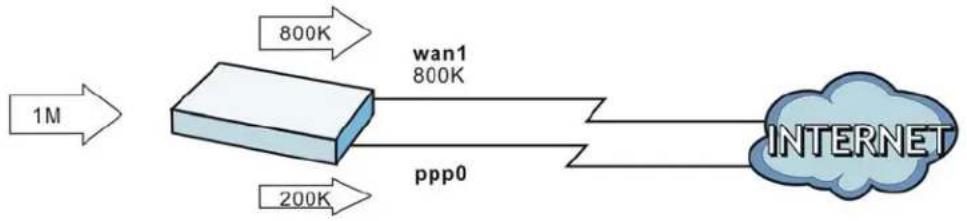
flowchart
graph LR
    A["1M"] --> B["800K"]
    B --> C["wan1\n800K"]
    C --> D["Internet"]
    E["200K"] --> F["ppp0"]
11.2 The Trunk Summary Screen
Click Configuration > Network > Interface > Trunk to open the Trunk screen. This screen lists the configured trunks and the load balancing algorithm that each is configured to use.
Figure 100 Configuration > Network > Interface > Trunk
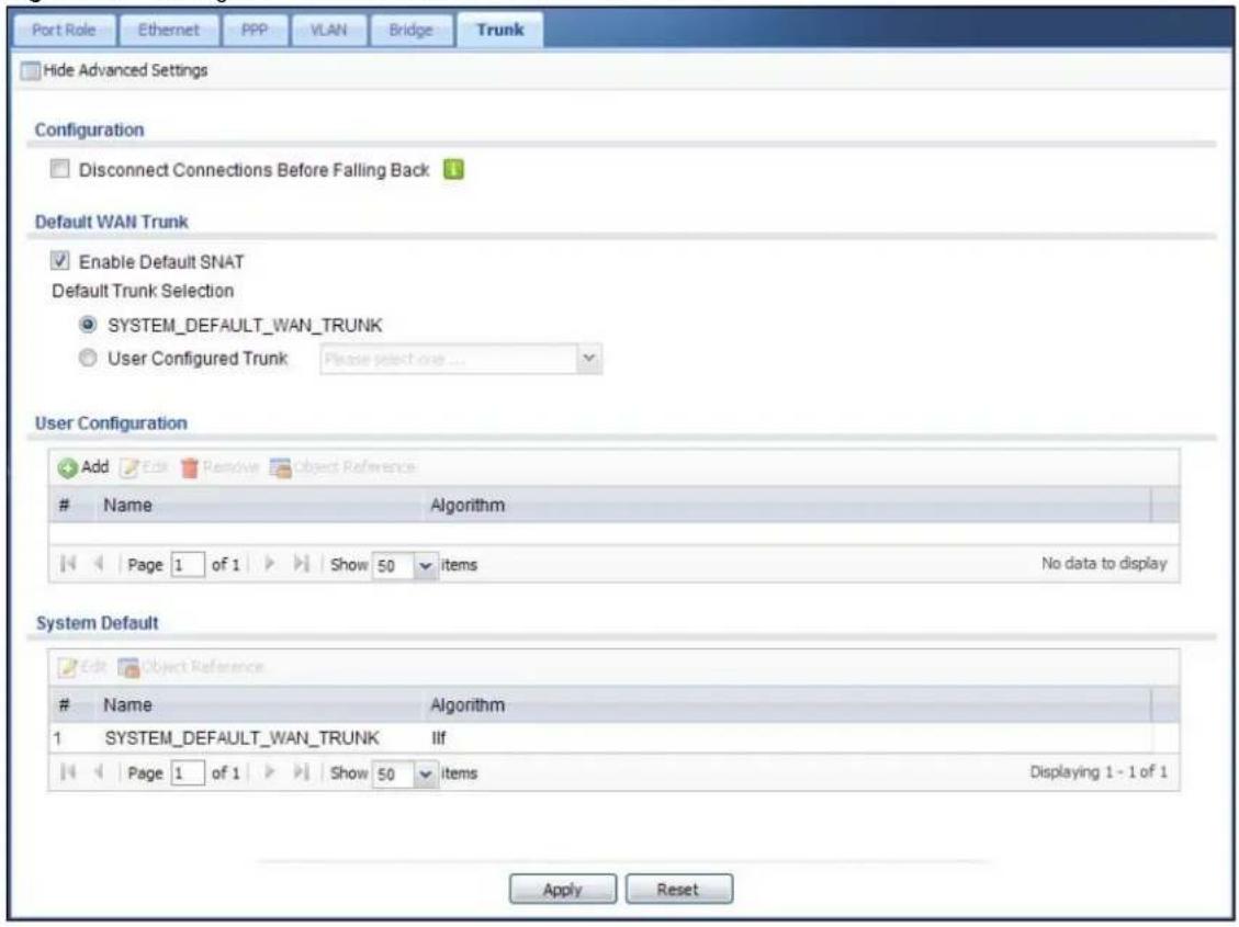
text_image
Port Role Ethernet PPP VLAN Bridge Trunk Hide Advanced Settings Configuration Disconnect Connections Before Falling Back Default WAN Trunk Enable Default SNAT Default Trunk Selection SYSTEM_DEFAULT_WAN_TRUNK User Configured Trunk Please select one ... User Configuration Add Edit Remove Object ReferenceName Algorithm
Page 1 of 1 Show 50 items No data to display System Default Edit Object ReferenceName Algorithm
1 SYSTEM_DEFAULT_WAN_TRUNK Ifl Page 1 of 1 Show 50 items Displaying 1 - 1 of 1 Apply ResetThe following table describes the items in this screen.
Table 70 Configuration > Network > Interface > Trunk
| LABEL DESCRIPTION | |
| Show Advanced Settings / Hide Advanced Settings | Click this button to display a greater or lesser number of configuration fields. |
| Disconnect Connections Before Falling Back | Select this to terminate existing connections on an interface which is set to passive mode when any interface set to active mode in the same trunk comes back up. |
| Enable Default SNAT | Select this to have the UAG use the IP address of the outgoing interface as the source IP address of the packets it sends out through its WAN trunks. The UAG automatically adds SNAT settings for traffic it routes from internal interfaces to external interfaces. |
| Default Trunk Selection | Select whether the UAG is to use the default system WAN trunk or one of the user configured WAN trunks as the default trunk for routing traffic from internal interfaces to external interfaces. |
| User Configuration / System Default | The UAG automatically adds all external interfaces into the pre-configured system default SYSTEM_DEFAULT_WAN_TRUNC. You cannot delete it. You can create your own User Configuration trunks and customize the algorithm, member interfaces and the active/passive mode. |
| Add Click this to create a new user-configured trunk. | |
| Edit | Double-click an entry or select it and click Edit to open a screen where you can modify the entry's settings. |
| Remove | To remove a user-configured trunk, select it and click Remove. The UAG confirms you want to remove it before doing so. |
| Object Reference | Select an entry and click Object Reference to open a screen that shows which settings use the entry. See Section 10.3.2 on page 129 for an example. |
| # This field is a sequential value, and it is not associated with any interface. | |
| Name This field displays the label that you specified to identify the trunk. | |
| Algorithm This field displays the load balancing method the trunk is set to use. | |
| Apply Click this button to save your changes to the UAG. | |
| Reset Click this button to return the screen to its last-saved settings. | |
11.2.1 Configuring a User-Defined Trunk
Click Configuration > Network > Interface > Trunk, in the User Configuration table click the Add (or Edit) icon to open the Add/Edit Trunk screen. Use this screen to create or edit a WAN trunk entry.
Figure 101 Configuration > Network > Interface > Trunk > Add/Edit
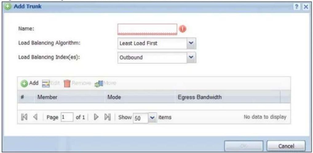
text_image
Add Trunk Name: Load Balancing Algorithm: Least Load First Load Balancing Index(es): Outbound Add Edit Remove MoveMember Mode Egress Bandwidth
Page 1 of 1 Show 50 items No data to display OK CancelEach field is described in the table below.
Table 71 Configuration > Network > Interface > Trunk > Add/Edit
| LABEL DESCRIPTION | |
| Name | This is read-only if you are editing an existing trunk. When adding a new trunk, enter a descriptive name for this trunk. You may use 1-31 alphanumeric characters, underscores (_, or dashes (-), but the first character cannot be a number. This value is case-sensitive. |
| Load Balancing Algorithm | Select a load balancing method to use from the drop-down list box.SelectWeighted Round Robinto balance the traffic load between interfaces based on their respective weights. An interface with a larger weight gets more chances to transmit traffic than an interface with a smaller weight. For example, if the weight ratio of wan1 and ppp0 interfaces is 2:1, the UAG chooses wan1 for 2 sessions' traffic and ppp0 for 1 session's traffic in each round of 3 new sessions.SelectLeast Load Firstto send new session traffic through the least utilized trunk member.SelectSpilloverto send network traffic through the first interface in the group member list until there is enough traffic that the second interface needs to be used (and so on). |
| Load Balancing Index(es) | This field is available if you selected to use theLeast Load FirstorSpillovermethod.SelectOutbound, Inbound, orOutbound + Inboundto set the traffic to which the UAG applies the load balancing method. Outbound means the traffic traveling from an internal interface (ex. LAN) to an external interface (ex. WAN). Inbound means the opposite. |
| The table lists the trunk's member interfaces. You can add, edit, remove, or move entries for user configured trunks. | |
| Add | Click this to add a member interface to the trunk. Select an interface and clickAddto add a new member interface after the selected member interface. |
| Edit | Select an entry and clickEditto modify the entry's settings. |
| Remove | To remove a member interface, select it and clickRemove. The UAG confirms you want to remove it before doing so. |
| Move | To move an interface to a different number in the list, click theMoveicon. In the field that appears, specify the number to which you want to move the interface. |
| # | This column displays the priorities of the group's interfaces. The order of the interfaces in the list is important since they are used in the order they are listed. |
| Member Click this | table cell and select an interface to be a group member. |
| Mode | Click this table cell and selectActiveto have the UAG always attempt to use this connection.SelectPassiveto have the UAG only use this connection when all of the connections set to active are down. You can only set one of a group's interfaces to passive mode. |
| Weight | This field displays with the weighted round robin load balancing algorithm. Specify the weight (1~10) for the interface. The weights of the different member interfaces form a ratio. This ratio determines how much traffic the UAG assigns to each member interface. The higher an interface's weight is (relative to the weights of the interfaces), the more sessions that interface should handle. |
| Ingress Bandwidth | This is reserved for future use.This field displays with the least load first load balancing algorithm. It displays the maximum number of kilobits of data the UAG is to allow to come in through the interface per second.Note: You can configure the bandwidth of an interface in the corresponding interface edit screen. |
| Egress Bandwidth | This field displays with the least load first or spillover load balancing algorithm. It displays the maximum number of kilobits of data the UAG is to send out through the interface per second.Note: You can configure the bandwidth of an interface in the corresponding interface edit screen. |
| Total Bandwidth | This field displays with the spillover load balancing algorithm. It displays the maximum number of kilobits of data the UAG is to send out and allow to come in through the interface per second.You can configure the bandwidth of an interface in the corresponding interface edit screen. |
| Spillover This field | displays with the spillover load balancing algorithm. Specify the maximum bandwidth of traffic in kilobits per second (1~1048576) to send out through the interface before using another interface. When this spillover bandwidth limit is exceeded, the UAG sends new session traffic through the next interface. The traffic of existing sessions still goes through the interface on which they started.The UAG uses the group member interfaces in the order that they are listed. |
| OK | Click OK to save your changes back to the UAG. |
| Cancel | Click Cancel to exit this screen without saving. |
11.2.2 Configuring the System Default Trunk
In the Configuration > Network > Interface > Trunk screen and the System Default section, select the default trunk entry and click Edit to open the Edit System Default screen. Use this screen to change the load balancing algorithm and view the bandwidth allocations for each member interface.
Note: The available bandwidth is allocated to each member interface equally and is not allowed to be changed for the default trunk.
Figure 102 Configuration > Network > Interface > Trunk > Edit (System Default)
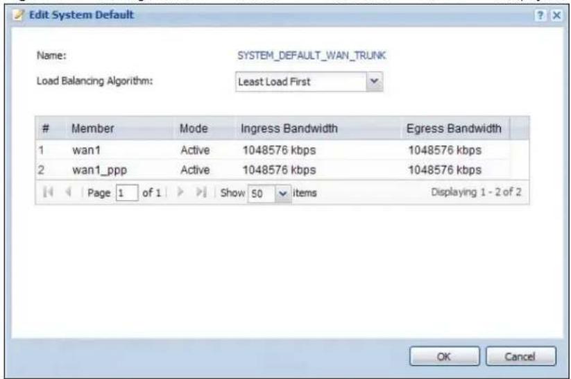
text_image
Edit System Default Name: SYSTEM_DEFAULT_WAN_TRUNK Load Balancing Algorithm: Least Load FirstMember Mode Ingress Bandwidth Egress Bandwidth
1 wan1 Active 1048576 kbps 1048576 kbps 2 wan1_ppp Active 1048576 kbps 1048576 kbps Page 1 of 1 Show 50 items Displaying 1 - 2 of 2 OK CancelEach field is described in the table below.
Table 72 Configuration > Network > Interface > Trunk > Edit (System Default)
| LABEL DESCRIPTION | |
| Name This field displays the name of the selected system default trunk. | |
| Load Balancing Algorithm | Select the load balancing method to use for the trunk.SelectWeighted Round Robinto balance the traffic load between interfaces based on their respective weights. An interface with a larger weight gets more chances to transmit traffic than an interface with a smaller weight. For example, if the weight ratio of wan1 and ppp0 interfaces is 2:1, the UAG chooses wan1 for 2 sessions' traffic and ppp0 for 1 session's traffic in each round of 3 new sessions.SelectLeast Load Firstto send new session traffic through the least utilized trunk member.SelectSpilloverto send network traffic through the first interface in the group member list until there is enough traffic that the second interface needs to be used (and so on). |
| The table lists the trunk's member interfaces. This table is read-only. | |
| # | This column displays the priorities of the group's interfaces. The order of the interfaces in the list is important since they are used in the order they are listed. |
| Member This column displays the name of the member interfaces. | |
| Mode | This field displaysActiveif the UAG always attempt to use this connection.This field displaysPassiveif the UAG only use this connection when all of the connections set to active are down. Only one of a group's interfaces can be set to passive mode. |
| Weight | This field displays with the weighted round robin load balancing algorithm. Specify the weight (1~10) for the interface. The weights of the different member interfaces form a ratio. s |
| Ingress Bandwidth | This is reserved for future use.This field displays with the least load first load balancing algorithm. It displays the maximum number of kilobits of data the UAG is to allow to come in through the interface per second. |
| Egress Bandwidth | This field displays with the least load first or spillover load balancing algorithm. It displays the maximum number of kilobits of data the UAG is to send out through the interface per second. |
| Spillover | This field displays with the spillover load balancing algorithm. Specify the maximum bandwidth of traffic in kilobits per second (1~1048576) to send out through the interface before using another interface. When this spillover bandwidth limit is exceeded, the UAG sends new session traffic through the next interface. The traffic of existing sessions still goes through the interface on which they started.The UAG uses the group member interfaces in the order that they are listed. |
| OK | Click OKto save your changes back to the UAG. |
| Cancel | Click Cancelto exit this screen without saving. |
Policy and Static Routes
12.1 Policy and Static Routes Overview
Use policy routes and static routes to override the UAG's default routing behavior in order to send packets through the appropriate interface.
For example, the next figure shows a computer (A) connected to the UAG's LAN interface. The UAG routes most traffic from A to the Internet through the UAG's default gateway (R1). You create one policy route to connect to services offered by your ISP behind router R2. You create another policy route to communicate with a separate network behind another router (R3) connected to the LAN.
Figure 103 Example of Policy Routing Topology
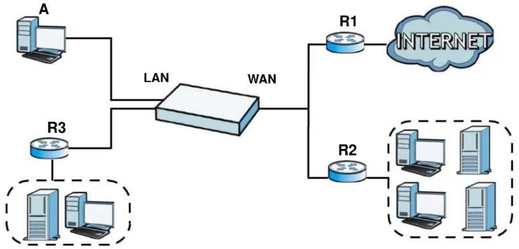
flowchart
graph TD
    A["Router A"] --> LAN
    R3["Router R3"] --> LAN
    LAN --> WAN
    R1["R1"] --> INTERNET["INTERNET"]
    R2["R2"] --> INTERNET
    subgraph LAN
        R3
        R2
    end
    subgraph WAN
        R1
        R2
    end
    style LAN fill:#f9f,stroke:#333
    style WAN fill:#ccf,stroke:#333
12.1.1 What You Can Do in this Chapter
- Use the Policy Route screens (see Section 12.2 on page 168) to list and configure policy routes.
- Use the Static Route screens (see Section 12.3 on page 173) to list and configure static routes.
12.1.2 What You Need to Know
Policy Routing
Traditionally, routing is based on the destination address only and the UAG takes the shortest path to forward a packet. IP Policy Routing (IPPR) provides a mechanism to override the default routing behavior and alter the packet forwarding based on the policy defined by the network administrator.
Policy-based routing is applied to incoming packets on a per interface basis, prior to the normal routing.
How You Can Use Policy Routing
- Source-Based Routing – Network administrators can use policy-based routing to direct traffic from different users through different connections.
- Cost Savings – IPPR allows organizations to distribute interactive traffic on high-bandwidth, high-cost paths while using low-cost paths for batch traffic.
- Load Sharing – Network administrators can use IPPR to distribute traffic among multiple paths.
- NAT - The UAG performs NAT by default for traffic going to or from the WAN interfaces. A routing policy's SNAT allows network administrators to have traffic received on a specified interface use a specified IP address as the source IP address.
Note: The UAG automatically uses SNAT for traffic it routes from internal interfaces to external interfaces. For example LAN to WAN traffic.
Static Routes
The UAG usually uses the default gateway to route outbound traffic from computers on the LAN to the Internet. To have the UAG send data to devices not reachable through the default gateway, use static routes.
Policy Routes Versus Static Routes
- Policy routes are more flexible than static routes. You can select more criteria for the traffic to match and can also use schedules, and NAT.
- Policy routes are only used within the UAG itself.
- Policy routes take priority over static routes. If you need to use a routing policy on the UAG and propagate it to other routers, you could configure a policy route and an equivalent static route.
DiffServ
QoS is used to prioritize source-to-destination traffic flows. All packets in the same flow are given the same priority. CoS (class of service) is a way of managing traffic in a network by grouping similar types of traffic together and treating each type as a class. You can use CoS to give different priorities to different packet types.
DiffServ (Differentiated Services) is a class of service (CoS) model that marks packets so that they receive specific per-hop treatment at DiffServ-compliant network devices along the route based on the application types and traffic flow. Packets are marked with DiffServ Code Points (DSCPs) indicating the level of service desired. This allows the intermediary DiffServ-compliant network devices to handle the packets differently depending on the code points without the need to negotiate paths or remember state information for every flow. In addition, applications do not have to request a particular service or give advanced notice of where the traffic is going.
DSCP Marking and Per-Hop Behavior
DiffServ defines a new DS (Differentiated Services) field to replace the Type of Service (TOS) field in the IP header. The DS field contains a 2-bit unused field and a 6-bit DSCP field which can define up to 64 service levels. The following figure illustrates the DS field.
DSCP (6 bits) Unused (2 bits)
DSCP is backward compatible with the three precedence bits in the ToS octet so that non-DiffServ compliant, ToS-enabled network device will not conflict with the DSCP mapping.
The DSCP value determines the forwarding behavior, the PHB (Per-Hop Behavior), that each packet gets across the DiffServ network. Based on the marking rule, different kinds of traffic can be marked for different kinds of forwarding. Resources can then be allocated according to the DSCP values and the configured policies.
Finding Out More
• See Section 12.4 on page 175 for more background information on policy routing.
12.2 Policy Route Screen
Click Configuration > Network > Routing to open the Policy Route screen. Use this screen to see the configured policy routes.
A policy route defines the matching criteria and the action to take when a packet meets the criteria. The action is taken only when all the criteria are met. The criteria can include the user name, source address and incoming interface, destination address, schedule, IP protocol (ICMP, UDP, TCP, etc.) and port.
The actions that can be taken include:
- Routing the packet to a different gateway, outgoing interface, or trunk.
IPPR follows the existing packet filtering facility of RAS in style and in implementation.
Figure 104 Configuration > Network > Routing > Policy Route

text_image
Policy Route Static Route Hide Advanced Settings Use Policy Route to Override Direct Route Add Edit Remove Activate Inactivate MoveStat... User Schedule Incoming Source Destinat... DSCP C... Service Source ... Next-Hop DSCP M... SNAT
1 any none any (Exc... any any any any any wan1 preserve outgoing-in... Page 1 of 1 Show 50 items Displaying 1 - 1 of 1 Apply ResetThe following table describes the labels in this screen.
Table 73 Configuration > Network > Routing > Policy Route
| LABEL DESCRIPTION | |
| Show Advanced Settings / Hide Advanced Settings | Click this button to display a greater or lesser number of configuration fields. |
| Use Policy Route to Override Direct Route | Select this to have the UAG forward packets that match a policy route according to the policy route instead of sending the packets directly to a connected network. |
| Add | Click this to create a new entry. Select an entry and click Add to create a new entry after the selected entry. |
| Edit | Double-click an entry or select it and click Edit to open a screen where you can modify the entry's settings. |
| Remove | To remove an entry, select it and click Remove. The UAG confirms you want to remove it before doing so. |
| Activate | To turn on an entry, select it and click Activate. |
| Inactivate | To turn off an entry, select it and click Inactivate. |
| Move | To change a rule's position in the numbered list, select the rule and click Move to display a field to type a number for where you want to put that rule and press [ENTER] to move the rule to the number that you typed.The ordering of your rules is important as they are applied in order of their numbering. |
| # This is the number of an individual policy route. | |
| Status | This icon is lit when the entry is active, red when the next hop's connection is down, and dimmed when the entry is inactive. |
| User | This is the name of the user (group) object from which the packets are sent. any means all users. |
| Schedule | This is the name of the schedule object. none means the route is active at all times if enabled. |
| Incoming | This is the interface on which the packets are received. |
| Source | This is the name of the source IP address (group) object. any means all IP addresses. |
| Destination | This is the name of the destination IP address (group) object. any means all IP addresses. |
| DSCP Code | This is the DSCP value of incoming packets to which this policy route applies.any means all DSCP values or no DSCP marker.default means traffic with a DSCP value of 0. This is usually best effort trafficThe "af" entries stand for Assured Forwarding. The number following the "af" identifies one of four classes and one of three drop preferences. See Assured Forwarding (AF) PHB for DiffServ on page 175 for more details. |
| Service | This is the name of the service object. any means all services. |
| Source Port | This is the name of a service object. The UAG applies the policy route to the packets sent from the corresponding service port. any means all service ports. |
| Next-Hop | This is the next hop to which packets are directed. It helps forward packets to their destinations and can be a router, outgoing interface or trunk. |
| DSCP Marking | This is how the UAG handles the DSCP value of the outgoing packets that match this route. If this field displays a DSCP value, the UAG applies that DSCP value to the route's outgoing packets.preserve means the UAG does not modify the DSCP value of the route's outgoing packets.default means the UAG sets the DSCP value of the route's outgoing packets to 0.The “af” choices stand for Assured Forwarding. The number following the “af” identifies one of four classes and one of three drop preferences. See Assured Forwarding (AF) PHB for DiffServ on page 175 for more details. |
| SNAT This is the source IP address that the route uses.It displays none if the UAG does not perform NAT for this route. | |
| Apply Click Apply | to save your changes back to the UAG. |
| Reset | Click Reset to return the screen to its last-saved settings. |
12.2.1 Policy Route Add/Edit Screen
Click Configuration > Network > Routing to open the Policy Route screen. Then click the Add icon or select an entry and click the Edit icon. The Add Policy Route or Policy Route Edit screen opens. Use this screen to configure or edit a policy route.
Figure 105 Configuration > Network > Routing > Policy Route > Add/Edit
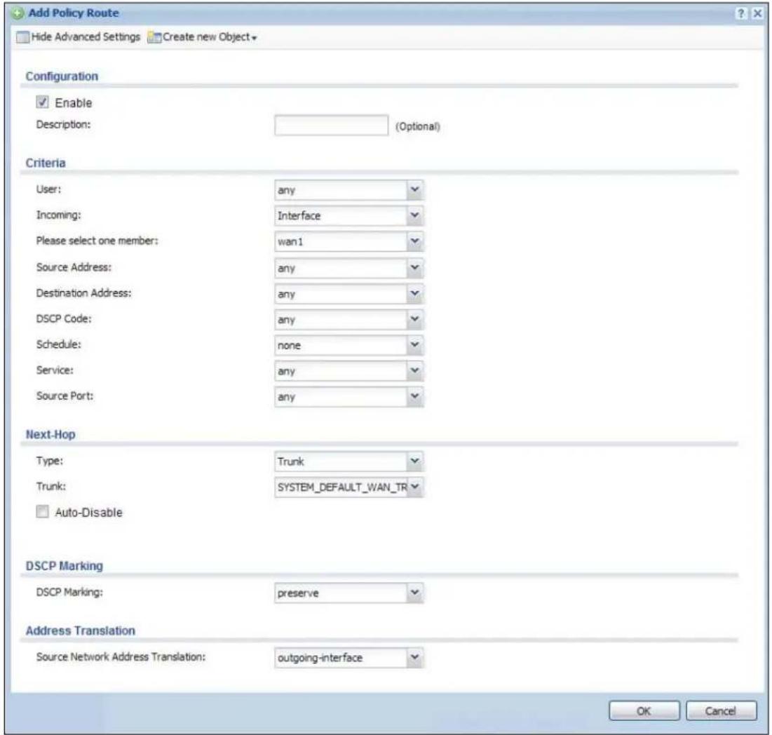
text_image
Add Policy Route Hide Advanced Settings Create new Object Configuration Enable Description: (Optional) Criteria User: any Incoming: Interface Please select one member: wan1 Source Address: any Destination Address: any DSCP Code: any Schedule: none Service: any Source Port: any Next-Hop Type: Trunk Trunk: SYSTEM_DEFAULT_WAN_TR Auto-Disable DSCP Marking DSCP Marking: preserve Address Translation Source Network Address Translation: outgoing-interface OK CancelThe following table describes the labels in this screen.
Table 74 Configuration > Network > Routing > Policy Route > Add/Edit
| LABEL DESCRIPTION | |
| Show / Hide Advanced Settings | Click this button to display a greater or lesser number of configuration fields. |
| Create new Object | Use this to configure any new settings objects that you need to use in this screen. |
| Configuration | |
| Enable Select this | to activate the policy. |
| Description | Enter a descriptive name of up to 31 printable ASCII characters for the policy. |
| Criteria | |
| User Select a user | name or user group from which the packets are sent. |
| Incoming | Select where the packets are coming from; any, an interface, or the UAG itself (Device). For an interface, you also need to select the individual interface. |
| LABEL | DESCRIPTION |
| Please select one member | This field displays only when you set Incoming to Interface. Select an interface from which the packets are sent. |
| Source Address Select a source IP address object from which the packets are sent. | |
| Destination Address | Select a destination IP address object to which the traffic is being sent. |
| DSCP Code | Select a DSCP code point value of incoming packets to which this policy route applies or select User Define to specify another DSCP code point. The lower the number the higher the priority with the exception of 0 which is usually given only best-effort treatment.any means all DSCP value or no DSCP marker.default means traffic with a DSCP value of 0. This is usually best effort trafficThe “af” choices stand for Assured Forwarding. The number following the “af” identifies one of four classes and one of three drop preferences. See Assured Forwarding (AF) PHB for DiffServ on page 175 for more details. |
| User-Defined DSCP Code | Use this field to specify a custom DSCP code point. |
| Schedule | Select a schedule to control when the policy route is active. none means the route is active at all times if enabled. |
| Service | Select a service or service group to identify the type of traffic to which this policy route applies. |
| Source Port | Select a service or service group to identify the source port of packets to which the policy route applies. |
| Next-Hop | |
| Type | Select Auto to have the UAG use the routing table to find a next-hop and forward the matched packets automatically.Select Gateway to route the matched packets to the next-hop router or switch you specified in the Gateway field. You have to set up the next-hop router or switch as a HOST address object first.Select VPN Tunnel to route the matched packets via the specified VPN tunnel.Select Trunk to route the matched packets through the interfaces in the trunk group based on the load balancing algorithm.Select Interface to route the matched packets through the specified outgoing interface to a gateway (which is connected to the interface). |
| Gateway | This field displays when you select Gateway in the Type field. Select a HOST address object. The gateway is an immediate neighbor of your UAG that will forward the packet to the destination. The gateway must be a router or switch on the same segment as your UAG's interface(s). |
| VPN Tunnel | This field displays when you select VPN Tunnel in the Type field. Select a VPN tunnel through which the packets are sent to the remote network that is connected to the UAG directly. |
| Trunk | This field displays when you select Trunk in the Type field. Select a trunk group to have the UAG send the packets via the interfaces in the group. |
| Interface | This field displays when you select Interface in the Type field. Select an interface to have the UAG send traffic that matches the policy route through the specified interface. |
| Auto-Disable | This field displays when you select Interface or Trunk in the Type field. Select this to have the UAG automatically disable this policy route when the next hop's connection is down. |
| DSCP Marking | |
| LABEL DESCRIPTION | |
| DSCP Marking | Set how the UAG handles the DSCP value of the outgoing packets that match this route.Select one of the pre-defined DSCP values to apply or selectUser Defineto specify another DSCP value. The "af" choices stand for Assured Forwarding. The number following the "af" identifies one of four classes and one of three drop preferences. SeeAssured Forwarding (AF) PHB for DiffServ on page 175for more details.Selectpreserveto have the UAG keep the packets' original DSCP value.Selectdefaultto have the UAG set the DSCP value of the packets to 0. |
| User-Defined DSCP Marking | Use this field to specify a custom DSCP value. |
| Address Translation | Use this section to configure NAT for the policy route. This section does not apply to policy routes that use a VPN tunnel as the next hop. |
| Source Network Address Translation | Selectnoneto not use NAT for the route.Selectoutgoing-interfaceto use the IP address of the outgoing interface as the source IP address of the packets that matches this route.To use SNAT for a virtual interface that is in the same WAN trunk as the physical interface to which the virtual interface is bound, the virtual interface and physical interface must be in different subnets.Otherwise, select a pre-defined address (group) to use as the source IP address(es) of the packets that match this route.UseCreate new Objectif you need to configure a new address (group) to use as the source IP address(es) of the packets that match this route. |
| OK | ClickOKto save your changes back to the UAG. |
| Cancel | ClickCancelto exit this screen without saving. |
12.3 IP Static Route Screen
Click Configuration > Network > Routing > Static Route to open the Static Route screen. This screen displays the configured static routes. Configure static routes to be able to propagate the routing information to other routers.
Figure 106 Configuration > Network > Routing > Static Route

text_image
Policy Route Static Route Configuration Add Edit RemoveDestination Subnet Mask Next-Hop Metric
Page 1 of 1 Show 50 items No data to displayThe following table describes the labels in this screen.
Table 75 Configuration > Network > Routing > Static Route
| LABEL DESCRIPTION | |
| Add Click this to create a new static route. | |
| Edit | Double-click an entry or select it and click Edit to open a screen where you can modify the entry's settings. |
| Remove | To remove an entry, select it and click Remove. The UAG confirms you want to remove it before doing so. |
| # This is the number of an individual static route. | |
| Destination This is the destination IP address. | |
| Subnet Mask This is the IP subnet mask. | |
| Next-Hop | This is the IP address of the next-hop gateway or the interface through which the traffic is routed. The gateway is a router or switch on the same segment as your UAG's interface(s). The gateway helps forward packets to their destinations. |
| Metric | This is the route's priority among the UAG's routes. The smaller the number, the higher priority the route has. |
12.3.1 Static Route Add/Edit Screen
Click Add or select a static route index number and click Edit. The screen shown next appears. Use this screen to configure the required information for a static route.
Figure 107 Configuration > Network > Routing > Static Route > Add
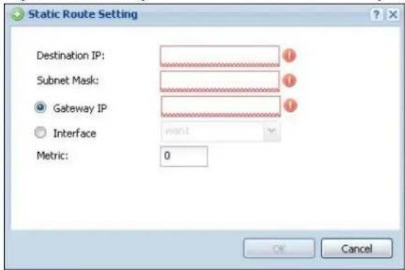
text_image
Static Route Setting Destination IP: Subnet Mask: Gateway IP Interface Metric: 0 OK CancelThe following table describes the labels in this screen.
Table 76 Configuration > Network > Routing > Static Route > Add/Edit
| LABEL DESCRIPTION | |
| Destination IP | This parameter specifies the IP network address of the final destination. Routing is always based on network number.If you need to specify a route to a single host, enter the specific IP address here and use a subnet mask of 255.255.255.255 (for IPv4) in the Subnet Mask field to force the network number to be identical to the host ID. |
| Subnet Mask Enter | the IP subnet mask here. |
| Gateway IP | Select the radio button and enter the IP address of the next-hop gateway. The gateway is a router or switch on the same segment as your UAG's interface(s). The gateway helps forward packets to their destinations. |
| Interface | Select the radio button and a predefined interface through which the traffic is sent. |
| Metric | Metric represents the “cost” of transmission for routing purposes. IP routing uses hop count as the measurement of cost, with a minimum of 1 for directly connected networks. Enter a number that approximates the cost for this link. The number need not be precise, but it must be 0~127. In practice, 2 or 3 is usually a good number. |
| OK | Click OK to save your changes back to the UAG. |
| Cancel | Click Cancel to exit this screen without saving. |
12.4 Policy Routing Technical Reference
Here is more detailed information about some of the features you can configure in policy routing.
NAT and SNAT
NAT (Network Address Translation - NAT, RFC 1631) is the translation of the IP address in a packet in one network to a different IP address in another network. Use SNAT (Source NAT) to change the source IP address in one network to a different IP address in another network.
Assured Forwarding (AF) PHB for DiffServ
Assured Forwarding (AF) behavior is defined in RFC 2597. The AF behavior group defines four AF classes. Inside each class, packets are given a high, medium or low drop precedence. The drop precedence determines the probability that routers in the network will drop packets when congestion occurs. If congestion occurs between classes, the traffic in the higher class (smaller numbered class) is generally given priority. Combining the classes and drop precedence produces the following twelve DSCP encodings from AF11 through AF43. The decimal equivalent is listed in brackets.
Table 77 Assured Forwarding (AF) Behavior Group
| CLASS 1 CLASS 2 CLASS 3 CLASS 4 | ||||
| Low Drop Precedence AF11 (10) | AF21 (18) | AF31 (26) | AF41 (34) | |
| Medium Drop Precedence | AF12 (12) | AF22 (20) | AF32 (28) | AF42 (36) |
| High Drop Precedence | AF13 (14) | AF23 (22) | AF33 (30) | AF43 (38) |
13.1 Zones Overview
Set up zones to configure network security and network policies in the UAG. A zone is a group of interfaces and/or VPN tunnels. The UAG uses zones instead of interfaces in many security and policy settings, such as firewall rules and remote management.
Zones cannot overlap. Each Ethernet interface, VLAN interface, bridge interface, PPPoE/PPTP interface and VPN tunnel can be assigned to at most one zone. Virtual interfaces are automatically assigned to the same zone as the interface on which they run.
Figure 108 Example: Zones

flowchart
graph TD
    subgraph VLAN1
        A["Computer"] --> B["Switch"]
        C["Computer"] --> B
        D["Computer"] --> B
        E["Computer"] --> B
    end
    subgraph VLAN2
        F["Computer"] --> G["Switch"]
        H["Computer"] --> G
        I["Computer"] --> G
        J["Computer"] --> G
        K["Computer"] --> G
    end
    subgraph Ethernet1
        L["Computer"] --> M["Switch"]
        N["Computer"] --> M
        O["Computer"] --> M
        P["Computer"] --> M
    end
    subgraph C
        Q["Computer"] --> R["Switch"]
        S["Computer"] --> R
        T["Computer"] --> R
    end
    subgraph WAN
        U["ISP 1"] --> V["Internet"]
        W["ISP 2"] --> V
    end
    style VLAN1 fill:#f9f,stroke:#333
    style VLAN2 fill:#f9f,stroke:#333
    style INTERNET1 fill:#ccf,stroke:#333
    style INTERNET2 fill:#ccf,stroke:#333
    style CMM1 fill:#ccf,stroke:#333
    style DMZ fill:#ccf,stroke:#333
    style WAN fill:#cfc,stroke:#333
13.1.1 What You Can Do in this Chapter
Use the Zone screens (see Section 13.2 on page 177) to manage the UAG's zones.
13.1.2 What You Need to Know
Effects of Zones on Different Types of Traffic
Zones effectively divide traffic into three types--intra-zone traffic, inter-zone traffic, and extra-zone traffic--which are affected differently by zone-based security and policy settings.
Intra-zone Traffic
- Intra-zone traffic is traffic between interfaces or VPN tunnels in the same zone. For example, in Figure 108 on page 176, traffic between VLAN 2 and the Ethernet is intra-zone traffic.
- You can set up firewall rules to control intra-zone traffic (for example, DMZ-to-DMZ), but many other types of zone-based security and policy settings do not affect intra-zone traffic.
Inter-zone Traffic
Inter-zone traffic is traffic between interfaces or VPN tunnels in different zones. For example, in Figure 108 on page 176, traffic between VLAN 1 and the Internet is inter-zone traffic. This is the normal case when zone-based security and policy settings apply.
Extra-zone Traffic
- Extra-zone traffic is traffic to or from any interface or VPN tunnel that is not assigned to a zone. For example, in Figure 108 on page 176, traffic to or from computer C is extra-zone traffic.
- Some zone-based security and policy settings may apply to extra-zone traffic, especially if you can set the zone attribute in them to Any or All. See the specific feature for more information.
13.2 The Zone Screen
The Zone screen provides a summary of all zones. In addition, this screen allows you to add, edit, and remove zones. To access this screen, click Configuration > Network > Zone.
Figure 109 Configuration > Network > Zone

text_image
Zone User Configuration Add Edit Remove Object ReferenceName Member
Page 1 of 1 Show 50 items No data to display System Default Edit Object ReferenceName Member
1 LAN1 Ian1 2 LAN2 Ian2 3 WAN wan1,wan1_ppp,wan2,wan2_ppp 4 DMZ dmz 5 IPSec_VPN Page 1 of 1 Show 50 items Displaying 1 - 5 of 5The following table describes the labels in this screen.
Table 78 Configuration > Network > Zone
| LABEL DESCRIPTION | |
| User Configuration / System Default | The UAG comes with pre-configured System Default zones that you cannot delete. You can create your own User Configuration zones |
| Add Click this to create a new, user-configured zone. | |
| Edit | Double-click an entry or select it and click Edit to open a screen where you can modify the entry's settings. |
| Remove | To remove a user-configured trunk, select it and click Remove. The UAG confirms you want to remove it before doing so. |
| Object References | Select an entry and click Object References to open a screen that shows which settings use the entry. See Section 10.3.2 on page 129 for an example. |
| # This field is a sequential value, and it is not associated with any interface. | |
| Name This field displays the name of the zone. | |
| Member This field displays the names of the interfaces that belong to each zone. | |
13.2.1 Zone Add/Edit
The Zone Edit screen allows you to add or edit a zone. To access this screen, go to the Zone screen (see Section 13.2 on page 177), and click the Add icon or select an entry and click the Edit icon.
Figure 110 Network > Zone > Add
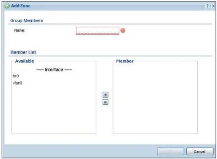
text_image
Add Zone Group Members Name: Member List Available === Interface === br0 vlan0 Member CancelThe following table describes the labels in this screen.
Table 79 Network > Zone > Add/Edit
| LABEL DESCRIPTION | |
| Name For a system | default zone, the name is read only.For a user-configured zone, type the name used to refer to the zone. You may use 1-31 alphanumeric characters, underscores ( ), or dashes (-), but the first character cannot be a number. This value is case-sensitive. |
| Member List | Availablelists the interfaces and VPN tunnels that do not belong to any zone. Select the interfaces and VPN tunnels that you want to add to the zone you are editing, and click the right arrow button to add them.Memberlists the interfaces and VPN tunnels that belong to the zone. Select any interfaces that you want to remove from the zone, and click the left arrow button to remove them. |
| OK | Click OKto save your customized settings and exit this screen. |
| Cancel | Click Cancelto exit this screen without saving. |
14.1 DDNS Overview
Dynamic DNS (DDNS) services let you use a domain name with a dynamic IP address.
14.1.1 What You Can Do in this Chapter
- Use the DDNS screen (see Section 14.2 on page 181) to view a list of the configured DDNS domain names and their details.
- Use the DDNS Add/ Edit screen (see Section 14.2.1 on page 182) to add a domain name to the UAG or to edit the configuration of an existing domain name.
14.1.2 What You Need to Know
DNS maps a domain name to a corresponding IP address and vice versa. Similarly, dynamic DNS maps a domain name to a dynamic IP address. As a result, anyone can use the domain name to contact you (in NetMeeting, CU-SeeMe, etc.) or to access your FTP server or Web site, regardless of the current IP address.
Note: You must have a public WAN IP address to use Dynamic DNS.
You must set up a dynamic DNS account with a supported DNS service provider before you can use Dynamic DNS services with the UAG. When registration is complete, the DNS service provider gives you a password or key. At the time of writing, the UAG supports the following DNS service providers. See the listed websites for details about the DNS services offered by each.
Table 80 DDNS Service Providers
| PROVIDER SERVICE TYPES SUPPORTED WEBSITE | |||
| DynDNS Dynamic DNS, Static DNS, and Custom DNS www.dyndns.com | |||
| Dynu | Basic, Premium www.dynu.com | ||
| No-IP | No-IP www.no-ip.com | ||
| Peanut Hull Peanut Hull www.oray.cn | |||
| 3322 3322 Dynamic DNS, 3322 Static DNS www.3322.org | |||
Note: Record your DDNS account's user name, password, and domain name to use to configure the UAG.
After, you configure the UAG, it automatically sends updated IP addresses to the DDNS service provider, which helps redirect traffic accordingly.
14.2 The DDNS Screen
The DDNS screen provides a summary of all DDNS domain names and their configuration. In addition, this screen allows you to add new domain names, edit the configuration for existing domain names, and delete domain names. Click Configuration > Network > DDNS to open the following screen.
Figure 111 Configuration > Network > DDNS

text_image
Profile Profile Summary Add Edit Remove Activate InactivatsStatus Profile Name DDNS Type Domain Name Primary Interface/P Backup Interface/P
1 Example DynDNS example wan1/from interface none Page 1 of 1 Show 50 items Displaying 1 - 1 of 1 Apply ResetThe following table describes the labels in this screen.
Table 81 Configuration > Network > DDNS
| LABEL DESCRIPTION | |
| Add Click this to create a new entry. | |
| Edit | Double-click an entry or select it and click Edit to open a screen where you can modify the entry's settings. |
| Remove | To remove an entry, select it and click Remove. The UAG confirms you want to remove it before doing so. |
| Activate | To turn on an entry, select it and click Activate. |
| Inactivate | To turn off an entry, select it and click Inactivate. |
| # This is the number of an individual DDNS profile. | |
| Status This icon is lit when the entry is active and dimmed when the entry is inactive. | |
| Profile Name This field displays the descriptive profile name for this entry. | |
| DDNS Type This field displays which DDNS service you are using. | |
| Domain Name This field displays each domain name the UAG can route. | |
| Primary Interface/IP | This field displays the interface to use for updating the IP address mapped to the domain name followed by how the UAG determines the IP address for the domain name.from interface - The IP address comes from the specified interface.auto detected -The DDNS server checks the source IP address of the packets from the UAG for the IP address to use for the domain name.custom - The IP address is static. |
| Backup Interface/IP | This field displays the alternate interface to use for updating the IP address mapped to the domain name followed by how the UAG determines the IP address for the domain name. The UAG uses the backup interface and IP address when the primary interface is disabled, its link is down or its connectivity check fails.from interface - The IP address comes from the specified interface.auto detected -The DDNS server checks the source IP address of the packets from the UAG for the IP address to use for the domain name.custom - The IP address is static. |
Table 81 Configuration > Network > DDNS (continued)
| LABEL DESCRIPTION |
| Apply Click this button to save your changes to the UAG. |
| Reset Click this button to return the screen to its last-saved settings. |
14.2.1 The Dynamic DNS Add/Edit Screen
The DDNS Add/ Edit screen allows you to add a domain name to the UAG or to edit the configuration of an existing domain name. Click Configuration > Network > DDNS and then an Add or Edit icon to open this screen.
Figure 112 Configuration > Network > DDNS > Add

text_image
Add Profile Hide Advanced Settings General Settings Enable DDNS Profile Profile Name: DDNS Type: DynDNS DDNS Account Username: Password: Retype to Confirm: DDNS Settings Domain Name: Primary Binding Address Interface: wan1 IP Address: Interface Backup Binding Address Interface: none Enable Wildcard Mail Exchanger: (Optional) Backup Mail Exchanger CancelThe following table describes the labels in this screen.
Table 82 Configuration > Network > DDNS > Add/Edit
| LABEL DESCRIPTION | |
| Show Advanced Settings / Hide Advanced Settings | Click this button to display a greater or lesser number of configuration fields. |
| Enable DDNS Profile | Select this check box to use this DDNS entry. |
| Profile Name | When you are adding a DDNS entry, type a descriptive name for this DDNS entry in the UAG. You may use 1-31 alphanumeric characters, underscores( ), or dashes (-), but the first character cannot be a number. This value is case-sensitive.This field is read-only when you are editing an entry. |
| DDNS Type Select | the type of DDNS service you are using. |
| DDNS Account | |
| Username | Type the user name used when you registered your domain name. You can use up to 31 alphanumeric characters and the underscore. Spaces are not allowed.For a Dynu DDNS entry, this user name is the one you use for logging into the service, not the name recorded in your personal information in the Dynu website. |
| Password | Type the password provided by the DDNS provider. You can use up to 64 alphanumeric characters and the underscore. Spaces are not allowed. |
| Retype to Confirm | Retype your new password for confirmation. |
| DDNS Settings | |
| Domain name Type | the domain name you registered. You can use up to 255 characters. |
| Primary Binding Address | Use these fields to set how the UAG determines the IP address that is mapped to your domain name in the DDNS server. The UAG uses the Backup Binding Address if the interface specified by these settings is not available. |
| Interface | Select the interface to use for updating the IP address mapped to the domain name. Select any to let the domain name be used with any interface. |
| IP Address The | options available in this field vary by DDNS provider.Interface -The UAG uses the IP address of the specified interface. This option appears when you select a specific interface in the Primary Binding Address Interface field.Auto - If the interface has a dynamic IP address, the DDNS server checks the source IP address of the packets from the UAG for the IP address to use for the domain name. You may want to use this if there are one or more NAT routers between the UAG and the DDNS server.Note: The UAG may not determine the proper IP address if there is an HTTP proxy server between the UAG and the DDNS server.Custom - If you have a static IP address, you can select this to use it for the domain name. The UAG still sends the static IP address to the DDNS server. |
| Custom IP | This field is only available when the IP Address is Custom. Type the IP address to use for the domain name. |
| Backup Binding Address | Use these fields to set an alternate interface to map the domain name to when the interface specified by the Primary Binding Interface settings is not available. |
| Interface | Select the interface to use for updating the IP address mapped to the domain name. Select any to let the domain name be used with any interface. Select None to not use a backup address. |
| IP Address The | options available in this field vary by DDNS provider.Interface-The UAG uses the IP address of the specified interface. This option appears when you select a specific interface in the Backup Binding Address Interface field.Auto-The DDNS server checks the source IP address of the packets from the UAG for the IP address to use for the domain name. You may want to use this if there are one or more NAT routers between the UAG and the DDNS server.Note: The UAG may not determine the proper IP address if there is an HTTP proxy server between the UAG and the DDNS server.Custom- If you have a static IP address, you can select this to use it for the domain name. The UAG still sends the static IP address to the DDNS server. |
| Custom IP | This field is only available when the IP Address is Custom. Type the IP address to use for the domain name. |
| Enable Wildcard This | option is only available with a DynDNS account.Enable the wildcard feature to alias subdomains to be aliased to the same IP address as your (dynamic) domain name. This feature is useful if you want to be able to use, for example, www.yourhost.dyndns.org and still reach your hostname. |
| Mail Exchanger This | option is only available with a DynDNS account.DynDNS can route e-mail for your domain name to a mail server (called a mail exchanger). For example, DynDNS routes e-mail for john-doe@yourhost.dyndns.org to the host record specified as the mail exchanger.If you are using this service, type the host record of your mail server here. Otherwise leave the field blank.See www.dyndns.org for more information about mail exchangers. |
| Backup Mail Exchanger | This option is only available with a DynDNS account.Select this check box if you are using DynDNS's backup service for e-mail. With this service, DynDNS holds onto your e-mail if your mail server is not available. Once your mail server is available again, the DynDNS server delivers the mail to you. See www.dyndns.org for more information about this service. |
| OK | Click OK to save your changes back to the UAG. |
| Cancel | Click Cancel to exit this screen without saving. |
15.1 NAT Overview
NAT (Network Address Translation - NAT, RFC 1631) is the translation of the IP address of a host in a packet. For example, the source address of an outgoing packet, used within one network is changed to a different IP address known within another network. Use Network Address Translation (NAT) to make computers on a private network behind the UAG available outside the private network. If the UAG has only one public IP address, you can make the computers in the private network available by using ports to forward packets to the appropriate private IP address.
Suppose you want to assign ports 21-25 to one FTP, Telnet and SMTP server (A in the example), port 80 to another (B in the example) and assign a default server IP address of 172.16.0.35 to a third (C in the example). You assign the LAN IP addresses and the ISP assigns the WAN IP address. The NAT network appears as a single host on the Internet.
Figure 113 Multiple Servers Behind NAT Example
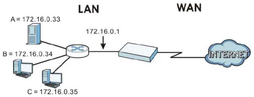
flowchart
graph LR
    A["Server"] --> B["Router"]
    C["Server"] --> B
    D["Server"] --> B
    B --> E["172.16.0.1"]
    B --> F["172.16.0.34"]
    B --> G["172.16.0.35"]
    H["A = 172.16.0.33"] --> B
    I["B = 172.16.0.34"] --> B
    J["C = 172.16.0.35"] --> B
    K["INTERNET"] --> L["Router"]
15.1.1 What You Can Do in this Chapter
Use the NAT screens (see Section 15.2 on page 186) to view and manage the list of NAT rules and see their configuration details. You can also create new NAT rules and edit or delete existing ones.
15.1.2 What You Need to Know
NAT is also known as virtual server, port forwarding, or port translation.
Finding Out More
• See Section 15.3 on page 190 for technical background information related to these screens.
15.2 The NAT Screen
The NAT summary screen provides a summary of all NAT rules and their configuration. In addition, this screen allows you to create new NAT rules and edit and delete existing NAT rules. To access this screen, login to the Web Configurator and click Configuration > Network > NAT. The following screen appears, providing a summary of the existing NAT rules.
Figure 114 Configuration > Network > NAT
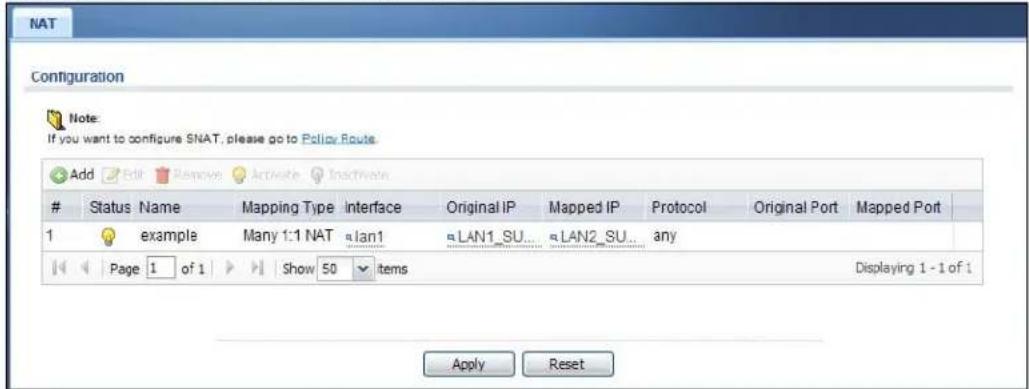
text_image
NAT Configuration Note: If you want to configure SNAT, please go to Policy Route Add Edit Remove Activate InactivateStatus Name Mapping Type Interface Original IP Mapped IP Protocol Original Port Mapped Port
1 example Many 1:1 NAT lan1 LAN1_SU... LAN2_SU... any Page 1 of 1 Show 50 items Displaying 1 - 1 of 1 Apply ResetThe following table describes the labels in this screen.
Table 83 Configuration > Network > NAT
| LABEL DESCRIPTION | |
| Add Click this to create a new entry. | |
| Edit | Double-click an entry or select it and click Edit to open a screen where you can modify the entry's settings. |
| Remove | To remove an entry, select it and click Remove. The UAG confirms you want to remove it before doing so. |
| Activate | To turn on an entry, select it and click Activate. |
| Inactivate | To turn off an entry, select it and click Inactivate. |
| # This field is a sequential value, and it is not associated with a specific entry. | |
| Status This icon is lit when the entry is active and dimmed when the entry is inactive. | |
| Name This field displays the name of the entry. | |
| Mapping Type | This field displays what kind of NAT this entry performs: Virtual Server, 1:1 NAT, or Many 1:1 NAT. |
| Interface | This field displays the interface on which packets for the NAT entry are received. |
| Original IP | This field displays the original destination IP address (or address object) of traffic that matches this NAT entry. It displays any if there is no restriction on the original destination IP address. |
| Mapped IP This field displays the new destination IP address for the packet. | |
| Protocol | This field displays the service used by the packets for this NAT entry. It displays any if there is no restriction on the services. |
| Original Port | This field displays the original destination port(s) of packets for the NAT entry. This field is blank if there is no restriction on the original destination port. |
| Mapped Port | This field displays the new destination port(s) for the packet. This field is blank if there is no restriction on the original destination port. |
Table 83 Configuration > Network > NAT (continued)
| LABEL DESCRIPTION |
| Apply Click this button to save your changes to the UAG. |
| Reset Click this button to return the screen to its last-saved settings. |
15.2.1 The NAT Add/Edit Screen
The NAT Add/ Edit screen lets you create new NAT rules and edit existing ones. To open this window, open the NAT summary screen. (See Section 15.2 on page 186.) Then, click on the Add icon or select an entry and click the Edit icon to open the following screen.
Figure 115 Configuration > Network > NAT > Add
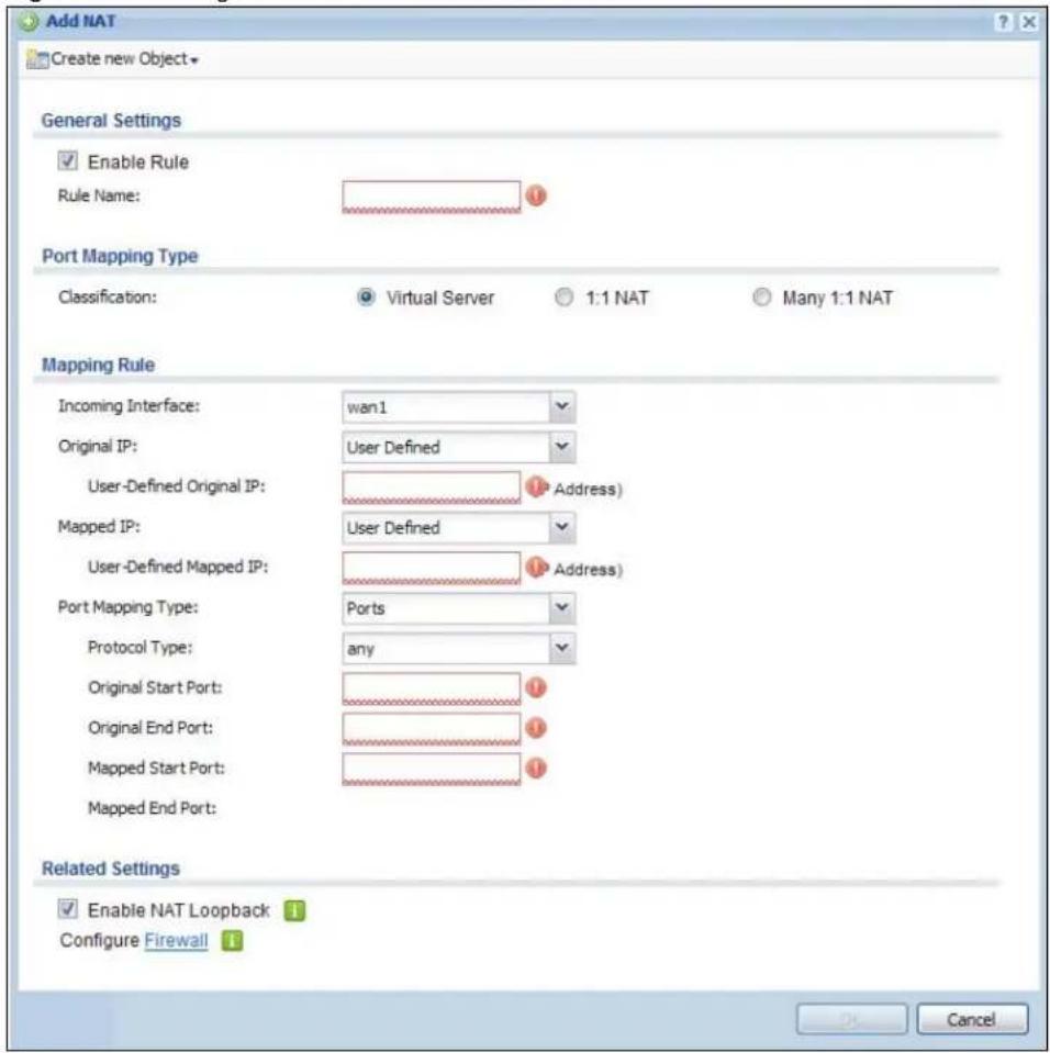
text_image
Add NAT Create new Object General Settings Enable Rule Rule Name: Port Mapping Type Classification: Virtual Server 1:1 NAT Many 1:1 NAT Mapping Rule Incoming Interface: wan1 Original IP: User Defined User-Defined Original IP: Address) Mapped IP: User Defined User-Defined Mapped IP: Address) Port Mapping Type: Ports Protocol Type: any Original Start Port: Original End Port: Mapped Start Port: Mapped End Port: Related Settings Enable NAT Loopback Configure Firewall OK CancelThe following table describes the labels in this screen.
Table 84 Configuration > Network > NAT > Add/Edit
| LABEL DESCRIPTION | |
| Create new Object | Use to configure any new settings objects that you need to use in this screen. |
| Enable Rule Use this | option to turn the NAT rule on or off. |
| Rule Name | Type in the name of the NAT rule. The name is used to refer to the NAT rule. You may use 1-31 alphanumeric characters, underscores( ), or dashes (-), but the first character cannot be a number. This value is case-sensitive. |
| Classification Select | what kind of NAT this rule is to perform.Virtual Server - This makes computers on a private network behind the UAG available to a public network outside the UAG (like the Internet).1:1 NAT - If the private network server will initiate sessions to the outside clients, select this to have the UAG translate the source IP address of the server's outgoing traffic to the same public IP address that the outside clients use to access the server.Many 1:1 NAT - If you have a range of private network servers that will initiate sessions to the outside clients and a range of public IP addresses, select this to have the UAG translate the source IP address of each server's outgoing traffic to the same one of the public IP addresses that the outside clients use to access the server. The private and public ranges must have the same number of IP addresses.One many 1:1 NAT rule works like multiple 1:1 NAT rules, but it eases configuration effort since you only create one rule. |
| Incoming Interface | Select the interface on which packets for the NAT rule must be received. It can be an Ethernet, VLAN, bridge, or PPPoE/PPTP interface. |
| Original IP Specify the destination IP address of the packets received by this NAT rule's specified incoming interface.any - Select this to use all of the incoming interface's IP addresses including dynamic addresses or those of any virtual interfaces built upon the selected incoming interface.User Defined - Select this to manually enter an IP address in the User Defined Original IP field. For example, you could enter a static public IP assigned by the ISP without having to create a virtual interface for it.Host address - select a host address object to use the IP address it specifies. The list also includes address objects based on interface IPs. So for example you could select an address object based on a WAN interface even if it has a dynamic IP address. | |
| User-Defined Original IP | This field is available if Original IP is User Defined. Type the destination IP address that this NAT rule supports. |
| Original IP Subnet/Range | This field displays for Many 1:1 NAT. Select the destination IP address subnet or IP address range that this NAT rule supports. The original and mapped IP address subnets or ranges must have the same number of IP addresses. |
| Mapped IP | Select to which translated destination IP address this NAT rule forwards packets.User Defined - this NAT rule supports a specific IP address, specified in the User-Defined Mapped IP field. |
| User-Defined Mapped IP | This field is available if Mapped IP is User Defined. Type the translated destination IP address that this NAT rule supports. |
| Mapped IP Subnet/Range | This field displays for Many 1:1 NAT. Select to which translated destination IP address subnet or IP address range this NAT rule forwards packets. The original and mapped IP address subnets or ranges must have the same number of IP addresses. |
| LABEL | DESCRIPTION |
| Port Mapping Type | Use the drop-down list box to select how many original destination ports this NAT rule supports for the selected destination IP address (Original IP). Choices are:Any- this NAT rule supports all the destination ports.Service- this NAT rule supports the destination port(s) used by the specified service(s).Port- this NAT rule supports one destination port.Ports- this NAT rule supports a range of destination ports. You might use a range of destination ports for unknown services or when one server supports more than one service.This field is read-only and displays any for Many 1:1 NAT. |
| Original Service | This field is available if Port Mapping Type is Service. Select the original service whose destination port(s) is supported by this NAT rule. |
| Mapped Service | This field is available if Port Mapping Type is Service. Select the translated service whose destination port(s) is supported if this NAT rule forwards the packet. |
| Protocol Type | This field is available if Port Mapping Type is Port or Ports. Select the protocol (TCP, UDP, or any) used by the service requesting the connection. |
| Original Port | This field is available if Port Mapping Type is Port. Enter the original destination port this NAT rule supports. |
| Mapped Port | This field is available if Port Mapping Type is Port. Enter the translated destination port if this NAT rule forwards the packet. |
| Original Start Port | This field is available if Port Mapping Type is Ports. Enter the beginning of the range of original destination ports this NAT rule supports. |
| Original End Port | This field is available if Port Mapping Type is Ports. Enter the end of the range of original destination ports this NAT rule supports. |
| Mapped Start Port | This field is available if Port Mapping Type is Ports. Enter the beginning of the range of translated destination ports if this NAT rule forwards the packet. |
| Mapped End Port | This field is available if Port Mapping Type is Ports. Enter the end of the range of translated destination ports if this NAT rule forwards the packet. The original port range and the mapped port range must be the same size. |
| Enable NAT Loopback | Enable NAT loopback to allow users connected to any interface (instead of just the specified Incoming Interface) to use the NAT rule's specified Original IP address to access the Mapped IP device. For users connected to the same interface as the Mapped IP device, the UAG uses that interface's IP address as the source address for the traffic it sends from the users to the Mapped IP device.For example, if you configure a NAT rule to forward traffic from the WAN to a LAN server, enabling NAT loopback allows users connected to other interfaces to also access the server. For LAN users, the UAG uses the LAN interface's IP address as the source address for the traffic it sends to the LAN server. See NAT Loopback on page 190 for more details.If you do not enable NAT loopback, this NAT rule only applies to packets received on the rule's specified incoming interface. |
| Firewall | By default the firewall blocks incoming connections from external addresses. After you configure your NAT rule settings, click the Firewall link to configure a firewall rule to allow the NAT rule's traffic to come in.The UAG checks NAT rules before it applies To-Device firewall rules, so To-Device firewall rules do not apply to traffic that is forwarded by NAT rules. The UAG still checks other firewall rules according to the source IP address and mapped IP address. |
| OK Click OK to save | your changes back to the UAG. |
| Cancel | Click Cancel to return to the NAT summary screen without creating the NAT rule (if it is new) or saving any changes (if it already exists). |
15.3 NAT Technical Reference
Here is more detailed information about NAT on the UAG.
NAT Loopback
Suppose an NAT 1:1 rule maps a public IP address to the private IP address of a LAN SMTP e-mail server to give WAN users access. NAT loopback allows other users to also use the rule's original IP to access the mail server.
For example, a LAN user's computer at IP address 172.16.0.89 queries a public DNS server to resolve the SMTP server's domain name (xxx.LAN-SMTP.com in this example) and gets the SMTP server's mapped public IP address of 1.1.1.1.
Figure 116 LAN Computer Queries a Public DNS Server
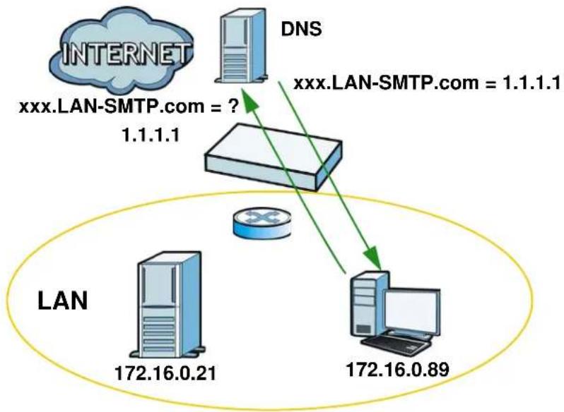
flowchart
graph TD
    A["INTERNET"] -->|xxx.LAN-SMTP.com = ? 1.1.1.1| B["DNS"]
    B -->|xxx.LAN-SMTP.com = 1.1.1.1| C["LAN"]
    C -->|172.16.0.21| D["Server"]
    C -->|172.16.0.89| E["Computer"]
The LAN user's computer then sends traffic to IP address 1.1.1.1. NAT loopback uses the IP address of the UAG's lan1 interface (172.16.0.1) as the source address of the traffic going from the LAN users to the LAN SMTP server.
Figure 117 LAN to LAN Traffic

flowchart
graph TD
    A["NAT"] -->|Source 172.16.0.1\nSMTP| B["LAN"]
    A -->|Source 172.16.0.89\nSMTP| C["Router"]
    B -->|172.16.0.21| C
    C -->|172.16.0.89| D["Computer"]
The LAN SMTP server replies to the UAG's LAN IP address and the UAG changes the source address to 1.1.1.1 before sending it to the LAN user. The return traffic's source matches the original destination address (1.1.1.1). If the SMTP server replied directly to the LAN user without the traffic going through NAT, the source would not match the original destination address which would cause the LAN user's computer to shut down the session.
Figure 118 LAN to LAN Return Traffic

flowchart
graph TD
    A["NAT"] -->|Source 172.16.0.21 SMTP| B["LAN"]
    A -->|Source 1.1.1 SMTP| C["Computer"]
    B -->|172.16.0.21| D["Router"]
    C -->|172.16.0.89| D
VPN 1-1 mapping allows an authenticated user in your network to access the Internet or an external server using a public IP address different from the one used by the UAG's WAN interface. With VPN 1-1 mapping, each user that logs into the UAG and matches a pre-configured mapping rule can obtain an individual public IP address. This helps especially when multiple users need to access different remote servers through separate VPN tunnels via the UAG. Each user can use a unique public IP address to transmit traffic through a separate VPN tunnel. The VPN connection will not be disconnected due to response packets with the same source IP address coming from remote servers in different VPN tunnels.
For example, users A and B are behind the UAG and both want to use a unique WAN IP address to access a public server through the UAG's WAN1 interface. After the user is authenticated by the UAG and meets the criteria in a VPN 1-1 mapping rule, the UAG applies the rule settings and assigns a public IP address to the user. Outgoing traffic from user A will then be sent through the WAN1 interface using the mapped public IP address 10.10.1.35. Outgoing traffic from user B will be sent through the WAN1 interface using the mapped public IP address 10.10.1.36.
Figure 119 VPN 1-1 Mapping Example

flowchart
graph TD
    A["Computer"] -->|10.10.1.35| WAN1["Switch"]
    B["Computer"] -->|10.10.1.36| WAN1
    WAN1 -->|10.10.1.35| INTERNET["Internet"]
    WAN1 -->|10.10.1.36| LAN["Server"]
    LAN -->|10.10.1.35| LAN
    LAN -->|10.10.1.36| LAN
    LAN -->|10.10.1.35| LAN
    LAN -->|10.10.1.36| LAN
    LAN -->|10.10.1.35| LAN
    LAN -->|10.10.1.36| LAN
16.1.1 What You Can Do in this Chapter
- Use the VPN 1-1 Mapping screens (see Section 16.2 on page 193) to enable and configure VPN 1-1 mapping to assign a public IP address to each of users that match the rules.
- Use the VPN 1-1 Mapping > Profile screen (see Section 16.3 on page 195) to configure a pool profile which defines the public IP address(es) that the UAG assigns to the matched users and the interface through which the user's traffic is forwarded.
16.1.2 What You Need to Know
VPN 1-1 Mapping, Firewall and Policy Route
With VPN 1-1 mapping, the relevant packet flow for traffic from the matched user is:
1 Firewall
2 Policy Route
3 VPN 1-1 Mapping
If you set a policy route to the same user/user group as a VPN 1-1 mapping rule, the UAG checks the policy routing rules first and forwards the traffic to a specified next-hop if matched. You need to make sure there is no firewall rule(s) blocking the traffic from the matched user or user group.
To make the example in Figure 119 on page 192 work, make sure you have the following settings. For traffic between lan1, lan2 or dmz and wan1:
- a from LAN1/LAN2/DMZ to WAN1 firewall rule (default) to allow any traffic from the user A/B from Ian1, Ian2 or dmz to wan1. Responses to this request are allowed automatically.
- a VPN 1-1 mapping rule to forward any traffic from the user A/B through the wan1 interface using a unique public IP address.
16.2 The VPN 1-1 Mapping General Screen
The VPN 1-1 Mapping summary screen provides a summary of all VPN 1-1 mapping rules and their configuration. In addition, this screen allows you to create new VPN 1-1 mapping rules and edit and delete existing VPN 1-1 mapping rules. To access this screen, login to the Web Configurator and click Configuration > Network > VPN 1-1 Mapping. The following screen appears, providing a summary of the existing VPN 1-1 mapping rules.
Figure 120 Configuration > Network > VPN 1-1 Mapping
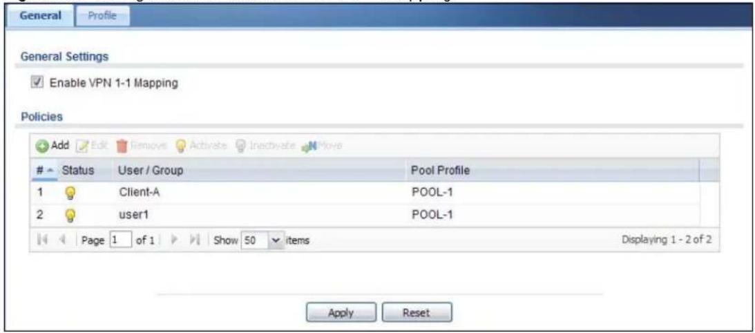
text_image
General Profile General Settings Enable VPN 1-1 Mapping Policies Add Edit Remove Activate Inactivate MoveStatus User / Group Pool Profile
1 Client-A POOL-1 2 user1 POOL-1 Page 1 of 1 Show 50 items Displaying 1 - 2 of 2 Apply ResetThe following table describes the labels in this screen.
Table 85 Configuration > Network > VPN 1-1 Mapping
| LABEL DESCRIPTION | |
| Enable VPN 1-1 Mapping | Select this option to enable VPN 1-1 mapping on the UAG. |
| Add Click this to create a new entry. | |
| Edit | Double-click an entry or select it and click Edit to open a screen where you can modify the entry's settings. |
| Remove | To remove an entry, select it and click Remove. The UAG confirms you want to remove it before doing so. |
| Activate | To turn on an entry, select it and click Activate. |
| Inactivate | To turn off an entry, select it and click Inactivate. |
| Move | To change a rule's position in the numbered list, select the rule and click Move to display a field to type a number for where you want to put that rule and press [ENTER] to move the rule to the number that you typed.The ordering of your rules is important as they are applied in order of their numbering. |
| # This field is a sequential value, and it is not associated with a specific entry. | |
| Status This icon is lit when the entry is active and dimmed when the entry is inactive. | |
| User / Group | This field displays the name of the user or user group object to which this rule is applied. |
| Pool Profile This field displays the name of the pool profile used by this rule. | |
| Apply Click this button to save your changes to the UAG. | |
| Reset Click this button to return the screen to its last-saved settings. | |
16.2.1 The VPN 1-1 Mapping Add/Edit Screen
Click Network > VPN 1-1 Mapping to open the VPN 1-1 Mapping > General screen. Then click the Add icon or select an entry and click the Edit icon to open the VPN 1-1 Mapping Add/ Edit Policy screen where you can configure the rule.
Figure 121 Network > VPN 1-1 Mapping > Add

text_image
Add Policy Create new Object Configuration Enable Policy User / Group User: any Pool Profile Selectable Pool Profiles === Object === POOL-1 Selected Pool Profiles OK CancelThe following table describes the labels in this screen.
Table 86 Network > VPN 1-1 Mapping > Add/Edit
| LABEL DESCRIPTION | |
| Create New Object | Click this button to create any new user/group objects that you need to use in this screen. |
| Enable Policy Use | this option to turn the VPN 1-1 mapping rule on or off. |
| User/Group | Use the drop-down list box to select the individual or group for which you want to use this rule.Selectanyto have the mapping rule apply to all of the traffic that the UAG receives from any user. |
| Pool Profile | The Selectable Pool Profileslist displays the name(s) of the pool profile(s) you can select for this mapping rule.To associate a pool profile to this mapping rule, you can double-click a single entry to move it or use the [Shift] or [Ctrl] key to select multiple entries and click the right arrow button to add to the Selected Pool Profileslist. To remove a pool profile, select the name(s) in the Selected Pool Profileslist and click the left arrow button.You can also use the up or down arrow button to change the order of members in the Selected Pool Profileslist. |
| OK | Click OKto save your changes back to the UAG. |
| Cancel | Click Cancelto exit this screen without saving. |
16.3 The VPN 1-1 Mapping Profile Screen
The VPN 1-1 Mapping Profile summary screen provides a summary of all pool profiles for VPN 1-1 mapping and their configuration. In addition, this screen allows you to create new pool profiles and edit and delete existing profiles. A pool profile defines the public IP address(es) that the UAG assigns to the matched users and the interface through which the user's traffic is forwarded. To access this screen, login to the Web Configurator and click Configuration > Network > VPN 1-1 Mapping > Profile. The following screen appears, providing a summary of the existing IP address pool profiles.
Figure 122 Configuration > Network > VPN 1-1 Mapping > Profile

text_image
General Profile Policies Add Edit Remove Object ReferencesName Address Interface
1 POOL-1 WAN-1_Subnet wan1 Page 1 of 1 Show 50 items Displaying 1 - 1 of 1 Apply ResetThe following table describes the labels in this screen.
Table 87 Configuration > Network > VPN 1-1 Mapping > Profile
| LABEL DESCRIPTION | |
| Add Click this to add an entry to the table.If you click Add without selecting an entry in advance then the new entry appears as the first entry. | |
| Edit | Double-click an entry or select it and click Edit to be able to modify the entry's settings. |
| Remove | To remove an entry, select it and click Remove. The UAG confirms you want to remove it before doing so. |
| Object Reference | Select an entry and click Object Reference to open a screen that shows which settings use the entry. See Section 10.3.2 on page 129 for an example. |
| # This field is a sequential value, and it is not associated with a specific entry. | |
| Name | This field displays a descriptive name for the profile. Enter a descriptive name to identify the profile. |
| Address | This field displays the name of the IP address object the profile is set to use. Select an address object that presents the IP address(es), which can be assigned to the matched users by the UAG.Note: You cannot select an address group object at the time of writing.Note: It's recommended that the IP addresses of the selected address object and the WAN interface are in the same subnet so that the UAG can receive response packets from the remote node. |
| Interface | This field displays the name of the interface the profile is set to use. Select the interface through which the UAG sends traffic from the matched users. |
| Apply Click this button to save your changes to the UAG. | |
| Reset Click this button to return the screen to its last-saved settings. | |
17.1 Overview
HTTP redirect forwards the client's HTTP request (except HTTP traffic destined for the UAG) to a web proxy server. In the following example, proxy server A is connected to the Ian2 interface in the LAN2 zone. When a client connected to the Ian1 interface in the LAN1 zone wants to open a web page, its HTTP request is redirected to proxy server A first. If proxy server A cannot find the web page in its cache, a policy route allows it to access the Internet to get them from a server. Proxy server A then forwards the response to the client.
Figure 123 HTTP Redirect Example
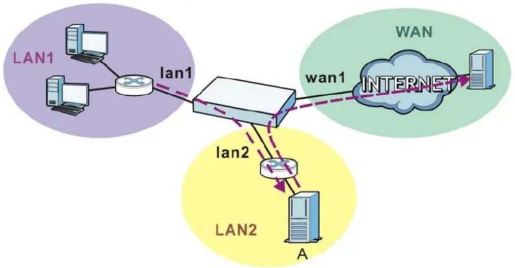
17.1.1 What You Can Do in this Chapter
Use the HTTP Redirect screens (see Section 17.2 on page 198) to display and edit the HTTP redirect rules.
17.1.2 What You Need to Know
Web Proxy Server
A proxy server helps client devices make indirect requests to access the Internet or outside network resources/services. A proxy server can act as a firewall or an ALG (application layer gateway) between the private network and the Internet or other networks. It also keeps hackers from knowing internal IP addresses.
A client connects to a web proxy server each time he/she wants to access the Internet. The web proxy provides caching service to allow quick access and reduce network usage. The proxy checks its local cache for the requested web resource first. If it is not found, the proxy gets it from the specified server and forwards the response to the client.
HTTP Redirect, Firewall and Policy Route
With HTTP redirect, the relevant packet flow for HTTP traffic is:
1 Firewall
2 HTTP Redirect
3 Policy Route
Even if you set a policy route to the same incoming interface and service as a HTTP redirect rule, the UAG checks the HTTP redirect rules first and forwards HTTP traffic to a proxy server if matched. You need to make sure there is no firewall rule(s) blocking the HTTP requests from the client to the proxy server.
You also need to manually configure a policy route to forward the HTTP traffic from the proxy server to the Internet. To make the example in Figure 123 on page 197 work, make sure you have the following settings.
For HTTP traffic between lan1 and lan2:
- a from LAN1 to LAN2 firewall rule to allow HTTP requests from Ian1 to Ian2. Responses to this request are allowed automatically.
- a HTTP redirect rule to forward HTTP traffic from Ian1 to proxy server A.
For HTTP traffic between lan2 and wan1:
- a from LAN2 to WAN firewall rule (default) to allow HTTP requests from lan2 to wan1. Responses to these requests are allowed automatically.
- a policy route to forward HTTP traffic from proxy server A to the Internet.
17.2 The HTTP Redirect Screen
To configure redirection of a HTTP request to a proxy server, click Configuration > Network > HTTP Redirect. This screen displays the summary of the HTTP redirect rules.
Note: You can configure up to one HTTP redirect rule for each (incoming) interface.
Figure 124 Configuration > Network > HTTP Redirect

text_image
HTTP Redirect Configuration Add Edit Remove Activate InactivateStatus Name Interface Proxy Server Port
1 example alan2 172.17.1.56 80 Page 1 of 1 Show 50 items Displaying 1 - 1 of 1 Apply ResetThe following table describes the labels in this screen.
Table 88 Configuration > Network > HTTP Redirect
| LABEL DESCRIPTION | |
| Add Click this to create a new entry. | |
| Edit | Double-click an entry or select it and click Edit to open a screen where you can modify the entry's settings. |
| Remove | To remove an entry, select it and click Remove. The UAG confirms you want to remove it before doing so. |
| Activate | To turn on an entry, select it and click Activate. |
| Inactivate | To turn off an entry, select it and click Inactivate. |
| # | This field is a sequential value, and it is not associated with a specific entry. |
| Status This icon is lit when the entry is active and dimmed when the entry is inactive. | |
| Name This is the descriptive name of a rule. | |
| Interface | This is the interface on which the request must be received. |
| Proxy Server This is the IP address of the proxy server. | |
| Port | This is the service port number used by the proxy server. |
| Apply Click Apply to save your changes back to the UAG. | |
| Reset | Click Reset to return the screen to its last-saved settings. |
17.2.1 The HTTP Redirect Add/Edit Screen
Click Network > HTTP Redirect to open the HTTP Redirect screen. Then click the Add icon or select an entry and click the Edit icon to open the screen where you can configure the rule.
Figure 125 Network > HTTP Redirect > Add/Edit

text_image
Add HTTP Redirect Enable Name: Interface: wan1 Proxy server: Port: OK CancelThe following table describes the labels in this screen.
Table 89 Network > HTTP Redirect > Add/Edit
| LABEL DESCRIPTION | |
| Enable Use this option to turn the HTTP redirect rule on or off. | |
| Name | Enter a name to identify this rule. You may use 1-31 alphanumeric characters, underscores( ), or dashes (-), but the first character cannot be a number. This value is case-sensitive. |
| Interface | Select the interface on which the HTTP request must be received for the UAG to forward it to the specified proxy server. |
| Proxy Server Enter | the IP address of the proxy server. |
| Port Enter the port | number that the proxy server uses. |
| OK | Click OK to save your changes back to the UAG. |
| Cancel | Click Cancel to exit this screen without saving. |
SMTP Redirect
18.1 Overview
SMTP redirect forwards the authenticated client's SMTP message to a SMTP server, that handles all outgoing e-mail messages. In the following example, SMTP server A is connected to the Ian2 interface in the LAN2 zone. When a client connected to the Ian1 interface in the LAN1 zone logs into the UAG and wants to send an e-mail, its SMTP message is redirected to SMTP server A. SMTP server A then sends it to a mail server, where the message will be delivered to the recipient.
The UAG forwards SMTP traffic using TCP port 25.
Figure 126 SMTP Redirect Example
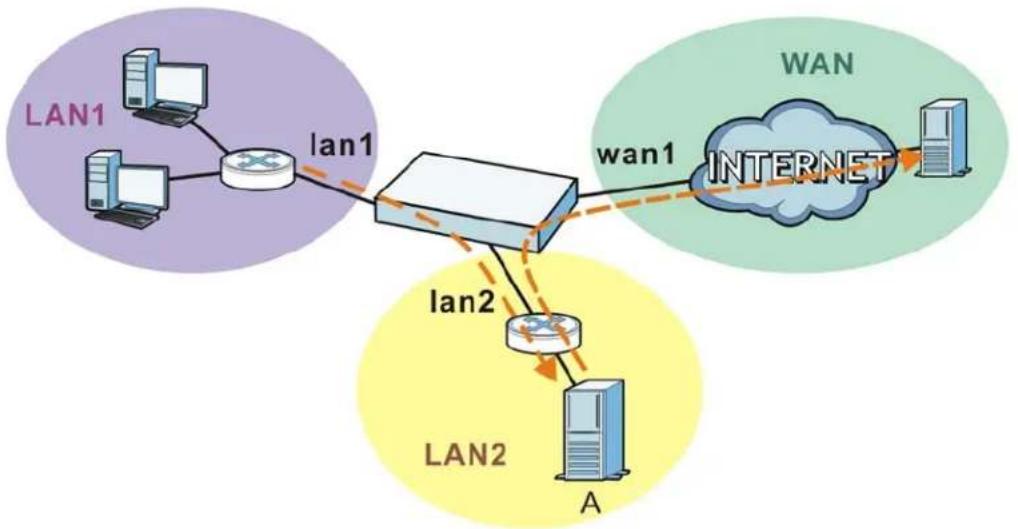
flowchart
graph TD
    subgraph LAN1
        A["Computer"] --> B["Switch"]
        C["Computer"] --> B
        B --> D["LAN1"]
    end
    subgraph LAN2
        E["Server"] --> F["Switch"]
        G["Server"] --> F
        F --> H["LAN2"]
    end
    subgraph WAN
        I["Cloud"] --> J["Server"]
    end
    subgraph Internet
        K["Internet"] --> L["Server"]
    end
18.1.1 What You Can Do in this Chapter
Use the SMTP Redirect screens (see Section 18.2 on page 202) to display and edit the SMTP redirect rules.
18.1.2 What You Need to Know
SMTP
Simple Mail Transfer Protocol (SMTP) is the Internet's message transport standard. It controls the sending of e-mail messages between servers. E-mail clients (also called e-mail applications) then use mail server protocols such as POP (Post Office Protocol) or IMAP (Internet Message Access Protocol) to retrieve e-mail. E-mail clients also generally use SMTP to send messages to a mail
server. The older POP2 requires SMTP for sending messages while the newer POP3 can be used with or without it. This is why many e-mail applications require you to specify both the SMTP server and the POP or IMAP server (even though they may actually be the same server).
SMTP Redirect, Firewall and Policy Route
With SMTP redirect, the relevant packet flow for SMTP traffic is:
1 Firewall
2 SMTP Redirect
3 Policy Route
Even if you set a policy route to the same incoming interface and service as a SMTP redirect rule, the UAG checks the SMTP redirect rules first and forwards SMTP traffic to a SMTP server if matched. You need to make sure there is no firewall rule(s) blocking the SMTP traffic from the client to the SMTP server.
You also need to manually configure a policy route to forward the SMTP traffic from the SMTP server to the Internet. To make the example in Figure 126 on page 201 work, make sure you have the following settings.
For SMTP traffic between lan1 and lan2:
- a from LAN1 to LAN2 firewall rule to allow SMTP messages from Ian1 to Ian2. Responses to this request are allowed automatically.
- a SMTP redirect rule to forward SMTP traffic from Ian1 to SMTP server A.
For SMTP traffic between lan2 and wan1:
- a from LAN2 to WAN firewall rule (default) to allow SMTP messages from lan2 to wan1. Responses to these requests are allowed automatically.
- a policy route to forward SMTP messages from SMTP server A to the Internet.
18.2 The SMTP Redirect Screen
To configure redirection of a SMTP message to a SMTP server, click Configuration > Network > SMTP Redirect. This screen displays the summary of the SMTP redirect rules.
Note: You can configure up to one SMTP redirect rule for each (incoming) interface.
Figure 127 Configuration > Network > SMTP Redirect

text_image
SMTP Redirect General Setting Enable SMTP Redirect SMTP Redirect Settings Add Edit Remove Activate Inactivate MoveStat... User/Group Interface Source Address SMTP Server
1 any slan1 any 172.17.0.99 Page 1 of 1 Show 50 items Displaying 1 - 1 of 1 Apply ResetThe following table describes the labels in this screen.
Table 90 Configuration > Network > SMTP Redirect
| LABEL DESCRIPTION | |
| Enable SMTP Redirect | Select this option to turn on the SMTP redirect feature on the UAG. |
| Add Click this to create a new entry. | |
| Edit | Double-click an entry or select it and click Edit to open a screen where you can modify the entry's settings. |
| Remove | To remove an entry, select it and click Remove. The UAG confirms you want to remove it before doing so. |
| Activate | To turn on an entry, select it and click Activate. |
| Inactivate | To turn off an entry, select it and click Inactivate. |
| Move | To change a rule's position in the numbered list, select the rule and click Move to display a field to type a number for where you want to put that rule and press [ENTER] to move the rule to the number that you typed.The ordering of your rules is important as they are applied in order of their numbering. |
| # This field is a sequential value, and it is not associated with a specific entry. | |
| Status This icon is lit when the entry is active and dimmed when the entry is inactive. | |
| User/Group | This is the user account or user group name to whose SMTP traffic this rule is applied. |
| Incoming Interface | This is the name of the interface on which the SMTP traffic must be received. |
| Source Address | This is the name of the source IP address object from which the SMTP traffic should be sent. If any displays, the rule is effective for every source. |
| SMTP Server | This is the IP address of the SMTP server to which the matched SMTP traffic is forwarded. |
| Apply Click Apply to save your changes back to the UAG. | |
| Reset | Click Reset to return the screen to its last-saved settings. |
18.2.1 The SMTP Redirect Add/Edit Screen
Click Network > SMTP Redirect to open the SMTP Redirect screen. Then click the Add icon or select an entry and click the Edit icon to open the screen where you can configure the rule.
Figure 128 Network > SMTP Redirect > Add/Edit
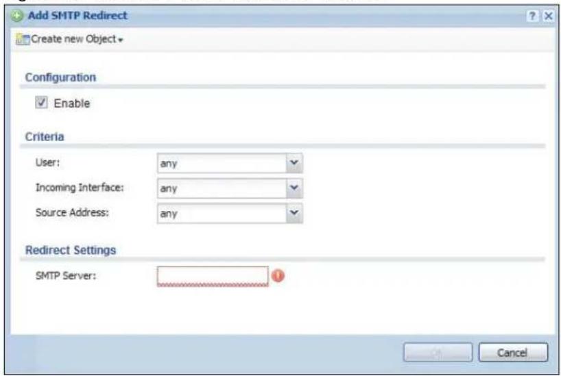
text_image
Add SMTP Redirect Create new Object Configuration Enable Criteria User: any Incoming Interface: any Source Address: any Redirect Settings SMTP Server: CancelThe following table describes the labels in this screen.
Table 91 Network > SMTP Redirect > Add/Edit
| LABEL DESCRIPTION | |
| Enable Use this option to turn the SMTP redirect rule on or off. | |
| User | Use the drop-down list box to select the individual user or user group for which you want to use this rule.Selectanyto have the SMTP redirect rule apply to all of the SMTP messages that the UAG receives from any user. |
| Incoming Interface | Select the interface on which the SMTP traffic must be received for the UAG to forward it to the specified SMTP server. |
| Source Address | Select the source address or address group for whom this rule applies. UseCreate new Objectif you need to configure a new one. Selectanyif the rule is effective for every source. |
| SMTP Server Enter the IP address of the SMTP server. | |
| OK | ClickOKto save your changes back to the UAG. |
| Cancel | ClickCancelto exit this screen without saving. |
19.1 ALG Overview
Application Layer Gateway (ALG) allows the following application to operate properly through the UAG's NAT.
- FTP - File Transfer Protocol - an Internet file transfer service.
The ALG feature is only needed for traffic that goes through the UAG's NAT.
19.1.1 What You Can Do in this Chapter
Use the ALG screen (Section 19.2 on page 206) to set up the FTP ALG settings.
19.1.2 What You Need to Know
Application Layer Gateway (ALG), NAT and Firewall
The UAG can function as an Application Layer Gateway (ALG) to allow certain NAT un-friendly applications to operate properly through the UAG's NAT and firewall. The UAG dynamically creates an implicit NAT session and firewall session for the application's traffic from the WAN to the LAN. The ALG on the UAG supports all of the UAG's NAT mapping types.
FTP ALG
The FTP ALG allows TCP packets with a specified port destination to pass through. If the FTP server is located on the LAN, you must also configure NAT (port forwarding) and firewall rules if you want to allow access to the server from the WAN.
ALG and Trunks
If you send your ALG-managed traffic through an interface trunk and all of the interfaces are set to active, you can configure routing policies to specify which interface the ALG-managed traffic uses.
You could also have a trunk with one interface set to active and a second interface set to passive. The UAG does not automatically change ALG-managed connections to the second (passive) interface when the active interface's connection goes down. When the active interface's connection fails, the client needs to re-initialize the connection through the second interface (that was set to passive) in order to have the connection go through the second interface.
19.1.3 Before You Begin
You must also configure the firewall and enable NAT in the UAG to allow sessions initiated from the WAN.
19.2 The ALG Screen
Click Configuration > Network > ALG to open the ALG screen. Use this screen to turn the ALG off or on, configure the port numbers to which it applies.
Figure 129 Configuration > Network > ALG
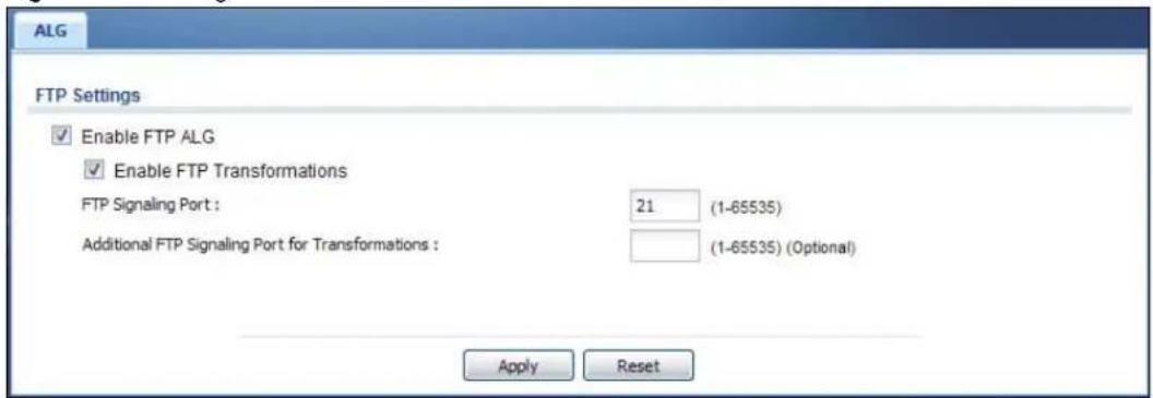
text_image
ALG FTP Settings ✓ Enable FTP ALG ✓ Enable FTP Transformations FTP Signaling Port : 21 (1-65535) Additional FTP Signaling Port for Transformations : (1-65535) (Optional) Apply ResetThe following table describes the labels in this screen.
Table 92 Configuration > Network > ALG
| LABEL DESCRIPTION | |
| Enable FTP ALG | Turn on the FTP ALG to detect FTP (File Transfer Program) traffic and help build FTP sessions through the UAG's NAT. |
| Enable FTP Transformations | Select this option to have the UAG modify IP addresses and port numbers embedded in the FTP data payload to match the UAG's NAT environment.Clear this option if you have an FTP device or server that will modify IP addresses and port numbers embedded in the FTP data payload to match the UAG's NAT environment. |
| FTP Signaling Port | If you are using a custom TCP port number (not 21) for FTP traffic, enter it here. |
| Additional FTP Signaling Port for Transformations | If you are also using FTP on an additional TCP port number, enter it here. |
| Apply | Click Apply to save your changes back to the UAG. |
| Reset | Click Reset to return the screen to its last-saved settings. |
20.1 Overview
The UAG supports both UPnP and NAT-PMP to permit networking devices to discover each other and connect seamlessly.
Universal Plug and Play (UPnP) is a distributed, open networking standard that uses TCP/IP for simple peer-to-peer network connectivity between devices. A UPnP device can dynamically join a network, obtain an IP address, convey its capabilities and learn about other devices on the network. In turn, a device can leave a network smoothly and automatically when it is no longer in use. A gateway that supports UPnP is called Internet Gateway Device (IGD). The standardized Device Control Protocol (DCP) is defined by the UPnP Forum for IGDs to configure port mapping automatically.
NAT Port Mapping Protocol (NAT-PMP), introduced by Apple and implemented in current Apple products, is used as an alternative NAT traversal solution to the UPnP IGD protocol. NAT-PMP runs over UDP port 5351. NAT-PMP is much simpler than UPnP IGD and mainly designed for small home networks. It allows a client behind a NAT router to retrieve the router's public IP address and port number and make them known to the peer device with which it wants to communicate. The client can automatically configure the NAT router to create a port mapping to allow the peer to contact it.
20.2 What You Need to Know
UPnP hardware is identified as an icon in the Network Connections folder (Windows XP). Each UPnP compatible device installed on your network will appear as a separate icon. Selecting the icon of a UPnP device will allow you to access the information and properties of that device.
20.2.1 NAT Traversal
UPnP NAT traversal automates the process of allowing an application to operate through NAT. UPnP network devices can automatically configure network addressing, announce their presence in the network to other UPnP devices and enable exchange of simple product and service descriptions. NAT traversal allows the following:
• Dynamic port mapping
- Learning public IP addresses
- Assigning lease times to mappings
Windows Messenger is an example of an application that supports NAT traversal and UPnP.
See the NAT chapter for more information on NAT.
20.2.2 Cautions with UPnP
The automated nature of NAT traversal applications in establishing their own services and opening firewall ports may present network security issues. Network information and configuration may also be obtained and modified by users in some network environments.
When a UPnP device joins a network, it announces its presence with a multicast message. For security reasons, the UAG allows multicast messages on the LAN only.
All UPnP-enabled devices may communicate freely with each other without additional configuration. Disable UPnP if this is not your intention.
20.3 UPnP Screen
Use this screen to enable UPnP and NAT-PMP on your UAG.
Click Configuration > Network > UPnP to display the screen shown next.
Figure 130 Configuration > Network > UPnP

text_image
UPnP General Setting ✓ Enable UPnP ✓ Enable NAT-PMP ✓ Allow UPnP or NAT-PMP to pass through Firewall Outgoing WAN Interface: ALL Support LAN List Available lan2 vlan0 Member lan1 Apply ResetThe following table describes the fields in this screen.
Table 93 Configuration > Network > UPnP
| LABEL DESCRIPTION | |
| Enable UPnP | Select this check box to activate UPnP on the UAG. Be aware that anyone could use a UPnP application to open the web configurator's login screen without entering the UAG's IP address (although you must still enter the password to access the web configurator). |
| Enable NAT-PMP | Select this check box to activate NAT-PMP on the UAG. Be aware that anyone could use a NAT-PMP application to open the web configurator's login screen without entering the UAG's IP address (although you must still enter the password to access the web configurator). |
| Allow UPnP or NAT-PMP to pass through Firewall | Select this check box to allow traffic from UPnP-enabled or NAT-PMP-enabled applications to bypass the firewall.Clear this check box to have the firewall block all UPnP or NAT-PMP application packets (for example, MSN packets). |
| Outgoing WAN Interface | Select through which WAN interface(s) you want to send out traffic from UPnP-enabled or NAT-PMP-enabled applications. If the WAN interface you select loses its connection, the UAG attempts to use the other WAN interface. If the other WAN interface also does not work, the UAG drops outgoing packets from UPnP-enabled or NAT-PMP-enabled applications. |
| Support LAN List | The Available list displays the name(s) of the internal interface(s) on which the UAG supports UPnP and/or NAT-PMP.To enable UPnP and/or NAT-PMP on an interface, you can double-click a single entry to move it or use the [Shift] or [Ctrl] key to select multiple entries and click the right arrow button to add to the Member list. To remove an interface, select the name(s) in the Member list and click the left arrow button. |
| Apply Click Apply to | save your changes back to the UAG. |
| Reset | Click Reset to return the screen to its last-saved settings. |
20.4 Technical Reference
The sections show examples of using UPnP.
20.4.1 Using UPnP in Windows XP Example
This section shows you how to use the UPnP feature in Windows XP. You must already have UPnP installed in Windows XP and UPnP activated on the UAG.
Make sure the computer is connected to a LAN port of the UAG. Turn on your computer and the UAG.
20.4.1.1 Auto-discover Your UPnP-enabled Network Device
1 Click start and Control Panel. Double-click Network Connections. An icon displays under Internet Gateway.
2 Right-click the icon and select Properties.
Figure 131 Network Connections
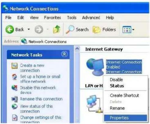
text_image
Network Connections File Edit View Favorites Tools Advanced Help Back Search Folders Address Network Connections Network Tasks Create a new connection Set up a home or small office network Disable this network device Rename this connection View status of this connection Change settings of this connection Internet Gateway Internet Connection Enabled Internet Connection LAN or H Disable Status Create Shortcut Delete Rename Properties3 In the Internet Connection Properties window, click Settings to see the port mappings there were automatically created.
Figure 132 Internet Connection Properties
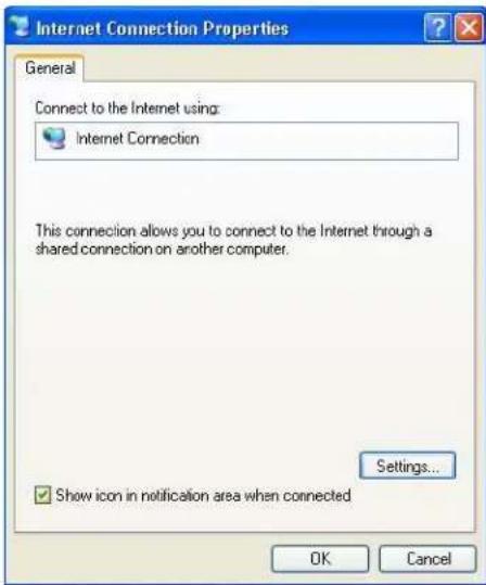
text_image
Internet Connection Properties General Connect to the Internet using: Internet Connection This connection allows you to connect to the Internet through a shared connection on another computer. Settings... ✓ Show icon in notification area when connected OK Cancel4 You may edit or delete the port mappings or click Add to manually add port mappings.
Figure 133 Internet Connection Properties: Advanced Settings
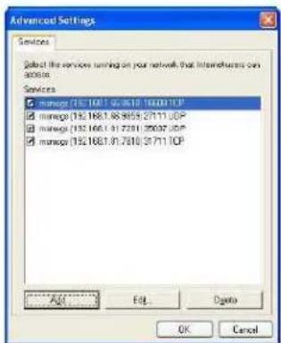
text_image
Advanced Settings Services Subd the services running on your network that interdevices can access. Services manage (192.1681.01.2610.16001TCP) manage (192.1681.06.3859.27111TCP) manage (192.1681.01.2701.29637TCP) manage (192.1681.01.2810.31711TCP) Add... Edit... Delete OK CancelFigure 134 Internet Connection Properties: Advanced Settings: Add
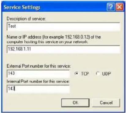
text_image
Service Settings Description of service: Test Name or IP address (for example 192.168.0.12) of the computer hosting this service on your network. 192.168.1.11 External Port number for this service: 143 Internal Port number for this service: 143 TCP UDP OK CancelNote: When the UPnP-enabled device is disconnected from your computer, all port mappings will be deleted automatically.
5 Select Show icon in notification area when connected option and click OK. An icon displays in the system tray.
Figure 135 System Tray Icon

text_image
Internet Connection is now connected Click here for more information...6 Double-click on the icon to display your current Internet connection status.
Figure 136 Internet Connection Status

text_image
Internet Connection Status General Internet Gateway Status: Connected Duration: 00:00:56 Speed: 100.0 Mbps Activity Internet Internet Gateway My Computer Packets Sent: 8 618 Received: 5.943 746 Properties Disable Close20.4.2 Web Configurator Easy Access
With UPnP, you can access the web-based configurator on the UAG without finding out the IP address of the UAG first. This comes helpful if you do not know the IP address of the UAG.
Follow the steps below to access the web configurator.
1 Click Start and then Control Panel.
2 Double-click Network Connections.
3 Select My Network Places under Other Places.
Figure 137 Network Connections
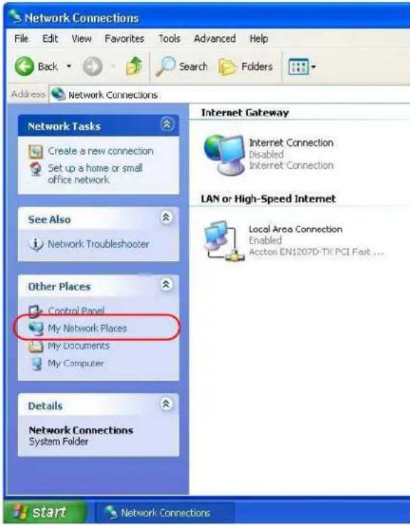
text_image
Network Connections File Edit View Favorites Tools Advanced Help Back Search Folders Address Network Connections Network Tasks Create a new connection Set up a home or small office network. See Also Network Troubleshooter Other Places Control Panel My Network Places My Documents My Computer Details Network Connections System Folder Internet Gateway Internet Connection Disabled Internet Connection LAN or High-Speed Internet Local Area Connection Enabled Accton EN1207D-TX PCI Fast ... start Network Connections4 An icon with the description for each UPnP-enabled device displays under Local Network.
5 Right-click on the icon for your UAG and select Invoke. The web configurator login screen displays.
Figure 138 Network Connections: My Network Places

text_image
My Network Places File Edit View Favorites Tools Help Back Search Folders Address My Network Places Network Tasks Add a network place View network connections Set up a home or small office network View workgroup computers Other Places Local Network ZyXEL Internet Sharing Gateway Invoke Create Shortcut Delete Rename Properties6 Right-click on the icon for your UAG and select Properties. A properties window displays with basic information about the UAG.
Figure 139 Network Connections: My Network Places: Properties: Example
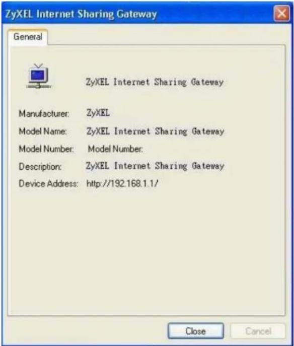
text_image
ZyXEL Internet Sharing Gateway General ZyXEL Internet Sharing Gateway Manufacturer: ZyXEL Model Name: ZyXEL Internet Sharing Gateway Model Number: Model Number: Description: ZyXEL Internet Sharing Gateway Device Address: http://192.168.1.1/ Close Cancel21.1 IP/MAC Binding Overview
IP address to MAC address binding helps ensure that only the intended devices get to use privileged IP addresses. The UAG uses DHCP to assign IP addresses and records to MAC address it assigned each IP address. The UAG then checks incoming connection attempts against this list. A user cannot manually assign another IP to his computer and use it to connect to the UAG.
Suppose you configure access privileges for IP address 172.16.1.27 and use static DHCP to assign it to Bob's computer's MAC address of 12:34:56:78:90:AB. IP/MAC binding drops traffic from any computer trying to use IP address 172.16.1.27 with another MAC address.
Figure 140 IP/MAC Binding Example
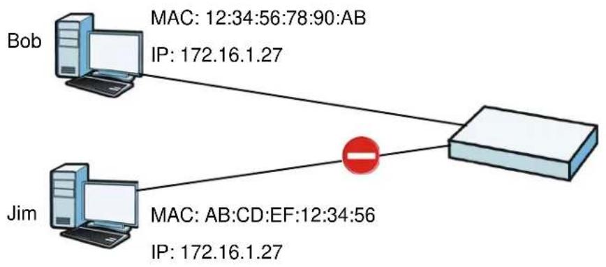
flowchart
graph TD
    Bob["Bob"] -->|MAC: 12:34:56:78:90:AB\nIP: 172.16.1.27| Router["Router"]
    Jim["Jim"] -->|MAC: AB:CD:EF:12:34:56\nIP: 172.16.1.27| Router
21.1.1 What You Can Do in this Chapter
- Use the Summary and Edit screens (Section 21.2 on page 215) to bind IP addresses to MAC addresses.
- Use the Exempt List screen (Section 21.3 on page 217) to configure ranges of IP addresses to which the UAG does not apply IP/MAC binding.
21.1.2 What You Need to Know
DHCP
IP/MAC address bindings are based on the UAG's dynamic and static DHCP entries.
Interfaces Used With IP/MAC Binding
IP/MAC address bindings are grouped by interface. You can use IP/MAC binding with Ethernet, bridge, VLAN interfaces. You can also enable or disable IP/MAC binding and logging in an interface's configuration screen.
21.2 IP/MAC Binding Summary
Click Configuration > Network > IP/ MAC Binding to open the IP/ MAC Binding Summary screen. This screen lists the total number of IP to MAC address bindings for devices connected to each supported interface.
Figure 141 Configuration > Network > IP/MAC Binding > Summary
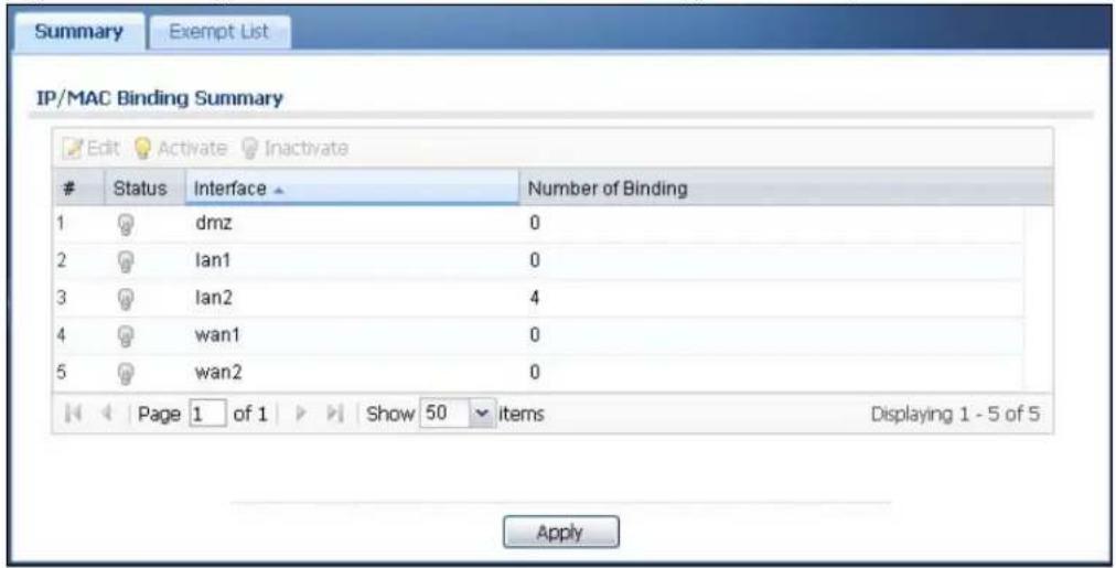
text_image
Summary Exempt List IP/MAC Binding Summary Edit Activate InactivateStatus Interface Number of Binding
1 dmz 0 2 Ian1 0 3 Ian2 4 4 wan1 0 5 wan2 0 Page 1 of 1 Show 50 items Displaying 1 - 5 of 5 ApplyThe following table describes the labels in this screen.
Table 94 Configuration > Network > IP/MAC Binding > Summary
| LABEL DESCRIPTION | |
| Edit | Double-click an entry or select it and click Edit to open a screen where you can modify the entry's settings. |
| Activate | To turn on an entry, select it and click Activate. |
| Inactivate | To turn off an entry, select it and click Inactivate. |
| # | This field is a sequential value, and it is not associated with a specific entry. |
| Status | This icon is lit when the entry is active and dimmed when the entry is inactive. |
| Interface | This is the name of an interface that supports IP/MAC binding. |
| Number of Binding | This field displays the interface's total number of IP/MAC bindings and IP addresses that the interface has assigned by DHCP. |
| Apply | Click Apply to save your changes back to the UAG. |
21.2.1 IP/MAC Binding Edit
Select an entry and click the Edit icon in the Configuration > Network > IP/ MAC Binding > Summary screen to open the screen. Use this screen to configure an interface's IP to MAC address binding settings.
Figure 142 Configuration > Network > IP/MAC Binding > Summary > Edit
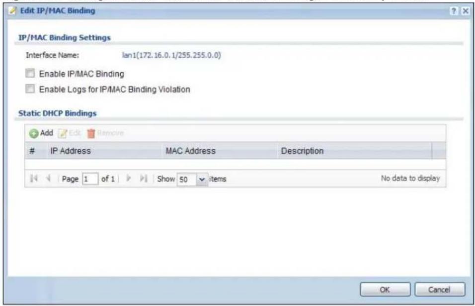
text_image
Edit IP/MAC Binding IP/MAC Binding Settings Interface Name: lan1(172.16.0.1/255.255.0.0) Enable IP/MAC Binding Enable Logs for IP/MAC Binding Violation Static DHCP Bindings Add Edit RemoveIP Address MAC Address Description
Page 1 of 1 Show 50 items No data to display OK CancelThe following table describes the labels in this screen.
Table 95 Configuration > Network > IP/MAC Binding > Summary > Edit
| LABEL DESCRIPTION | |
| IP/MAC Binding Settings | |
| Interface Name | This field displays the name of the interface within the UAG and the interface's IP address and subnet mask. |
| Enable IP/MAC Binding | Select this option to have this interface enforce links between specific IP addresses and specific MAC addresses. This stops anyone else from manually using a bound IP address on another device connected to this interface. Use this to make use only the intended users get to use specific IP addresses. |
| Enable Logs for IP/MAC Binding Violation | Select this option to have the UAG generate a log if a device connected to this interface attempts to use an IP address not assigned by the UAG. |
| Static DHCP Bindings | This table lists the bound IP and MAC addresses. The UAG checks this table when it assigns IP addresses. If the computer's MAC address is in the table, the UAG assigns the corresponding IP address. You can also access this table from the interface's edit screen. |
| Add Click this to create a new entry. | |
| Edit | Double-click an entry or select it and click Edit to open a screen where you can modify the entry's settings. |
| Remove | To remove an entry, select it and click Remove. The UAG confirms you want to remove it before doing so. |
| # This is the index | number of the static DHCP entry. |
| IP Address | This is the IP address that the UAG assigns to a device with the entry's MAC address. |
| MAC Address | This is the MAC address of the device to which the UAG assigns the entry's IP address. |
| Description This help | ps identify the entry. |
| OK | Click OK to save your changes back to the UAG. |
| Cancel | Click Cancel to exit this screen without saving. |
21.2.2 Static DHCP Add/Edit
In the Configuration > Network > IP/ MAC Binding > Summary > Edit screen, click the Add icon or select an entry and click the Edit icon to open the following screen. Use this screen to configure an interface's IP to MAC address binding settings.
Figure 143 Configuration > Network > IP/MAC Binding > Summary > Edit > Add
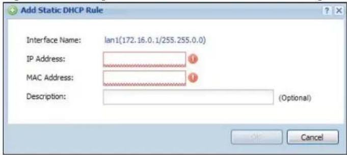
text_image
Add Static DHCP Rule Interface Name: lan1(172.16.0.1/255.255.0.0) IP Address: MAC Address: Description: (Optional) OK CancelThe following table describes the labels in this screen.
Table 96 Configuration > Network > IP/MAC Binding > Summary > Edit > Add/Edit
| LABEL DESCRIPTION | |
| Interface Name | This field displays the name of the interface within the UAG and the interface's IP address and subnet mask. |
| IP Address | Enter the IP address that the UAG is to assign to a device with the entry's MAC address. |
| MAC Address | Enter the MAC address of the device to which the UAG assigns the entry's IP address. |
| Description | Enter up to 64 printable ASCII characters to help identify the entry. For example, you may want to list the computer's owner. |
| OK | Click OK to save your changes back to the UAG. |
| Cancel | Click Cancel to exit this screen without saving. |
21.3 IP/MAC Binding Exempt List
Click Configuration > Network > IP/ MAC Binding > Exempt List to open the IP/ MAC Binding Exempt List screen. Use this screen to configure ranges of IP addresses to which the UAG does not apply IP/MAC binding.
Figure 144 Configuration > Network > IP/MAC Binding > Exempt List

text_image
Summary Exempt List IP/MAC Binding Exempt List Add Edit RemoveName → Start IP End IP
example Page 1 of 1 Show 50 items No data to display ApplyThe following table describes the labels in this screen.
Table 97 Configuration > Network > IP/MAC Binding > Exempt List
| LABEL DESCRIPTION | |
| Add Click this to add an entry to the table.If you click Add without selecting an entry in advance then the new entry appears as the first entry. | |
| Edit | Double-click an entry or select it and click Edit to be able to modify the entry's settings. |
| Remove | To remove an entry, select it and click Remove. The UAG confirms you want to remove it before doing so. |
| # This is the index number of the IP/MAC binding list entry. | |
| Name Enter a name to help identify this entry. | |
| Start IP | Enter the first IP address in a range of IP addresses for which the UAG does not apply IP/MAC binding. |
| End IP | Enter the last IP address in a range of IP addresses for which the UAG does not apply IP/MAC binding. |
| Apply | Click Apply to save your changes back to the UAG. |
Layer 2 Isolation
22.1 Overview
Layer-2 isolation is used to prevent connected devices from communicating with each other in the UAG's local network(s), on which layer-2 isolation is enabled, except the devices in the white list.
Note: Layer-2 isolation does not check the wireless traffic.
In the following example, layer-2 isolation is enabled on the UAG's interface Ian2. A printer, PC and AP are connected to Ian2. The IP address of the network printer (C) is added to the white list. The connected AP then cannot communicate with the PC (D), but can access the network printer (C), server (B), wireless client (A) and the Internet.
Figure 145 Layer-2 Isolation Application
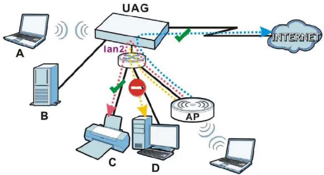
flowchart
graph TD
    A["Computer"] -->|A| B["Server"]
    B -->|B| C["Client"]
    C -->|C| D["Printer"]
    D -->|D| E["AP"]
    E -->|E| F["Internet"]
    F -->|F| G["UAG"]
    G -->|GND| H["LAN2"]
    H -->|HND| I["AP"]
    I -->|I| J["Client"]
    style H stroke:#ff0000,stroke-width:2px
    style I stroke:#ff0000,stroke-width:2px
    style J stroke:#ff0000,stroke-width:2px
22.1.1 What You Can Do in this Chapter
- Use the General screen (Section 22.2 on page 220) to enable layer-2 isolation on the UAG and the internal interface(s).
- Use the White List screen (Section 22.3 on page 220) to enable and configures the white list.
22.2 Layer-2 Isolation General Screen
This screen allows you to enable Layer-2 isolation on the UAG and specific internal interface(s). To access this screen click Configuration > Network > Layer 2 Isolation.
Figure 146 Configuration > Network > Layer 2 Isolation

text_image
General White List General Setting Enable Layer2 Isolation Member List Available dmz lan1 Member lan2 Apply ResetThe following table describes the labels in this screen.
Table 98 Configuration > Network > Layer 2 Isolation
| LABEL DESCRIPTION | |
| Enable Layer2 Isolation | Select this option to turn on the layer-2 isolation feature on the UAG.Note: You can enable this feature only when the firewall is enabled. |
| Member List | The Available list displays the name(s) of the internal interface(s) on which you can enable layer-2 isolation.To enable layer-2 isolation on an interface, you can double-click a single entry to move it or use the [Shift] or [Ctrl] key to select multiple entries and click the right arrow button to add to the Member list. To remove an interface, select the name(s) in the Member list and click the left arrow button. |
| Apply Click Apply | to save your changes back to the UAG. |
| Reset | Click Reset to return the screen to its last-saved settings. |
22.3 White List
IP addresses that are not listed in the white list are blocked from communicating with other devices in the layer-2-isolation-enabled internal interface(s) except for broadcast packets.
To access this screen click Configuration > Network > Layer 2 Isolation > White List.
Figure 147 Configuration > Network > Layer 2 Isolation > White List
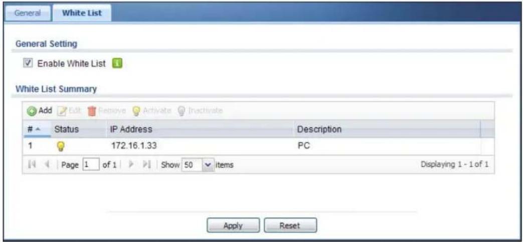
text_image
General White List General Setting Enable White List White List Summary Add Edit Repose Activate InactivateStatus IP Address Description
1 172.16.1.33 PC Page 1 of 1 Show 50 items Displaying 1 - 1 of 1 Apply ResetThe following table describes the labels in this screen.
Table 99 Configuration > Network > Layer 2 Isolation > White List
| LABEL DESCRIPTION | |
| Enable White List | Select this option to turn on the white list on the UAG.Note: You can enable this feature only when the firewall is enabled. |
| Add Click this to add a new rule. | |
| Edit Click this to edit the selected rule. | |
| Remove Click this to remove the selected rule. | |
| Activate | To turn on an entry, select it and click Activate. |
| Inactivate | To turn off an entry, select it and click Inactivate. |
| # This field is a sequential value, and it is not associated with a specific rule. | |
| Status | This icon is lit when the rule is active and dimmed when the rule is inactive. |
| IP Address | This field displays the IP address of device that can be accessed by the devices connected to an internal interface on which layer-2 isolation is enabled. |
| Description | This field displays the description for the IP address in this rule. |
| Apply Click Apply | to save your changes back to the UAG. |
| Reset | Click Reset to return the screen to its last-saved settings. |
22.3.1 Add/Edit White List Rule
This screen allows you to create a new rule in the white list or edit an existing one. To access this screen, click the Add button or select an entry from the list and click the Edit button.
Note: You can configure up to 20 white list rules on the UAG.
Note: You need to know the IP address of each connected device that you want to allow to be accessed by other devices when layer-2 isolation is enabled.
Figure 148 Configuration > Network > Layer 2 Isolation > White List > Add/Edit
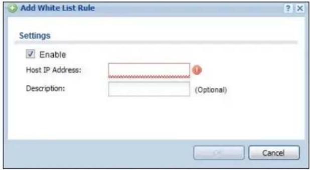
text_image
Add White List Rule Settings Enable Host IP Address: Description: (Optional) CancelThe following table describes the labels in this screen.
Table 100 Configuration > Network > Layer 2 Isolation > White List > Add/Edit
| LABEL DESCRIPTION | |
| Enable Select this | option to turn on the rule. |
| Host IP Address Enter an IPv4 address associated with this rule. | |
| Description | Specify a description for the IP address associated with this rule. Enter up to 60 characters, spaces and underscores allowed. |
| OK | Click OK to save your changes back to the UAG. |
| Cancel | Click Cancel to exit this screen without saving your changes. |
23.1 Overview
IP Plug and Play (IPnP) allows a computer to access the Internet without changing the network settings (such as IP address and subnet mask) of the computer, even when the IP addresses of the computer and the UAG are not in the same subnet.
When you disable the IPnP feature, only computers with dynamic IP addresses or static IP addresses in the same subnet as the UAG's LAN IP address can connect to the UAG or access the Internet through the UAG.
The IPnP feature does not apply to a computer using either a dynamic IP address or a static IP address that is in the same subnet as the UAG's IP address.
Note: You must enable NAT to use the IPnP feature.
The following figure depicts a scenario where a computer is set to use a static private IP address in the corporate environment. In a residential house where a UAG is installed, you can still use the computer to access the Internet without changing the network settings, even when the IP addresses of the computer and the UAG are not in the same subnet.
Figure 149 IPnP Application
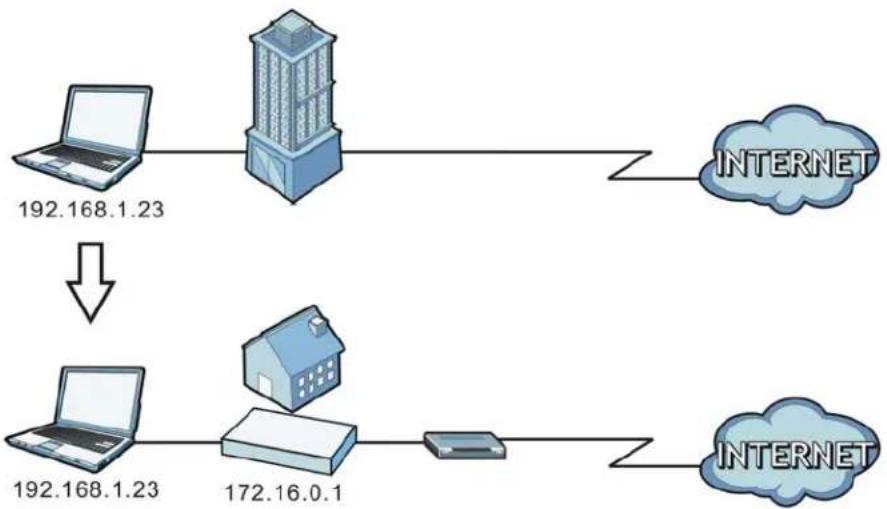
flowchart
graph TD
    A["192.168.1.23"] --> B["House"]
    B --> C["172.16.0.1"]
    C --> D["Server"]
    D --> E["INTERNET"]
    style A fill:#f9f,stroke:#333
    style B fill:#ccf,stroke:#333
    style C fill:#cfc,stroke:#333
    style D fill:#fcc,stroke:#333
    style E fill:#cff,stroke:#333
23.1.1 What You Can Do in this Chapter
Use the IP screen (Section 23.2 on page 224) to enable IPnP on the UAG and the internal interface(s).
23.2 IPnP Screen
This screen allows you to enable IPnP on the UAG and specific internal interface(s). To access this screen click Configuration > Network > IPnP.
Figure 150 Configuration > Network > IPnP

text_image
IPnP General Settings Enable IPnP Member List Available dmz lan1 Member lan2 Apply ResetThe following table describes the labels in this screen.
Table 101 Configuration > Network > IPnP
| LABEL DESCRIPTION | |
| Enable IPnP | Select this option to turn on the IPnP feature on the UAG.Note: You can enable this feature only when the firewall is enabled. |
| Member List | The Available list displays the name(s) of the internal interface(s) on which you can enable IPnP.To enable IPnP on an interface, you can double-click a single entry to move it or use the [Shift] or [Ctrl] key to select multiple entries and click the right arrow button to add to the Member list. To remove an interface, select the name(s) in the Member list and click the left arrow button. |
| Apply Click Apply | to save your changes back to the UAG. |
| Reset | Click Reset to return the screen to its last-saved settings. |
Web Authentication
24.1 Overview
Web authentication can intercepts network traffic, according to the authentication policies, until the user authenticates his or her connection, usually through a specifically designated login web page. This means all web page requests can initially be redirected to a special web page that requires users to authenticate their sessions. Once authentication is successful, they can then connect to the rest of the network or Internet.
As soon as a user attempt to open a web page, the UAG reroutes his/her browser to a web portal page that prompts he/she to log in.
Figure 151 Web Authentication Example
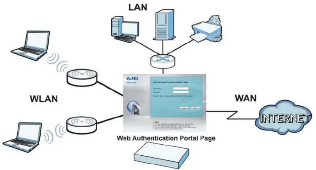
flowchart
graph TD
    A["LAN"] --> B["Router"]
    C["WLAN"] --> B
    D["Laptop"] --> B
    E["Laptop"] --> B
    F["Computer"] --> B
    G["Printer"] --> B
    H["Internet"] --> I["Web Authentication Portal Page"]
    J["WAN"] --> I
    B --> K["ZyXEL UACHELS"]
    B --> L["Web Authentication Portal Page"]
    style B fill:#f9f,stroke:#333
    style I fill:#ccf,stroke:#333
The web authentication page only appears once per authentication session. Unless a user session times out or he/she closes the connection, he or she generally will not see it again during the same session.
24.1.1 What You Can Do in this Chapter
- Use the Configuration > Web Authentication screens (Section 24.2 on page 226) to create and manage web authentication policies.
- Use the Configuration > Web Authentication > Walled Garden screens (Section 24.3 on page 240) to enable and create walled garden links that display in the login screen.
- Use the Configuration > Web Authentication > Advertisement screens (Section 24.4 on page 242) to enable and set advertisement links.
24.1.2 What You Need to Know
Forced User Authentication
Instead of making users for which user-aware policies have been configured go to the UAG Login screen manually, you can configure the UAG to display the Login screen automatically whenever it routes HTTP traffic for anyone who has not logged in yet.
Note: This works with HTTP traffic only. The UAG does not display the Login screen when users attempt to send other kinds of traffic.
The UAG does not automatically route the request that prompted the login, however, so users have to make this request again.
Finding Out More
See Section 24.2.2 on page 233 for an example of using an authentication policy for user-aware access control.
24.2 Web Authentication Screen
The Web Authentication screen displays the web portal settings and web authentication policies you have configured on the UAG. The screen differs depending on what you select in the Authentication field.
Click Configuration > Web Authentication to display the screen.
Figure 152 Configuration > Web Authentication (Web Portal)
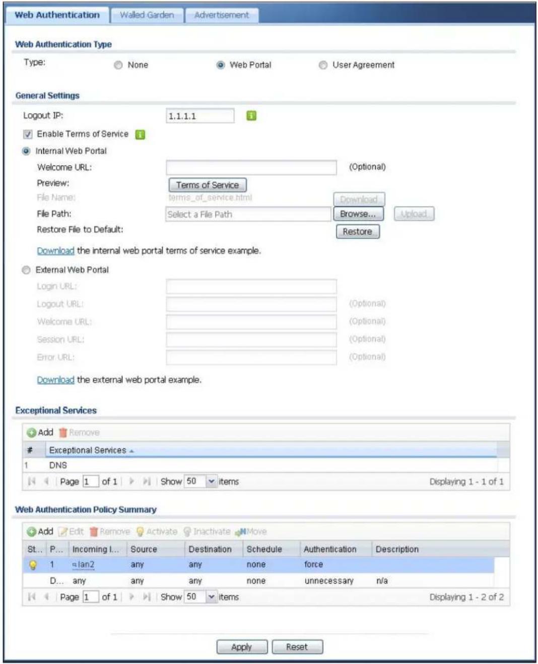
text_image
Web Authentication Walled Garden Advertisement Web Authentication Type Type: None Web Portal User Agreement General Settings Logout IP: 1.1.1.1 Enable Terms of Service Internal Web Portal Welcome URL: (Optional) Preview: Terms of Service File Name: terms_of_service.html Download... File Path: Select a File Path Browse... Upload... Restore File to Default: Restore Download the internal web portal terms of service example. External Web Portal Login URL: (Optional) Logout URL: (Optional) Welcome URL: (Optional) Session URL: (Optional) Error URL: (Optional) Download the external web portal example. Exceptional Services Add RemoveExceptional Services
1 DNS Page 1 of 1 Show 50 items Displaying 1 - 1 of 1 Web Authentication Policy Summary Add Edit Remove Activate Inactivate Move St... P... Incoming I... Source Destination Schedule Authentication Description 1 lan2 any any none force D... any any any none unnecessary n/a Page 1 of 1 Show 50 items Displaying 1 - 2 of 2 Apply ResetFigure 153 Configuration > Web Authentication (User Agreement)
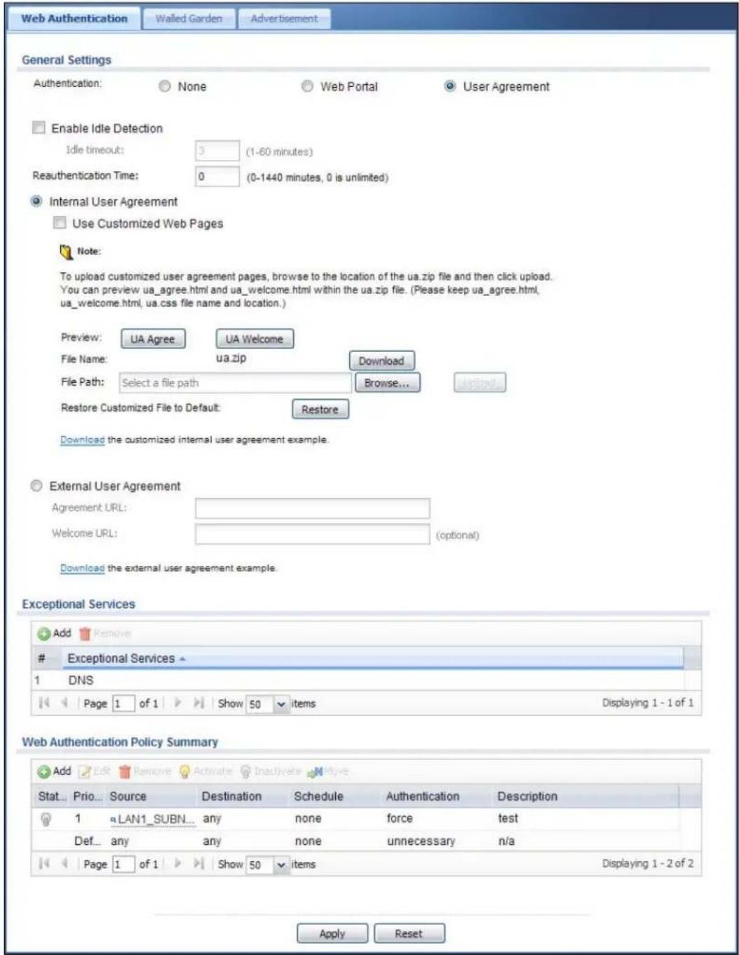
text_image
Web Authentication Walled Garden Advertisement General Settings Authentication: None Web Portal User Agreement Enable Idle Detection Idle timeout: 3 (1-60 minutes) Reauthentication Time: 0 (0-1440 minutes, 0 is unlimited) Internal User Agreement Use Customized Web Pages Note: To upload customized user agreement pages, browse to the location of the ua.zip file and then click upload. You can preview ua_agree.html and ua_welcome.html within the ua.zip file. (Please keep ua_agree.html, ua_welcome.html, ua.css file name and location.) Preview: UA Agree UA Welcome File Name: ua.zip Download File Path: Select a file path Browse... Restore Customized File to Default: Restore Download the customized internal user agreement example. External User Agreement Agreement URL: Welcome URL: (optional) Download the external user agreement example. Exceptional Services Add RemoveExceptional Services
1 DNS Page 1 of 1 Show 50 items Displaying 1 - 1 of 1 Web Authentication Policy Summary Add Edit Remove Activate Inactivate Improve Stat... Prio... Source Destination Schedule Authentication Description 1 LAN1_SUBN... any none force test Def... any any none unnecessary n/a Page 1 of 1 Show 50 items Displaying 1 - 2 of 2 Apply ResetThe following table gives an overview of the objects you can configure.
Table 102 Configuration > Web Authentication
| LABEL DESCRIPTION | |
| Authentication | Select Web Portal or User Agreement to turn on the web authentication feature. Otherwise, select None to turn it off.Once enabled, all network traffic is blocked until a client authenticates with the UAG through the specifically designated web portal or user agreement page.If you select User agreement, by agreeing to the policy of user agreement, users can access the Internet without a guest account. |
| The following fields are available if you set Authentication to Web Portal. | |
| Logout IP Specify | an IP address that users can use to terminate their sessions manually by entering the IP address in the address bar of the web browser. |
| Enable Terms of Service | Select this option to force users to agree to the terms before they can use the service. An agreement checkbox will display in the login page. |
| Internal Web Portal | Select this to use the default login page built into the UAG. If you later assign a custom login page, you can still return to the UAG's default page as it is saved indefinitely.The login page appears whenever the web portal intercepts network traffic, preventing unauthorized users from gaining access to the network.You can customize the login page built into the UAG in the System > WWW > Login Page screen. |
| Welcome URL | Specify the welcome page's URL; for example, http://IIS server IP Address/welcome.html.Users will be redirected to the welcome page after authentication. This field is optional.The Internet Information Server (IIS) is the web server on which the web portal files are installed. |
| Preview Click a | button to display the "Terms of Service" page you uploaded to the UAG. |
| File Name This | shows the file name of the "Terms of Service" page in the UAG.Click Download to download the "Terms of Service" page from the UAG to your computer. |
| File Path /Browse /Upload | Browse for the "Terms of Service" page or enter the file path in the available input box, then click the Upload button to put it on the UAG. |
| Restore File to Default | Click Restore to set the UAG back to use the default "Terms of Service" page. |
| Download | Click this to download an example internal "Terms of Service" page from the UAG for your reference. |
| External Web Portal | Select this to use a custom login page from an external web portal instead of the default one built into the UAG. You can configure the look and feel of the web portal page. |
| Login URL | Specify the login page's URL; for example, http://IIS server IP Address/login.html.The Internet Information Server (IIS) is the web server on which the web portal files are installed. |
| Logout URL | Specify the logout page's URL; for example, http://IIS server IP Address/logout.html.The Internet Information Server (IIS) is the web server on which the web portal files are installed. |
| Welcome URL | Specify the welcome page's URL; for example, http://IIS server IP Address/welcome.html.The Internet Information Server (IIS) is the web server on which the web portal files are installed. |
| Session URL | Specify the session page's URL; for example, http://IIS server IP Address/session.html.The Internet Information Server (IIS) is the web server on which the web portal files are installed. |
| Error URL | Specify the error page's URL; for example, http://IIS server IP Address/error.html.The Internet Information Server (IIS) is the web server on which the web portal files are installed. |
| Download | Click this to download an example web portal file for your reference. |
| The following fields are available if you set Authentication to User Agreement. | |
| Enable Idle Detection | This is applicable for access users.Select this check box if you want the UAG to monitor how long each access user is logged in and idle (in other words, there is no traffic for this access user). The UAG automatically logs out the access user once the Idle timeout has been reached. |
| Idle timeout This is applicable for access users.This field is effective when Enable Idle Detection is checked. Type the number of minutes each access user can be logged in and idle before the UAG automatically logs out the access user. | |
| Reauthentication Time | Enter the number of minutes the user can be logged into the UAG in one session before having to log in again. |
| Internal User Agreement | Select this to use the user agreement pages built into the UAG. The user agreement page appears whenever the UAG intercepts network traffic, preventing unauthorized users from gaining access to the network. |
| Use Customized Web Pages | Select this to use the custom user agreement pages that are uploaded to the UAG. |
| Preview Click a button to display the corresponding page you uploaded to the UAG. | |
| File Name This shows the file name of the zipped user agreement file in the UAG.Click Download to download the user agreement file from the UAG to your computer. | |
| File Path /Browse /Upload | Browse for the user agreement file or enter the file path in the available input box, then click the Upload button to put it on the UAG. |
| Restore Customization File to Default | Click Restore to set the UAG back to use the default built-in user agreement pages. |
| Download | Click this to download an example internal user agreement file from the UAG for your reference. |
| External User Agreement | Select this to use custom user agreement pages from an external web server instead of the default one built into the UAG. You can configure the look and feel of the user agreement page. |
| Agreement URL | Specify the user agreement page's URL; for example, http://IIS server IP Address/logout.html.The Internet Information Server (IIS) is the web server on which the user agreement files are installed. |
| Welcome URL | Specify the welcome page's URL; for example, http://IIS server IP Address/welcome.html.The Internet Information Server (IIS) is the web server on which the user agreement files are installed.If you leave this field blank, the UAG will use the welcome page of internal user agreement file. |
| Download | Click this to download an example external user agreement file for your reference. |
| The following fields are available if you set Authentication to Web Portal or User Agreement. | |
| Exceptional Services | Use this table to list services that users can access without logging in.ClickAddto change the list's membership. A screen appears. Available services appear on the left. Select any services you want users to be able to access without logging in and click the right arrow button to add them. The member services are on the right. Select any service that you want to remove from the member list, and click the left arrow button to remove them.Keeping DNS as a member allows users' computers to resolve domain names into IP addresses.Figure 154 Configuration > Web Authentication > Add Exceptional Service In the table, select one or more entries and clickRemoveto delete it or them. In the table, select one or more entries and clickRemoveto delete it or them. |
| Web Authentication Policy Summary | Use this table to manage the UAG's list of web authentication policies. |
| Add | Click this to create a new entry. Select an entry and clickAddto create a new entry after the selected entry. |
| Edit | Double-click an entry or select it and clickEditto open a screen where you can modify the entry's settings. |
| Remove | To remove an entry, select it and clickRemove. The UAG confirms you want to remove it before doing so. |
| Activate | To turn on an entry, select it and clickActivate. |
| Inactivate | To turn off an entry, select it and click Inactivate. |
| Move | To move an entry to a different number in the list, click theMoveicon. In the field that appears, specify the number to which you want to move the interface. |
| Status This icon is | lit when the entry is active and dimmed when the entry is inactive. |
| Priority This is the | position of the authentication policy in the list. The priority is important as the policies are applied in order of priority.Defaultdisplays for the default authentication policy that the UAG uses on traffic that does not match any exceptional service or other authentication policy. You can edit the default rule but not delete it. |
| Incoming Interface | This field displays the interface on which packets for this policy are received. |
| Source This displays the source address object to which this policy applies. | |
| Destination This displays the destination address object to which this policy applies. | |
| Schedule | This field displays the schedule object that dictates when the policy applies. none means the policy is active at all times if enabled. |
| Authentication | This field displays the authentication requirement for users when their traffic matches this policy.unnecessary- Users do not need to be authenticated.required- Users need to be authenticated. They must manually go to the login screen. The UAG will not redirect them to the login screen.force- Users need to be authenticated. The UAG automatically displays the login screen whenever it routes HTTP traffic for users who have not logged in yet. |
| Description | If the entry has a description configured, it displays here. This is n/ a for the default policy. |
| Apply Click this button to save your changes to the UAG. | |
| Reset | Click this button to return the screen to its last-saved settings. |
24.2.1 Adding/Editing an Authentication Policy
Open the Configuration > Web Authentication screen, then click the Add icon or select an entry and click the Edit icon in the Web Authentication Policy Summary section to open the Auth. Policy Add/ Edit screen. Use this screen to configure an authentication policy.
Figure 155 Configuration > Web Authentication > Add

text_image
Auth. Policy Add Create new Object General Settings Enable Policy Description: (Optional) User Authentication Policy Incoming Interface: any Source Address: any Destination Address: any Schedule: none Authentication: required Force User Authentication OK CancelThe following table gives an overview of the objects you can configure.
Table 103 Configuration > Web Authentication > Add/Edit
| LABEL DESCRIPTION | |
| Create new Object | Use to configure any new settings objects that you need to use in this screen. |
| Enable Policy | Select this check box to activate the authentication policy. This field is available for user-configured policies. |
| Description | Enter a descriptive name of up to 60 printable ASCII characters for the policy. Spaces are allowed. This field is available for user-configured policies. |
| User Authentication Policy | Use this section of the screen to determine which traffic requires (or does not require) the senders to be authenticated in order to be routed. |
| Incoming Interface | Select an interface on which packets for the policy must be received. Select any if the policy is effective for every interface. |
| Source Address | Select a source address or address group for whom this policy applies. Select any if the policy is effective for every source. This is any and not configurable for the default policy. |
| Destination Address | Select a destination address or address group for whom this policy applies. Select any if the policy is effective for every destination. This is any and not configurable for the default policy. |
| Schedule | Select a schedule that defines when the policy applies. Otherwise, select none and the rule is always effective. This is none and not configurable for the default policy. |
| Authentication | Select the authentication requirement for users when their traffic matches this policy.unnecessary - Users do not need to be authenticated.required - Users need to be authenticated. If Force User Authentication is selected, all HTTP traffic from unauthenticated users is redirected to a default or user-defined login page. Otherwise, they must manually go to the login screen. The UAG will not redirect them to the login screen. |
| Log | This field is available for the default policy. Select whether to have the UAG generate a log (log), log and alert (log alert) or not (no) for packets that match the default policy. See Chapter 42 on page 435 for more on logs. |
| Force User Authentication | This field is available for user-configured policies that require authentication. Select this to have the UAG automatically display the login screen when users who have not logged in yet try to send HTTP traffic. |
| OK | Click OK to save your changes back to the UAG. |
| Cancel | Click Cancel to exit this screen without saving. |
24.2.2 User-aware Access Control Example
You can configure many policies and security settings for specific users or groups of users. Users can be authenticated locally by the UAG or by an external (RADIUS) authentication server.
In this example the users are authenticated by an external RADIUS server at 172.16.1.200. First, set up the user accounts and user groups in the UAG. Then, set up user authentication using the RADIUS server. Finally, set up the policies in the table above.
24.2.2.1 Set Up User Accounts
Set up user accounts in the RADIUS server. This example uses the Web Configurator. If you can export user names from the RADIUS server to a text file, then you might configure a script to create the user accounts instead.
1 Click Configuration > Object > User/ Group > User. Click the Add icon.
2 Enter the same user name that is used in the RADIUS server, and set the User Type to ext-user because this user account is authenticated by an external server. Click OK.
Figure 156 Configuration > Object > User/Group > User > Add
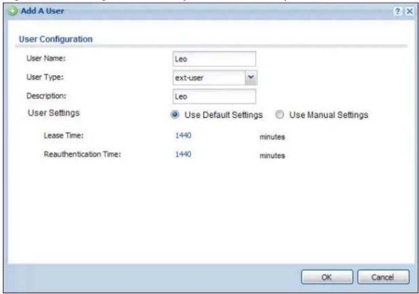
text_image
Add A User User Configuration User Name: Leo User Type: ext-user Description: Leo User Settings Use Default Settings Use Manual Settings Lease Time: 1440 minutes Reauthentication Time: 1440 minutes OK Cancel3 Repeat this process to set up the remaining user accounts.
24.2.2.2 Set Up User Groups
Set up the user groups and assign the users to the user groups.
1 Click Configuration > Object > User/ Group > Group. Click the Add icon.
2 Enter the name of the group. In this example, it is "Finance". Then, select Object/Leo and click the right arrow to move him to the Member list. This example only has one member in this group, so click OK. Of course you could add more members later.
Figure 157 Configuration > Object > User/Group > Group > Add
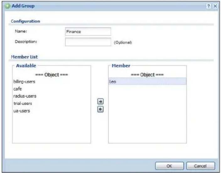
text_image
Add Group Configuration Name: Finance Description: (Optional) Member List Available === Object === billing-users cafe radius-users trial-users ua-users Member === Object === Leo OK Cancel3 Repeat this process to set up the remaining user groups.
24.2.2.3 Set Up User Authentication Using the RADIUS Server
This step sets up user authentication using the RADIUS server. First, configure the settings for the RADIUS server. Then, set up the authentication method, and configure the UAG to use the authentication method. Finally, force users to log into the UAG before it routes traffic for them.
1 Click Configuration > Object > AAA Server > RADIUS. Double-click the radius entry. Configure the RADIUS server's address, authentication port (1812 if you were not told otherwise), and key. Click Apply.
Figure 158 Configuration > Object > AAA Server > RADIUS > Add

text_image
Add RADIUS General Settings Name: New Description: (Optional) Server Settings Server Address: 172.16.1.200 (IP or FQDN) Authentication Port: 1812 (1-65535) Backup Server Address: (IP or FQDN) (Optional) Backup Authentication Port: (1-65535) (Optional) Timeout: 5 (1-300 seconds) NAS IP Address: 127.0.0.1 (IP Address) ✓ Case-sensitive User Names Server Authentication Key: •••••• User Login Settings Group Membership Attribute: Filter-Id(11) 11 OK Cancel2 Click Configuration > Object > Auth. Method. Double-click the default entry. Click the Add icon. Select group radius because the UAG should use the specified RADIUS server for authentication. Click OK.
Figure 159 Configuration > Object > Auth. method > Edit

text_image
Edit Authentication Method default General Settings Name: default Add Edit Remove MoveMethod List
1 group radius 2 bcal OK Cancel3 Click Configuration > Web Authentication. In the Web Authentication screen, select Web Portal to enable web authentication and click Apply.
Figure 160 Configuration > Web Authentication
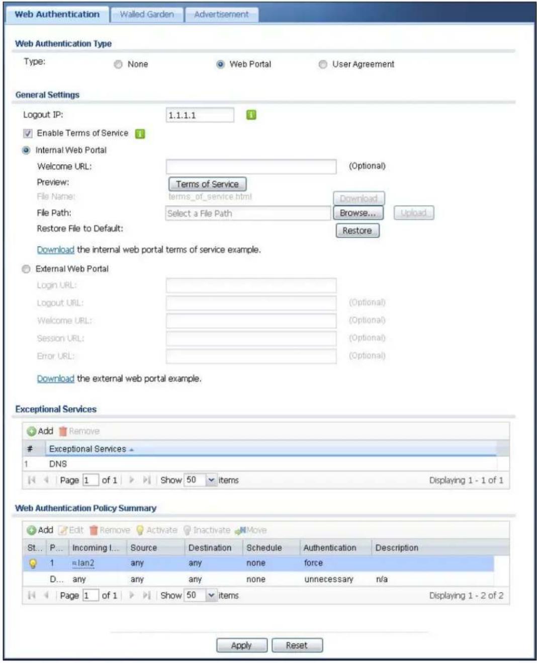
text_image
Web Authentication Walled Garden Advertisement Web Authentication Type Type: None Web Portal User Agreement General Settings Logout IP: 1.1.1.1 Enable Terms of Service Internal Web Portal Welcome URL: (Optional) Preview: Terms of Service File Name: terms_of_service.html Download... File Path: Select a File Path Browse... Upload... Restore File to Default: Restore Download the internal web portal terms of service example. External Web Portal Login URL: (Optional) Logout URL: (Optional) Welcome URL: (Optional) Session URL: (Optional) Error URL: (Optional) Download the external web portal example. Exceptional Services Add RemoveExceptional Services
1 DNS Page 1 of 1 Show 50 items Displaying 1 - 1 of 1 Web Authentication Policy Summary Add Edit Remove Activate Inactivate Move St... P... Incoming I... Source Destination Schedule Authentication Description 1 lan2 any any none force D... any any any none unnecessary n/a Page 1 of 1 Show 50 items Displaying 1 - 2 of 2 Apply Reset4 In the Web Authentication Policy Summary section, click the Add icon.
5 Set up a default policy that forces every user to log into the UAG before the UAG routes traffic for them. Select Enable Policy. Set the Authentication field to required, and make sure Force User Authentication is selected. Keep the rest of the default settings, and click OK.
Note: The users must log in at the Web Configurator login screen before they can use HTTP or MSN.
Figure 161 Configuration > Web Authentication > Add

text_image
Auth. Policy Add Create new Object General Settings Enable Policy Description: default_policy (Optional) User Authentication Policy Incoming Interface: any Source Address: any Destination Address: any Schedule: none Authentication: required Force User Authentication OK CancelWhen the users try to browse the web (or use any HTTP application), the login screen appears. They have to log in using the user name and password in the RADIUS server.
24.2.2.4 User Group Authentication Using the RADIUS Server
The previous example showed how to have a RADIUS server authenticate individual user accounts. If the RADIUS server has different user groups distinguished by the value of a specific attribute, you can make a couple of slight changes in the configuration to have the RADIUS server authenticate groups of user accounts defined in the RADIUS server.
1 Click Configuration > Object > AAA Server > RADIUS. Double-click the radius entry. Besides configuring the RADIUS server's address, authentication port, and key; set the Group Membership Attribute field to the attribute that the UAG is to check to determine to which group a user belongs. This example uses Class. This attribute's value is called a group identifier; it determines to which group a user belongs. In this example the values are Finance, Engineer, Sales, and Boss.
Figure 162 Configuration > Object > AAA Server > RADIUS > Add
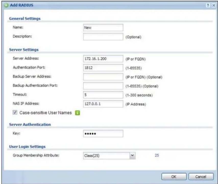
text_image
Add RADIUS General Settings Name: New Description: (Optional) Server Settings Server Address: 172.16.1.200 (IP or FQDN) Authentication Port: 1812 (1-65535) Backup Server Address: (IP or FQDN) (Optional) Backup Authentication Port: (1-65535) (Optional) Timeout: 5 (1-300 seconds) NAS IP Address: 127.0.0.1 (IP Address) ✓ Case-sensitive User Names Server Authentication Key: •••••• User Login Settings Group Membership Attribute: Class(25) 25 OK Cancel2 Now you add ext-group-user user objects to identify groups based on the group identifier values. Set up one user account for each group of user accounts in the RADIUS server. Click Configuration > Object > User/ Group > User. Click the Add icon.
Enter a user name and set the User Type to ext-group-user. In the Group Identifier field, enter Finance, Engineer, Sales, or Boss and set the Associated AAA Server Object to radius.
Figure 163 Configuration > Object > User/Group > User > Add

text_image
Add A User User Configuration User Name: Finance User Type: ext-group-user Group Identifier: Finance Associated AAA Server Object: radius Description: Local User User Settings Use Default Settings Use Manual Settings Lease Time: 1440 minutes Reauthentication Time: 1440 minutes OK Cancel3 Repeat this process to set up the remaining groups of user accounts.
24.3 Walled Garden Screen
A user must log in before the UAG allows the user's access to the Internet. However, with a walled garden, you can define one or more web site addresses that all users can access without logging in. These can be used for advertisements for example.
Use this screen to configure walled garden web addresses for web sites that all users are allowed to access without logging in. The web site link(s) then displays in the user login screen.
Click Configuration > Web Authentication > Walled Garden to display the screen.
Figure 164 Configuration > Web Authentication > Walled Garden

text_image
Web Authentication Walled Garden Advertisement General Settings Enable Walled Garden Walled Garden Summary Add Edit Remove Activate Inactivate MoveStatus Display Name URL
1 WalledGardenLink2 http://www.zyxel.com 2 WalledGardenLink1 http://www.example.com Page 1 of 1 Show 50 items Displaying 1 - 2 of 2 Apply ResetThe following table gives an overview of the objects you can configure.
Table 104 Configuration > Web Authentication > Walled Garden
| LABEL DESCRIPTION | |
| Enable Walled Garden | Select this to turn on the walled garden feature.Note: This feature works only when you set web authentication to Web Portal. |
| Walled Garden Summary | Use this table to manage the list of walled garden links. |
| Add | Click this to create a new entry. Select an entry and click Add to create a new entry after the selected entry. |
| Edit | Double-click an entry or select it and click Edit to open a screen where you can modify the entry's settings. |
| Remove | To remove an entry, select it and click Remove. The UAG confirms you want to remove it before doing so. |
| Activate | To turn on an entry, select it and click Activate. |
| Inactivate | To turn off an entry, select it and click Inactivate. |
| Move | To move an entry to a different number in the list, click the Move icon. In the field that appears, specify the number to which you want to move the interface. |
| # | This field is a sequential value, and it is not associated with any entry. |
| Status This icon is | lit when the entry is active and dimmed when the entry is inactive. |
| Display | This icon is lit when the web site link is set to display in the user login screen. |
| Name This field displays the descriptive name of web site. | |
| URL This field displays the address of web site. | |
| Apply Click this button to save your changes to the UAG. | |
| Reset | Click this button to return the screen to its last-saved settings. |
24.3.1 Adding/Editing a Walled Garden URL
In the Configuration > Web Authentication > Walled Garden screen, click the Add icon or select an entry and click the Edit icon in the Walled Garden Summary section to open the Add/Edit Walled Garden URL screen. Use this screen to configure a walled garden web site address entry.
Note: You can configure up to 20 walled garden URL links.
Figure 165 Configuration > Web Authentication > Walled Garden > Add/Edit

text_image
Edit Walled Garden URL Settings Enable Hide in login page Name: WalledGardenLink2 URL: http://www.zyxel.cor Preview OK CancelThe following table gives an overview of the objects you can configure.
Table 105 Configuration > Web Authentication > Walled Garden > Add/Edit
| LABEL DESCRIPTION | |
| Enable Select this to activate the entry. | |
| Hide in login page | Select this to not display the web site link in the user login screen.This is helpful if a user's access to a specific web site is required to stay connected but he or she doesn't need to visit that web site. |
| Name | Enter a descriptive name for the walled garden link to be displayed in the login screen.You can use up to 31 alphanumeric characters (A-Z, a-z, 0-9) and underscores (_). Spaces are not allowed. The first character must be a letter. |
| URL Enter the URL or IP address of the web site.Use "http://" followed by up to 262 characters (0-9a-zA-Z;/?:@&=+$\._!~*')(%)%. For example, http://www.example.com or http://172.16.1.35. | |
| Preview Click this | button to open the specified web site in a new frame. |
| OK | Click OK to save your changes back to the UAG. |
| Cancel | Click Cancel to exit this screen without saving. |
24.3.2 Walled Garden Login Example
The following figure shows the user login screen with two walled garden links. The links are named WalledGardenLink1 through 2 for demonstration purposes.
Figure 166 Walled Garden Login Example
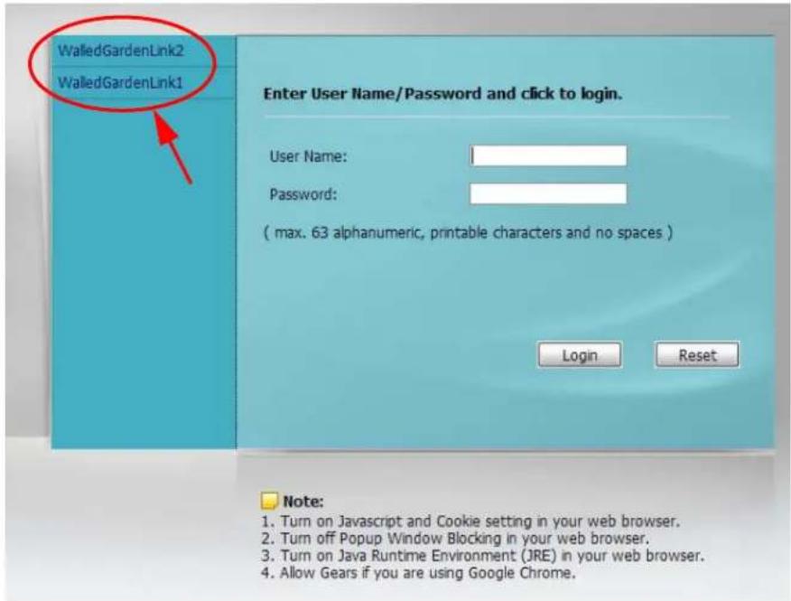
text_image
WalledGardenLink2 WalledGardenLink1 Enter User Name/Password and click to login. User Name: Password: ( max. 63 alphanumeric, printable characters and no spaces ) Login Reset Note: 1. Turn on Javascript and Cookie setting in your web browser. 2. Turn off Popup Window Blocking in your web browser. 3. Turn on Java Runtime Environment (JRE) in your web browser. 4. Allow Gears if you are using Google Chrome.24.4 Advertisement Screen
Use this screen to set the UAG to display an advertisement web page as the first web page whenever the user connects to the Internet.
Click Configuration > Web Authentication > Advertisement to display the screen.
Figure 167 Configuration > Web Authentication > Advertisement

text_image
Web Authentication Walled Garden Advertisement General Settings Enable Advertisement Advertisement Summary Add Edit RemoveName URL
1 example http://www.zyxel.com Page 1 of 1 Show 50 items Displaying 1 - 1 of 1 Apply ResetThe following table gives an overview of the objects you can configure.
Table 106 Configuration > Web Authentication > Advertisement
| LABEL DESCRIPTION | |
| Enable Advertisement | Select this to turn on the advertisement feature. Note: This feature works only when you enable web authentication. |
| Advertisement Summary | Use this table to manage the list of advertisement web pages. |
| Add | Click this to create a new entry. Select an entry and click Add to create a new entry after the selected entry. |
| Edit | Double-click an entry or select it and click Edit to open a screen where you can modify the entry's settings. |
| Remove | To remove an entry, select it and click Remove. The UAG confirms you want to remove it before doing so. |
| Activate | To turn on an entry, select it and click Activate. |
| Inactivate | To turn off an entry, select it and click Inactivate. |
| Move | To move an entry to a different number in the list, click the Move icon. In the field that appears, specify the number to which you want to move the interface. |
| # | This field is a sequential value, and it is not associated with any entry. |
| Status This icon is | lit when the entry is active and dimmed when the entry is inactive. |
| Name This field displays the descriptive name of web site. | |
| URL This field displays the address of web site. | |
| Apply Click this button to save your changes to the UAG. | |
| Reset | Click this button to return the screen to its last-saved settings. |
24.4.1 Adding/Editing an Advertisement URL
Go to Configuration > Web Authentication > Advertisement, and then click the Add icon or select an entry and click the Edit icon in the Advertisement Summary section to open the Add/Edit Advertisement URL screen. Use this screen to configure an advertisement address entry.
Note: You can create up to 20 advertisement URL entries. The UAG randomly picks one and open the specified web site in a new frame when an authenticated user is attempts to access the Internet.
Figure 168 Configuration > Web Authentication > Advertisement > Add/Edit
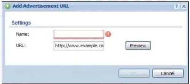
text_image
Add Advertisement URL Settings Name: URL: http://www.example.co Preview CancelThe following table gives an overview of the objects you can configure.
Table 107 Configuration > Web Authentication > Advertisement > Add/Edit
| LABEL DESCRIPTION | |
| Enable Select this to activate the entry. | |
| Name | Enter a descriptive name for the advertisement web site.You can use up to 31 alphanumeric characters (A-Z, a-z, 0-9) and underscores (_). Spaces are not allowed. The first character must be a letter. |
| URL Enter the URL or IP address of the web site.Use "http://" followed by up to 262 characters (0-9a-zA-Z;/?:@&=+$\._!~*')%). For example, http://www.example.com or http://172.16.1.35. | |
| Preview Click this button to open the specified web site in a new frame. | |
| OK | Click OK to save your changes back to the UAG. |
| Cancel | Click Cancel to exit this screen without saving. |
25.1 Overview
Use the firewall to block or allow services that use static port numbers. The firewall can also limit the number of user sessions.
This example shows the UAG's default firewall behavior for WAN to LAN traffic and how stateful inspection works. A LAN user can initiate a Telnet session from within the LAN zone and the firewall allows the response. However, the firewall blocks Telnet traffic initiated from the WAN zone and destined for the LAN zone. The firewall allows VPN traffic between any of the networks.
Figure 169 Default Firewall Action
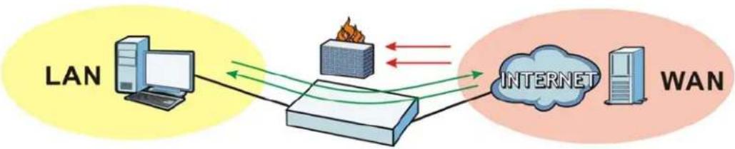
flowchart
graph LR
    A["LAN"] --> B["Computer"]
    B --> C["Router"]
    C --> D["INTERNET"]
    D --> E["WAN"]
    style A fill:#FFD700,stroke:#333
    style B fill:#FFA500,stroke:#333
    style C fill:#E6F2FF,stroke:#333
    style D fill:#B2C4A2,stroke:#333
    style E fill:#FFD700,stroke:#333
25.1.1 What You Can Do in this Chapter
- Use the Firewall screens (Section 25.2 on page 247) to enable or disable the firewall and asymmetrical routes, and manage and configure firewall rules.
- Use the Session Control screens (see Section 25.3 on page 252) to limit the number of concurrent NAT/firewall sessions a client can use.
25.1.2 What You Need to Know
Stateful Inspection
The UAG has a stateful inspection firewall. The UAG restricts access by screening data packets against defined access rules. It also inspects sessions. For example, traffic from one zone is not allowed unless it is initiated by a computer in another zone first.
Zones
A zone is a group of interfaces or VPN tunnels. Group the UAG's interfaces into different zones based on your needs. You can configure firewall rules for data passing between zones or even between interfaces and/or VPN tunnels in a zone.
Default Firewall Behavior
Firewall rules are grouped based on the direction of travel of packets to which they apply. Here is the default firewall behavior for traffic going through the UAG in various directions.
Table 108 Default Firewall Behavior
| FROM ZONE TO ZONE BEHAVIOR | |
| From any to Device DHCP traffic from any interface to the UAG is allowed. | |
| From LAN1 to any (other than the UAG) | Traffic from the LAN1 to any of the networks connected to the UAG is allowed. |
| From LAN2 to any (other than the UAG) | Traffic from the LAN2 to any of the networks connected to the UAG is allowed. |
| From DMZ to WAN Traffic from the DMZ to the WAN is allowed. | |
| From IPSec VPN to any (other than the UAG) | Traffic from the IPSec VPN zone to any of the networks connected to the UAG is allowed. |
| From LAN1 to Device Traffic from the LAN1 to the UAG itself is allowed. | |
| From LAN2 to Device Traffic from the LAN2 to the UAG itself is allowed. | |
| From DMZ to Device DNS and NetBIOS traffic from the DMZ to the UAG itself is allowed. | |
| From IPSec VPN to Device Traffic from the IPSec VPN zone to the UAG itself is allowed. | |
| From WAN to Device | The default services listed in To-Device Rules on page 246 are allowed from the WAN to the UAG itself. All other WAN to UAG traffic is dropped. |
| From any to any | Traffic that does not match any firewall rule is dropped. This includes traffic from the WAN to any of the networks behind the UAG.This also includes traffic to or from interfaces that are not assigned to a zone (extra-zone traffic). |
To-Device Rules
Rules with Device as the To Zone apply to traffic going to the UAG itself. By default:
- The firewall allows only LAN, or WAN computers to access or manage the UAG.
- The UAG allows DHCP traffic from any interface to the UAG.
- The UAG drops most packets from the DMZ zone to the UAG itself and generates a log except for DNS and NetBIOS traffic.
- The UAG drops most packets from the WAN zone to the UAG itself and generates a log except for AH, ESP, GRE, HTTPS, IKE, NATT.
When you configure a firewall rule for packets destined for the UAG itself, make sure it does not conflict with your service control rule. See Chapter 41 on page 394 for more information about service control (remote management). The UAG checks the firewall rules before the service control rules for traffic destined for the UAG.
A From Any To Device direction rule applies to traffic from an interface which is not in a zone.
Global Firewall Rules
Firewall rules with from any and/or to any as the packet direction are called global firewall rules. The global firewall rules are the only firewall rules that apply to an interface or VPN tunnel that is not included in a zone. The from any rules apply to traffic coming from the interface and the to any rules apply to traffic going to the interface.
Firewall Rule Criteria
The UAG checks the schedule, user name (user's login name on the UAG), source IP address, destination IP address and IP protocol type of network traffic against the firewall rules (in the order you list them). When the traffic matches a rule, the UAG takes the action specified in the rule.
User Specific Firewall Rules
You can specify users or user groups in firewall rules. For example, to allow a specific user from any computer to access a zone by logging in to the UAG, you can set up a rule based on the user name only. If you also apply a schedule to the firewall rule, the user can only access the network at the scheduled time. A user-aware firewall rule is activated whenever the user logs in to the UAG and will be disabled after the user logs out of the UAG.
Firewall and VPN Traffic
After you create a VPN tunnel and add it to a zone, you can set the firewall rules applied to VPN traffic. If you add a VPN tunnel to an existing zone (the LAN1 zone for example), you can configure a new LAN1 to LAN1 firewall rule to allow or block VPN traffic transmitting between the VPN tunnel and other interfaces in the LAN zone. If you add the VPN tunnel to a new zone (the VPN zone for example), you can configure rules for VPN traffic between the VPN zone and other zones or From VPN To-Device rules for VPN traffic destined for the UAG.
Session Limits
Accessing the UAG or network resources through the UAG requires a NAT session and corresponding firewall session. Peer to peer applications, such as file sharing applications, may use a large number of NAT sessions. A single client could use all of the available NAT sessions and prevent others from connecting to or through the UAG. The UAG lets you limit the number of concurrent NAT/firewall sessions a client can use.
Finding Out More
- See Section 25.4 on page 254 for an example of creating firewall rules as part of configuring user-aware access control.
25.2 The Firewall Screen
Asymmetrical Routes
If an alternate gateway on the LAN has an IP address in the same subnet as the UAG's LAN IP address, return traffic may not go through the UAG. This is called an asymmetrical or "triangle" route. This causes the UAG to reset the connection, as the connection has not been acknowledged.
You can have the UAG permit the use of asymmetrical route topology on the network (not reset the connection). However, allowing asymmetrical routes may let traffic from the WAN go directly to the LAN without passing through the UAG. A better solution is to use virtual interfaces to put the UAG and the backup gateway on separate subnets. Virtual interfaces allow you to partition your network into logical sections over the same interface. See the chapter about interfaces for more information.
By putting LAN 1 and the alternate gateway (A in the figure) in different subnets, all returning network traffic must pass through the UAG to the LAN. The following steps and figure describe such a scenario.
1 A computer on the LAN1 initiates a connection by sending a SYN packet to a receiving server on the WAN.
2 The UAG reroutes the packet to gateway A, which is in Subnet 2.
3 The reply from the WAN goes to the UAG.
4 The UAG then sends it to the computer on the LAN1 in Subnet 1.
Figure 170 Using Virtual Interfaces to Avoid Asymmetrical Routes
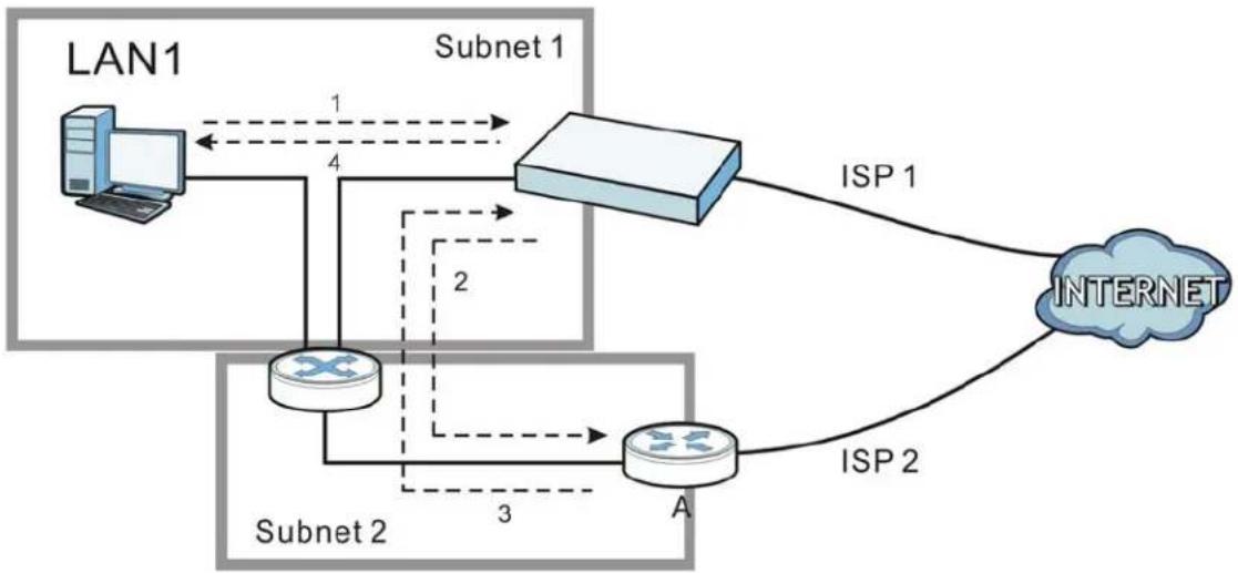
flowchart
graph TD
    LAN1["LAN1"] -->|1| Subnet1["Subnet 1"]
    Subnet1 -->|4| Subnet2["Subnet 2"]
    Subnet2 -->|3| A["Router A"]
    Subnet2 -->|2| Subnet1
    Subnet1 -->|ISP 1| INTERNET["INTERNET"]
    Subnet2 -->|ISP 2| INTERNET
25.2.1 Configuring the Firewall Screen
Click Configuration > Firewall to open the Firewall screen. Use this screen to enable or disable the firewall and asymmetrical routes, set a maximum number of sessions per host, and display the configured firewall rules. Specify from which zone packets come and to which zone packets travel to display only the rules specific to the selected direction. Note the following.
- Besides configuring the firewall, you also need to configure NAT rules to allow computers on the WAN to access LAN devices. See Chapter 15 on page 185 for more information.
- The UAG applies NAT (Destination NAT) settings before applying the firewall rules. So for example, if you configure a NAT entry that sends WAN traffic to a LAN IP address, when you configure a corresponding firewall rule to allow the traffic, you need to set the LAN IP address as the destination.
- The ordering of your rules is very important as rules are applied in sequence.
Figure 171 Configuration > Firewall
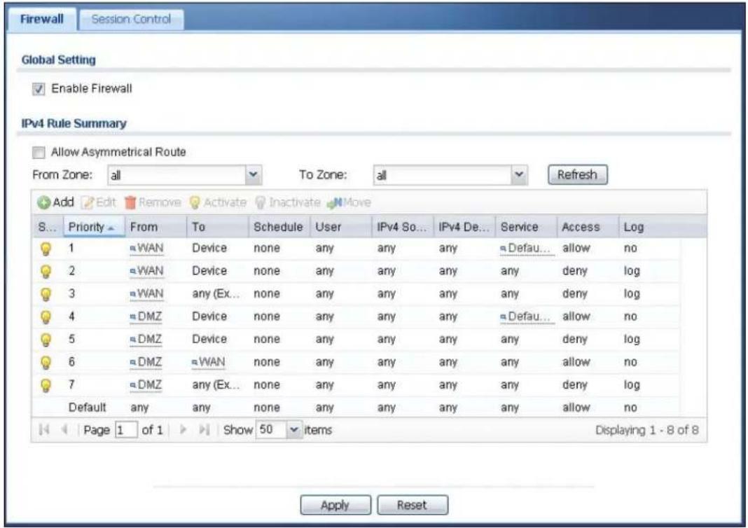
text_image
Firewall Session Control Global Setting Enable Firewall IPv4 Rule Summary Allow Asymmetrical Route From Zone: all To Zone: all Refresh Add Edit Remove Activate Inactivate Move S... Priority From To Schedule User IPv4 So... IPv4 De... Service Access Log 1 ≈ WAN Device none any any any any Defau... allow no 2 ≈ WAN Device none any any any any any deny log 3 ≈ WAN any (Ex... none any any any any any deny log 4 ≈ DMZ Device none any any any any Defau... allow no 5 ≈ DMZ Device none any any any any any deny log 6 ≈ DMZ ≈ WAN none any any any any allow no 7 ≈ DMZ any (Ex... none any any any deny log Default any any none any any any any allow no Page 1 of 1 Show 50 items Displaying 1 - 8 of 8 Apply ResetThe following table describes the labels in this screen.
Table 109 Configuration > Firewall
| LABEL DESCRIPTION | |
| General Settings | |
| Enable Firewall | Select this check box to activate the firewall. The UAG performs access control when the firewall is activated. |
| IPv4 Rule Summary | |
| Allow Asymmetrical Route | If an alternate gateway on the LAN has an IP address in the same subnet as the UAG's LAN IP address, return traffic may not go through the UAG. This is called an asymmetrical or "triangle" route. This causes the UAG to reset the connection, as the connection has not been acknowledged.Select this check box to have the UAG permit the use of asymmetrical route topology on the network (not reset the connection).Note: Allowing asymmetrical routes may let traffic from the WAN go directly to the LAN without passing through the UAG. A better solution is to use virtual interfaces to put the UAG and the backup gateway on separate subnets. |
| LABEL | DESCRIPTION |
| From Zone / To Zone | This is the direction of travel of packets. Select from which zone the packets come and to which zone they go.Firewall rules are grouped based on the direction of travel of packets to which they apply. For example, from LAN1 to LAN1 means packets traveling from a computer or subnet on the LAN1 to either another computer or subnet on the LAN1.From any displays all the firewall rules for traffic going to the selected To Zone.To any displays all the firewall rules for traffic coming from the selected From Zone.From any to any displays all of the firewall rules.To Device rules are for traffic that is destined for the UAG and control which computers can manage the UAG. |
| Add | Click this to create a new entry. Select an entry and click Add to create a new entry after the selected entry. |
| Edit | Double-click an entry or select it and click Edit to open a screen where you can modify the entry's settings. |
| Remove | To remove an entry, select it and click Remove. The UAG confirms you want to remove it before doing so. |
| Activate | To turn on an entry, select it and click Activate. |
| Inactivate | To turn off an entry, select it and click Inactivate. |
| Move | To change a rule's position in the numbered list, select the rule and click Move to display a field to type a number for where you want to put that rule and press [ENTER] to move the rule to the number that you typed.The ordering of your rules is important as they are applied in order of their numbering. |
| The following read-only fields summarize the rules you have created that apply to traffic traveling in the selected packet direction. | |
| Status This icon is | lit when the entry is active and dimmed when the entry is inactive. |
| Priority | This is the position of your firewall rule in the global rule list (including all through-UAG and to-UAG rules). The ordering of your rules is important as rules are applied in sequence.Default displays for the default firewall behavior that the UAG performs on traffic that does not match any other firewall rule. |
| FromTo | This is the direction of travel of packets to which the firewall rule applies. |
| Schedule | This field tells you the schedule object that the rule uses. none means the rule is active at all times if enabled. |
| User | This is the user name or user group name to which this firewall rule applies. |
| IPv4 Source | This displays the IPv4 source address object to which this firewall rule applies. |
| IPv4 Destination | This displays the IPv4 destination address object to which this firewall rule applies. |
| Service This displays the service object to which this firewall rule applies. | |
| Access | This field displays whether the firewall silently discards packets (deny), discards packets and sends a TCP reset packet to the sender (reject) or permits the passage of packets (allow). |
| Log | This field shows you whether a log (and alert) is created when packets match this rule or not. |
| Apply | Click Apply to save your changes back to the UAG. |
| Reset | Click Reset to return the screen to its last-saved settings. |
25.2.2 The Firewall Add/Edit Screen
In the Firewall screen, click the Add icon or select an entry and click the Edit icon to display the Add/ Edit Firewall Rule screen.
Figure 172 Configuration > Firewall > Add/Edit

text_image
Add Firewall Rule Create new Object Enable From: any To: any (Excluding Device) Description: (Optional) Schedule: none User: any Source: any Destination: any Service: any Access: allow Log: no OK CancelThe following table describes the labels in this screen.
Table 110 Configuration > Firewall > Add/Edit
| LABEL DESCRIPTION | |
| Create new Object | Use to configure any new settings objects that you need to use in this screen. |
| Enable Select this check box to activate the firewall rule. | |
| From To | For through-UAG rules, select the direction of travel of packets to which the rule applies.any means all interfaces.Device means packets destined for the UAG itself. |
| Description | Enter a descriptive name of up to 60 printable ASCII characters for the firewall rule. Spaces are allowed. |
| Schedule | Select a schedule that defines when the rule applies. Otherwise, selectnoneand the rule is always effective. |
| User This field is | not available when you are configuring a to-UAG rule.Select a user name or user group to which to apply the rule. The firewall rule is activated only when the specified user logs into the system and the rule will be disabled when the user logs out.Otherwise, selectanyand there is no need for user logging.Note: If you specified a source IP address (group) instead ofanyin the field below, the user's IP address should be within the IP address range. |
| Source | Select an IPv4 address or address group to apply an IPv4 rule to traffic coming from it.Selectanyto apply an IPv4 rule to all traffic coming from IPv4 addresses. |
| Destination | Select an IPv4 address or address group to apply an IPv4 rule to traffic going to it. Select any to apply an IPv4 rule to all traffic going to IPv4 addresses. |
| Service Select a service or service group from the drop-down list box. | |
| Access | Use the drop-down list box to select what the firewall is to do with packets that match this rule.Select deny to silently discard the packets without sending a TCP reset packet or an ICMP destination-unreachable message to the sender.Select reject to deny the packets and send a TCP reset packet to the sender. Any UDP packets are dropped without sending a response packet.Select allow to permit the passage of the packets. |
| Log | Select whether to have the UAG generate a log (log), log and alert (log alert) or not (no) when the rule is matched. See Chapter 42 on page 435 for more on logs. |
| OK | Click OK to save your customized settings and exit this screen. |
| Cancel | Click Cancel to exit this screen without saving. |
25.3 The Session Control Screen
Click Configuration > Firewall > Session Control to display the Firewall Session Control screen. Use this screen to limit the number of concurrent NAT/firewall sessions a client can use. You can apply a default limit for all users and individual limits for specific users, addresses, or both. The individual limit takes priority if you apply both.
Figure 173 Configuration > Firewall > Session Control
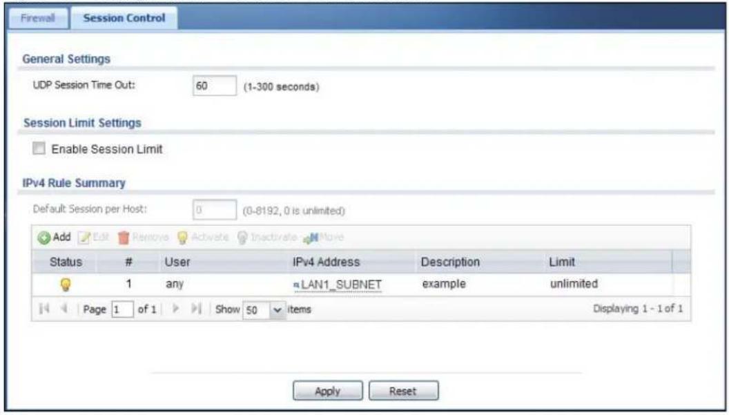
text_image
Firewall Session Control General Settings UDP Session Time Out: 60 (1-300 seconds) Session Limit Settings Enable Session Limit IPv4 Rule Summary Default Session per Host: 0 (0-8192, 0 is unlimited) Add Edit Remove Activate Inactivate Move Status # User IPv4 Address Description Limit 1 any LAN1_SUBNET example unlimited Page 1 of 1 Show 50 items Displaying 1 - 1 of 1 Apply ResetThe following table describes the labels in this screen.
Table 111 Configuration > Firewall > Session Control
| LABEL DESCRIPTION | |
| General Settings | |
| UDP Session Time Out | Set how many seconds (from 1 to 300) the UAG will allow a UDP session to remain idle (without UDP traffic) before closing it. |
| Session Limit Settings | |
| Enable Session limit | Select this check box to control the number of concurrent sessions hosts can have. |
| IPv4 Rule Summary | This table lists the rules for limiting the number of concurrent sessions hosts can have. |
| Default Session per Host | This field is configurable only when you enable session limit.Use this field to set a common limit to the number of concurrent NAT/firewall sessions each client computer can have.If only a few clients use peer to peer applications, you can raise this number to improve their performance. With heavy peer to peer application use, lower this number to ensure no single client uses too many of the available NAT sessions.Create rules below to apply other limits for specific users or addresses. |
| Add | Click this to create a new entry. Select an entry and click Add to create a new entry after the selected entry. |
| Edit | Double-click an entry or select it and click Edit to open a screen where you can modify the entry's settings. |
| Remove | To remove an entry, select it and click Remove. The UAG confirms you want to remove it before doing so. |
| Activate | To turn on an entry, select it and click Activate. |
| Inactivate | To turn off an entry, select it and click Inactivate. |
| Move | To change a rule's position in the numbered list, select the rule and click Move to display a field to type a number for where you want to put that rule and press [ENTER] to move the rule to the number that you typed.The ordering of your rules is important as they are applied in order of their numbering. |
| Status | This icon is lit when the entry is active and dimmed when the entry is inactive. |
| # | This is the index number of a session limit rule. It is not associated with a specific rule. |
| User This is the user name or user group name to which this session limit rule applies. | |
| IPv4 Address This is the IPv4 address object to which this session limit rule applies. | |
| Description This is the information configured to help you identify the rule. | |
| Limit | This is how many concurrent sessions this user or address is allowed to have. |
| Apply | Click Apply to save your changes back to the UAG. |
| Reset | Click Reset to return the screen to its last-saved settings. |
25.3.1 The Session Control Add/Edit Screen
Click Configuration > Firewall > Session Control, and then click the Add icon or select an entry and click the Edit icon to display the Firewall Session Control Add/ Edit screen. Use this screen to configure rules that define a session limit for specific users or addresses.
Figure 174 Configuration > Firewall > Session Control > Add/Edit
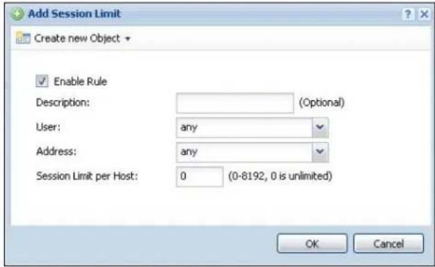
text_image
Add Session Limit Create new Object Enable Rule Description: (Optional) User: any Address: any Session Limit per Host: 0 (0-8192, 0 is unlimited) OK CancelThe following table describes the labels in this screen.
Table 112 Configuration > Firewall > Session Control > Add/Edit
| LABEL DESCRIPTION | |
| Create new Object | Use to configure any new settings objects that you need to use in this screen. |
| Enable Rule Select | this check box to turn on this session limit rule. |
| Description | Enter information to help you identify this rule. Use up to 60 printable ASCII characters. Spaces are allowed. |
| User | Select a user name or user group to which to apply the rule. The rule is activated only when the specified user logs into the system and the rule will be disabled when the user logs out.Otherwise, selectanyand there is no need for user logging.Note: If you specified an IP address (or address group) instead ofanyin the field below, the user's IP address should be within the IP address range. |
| Address | Select the IPv4 source address or address group to which this rule applies. Selectanyto apply the rule to all IPv4 source addresses. |
| Session Limit per Host | Use this field to set a limit to the number of concurrent NAT/firewall sessions this rule's users or addresses can have.For this rule's users and addresses, this setting overrides theDefault Session per Host setting in the generalFirewall Session Controlscreen. |
| OK | ClickOKto save your customized settings and exit this screen. |
| Cancel | ClickCancelto exit this screen without saving. |
25.4 Firewall Rule Configuration Example
The following Internet firewall rule example allows Doom players from the WAN to IP addresses 172.16.1.10 through 172.16.1.15 (Dest_1) on the LAN.
1 Click Configuration > Firewall. In the summary of firewall rules click Add to configure a new first entry. The sequence (priority) of the rules is important since they are applied in order.
Figure 175 Firewall Example: Firewall Screen
2 At the top of the screen, click Create new Object > Address to configure an address object. Configure it as follows and click OK.
Figure 176 Firewall Example: Create an Address Object
3 Click Create new Object > Service to configure a service object for Doom (UDP port 666). Configure it as follows and click OK.
Figure 177 Firewall Example: Create a Service Object
4 Select From WAN and To LAN and enter a name for the firewall rule.
Select Dest_1 for the Destination and Doom as the Service. Enter a description and configure the rest of the screen as follows. Click OK when you are done.
Figure 178 Firewall Example: Edit a Firewall Rule
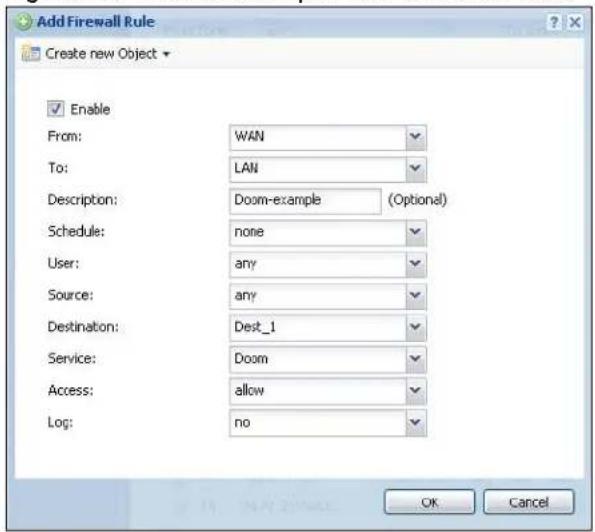
text_image
Add Firewall Rule Create new Object Enable From: WAN To: LAN Description: Doom-example (Optional) Schedule: none User: any Source: any Destination: Dest_1 Service: Doom Access: allow Log: no OK Cancel5 The firewall rule appears in the firewall rule summary.
Figure 179 Firewall Example: Doom Rule in Summary
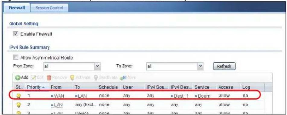
text_image
Firewall Session Control Global Setting Enable Firewall IPv4 Rule Summary Allow Asymmetrical Route From Zone: all To Zone: all Refresh Add Edit Remove Activate Inactivate More St. Priority From To Schedule User IPv4 Sou... IPv4 Des... Service Access Log 1 ≈ WAN ≈ LAN none any any ≈ Dest 1 ≈ Doom allow no 2 ≈ LAN any (Excl... none any any any any allow no 3 ≈ LAN Device none any any any any allow no25.5 Firewall Rule Example Applications
Suppose you decide to block LAN users from using IRC (Internet Relay Chat) through the Internet. To do this, you would configure a LAN to WAN firewall rule that blocks IRC traffic from any source IP address from going to any destination address. You do not need to specify a schedule since you need the firewall rule to always be in effect. The following figure shows the results of this rule.
Figure 180 Blocking All LAN to WAN IRC Traffic Example
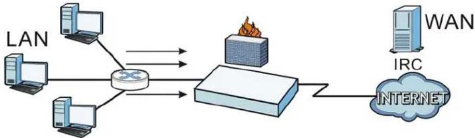
flowchart
graph LR
    LAN --> Router
    Router --> LAN
    Router --> LAN
    LAN --> Internet
    Internet --> WAN
    LAN --> Internet
    Router --> Router
    Router --> Router
    Router --> Router
    Router --> Router
    Router --> Router
    Router --> Router
    Router --> Router
    Router --> Router
    Router --> Router
    Router --> Router
    Router --> Router
    Router --> Router
    Router --> Router
    Router --> Router
    Router --> Router
    Router --> Router
    Router --> Router
    Router --> Router
    Router --> Router
    Router --> Router
    Router -->Router
Your firewall would have the following rules.
Table 113 Blocking All LAN to WAN IRC Traffic Example
| # | USER | SOURCE | DESTINATION | SCHEDULE | SERVICE | ACTION |
| 1 | Any Any Any Any | IRC | Deny | |||
| 2 | Any Any Any Any | Any | Allow |
- The first row blocks LAN access to the IRC service on the WAN.
- The second row is the firewall's default policy that allows all LAN1 to WAN traffic.
The UAG applies the firewall rules in order. So for this example, when the UAG receives traffic from the LAN, it checks it against the first rule. If the traffic matches (if it is IRC traffic) the firewall takes the action in the rule (drop) and stops checking the firewall rules. Any traffic that does not match the first firewall rule will match the second rule and the UAG forwards it.
Now suppose you need to let the CEO use IRC. You configure a LAN1 to WAN firewall rule that allows IRC traffic from the IP address of the CEO's computer. You can also configure a LAN to WAN rule that allows IRC traffic from any computer through which the CEO logs into the UAG with his/her user name. In order to make sure that the CEO's computer always uses the same IP address, make sure it either:
- Has a static IP address, or
- You configure a static DHCP entry for it so the UAG always assigns it the same IP address (see DHCP Settings on page 155 for information on DHCP).
Now you configure a LAN1 to WAN firewall rule that allows IRC traffic from the IP address of the CEO's computer (172.16.1.7 for example) to go to any destination address. You do not need to specify a schedule since you want the firewall rule to always be in effect. The following figure shows the results of your two custom rules.
Figure 181 Limited LAN to WAN IRC Traffic Example

flowchart
graph TD
    A["LAN1"] --> B["Router"]
    C["CEO 172.16.1.7"] --> B
    D["Computer"] --> B
    E["Computer"] --> B
    F["Computer"] --> B
    G["Computer"] --> B
    H["WAN"] --> I["IRC"]
    J["INTERNET"] --> K["Router"]
    B <--> K
    style B fill:#f9f,stroke:#333
    style K fill:#ccf,stroke:#333
Your firewall would have the following configuration.
Table 114 Limited LAN1 to WAN IRC Traffic Example 1
| # | USER | SOURCE | DESTINATION | SCHEDULE | SERVICE | ACTION |
| 1 Any 17 | 2.16.1.7 | Any Any IRC | Allow | |||
| 2 | Any | Any | Any | Any | IRC | Deny |
| 3 | Any | Any | Any | Any | Any | Allow |
- The first row allows the LAN1 computer at IP address 172.16.1.7 to access the IRC service on the WAN.
- The second row blocks LAN1 access to the IRC service on the WAN.
- The third row is the firewall's default policy of allowing all traffic from the LAN1 to go to the WAN.
Alternatively, you configure a LAN1 to WAN rule with the CEO's user name (say CEO) to allow IRC traffic from any source IP address to go to any destination address.
Your firewall would have the following configuration.
Table 115 Limited LAN1 to WAN IRC Traffic Example 2
| # | USER | SOURCE | DESTINATION | SCHEDULE | SERVICE | ACTION |
| 1 | CEO | Any | Any | Any | IRC | Allow |
| 2 | Any | Any | Any | Any | IRC | Deny |
| 3 | Any | Any | Any | Any | Any | Allow |
- The first row allows any LAN1 computer to access the IRC service on the WAN by logging into the UAG with the CEO's user name.
- The second row blocks LAN1 access to the IRC service on the WAN.
- The third row is the firewall's default policy of allowing all traffic from the LAN1 to go to the WAN.
The rule for the CEO must come before the rule that blocks all LAN1 to WAN IRC traffic. If the rule that blocks all LAN1 to WAN IRC traffic came first, the CEO's IRC traffic would match that rule and the UAG would drop it and not check any other firewall rules.
26.1 Overview
You can use the built-in billing function to setup billing profiles. A billing profile describes how to charge users. This chapter also shows you how to select an accounting method, configure a discount price plan or use an online payment service by credit card.
26.1.1 What You Can Do in this Chapter
- Use the General screen (see Section 26.2 on page 260) to configure the general billing settings, such as the accounting method, currency unit and the SSID profiles to which the settings are applied.
- Use the Billing Profile screen (see Section 26.3 on page 261) to configure the billing profiles for the web-based account generator and each button on the connected statement printer.
- Use the Discount screen (see Section 26.4 on page 269) to enable and configure discount price plans.
- Use the Payment Service screen (see Section 26.5 on page 270) to enable online payment service and configure the service pages.
26.1.2 What You Need to Know
Accumulation Accounting Method
The accumulation accounting method allows multiple re-logins until the allocated time period or until the user account is expired. The UAG accounts the time that the user is logged in for Internet access.
Time-to-finish Accounting Method
The time-to-finish accounting method is good for one-time logins. Once a user logs in, the UAG stores the IP address of the user's computer for the duration of the time allocated. Thus the user does not have to enter the user name and password again for re-login within the allocated time. Once activated, the user account is valid until the allocated time is reached even if the user disconnects Internet access for a certain period within the allocated time. For example, Joe purchases a one-hour time-to-finish account. He starts using the Internet for the first 20 minutes and then disconnects his Internet access to go to a 20-minute meeting. After the meeting, he only has 20 minutes left on his account.
26.2 The General Screen
Use this screen to configure the general billing settings, such as the accounting method, currency unit and the SSID profiles to which the settings are applied. Click Configuration > Billing > General to open the following screen.
Figure 182 Configuration > Billing > General
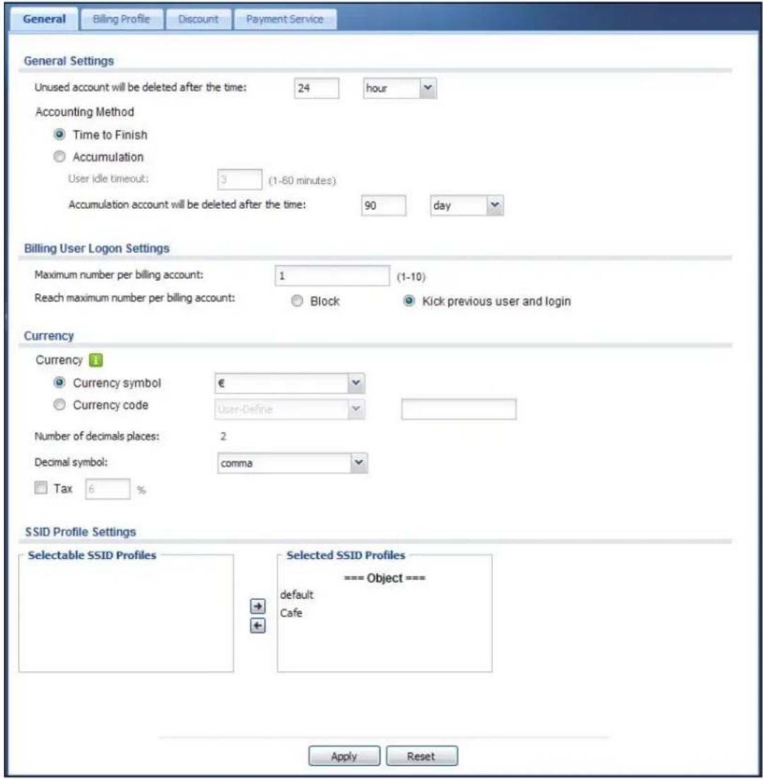
text_image
General Billing Profile Discount Payment Service General Settings Unused account will be deleted after the time: 24 hour Accounting Method Time to Finish Accumulation User idle timeout: 3 (1-60 minutes) Accumulation account will be deleted after the time: 90 day Billing User Logon Settings Maximum number per billing account: 1 (1-10) Reach maximum number per billing account: Block Kick previous user and login Currency Currency 1 Currency symbol € Currency code User-Define Number of decimals places: 2 Decimal symbol: comma Tax 6 % SSID Profile Settings Selectable SSID Profiles Selected SSID Profiles === Object === default Cafe Apply ResetThe following table describes the labels in this screen.
Table 116 Configuration > Billing > General
| LABEL DESCRIPTION | |
| General Settings | |
| Unused account will be deleted after the time: | Enter the number and select a time unit from the drop-down list box to specify how long to wait before the UAG deletes an account that has not been used. |
| Accounting Method | Select Time to Finish to allow each user a one-time login. Once the user logs in, the system starts counting down the pre-defined usage even if the user stops the Internet access before the time period is finished. If a user disconnects and reconnects before the allocated time expires, the user does not have to enter the user name and password to access the Internet again.SelectAccumulationto allow each user multiple re-login until the time allocated is used up. The UAG accounts the time that the user is logged in for Internet access. |
| User idle timeout | The UAG automatically disconnects a computer from the network after a period of inactivity. The user may need to enter the username and password again before access to the network is allowed.If you selectAccumulation, specify the idle timeout between 1 and 60 minutes. |
| Accumulation account will be deleted after the time: | Enter the number and select a time unit from the drop-down list box to specify how long to wait before the UAG deletes an idle account.This is for use with accumulation accounting. |
| Billing User Logon Settings | |
| Maximum number per billing account | Enter the maximum number of the users that are allowed to log in with the same account. |
| Reach maximum number per billing account | SelectBlockto stop new users from logging in when theMaximum number per billing accountis reached.SelectKick previous user and loginto disassociate the first user that logged in and allow new user to log in when theMaximum number per billing accountis reached. |
| Currency Select the appropriate currency symbol or currency unit.If you setCurrency code to User-Define, enter a three-letter alphabetic code manually. | |
| Number of decimals places | This shows the number of decimal places to be used for billing. |
| Decimal symbol | Select whether you would like to use a dot (.) or a comma (,) for the decimal point. |
| Tax Select this option to charge sales tax for the account. Enter the tax rate (a 6% sales tax is entered as 6). | |
| SSID Profile Settings | TheSelectable SSID Profileslist displays the name(s) of the SSID profile(s) to which you can apply the general billing settings.To apply settings to an SSID profile, you can double-click a single entry to move it or use the [Shift] or [Ctrl] key to select multiple entries and click the right arrow button to add to theSelected SSID Profileslist. To remove an SSID profile, select the name(s) in theSelected SSID Profileslist and click the left arrow button. |
| Apply Click this button to save your changes to the UAG. | |
| Reset Click this button to return the screen to its last-saved settings. | |
26.3 The Billing Profile Screen
Use this screen to configure the billing profiles that defines the maximum Internet access time and charge per time unit. Click Configuration > Billing > Billing Profile to open the following screen.
Figure 183 Configuration > Billing > Billing Profile

text_image
General Billing Profile Discount Payment Service Account Generator Settings Button A: billing_30mins Button B: billing_30mins Button C: billing_30mins Preview Billing Profile Add Edit Remove Activate InactivateStatus Name Time Period Price
1 billing_30mins 30 minute €2,00 2 billing_1hour 1 hour €4,00 Page 1 of 1 Show 50 items Displaying 1 - 2 of 2 Apply ResetThe following table describes the labels in this screen.
Table 117 Configuration > Billing > Billing Profile
| LABEL DESCRIPTION | |
| Account Generator Settings | |
| Button A ~ C | Select a billing profile for each button of the web-based account generator. The buttons correspond to the buttons on a connected statement printer. |
| Preview | Click this button to open the Account Generator screen, where you can generate a dynamic guest account and print the account information using a statement printer connected to the UAG (see Section 26.3.1 on page 263 for more information). |
| Billing Profile | |
| Add Click this to create a new entry. | |
| Edit | Double-click an entry or select it and click Edit to open a screen where you can modify the entry's settings. |
| Remove | To remove an entry, select it and click Remove. The UAG confirms you want to remove it before doing so. |
| Activate | To turn on an entry, select it and click Activate. |
| Inactivate | To turn off an entry, select it and click Inactivate. |
| # | This field is a sequential value, and it is not associated with a specific entry. |
| Status This icon is lit when the entry is active and dimmed when the entry is inactive. | |
| Name This field displays the descriptive profile name for this entry. | |
| Time Period This field displays the duration of the billing period. | |
| Price This field displays each profile's price per time unit. | |
| Apply | Click this button to save your changes to the UAG. |
| Reset | Click this button to return the screen to its last-saved settings. |
26.3.1 The Account Generator Screen
The Account Generator screen allows you to automatically create dynamic guest accounts (see Section 7.11 on page 92 and Dynamic-Guest Accounts on page 326 for more information on dynamic guest accounts).
Click Configuration > Billing > Billing Profile and then the Preview button to open this screen. You can also open this screen by logging into the Web Configurator with the guest-manager account.
Figure 184 Account Generator
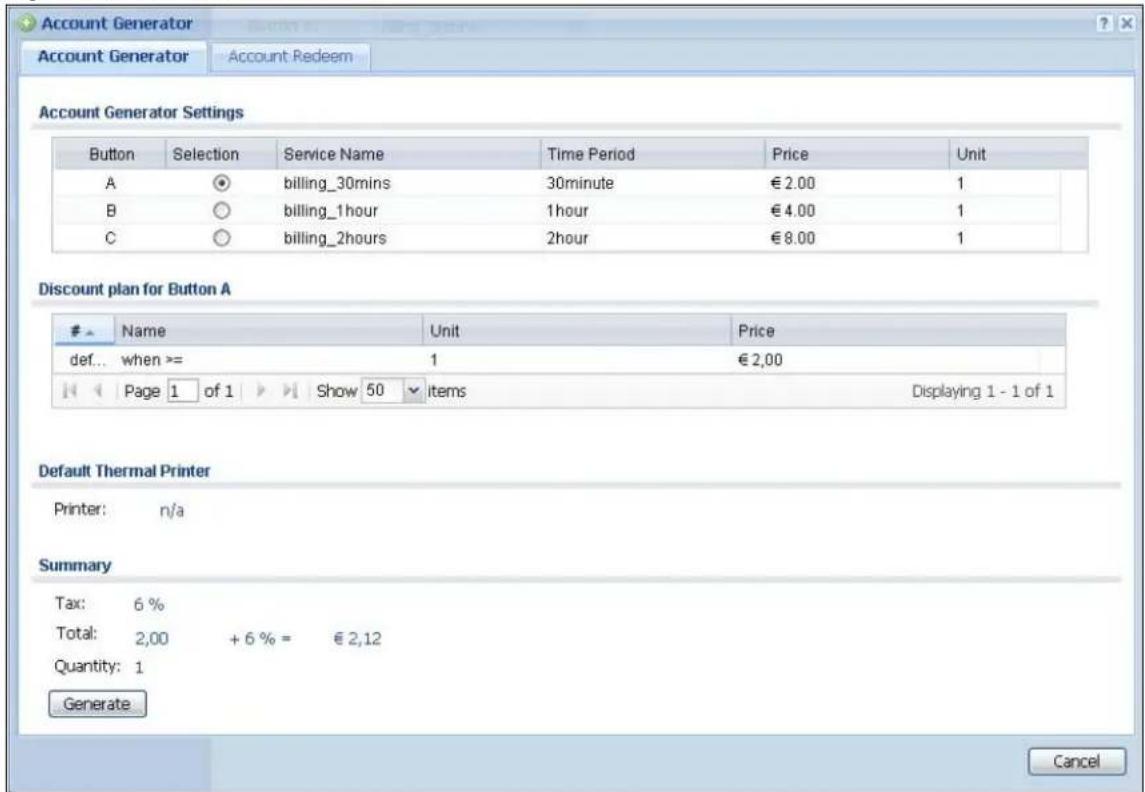
text_image
Account Generator Account Generator Account Redeem Account Generator Settings Button Selection Service Name Time Period Price Unit A ○ billing_30mins 30minute € 2.00 1 B ○ billing_1hour 1hour € 4.00 1 C ○ billing_2hours 2hour € 8.00 1 Discount plan for Button AName Unit Price
def... when >= 1 € 2,00 Page 1 of 1 Show 50 items Displaying 1 - 1 of 1 Default Thermal Printer Printer: n/a Summary Tax: 6 % Total: 2,00 + 6 % = € 2,12 Quantity: 1 Generate CancelThe following table describes the labels in this screen.
Table 118 Account Generator
| LABEL DESCRIPTION | |
| Account Generator Settings | |
| Button | Each button represents a billing profile that defines maximum Internet access time and charge per time unit. |
| Selection Select a | button for new account. |
| Service Name This field displays the descriptive name of the billing profile. | |
| Time Period This field displays the duration of the billing period. | |
| Price This field displays each profile's price per time unit. | |
| Unit | This field displays how many units of billing period to be charged for new account. Click to select a new number. |
| Discount plan for Button x | This section displays only when you enable the discount price plan in the Billing > Discount screen. |
| # This is the number of each discount level.The default (first) level cannot be edited or deleted. It is created automatically according to the billing profile of the button you select. | |
| Name This field displays the conditions of each discount level. | |
| Unit | This field displays the duration of the billing period that should be reached before the UAG charges users at this level. |
| Price This field displays the price per time unit for each level. | |
| Default Thermal Printer | This displays the information of the printer that is attached to the UAG. It displays n/ a if there is no printer attached. |
| Summary | |
| Tax This shows the tax rate. | |
| Total This shows the total price for the account. | |
| Quantity This shows the number of account to be created. | |
| Generate | Click Generate to generate an account based on the billing settings you configure for the selected button in the Billing Profile screen. A window displays showing the SMS message and/or a printout preview of the account generated. |
| Cancel | Click Cancel to exit this screen without saving. |
| Logout | Click Logout to log out of the web configurator. This button is available only when you open this screen by logging in with the guest-manager account. |
The following figure shows an example SMS message with account information. The SMS screen displays only when you enable SMS in the Configuration > SMS screen. You can enter the user's
mobile phone number and click Send SMS to send the account information in an SMS text message to the user's mobile phone. Close this window when you are finished viewing it.

text_image
Account Generator SMS Printer SMS Content Username:xtesm7 Password:ta67ut Activate account before 2013-05-10 08:38 Send SMS Country Code: 886 Mobile Number: 0912345678 Example: [886][0910123456] (for Taiwan) Send SMS CancelThe following figure shows a printout preview example. Close this window when you are finished viewing it.

text_image
Account Generator SMS Printer Welcome! Hotspot internet access service Username: uqw8a5 Password: 258k93 Billing: accumulation Service: billing_30mins Unit: 2 Time Period: 60 minutes Total: $ 4 Tax: 6.0% Grand Total: $ 4,24 Wlan1 Wlan2 ESSID: none Security: none Key: none Printout time: 2013-05-09 07:26 Please activate your account before 2013-05-10 07:27 Thank you very much! 4.24 Cancel26.3.2 The Account Redeem Screen
The Account Redeem screen allows you to send SMS messages for certain accounts. Click the Account Redeem tab in the Account Generator screen to open this screen.
Figure 185 Account Redeem
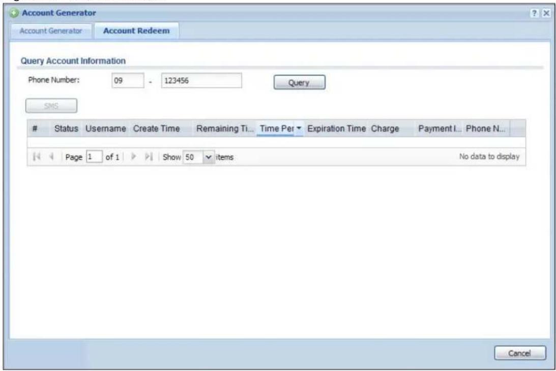
text_image
Account Generator Account Generator Account Redeem Query Account Information Phone Number: 09 - 123456 Query SMSStatus Username Create Time Remaining Ti... Time Per Expiration Time Charge Payment I... Phone N...
Page 1 of 1 Show 50 items No data to display CancelThe following table describes the labels in this screen.
Table 119 Account Redeem
| LABEL DESCRIPTION | |
| Query Account Information | |
| Phone Number | Enter the country code and mobile phone number and click Query to display only the account(S) that has the specified phone number. |
| SMS Click this button | to send text messages for the accounts in the list below.You can use this button only when SMS is enabled and there is at least one account in the list. |
| # This is the index | number of the dynamic guest account in the list. |
| Status | This field displays whether an account expires or not. |
| Username This field | d displays the user name of the account. |
| Create Time This field | displays when the account was created. |
| Remaining Time | This field displays the amount of Internet access time remaining for each account. |
| Time Period This field | displays the total account of time the account can use to access the Internet through the UAG. |
| Expiration Time This field | displays the date and time the account becomes invalid.Note: Once the time allocated to a dynamic account is used up or a dynamic account remains un-used after the expiration time, the account is deleted from the account list. |
| Charge This field displays the total cost of the account. | |
| Payment Info This field | displays the method of payment for each account. |
| Phone Num | This field displays the mobile phone number for the account. |
| Cancel | Click Cancel to exit this screen without saving. |
| Logout | Click Logout to log out of the web configurator. This button is available only when you open this screen by logging in with the guest-manager account. |
26.3.3 The Billing Profile Add/Edit Screen
The Billing Profile Add/ Edit screen allows you to create a new billing profile or edit an existing one. Click Configuration > Billing > Billing Profile and then click the Add icon or select an entry and click the Edit icon to open this screen.
Figure 186 Configuration > Billing > Billing Profile > Add/Edit
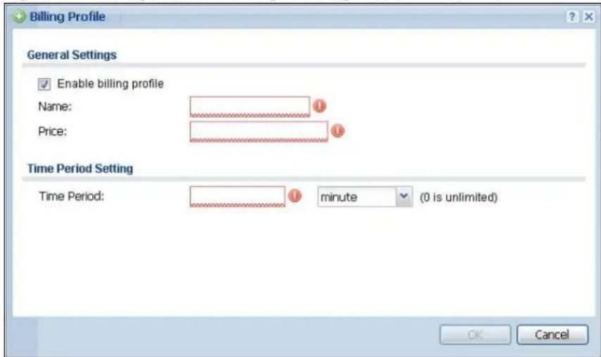
text_image
Billing Profile General Settings Enable billing profile Name: Price: Time Period Setting Time Period: minute (0 is unlimited) OK CancelThe following table describes the labels in this screen.
Table 120 Configuration > Billing > Billing Profile > Add/Edit
| LABEL DESCRIPTION | |
| Enable billing profile | Select this option to activate the profile. |
| Name Enter a name for the billing profile.You can use up to 31 alphanumeric characters (A-Z, a-z, 0-9) and underscores (_). Spaces are not allowed. The first character must be a letter. | |
| Price Define each profile's price, up to 999999.99, per time unit. | |
| Time Period | Set the duration of the billing period. When this period expires, the user's access will be stopped.Select a time period (minute, hour, or day) and enter the time unit to define each profile's maximum Internet access time. |
| OK | Click OK to save your changes back to the UAG. |
| Cancel | Click Cancel to exit this screen without saving. |
26.4 The Discount Screen
Use this screen to configure a custom discount pricing plan. This is useful for providing reduced rates for purchases of longer periods of time. You can charge higher rates per unit at lower levels (fewer units purchased) and lower rates per unit at higher levels (more units purchased). Click Configuration > Billing > Discount to open the following screen.
Note: The discount price plan does not apply to users who purchase access time online with a credit card.
Figure 187 Configuration > Billing > Discount
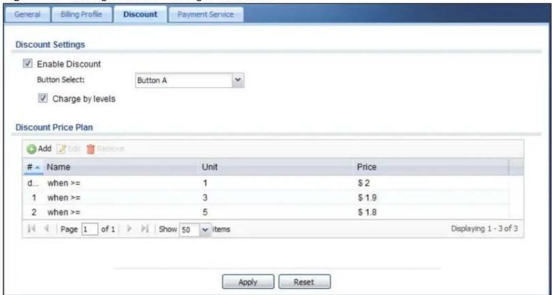
text_image
General Billing Profile Discount Payment Service Discount Settings Enable Discount Button Select: Button A Charge by levels Discount Price Plan Add Edit RemoveName Unit Price
d... when >= 1 $2 1 when >= 3 $1.9 2 when >= 5 $1.8 Page 1 of 1 Show 50 items Displaying 1 - 3 of 3 Apply ResetThe following table describes the labels in this screen.
Table 121 Configuration > Billing > Discount
| LABEL DESCRIPTION | |
| Discount Settings | |
| Enable Discount Select the check box to activate the discount price plan. | |
| Button Select Select a button from the drop-down list box to assign the base charge. | |
| Charge by levels | Select this to charge the rate at each successive level from the first level (most expensive per unit) to the highest level (least expensive per unit) that the total purchase reaches.Otherwise, deselect this to charge all of the user's time units only at the highest level (least expensive) that their total purchase reaches. |
| Discount Price Plan | |
| Add Click this to create a new entry. | |
| Edit | Double-click an entry or select it and click Edit to open a screen where you can modify the entry's settings. |
| Remove | To remove an entry, select it and click Remove. The UAG confirms you want to remove it before doing so. |
| # This is the number of each discount level.The default (first) level cannot be edited or deleted. It is created automatically according to the billing profile of the button you select. | |
| Name This field displays the conditions of each discount level. | |
| Unit | This field displays the duration of the billing period that should be reached before the UAG charges users at this level. |
| Price This field displays the price per time unit for each level. | |
| Apply Click this button to save your changes to the UAG. | |
| Reset Click this button to return the screen to its last-saved settings. | |
26.4.1 The Discount Add/Edit Screen
The Discount Add/ Edit screen allows you to create a new discount level or edit an existing one. Click Configuration > Billing > Discount and then click the Add icon or select an entry and click the Edit icon to open this screen.
Figure 188 Configuration > Billing > Discount > Add/Edit

text_image
Add Discount Settings Name: when >= Unit: Price:The following table describes the labels in this screen.
Table 122 Configuration > Billing > Discount > Add/Edit
| LABEL DESCRIPTION | |
| Name This field displays the conditions of each discount level. | |
| Unit | Set the duration of the billing period that should be reached before the UAG charges users at this level. |
| Price Define this level's charge per time unit. | |
| OK | Click OK to save your changes back to the UAG. |
| Cancel | Click Cancel to exit this screen without saving. |
26.5 The Payment Service General Screen
Use this screen to use a credit card service to authorize, process, and manage credit card transactions directly through the Internet. You must register with the supported credit card service
before you can configure the UAG to handle credit card transactions. Click Configuration > Billing > Payment Service to open the following screen.
Figure 189 Configuration > Billing > Payment Service > General

text_image
General Billing Profile Discount Payment Service General Custom Service General Setting Enable Payment Service Payment Provider Selection Account: Currency: Euro(EUR) Identity Token: Payment Gateway: https://www.paypal.com/cgi-bin/webscr Account Delivery Method Delivery Method: On-Screen and SMS Apply ResetThe following table describes the labels in this screen.
Table 123 Configuration > Billing > Payment Service > General
| LABEL DESCRIPTION | |
| General Setting | |
| Enable Payment Service | Select the check box to use PayPal to authorize credit card payments.Note: After you set up web authentication policies and enable the online payment service on the UAG, a link displays in the login screen when users try to access the Internet. The link redirects users to a screen where they can make online payments by credit card to purchase access time and get dynamic guest account information. |
| Payment Provider Selection | |
| Account | You should already have a PayPal account to receive credit card payments.Enter your PayPal account name. |
| Currency | Select the currency in which payments are made. The available options depend on currencies that PayPal supports. |
| Identity Token | Enter the ID token provided to you by PayPal after successfully applying for your PayPal account. |
| Payment Gateway | Enter the address of the PayPal gateway provided to you by PayPal after applying for your PayPal account. |
| Account Delivery Method | |
| Delivery Method | Specify how the UAG provides dynamic guest account information after the user's online payment is done.Select On-Screen to display the user account information in the web screen.Select SMS to use Short Message Service (SMS) to send account information in a text message to the user's mobile device.Select On-Screen and SMS to provide the account information both in the web screen and via SMS text messages.Note: You should have enabled SMS in theConfiguration > SMSscreen to send text messages to the user's mobile device. |
| Apply Click this button to save your changes to the UAG. | |
| Reset Click this button to return the screen to its last-saved settings. | |
26.5.1 The Payment Service Custom Service Screen
Use this screen to customize the online payment service pages that displays after an unauthorized user click the link in the Web Configurator login screen to purchase access time. Click Configuration > Billing > Payment Service > Custom Service to open the following screen.
Figure 190 Configuration > Billing > Payment Service > Custom Service

text_image
General Biting Profile Discount Payment Service General Custom Service Select Type Use Default Page Use Customized Page Customized Profile Selection Page Selection Messages: Please choose the service plan from the following profile task Welcome Please choose this service plan from the following profile table.Service Name Usage Time Charge Quantity
1 ○ AAA 2 hour $23 1 2 ○ AAA 2 hour $23 1 3 ○ AAA 2 hour $23 1 4 ○ AAA 2 hour $23 1 5 ○ AAA 2 hour $23 1 6 ○ AAA 2 hour $23 1 OK Customized Successfully Page Successfully Message: You may now use the internet. Notification Message: IMPORTANT MAKE a note for your case-sensitive Notification Color: red Color (CSS color code) Account Messages: This is your account information, please keep this f Day Time: dd/mm/yyyy 24 hour Welcome You may now use the internet. IMPORTANT MAKE a note for your case-sensitive username and password for logging later. This will be your only opportunity to do so. This is your account information, please keep this for your internet service. Your username is XXXX Your password is XXXX Your time period is 0 days, 00 hour 30 minutes Please activate your account before 28.03.2012, 23:00:00 Login Now Customized Fail Page Failed Message: Sorry! We can't handle your payment transaction at this time Welcome Sorry! We can't handle your payment transaction at this time. Go to PayPal and check your account. OK Customized SMS Page 1 Information Messages: Please check your mobile phone for the account information. Welcome Please check your mobile phone for the account information. OK Apply ResetThe following table describes the labels in this screen.
Table 124 Configuration > Billing > Payment Service > Custom Service
| LABEL DESCRIPTION | |
| Select Type | |
| Use Default Page | Select this to use the default online payment service page built into the device. If you later create a custom online payment service page, you can still return to the UAG's default page as it is saved indefinitely. |
| Use Customized Page | Select this to use a custom online payment service page instead of the default one built into the UAG. Once this option is selected, the custom page controls below become active. |
| Customized Profile Selection Page | |
| Selection Message | Enter a note to display in the first welcome page that allows users to choose a billing period they want. Use up to 1024 printable ASCII characters. Spaces are allowed. |
| Customized Successfully Page | |
| Successfully Message | Enter a note to display in the second page after the user's online payment is made successfully. Use up to 1024 printable ASCII characters. Spaces are allowed. |
| Notification Message | Enter the important information you want to display. Use up to 1024 printable ASCII characters. Spaces are allowed. |
| Notification Color | Specify the font color of the important information. You can use the color palette chooser, or enter a color value of your own. |
| Account Message | Enter a note to display above the user account information. Use up to 1024 printable ASCII characters. Spaces are allowed. |
| Day Time | Select the format in which you want to display the date and how long an account is allowed to stay un-used before it expires. |
| Customized Fail Page | |
| Failed Message | Enter a note to display when the user's online payment failed. Use up to 1024 printable ASCII characters. Spaces are allowed. |
| Customized SMS Page | |
| Information Message | Enter a note to display when you set the UAG to send account information via SMS text messages. Use up to 1024 printable ASCII characters. Spaces are allowed. |
| Apply Click this button to save your changes to the UAG. | |
| Reset Click this button to return the screen to its last-saved settings. | |
27.1 Overview
You can create dynamic guest accounts and print guest account information by pressing the button on an external statement printer, such as SP350E.
Make sure that the printer is connected to the appropriate power and the UAG, and that there is printing paper in the printer. Refer to the printer's documentation for details.
27.1.1 What You Can Do in this Chapter
- Use the General screen (see Section 27.2 on page 275) to configure the printer list and enable printer management.
- Use the Printout Configuration screen (see Section 27.3 on page 277) to customize the account printout.
27.2 The General Screen
Use this screen to configure a printer list and allow the UAG to monitor the printer status. Click Configuration > Printer Manager > General to open the following screen.
Figure 191 Configuration > Printer Manager > General

text_image
General Printout Configuration General Setting Enable Printer Manager Printer Settings Port: 9100 Encryption Secret Key: (4 characters) Printout Number of Copies: 1 Printer List Note: If you want to configure printer button, please go to Billing Profile. Add Edit Remove Activate InactivateStatus IPv4 Address Description
1 172.17.1.1 new create Page 1 of 1 Show 50 items Displaying 1 - 1 of 1 Printer Firmware Information Current Version: SP350E-V1.01 Apply ResetThe following table describes the labels in this screen.
Table 125 Configuration > Printer Manager > General
| LABEL DESCRIPTION | |
| General Setting | |
| Enable Printer Manager | Select the check box to allow the UAG to manage and monitor the printer status. |
| Printer Settings | |
| Port | Enter the number of port on which the UAG sends data to the printer for it to print. |
| Encryption | Select the check box to turn on data encryption. Data transmitted between the UAG and the printer will be encrypted with a secret key |
| Secret Key | Enter four alphanumeric characters (A-Z, a-z, 0-9) to specify a key for data encryption. |
| Printout | |
| Number of Copies | Select how many copies of subscriber statements you want to print (1 is the default). |
| Printer List | Use this section to add the printer(s) that can be managed by the UAG. |
| Add Click this to create a new entry. | |
| Edit | Double-click an entry or select it and click Edit to open a screen where you can modify the entry's settings. |
| Remove | To remove an entry, select it and click Remove. The UAG confirms you want to remove it before doing so. |
| Activate | To turn on an entry, select it and click Activate. |
| Inactivate | To turn off an entry, select it and click Inactivate. |
| # This field is a sequential value, and it is not associated with any entry. | |
| Status This icon is lit when the entry is active and dimmed when the entry is inactive. | |
| IPv4 Address This field displays the IP address of the printer. | |
| Description This field displays the descriptive name for the printer. | |
| Printer Firmware Information | |
| Current Version | This is the version of the printer firmware currently uploaded to the UAG. The UAG automatically installs it in the connected printers to make sure the printers are upgraded to the same version. |
| Apply Click this button to save your changes to the UAG. | |
| Reset Click this button to return the screen to its last-saved settings. | |
27.3 The Printout Configuration Screen
Use this screen to customize the account printout. Click Configuration > Printer Manager > Printout Configuration to open the following screen.
Figure 192 Configuration > Printer Manager > Printout Configuration

text_image
General Printout Configuration General Settings Use Default Printout Configuration Use Customized Printout Configuration Note: To upload a customized printout configuration, browse the location and then click Upload. Notice: 1. The filename you chose should be 'printout.txt' 2. The file format should be 'UTF-8' Preview: Printout Preview File Name: printout.txt Download File Path: Select a File Path Browse... Restore Customized File to Default: Restore Download the customized printout configuration example. Apply ResetThe following table describes the labels in this screen.
Table 126 Configuration > Printer Manager > Printout Configuration
| LABEL DESCRIPTION | |
| Use Default Printout Configuration | Select this to use the default account printout format built into the device. If you later create a custom account printout format, you can still return to the UAG's default format as it is saved indefinitely. |
| Use Customized Printout Configuration | Select this to use a custom account printout format instead of the default one built into the UAG. Once this option is selected, the custom format controls below become active. |
| Preview | Click the button to display a preview of account printout format you uploaded to the UAG. |
| File Name This | shows the file name of account printout format file in the UAG.Click Download to download the account printout format file from the UAG to your computer. |
| File Path /Browse /Upload | Browse for the account printout format file or enter the file path in the available input box, then click the Upload button to put it on the UAG. |
| Restore Customized File to Default | Click Restore to set the UAG back to use the default built-in account printout format. |
| Download | Click this to download an example account printout format file from the UAG for your reference. |
| Apply Click this button to save your changes to the UAG. | |
| Reset Click this button to return the screen to its last-saved settings. | |
27.3.1 Reports Overview
The SP350E allows you to print status reports about the guest accounts and general UAG system information. Simply press a key combination on the SP350E to print a report instantly without accessing the web configurator.
The following lists the reports that you can print using the SP300E.
• Daily account summary
• Monthly account summary
- Last month account summary
- System status
27.3.2 Key Combinations
The following table lists the key combination to print each report.
Note: You must press the key combination on the SP350E within five seconds to print.
Table 127 Report Printing Key Combinations
| REPORT TYPE KEY COMBINATION | |
| Daily Account Summary A B C A A | |
| Monthly Account Summary A B C B A |
Table 127 Report Printing Key Combinations
| REPORT TYPE KEY COMBINATION | |
| Last Month Account Summary A B C B B | |
| System Status A B C C A |
The following sections describe each report printout in detail.
27.3.3 Daily Account Summary
The daily account report lists the accounts printed during the current day, the current day's total number of accounts and the total charge. It covers the accounts that have been printed during the current day starting from midnight (not the past 24 hours). For example, if you press the daily account key combination on 2013/05/10 at 20:00:00, the daily account report includes the accounts created on 2013/05/10 between 00:00:01 and 19:59:59.
Key combination: A B C A A
The following figure shows an example.
Figure 193 Daily Account Example

text_image
Daily Account 2013/05/10 Username Price p2m6pf52 1.00 s4pcms28 2.00 TOTAL ACCOUNTS: 2 TOTAL PRICE: $ 3.00 2013/05/10 20:00:00 ---End---27.3.4 Monthly Account Summary
The monthly account report lists the accounts printed during the current month, the current month's total number of accounts and the total charge. It covers the accounts that have been printed during the current month starting from midnight of the first day of the current month (not the past one month period). For example, if you press the monthly account key combination on 2013/05/17 at 20:00:00, the monthly account report includes the accounts created from 2013/05/01 at 00:00:01 to 2013/05/17 at 19:59:59.
Key combination: A B C B A
The following figure shows an example.
Figure 194 Monthly Account Example
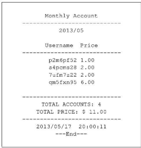
text_image
Monthly Account 2013/05 Username Price p2m6pf52 1.00 s4pcms28 2.00 7ufm7z22 2.00 qm5fxn95 6.00 TOTAL ACCOUNTS: 4 TOTAL PRICE: $ 11.00 2013/05/17 20:00:11 ---End---27.3.5 Account Report Notes
The daily, monthly or last month account report holds up to 2000 entries. If there are more than 2000 accounts created in the same month or same day, the account report's calculations only include the latest 2000.
For example, if 2030 accounts (each priced at \1) have been created from 2013/05/01 00:00:00 to 2013/05/31 19:59:59, the monthly account report includes the latest 2000 accounts, so the total would be \2,000 instead of \$2,030.
Use the Monitor > System Status > Dynamic Guest screen to see the accounts generated on another day or month (up to 2000 entries total).
27.3.6 System Status
This report shows the current system information such as the host name and WAN IP address.
Key combination: A B C C A
The following figure shows an example.
Figure 195 System Status Example
| System Status | |
| Item Description | |
| SYST 02:02:35 WAST Link up WLST Activate FWVR 2.50 (AACG.0) BTVR 1.22 WAMA 00-90-0E-00-4A-29 LAMA 00-90-0E-00-4A-30 WAIP 10.21.2.267 LAIP 172.16.0.1 WLIP 10.59.1.1 DHSP 10.59.1.33 DHEP 10.59.1.254 | |
| CPUS 5% MEMS 40% DKST 5% | |
| 2012/04/12 17:10:22 ---End--- |
The following table describes the labels in this report.
Table 128 System Status
| LABEL DESCRIPTION | |
| SYST This field displays the time since the system was last restarted. | |
| WAST This field displays the WAN connection status. | |
| WLST This field displays the status of the UAG's wireless LAN. | |
| FWVR This field displays the version of the firmware on the UAG. | |
| BTVR This field displays the version of the bootrom. | |
| WAMA This field displays the MAC address of the UAG on the WAN. | |
| LAMA This field displays the MAC address of the UAG on the LAN. | |
| WAIP This field displays the IP address of the WAN port on the UAG. | |
| LAIP This field displays the IP address of the LAN port on the UAG. | |
| WLIP This field displays the IP address of the wireless LAN interface on the UAG. | |
| DHSP This field displays the first of the continuous addresses in the IP address pool. | |
| DHEP This field displays the end of the continuous addresses in the IP address pool. | |
| CPUS This field displays the UAG's recent CPU usage. | |
| MEMS This field displays the UAG's recent memory usage. | |
| DKST | This field displays what percentage of the UAG's onboard flash memory is currently being used. |
28.1 Overview
With Free Time, the UAG can create dynamic guest accounts that allow users to browse the Internet free of charge for a specified period of time.
28.1.1 What You Can Do in this Chapter
Use the Free Time screen (see Section 28.2 on page 282) to turn on this feature to allow users to get a free account for Internet surfing during the specified time period.
28.2 The Free Time Screen
Use this screen to enable and configure the free time settings. Click Configuration > Free Time to open the following screen.
Figure 196 Configuration > Free Time

text_image
Free Time General Settings Enable Free Time Free Time Period: 30 (30-120minutes) Reset Time: 00:00 Maximum Registration Number Before Reset Time: 1 (1-5) Delivery Method: On-Screen Note: If you want to configure ssid profile settings of the account, please go to Billing. Apply ResetThe following table describes the labels in this screen.
Table 129 Configuration > Free Time
| LABEL DESCRIPTION | |
| Enable Free Time | Select the check box to turn on the free time feature.Note: After you set up web authentication policies and enable the free time feature on the UAG, a link displays in the login screen when users try to access the Internet. The link redirects users to a screen where they can get a free account. |
| Free Time Period | Select the duration of time period for which the free time account is allowed to access the Internet. |
| Reset Time | Select the time in 24-hour format at which the new free time account is allowed to access the Internet. |
| Maximum Registration Number Before Reset Time | Enter the maximum number of the users that are allowed to log in for Internet access with a free guest account before the time specified in the Reset Time field.For example, if you set the Maximum Registration Number Before Reset Time to 1 and the Reset Time to 13:00, even the first free guest account has expired at 11:30, the second account still cannot access the Internet until 13:00. |
| Delivery Method | Specify how the UAG provides dynamic guest account information.Select On-Screen to display the user account information in the web screen.Select SMS to use Short Message Service (SMS) to send account information in a text message to the user's mobile device.Select On-Screen and SMS to provide the account information both in the web screen and via SMS text messages.Note: You should have enabled SMS in the Configuration > SMS screen to send text messages to the user's mobile device. |
| Apply Click this button to save your changes to the UAG. | |
| Reset Click this button to return the screen to its last-saved settings. | |
The following figure shows an example login screen with a link to create a free guest account.
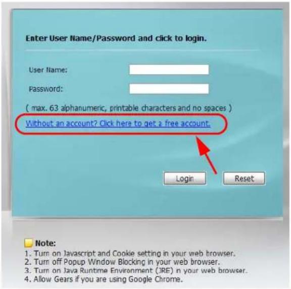
text_image
Enter User Name/Password and click to login. User Name: Password: ( max. 63 alphanumeric, printable characters and no spaces ) Without an account? Click here to get a free account. Login Reset Note: 1. Turn on Javascript and Cookie setting in your web browser. 2. Turn off Popup Window Blocking in your web browser. 3. Turn on Java Runtime Environment (JRE) in your web browser. 4. Allow Gears if you are using Google Chrome.If you enable both online payment service and free time feature on the UAG, the link description in the login screen will be mainly for online payment service. You can still click the link to get a free account.
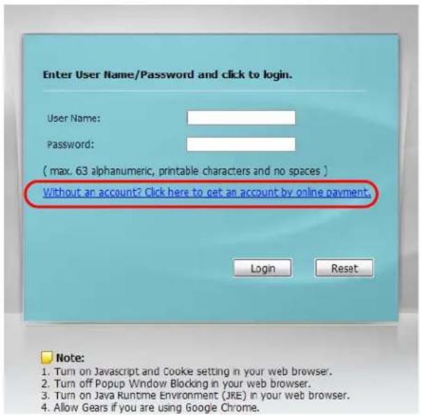
text_image
Enter User Name/Password and click to login. User Name: Password: ( max. 63 alphanumeric, printable characters and no spaces ) Without an account? Click here to get an account by online payment. Login Reset Note: 1. Turn on Javascript and Cooke setting in your web browser. 2. Turn off Popup Window Blocking in your web browser. 3. Turn on Java Runtime Environment (JRE) in your web browser. 4. Allow Gears if you are using Google Chrome.If SMS is enabled on the UAG, you have to enter your mobile phone number before clicking OK to get a free guest account.
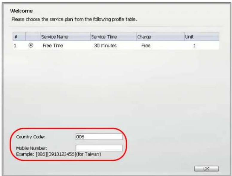
text_image
Welcome Please choose the service plan from the following profile table.Service Name Service Time Charge Unit
1 Free Time 30 minutes Free 1 Country Code: 896 Mobile Number: Example: [886][0910123456](for Taiwan) OKThe guest account information then displays in the screen and/or is sent to the configured mobile phone number.
Welcome
You may now use the internet.
IMPORTANT! MAKE a note for your case-sensitive username and password for logging later. This will be your only opportunity to do so.
This is your account information, please keep this for your internet service.
Your username is uz39mi
Your password is 4v1nbdm
Your time period is 30 minutes
OK
29.1 Overview
The UAG supports Short Message Service (SMS) to send short text messages to mobile phone devices. At the time of writing, the UAG uses ViaNett as the SMS gateway to help forward SMS messages. You must already have a ViaNett account in order to use the SMS service.
29.1.1 What You Can Do in this Chapter
Use the SMS screen (see Section 29.2 on page 286) to turn on the SMS service on the UAG.
29.2 The SMS Screen
Use this screen to enable SMS in order to send dynamic guest account information in text messages. Click Configuration > SMS to open the following screen.
Figure 197 Configuration > SMS

text_image
SMS General Settings Enable SMS Default country code for phone number: 886 (1-4) digit ViaNett Configuration User Name: test@zyxel.com.tw Password: •••••• Retype to Confirm: •••••• Apply ResetThe following table describes the labels in this screen.
Table 130 Configuration > SMS
| LABEL DESCRIPTION | |
| General Settings | |
| Enable SMS Select | the check box to turn on the SMS service. |
| Default country code for phone number | Enter the default country code for the mobile phone number to which you want to send SMS messages. |
| ViaNett Configuration | |
| User Name Enter | the user name for your ViaNett account. |
| Password Type the | Password associated with the user name. |
| Retype to Confirm | Type your password again for confirmation. |
| Apply Click this button | to save your changes to the UAG. |
| Reset Click this button | to return the screen to its last-saved settings. |
30.1 Virtual Private Networks (VPN) Overview
A virtual private network (VPN) provides secure communications between sites without the expense of leased site-to-site lines. A secure VPN is a combination of tunneling, encryption, authentication, access control and auditing. It is used to transport traffic over the Internet or any insecure network that uses TCP/IP for communication.
IPSec VPN
Internet Protocol Security (IPSec) VPN connects IPSec routers or remote users using IPSec client software. This standards-based VPN offers flexible solutions for secure data communications across a public network. IPSec is built around a number of standardized cryptographic techniques to provide confidentiality, data integrity and authentication at the IP layer. The UAG can also combine multiple IPSec VPN connections into one secure network. Here local UAG X uses an IPSec VPN tunnel to remote (peer) UAG Y to connect the local (A) and remote (B) networks.
Figure 198 IPSec VPN Example

flowchart
graph LR
    subgraph A
        A1["Computer"] --> X
        A2["Computer"] --> X
        A3["Computer"] --> X
        A4["Computer"] --> X
        A5["Computer"] --> X
    end
    subgraph X
        X -->|INTERNET VPN Tunnel| Y
        Y -->|Internet VPN Tunnel| X
    end
    subgraph B
        B1["Computer"] -->|INTERNET VPN Tunnel| Y
        B2["Computer"] -->|INTERNET VPN Tunnel| Y
        B3["Computer"] -->|INTERNET VPN Tunnel| Y
    end
30.1.1 What You Can Do in this Chapter
- Use the VPN Connection screens (see Section 30.2 on page 290) to specify which IPSec VPN gateway an IPSec VPN connection policy uses, which devices behind the IPSec routers can use the VPN tunnel, and the IPSec SA settings (phase 2 settings). You can also activate or deactivate and connect or disconnect each VPN connection (each IPSec SA).
- Use the VPN Gateway screens (see Section 30.3 on page 297) to manage the UAG's VPN gateways. A VPN gateway specifies the IPSec routers at either end of a VPN tunnel and the IKE SA settings (phase 1 settings). You can also activate and deactivate each VPN gateway.
30.1.2 What You Need to Know
An IPSec VPN tunnel is usually established in two phases. Each phase establishes a security association (SA), a contract indicating what security parameters the UAG and the remote IPSec router will use. The first phase establishes an Internet Key Exchange (IKE) SA between the UAG and remote IPSec router. The second phase uses the IKE SA to securely establish an IPSec SA through which the UAG and remote IPSec router can send data between computers on the local network and remote network. This is illustrated in the following figure.
Figure 199 VPN: IKE SA and IPSec SA
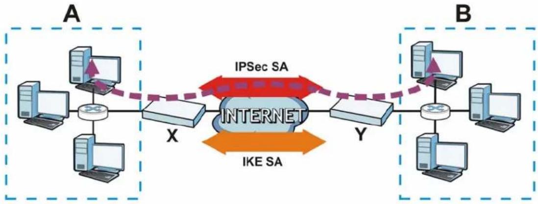
flowchart
graph LR
    subgraph_Host_A["Host A"]
        A1["Computer"] --> X["Switch"]
        A2["Computer"] --> X
        A3["Computer"] --> X
        A4["Computer"] --> X
        A5["Computer"] --> X
    end

    subgraph_Host_B["Host B"]
        B1["Computer"] --> Y["Switch"]
        B2["Computer"] --> Y
        B3["Computer"] --> Y
        B4["Computer"] --> Y
        B5["Computer"] --> Y

    X <-->|IPSec SA| Y
    X <-->|IKE SA| Y
    style X fill:#f9f,stroke:#333
    style Y fill:#bbf,stroke:#333
In this example, a computer in network A is exchanging data with a computer in network B. Inside networks A and B, the data is transmitted the same way data is normally transmitted in the networks. Between routers X and Y, the data is protected by tunneling, encryption, authentication, and other security features of the IPSec SA. The IPSec SA is secure because routers X and Y established the IKE SA first.
Finding Out More
• See Section 30.4 on page 303 for IPSec VPN background information.
• See the help in the IPSec VPN quick setup wizard screens.
30.1.3 Before You Begin
This section briefly explains the relationship between VPN tunnels and other features. It also gives some basic suggestions for troubleshooting.
You should set up the following features before you set up the VPN tunnel.
- In any VPN connection, you have to select address objects to specify the local policy and remote policy. You should set up the address objects first.
- In a VPN gateway, you can select an Ethernet interface, virtual Ethernet interface, VLAN interface, or virtual VLAN interface to specify what address the UAG uses as its IP address when it establishes the IKE SA. You should set up the interface first. See Chapter 10 on page 118.
- In a VPN gateway, you can enable extended authentication. If the UAG is in server mode, you should set up the authentication method (AAA server) first. The authentication method specifies how the UAG authenticates the remote IPSec router. See Chapter 37 on page 368.
- In a VPN gateway, the UAG and remote IPSec router can use certificates to authenticate each other. Make sure the UAG and the remote IPSec router will trust each other's certificates. See Chapter 39 on page 375.
30.2 The VPN Connection Screen
Click Configuration > VPN > IPSec VPN to open the VPN Connection screen. The VPN Connection screen lists the VPN connection policies and their associated VPN gateway(s), and various settings. In addition, it also lets you activate or deactivate and connect or disconnect each VPN connection (each IPSec SA). Click a column's heading cell to sort the table entries by that column's criteria. Click the heading cell again to reverse the sort order.
Figure 200 Configuration > VPN > IPSec VPN > VPN Connection
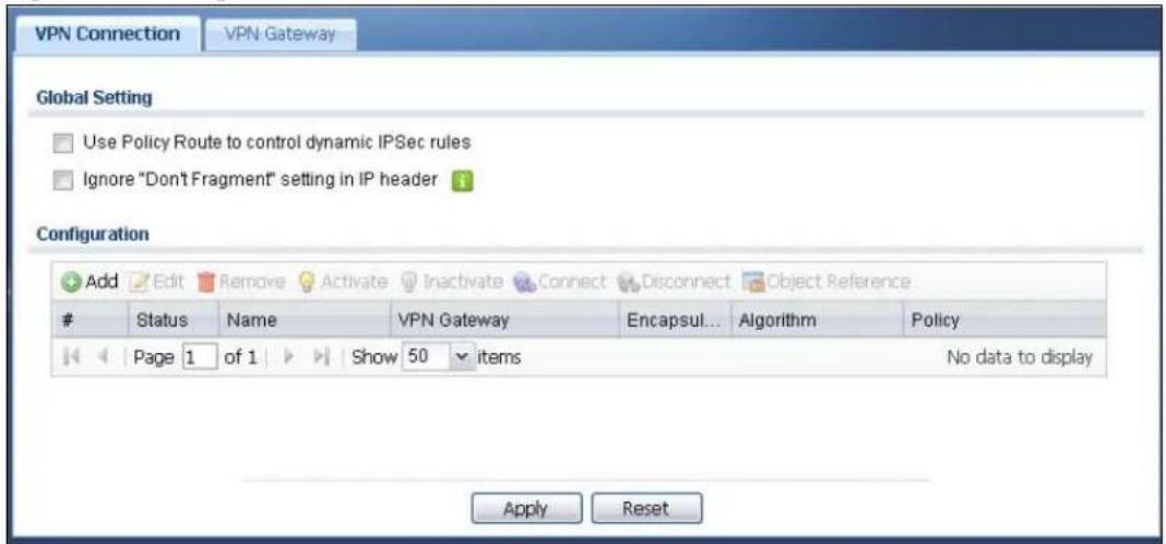
text_image
VPN Connection VPN Gateway Global Setting Use Policy Route to control dynamic IPSec rules Ignore "Don't Fragment" setting in IP header Configuration Add Edit Remove Activate Inactivate Connect Disconnect Object ReferenceStatus Name VPN Gateway Encapsul... Algorithm Policy
Page 1 of 1 Show 50 items No data to display Apply ResetEach field is discussed in the following table. See Section 30.2.1 on page 291 for more information.
Table 131 Configuration > VPN > IPSec VPN > VPN Connection
| LABEL DESCRIPTION | |
| Use Policy Route to control dynamic IPSec rules | Select this to be able to use policy routes to manually specify the destination addresses of dynamic IPSec rules. You must manually create these policy routes. The UAG automatically obtains source and destination addresses for dynamic IPSec rules that do not match any of the policy routes.Clear this to have the UAG automatically obtain source and destination addresses for all dynamic IPSec rules. |
| Ignore "Don't Fragment" setting in IP header | Select this to fragment packets larger than the MTU (Maximum Transmission Unit) that have the “don’t” fragment” bit in the IP header turned on. When you clear this the UAG drops packets larger than the MTU that have the “don’t” fragment” bit in the header turned on. |
| Add Click this to | create a new entry. |
| Edit | Double-click an entry or select it and click Edit to open a screen where you can modify the entry’s settings. |
| Remove | To remove an entry, select it and click Remove. The UAG confirms you want to remove it before doing so. |
| Activate | To turn on an entry, select it and click Activate. |
| Inactivate | To turn off an entry, select it and click Inactivate. |
| Connect | To connect an IPSec SA, select it and click Connect. |
| Disconnect | To disconnect an IPSec SA, select it and click Disconnect. |
| Object Reference | Select an entry and click Object Reference to open a screen that shows which settings use the entry. See Section 10.3.2 on page 129 for an example. |
| # This field is a sequential value, and it is not associated with a specific connection. | |
| Status The activate | ( light bulb) icon is lit when the entry is active and dimmed when the entry is inactive.The connect icon is lit when the interface is connected and dimmed when it is disconnected. |
| Name This field displays the name of the IPSec SA. | |
| VPN Gateway This field displays the associated VPN gateway(s). | |
| Encapsulation This field displays what encapsulation the IPSec SA uses. | |
| Algorithm This field displays what encryption and authentication methods, respectively, the IPSec SA uses. | |
| Policy This field displays the local policy and the remote policy, respectively. | |
| Apply Click Apply to save your changes back to the UAG. | |
| Reset | Click Reset to return the screen to its last-saved settings. |
30.2.1 The VPN Connection Add/Edit Screen
The Add/ Edit VPN Connection screen allows you to create a new VPN connection policy or edit an existing one. To access this screen, go to the Configuration > VPN > IPSec VPN > VPN Connection screen (see Section 30.2 on page 290), and either click the Add icon or select an entry and click the Edit icon.
Figure 201 Configuration > VPN > IPSec VPN > VPN Connection > Add/Edit
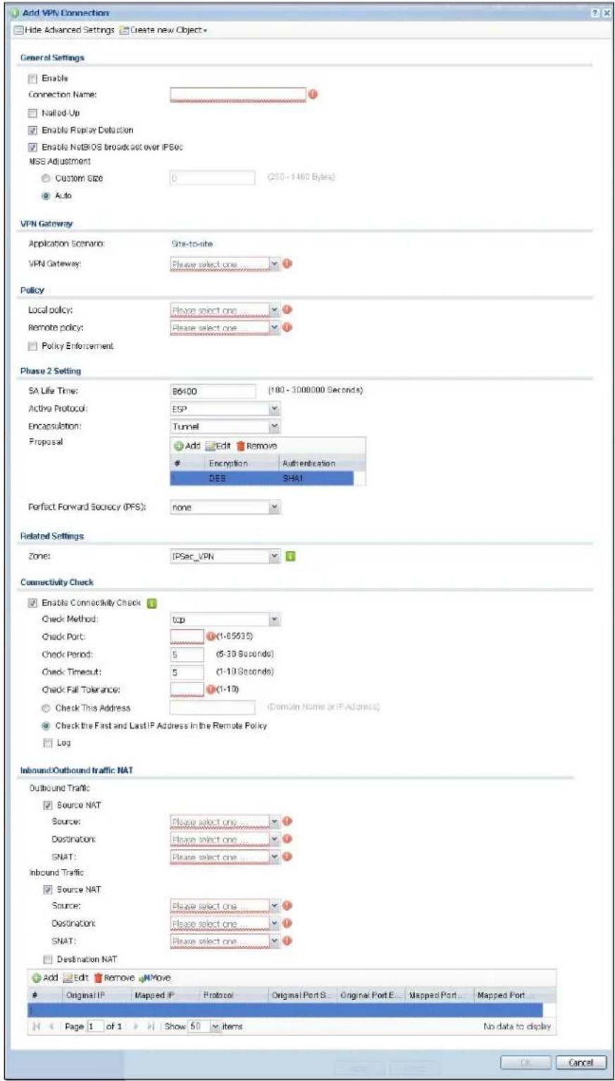
text_image
Add VPN Connection Hide Advanced Settings Create new Object General Settings Enable Connection Name: Nalled Up Enable Replay Detection Enable NoBIOS broadcast over IPSec MSS Adjustment Custom Size 0 (200 - 1460 Bytes) Auto VPN Gateway Application Scenario: Site-to-site VPN Gateway: Please select one ..... Policy Local policy: Please select one ..... Remote policy: Please select one ..... Policy Enforcement Phase 2 Setting SA Life Time: B6400 (180 - 3000000 Seconds) Active Protocol: ESP Encapsulation: Tunnel Proposal Add Edit Remove Encryption Authentication DES SHAT Perfect Forward Secrocy (PFS): none Related Settings Zone: IPSec_VPN Connectivity Check Enable Connectivity Check Check Method: top Check Port: (1-65535) Check Period: 5 (5-30 Seconds) Check Timeout: 5 (1-10 Seconds) Check Fall Tolerance: (1-10) Check This Address (Domain Name or IP Address) Check the First and LastIP Address in the Remote Policy Log Inbound/Outbound traffic NAT Outbound Traffic Source NAT Source: Please select one ..... Destination: Please select one ..... SNAT: Please select one ..... Inbound Traffic Source NAT Source: Please select one ..... Destination: Please select one ..... SNAT: Please select one ..... Destination NAT Add Edit Remove NOWive Original IP Mapped IP Protocol Original Port S Original Port E Mapped Port Mapped Port Page 1 of 1 Show 50 items No data to display OK CancelEach field is described in the following table.
Table 132 Configuration > VPN > IPSec VPN > VPN Connection > Add/Edit
| LABEL DESCRIPTION | |
| Show Advanced Settings / Hide Advanced Settings | Click this button to display a greater or lesser number of configuration fields. |
| Create new Object | Use to configure any new settings objects that you need to use in this screen. |
| General Settings | |
| Enable Select this check | box to activate this VPN connection. |
| Connection Name Type | the name used to identify this IPSec SA. You may use 1-31 alphanumeric characters, underscores( ), or dashes (-), but the first character cannot be a number. This value is case-sensitive. |
| Nailed-Up Select this | if you want the UAG to automatically renegotiate the IPSec SA when the SA life time expires. |
| Enable Replay Detection | Select this check box to detect and reject old or duplicate packets to protect against Denial-of-Service attacks. |
| Enable NetBIOS Broadcast over IPSec | Select this check box if you the UAG to send NetBIOS (Network Basic Input/Output System) packets through the IPSec SA.NetBIOS packets are TCP or UDP packets that enable a computer to connect to and communicate with a LAN. It may sometimes be necessary to allow NetBIOS packets to pass through IPSec SAs in order to allow local computers to find computers on the remote network and vice versa. |
| MSS Adjustment | Select Custom Size to set a specific number of bytes for the Maximum Segment Size (MSS) meaning the largest amount of data in a single TCP segment or IP datagram for this VPN connection.Select Auto to have the UAG automatically set the MSS for this VPN connection. |
| VPN Gateway | |
| Application Scenario | This field is read-only and shows the scenario that the UAG supports.Site-to-site - The remote IPSec router needs to have a static IP address or a domain name. This UAG can initiate the VPN tunnel. |
| VPN Gateway | Select the VPN gateway this VPN connection is to use or select Create new Object to add another VPN gateway for this VPN connection to use. |
| Policy | |
| Local Policy | Select the address corresponding to the local network. Use Create new Object if you need to configure a new one. |
| Remote Policy | Select the address corresponding to the remote network. Use Create new Object if you need to configure a new one. |
| Policy Enforcement | Clear this to allow traffic with source and destination IP addresses that do not match the local and remote policy to use the VPN tunnel. Leave this cleared for free access between the local and remote networks.Selecting this restricts who can use the VPN tunnel. The UAG drops traffic with source and destination IP addresses that do not match the local and remote policy. |
| Phase 2 Settings | |
| SA Life Time | Type the maximum number of seconds the IPSec SA can last. Shorter life times provide better security. The UAG automatically negotiates a new IPSec SA before the current one expires, if there are users who are accessing remote resources. |
| Active Protocol Select | which protocol you want to use in the IPSec SA. Choices are:AH (RFC 2402) - provides integrity, authentication, sequence integrity (replay resistance), and non-repudiation but not encryption. If you select AH, you must select an Authentication algorithm.ESP (RFC 2406) - provides encryption and the same services offered by AH, but its authentication is weaker. If you select ESP, you must select an Encryption algorithm and Authentication algorithm.Both AH and ESP increase processing requirements and latency (delay).The UAG and remote IPSec router must use the same active protocol. |
| Encapsulation Select | which type of encapsulation the IPSec SA uses. Choices areTunnel - this mode encrypts the IP header information and the data.Transport - this mode only encrypts the data.The UAG and remote IPSec router must use the same encapsulation. |
| Proposal Use this section | to manage the encryption algorithm and authentication algorithm pairs the UAG accepts from the remote IPSec router for negotiating the IPSec SA. |
| Add Click this to create a new entry. | |
| Edit Select an entry | and click this to be able to modify it. |
| Remove Select an entry | and click this to delete it. |
| # | This field is a sequential value, and it is not associated with a specific proposal. The sequence of proposals should not affect performance significantly. |
| Encryption | This field is applicable when the Active Protocol is ESP. Select which key size and encryption algorithm to use in the IPSec SA. Choices are:NULL - no encryption key or algorithmDES - a 56-bit key with the DES encryption algorithm3DES - a 168-bit key with the DES encryption algorithmAES128 - a 128-bit key with the AES encryption algorithmAES192 - a 192-bit key with the AES encryption algorithmAES256 - a 256-bit key with the AES encryption algorithmThe UAG and the remote IPSec router must both have at least one proposal that uses use the same encryption and the same key.Longer keys are more secure, but require more processing power, resulting in increased latency and decreased throughput. |
| Authentication Select | which hash algorithm to use to authenticate packet data in the IPSec SA.Choices are SHA1, SHA256, SHA512 and MD5. SHA is generally considered stronger than MD5, but it is also slower.The UAG and the remote IPSec router must both have a proposal that uses the same authentication algorithm. |
| Perfect Forward Secrecy (PFS) | Select whether or not you want to enable Perfect Forward Secrecy (PFS) and, if you do, which Diffie-Hellman key group to use for encryption. Choices are:none - disable PFSDH1 - enable PFS and use a 768-bit random numberDH2 - enable PFS and use a 1024-bit random numberDH5 - enable PFS and use a 1536-bit random numberPFS changes the root key that is used to generate encryption keys for each IPSec SA. The longer the key, the more secure the encryption, but also the longer it takes to encrypt and decrypt information. Both routers must use the same DH key group. |
| Related Settings | |
| Zone Select the security | zone into which to add this VPN connection policy. Any security rules or settings configured for the selected zone apply to this VPN connection policy. |
| Connectivity Check The | UAG can regularly check the VPN connection to the gateway you specified to make sure it is still available. |
| Enable Connectivity Check | Select this to turn on the VPN connection check. |
| Check Method | Select how the UAG checks the connection. The peer must be configured to respond to the method you select.Select icmp to have the UAG regularly ping the address you specify to make sure traffic can still go through the connection. You may need to configure the peer to respond to pings.Select tcp to have the UAG regularly perform a TCP handshake with the address you specify to make sure traffic can still go through the connection. You may need to configure the peer to accept the TCP connection. |
| Check Port | This field displays when you set the Check Method to tcp. Specify the port number to use for a TCP connectivity check. |
| Check Period Enter the number of seconds between connection check attempts. | |
| Check Timeout | Enter the number of seconds to wait for a response before the attempt is a failure. |
| Check Fail Tolerance | Enter the number of consecutive failures allowed before the UAG disconnects the VPN tunnel. The UAG resumes using the first peer gateway address when the VPN connection passes the connectivity check. |
| Check this Address | Select this to specify a domain name or IP address for the connectivity check. Enter that domain name or IP address in the field next to it. |
| Check the First and Last IP Address in the Remote Policy | Select this to have the UAG check the connection to the first and last IP addresses in the connection's remote policy. Make sure one of these is the peer gateway's LAN IP address. |
| Log Select this to have the UAG generate a log every time it checks this VPN connection. | |
| Inbound/Outbound traffic NAT | |
| Outbound Traffic | |
| Source NAT This translation hides the source address of computers in the local network. It may also be necessary if you want the UAG to route packets from computers outside the local network through the IPSec SA. | |
| Source Select the address object that represents the original source address (or select Create new Object to configure a new one). This is the address object for the computer or network outside the local network. The size of the original source address range (Source) must be equal to the size of the translated source address range (SNAT). | |
| Destination Select the address object that represents the original destination address (or select Create new Object to configure a new one). This is the address object for the remote network. | |
| SNAT Select the address object that represents the translated source address (or select Create new Object to configure a new one). This is the address object for the local network. The size of the original source address range (Source) must be equal to the size of the translated source address range (SNAT). | |
| Inbound Traffic | |
| Source NAT This translation hides the source address of computers in the remote network. | |
| Source Select the address object that represents the original source address (or select Create new Object to configure a new one). This is the address object for the remote network. The size of the original source address range (Source) must be equal to the size of the translated source address range (SNAT). | |
| Destination Select the address object that represents the original destination address (or select Create new Object to configure a new one). This is the address object for the local network. | |
| SNAT Select the address object that represents the translated source address (or select Create new Object to configure a new one). This is the address that hides the original source address. The size of the original source address range (Source) must be equal to the size of the translated source address range (SNAT). | |
| Destination NAT | This translation forwards packets (for example, mail) from the remote network to a specific computer (for example, the mail server) in the local network. |
| Add | Click this to create a new entry. Select an entry and click Add to create a new entry after the selected entry. |
| Edit Select an entry and click this to be able to modify it. | |
| Remove Select an entry and click this to delete it. | |
| Move | To change an entry's position in the numbered list, select it and click Move to display a field to type a number for where you want to put that entry and press [ENTER] to move the entry to the number that you typed. |
| # This field is a sequential value, and it is not associated with a specific NAT record. However, the order of records is the sequence in which conditions are checked and executed. | |
| Original IP | Select the address object that represents the original destination address. This is the address object for the remote network. |
| Mapped IP | Select the address object that represents the desired destination address. For example, this is the address object for the mail server. |
| Protocol | Select the protocol required to use this translation. Choices are: TCP, UDP, or All. |
| Original Port Start / Original Port End | These fields are available if the protocol is TCP or UDP. Enter the original destination port or range of original destination ports. The size of the original port range must be the same size as the size of the mapped port range. |
| Mapped Port Start / Mapped Port End | These fields are available if the protocol is TCP or UDP. Enter the translated destination port or range of translated destination ports. The size of the original port range must be the same size as the size of the mapped port range. |
| OK Click OK | to save the changes. |
| Cancel | Click Cancel to discard all changes and return to the main VPN screen. |
30.3 The VPN Gateway Screen
The VPN Gateway summary screen displays the IPSec VPN gateway policies in the UAG, as well as the UAG's address, remote IPSec router's address, and associated VPN connections for each one. In addition, it also lets you activate and deactivate each VPN gateway. To access this screen, click Configuration >VPN > IPSec VPN >VPN Gateway. The following screen appears.
Figure 202 Configuration > VPN > IPSec VPN > VPN Gateway

text_image
VPN Connection VPN Gateway Configuration Add Edit Remove Activate Inactivate Object ReferenceSta... Name My Address Secure Gateway VPN Connection
1 VPN_GW1 ≈wan1 peer.dns.com, 0.0.... Page 1 of 1 Show 50 items Displaying 1 - 1 of 1 Apply ResetEach field is discussed in the following table. See Section 30.3.1 on page 297 for more information.
Table 133 Configuration > VPN > IPSec VPN > VPN Gateway
| LABEL DESCRIPTION | |
| Add Click this to create a new entry. | |
| Edit | Double-click an entry or select it and click Edit to open a screen where you can modify the entry's settings. |
| Remove | To remove an entry, select it and click Remove. The UAG confirms you want to remove it before doing so. |
| Activate | To turn on an entry, select it and click Activate. |
| Inactivate | To turn off an entry, select it and click Inactivate. |
| Object Reference | Select an entry and click Object Reference to open a screen that shows which settings use the entry. See Section 10.3.2 on page 129 for an example. |
| # This field is a sequential value, and it is not associated with a specific VPN gateway. | |
| Status | The activate (light bulb) icon is lit when the entry is active and dimmed when the entry is inactive. |
| Name This field displays the name of the VPN gateway | |
| My address This field displays the interface or a domain name the UAG uses for the VPN gateway. | |
| Secure Gateway This field displays the IP address(es) of the remote IPSec routers. | |
| VPN Connection This field displays VPN connections that use this VPN gateway. | |
| Apply Click Apply to save your changes back to the UAG. | |
| Reset | Click Reset to return the screen to its last-saved settings. |
30.3.1 The VPN Gateway Add/Edit Screen
The VPN Gateway Add/ Edit screen allows you to create a new VPN gateway policy or edit an existing one. To access this screen, go to the VPN Gateway summary screen (see Section 30.3 on page 297), and either click the Add icon or select an entry and click the Edit icon.
Figure 203 Configuration > VPN > IPSec VPN > VPN Gateway > Add/Edit
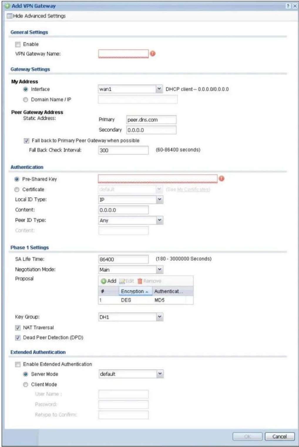
text_image
Add VPN Gateway Hide Advanced Settings General Settings Enable VPN Gateway Name: Gateway Settings My Address Interface wan1 DHCP client -- 0.0.0.0/0.0.0.0 Domain Name / IP Peer Gateway Address Static Address: Primary peer.dns.com Secondary 0.0.0.0 Fall back to Primary Peer Gateway when possible Fall Back Check Interval: 300 (60-86400 seconds) Authentication Pre-Shared Key Certificate default (See My Certificates) Local ID Type: IP Content: 0.0.0.0 Peer ID Type: Any Content: Phase 1 Settings SA Life Time: 86400 (180 - 3000000 Seconds) Negotiation Mode: Main Proposal Add Edit RemoveEncryption Authenticat...
1 DES MD5 Key Group: DH1 NAT Traversal Dead Peer Detection (DPD) Extended Authentication Enable Extended Authentication Server Mode default Client Mode User Name : Password: Retype to Confirm: OK CancelEach field is described in the following table.
Table 134 Configuration > VPN > IPSec VPN > VPN Gateway > Add/Edit
| LABEL DESCRIPTION | |
| Show Advanced Settings / Hide Advanced Settings | Click this button to display a greater or lesser number of configuration fields. |
| General Settings | |
| Enable Select this | check box to activate this VPN gateway policy. |
| VPN Gateway Name | Type the name used to identify this VPN gateway. You may use 1-31 alphanumeric characters, underscores( ), or dashes (-), but the first character cannot be a number. This value is case-sensitive. |
| Gateway Settings | |
| My Address Select | how the IP address of the UAG in the IKE SA is defined.If you select Interface, select the Ethernet interface, VLAN interface, virtual Ethernet interface, virtual VLAN interface or PPPoE/PPTP interface. The IP address of the UAG in the IKE SA is the IP address of the interface.If you select Domain Name / IP, enter the domain name or the IP address of the UAG. The IP address of the UAG in the IKE SA is the specified IP address or the IP address corresponding to the domain name. 0.0.0.0 is not generally recommended as it has the UAG accept IPSec requests destined for any interface address on the UAG. |
| Peer Gateway Address | Select how the IP address of the remote IPSec router in the IKE SA is defined.Select Static Address to enter the domain name or the IP address of the remote IPSec router. You can provide a second IP address or domain name for the UAG to try if it cannot establish an IKE SA with the first one.Fall back to Primary Peer Gateway when possible: When you select this, if the connection to the primary address goes down and the UAG changes to using the secondary connection, the UAG will reconnect to the primary address when it becomes available again and stop using the secondary connection. Users will lose their VPN connection briefly while the UAG changes back to the primary connection. To use this, the peer device at the secondary address cannot be set to use a nailed-up VPN connection. In the Fallback Check Interval field, set how often to check if the primary address is available. |
| Authentication | Note: The UAG and remote IPSec router must use the same authentication method to establish the IKE SA. |
| Pre-Shared Key | Select this to have the UAG and remote IPSec router use a pre-shared key (password) to identify each other when they negotiate the IKE SA. Type the pre-shared key in the field to the right. The pre-shared key can be:· alphanumeric characters or ,;.|`~!@#$%^&*()_+\{}':./<>=-"· pairs of hexadecimal (0-9, A-F) characters, preceded by "0x".Type "0x" at the beginning of a hexadecimal key. For example, "0x0123456789ABCDEF" is in hexadecimal format; "0123456789ABCDEF" is in ASCII format. If you use hexadecimal, you must enter twice as many characters since you need to enter pairs.The UAG and remote IPSec router must use the same pre-shared key. |
| Certificate | Select this to have the UAG and remote IPSec router use certificates to authenticate each other when they negotiate the IKE SA. Then select the certificate the UAG uses to identify itself to the remote IPSec router.This certificate is one of the certificates in My Certificates. If this certificate is self-signed, import it into the remote IPsec router. If this certificate is signed by a CA, the remote IPsec router must trust that CA.Note: The IPSec routers must trust each other's certificates.The UAG uses one of its Trusted Certificates to authenticate the remote IPSec router's certificate. The trusted certificate can be a self-signed certificate or that of a trusted CA that signed the remote IPSec router's certificate. |
| Local ID Type | This field is read-only if the UAG and remote IPSec router use certificates to identify each other. Select which type of identification is used to identify the UAG during authentication. Choices are:IP - the UAG is identified by an IP addressDNS - the UAG is identified by a domain nameE-mail - the UAG is identified by the string specified in this field |
| Content | This field is read-only if the UAG and remote IPSec router use certificates to identify each other. Type the identity of the UAG during authentication. The identity depends on the Local ID Type.IP - type an IP address; if you type 0.0.0.0, the UAG uses the IP address specified in the My Address field. This is not recommended in the following situations:There is a NAT router between the UAG and remote IPSec router.You want the remote IPSec router to be able to distinguish between IPSec SA requests that come from IPSec routers with dynamic WAN IP addresses.In these situations, use a different IP address, or use a different Local ID Type.DNS - type the domain name; you can use up to 63 ASCII characters including spaces, although trailing spaces are truncated. This value is only used for identification and can be any string.E-mail - the UAG is identified by the string you specify here; you can use up to 63 ASCII characters including spaces, although trailing spaces are truncated. This value is only used for identification and can be any string. |
| Peer ID Type | Select which type of identification is used to identify the remote IPSec router during authentication. Choices are:IP - the remote IPSec router is identified by an IP addressDNS - the remote IPSec router is identified by a domain nameE-mail - the remote IPSec router is identified by the string specified in this fieldAny - the UAG does not check the identity of the remote IPSec routerIf the UAG and remote IPSec router use certificates, there is one more choice.Subject Name - the remote IPSec router is identified by the subject name in the certificate |
| LABEL DESCRIPTION | |
| Content | This field is disabled if the Peer ID Type is Any. Type the identity of the remote IPSec router during authentication. The identity depends on the Peer ID Type.If the UAG and remote IPSec router do not use certificates,IP - type an IP address; see the note at the end of this description.DNS - type the domain name; you can use up to 31 ASCII characters including spaces, although trailing spaces are truncated. This value is only used for identification and can be any string.E-mail - the remote IPSec router is identified by the string you specify here; you can use up to 31 ASCII characters including spaces, although trailing spaces are truncated. This value is only used for identification and can be any string.If the UAG and remote IPSec router use certificates, type the following fields from the certificate used by the remote IPSec router.IP - subject alternative name field; see the note at the end of this description.DNS - subject alternative name fieldE-mail - subject alternative name fieldSubject Name - subject name (maximum 255 ASCII characters, including spaces)Note: If Peer ID Type is IP, please read the rest of this section.If you type 0.0.0.0, the UAG uses the IP address specified in the Secure Gateway Address field. This is not recommended in the following situations:There is a NAT router between the UAG and remote IPSec router.You want the remote IPSec router to be able to distinguish between IPSec SA requests that come from IPSec routers with dynamic WAN IP addresses.In these situations, use a different IP address, or use a different Peer ID Type. |
| Phase 1 Settings | |
| SA Life Time (Seconds) | Type the maximum number of seconds the IKE SA can last. When this time has passed, the UAG and remote IPSec router have to update the encryption and authentication keys and re-negotiate the IKE SA. This does not affect any existing IPSec SAs, however. |
| Negotiation Mode | Select the negotiation mode to use to negotiate the IKE SA. Choices areMain - this encrypts the UAG's and remote IPSec router's identities but takes more time to establish the IKE SAAggressive - this is faster but does not encrypt the identitiesThe UAG and the remote IPSec router must use the same negotiation mode. |
| Proposal Use this | section to manage the encryption algorithm and authentication algorithm pairs the UAG accepts from the remote IPSec router for negotiating the IKE SA. |
| Add Click this to create a new entry. | |
| Edit Select an entry and click this to be able to modify it. | |
| Remove Select an entry and click this to delete it. | |
| # | This field is a sequential value, and it is not associated with a specific proposal. The sequence of proposals should not affect performance significantly. |
| LABEL DESCRIPTION | |
| Encryption Select | which key size and encryption algorithm to use in the IKE SA. Choices are:DES - a 56-bit key with the DES encryption algorithm3DES - a 168-bit key with the DES encryption algorithmAES128 - a 128-bit key with the AES encryption algorithmAES192 - a 192-bit key with the AES encryption algorithmAES256 - a 256-bit key with the AES encryption algorithmThe UAG and the remote IPSec router must use the same key size and encryption algorithm. Longer keys require more processing power, resulting in increased latency and decreased throughput. |
| Authentication Select | which hash algorithm to use to authenticate packet data in the IPSec SA.Choices are SHA1, SHA256, SHA512 and MD5. SHA is generally considered stronger than MD5, but it is also slower.The remote IPSec router must use the same authentication algorithm. |
| Key Group | Select which Diffie-Hellman key group (DHx) you want to use for encryption keys.Choices are:DH1 - use a 768-bit random numberDH2 - use a 1024-bit random numberDH5 - use a 1536-bit random numberThe longer the key, the more secure the encryption, but also the longer it takes to encrypt and decrypt information. Both routers must use the same DH key group. |
| NAT Traversal Select | this if any of these conditions are satisfied.This IKE SA might be used to negotiate IPSec SAs that use ESP as the active protocol.There are one or more NAT routers between the UAG and remote IPSec router, and these routers do not support IPSec pass-thru or a similar feature.The remote IPSec router must also enable NAT traversal, and the NAT routers have to forward packets with UDP port 500 and UDP 4500 headers unchanged. |
| Dead Peer Detection (DPD) | Select this check box if you want the UAG to make sure the remote IPSec router is there before it transmits data through the IKE SA. The remote IPSec router must support DPD. If there has been no traffic for at least 15 seconds, the UAG sends a message to the remote IPSec router. If the remote IPSec router responds, the UAG transmits the data. If the remote IPSec router does not respond, the UAG shuts down the IKE SA.If the remote IPSec router does not support DPD, see if you can use the VPN connection connectivity check (see Section 30.2.1 on page 291). |
| Extended Authentication | When multiple IPSec routers use the same VPN tunnel to connect to a single VPN tunnel (telecommuters sharing a tunnel for example), use extended authentication to enforce a user name and password check. This way even though they all know the VPN tunnel's security settings, each still has to provide a unique user name and password. |
| Enable Extended Authentication | Select this if one of the routers (the UAG or the remote IPSec router) verifies a user name and password from the other router using the local user database and/or an external server. |
| Server Mode | Select this if the UAG authenticates the user name and password from the remote IPSec router. You also have to select the authentication method, which specifies how the UAG authenticates this information. |
| Client Mode | Select this radio button if the UAG provides a username and password to the remote IPSec router for authentication. You also have to provide the User Name and the Password. |
| User Name | This field is required if the UAG is inClient Modefor extended authentication. Type the user name the UAG sends to the remote IPSec router. The user name can be 1-31 ASCII characters. It is case-sensitive, but spaces are not allowed. |
| Password | This field is required if the UAG is inClient Modefor extended authentication. Type the password the UAG sends to the remote IPSec router. The password can be 1-31 ASCII characters. It is case-sensitive, but spaces are not allowed. |
| Retype to Confirm Type the password again here to confirm it. | |
| OK | Click OKto save your settings and exit this screen. |
| Cancel | Click Cancelto exit this screen without saving. |
30.4 IPSec VPN Background Information
Here is some more detailed IPSec VPN background information.
IKE SA Overview
The IKE SA provides a secure connection between the UAG and remote IPSec router.
It takes several steps to establish an IKE SA. The negotiation mode determines how many. There are two negotiation modes--main mode and aggressive mode. Main mode provides better security, while aggressive mode is faster.
Note: Both routers must use the same negotiation mode.
These modes are discussed in more detail in Negotiation Mode on page 306. Main mode is used in various examples in the rest of this section.
IP Addresses of the UAG and Remote IPSec Router
To set up an IKE SA, you have to specify the IP addresses of the UAG and remote IPSec router. You can usually enter a static IP address or a domain name for either or both IP addresses. Sometimes, your UAG might offer another alternative, such as using the IP address of a port or interface, as well.
You can also specify the IP address of the remote IPSec router as 0.0.0.0. This means that the remote IPSec router can have any IP address. In this case, only the remote IPSec router can initiate an IKE SA because the UAG does not know the IP address of the remote IPSec router. This is often used for telecommuters.
IKE SA Proposal
The IKE SA proposal is used to identify the encryption algorithm, authentication algorithm, and Diffie-Hellman (DH) key group that the UAG and remote IPSec router use in the IKE SA. In main mode, this is done in steps 1 and 2, as illustrated next.
Figure 204 IKE SA: Main Negotiation Mode, Steps 1 - 2: IKE SA Proposal
One or more proposals, each one consisting of:
encryption algorithm
- authentication algorithm
- Diffie-Hellman key group
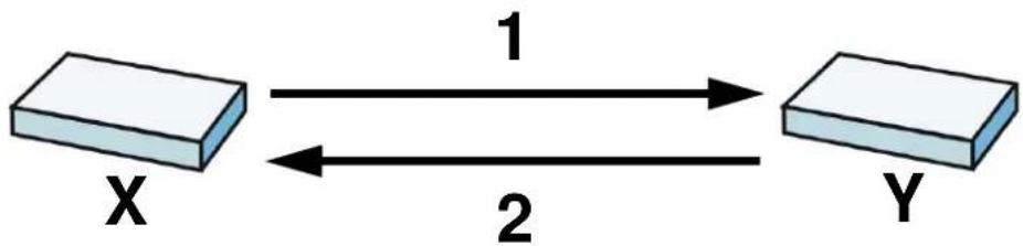
flowchart
graph LR
    X["Block X"] -->|1| Y["Block Y"]
    Y -->|2| X
The UAG sends one or more proposals to the remote IPSec router. (In some devices, you can only set up one proposal.) Each proposal consists of an encryption algorithm, authentication algorithm, and DH key group that the UAG wants to use in the IKE SA. The remote IPSec router selects an acceptable proposal and sends the accepted proposal back to the UAG. If the remote IPSec router rejects all of the proposals, the UAG and remote IPSec router cannot establish an IKE SA.
Note: Both routers must use the same encryption algorithm, authentication algorithm, and DH key group.
In most UAGs, you can select one of the following encryption algorithms for each proposal. The algorithms are listed in order from weakest to strongest.
- Data Encryption Standard (DES) is a widely used method of data encryption. It applies a 56-bit key to each 64-bit block of data.
- Triple DES (3DES) is a variant of DES. It iterates three times with three separate keys, effectively tripling the strength of DES.
- Advanced Encryption Standard (AES) is a newer method of data encryption that also uses a secret key. AES applies a 128-bit key to 128-bit blocks of data. It is faster than 3DES.
Some UAGs also offer stronger forms of AES that apply 192-bit or 256-bit keys to 128-bit blocks of data.
In most UAGs, you can select one of the following authentication algorithms for each proposal. The algorithms are listed in order from weakest to strongest.
- MD5 (Message Digest 5) produces a 128-bit digest to authenticate packet data.
- SHA1 (Secure Hash Algorithm) produces a 160-bit digest to authenticate packet data.
- SHA256 (Secure Hash Algorithm) produces a 256-bit digest to authenticate packet data.
- SHA512 (Secure Hash Algorithm) produces a 512-bit digest to authenticate packet data.
See Diffie-Hellman (DH) Key Exchange on page 304 for more information about DH key groups.
Diffie-Hellman (DH) Key Exchange
The UAG and the remote IPSec router use DH public-key cryptography to establish a shared secret. The shared secret is then used to generate encryption keys for the IKE SA and IPSec SA. In main mode, this is done in steps 3 and 4, as illustrated next.
Figure 205 IKE SA: Main Negotiation Mode, Steps 3 - 4: DH Key Exchange
Diffie-Hellman key exchange
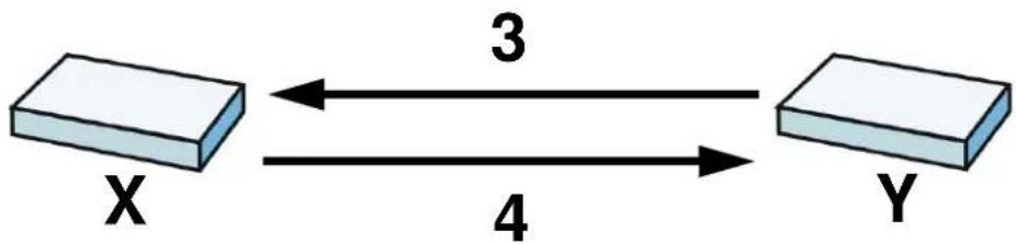
flowchart
graph LR
    X["Block X"] <-->|3| Y["Block Y"]
    Y -->|4| X
DH public-key cryptography is based on DH key groups. Each key group is a fixed number of bits long. The longer the key, the more secure the encryption, but also the longer it takes to encrypt and decrypt information. For example, DH2 keys (1024 bits) are more secure than DH1 keys (768 bits), but DH2 keys take longer to encrypt and decrypt.
Authentication
Before the UAG and remote IPSec router establish an IKE SA, they have to verify each other's identity. This process is based on pre-shared keys and router identities.
In main mode, the UAG and remote IPSec router authenticate each other in steps 5 and 6, as illustrated below. The identities are also encrypted using the encryption algorithm and encryption key the UAG and remote IPSec router selected in previous steps.
Figure 206 IKE SA: Main Negotiation Mode, Steps 5 - 6: Authentication (continued)

flowchart
graph LR
    X["Block X"] -->|Step 5: pre-shared key\nUAG identity, consisting of - ID type - content\nStep 6: pre-shared key\nRemote IPSec router identity, consisting of - ID type - content| Y["Block Y"]
    X <--> Y
    X <--> Y
    style X fill:#f9f,stroke:#333
    style Y fill:#bbf,stroke:#333
You have to create (and distribute) a pre-shared key. The UAG and remote IPSec router use it in the authentication process, though it is not actually transmitted or exchanged.
Note: The UAG and the remote IPSec router must use the same pre-shared key.
Router identity consists of ID type and content. The ID type can be domain name, IP address, or e-mail address, and the content is a (properly-formatted) domain name, IP address, or e-mail address. The content is only used for identification. Any domain name or e-mail address that you
enter does not have to actually exist. Similarly, any domain name or IP address that you enter does not have to correspond to the UAG's or remote IPSec router's properties.
The UAG and the remote IPSec router have their own identities, so both of them must store two sets of information, one for themselves and one for the other router. Local ID type and content refers to the ID type and content that applies to the router itself, and peer ID type and content refers to the ID type and content that applies to the other router.
Note: The UAG's local and peer ID type and content must match the remote IPSec router's peer and local ID type and content, respectively.
For example, in Table 135 on page 306, the UAG and the remote IPSec router authenticate each other successfully. In contrast, in Table 136 on page 306, the UAG and the remote IPSec router cannot authenticate each other and, therefore, cannot establish an IKE SA.
Table 135 VPN Example: Matching ID Type and Content
| UAG REMOTE IPSEC ROUTER | |
| Local ID type: E-mail Local ID type: IP | |
| Local ID content: tom@yourcompany.com Local ID content: 1.1.1.2 | |
| Peer ID type: IP Peer ID type: E-mail | |
| Peer ID content: 1.1.1.2 Peer ID content: tom@yourcompany.com | |
Table 136 VPN Example: Mismatching ID Type and Content
| UAG REMOTE IPSEC ROUTER | |
| Local ID type: E-mail Local ID type: IP | |
| Local ID content: tom@yourcompany.com Local ID content: 1.1.1.2 | |
| Peer ID type: IP Peer ID type: E-mail | |
| Peer ID content: 1.1.1.20 Peer ID content: tom@yourcompany.com | |
It is also possible to configure the UAG to ignore the identity of the remote IPSec router. In this case, you usually set the peer ID type to Any. This is less secure, so you should only use this if your UAG provides another way to check the identity of the remote IPSec router (for example, extended authentication) or if you are troubleshooting a VPN tunnel.
Additional Topics for IKE SA
This section provides more information about IKE SA.
Negotiation Mode
There are two negotiation modes--main mode and aggressive mode. Main mode provides better security, while aggressive mode is faster.
Main mode takes six steps to establish an IKE SA.
Steps 1 - 2: The UAG sends its proposals to the remote IPSec router. The remote IPSec router selects an acceptable proposal and sends it back to the UAG.
Steps 3 - 4: The UAG and the remote IPSec router exchange pre-shared keys for authentication and participate in a Diffie-Hellman key exchange, based on the accepted DH key group, to establish a shared secret.
Steps 5 - 6: Finally, the UAG and the remote IPSec router generate an encryption key (from the shared secret), encrypt their identities, and exchange their encrypted identity information for authentication.
In contrast, aggressive mode only takes three steps to establish an IKE SA. Aggressive mode does not provide as much security because the identity of the UAG and the identity of the remote IPSec router are not encrypted. It is usually used in remote-access situations, where the address of the initiator is not known by the responder and both parties want to use pre-shared keys for authentication. For example, the remote IPSec router may be a telecommuter who does not have a static IP address.
VPN, NAT, and NAT Traversal
In the following example, there is another router (A) between router X and router Y.
Figure 207 VPN/NAT Example
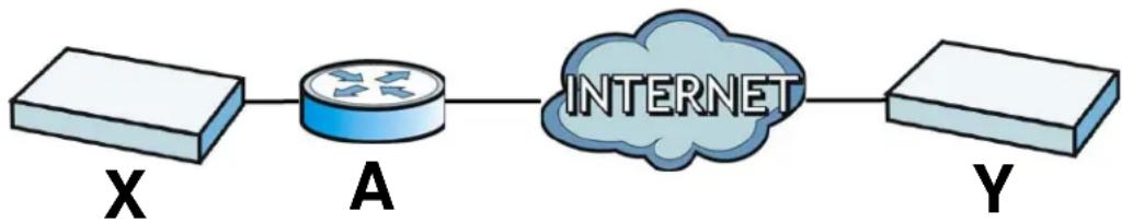
flowchart
graph LR
    A["Router X"] --> B["Router A"]
    B --> C["Internet"]
    C --> D["Router Y"]
If router A does NAT, it might change the IP addresses, port numbers, or both. If router X and router Y try to establish a VPN tunnel, the authentication fails because it depends on this information. The routers cannot establish a VPN tunnel.
Most routers like router A now have an IPSec pass-thru feature. This feature helps router A recognize VPN packets and route them appropriately. If router A has this feature, router X and router Y can establish a VPN tunnel as long as the active protocol is ESP. (See Active Protocol on page 308 for more information about active protocols.)
If router A does not have an IPSec pass-thru or if the active protocol is AH, you can solve this problem by enabling NAT traversal. In NAT traversal, router X and router Y add an extra header to the IKE SA and IPSec SA packets. If you configure router A to forward these packets unchanged, router X and router Y can establish a VPN tunnel.
You have to do the following things to set up NAT traversal.
- Enable NAT traversal on the UAG and remote IPSec router.
- Configure the NAT router to forward packets with the extra header unchanged. (See the field description for detailed information about the extra header.)
The extra header may be UDP port 500 or UDP port 4500, depending on the standard(s) the UAG and remote IPSec router support.
Extended Authentication
Extended authentication is often used when multiple IPSec routers use the same VPN tunnel to connect to a single IPSec router. For example, this might be used with telecommuters.
In extended authentication, one of the routers (the UAG or the remote IPSec router) provides a user name and password to the other router, which uses a local user database and/or an external server to verify the user name and password. If the user name or password is wrong, the routers do not establish an IKE SA.
You can set up the UAG to provide a user name and password to the remote IPSec router, or you can set up the UAG to check a user name and password that is provided by the remote IPSec router.
If you use extended authentication, it takes four more steps to establish an IKE SA. These steps occur at the end, regardless of the negotiation mode (steps 7-10 in main mode, steps 4-7 in aggressive mode).
Certificates
It is possible for the UAG and remote IPSec router to authenticate each other with certificates. In this case, you do not have to set up the pre-shared key, local identity, or remote identity because the certificates provide this information instead.
- Instead of using the pre-shared key, the UAG and remote IPSec router check the signatures on each other's certificates. Unlike pre-shared keys, the signatures do not have to match.
- The local and peer ID type and content come from the certificates.
Note: You must set up the certificates for the UAG and remote IPSec router first.
IPSec SA Overview
Once the UAG and remote IPSec router have established the IKE SA, they can securely negotiate an IPSec SA through which to send data between computers on the networks.
Note: The IPSec SA stays connected even if the underlying IKE SA is not available anymore.
This section introduces the key components of an IPSec SA.
Local Network and Remote Network
In an IPSec SA, the local network, the one(s) connected to the UAG, may be called the local policy. Similarly, the remote network, the one(s) connected to the remote IPSec router, may be called the remote policy.
Active Protocol
The active protocol controls the format of each packet. It also specifies how much of each packet is protected by the encryption and authentication algorithms. IPSec VPN includes two active protocols, AH (Authentication Header, RFC 2402) and ESP (Encapsulating Security Payload, RFC 2406).
Note: The UAG and remote IPSec router must use the same active protocol.
Usually, you should select ESP. AH does not support encryption, and ESP is more suitable with NAT.
Encapsulation
There are two ways to encapsulate packets. Usually, you should use tunnel mode because it is more secure. Transport mode is only used when the IPSec SA is used for communication between the UAG and remote IPSec router (for example, for remote management), not between computers on the local and remote networks.
Note: The UAG and remote IPSec router must use the same encapsulation.
These modes are illustrated below.
Figure 208 VPN: Transport and Tunnel Mode Encapsulation
| Original Packet IP Header TCP | Header | Data | ||
| Transport Mode Packet IP Header AH/ESP | Header | TCP Header | Data | |
| Tunnel Mode Packet IP Header AH/ESP | Header | IP Header TCP Header | Data | |
In tunnel mode, the UAG uses the active protocol to encapsulate the entire IP packet. As a result, there are two IP headers:
- Outside header: The outside IP header contains the IP address of the UAG or remote IPSec router, whichever is the destination.
- Inside header: The inside IP header contains the IP address of the computer behind the UAG or remote IPSec router. The header for the active protocol (AH or ESP) appears between the IP headers.
In transport mode, the encapsulation depends on the active protocol. With AH, the UAG includes part of the original IP header when it encapsulates the packet. With ESP, however, the UAG does not include the IP header when it encapsulates the packet, so it is not possible to verify the integrity of the source IP address.
IPSec SA Proposal and Perfect Forward Secrecy
An IPSec SA proposal is similar to an IKE SA proposal (see IKE SA Proposal on page 303), except that you also have the choice whether or not the UAG and remote IPSec router perform a new DH key exchange every time an IPSec SA is established. This is called Perfect Forward Secrecy (PFS).
If you enable PFS, the UAG and remote IPSec router perform a DH key exchange every time an IPSec SA is established, changing the root key from which encryption keys are generated. As a result, if one encryption key is compromised, other encryption keys remain secure.
If you do not enable PFS, the UAG and remote IPSec router use the same root key that was generated when the IKE SA was established to generate encryption keys.
The DH key exchange is time-consuming and may be unnecessary for data that does not require such security.
Additional Topics for IPSec SA
This section provides more information about IPSec SA in your UAG.
NAT for Inbound and Outbound Traffic
The UAG can translate the following types of network addresses in IPSec SA.
- Source address in outbound packets - this translation is necessary if you want the UAG to route packets from computers outside the local network through the IPSec SA.
- Source address in inbound packets - this translation hides the source address of computers in the remote network.
- Destination address in inbound packets - this translation is used if you want to forward packets (for example, mail) from the remote network to a specific computer (like the mail server) in the local network.
Each kind of translation is explained below. The following example is used to help explain each one.
Figure 209 VPN Example: NAT for Inbound and Outbound Traffic

Source Address in Outbound Packets (Outbound Traffic, Source NAT)
This translation lets the UAG route packets from computers that are not part of the specified local network (local policy) through the IPSec SA. For example, in Figure 209 on page 310, you have to configure this kind of translation if you want computer M to establish a connection with any computer in the remote network (B). If you do not configure it, the remote IPSec router may not route messages for computer M through the IPSec SA because computer M's IP address is not part of its local policy.
To set up this NAT, you have to specify the following information:
- Source - the original source address; most likely, computer M's network.
- Destination - the original destination address; the remote network (B).
• SNAT - the translated source address; the local network (A).
Source Address in Inbound Packets (Inbound Traffic, Source NAT)
You can set up this translation if you want to change the source address of computers in the remote network. To set up this NAT, you have to specify the following information:
- Source - the original source address; the remote network (B).
- Destination - the original destination address; the local network (A).
- SNAT - the translated source address; a different IP address (range of addresses) to hide the original source address.
Destination Address in Inbound Packets (Inbound Traffic, Destination NAT)
You can set up this translation if you want the UAG to forward some packets from the remote network to a specific computer in the local network. For example, in Figure 209 on page 310, you can configure this kind of translation if you want to forward mail from the remote network to the mail server in the local network (A).
You have to specify one or more rules when you set up this kind of NAT. The UAG checks these rules similar to the way it checks rules for a firewall. The first part of these rules define the conditions in which the rule apply.
- Original IP - the original destination address; the remote network (B).
- Protocol - the protocol [TCP, UDP, or both] used by the service requesting the connection.
- Original Port - the original destination port or range of destination ports; in Figure 209 on page 310, it might be port 25 for SMTP.
The second part of these rules controls the translation when the condition is satisfied.
- Mapped IP - the translated destination address; in Figure 209 on page 310, the IP address of the mail server in the local network (A).
- Mapped Port - the translated destination port or range of destination ports.
The original port range and the mapped port range must be the same size.
IPSec VPN Example
Here is an example of configuring a site-to-site IPSec VPN.
Figure 210 IPSec VPN Example

flowchart
graph LR
    subgraph LAN
        A["Computer 1"] --> B["Router X"]
        C["Computer 2"] --> B
        D["Computer 3"] --> B
        B --> E["Router X 1.2.3.4"]
        E --> F["VPN Tunnel"]
        F --> G["Router Y 2.2.2.2"]
        G --> H["Router Y"]
        H --> I["Router X 172.16.1.0/24"]
    end
    subgraph LAN
        J["Computer 1"] --> K["Router X"]
        L["Computer 2"] --> K
        M["Computer 3"] --> K
        N["Computer 4"] --> K
        O["Computer 5"] --> K
    end
UAG X uses 1.2.3.4 as its public address, and remote IPSec router Y uses 2.2.2.2. Create the VPN tunnel between the UAG's LAN subnet (192.168.1.0/24) and the LAN subnet behind the peer IPSec router (172.16.1.0/24).
Set Up the VPN Gateway that Manages the IKE SA
In Configuration > VPN > IPSec VPN > VPN Gateway > Add, enable the VPN gateway and name it (VPN_GW_EXAMPLE here). Set My Address to Interface and select a WAN interface. Set Peer Gateway Address to Static Address and enter the remote IPSec router's public IP address (2.2.2.2 here) as the Primary. Set Authentication to Pre-Shared Key and enter 12345678. Click OK.
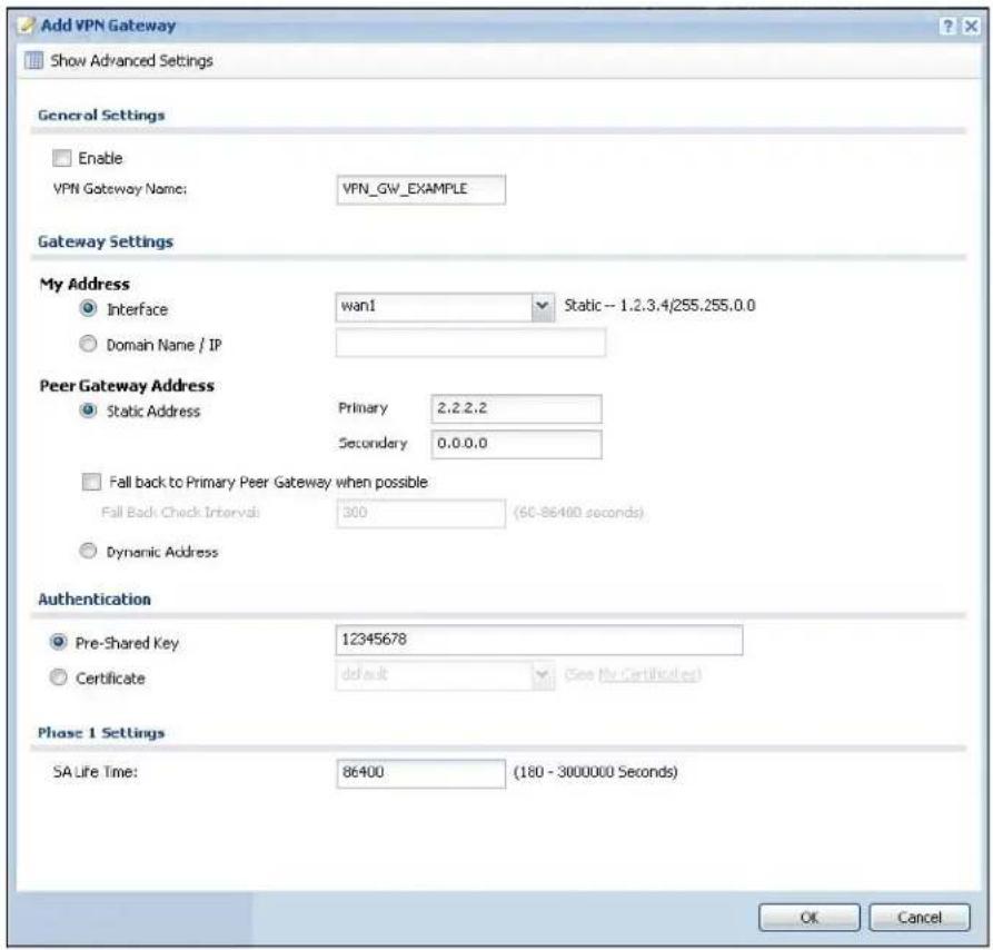
text_image
Add VPN Gateway Show Advanced Settings General Settings Enable VPN Gateway Name: VPN_GW_EXAMPLE Gateway Settings My Address Interface wan1 Static -- 1.2.3.4/255.255.0.0 Domain Name / IP Peer Gateway Address Static Address Primary 2.2.2.2 Secondary 0.0.0.0 Fall back to Primary Peer Gateway when possible Fall Back Check Interval: 300 (60-86400 seconds) Dynamic Address Authentication Pre-Shared Key 12345678 Certificate default (See My Certificates) Phase 1 Settings SA Life Time: 86400 (180 - 3000000 Seconds) OK CancelSet Up the VPN Connection that Manages the IPSec SA
1 In Configuration > VPN > IPSec VPN > VPN Connection > Add, click Create New Object > Address to create an address object for the remote network. Set the Address Type to SUBNET, the Network field to 172.16.1.0, and the Netmask to 255.255.255.0.
2 Enable the VPN connection and name it ("VPN_CONN_EXAMPLE"). Set VPN Gateway to Site-to-site and select the VPN gateway you configured (VPN_GW_EXAMPLE). Set Local Policy to LAN1_SUBNET and Remote Policy to VPN_REMOTE_SUBNET for the remote. Click OK.
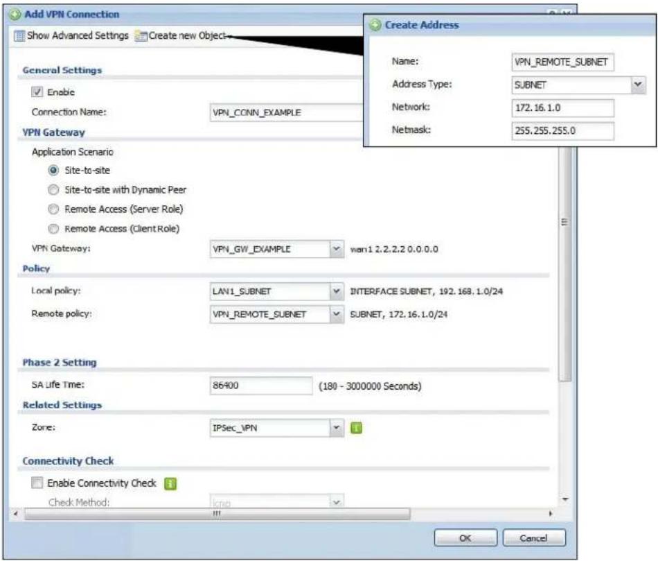
text_image
Add VPN Connection Show Advanced Settings Create new Object General Settings Enable Connection Name: VPN_CONN_EXAMPLE VPN Gateway Application Scenario Site-to-site Site-to-site with Dynamic Peer Remote Access (Server Role) Remote Access (Client Role) VPN Gateway: VPN_GW_EXAMPLE wan1.2.2.2.0.0.0.0 Policy Local policy: LAN1_SUBNET INTERFACE SUBNET, 192.168.1.0/24 Remote policy: VPN_REMOTE_SUBNET SUBNET, 172.16.1.0/24 Phase 2 Setting SA Life Time: 86400 (180 - 3000000 Seconds) Related Settings Zone: IPSec_IPN Connectivity Check Enable Connectivity Check Check Method:Bandwidth Management
31.1 Overview
Bandwidth management provides a convenient way to manage the use of various services on the network. It manages general protocols (for example, HTTP and FTP) and applies traffic prioritization to enhance the performance of delay-sensitive applications like voice and video.
31.1.1 What You Can Do in this Chapter
Use the BWM screens (see Section 31.2 on page 319) to control bandwidth for services passing through the UAG, and it identifies the conditions that refine this.
31.1.2 What You Need to Know
When you allow a service, you can restrict the bandwidth it uses. It controls TCP and UDP traffic. Use policy routes to manage other types of traffic (like ICMP).
Note: Bandwidth management in policy routes has priority over policy routes to manage the bandwidth of TCP and UDP traffic.
If you want to use a service, make sure both the firewall allow the service's packets to go through the UAG.
Note: The UAG checks firewall rules before it checks bandwidth management rules for traffic going through the UAG.
Bandwidth management examines every TCP and UDP connection passing through the UAG. Then, you can specify, by port, whether or not the UAG continues to route the connection.
BWM Type
The UAG supports two types of bandwidth management: Shared and Per-user.
The Shared BWM type is selected by default in a bandwidth management rule. All users to which the rule is applied need to share the bandwidth configured in the rule.
If the BWM type is set to Per-user in a rule, every user that matches the rule can use up to the configured bandwidth by his/her own.
In the following example, you configure a Per-user bandwidth management rule for billing-users to limit outgoing traffic to 300 kbs. Then all billing-users (A, B and C) can send 300 kbps of traffic.
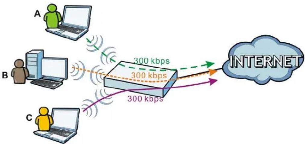
flowchart
graph LR
    A["User A"] -->|300 kbps| Router
    B["User B"] -->|300 kbps| Router
    C["User C"] -->|300 kbps| Router
    Router -->|300 kbps| Internet
DiffServ and DSCP Marking
QoS is used to prioritize source-to-destination traffic flows. All packets in the same flow are given the same priority. CoS (class of service) is a way of managing traffic in a network by grouping similar types of traffic together and treating each type as a class. You can use CoS to give different priorities to different packet types.
DiffServ (Differentiated Services) is a class of service (CoS) model that marks packets so that they receive specific per-hop treatment at DiffServ-compliant network devices along the route based on the application types and traffic flow. Packets are marked with DiffServ Code Points (DSCPs) indicating the level of service desired. This allows the intermediary DiffServ-compliant network devices to handle the packets differently depending on the code points without the need to negotiate paths or remember state information for every flow. In addition, applications do not have to request a particular service or give advanced notice of where the traffic is going.
Connection and Packet Directions
Bandwidth management looks at the connection direction, that is from which interface the connection was initiated and to which interface the connection is going.
A connection has outbound and inbound packet flows. The UAG controls the bandwidth of traffic of each flow as it is going out through an interface.
- The outbound traffic flows from the connection initiator to the connection responder.
- The inbound traffic flows from the connection responder to the connection initiator.
For example, a LAN1 to WAN connection is initiated from LAN1 and goes to the WAN.
- Outbound traffic goes from a LAN1 device to a WAN device. Bandwidth management is applied before sending the packets out a WAN interface on the UAG.
- Inbound traffic comes back from the WAN device to the LAN1 device. Bandwidth management is applied before sending the traffic out a LAN1 interface.
Figure 211 LAN1 to WAN Connection and Packet Directions

flowchart
graph LR
    A["LAN1"] -->|Connection| B["WAN"]
    A --> C["A"]
    C --> D["BWM"]
    D --> E["Inbound"]
    E --> F["INTERNET"]
    style A fill:#f9f,stroke:#333
    style B fill:#ccf,stroke:#333
    style C fill:#cfc,stroke:#333
    style D fill:#fcc,stroke:#333
    style E fill:#cff,stroke:#333
    style F fill:#ffc,stroke:#333
Outbound and Inbound Bandwidth Limits
You can limit an application's outbound or inbound bandwidth. This limit keeps the traffic from using up too much of the out-going interface's bandwidth. This way you can make sure there is bandwidth for other applications. When you apply a bandwidth limit to outbound or inbound traffic, each member of the out-going zone can send up to the limit. Take a LAN1 to WAN policy for example.
- Outbound traffic is limited to 200 kbps. The connection initiator is on the LAN1 so outbound means the traffic traveling from the LAN1 to the WAN. Each of the WAN zone's two interfaces can send the limit of 200 kbps of traffic.
- Inbound traffic is limited to 500 kbs. The connection initiator is on the LAN1 so inbound means the traffic traveling from the WAN to the LAN1.
Figure 212 LAN1 to WAN, Outbound 200 kbps, Inbound 500 kbps
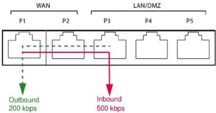
flowchart
graph TD
    A["WAN"] --> B["P1"]
    A --> C["P2"]
    D["LAN/DMZ"] --> E["P3"]
    D --> F["P4"]
    D --> G["P5"]
    H["Outbound 200 kbps"] --> I
    J["Inbound 500 kbps"] --> K
Bandwidth Management Priority
- The UAG gives bandwidth to higher-priority traffic first, until it reaches its configured bandwidth rate.
- Then lower-priority traffic gets bandwidth.
- The UAG uses a fairness-based (round-robin) scheduler to divide bandwidth among traffic flows with the same priority.
- The UAG automatically treats traffic with bandwidth management disabled as priority 7 (the lowest priority).
Maximize Bandwidth Usage
Maximize bandwidth usage allows applications with maximize bandwidth usage enabled to "borrow" any unused bandwidth on the out-going interface.
After each application gets its configured bandwidth rate, the UAG uses the fairness-based scheduler to divide any unused bandwidth on the out-going interface amongst applications that need more bandwidth and have maximize bandwidth usage enabled.
Unused bandwidth is divided equally. Higher priority traffic does not get a larger portion of the unused bandwidth.
Bandwidth Management Behavior
The following sections show how bandwidth management behaves with various settings. For example, you configure LAN1 to WAN policies for FTP servers A and B. Each server tries to send 1000 kbps, but the WAN is set to a maximum outgoing speed of 1000 kbps. You configure policy A for server A's traffic and policy B for server B's traffic.
Figure 213 Bandwidth Management Behavior

flowchart
graph LR
    subgraph LAN1
        A["A"]
        B["B"]
    end
    subgraph WAN
        B2["B"]
        C["C"]
    end
    A -->|1000 kbps| B
    B -->|1000 kbps| C
    C -->|1000 kbps| BWM["BWM"]
    style LAN1 fill:#f9f,stroke:#333
    style WAN fill:#bbf,stroke:#333
Configured Rate Effect
In the following table the configured rates total less than the available bandwidth and maximize bandwidth usage is disabled, both servers get their configured rate.
Table 137 Configured Rate Effect
| POLICY | CONFIGURED RATE | MAX. B. U. | PRIORITY | ACTUAL RATE |
| A 300 | kbps No 1 300 kbps | |||
| B 200 | kbps No 1 200 kbps |
Priority Effect
Here the configured rates total more than the available bandwidth. Because server A has higher priority, it gets up to its configured rate (800 kbps), leaving only 200 kbps for server B.
Table 138 Priority Effect
| POLICY | CONFIGURED RATE | MAX. B. U. | PRIORITY | ACTUAL RATE |
| A 800 | kbps Yes 1 800 kbps | |||
| B | 1000 kbps | Yes | 2 | 200 kbps |
Maximize Bandwidth Usage Effect
With maximize bandwidth usage enabled, after each server gets its configured rate, the rest of the available bandwidth is divided equally between the two. So server A gets its configured rate of 300 kbps and server B gets its configured rate of 200 kbps. Then the UAG divides the remaining bandwidth (1000 - 500 = 500) equally between the two (500 / 2 = 250 kbps for each). The priority has no effect on how much of the unused bandwidth each server gets.
So server A gets its configured rate of 300 kbps plus 250 kbps for a total of 550 kbps. Server B gets its configured rate of 200 kbps plus 250 kbps for a total of 450 kbps.
Table 139 Maximize Bandwidth Usage Effect
| POLICY | CONFIGURED RATE | MAX. B. U. | PRIORITY | ACTUAL RATE |
| A 300 | kbps Yes 1 550 kbps | |||
| B 200 | kbps Yes 2 450 kbps |
Priority and Over Allotment of Bandwidth Effect
Server A has a configured rate that equals the total amount of available bandwidth and a higher priority. You should regard extreme over allotment of traffic with different priorities (as shown here) as a configuration error. Even though the UAG still attempts to let all traffic get through and not be lost, regardless of its priority, server B gets almost no bandwidth with this configuration.
Table 140 Priority and Over Allotment of Bandwidth Effect
| POLICY | CONFIGURED RATE | MAX. B. U. | PRIORITY | ACTUAL RATE | |
| A 1000 | kbps | Yes | 1 | 999 kbps | |
| B 1000 | kbps | Yes | 2 | 1 kbps | |
Finding Out More
• See DSCP Marking and Per-Hop Behavior on page 168 for a description of DSCP marking.
31.2 The Bandwidth Management Screen
The Bandwidth management screens control the bandwidth allocation for TCP and UDP traffic. You can use source interface, destination interface, destination port, schedule, user, source, destination information, DSCP code and service type as criteria to create a sequence of specific conditions, similar to the sequence of rules used by firewalls, to specify how the UAG handles the DSCP value and allocate bandwidth for the matching packets.
Click Configuration > BWM to open the following screen. This screen allows you to enable/disable bandwidth management and add, edit, and remove user-defined bandwidth management policies.
The default bandwidth management policy is the one with the priority of "default". It is the last policy the UAG checks if traffic does not match any other bandwidth management policies you have configured. You cannot remove, activate, deactivate or move the default bandwidth management policy.
Figure 214 Configuration > BWM
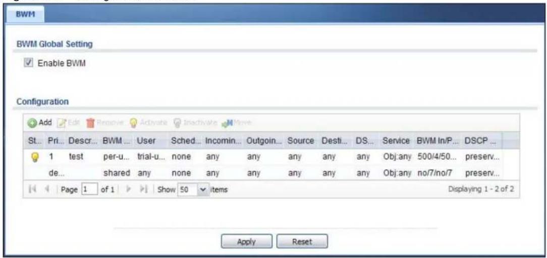
text_image
BWM BWM Global Setting Enable BWM Configuration Add Edit Remove Activate Inactivate Move St... Pri... Descr... BWM ... User Sched... Incomin... Outgoin... Source Desti... DS... Service BWM In/P... DSCP ... 1 test per-u... trial-u... none any any any any any any Obj:any 500/4/50... preserv... de... shared any none any any any any any Obj:any no/7/no/7 preserv... Page 1 of 1 Show 50 items Displaying 1 - 2 of 2 Apply ResetThe following table describes the labels in this screen. See Section 31.2.1 on page 321 for more information as well.
Table 141 Configuration > BWM
| LABEL DESCRIPTION | |
| Enable BWM Select this check box to activate management bandwidth. | |
| Add | Click this to create a new entry. Select an entry and click Add to create a new entry after the selected entry. |
| Edit Select an entry and click this to be able to modify it. | |
| Remove Select an entry and click this to delete it. | |
| Activate | To turn on an entry, select it and click Activate. |
| Inactivate | To turn off an entry, select it and click Inactivate. |
| Move | To change an entry's position in the numbered list, select it and click Move to display a field to type a number for where you want to put that entry and press [ENTER] to move the entry to the number that you typed. |
| Status The activate (light bulb) icon is lit when the entry is active and dimmed when the entry is inactive. The status icon is not available for the default bandwidth management policy. | |
| Priority | This is the position of your bandwidth management policy in the list. The ordering of your rules is important as rules are applied in sequence.This field displays default for the default bandwidth management policy that the UAG performs on traffic that does not match any other bandwidth management policy. |
| Description This is the descriptive name of the policy. | |
| BWM Type | This is the bandwidth management type of the policy. |
| User | This is the user name or user group to which the policy applies. If any displays, the policy applies to all users. |
| Schedule | This is the schedule that defines when the policy applies. none means the policy always applies. |
| Incoming Interface | This is the source interface of the traffic to which this policy applies. |
| Outgoing Interface | This is the destination interface of the traffic to which this policy applies. |
| Source | This is the source address or address group for whom this policy applies. If any displays, the policy is effective for every source. |
| LABEL DESCRIPTION | |
| Destination | This is the destination address or address group for whom this policy applies. If any displays, the policy is effective for every destination. |
| DSCP Code | This is the DSCP value of the incoming or outgoing packets to which this policy applies.any means all DSCP values or no DSCP marker.default means traffic with a DSCP value of 0. This is usually best effort traffic. |
| Service | This is the service object to which this policy applies. If any displays, the policy is effective for every service. |
| BWM In/Pri/Out/Pri | This field shows the amount of bandwidth the traffic can use.In - This is how much inbound bandwidth, in kilobits per second, this policy allows the matching traffic to use. Inbound refers to the traffic the UAG sends to a connection's initiator. If no displays here, this policy does not apply bandwidth management for the inbound traffic.Out - This is how much outgoing bandwidth, in kilobits per second, this policy allows the matching traffic to use. Outbound refers to the traffic the UAG sends out from a connection's initiator. If no displays here, this policy does not apply bandwidth management for the outbound traffic.Pri - This is the priority for the incoming (the first Pri value) or outgoing (the second Pri value) traffic that matches this policy. The smaller the number, the higher the priority. Traffic with a higher priority is given bandwidth before traffic with a lower priority. The UAG ignores this number if the incoming and outgoing limits are both set to 0. In this case the traffic is automatically treated as being set to the lowest priority (7) regardless of this field's configuration. |
| DSCP Marking | This is how the UAG handles the DSCP value of the incoming and outgoing packets that match this policy.preserve means the UAG does not modify the DSCP value of the route's packets.default means the UAG sets the DSCP value of the route's packets to 0.If this field displays a DSCP value, the UAG applies that DSCP value to the route's packets.The "af" choices stand for Assured Forwarding. The number following the "af" identifies one of four classes and one of three drop preferences. See Section 12.4 on page 175 for more details. |
| Apply Click Apply | to save your changes back to the UAG. |
| Reset | Click Reset to return the screen to its last-saved settings. |
31.2.1 The Bandwidth Management Add/Edit Screen
The Configuration > BWM Add/ Edit screen allows you to create a new condition or edit an existing one. To access this screen, go to the Configuration > BWM screen (see Section 31.2 on page 319), and either click the Add icon or select an entry and click the Edit icon.
Figure 215 Configuration > BWM > Edit (For the Default Policy)
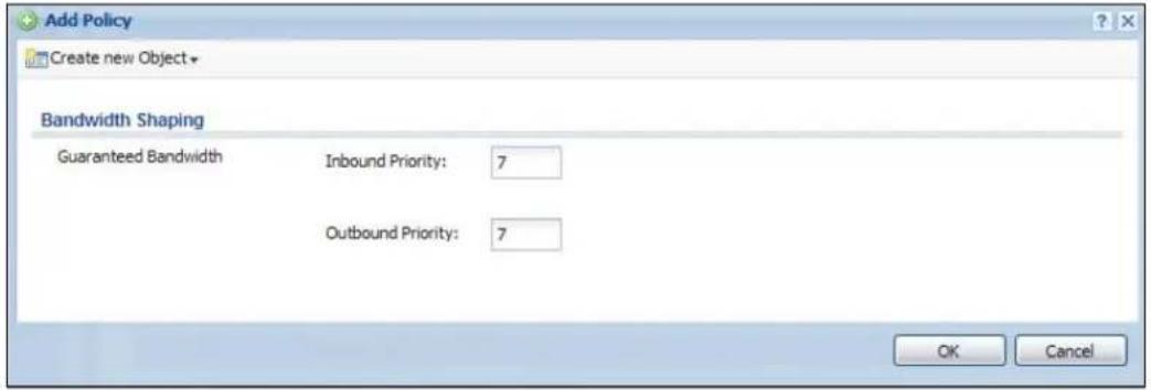
text_image
Add Policy Create new Object Bandwidth Shaping Guaranteed Bandwidth Inbound Priority: 7 Outbound Priority: 7 OK CancelFigure 216 Configuration > BWM > Add/Edit
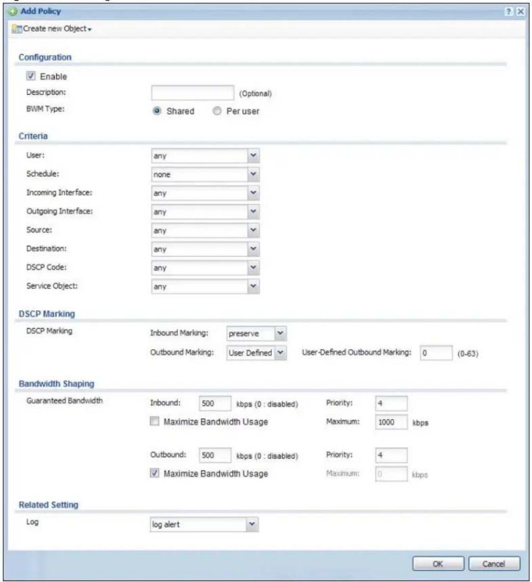
text_image
Add Policy Create new Object Configuration Enable Description: (Optional) BWM Type: Shared Per user Criteria User: any Schedule: none Incoming Interface: any Outgoing Interface: any Source: any Destination: any DSCP Code: any Service Object: any DSCP Marking DSCP Marking Inbound Marking: preserve Outbound Marking: User Defined User-Defined Outbound Marking: 0 (0-63) Bandwidth Shaping Guaranteed Bandwidth Inbound: 500 kbps (0 : disabled) Priority: 4 Maximize Bandwidth Usage Maximum: 1000 kbps Outbound: 500 kbps (0 : disabled) Priority: 4 Maximize Bandwidth Usage Maximum: 0 kbps Related Setting Log log alert OK CancelThe following table describes the labels in this screen.
Table 142 Configuration > Bandwidth Management > Add/Edit
| LABEL DESCRIPTION | |
| Create new Object | Use to configure any new settings objects that you need to use in this screen. |
| Enable Select this | check box to turn on this policy. |
| Description | Enter a description of this policy. You can use alphanumeric and ()+/:=?!*#@$_%-characters, and it can be up to 60 characters long. |
| BWM Type | Select Shared to have users that match this policy to share the bandwidth configured in this policy.Select Per user to allow every user that matches this policy to use up to the bandwidth configured in this policy. |
| User | Select a user name or user group to which to apply the policy. Use Create new Object if you need to configure a new user account. Select any to apply the policy for every user. |
| Schedule | Select a schedule that defines when the policy applies or select Create new Object to configure a new one (see Chapter 36 on page 364 for details). Otherwise, select none to make the policy always effective. |
| Incoming Interface | Select the source interface of the traffic to which this policy applies. |
| Outgoing Interface | Select the destination interface of the traffic to which this policy applies. |
| Source | Select a source address or address group for whom this policy applies. Use Create new Object if you need to configure a new one. Select any if the policy is effective for every source. |
| Destination | Select a destination address or address group for whom this policy applies. Use Create new Object if you need to configure a new one. Select any if the policy is effective for every destination. |
| DSCP Code | Select a DSCP code point value of incoming or outgoing packets to which this policy applies or select User Define to specify another DSCP code point. The lower the number the higher the priority with the exception of 0 which is usually given only best-effort treatment.any means all DSCP value or no DSCP marker.default means traffic with a DSCP value of 0. This is usually best effort traffic.The “af” choices stand for Assured Forwarding. The number following the “af” identifies one of four classes and one of three drop preferences. See Section 12.4 on page 175 for more details. |
| User-Defined DSCP Code | Use this field to specify a custom DSCP code point. |
| Service Object | Select a service or service group to identify the type of traffic to which this policy applies. |
| DSCP Marking | Set how the UAG handles the DSCP value of the incoming and outgoing packets that match this policy. |
| Inbound Marking | Inbound refers to the traffic the UAG sends to a connection’s initiator. Outbound refers to the traffic the UAG sends out from a connection’s initiator.Select one of the pre-defined DSCP values to apply or select User Defined to specify another DSCP value. The “af” choices stand for Assured Forwarding. The number following the “af” identifies one of four classes and one of three drop preferences. See Section 12.4 on page 175 for more details.Select preserve to have the UAG keep the packets’ original DSCP value.Select default to have the UAG set the DSCP value of the packets to 0. |
Table 142 Configuration > Bandwidth Management > Add/Edit
| LABEL DESCRIPTION | |
| Bandwidth Shaping | Configure these fields to set the amount of bandwidth the matching traffic can use. |
| Inbound kbps | Type how much inbound bandwidth, in kilobits per second, this policy allows the traffic to use. Inbound refers to the traffic the UAG sends to a connection's initiator.If you enter 0 here, this policy does not apply bandwidth management for the matching traffic that the UAG sends to the initiator. Traffic with bandwidth management disabled (inbound and outbound are both set to 0) is automatically treated as the lowest priority (7).If the sum of the bandwidths for routes using the same next hop is higher than the actual transmission speed, lower priority traffic may not be sent if higher priority traffic uses all of the actual bandwidth. |
| Outbound kbps | Type how much outbound bandwidth, in kilobits per second, this policy allows the traffic to use. Outbound refers to the traffic the UAG sends out from a connection's initiator.If you enter 0 here, this policy does not apply bandwidth management for the matching traffic that the UAG sends out from the initiator. Traffic with bandwidth management disabled (inbound and outbound are both set to 0) is automatically treated as the lowest priority (7).If the sum of the bandwidths for routes using the same next hop is higher than the actual transmission speed, lower priority traffic may not be sent if higher priority traffic uses all of the actual bandwidth. |
| Priority | Enter a number between 1 and 7 to set the priority for traffic that matches this policy. The smaller the number, the higher the priority.Traffic with a higher priority is given bandwidth before traffic with a lower priority.The UAG uses a fairness-based (round-robin) scheduler to divide bandwidth between traffic flows with the same priority.The number in this field is ignored if the incoming and outgoing limits are both set to 0. In this case the traffic is automatically treated as being set to the lowest priority (7) regardless of this field's configuration. |
| Maximize Bandwidth Usage | This field displays when the inbound or outbound bandwidth management is not set to 0. Enable maximize bandwidth usage to let the traffic matching this policy "borrow" any unused bandwidth on the out-going interface.After each application or type of traffic gets its configured bandwidth rate, the UAG uses the fairness- based scheduler to divide any unused bandwidth on the out-going interface amongst applications and traffic types that need more bandwidth and have maximize bandwidth usage enabled. |
| Related Setting | |
| Log | Select whether to have the UAG generate a log (log), log and alert (log alert) or not (no) for packets that match the policy. |
| OK Click OK to save your changes back to the UAG. | |
| Cancel | Click Cancel to exit this screen without saving your changes. |
32.1 Overview
This chapter describes how to set up user accounts, user groups, and user settings for the UAG. You can also set up rules that control when users have to log in to the UAG before the UAG routes traffic for them.
32.1.1 What You Can Do in this Chapter
- The User screen (see Section 32.2 on page 327) provides a summary of all user accounts.
- The Group screen (see Section 32.3 on page 331) provides a summary of all user groups. In addition, this screen allows you to add, edit, and remove user groups. User groups may consist of access users and other user groups. You cannot put admin users in user groups
- The Setting screen (see Section 32.4 on page 332) controls default settings, login settings, lockout settings, and other user settings for the UAG. You can also use this screen to specify when users must log in to the UAG before it routes traffic for them.
32.1.2 What You Need To Know
User Account
A user account defines the privileges of a user logged into the UAG. User accounts are used in firewall rules, in addition to controlling access to configuration and services in the UAG.
User Types
These are the types of user accounts the UAG uses.
Table 143 Types of User Accounts
| TYPE ABILITIES | LOGIN METHOD(S) | |
| Admin Users | ||
| admin Change UAG configuration (web, CLI) WWW, TELNET, SSH, limited-admin Look at UAG configuration (web, CLI) Perform basic diagnostics (CLI) | FTP, Console | |
| WWW, TELNET, SSH, Console | ||
| Access Users | ||
| ext-user External user account WWW | ||
| ext-group-user External group user account WWW | ||
| guest-manager Create dynamic guest accounts WWW | ||
| pre-subscriber | Access network services | Web Authentication Portal |
| dynamic-guest | Access network services | Web Authentication Portal |
Note: The default admin account is always authenticated locally, regardless of the authentication method setting. (See Chapter 38 on page 372 for more information about authentication methods.)
Ext-User Accounts
Set up an ext-user account if the user is authenticated by an external server and you want to set up specific policies for this user in the UAG. If you do not want to set up policies for this user, you do not have to set up an ext-user account.
All ext-user users should be authenticated by an external server, such as RADIUS. If the UAG tries to use the local database to authenticate an ext-user, the authentication attempt always fails. (This is related to AAA servers and authentication methods, which are discussed in Chapter 37 on page 368 and Chapter 38 on page 372, respectively.)
Note: If the UAG tries to authenticate an ext-user using the local database, the attempt always fails.
Once an ext-user user has been authenticated, the UAG tries to get the user type (see Table 143 on page 325) from the external server. If the external server does not have the information, the UAG sets the user type for this session to User.
For the rest of the user attributes, such as reauthentication time, the UAG checks the following places, in order.
1 User account in the remote server.
2 User account (Ext-User) in the UAG.
3 Default user account for RADIUS users (radius-users) in the UAG.
See Setting up User Attributes in an External Server on page 337 for a list of attributes and how to set up the attributes in an external server.
Ext-Group-User Accounts
Ext-Group-User accounts are similar to ext-user accounts but allow you to group users by the value of the group membership attribute configured for the RADIUS server. See Section 37.2.1 on page 369 for more on the group membership attribute.
Dynamic-Guest Accounts
Dynamic guest accounts are guest accounts, but are created dynamically and stored in the UAG's local user database. A dynamic guest account has a dynamically-created user name and password. A dynamic guest account user can access the UAG's services only within a given period of time and will become invalid after the expiration date/time.
There are three types of dynamic guest accounts depending on how they are created or authenticated: billing-users, ua-users and trial-users.
billing-users are guest account created with the guest manager account or an external printer and paid by cash or created and paid via the on-line payment service. ua-users are users that log in
from the user agreement page. trial-users are free guest accounts that are created with the Free Time function.
Pre-Subscriber Accounts
Use the pre-subscriber account to test the Internet connection between the UAG and the ISP. The UAG does not impose time limitations or charges on this account. Thus, anyone who logs in with this account is able to gain Internet access for free.
User Groups
User groups may consist of user accounts or other user groups. Use user groups when you want to create the same rule for several user accounts, instead of creating separate rules for each one.
Note: You cannot put access users and admin users in the same user group.
Note: You cannot put the default admin account into any user group.
The sequence of members in a user group is not important.
User Awareness
By default, users do not have to log into the UAG to use the network services it provides. The UAG automatically routes packets for everyone. If you want to restrict network services that certain users can use via the UAG, you can require them to log in to the UAG first. The UAG is then 'aware' of the user who is logged in and you can create 'user-aware policies' that define what services they can use. See Section 32.4.2 on page 336 for a user-aware login example.
Finding Out More
- See Section 32.5 on page 337 for some information on users who use an external authentication server in order to log in.
32.2 User Summary Screen
The User screen provides a summary of all user accounts. To access this screen, login to the Web Configurator, and click Configuration > Object > User/ Group > User.
Figure 217 Configuration > Object > User/Group > User
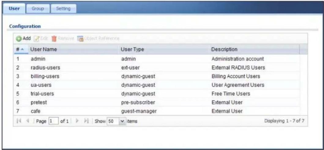
text_image
User Group Setting Configuration Add Edit Remove Object ReferenceUser Name User Type Description
1 admin admin Administration account 2 radius-users ext-user External RADIUS Users 3 billing-users dynamic-guest Billing Account Users 4 ua-users dynamic-guest User Agreement Users 5 trial-users dynamic-guest Free Time Users 6 pretest pre-subscriber External User 7 cafe guest-manager External User Page 1 of 1 Show 50 items Displaying 1 - 7 of 7The following table describes the labels in this screen.
Table 144 Configuration > Object > User/Group > User
| LABEL DESCRIPTION | |
| Add Click this to create a new entry. | |
| Edit | Double-click an entry or select it and click Edit to open a screen where you can modify the entry's settings. |
| Remove | To remove an entry, select it and click Remove. The UAG confirms you want to remove it before doing so. |
| Object Reference | Select an entry and click Object Reference to open a screen that shows which settings use the entry. See Section 10.3.2 on page 129 for an example. |
| # This field is a sequential value, and it is not associated with a specific user. | |
| User Name This field displays the user name of each user. | |
| User Type This field displays the kind of account of each user. These are the kinds of user account the UAG supports.admin - this user can look at and change the configuration of the UAGlimited-admin - this user can look at the configuration of the UAG but not to change itdynamic-guest - this user has access to the UAG's services but cannot look at the configuration.ext-user - this user account is maintained in a remote server, such as RADIUS.ext-group-user - this user account is maintained in a remote server, such as RADIUS.guest-manager - this user can log in via the web configurator login screen and create dynamic guest accounts using the Account Generator screen that pops up. See Section 26.3.1 on page 263 for detailed information about the Account Generator screen.pre-subscriber - this user has access to the UAG's services but cannot look at the configuration. | |
| Description This field displays the description for each user. | |
32.2.1 User Add/Edit Screen
The User Add/ Edit screen allows you to create a new user account or edit an existing one.
32.2.1.1 Rules for User Names
Enter a user name from 1 to 31 characters.
The user name can only contain the following characters:
- Alphanumeric A-z 0-9 (there is no unicode support)
- _ [underscores]
- [ d a s h e s ]
The first character must be alphabetical (A-Z a-z), an underscore (_), or a dash (-). Other limitations on user names are:
- User names are case-sensitive. If you enter a user 'bob' but use 'BOB' when connecting via CIFS or FTP, it will use the account settings used for 'BOB' not 'bob'.
- User names have to be different than user group names.
• Here are the reserved user names:
text_image
• a d m • a d m i n • a n y • b i n • d a e m o n • d e b u g • d e v i c e h a e c i v e d • f t p • g a m e s • l d a p - u s e r s • l p • m a i l • n e w s • n o • o p e r a t o r • r a d i u s - u s e r s • r o o t • s h u t d o w n • s s h d • s y n c • u u c p • z y x e lTo access this screen, go to the User screen (see Section 32.2 on page 327), and either click the Add icon or select an entry and click the Edit icon.
Figure 218 Configuration > Object > User/Group > User > Add/Edit
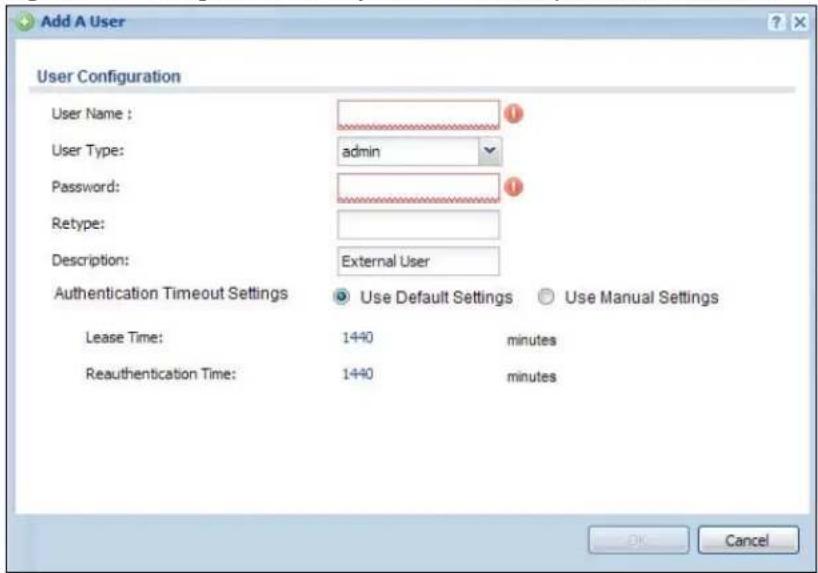
text_image
Add A User User Configuration User Name : user Type: admin Password: Retype: Description: External User Authentication Timeout Settings Use Default Settings Use Manual Settings Lease Time: 1440 minutes Reauthentication Time: 1440 minutes OK CancelThe following table describes the labels in this screen.
Table 145 Configuration > Object > User/Group > User > Add/Edit
| LABEL DESCRIPTION | |
| User Name | Type the user name for this user account. You may use 1-31 alphanumeric characters, underscores( ), or dashes (-), but the first character cannot be a number. This value is case-sensitive. User names have to be different than user group names, and some words are reserved. See Section 32.2.1.1 on page 329. |
| User Type This field | displays the types of user accounts the UAG uses:admin - this user can look at and change the configuration of the UAGlimited-admin - this user can look at the configuration of the UAG but not to change itext-user - this user account is maintained in a remote server, such as RADIUS. See Ext-User Accounts on page 326 for more information about this type.ext-group-user - this user account is maintained in a remote server, such as RADIUS. See Ext-Group-User Accounts on page 326 for more information about this type.guest-manager - this user can log in via the web configurator login screen and create dynamic guest accounts using the Account Generator screen that pops up. See Section 26.3.1 on page 263 for detailed information about the Account Generator screen.pre-subscriber - this user has access to the UAG's services but cannot look at the configuration. |
| Password | This field is not available if you select the ext-user or ext-group-user type.Enter the password of this user account. It can consist of 4 - 31 alphanumeric characters. |
| Retype | This field is not available if you select the ext-user or ext-group-user type. |
| Group Identifier | This field is available for a ext-group-user type user account.Specify the value of the RADIUS server's Group Membership Attribute that identifies the group to which this user belongs. |
| Associated AAA Server Object | This field is available for a ext-group-user type user account. Select the AAA server to use to authenticate this account's users. |
| Description | Enter the description of each user, if any. You can use up to 60 printable ASCII characters. Default descriptions are provided. |
| Authentication Timeout Settings | If you want the system to use default settings, select Use Default Settings. If you want to set authentication timeout to a value other than the default settings, select Use Manual Settings then fill your preferred values in the fields that follow. |
| Lease Time | If you select Use Default Settings in the User Settings field, the default lease time is shown.If you select Use Manual Settings, you need to enter the number of minutes this user has to renew the current session before the user is logged out. You can specify 1 to 1440 minutes. You can enter 0 to make the number of minutes unlimited. Admin users renew the session every time the main screen refreshes in the Web Configurator. Access users can renew the session by clicking the Renew button on their screen. If you allow access users to renew time automatically (see Section 32.4 on page 332), the users can select this check box on their screen as well. In this case, the session is automatically renewed before the lease time expires. |
| Reauthentication Time | If you select Use Default Settings in the User Settings field, the default lease time is shown.If you select Use Manual Settings, you need to type the number of minutes this user can be logged into the UAG in one session before the user has to log in again. You can specify 1 to 1440 minutes. You can enter 0 to make the number of minutes unlimited. Unlike Lease Time, the user has no opportunity to renew the session without logging out. |
| LABEL DESCRIPTION | |
| OK | Click OK to save your changes back to the UAG. |
| Cancel | Click Cancel to exit this screen without saving your changes. |
32.3 User Group Summary Screen
User groups consist of access users and other user groups. You cannot put admin users in user groups. The Group screen provides a summary of all user groups. In addition, this screen allows you to add, edit, and remove user groups. To access this screen, login to the Web Configurator, and click Configuration > Object > User/Group > Group.
Figure 219 Configuration > Object > User/Group > Group
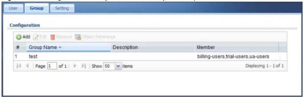
text_image
User Group Setting Configuration Add Edit Remove Object ReferenceGroup Name Description Member
1 test billing-users,trial-users,ua-users Page 1 of 1 Show 50 items Displaying 1 - 1 of 1The following table describes the labels in this screen. See Section 32.3.1 on page 331 for more information as well.
Table 146 Configuration > Object > User/Group > Group
| LABEL DESCRIPTION | |
| Add Click this to create a new entry. | |
| Edit | Double-click an entry or select it and click Edit to open a screen where you can modify the entry's settings. |
| Remove | To remove an entry, select it and click Remove. The UAG confirms you want to remove it before doing so. Removing a group does not remove the user accounts in the group. |
| Object Reference | Select an entry and click Object Reference to open a screen that shows which settings use the entry. See Section 10.3.2 on page 129 for an example. |
| # This field is a sequential value, and it is not associated with a specific user group. | |
| Group Name This field displays the name of each user group. | |
| Description This field displays the description for each user group. | |
| Member | This field lists the members in the user group. Each member is separated by a comma. |
32.3.1 Group Add/Edit Screen
The Group Add/ Edit screen allows you to create a new user group or edit an existing one. To access this screen, go to the Group screen (see Section 32.3 on page 331), and either click the Add icon or select an entry and click the Edit icon.
Figure 220 Configuration > Object > User/Group > Group > Add/Edit
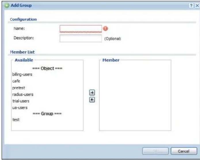
text_image
Add Group Configuration Name: Description: (Optional) Member List Available === Object === billing-users cafe pretest radius-users trial-users ua-users === Group === test Member CancelThe following table describes the labels in this screen.
Table 147 Configuration > Object > User/Group > Group > Add/Edit
| LABEL DESCRIPTION | |
| Name | Type the name for this user group. You may use 1-31 alphanumeric characters, underscores( ), or dashes (-), but the first character cannot be a number. This value is case-sensitive. User group names have to be different than user names. |
| Description | Enter the description of the user group, if any. You can use up to 60 characters, punctuation marks, and spaces. |
| Member List | The Member list displays the names of the users and user groups that have been added to the user group. The order of members is not important. Select users and groups from the Available list that you want to be members of this group and move them to the Member list. You can double-click a single entry to move it or use the [Shift] or [Ctrl] key to select multiple entries and use the arrow button to move them.Move any members you do not want included to the Available list. |
| OK | Click OK to save your changes back to the UAG. |
| Cancel | Click Cancel to exit this screen without saving your changes. |
32.4 The User/Group Setting Screen
The Setting screen controls default settings, login settings, lockout settings, and other user settings for the UAG. You can also use this screen to specify when users must log in to the UAG before it routes traffic for them.
To access this screen, login to the Web Configurator, and click Configuration > Object > User/Group > Setting.
Figure 221 Configuration > Object > User/Group > Setting
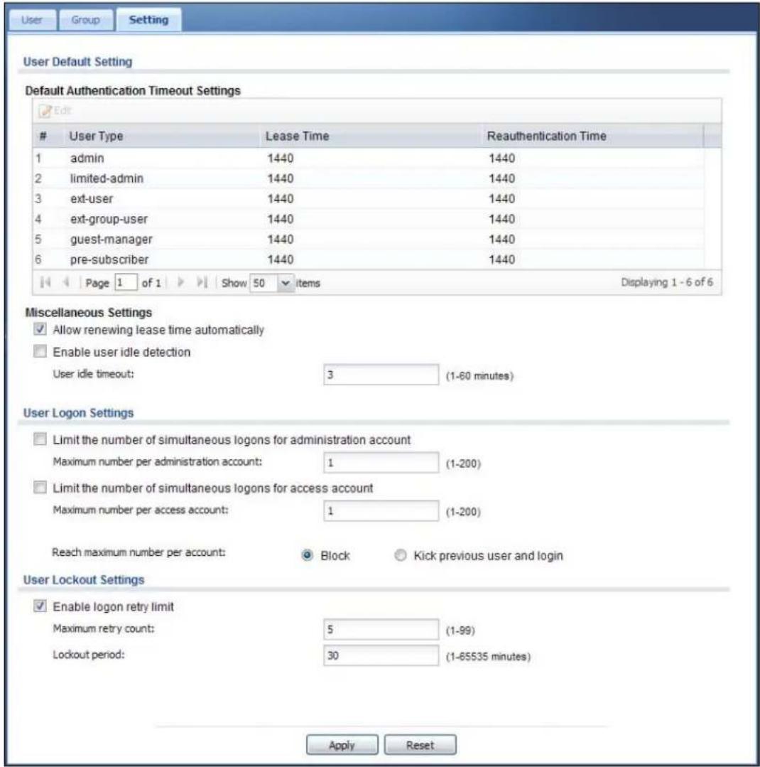
text_image
User Group Setting User Default Setting Default Authentication Timeout Settings EditUser Type Lease Time Reauthentication Time
1 admin 1440 1440 2 limited-admin 1440 1440 3 ext-user 1440 1440 4 ext-group-user 1440 1440 5 guest-manager 1440 1440 6 pre-subscriber 1440 1440 Page 1 of 1 Show 50 items Displaying 1 - 6 of 6 Miscellaneous Settings Allow renewing lease time automatically Enable user idle detection User idle timeout: 3 (1-60 minutes) User Logon Settings Limit the number of simultaneous logons for administration account Maximum number per administration account: 1 (1-200) Limit the number of simultaneous logons for access account Maximum number per access account: 1 (1-200) Reach maximum number per account: Block Kick previous user and login User Lockout Settings Enable logon retry limit Maximum retry count: 5 (1-99) Lockout period: 30 (1-65535 minutes) Apply ResetThe following table describes the labels in this screen.
Table 148 Configuration > Object > User/Group > Setting
| LABEL DESCRIPTION | |
| User Default Setting | |
| Default AuthenticationTimeout Settings | These authentication timeout settings are used by default when you create a new user account. They also control the settings for any existing user accounts that are set to use the default settings. You can still manually configure any user account's authentication timeout settings. |
| Edit | Double-click an entry or select it and click Edit to open a screen where you can modify the entry's settings. |
| # | This field is a sequential value, and it is not associated with a specific entry. |
| User Type These are the kinds of user account the UAG supports.admin - this user can look at and change the configuration of the UAGlimited-admin - this user can look at the configuration of the UAG but not to change itext-user - this user account is maintained in a remote server, such as RADIUS. See Ext-User Accounts on page 326 for more information about this type.ext-group-user - this user account is maintained in a remote server, such as RADIUS. See Ext-Group-User Accounts on page 326 for more information about this type.guest-manager - this user can log in via the web configurator login screen and create dynamic guest accounts using the Account Generator screen that pops up.pre-subscriber - this user has access to the UAG's services but cannot look at the configuration. | |
| Lease Time | This is the default lease time in minutes for each type of user account. It defines the number of minutes the user has to renew the current session before the user is logged out.Admin users renew the session every time the main screen refreshes in the Web Configurator. Access users can renew the session by clicking the Renew button on their screen. If you allow access users to renew time automatically (see Section 32.4 on page 332), the users can select this check box on their screen as well. In this case, the session is automatically renewed before the lease time expires. |
| Reauthentication Time This is the default reauthentication time in minutes for each type of user account. It defines the number of minutes the user can be logged into the UAG in one session before having to log in again. Unlike Lease Time, the user has no opportunity to renew the session without logging out. | |
| Miscellaneous Settings | |
| Allow renewing lease time automatically | Select this check box if access users can renew lease time automatically, as well as manually, simply by selecting the Updating lease time automatically check box on their screen. |
| Enable user idle detection | This is applicable for access users.Select this check box if you want the UAG to monitor how long each access user is logged in and idle (in other words, there is no traffic for this access user). The UAG automatically logs out the access user once the User idle timeout has been reached. |
| User idle timeout This is applicable for access users.This field is effective when Enable user idle detection is checked. Type the number of minutes each access user can be logged in and idle before the UAG automatically logs out the access user. | |
| User Logon Settings | |
| Limit number of simultaneous logons for administration account | Select this check box if you want to set a limit on the number of simultaneous logins by admin users. If you do not select this, admin users can log in as many times as they want at the same time using the same or different IP addresses. |
| Maximum number per administration account | This field is effective when Limit number of simultaneous logons for administration account is checked. Type the maximum number of simultaneous logins by each admin user. |
| Limit number of simultaneous logons for access account | Select this check box if you want to set a limit on the number of simultaneous logins by non-admin users. If you do not select this, access users can log in as many times as they want as long as they use different IP addresses. |
| Maximum number per access account | This field is effective when Limit number of simultaneous logons for access account is checked. Type the maximum number of simultaneous logins by each access user. |
| Reach maximum number per account | SelectBlockto stop new users from logging in when theMaximum number per access accountis reached.SelectKick previous user and loginto disassociate the first user that logged in and allow new user to log in when theMaximum number per access accountis reached. |
| User Lockout Settings | |
| Enable logon retry limit Select this check box to set a limit on the number of times each user can login unsuccessfully (for example, wrong password) before the IP address is locked out for a specified amount of time. | |
| Maximum retry count | This field is effective whenEnable logon retry limitis checked. Type the maximum number of times each user can login unsuccessfully before the IP address is locked out for the specifiedLockout period. The number must be between 1 and 99. |
| Lockout period | This field is effective whenEnable logon retry limitis checked. Type the number of minutes the user must wait to try to login again, if logon retry limit is enabled and theMaximum retry countis reached. This number must be between 1 and 65,535 (about 45.5 days). |
| Apply ClickApplyto save the changes. | |
| Reset | ClickResetto return the screen to its last-saved settings. |
32.4.1 Default User Settings Edit Screen
The Edit User Default Settings screen allows you to set the default authentication timeout settings for the selected type of user account. These default authentication timeout settings also control the settings for any existing user accounts that are set to use the default settings. You can still manually configure any user account's authentication timeout settings.
To access this screen, go to the Configuration > Object > User/ Group > Setting screen (see Section 32.4 on page 332), and select one of the Default Settings section's entry and click the Edit icon.
Figure 222 Configuration > Object > User/Group > Setting > Edit

text_image
Edit User Auth Settings User Type: admin Lease Time: 1440 (0-1440 minutes, 0 is unlimited) Reauthentication Time: 1440 (0-1440 minutes, 0 is unlimited) OK CancelThe following table describes the labels in this screen.
Table 149 Configuration > Object > User/Group > Setting > Edit
| LABEL DESCRIPTION | |
| User Type This read-only field identifies the type of user account for which you are configuring the default settings.admin - this user can look at and change the configuration of the UAGlimited-admin - this user can look at the configuration of the UAG but not to change it.ext-user - this user account is maintained in a remote server, such as RADIUS. See Ext-User Accounts on page 326 for more information about this type.ext-group-user - this user account is maintained in a remote server, such as RADIUS. See Ext-Group-User Accounts on page 326 for more information about this type.guest-manager - this user can log in via the web configurator login screen and create dynamic guest accounts using the Account Generator screen that pops up.pre-subscriber - this user has access to the UAG's services but cannot look at the configuration. | |
| Lease Time Enter the number of minutes this type of user account has to renew the current session before the user is logged out. You can specify 1 to 1440 minutes. You can enter 0 to make the number of minutes unlimited.Admin users renew the session every time the main screen refreshes in the Web Configurator. Access users can renew the session by clicking the Renew button on their screen. If you allow access users to renew time automatically (see Section 32.4 on page 332), the users can select this check box on their screen as well. In this case, the session is automatically renewed before the lease time expires. | |
| Reauthentication Time | Select this option and type the number of minutes this type of user account can be logged into the UAG in one session before the user has to log in again. You can specify 1 to 1440 minutes. You can enter 0 to make the number of minutes unlimited. Unlike Lease Time, the user has no opportunity to renew the session without logging out. |
| OK | Click OK to save your changes back to the UAG. |
| Cancel | Click Cancel to exit this screen without saving your changes. |
32.4.2 User Aware Login Example
Access users cannot use the Web Configurator to browse the configuration of the UAG. Instead, after access users log into the UAG, the following screen appears.
Figure 223 Web Configurator for Non-Admin Users

text_image
test, You now have logged in. Click the logout button to terminate the access session. You could renew your lease time by clicking the Renew button. For security reason you must login in again after 24 hours 0 minutes. User-defined lease time (max 1440 minutes): 1440 Renew □ Updating lease time automatically Remaining time before lease timeout (hh:mm:ss): 23:59:40 Remaining time before auth. timeout (hh:mm): 23:59 LogoutThe following table describes the labels in this screen.
Table 150 Web Configurator for Non-Admin Users
| LABEL DESCRIPTION | |
| User-defined lease time (max ... minutes) | Access users can specify a lease time shorter than or equal to the one that you specified. The default value is the lease time that you specified. |
| Renew Access users can click this button to reset the lease time, the amount of time remaining before the UAG automatically logs them out. The UAG sets this amount of time according to theUser-defined lease time field in this screenLease time field in the User Add/ Edit screen (see Section 32.2.1 on page 328)Lease time field in the Setting > Edit screen (see Section 32.4 on page 332) | |
| Updating lease time automatically | This box appears if you checked the Allow renewing lease time automatically box in the Setting screen. (See Section 32.4 on page 332.) Access users can select this check box to reset the lease time automatically 30 seconds before it expires. Otherwise, access users have to click the Renew button to reset the lease time. |
| Remaining time before lease timeout | This field displays the amount of lease time that remains, though the user might be able to reset it. |
| Remaining time before auth. timeout | This field displays the amount of time that remains before the UAG automatically logs the access user out, regardless of the lease time. |
32.5 User /Group Technical Reference
This section provides some information on users who use an external authentication server in order to log in.
Setting up User Attributes in an External Server
To set up user attributes, such as reauthentication time, in RADIUS servers, use the following keywords in the user configuration file.
Table 151 RADIUS: Keywords for User Attributes
| KEYWORD CORRESPONDING ATTRIBUTE IN WEB CONFIGURATOR | |
| type | User Type. Possible Values: admin, limited-admin, pre-subscriber, dynamic-guest. |
| leaseTime | Lease Time. Possible Values: 1-1440 (minutes). |
| reauthTime | Reauthentication Time. Possible Values: 1-1440 (minutes). |
The following example shows you how you might set up user attributes in RADIUS servers.
Figure 224 RADIUS Example: Keywords for User Attributes
| type=user;leaseTime=222;reauthTime=222 |
Creating a Large Number of Ext-User Accounts
If you plan to create a large number of Ext-User accounts, you might use CLI commands, instead of the Web Configurator, to create the accounts. Extract the user names from the RADIUS server, and create a shell script that creates the user accounts. See Chapter 43 on page 450 for more information about shell scripts.
33.1 Overview
This chapter shows you how to configure preset profiles for the Access Points (APs) connected to your UAG's wireless network.
33.1.1 What You Can Do in this Chapter
- The Radio screen (Section 33.2 on page 340) creates radio configurations that can be used by the APs.
- The SSI D screen (Section 33.3 on page 345) configures three different types of profiles for your networked APs.
33.1.2 What You Need To Know
The following terms and concepts may help as you read this chapter.
Wireless Profiles
At the heart of all wireless AP configurations on the UAG are profiles. A profile represents a group of saved settings that you can use across any number of connected APs. You can set up the following wireless profile types:
- Radio - This profile type defines the properties of an AP's radio transmitter. You can have a maximum of 64 radio profiles on the UAG.
- SSID - This profile type defines the properties of a single wireless network signal broadcast by an AP. Each radio on a single AP can broadcast up to 8 SSIDs. You can have a maximum of 64 SSID profiles on the UAG.
- Security - This profile type defines the security settings used by a single SSID. It controls the encryption method required for a wireless client to associate itself with the SSID. You can have a maximum of 64 security profiles on the UAG.
- MAC Filtering - This profile provides an additional layer of security for an SSID, allowing you to block access or allow access to that SSID based on wireless client MAC addresses. If a client's MAC address is on the list, then it is either allowed or denied, depending on how you set up the MAC Filter profile. You can have a maximum of 32 MAC filtering profiles on the UAG.
SSID
The SSID (Service Set Identifier) is the name that identifies the Service Set with which a wireless station is associated. Wireless stations associating to the access point (AP) must have the same SSID. In other words, it is the name of the wireless network that clients use to connect to it.
WEP
WEP (Wired Equivalent Privacy) encryption scrambles all data packets transmitted between the AP and the wireless stations associated with it in order to keep network communications private. Both the wireless stations and the access points must use the same WEP key for data encryption and decryption.
WPA and WPA2
Wi-Fi Protected Access (WPA) is a subset of the IEEE 802.11i standard. WPA2 (IEEE 802.11i) is a wireless security standard that defines stronger encryption, authentication and key management than WPA. Key differences between WPA(2) and WEP are improved data encryption and user authentication.
IEEE 802.1x
The IEEE 802.1x standard outlines enhanced security methods for both the authentication of wireless stations and encryption key management. Authentication is done using an external RADIUS server.
33.2 Radio Screen
This screen allows you to create radio profiles for the APs on your network. A radio profile is a list of settings that a supported managed AP (NWA5121-N for example) can use to configure either one of its two radio transmitters. To access this screen click Configuration > Object > AP Profile.
Note: You can have a maximum of 64 radio profiles on the UAG.
Figure 225 Configuration > Object > AP Profile > Radio

text_image
Radio Summary Add Edit Remove Activate Inactivate Object ReferenceStatus Profile Name Frequency Band Channel ID
1 default 2.4G 6 2 default2 5G 36 Page 1 of 1 Show 50 items Displaying 1 - 2 of 2 Apply ResetThe following table describes the labels in this screen.
Table 152 Configuration > Object > AP Profile > Radio
| LABEL DESCRIPTION |
| Add Click this to add a new radio profile. |
| Edit Click this to edit the selected radio profile. |
| Remove Click this to remove the selected radio profile. |
Table 152 Configuration > Object > AP Profile > Radio (continued)
| LABEL DESCRIPTION | |
| Activate | To turn on an entry, select it and click Activate. |
| Inactivate | To turn off an entry, select it and click Inactivate. |
| Object Reference | Click this to view which other objects are linked to the selected radio profile. |
| # This field is a sequential value, and it is not associated with a specific profile. | |
| Status This icon is lit when the entry is active and dimmed when the entry is inactive. | |
| Profile Name This field indicates the name assigned to the radio profile. | |
| Frequency Band | This field indicates the frequency band which this radio profile is configured to use. |
| Channel ID | This field indicates the broadcast channel which this radio profile is configured to use. |
| Apply Click Apply to save your changes back to the UAG. | |
| Reset | Click Reset to return the screen to its last-saved settings. |
33.2.1 Add/Edit Radio Profile
This screen allows you to create a new radio profile or edit an existing one. To access this screen, click the Add button or select a radio profile from the list and click the Edit button.
Figure 226 Configuration > Object > AP Profile > Radio > Add/Edit
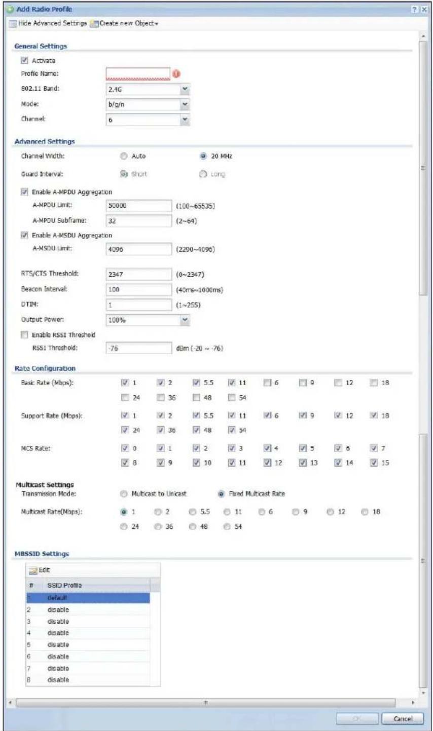
text_image
Add Radio Profile Hide Advanced Settings Create new Object* General Settings ✓ Activata Profile Name: 1 802.11 Band: 2.4G Mode: b/g/n Channel: 6 Advanced Settings Channel Width: Auto 20 MHz Guard Interval: Short Long ✓ Enable A-MPDU Aggregation A-MPDU Limit: 50000 (100~65535) A-MPDU Subframe: 32 (2~64) ✓ Enable A-MSDU Aggregation A-MSDU Limit: 4096 (2290~4096) RTS/CTS Threshold: 2347 (0~2347) Beacon Interval: 100 (40ms~1000ms) DTIM: 1 (1~255) Output Power: 100% □ Enable RSSI Threshold RSSI Threshold: -76 d8m (-20 ~ -76) Rate Configuration Basic Rate (Mbps): ✓ 1 ✓ 2 ✓ 5.5 ✓ 11 ☐ 6 ☐ 9 ☐ 12 ☐ 18 ☐ 24 ☐ 36 ☐ 48 ☐ 54 Support Rate (Mbps): ✓ 1 ✓ 2 ✓ 5.5 ✓ 11 ✓ 6 ✓ 9 ✓ 12 ✓ 18 ✓ 24 ✓ 36 ✓ 48 ✓ 54 NCS Rate: ✓ 0 ✓ 1 ✓ 2 ✓ 3 ✓ 4 ✓ 5 ✓ 6 ✓ 7 ✓ 8 ✓ 9 ✓ 10 ✓ 11 ✓ 12 ✓ 13 ✓ 14 ✓ 15 Multicast Settings Transmission Mode: Multicast to Unicast Fixed Multicast Rate Multicast Rate(Mbps): ✓ 1 ✓ 2 ✓ 5.5 ☐ 11 ☐ 6 ☐ 9 ☐ 12 ☐ 18 ☐ 24 ☐ 36 ☐ 48 ☐ 54 MBSSID SettingsSSID Profile
default 2 disable 3 disable 4 disable 5 disable 6 disable 7 disable 8 disableThe following table describes the labels in this screen.
Table 153 Configuration > Object > AP Profile > Radio > Add/Edit
| LABEL DESCRIPTION | |
| Hide / Show Advanced Settings | Click this to hide or show the Advanced Settings in this window. |
| Create New Object Select | Select an item from this menu to create a new object of that type. Any objects created in this way are automatically linked to this radio profile. |
| General Settings | |
| Activate Select this option to make this profile active. | |
| Profile Name | Enter up to 31 alphanumeric characters to be used as this profile's name. Spaces and underscores are allowed. |
| 802.11 Band Select | the wireless band which this radio profile should use.2.4 GHz is the frequency used by IEEE 802.11b/g/n wireless clients.5 GHz is the frequency used by IEEE 802.11a/n wireless clients. |
| Mode Select how to let wireless clients connect to the AP.When using the 2.4 GHz band, select b/ g to let IEEE 802.11b and IEEE 802.11g compliant WLAN devices associate with the AP.When using the 2.4 GHz band, select b/ g/ n to let IEEE 802.11b, IEEE 802.11g, and IEEE 802.11n compliant WLAN devices associate with the AP.When using the 5 GHz band, select a to let only IEEE 802.11a compliant WLAN devices associate with the AP.When using the 5 GHz band, select a/ n to let IEEE 802.11a and IEEE 802.11n compliant WLAN devices associate with the AP. | |
| Channel Select the wireless channel which this radio profile should use.It is recommended that you choose the channel least in use by other APs in the region where this profile will be implemented. This will reduce the amount of interference between wireless clients and the AP to which this profile is assigned.Some 5 GHz channels include the label indoor use only. These are for use with an indoor AP only. Do not use them with an outdoor AP. | |
| Advanced Settings | |
| Channel Width Select the channel bandwidth you want to use for your wireless network.Select Auto to allow the UAG to adjust the channel bandwidth to 40 MHz or 20 MHz depending on network conditions.Select 20 MHz if you want to lessen radio interference with other wireless devices in your neighborhood. | |
| Guard Interval | Set the guard interval for this radio profile to either short or long.The guard interval is the gap introduced between data transmission from users in order to reduce interference. Reducing the interval increases data transfer rates but also increases interference. Increasing the interval reduces data transfer rates but also reduces interference. |
| Enable A-MPDU Aggregation | Select this to enable A-MPDU aggregation.Message Protocol Data Unit (MPDU) aggregation collects Ethernet frames along with their 802.11n headers and wraps them in a 802.11n MAC header. This method is useful for increasing bandwidth throughput in environments that are prone to high error rates. |
| A-MPDU Limit Enter the maximum frame size to be aggregated. | |
| LABEL DESCRIPTION | |
| A-MPDU Subframe | Enter the maximum number of frames to be aggregated each time. |
| Enable A-MSDU Aggregation | Select this to enable A-MSDU aggregation.Mac Service Data Unit (MSDU) aggregation collects Ethernet frames without any of their 802.11n headers and wraps the header-less payload in a single 802.11n MAC header. This method is useful for increasing bandwidth throughput. It is also more efficient than A-MPDU except in environments that are prone to high error rates. |
| A-MSDU Limit Enter the maximum frame size to be aggregated. | |
| Disable-Channel Switch for DFS | This field is available when you select 5G in the 802.11 Band field.DFS (dynamic frequency selection) allows an AP to detect other devices in the same channel. If there is another device using the same channel, the AP changes to a different channel, so that it can avoid interference with radar systems or other wireless networks.Select this option to disable DFS on the AP. |
| RTS/CTS Threshold | Use RTS/CTS to reduce data collisions on the wireless network if you have wireless clients that are associated with the same AP but out of range of one another. When enabled, a wireless client sends an RTS (Request To Send) and then waits for a CTS (Clear To Send) before it transmits. This stops wireless clients from transmitting packets at the same time (and causing data collisions).A wireless client sends an RTS for all packets larger than the number (of bytes) that you enter here. Set the RTS/CTS equal to or higher than the fragmentation threshold to turn RTS/CTS off. |
| Beacon Interval | When a wirelessly networked device sends a beacon, it includes with it a beacon interval. This specifies the time period before the device sends the beacon again. The interval tells receiving devices on the network how long they can wait in low-power mode before waking up to handle the beacon. A high value helps save current consumption of the access point. |
| DTIM | Delivery Traffic Indication Message (DTIM) is the time period after which broadcast and multicast packets are transmitted to mobile clients in the Active Power Management mode. A high DTIM value can cause clients to lose connectivity with the network. This value can be set from 1 to 255. |
| Output Power Set | the output power of the AP in this field. If there is a high density of APs in an area, decrease the output power of the NWA5160N to reduce interference with other APs. Select one of the following 100%, 50%, 25%, or 12.5%. See the product specifications for more information on your UAG's output power.Note: Reducing the output power also reduces the UAG's effective broadcast radius. |
| Enable RSSI Threshold | Use the Received Signal Strength Indication (RSSI) threshold to ensure wireless clients receive good throughput. This allows only wireless clients with a strong signal to connect to the AP.Select the check box and set a minimum client signal strength for connecting to the AP.-20 dBm is the strongest signal you can require and -76 is the weakest.Clear the check box to not require wireless clients to have a minimum signal strength to connect to the AP. |
| Rate Configuration | This section controls the data rates permitted for clients.For each Rate, select a rate option from its list. The rates are:Basic Rate (Mbps) - Set the basic rate configuration in Mbps.Support Rate (Mbps) - Set the support rate configuration in Mbps.MCS Rate - Set the MCS rate configuration. IEEE 802.11n supports many different data rates which are called MCS rates. MCS stands for Modulation and Coding Scheme. This is an 802.11n feature that increases the wireless network performance in terms of throughput. |
| Multicast Settings | Use this section to set a transmission mode and maximum rate for multicast traffic. |
| Transmission Mode | Set how the AP handles multicast traffic.Select Multicast to Unicast to broadcast wireless multicast traffic to all of the wireless clients as unicast traffic. Unicast traffic dynamically changes the data rate based on the application's bandwidth requirements. The retransmit mechanism of unicast traffic provides more reliable transmission of the multicast traffic, although it also produces duplicate packets.Select Fixed Multicast Rate to send wireless multicast traffic at a single data rate. You must know the multicast application's bandwidth requirements and set it in the following field. |
| Multicast Rate (Mbps) | If you set the multicast transmission mode to fixed multicast rate, set the data rate for multicast traffic here. For example, to deploy 4 Mbps video, select a fixed multicast rate higher than 4 Mbps. |
| MBSSID Settings | This section allows you to associate an SSID profile with the radio profile. |
| Edit | Select and SSID and click this button to reassign it. The selected SSID becomes editable immediately upon clicking. |
| SSID Profile | Indicates which SSID profile is associated with this radio profile. |
| OK | Click OK to save your changes back to the UAG. |
| Cancel | Click Cancel to exit this screen without saving your changes. |
33.3 SSID Screen
The SSID screens allow you to configure three different types of profiles for your networked APs: an SSID list, which can assign specific SSID configurations to your APs; a security list, which can assign specific encryption methods to the APs when allowing wireless clients to connect to them; and a MAC filter list, which can limit connections to an AP based on wireless clients MAC addresses.
33.3.1 SSID List
This screen allows you to create and manage SSID configurations that can be used by the APs. An SSID, or Service Set IDentifier, is basically the name of the wireless network to which a wireless client can connect. The SSID appears as readable text to any device capable of scanning for wireless frequencies (such as the Wi-Fi adapter in a laptop), and is displayed as the wireless network name when a person makes a connection to it.
To access this screen click Configuration > Object > AP Profile > SSI D.
Note: You can have a maximum of 64 SSID profiles on the UAG.
Figure 227 Configuration > Object > AP Profile > SSID > SSID List
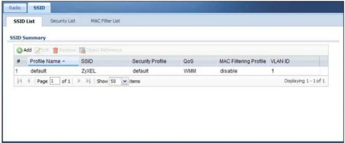
text_image
Radio SSID SSID List Security List MAC Filter List SSID Summary Add Edit Review Object ReferenceProfile Name SSID Security Profile QoS MAC Filtering Profile VLAN ID
1 default ZyXEL default WMM disable 1 Page 1 of 1 Show 50 items Displaying 1 - 1 of 1The following table describes the labels in this screen.
Table 154 Configuration > Object > AP Profile > SSID > SSID List
| LABEL DESCRIPTION | |
| Add Click this to add a new SSID profile. | |
| Edit Click this to edit the selected SSID profile. | |
| Remove Click this to remove the selected SSID profile. | |
| Object Reference | Click this to view which other objects are linked to the selected SSID profile (for example, radio profile). |
| # This field is a sequential value, and it is not associated with a specific profile. | |
| Profile Name This field indicates the name assigned to the SSID profile. | |
| SSID This field indicates the SSID name as it appears to wireless clients. | |
| Security Profile | This field indicates which (if any) security profile is associated with the SSID profile. |
| QoS This field indicates the QoS type associated with the SSID profile. | |
| MAC Filtering Profile | This field indicates which (if any) MAC Filter Profile is associated with the SSID profile. |
| VLAN ID This field | indicates the VLAN ID associated with the SSID profile. |
33.3.2 Add/Edit SSID Profile
This screen allows you to create a new SSID profile or edit an existing one. To access this screen, click the Add button or select an SSID profile from the list and click the Edit button.
Figure 228 Configuration > Object > AP Profile > SSID > SSID List > Add/Edit
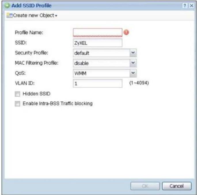
text_image
Add SSID Profile Create new Object Profile Name: SSID: ZyXEL Security Profile: default MAC Filtering Profile: disable QoS: WMM VLAN ID: 1 (1~4094) Hidden SSID Enable Intra-BSS Traffic blocking OK CancelThe following table describes the labels in this screen.
Table 155 Configuration > Object > AP Profile > SSID > SSID List > Add/Edit
| LABEL DESCRIPTION | |
| Create new Object | Select an object type from the list to create a new one associated with this SSID profile. |
| Profile Name | Enter up to 31 alphanumeric characters for the profile name. This name is only visible in the Web Configurator and is only for management purposes. Spaces and underscores are allowed. |
| SSID | Enter the SSID name for this profile. This is the name visible on the network to wireless clients. Enter up to 32 characters, spaces and underscores are allowed. |
| Security Profile | Select a security profile from this list to associate with this SSID. If none exist, you can use the Create new Object menu to create one.Note: It is highly recommended that you create security profiles for all of your SSIDs to enhance your network security. |
| MAC Filtering Profile | Select a MAC filtering profile from the list to associate with this SSID. If none exist, you can sue the Create new Object menu to create one.MAC filtering allows you to limit the wireless clients connecting to your network through a particular SSID by wireless client MAC addresses. Any clients that have MAC addresses not in the MAC filtering profile of allowed addresses are denied connections.The disable setting means no MAC filtering is used. |
| LABEL DESCRIPTION | |
| QoS Select a Qual | ty of Service (QoS) access category to associate with this SSID. Access categories minimize the delay of data packets across a wireless network. Certain categories, such as video or voice, are given a higher priority due to the time sensitive nature of their data packets.QoS access categories are as follows:disable:Turns off QoS for this SSID. All data packets are treated equally and not tagged with access categories.WMM:Enables automatic tagging of data packets. The UAG assigns access categories to the SSID by examining data as it passes through it and making a best guess effort. If something looks like video traffic, for instance, it is tagged as such.WMM_VOICE:All wireless traffic to the SSID is tagged as voice data. This is recommended if an SSID is used for activities like placing and receiving VoIP phone calls.WMM_VIDEO:All wireless traffic to the SSID is tagged as video data. This is recommended for activities like video conferencing.WMM_BEST_EFFORT:All wireless traffic to the SSID is tagged as "best effort," meaning the data travels the best route it can without displacing higher priority traffic. This is good for activities that do not require the best bandwidth throughput, such as surfing the Internet.WMM_BACKGROUND:All wireless traffic to the SSID is tagged as low priority or "background traffic", meaning all other access categories take precedence over this one. If traffic from an SSID does not have strict throughput requirements, then this access category is recommended. For example, an SSID that only has network printers connected to it. |
| VLAN ID | Enter the VLAN ID that will be used to tag all traffic originating from this SSID if the VLAN is different from the native VLAN. |
| Hidden SSID | Select this if you want to "hide" your SSID from wireless clients. This tells any wireless clients in the vicinity of the AP using this SSID profile not to display its SSID name as a potential connection. Not all wireless clients respect this flag and display it anyway.When an SSID is "hidden" and a wireless client cannot see it, the only way you can connect to the SSID is by manually entering the SSID name in your wireless connection setup screen(s) (these vary by client, client connectivity software, and operating system). |
| Enable Intra-BSS Traffic Blocking | Select this option to prevent crossover traffic from within the same SSID. |
| OK | Click OKto save your changes back to the UAG. |
| Cancel | Click Cancelto exit this screen without saving your changes. |
33.3.3 Security List
This screen allows you to manage wireless security configurations that can be used by your SSIDs. Wireless security is implemented strictly between the AP broadcasting the SSID and the stations that are connected to it.
To access this screen click Configuration > Object > AP Profile > SSID > Security List.
Note: You can have a maximum of 64 security profiles on the UAG.
Figure 229 Configuration > Object > AP Profile > SSID > Security List
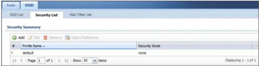
text_image
Radio SSID SSID List Security List MAC Filter List Security Summary Add Edit Remove Object ReferenceProfile Name Security Mode
1 default none Page 1 of 1 Show 50 items Displaying 1 - 1 of 1The following table describes the labels in this screen.
Table 156 Configuration > Object > AP Profile > SSID > Security List
| LABEL DESCRIPTION | |
| Add Click this to add a new security profile. | |
| Edit Click this to edit the selected security profile. | |
| Remove Click this to remove the selected security profile. | |
| Object Reference | Click this to view which other objects are linked to the selected security profile (for example, SSID profile). |
| # This field is a sequential value, and it is not associated with a specific profile. | |
| Profile Name This field indicates the name assigned to the security profile. | |
| Security Mode This field indicates this profile's security mode (if any). | |
33.3.4 Add/Edit Security Profile
This screen allows you to create a new security profile or edit an existing one. To access this screen, click the Add button or select a security profile from the list and click the Edit button.
Note: This screen's options change based on the Security Mode selected. Only the default screen is displayed here.
Figure 230 Configuration > Object > AP Profile > SSID > Security List > Add/Edit

text_image
Add Security Profile General Settings Profile Name: Security Mode: wpa2-mix Radius Settings Radius Server Type: External Primary Radius Server Activate Radius Server IP Address: Radius Server Port: (1-65535) Radius Server Secret: Secondary Radius Server Activate Radius Server IP Address: Radius Server Port: (1-65535) Radius Server Secret: Authentication Settings 802.1X ReAuthentication Timer: 0 (30~30000 seconds, 0 is unlimited) PSK Pre-Shared Key: Cipher Type: aes Idle timeout: 300 (30-30000 seconds) Group Key Update Timer: 1800 (30-30000 seconds) Pre-Authentication: Enable OK CancelThe following table describes the labels in this screen.
Table 157 Configuration > Object > AP Profile > SSID > Security List > Add/Edit
| LABEL DESCRIPTION | |
| Profile Name | Enter up to 31 alphanumeric characters for the profile name. This name is only visible in the Web Configurator and is only for management purposes. Spaces and underscores are allowed. |
| Security Mode | Select a security mode from the list: wep, wpa, wpa2, or wpa2-mix. |
| LABEL | DESCRIPTION |
| Radius Server Type | Select Internal to use the UAG's internal authentication database, or External to use an external RADIUS server for authentication. |
| Primary / Secondary Radius Server Activate | Select this to have the UAG use the specified RADIUS server. |
| Radius Server IP Address | Enter the IP address of the RADIUS server to be used for authentication. |
| Radius Server Port | Enter the port number of the RADIUS server to be used for authentication. |
| Radius Server Secret | Enter the shared secret password of the RADIUS server to be used for authentication. |
| 802.1X Select this to | enable 802.1x secure authentication. |
| Auth. Method | This field is available only when you set the RADIUS server type to Internal.Select an authentication method if you have created any in the Configuration > Object > Auth. Method screen. |
| Reauthentication Timer | Enter the interval (in seconds) between authentication requests. Enter a 0 for unlimited requests. |
| The following fields are available if you set Security Mode to wep. | |
| Idle Timeout | Enter the idle interval (in seconds) that a client can be idle before authentication is discontinued. |
| Authentication Type | Select a WEP authentication method. Choices are Open or Share key. |
| Key Length Select the bit-length of the encryption key to be used in WEP connections.If you select WEP-64:Enter 10 hexadecimal digits in the range of “A-F”, “a-f” and “0-9” (for example, 0x11AA22BB33) for each Key used.orEnter 5 ASCII characters (case sensitive) ranging from “a-z”, “A-Z” and “0-9” (for example, MyKey) for each Key used.If you select WEP-128:Enter 26 hexadecimal digits in the range of “A-F”, “a-f” and “0-9” (for example, 0x00112233445566778899AABBCC) for each Key used.orEnter 13 ASCII characters (case sensitive) ranging from “a-z”, “A-Z” and “0-9” (for example, MyKey12345678) for each Key used. | |
| Key 1~4 | Based on your Key Length selection, enter the appropriate length hexadecimal or ASCII key. |
| The following fields are available if you set Security Mode to wpa, wpa2 or wpa2-mix. | |
| PSK Select this option to use a Pre-Shared Key with WPA encryption. | |
| Pre-Shared Key | Enter a pre-shared key of between 8 and 63 case-sensitive ASCII characters (including spaces and symbols) or 64 hexadecimal characters. |
| Cipher Type | Select an encryption cipher type from the list.auto - This automatically chooses the best available cipher based on the cipher in use by the wireless client that is attempting to make a connection.tkip - This is the Temporal Key Integrity Protocol encryption method added later to the WEP encryption protocol to further secure. Not all wireless clients may support this.aes - This is the Advanced Encryption Standard encryption method. It is a more recent development over TKIP and considerably more robust. Not all wireless clients may support this. |
| LABEL DESCRIPTION | |
| Idle Timeout | Enter the idle interval (in seconds) that a client can be idle before authentication is discontinued. |
| Group Key Update Timer | Enter the interval (in seconds) at which the AP updates the group WPA encryption key. |
| Pre-Authentication | This field is available only when you set Security Mode to wpa2 or wpa2-mix and enable 802.1x authentication.Enable or Disable pre-authentication to allow the AP to send authentication information to other APs on the network, allowing connected wireless clients to switch APs without having to re-authenticate their network connection. |
| OK | Click OK to save your changes back to the UAG. |
| Cancel | Click Cancel to exit this screen without saving your changes. |
33.3.5 MAC Filter List
This screen allows you to create and manage security configurations that can be used by your SSIDs. To access this screen click Configuration > Object > AP Profile > SSID > MAC Filter List.
Note: You can have a maximum of 32 MAC filtering profiles on the UAG.
Figure 231 Configuration > Object > AP Profile > SSID > MAC Filter List
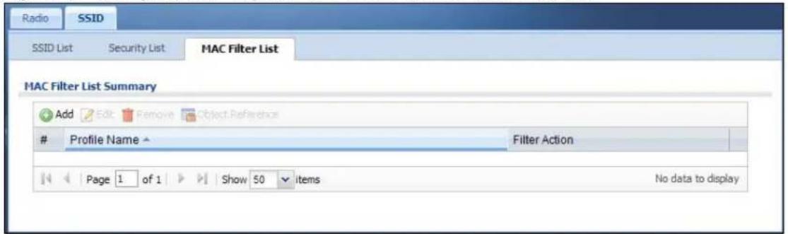
text_image
Radio SSID SSID List Security List MAC Filter List MAC Filter List Summary Add Edit Remove Object ReferenceProfile Name
Filter Action Page 1 of 1 Show 50 items No data to displayThe following table describes the labels in this screen.
Table 158 Configuration > Object > AP Profile > SSID > MAC Filter List
| LABEL DESCRIPTION | |
| Add Click this to add a new MAC filtering profile. | |
| Edit Click this to edit the selected MAC filtering profile. | |
| Remove | Click this to remove the selected MAC filtering profile. |
| Object Reference | Click this to view which other objects are linked to the selected MAC filtering profile (for example, SSID profile). |
| # This field is a sequential value, and it is not associated with a specific profile. | |
| Profile Name This field indicates the name assigned to the MAC filtering profile. | |
| Filter Action This field indicates this profile's filter action (if any). | |
33.3.6 Add/Edit MAC Filter Profile
This screen allows you to create a new MAC filtering profile or edit an existing one. To access this screen, click the Add button or select a MAC filter profile from the list and click the Edit button.
Figure 232 Configuration > Object > AP Profile > SSID > MAC Filter List > Add/Edit
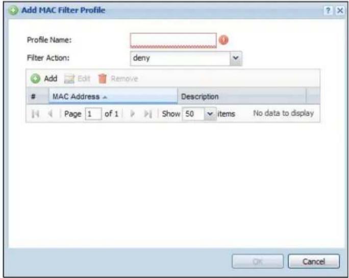
text_image
Add MAC Filter Profile Profile Name: Filter Action: deny Add Edit RemoveMAC Address Description
Page 1 of 1 Show 50 items No data to display OK CancelThe following table describes the labels in this screen.
Table 159 Configuration > Object > AP Profile > SSID > MAC Filter List > Add/Edit
| LABEL DESCRIPTION | |
| Profile Name | Enter up to 31 alphanumeric characters for the profile name. This name is only visible in the Web Configurator and is only for management purposes. Spaces and underscores are allowed. |
| Filter Action | Select allow to permit the wireless client with the MAC addresses in this profile to connect to the network through the associated SSID; select deny to block the wireless clients with the specified MAC addresses. |
| Add Click this to add a MAC address to the profile's list. | |
| Edit Click this to edit the selected MAC address in the profile's list. | |
| Remove Click this to remove the selected MAC address from the profile's list. | |
| # | This field is a sequential value, and it is not associated with a specific profile. |
| MAC Address This field specifies a MAC address associated with this profile. | |
| Description | This field displays a description for the MAC address associated with this profile. You can click the description to make it editable. Enter up to 60 characters, spaces and underscores allowed. |
| OK | Click OK to save your changes back to the UAG. |
| Cancel | Click Cancel to exit this screen without saving your changes. |
34.1 Overview
Address objects can represent a single IP address or a range of IP addresses. Address groups are composed of address objects and other address groups.
34.1.1 What You Can Do in this Chapter
- The Address screen (Section 34.2 on page 354) provides a summary of all addresses in the UAG. Use the Address Add/ Edit screen to create a new address or edit an existing one.
- Use the Address Group summary screen (Section 34.3 on page 356) and the Address Group Add/ Edit screen, to maintain address groups in the UAG.
34.1.2 What You Need To Know
Address objects and address groups are used in dynamic routes, firewall rules, and VPN 1-1 mapping profiles. Please see the respective sections for more information about how address objects and address groups are used in each one.
Address groups are composed of address objects and address groups. The sequence of members in the address group is not important.
34.2 Address Summary Screen
The address screens are used to create, maintain, and remove addresses. There are the types of address objects.
- HOST - a host address is defined by an IP Address.
- RANGE - a range address is defined by a Starting IP Address and an Ending IP Address.
- SUBNET - a network address is defined by a Network IP address and Netmask subnet mask.
The Address screen provides a summary of all addresses in the UAG. To access this screen, click Configuration > Object > Address > Address. Click a column's heading cell to sort the table entries by that column's criteria. Click the heading cell again to reverse the sort order.
Figure 233 Configuration > Object > Address > Address

text_image
Address Address Group Configuration Add Edit Remove Object ReferenceName Type IPv4 Address
1 LAN1_SUBNET INTERFACE SUBNET Ian1-172.16.0.0/16 2 LAN2_SUBNET INTERFACE SUBNET Ian2-172.17.0.0/16 Page 1 of 1 Show 50 items Displaying 1 - 2 of 2The following table describes the labels in this screen. See Section 34.2.1 on page 355 for more information as well.
Table 160 Configuration > Object > Address > Address
| LABEL DESCRIPTION | |
| Configuration | |
| Add Click this to create a new entry. | |
| Edit | Double-click an entry or select it and click Edit to be able to modify the entry's settings. |
| Remove | To remove an entry, select it and click Remove. The UAG confirms you want to remove it before doing so. |
| Object Reference | Select an entry and click Object Reference to open a screen that shows which settings use the entry. See Section 10.3.2 on page 129 for an example. |
| # This field is a sequential value, and it is not associated with a specific address. | |
| Name This field displays the configured name of each address object. | |
| Type | This field displays the type of each address object. "INTERFACE" means the object uses the settings of one of the UAG's interfaces. |
| IPv4 Address | This field displays the IPv4 addresses represented by each address object. If the object's settings are based on one of the UAG's interfaces, the name of the interface displays first followed by the object's current address settings. |
34.2.1 Address Add/Edit Screen
The Configuration > Object > Address Add/ Edit screen allows you to create a new address or edit an existing one. To access this screen, go to the Address screen (see Section 34.2 on page 354), and either click the Add icon or select an entry and click the Edit icon in the Configuration section.
Figure 234 IPv4 Address Configuration > Add/Edit

text_image
Add Address Rule Name: Address Type: HOST IP Address: 0.0.0.0 OK CancelThe following table describes the labels in this screen.
Table 161 IPv4 Address Configuration > Add/Edit
| LABEL DESCRIPTION | |
| Name | Type the name used to refer to the address. You may use 1-31 alphanumeric characters, underscores( ), or dashes (-), but the first character cannot be a number. This value is case-sensitive. |
| Address Type | Select the type of address you want to create. Choices are:HOST, RANGE, SUBNET, INTERFACE IP, INTERFACE SUBNET, and INTERFACE GATEWAY.Note: The UAG automatically updates address objects that are based on an interface's IP address, subnet, or gateway if the interface's IP address settings change. For example, if you change lan1's IP address, the UAG automatically updates the corresponding interface-based, LAN subnet address object. |
| IP Address | This field is only available if theAddress Typeis HOST. This field cannot be blank. Enter the IP address that this address object represents. |
| Starting IP Address | This field is only available if theAddress Typeis RANGE. This field cannot be blank. Enter the beginning of the range of IP addresses that this address object represents. |
| Ending IP Address | This field is only available if theAddress Typeis RANGE. This field cannot be blank. Enter the end of the range of IP address that this address object represents. |
| Network | This field is only available if theAddress Typeis SUBNET, in which case this field cannot be blank. Enter the IP address of the network that this address object represents. |
| Netmask | This field is only available if theAddress Typeis SUBNET, in which case this field cannot be blank. Enter the subnet mask of the network that this address object represents. Use dotted decimal format. |
| Interface | If you selectedINTERFACE IP, INTERFACE SUBNET, or INTERFACE GATEWAYas the Address Type, use this field to select the interface of the network that this address object represents. |
| OK | ClickOKto save your changes back to the UAG. |
| Cancel | ClickCancelto exit this screen without saving your changes. |
34.3 Address Group Summary Screen
The Address Group screen provides a summary of all address groups. To access this screen, click Configuration > Object > Address > Address Group. Click a column's heading cell to sort the table entries by that column's criteria. Click the heading cell again to reverse the sort order.
Figure 235 Configuration > Object > Address > Address Group

text_image
Address Address Group Configuration Add Edit Remove Object ReferenceName Description
1 test Page 1 of 1 Show 50 items Displaying 1 - 1 of 1The following table describes the labels in this screen. See Section 34.3.1 on page 357 for more information as well.
Table 162 Configuration > Object > Address > Address Group
| LABEL DESCRIPTION | |
| Configuration | |
| Add Click this to create a new entry. | |
| Edit | Double-click an entry or select it and click Edit to be able to modify the entry's settings. |
| Remove | To remove an entry, select it and click Remove. The UAG confirms you want to remove it before doing so. |
| Object Reference | Select an entry and click Object Reference to open a screen that shows which settings use the entry. See Section 10.3.2 on page 129 for an example. |
| # | This field is a sequential value, and it is not associated with a specific address group. |
| Name This field displays the name of each address group. | |
| Description This field displays the description of each address group, if any. | |
34.3.1 Address Group Add/Edit Screen
The Address Group Add/ Edit screen allows you to create a new address group or edit an existing one. To access this screen, go to the Address Group screen (see Section 34.3 on page 356), and either click the Add icon or select an entry and click the Edit icon in the Configuration section.
Figure 236 Configuration > Object > Address > Address Group > Add/Edit
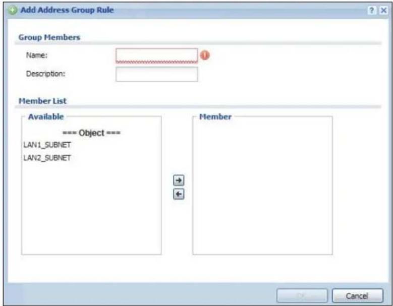
text_image
Add Address Group Rule Group Members Name: Description: Member List Available === Object === LAN1_SUBNET LAN2_SUBNET Member CancelThe following table describes the labels in this screen.
Table 163 Configuration > Object > Address > Address Group > Add/Edit
| LABEL DESCRIPTION | |
| Name Enter a name for the address group. You may use 1-31 alphanumeric characters, underscores( ), or dashes (-), but the first character cannot be a number. This value is case-sensitive. | |
| Description | This field displays the description of each address group, if any. You can use up to 60 characters, punctuation marks, and spaces. |
| Member List | The Member list displays the names of the address and address group objects that have been added to the address group. The order of members is not important.Select items from the Available list that you want to be members and move them to the Member list. You can double-click a single entry to move it or use the [Shift] or [Ctrl] key to select multiple entries and use the arrow button to move them.Move any members you do not want included to the Available list. |
| OK | Click OK to save your changes back to the UAG. |
| Cancel | Click Cancel to exit this screen without saving your changes. |
35.1 Overview
Use service objects to define TCP applications, UDP applications, and ICMP messages. You can also create service groups to refer to multiple service objects in other features.
35.1.1 What You Can Do in this Chapter
- Use the Service screens (Section 35.2 on page 360) to view and configure the UAG's list of services and their definitions.
- Use the Service Group screens (Section 35.2 on page 360) to view and configure the UAG's list of service groups.
35.1.2 What You Need to Know
IP Protocols
IP protocols are based on the eight-bit protocol field in the IP header. This field represents the next-level protocol that is sent in this packet. This section discusses three of the most common IP protocols.
Computers use Transmission Control Protocol (TCP, IP protocol 6) and User Datagram Protocol (UDP, IP protocol 17) to exchange data with each other. TCP guarantees reliable delivery but is slower and more complex. Some uses are FTP, HTTP, SMTP, and TELNET. UDP is simpler and faster but is less reliable. Some uses are DHCP, DNS, RIP, and SNMP.
TCP creates connections between computers to exchange data. Once the connection is established, the computers exchange data. If data arrives out of sequence or is missing, TCP puts it in sequence or waits for the data to be re-transmitted. Then, the connection is terminated.
In contrast, computers use UDP to send short messages to each other. There is no guarantee that the messages arrive in sequence or that the messages arrive at all.
Both TCP and UDP use ports to identify the source and destination. Each port is a 16-bit number. Some port numbers have been standardized and are used by low-level system processes; many others have no particular meaning.
Unlike TCP and UDP, Internet Control Message Protocol (ICMP, IP protocol 1) is mainly used to send error messages or to investigate problems. For example, ICMP is used to send the response if a computer cannot be reached. Another use is ping. ICMP does not guarantee delivery, but networks often treat ICMP messages differently, sometimes looking at the message itself to decide where to send it.
Service Objects and Service Groups
Use service objects to define IP protocols.
- TCP applications
- UDP applications
- ICMP messages
- user-defined services (for other types of IP protocols)
These objects are used in policy routes, and firewall rules.
Use service groups when you want to create the same rule for several services, instead of creating separate rules for each service. Service groups may consist of services and other service groups. The sequence of members in the service group is not important.
35.2 The Service Summary Screen
The Service summary screen provides a summary of all services and their definitions. In addition, this screen allows you to add, edit, and remove services.
To access this screen, log in to the Web Configurator, and click Configuration > Object > Service > Service. Click a column's heading cell to sort the table entries by that column's criteria. Click the heading cell again to reverse the sort order.
Figure 237 Configuration > Object > Service > Service
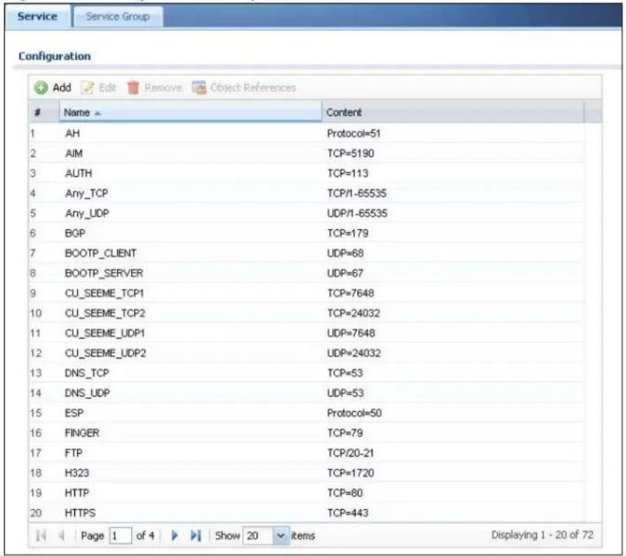
text_image
Service Service Group Configuration Add Edit Remove Object ReferencesName > Content
1 AH Protocol=51 2 AIM TCP=5190 3 AUTH TCP=113 4 Any_TCP TCP/1-65535 5 Any_UDP UDP/1-65535 6 BGP TCP=179 7 BOOTP_CLIENT UDP=68 8 BOOTP_SERVER UDP=67 9 CU_SEEME_TCP1 TCP=7648 10 CU_SEEME_TCP2 TCP=24032 11 CU_SEEME_UDP1 UDP=7648 12 CU_SEEME_UDP2 UDP=24032 13 DNS_TCP TCP=53 14 DNS_UDP UDP=53 15 ESP Protocol=50 16 FINGER TCP=79 17 FTP TCP/20-21 18 H323 TCP=1720 19 HTTP TCP=80 20 HTTPS TCP=443 Page 1 of 4 Show 20 Items Displaying 1 - 20 of 72The following table describes the labels in this screen.
Table 164 Configuration > Object > Service > Service
| LABEL DESCRIPTION | |
| Add Click this to create a new entry. | |
| Edit | Double-click an entry or select it and click Edit to be able to modify the entry's settings. |
| Remove | To remove an entry, select it and click Remove. The UAG confirms you want to remove it before doing so. |
| Object Reference | Select an entry and click Object Reference to open a screen that shows which settings use the entry. See Section 10.3.2 on page 129 for an example. |
| # This field is a sequential value, and it is not associated with a specific service. | |
| Name This field displays the name of each service. | |
| Content This field displays a description of each service. | |
35.2.1 The Service Add/Edit Screen
The Service Add/ Edit screen allows you to create a new service or edit an existing one. To access this screen, go to the Service screen (see Section 35.2 on page 360), and either click the Add icon or select an entry and click the Edit icon.
Figure 238 Configuration > Object > Service > Service > Add/Edit
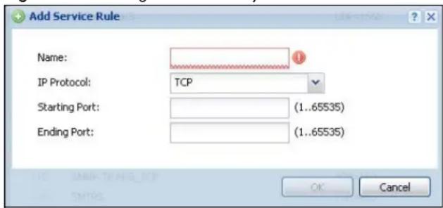
text_image
Add Service Rule Name: IP Protocol: TCP Starting Port: (1..65535) Ending Port: (1..65535) OK CancelThe following table describes the labels in this screen.
Table 165 Configuration > Object > Service > Service > Add/Edit
| LABEL DESCRIPTION | |
| Name | Type the name used to refer to the service. You may use 1-31 alphanumeric characters, underscores( ), or dashes (-), but the first character cannot be a number. This value is case-sensitive. |
| IP Protocol | Select the protocol the service uses. Choices are: TCP, UDP, ICMP, and User Defined. |
| Starting Port Ending Port | This field appears if the IP Protocol is TCP or UDP. Specify the port number(s) used by this service. If you fill in one of these fields, the service uses that port. If you fill in both fields, the service uses the range of ports. |
| ICMP Type | This field appears if the IP Protocol is ICMP.Select the ICMP message used by this service. This field displays the message text, not the message number. |
| IP Protocol Number | This field appears if the IP Protocol is User Defined.Enter the number of the next-level protocol (IP protocol). Allowed values are 1 - 255. |
| OK | Click OK to save your changes back to the UAG. |
| Cancel | Click Cancel to exit this screen without saving your changes. |
35.3 The Service Group Summary Screen
The Service Group summary screen provides a summary of all service groups. In addition, this screen allows you to add, edit, and remove service groups.
To access this screen, log in to the Web Configurator, and click Configuration > Object > Service > Service Group.
Figure 239 Configuration > Object > Service > Service Group
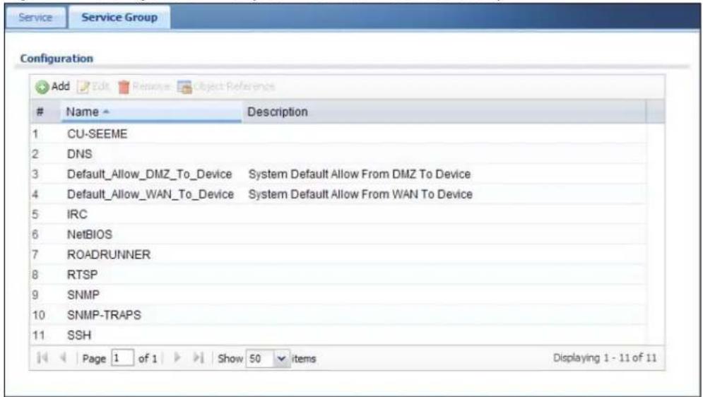
text_image
Service Service Group Configuration Add Edit Remove Object ReferenceName Description
1 CU-SEEME 2 DNS 3 Default_Allow_DMZ_To_Device System Default Allow From DMZ To Device 4 Default_Allow_WAN_To_Device System Default Allow From WAN To Device 5 IRC 6 NetBIOS 7 ROADRUNNER 8 RTSP 9 SNMP 10 SNMP-TRAPS 11 SSH Page 1 of 1 Show 50 items Displaying 1 - 11 of 11The following table describes the labels in this screen. See Section 35.3.1 on page 362 for more information as well.
Table 166 Configuration > Object > Service > Service Group
| LABEL DESCRIPTION | |
| Add Click this to create a new entry. | |
| Edit | Double-click an entry or select it and click Edit to be able to modify the entry's settings. |
| Remove | To remove an entry, select it and click Remove. The UAG confirms you want to remove it before doing so. |
| Object Reference | Select an entry and click Object Reference to open a screen that shows which settings use the entry. See Section 10.3.2 on page 129 for an example. |
| # | This field is a sequential value, and it is not associated with a specific service group. |
| Name This field displays the name of each service group.By default, the UAG uses services starting with "Default_Allow_" in the firewall rules to allow certain services to connect to the UAG. | |
| Description This field displays the description of each service group, if any. | |
35.3.1 The Service Group Add/Edit Screen
The Service Group Add/ Edit screen allows you to create a new service group or edit an existing one. To access this screen, go to the Service Group screen (see Section 35.3 on page 362), and either click the Add icon or select an entry and click the Edit icon.
Figure 240 Configuration > Object > Service > Service Group > Add/Edit

text_image
Add Service Group Rule Configuration Name: Description: Member List Available === Object === Any_UDP Any_TCP AH AIM NEW_ICQ AUTH BGP BOOTP_CLIENT BOOTP_SERVER Member OK CancelThe following table describes the labels in this screen.
Table 167 Configuration > Object > Service > Service Group > Add/Edit
| LABEL DESCRIPTION | |
| Name Enter the name of the service group. You may use 1-31 alphanumeric characters, underscores( ), or dashes (-), but the first character cannot be a number. This value is case-sensitive. | |
| Description | Enter a description of the service group, if any. You can use up to 60 printable ASCII characters. |
| Member List | The Member list displays the names of the service and service group objects that have been added to the service group. The order of members is not important.Select items from the Available list that you want to be members and move them to the Member list. You can double-click a single entry to move it or use the [Shift] or [Ctrl] key to select multiple entries and use the arrow button to move them.Move any members you do not want included to the Available list. |
| OK | Click OK to save your changes back to the UAG. |
| Cancel | Click Cancel to exit this screen without saving your changes. |
36.1 Overview
Use schedules to set up one-time and recurring schedules for policy routes, and firewall rules. The UAG supports one-time and recurring schedules. One-time schedules are effective only once, while recurring schedules usually repeat. Both types of schedules are based on the current date and time in the UAG.
Note: Schedules are based on the UAG's current date and time.
36.1.1 What You Can Do in this Chapter
- Use the Schedule summary screen (Section 36.2 on page 365) to see a list of all schedules in the UAG.
- Use the One-Time Schedule Add/ Edit screen (Section 36.2.1 on page 366) to create or edit a one-time schedule.
- Use the Recurring Schedule Add/ Edit screen (Section 36.2.2 on page 367) to create or edit a recurring schedule.
36.1.2 What You Need to Know
One-time Schedules
One-time schedules begin on a specific start date and time and end on a specific stop date and time. One-time schedules are useful for long holidays and vacation periods.
Recurring Schedules
Recurring schedules begin at a specific start time and end at a specific stop time on selected days of the week (Sunday, Monday, Tuesday, Wednesday, Thursday, Friday, and Saturday). Recurring schedules always begin and end in the same day. Recurring schedules are useful for defining the workday and off-work hours.
Finding Out More
- See Section 41.4 on page 396 for information about the UAG's current date and time.
36.2 The Schedule Summary Screen
The Schedule summary screen provides a summary of all schedules in the UAG. To access this screen, click Configuration > Object > Schedule.
Figure 241 Configuration > Object > Schedule
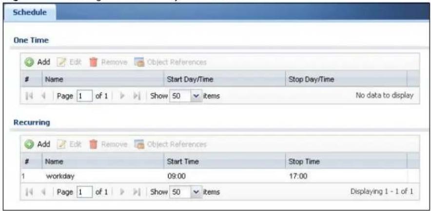
text_image
Schedule One Time Add Edit Remove Object ReferencesName Start Day/Time Stop Day/Time
Page 1 of 1 Show 50 items No data to display Recurring Add Edit Remove Object ReferencesName Start Time Stop Time
1 workday 09:00 17:00 Page 1 of 1 Show 50 items Displaying 1 - 1 of 1The following table describes the labels in this screen. See Section 36.2.1 on page 366 and Section 36.2.2 on page 367 for more information as well.
Table 168 Configuration > Object > Schedule
| LABEL DESCRIPTION | |
| One Time | |
| Add Click this to create a new entry. | |
| Edit | Double-click an entry or select it and click Edit to be able to modify the entry's settings. |
| Remove | To remove an entry, select it and click Remove. The UAG confirms you want to remove it before doing so. |
| Object Reference | Select an entry and click Object Reference to open a screen that shows which settings use the entry. See Section 10.3.2 on page 129 for an example. |
| # This field is a sequential value, and it is not associated with a specific schedule. | |
| Name | This field displays the name of the schedule, which is used to refer to the schedule. |
| Start Day / Time | This field displays the date and time at which the schedule begins. |
| Stop Day / Time | This field displays the date and time at which the schedule ends. |
| Recurring | |
| Add Click this to create a new entry. | |
| Edit | Double-click an entry or select it and click Edit to be able to modify the entry's settings. |
| Remove | To remove an entry, select it and click Remove. The UAG confirms you want to remove it before doing so. |
| Object Reference | Select an entry and click Object Reference to open a screen that shows which settings use the entry. See Section 10. 3. 2 on page 129 for an example. |
| # This field is a sequential value, and it is not associated with a specific schedule. | |
| Name | This field displays the name of the schedule, which is used to refer to the schedule. |
| Start Time This field displays the time at which the schedule begins. | |
| Stop Time This field displays the time at which the schedule ends. | |
36.2.1 The One-Time Schedule Add/Edit Screen
The One-Time Schedule Add/ Edit screen allows you to define a one-time schedule or edit an existing one. To access this screen, go to the Schedule screen (see Section 36.2 on page 365), and either click the Add icon or select an entry and click the Edit icon in the One Time section.
Figure 242 Configuration > Object > Schedule > Add/Edit (One Time)
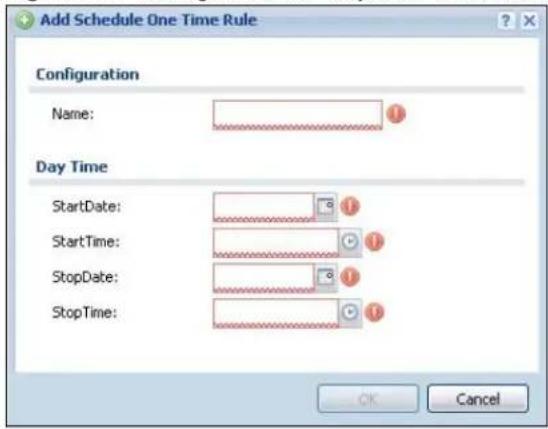
text_image
Add Schedule One Time Rule Configuration Name: Day Time StartDate: StartTime: StopDate: StopTime: OK CancelThe following table describes the labels in this screen.
Table 169 Configuration > Object > Schedule > Add/Edit (One Time)
| LABEL DESCRIPTION | |
| Configuration | |
| Name Type the | name used to refer to the one-time schedule. You may use 1-31 alphanumeric characters, underscores( ), or dashes (-), but the first character cannot be a number. This value is case-sensitive. |
| Date Time | |
| StartDate Specify the year, month, and day when the schedule begins.Year - 1900 - 2999Month - 1 - 12Day - 1 - 31 (it is not possible to specify illegal dates, such as February 31.) | |
| StartTime Specify the hour and minute when the schedule begins.Hour - 0 - 23Minute - 0 - 59 | |
| StopDate Specify the year, month, and day when the schedule ends.Year - 1900 - 2999Month - 1 - 12Day - 1 - 31 (it is not possible to specify illegal dates, such as February 31.) | |
| StopTime Specify the hour and minute when the schedule ends.Hour - 0 - 23Minute - 0 - 59 | |
| OK | Click OK to save your changes back to the UAG. |
| Cancel | Click Cancel to exit this screen without saving your changes. |
36.2.2 The Recurring Schedule Add/Edit Screen
The Recurring Schedule Add/ Edit screen allows you to define a recurring schedule or edit an existing one. To access this screen, go to the Schedule screen (see Section 36.2 on page 365), and click either the Add icon or an Edit icon in the Recurring section.
Figure 243 Configuration > Object > Schedule > Add/Edit (Recurring)
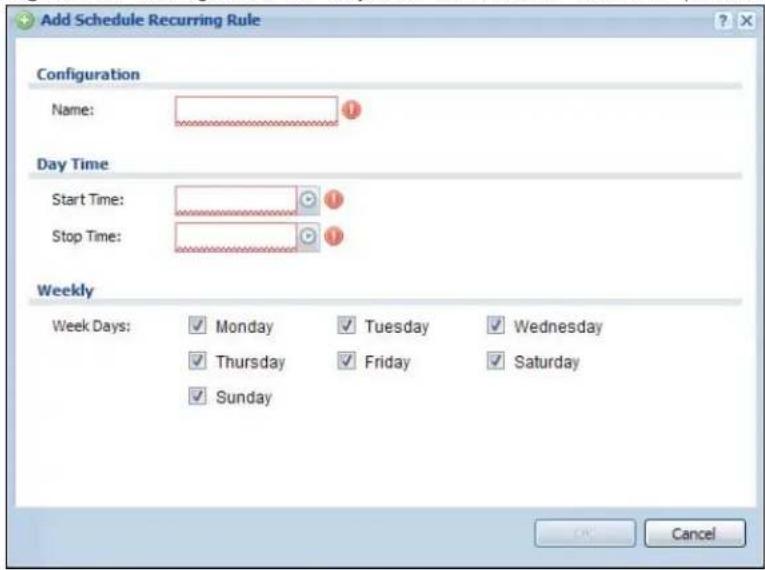
text_image
Add Schedule Recurring Rule Configuration Name: Day Time Start Time: Stop Time: Weekly Week Days: Monday Tuesday Wednesday Thursday Friday Saturday Sunday CancelThe Year, Month, and Day columns are not used in recurring schedules and are disabled in this screen. The following table describes the remaining labels in this screen.
Table 170 Configuration > Object > Schedule > Add/Edit (Recurring)
| LABEL DESCRIPTION | |
| Configuration | |
| Name | Type the name used to refer to the recurring schedule. You may use 1-31 alphanumeric characters, underscores( ), or dashes (-), but the first character cannot be a number. This value is case-sensitive. |
| Date Time | |
| StartTime Specify the hour and minute when the schedule begins each day.• Hour - 0 - 23• Minute - 0 - 59 | |
| StopTime Specify the hour and minute when the schedule ends each day.• Hour - 0 - 23• Minute - 0 - 59 | |
| Weekly | |
| Week Days | Select each day of the week the recurring schedule is effective. |
| OK | Click OK to save your changes back to the UAG. |
| Cancel | Click Cancel to exit this screen without saving your changes. |
AAA Server
37.1 Overview
You can use a AAA (Authentication, Authorization, Accounting) server to provide access control to your network. The AAA server can be a RADIUS server. Use the AAA Server screens to create and manage objects that contain settings for using AAA servers. You use AAA server objects in configuring ext-group-user user objects and authentication method objects (see Chapter 38 on page 372).
37.1.1 RADIUS Server
RADIUS (Remote Authentication Dial-In User Service) authentication is a popular protocol used to authenticate users by means of an external server instead of (or in addition to) an internal device user database that is limited to the memory capacity of the device. In essence, RADIUS authentication allows you to validate a large number of users from a central location.
Figure 244 RADIUS Server Network Example
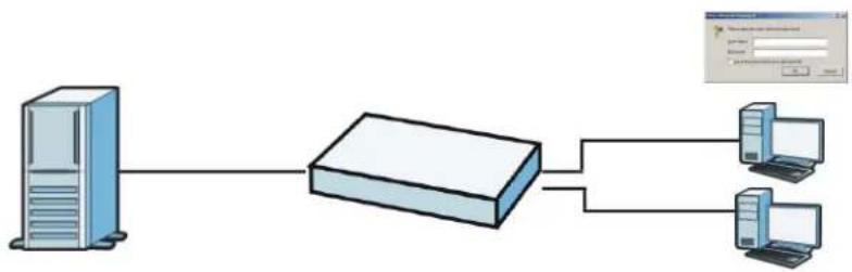
flowchart
graph LR
    A["Server"] --> B["Rout"]
    B --> C["Client Interface"]
    B --> D["Desktop Computer"]
    style A fill:#cce5ff,stroke:#333
    style B fill:#e6f7ff,stroke:#333
    style C fill:#e6f7ff,stroke:#333
    style D fill:#e6f7ff,stroke:#333
37.1.2 What You Can Do in this Chapter
Use the Configuration > Object > AAA Server > RADIUS screen (Section 37.2 on page 369) to configure the default external RADIUS server to use for user authentication.
37.1.3 What You Need To Know
AAA Servers Supported by the UAG
The following lists the types of authentication server the UAG supports.
- Local user database
The UAG uses the built-in local user database to authenticate administrative users logging into the UAG's Web Configurator or network access users logging into the network through the UAG.
• RADIUS
RADIUS (Remote Authentication Dial-In User Service) authentication is a popular protocol used to authenticate users by means of an external or built-in RADIUS server. RADIUS authentication allows you to validate a large number of users from a central location.
37.2 RADIUS Server Summary
Use the RADIUS screen to manage the list of RADIUS servers the UAG can use in authenticating users.
Click Configuration > Object > AAA Server > RADIUS to display the RADIUS screen.
Figure 245 Configuration > Object > AAA Server > RADIUS

text_image
RADIUS RADIUS Server Summary Add Edit Remove Object ReferenceName Server Address
1 radius Page 1 of 1 Show 50 items Displaying 1 - 1 of 1The following table describes the labels in this screen.
Table 171 Configuration > Object > AAA Server > RADIUS
| LABEL DESCRIPTION | |
| Add Click this to create a new entry. | |
| Edit | Double-click an entry or select it and click Edit to open a screen where you can modify the entry's settings. |
| Remove | To remove an entry, select it and click Remove. The UAG confirms you want to remove it before doing so. |
| Object Reference | Select an entry and click Object Reference to open a screen that shows which settings use the entry. See Section 10.3.2 on page 129 for an example. |
| # This field displays the index number. | |
| Name This is the name of the RADIUS server entry. | |
| Server Address This is the address of the RADIUS server. | |
37.2.1 Adding/Editing a RADIUS Server
Click Configuration > Object > AAA Server > RADIUS to display the RADIUS screen. Click the Add icon or select an entry and click the Edit icon to display the following screen. Use this screen to create a new RADIUS entry or edit an existing one.
Figure 246 Configuration > Object > AAA Server > RADIUS > Add/Edit

text_image
Add RADIUS General Settings Name: New Description: (Optional) Server Settings Server Address: IP or FQDN) Authentication Port: 1812 (1-65535) Backup Server Address: (IP or FQDN) (Optional) Backup Authentication Port: (1-65535) (Optional) Timeout: 5 (1-300 seconds) NAS IP Address: IP Address) ✓ Case-sensitive User Names Server Authentication Key: User Login Settings Group Membership Attribute: User Defined 26 (1-255) CancelThe following table describes the labels in this screen.
Table 172 Configuration > Object > AAA Server > RADIUS > Add/Edit
| LABEL DESCRIPTION | |
| Name | Enter a descriptive name (up to 63 alphanumerical characters) for identification purposes. |
| Description | Enter the description of each server, if any. You can use up to 60 printable ASCII characters. |
| Server Address Enter the address of the RADIUS server. | |
| Authentication Port | Specify the port number on the RADIUS server to which the UAG sends authentication requests. Enter a number between 1 and 65535. |
| Backup Server Address | If the RADIUS server has a backup server, enter its address here. |
| Backup Authentication Port | Specify the port number on the RADIUS server to which the UAG sends authentication requests. Enter a number between 1 and 65535. |
| Timeout | Specify the timeout period (between 1 and 300 seconds) before the UAG disconnects from the RADIUS server. In this case, user authentication fails.Search timeout occurs when either the user information is not in the RADIUS server or the RADIUS server is down. |
| NAS IP Address If | the RADIUS server requires the UAG to provide the Network Access Server (NAS) IP address attribute with a specific value, enter it here. |
| Case-sensitive User Names | Select this if the server checks the case of the usernames. |
| Key | Enter a password (up to 15 alphanumeric characters) as the key to be shared between the external authentication server and the UAG.The key is not sent over the network. This key must be the same on the external authentication server and the UAG. |
| Group Membership Attribute | A RADIUS server defines attributes for its accounts. Select the name and number of the attribute that the UAG is to check to determine to which group a user belongs. If it does not display, selectUser Definedandspecify the attribute’s number.This attribute’s value is called a group identifier; it determines to which group a user belongs. You can addext-group-useruser objects to identify groups based on these group identifier values.For example you could have an attribute named “memberOf” with values like “sales”, “RD”, and “management”. Then you could also create aext-group-useruser object for each group. One with “sales” as the group identifier, another for “RD” and a third for “management”. |
| OK Click OK to save the changes. | |
| Cancel | ClickCancelto discard the changes. |
Authentication Method
38.1 Overview
Authentication method objects set how the UAG authenticates wireless, HTTP/HTTPS clients, and peer IPSec routers (extended authentication) clients. Configure authentication method objects to have the UAG use the local user database, and/or the authentication servers and authentication server groups specified by AAA server objects. By default, user accounts created and stored on the UAG are authenticated locally.
38.1.1 What You Can Do in this Chapter
- Use the Configuration > Object > Auth. Method screens (Section 38.2 on page 372) to create and manage authentication method objects.
38.1.2 Before You Begin
Configure AAA server objects (see Chapter 37 on page 368) before you configure authentication method objects.
38.2 Authentication Method Objects
Click Configuration > Object > Auth. Method to display the screen as shown.
Note: You can create up to four authentication method objects.
Figure 247 Configuration > Object > Auth. Method
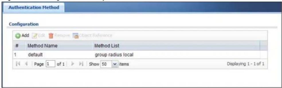
text_image
Authentication Method Configuration Add Edit Remove Object ReferenceMethod Name Method List
1 default group radius local Page 1 of 1 Show 50 items Displaying 1 - 1 of 1The following table describes the labels in this screen.
Table 173 Configuration > Object > Auth. Method
| LABEL DESCRIPTION | |
| Add Click this to | create a new entry. |
| Edit | Double-click an entry or select it and click Edit to open a screen where you can modify the entry's settings. |
| Remove | To remove an entry, select it and click Remove. The UAG confirms you want to remove it before doing so. |
| Object Reference | Select an entry and click Object Reference to open a screen that shows which settings use the entry. See Section 10.3.2 on page 129 for an example. |
| # This field displays the index number. | |
| Method Name This field displays a descriptive name for identification purposes. | |
| Method List This field displays the authentication method(s) for this entry. | |
38.2.1 Creating an Authentication Method Object
Follow the steps below to create an authentication method object.
1 Click Configuration > Object > Auth. Method.
2 Click Add.
3 Specify a descriptive name for identification purposes in the Name field. You may use 1-31 alphanumeric characters, underscores(_, or dashes (-), but the first character cannot be a number. This value is case-sensitive. For example, "My_Device".
4 Click Add to insert an authentication method in the table.
5 Select a server object from the Method List drop-down list box.
6 You can add up to four server objects to the table. The ordering of the Method List column is important. The UAG authenticates the users using the databases (in the local user database or the external authentication server) in the order they appear in this screen.
If two accounts with the same username exist on two authentication servers you specify, the UAG does not continue the search on the second authentication server when you enter the username and password that doesn't match the one on the first authentication server.
Note: You can NOT select two server objects of the same type.
7 Click OK to save the settings or click Cancel to discard all changes and return to the previous screen.
Figure 248 Configuration > Object > Auth. Method > Add
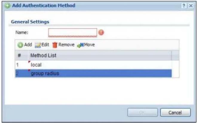
text_image
Add Authentication Method General Settings Name: Add Edit Remove MoveMethod List
1 local 2 group radius OK CancelThe following table describes the labels in this screen.
Table 174 Configuration > Object > Auth. Method > Add
| LABEL DESCRIPTION | |
| Name Specify a descriptive name for identification purposes. | |
| Add | Click this to create a new entry. Select an entry and click Add to create a new entry after the selected entry. |
| Edit | Double-click an entry or select it and click Edit to modify the entry's settings. |
| Remove | To remove an entry, select it and click Remove. The UAG confirms you want to remove it before doing so. |
| Move | To change a method's position in the numbered list, select the method and click Move to display a field to type a number for where you want to put it and press [ENTER] to move the rule to the number that you typed.The ordering of your methods is important as UAG authenticates the users using the authentication methods in the order they appear in this screen. |
| # This field displays the index number. | |
| Method List | Select a server object from the drop-down list box. You can create a server object in the AAA Server screen (see Chapter 37 on page 368 for more information).The UAG authenticates the users using the databases (in the local user database or the external authentication server) in the order they appear in this screen.If two accounts with the same username exist on two authentication servers you specify, the UAG does not continue the search on the second authentication server when you enter the username and password that doesn't match the one on the first authentication server. |
| OK Click OK to save the changes. | |
| Cancel | Click Cancel to discard the changes. |
39.1 Overview
The UAG can use certificates (also called digital IDs) to authenticate users. Certificates are based on public-private key pairs. A certificate contains the certificate owner's identity and public key. Certificates provide a way to exchange public keys for use in authentication.
39.1.1 What You Can Do in this Chapter
- Use the My Certificates screens (see Section 39.2 on page 378 to Section 39.2.3 on page 384) to generate and export self-signed certificates or certification requests and import the CA-signed certificates.
- Use the Trusted Certificates screens (see Section 39.3 on page 385 to Section 39.3.2 on page 389) to save CA certificates and trusted remote host certificates to the UAG. The UAG trusts any valid certificate that you have imported as a trusted certificate. It also trusts any valid certificate signed by any of the certificates that you have imported as a trusted certificate.
39.1.2 What You Need to Know
When using public-key cryptology for authentication, each host has two keys. One key is public and can be made openly available. The other key is private and must be kept secure.
These keys work like a handwritten signature (in fact, certificates are often referred to as "digital signatures"). Only you can write your signature exactly as it should look. When people know what your signature looks like, they can verify whether something was signed by you, or by someone else. In the same way, your private key "writes" your digital signature and your public key allows people to verify whether data was signed by you, or by someone else. This process works as follows.
1 Tim wants to send a message to Jenny. He needs her to be sure that it comes from him, and that the message content has not been altered by anyone else along the way. Tim generates a public key pair (one public key and one private key).
2 Tim keeps the private key and makes the public key openly available. This means that anyone who receives a message seeming to come from Tim can read it and verify whether it is really from him or not.
3 Tim uses his private key to sign the message and sends it to Jenny.
4 Jenny receives the message and uses Tim's public key to verify it. Jenny knows that the message is from Tim, and that although other people may have been able to read the message, no-one can have altered it (because they cannot re-sign the message with Tim's private key).
5 Additionally, Jenny uses her own private key to sign a message and Tim uses Jenny's public key to verify the message.
The UAG uses certificates based on public-key cryptology to authenticate users attempting to establish a connection, not to encrypt the data that you send after establishing a connection. The method used to secure the data that you send through an established connection depends on the type of connection.
The certification authority uses its private key to sign certificates. Anyone can then use the certification authority's public key to verify the certificates.
A certification path is the hierarchy of certification authority certificates that validate a certificate. The UAG does not trust a certificate if any certificate on its path has expired or been revoked.
Certification authorities maintain directory servers with databases of valid and revoked certificates. A directory of certificates that have been revoked before the scheduled expiration is called a CRL (Certificate Revocation List). The UAG can check a peer's certificate against a directory server's list of revoked certificates. The framework of servers, software, procedures and policies that handles keys is called PKI (public-key infrastructure).
Advantages of Certificates
Certificates offer the following benefits.
- The UAG only has to store the certificates of the certification authorities that you decide to trust, no matter how many devices you need to authenticate.
- Key distribution is simple and very secure since you can freely distribute public keys and you never need to transmit private keys.
Self-signed Certificates
You can have the UAG act as a certification authority and sign its own certificates.
Factory Default Certificate
The UAG generates its own unique self-signed certificate when you first turn it on. This certificate is referred to in the GUI as the factory default certificate.
Certificate File Formats
Any certificate that you want to import has to be in one of these file formats:
- Binary X.509: This is an ITU-T recommendation that defines the formats for X.509 certificates.
- PEM (Base-64) encoded X.509: This Privacy Enhanced Mail format uses lowercase letters, uppercase letters and numerals to convert a binary X.509 certificate into a printable form.
- Binary PKCS#7: This is a standard that defines the general syntax for data (including digital signatures) that may be encrypted. A PKCS #7 file is used to transfer a public key certificate. The private key is not included. The UAG currently allows the importation of a PKS#7 file that contains a single certificate.
- PEM (Base-64) encoded PKCS# 7: This Privacy Enhanced Mail (PEM) format uses lowercase letters, uppercase letters and numerals to convert a binary PKCS# 7 certificate into a printable form.
- Binary PKCS# 12: This is a format for transferring public key and private key certificates. The private key in a PKCS # 12 file is within a password-encrypted envelope. The file's password is not connected to your certificate's public or private passwords. Exporting a PKCS # 12 file creates this and you must provide it to decrypt the contents when you import the file into the UAG.
Note: Be careful not to convert a binary file to text during the transfer process. It is easy for this to occur since many programs use text files by default.
39.1.3 Verifying a Certificate
Before you import a trusted certificate into the UAG, you should verify that you have the correct certificate. You can do this using the certificate's fingerprint. A certificate's fingerprint is a message digest calculated using the MD5 or SHA1 algorithm. The following procedure describes how to check a certificate's fingerprint to verify that you have the actual certificate.
1 Browse to where you have the certificate saved on your computer.
2 Make sure that the certificate has a ".cer" or ".crt" file name extension.
Figure 249 Remote Host Certificates
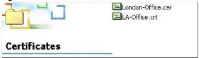
text_image
London-Office.cer LA-Office.crt Certificates3 Double-click the certificate's icon to open the Certificate window. Click the Details tab and scroll down to the Thumbprint Algorithm and Thumbprint fields.
Figure 250 Certificate Details

text_image
Certificate General Details Certification Path Show:4 Use a secure method to verify that the certificate owner has the same information in the Thumbprint Algorithm and Thumbprint fields. The secure method may very based on your situation. Possible examples would be over the telephone or through an HTTPS connection.
39.2 The My Certificates Screen
Click Configuration > Object > Certificate > My Certificates to open the My Certificates screen. This is the UAG's summary list of certificates and certification requests.
Figure 251 Configuration > Object > Certificate > My Certificates
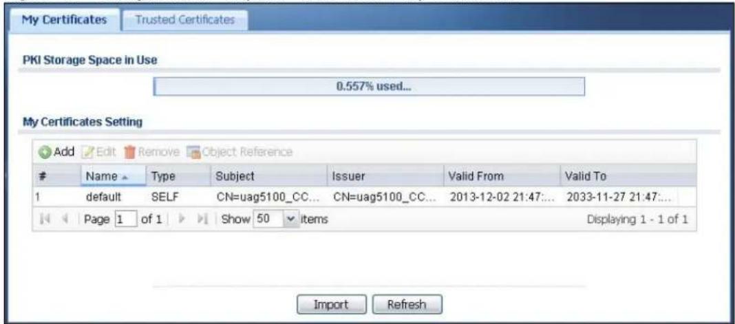
text_image
My Certificates Trusted Certificates PKI Storage Space in Use 0.557% used... My Certificates Setting Add Edit Remove Object ReferenceName Type Subject Issuer Valid From Valid To
1 default SELF CN=uag5100_CC... CN=uag5100_CC... 2013-12-02 21:47... 2033-11-27 21:47... Page 1 of 1 Show 50 items Displaying 1 - 1 of 1 Import RefreshThe following table describes the labels in this screen.
Table 175 Configuration > Object > Certificate > My Certificates
| LABEL DESCRIPTION | |
| PKI Storage Space in Use | This bar displays the percentage of the UAG's PKI storage space that is currently in use. When the storage space is almost full, you should consider deleting expired or unnecessary certificates before adding more certificates. |
| Add Click this to go | to the screen where you can have the UAG generate a certificate or a certification request. |
| Edit | Double-click an entry or select it and click Edit to open a screen with an in-depth list of information about the certificate. |
| Remove | The UAG keeps all of your certificates unless you specifically delete them. Uploading a new firmware or default configuration file does not delete your certificates. To remove an entry, select it and click Remove. The UAG confirms you want to remove it before doing so. Subsequent certificates move up by one when you take this action. |
| Object Reference | You cannot delete certificates that any of the UAG's features are configured to use. Select an entry and click Object Reference to open a screen that shows which settings use the entry. See Section 10.3.2 on page 129 for an example. |
| # This field displays the certificate index number. The certificates are listed in alphabetical order. | |
| Name | This field displays the name used to identify this certificate. It is recommended that you give each certificate a unique name. |
| Type This field displays what kind of certificate this is.REQ represents a certification request and is not yet a valid certificate. Send a certification request to a certification authority, which then issues a certificate. Use the My Certificate Import screen to import the certificate and replace the request.SELF represents a self-signed certificate.CERT represents a certificate issued by a certification authority. | |
| Subject | This field displays identifying information about the certificate's owner, such as CN (Common Name), OU (Organizational Unit or department), O (Organization or company) and C (Country). It is recommended that each certificate have unique subject information. |
| Issuer This field displays identifying information about the certificate's issuing certification authority, such as a common name, organizational unit or department, organization or company and country. With self-signed certificates, this is the same information as in the Subject field. | |
| Valid From | This field displays the date that the certificate becomes applicable. |
| Valid To | This field displays the date that the certificate expires. The text displays in red and includes an Expired! message if the certificate has expired. |
| Import | Click Import to open a screen where you can save a certificate to the UAG. |
| Refresh | Click Refresh to display the current validity status of the certificates. |
39.2.1 The My Certificates Add Screen
Click Configuration > Object > Certificate > My Certificates and then the Add icon to open the My Certificates Add screen. Use this screen to have the UAG create a self-signed certificate, enroll a certificate with a certification authority or generate a certification request.
Figure 252 Configuration > Object > Certificate > My Certificates > Add
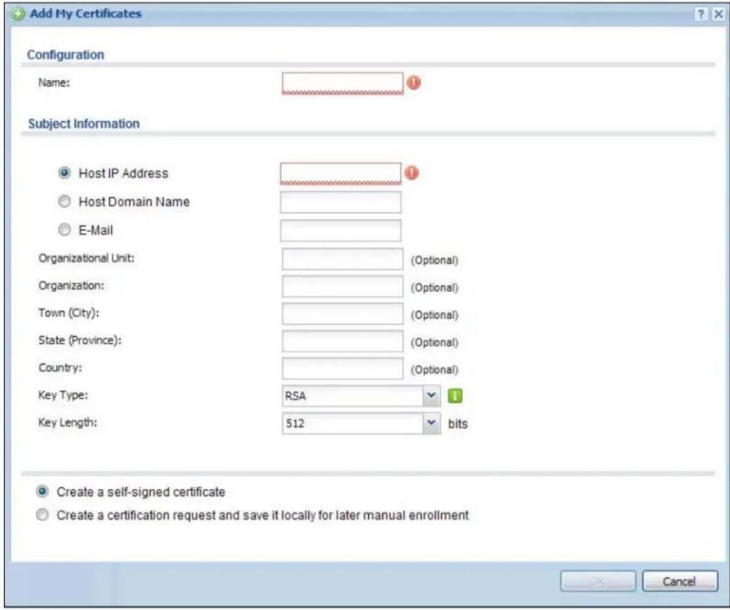
text_image
Add My Certificates Configuration Name: Subject Information Host IP Address Host Domain Name E-Mail Organizational Unit: (Optional) Organization: (Optional) Town (City): (Optional) State (Province): (Optional) Country: (Optional) Key Type: RSA 1 Key Length: 512 bits Create a self-signed certificate Create a certification request and save it locally for later manual enrollment CancelThe following table describes the labels in this screen.
Table 176 Configuration > Object > Certificate > My Certificates > Add
| LABEL DESCRIPTION | |
| Name Type a name to | identify this certificate. You can use up to 31 alphanumeric and ;~ !@# $%^ &() _+ [ ] { } ',= - characters. |
| Subject Information | Use these fields to record information that identifies the owner of the certificate. You do not have to fill in every field, although you must specify a Host IP Address, Host Domain Name, or E-Mail. The certification authority may add fields (such as a serial number) to the subject information when it issues a certificate. It is recommended that each certificate have unique subject information.Select a radio button to identify the certificate's owner by IP address, domain name or e-mail address. Type the IP address (in dotted decimal notation), domain name or e-mail address in the field provided. The domain name or e-mail address is for identification purposes only and can be any string.A domain name can be up to 255 characters. You can use alphanumeric characters, the hyphen and periods.An e-mail address can be up to 63 characters. You can use alphanumeric characters, the hyphen, the @ symbol, periods and the underscore. |
| Organizational Unit | Identify the organizational unit or department to which the certificate owner belongs. You can use up to 31 characters. You can use alphanumeric characters, the hyphen and the underscore. |
| Organization | Identify the company or group to which the certificate owner belongs. You can use up to 31 characters. You can use alphanumeric characters, the hyphen and the underscore. |
| Town (City) Identify the town or city where the certificate owner is located. You can use up to 31 characters. You can use alphanumeric characters, the hyphen and the underscore. | |
| State (Province) | Identify the state or province where the certificate owner is located. You can use up to 31 characters. You can use alphanumeric characters, the hyphen and the underscore. |
| Country Identify the nation where the certificate owner is located. You can use up to 31 characters. You can use alphanumeric characters, the hyphen and the underscore. | |
| Key Type | Select RSA to use the Rivest, Shamir and Adleman public-key algorithm.Select DSA to use the Digital Signature Algorithm public-key algorithm. |
| Key Length | Select a number from the drop-down list box to determine how many bits the key should use (512 to 2048). The longer the key, the more secure it is. A longer key also uses more PKI storage space. |
| Enrollment Options | These radio buttons deal with how and when the certificate is to be generated. |
| Create a self-signed certificate | Select this to have the UAG generate the certificate and act as the Certification Authority (CA) itself. This way you do not need to apply to a certification authority for certificates. |
| Create a certification request and save it locally for later manual enrollment | Select this to have the UAG generate and store a request for a certificate. Use the My Certificate Details screen to view the certification request and copy it to send to the certification authority.Copy the certification request from the My Certificate Details screen (see Section 39.2.2 on page 381) and then send it to the certification authority. |
| OK | Click OK to begin certificate or certification request generation. |
| Cancel | Click Cancel to quit and return to the My Certificates screen. |
39.2.2 The My Certificates Edit Screen
Click Configuration > Object > Certificate > My Certificates and then the Edit icon to open the My Certificate Edit screen. You can use this screen to view in-depth certificate information and change the certificate's name.
Figure 253 Configuration > Object > Certificate > My Certificates > Edit
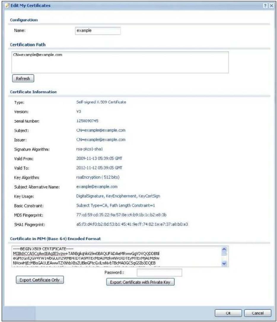
text_image
Edit My Certificates Configuration Name: example Certification Path CN=example@example.com Refresh Certificate Information Type: Self-signed X:509 Certificate Version: V3 Serial Number: 1258090745 Subject: CN=example@example.com Issuer: CN=example@example.com Signature Algorithm: rsa-pkcs1-sha1 Valid From: 2009-11-13 05:39:05 GMT Valid To: 2012-11-12 05:39:05 GMT Key Algorithm: rsaEncryption ( 512 bits) Subject Alternative Name: example@example.com Key Usage: DigitalSignature, KeyEncipherment, KeyCertSign Basic Constraint: Subject Type=CA, Path Length Constraint=1 MD5 Fingerprint: 77:cd:59:cd:35:22:9a:57:8e:c4:b9:1b:1c:b2:e8:3b SHA1 Fingerprint: a5:f3:d4:f0:b2:8d:53:b1:45:41:9e:ff:74:82:1e:e7:37:a0:b0:e3 Certificate in PEM (Base -64) Encoded Format ----BEGIN X509 CERTIFICATE---- MIIIdCCASCqAwIEAgIESvzw+TANBglqhklG9w0BAQUFADAeMRwwGgYDVQQDDBNI egFtCGxIQGY4YW1wbGLUYZ9MB4XDTA5MTExMzAIMzkWNVQXDTEyMTExMjAlMzkW NVowHjEcMBoGA1LEAwwTZXhhbXEsZUBeGFtcGxlmNvbTBcMAOGCSqGSlb3DQEB Password: Export Certificate Only Export Certificate with Private Key OK CancelThe following table describes the labels in this screen.
Table 177 Configuration > Object > Certificate > My Certificates > Edit
| LABEL DESCRIPTION | |
| Name | This field displays the identifying name of this certificate. You can use up to 31 alphanumeric and :‘~!@# $%^ &()_+[]{}',=- characters. |
| Certification Path | This field displays for a certificate, not a certification request.Click the Refresh button to have this read-only text box display the hierarchy of certification authorities that validate the certificate (and the certificate itself).If the issuing certification authority is one that you have imported as a trusted certification authority. it may be the only certification authority in the list (along with the certificate itself). If the certificate is a self-signed certificate, the certificate itself is the only one in the list. The UAG does not trust the certificate and displays “Not trusted” in this field if any certificate on the path has expired or been revoked. |
| Refresh Click Refresh | to display the certification path. |
| Certificate Information | These read-only fields display detailed information about the certificate. |
| Type This field displays general information about the certificate. CA-signed means that a Certification Authority signed the certificate. Self-signed means that the certificate's owner signed the certificate (not a certification authority). "X.509" means that this certificate was created and signed according to the ITU-T X.509 recommendation that defines the formats for public-key certificates. | |
| Version This field displays the X.509 version number. | |
| Serial Number | This field displays the certificate's identification number given by the certification authority or generated by the UAG. |
| Subject | This field displays information that identifies the owner of the certificate, such as Common Name (CN), Organizational Unit (OU), Organization (O), State (ST), and Country (C). |
| Issuer This field displays identifying information about the certificate's issuing certification authority, such as Common Name, Organizational Unit, Organization and Country. With self-signed certificates, this is the same as the Subject Name field. "none" displays for a certification request. | |
| Signature Algorithm | This field displays the type of algorithm that was used to sign the certificate. The UAG uses rsa-pkcs1-sha1 (RSA public-private key encryption algorithm and the SHA1 hash algorithm). Some certification authorities may use rsa-pkcs1-md5 (RSA public-private key encryption algorithm and the MD5 hash algorithm). |
| Valid From | This field displays the date that the certificate becomes applicable. "none" displays for a certification request. |
| Valid To | This field displays the date that the certificate expires. The text displays in red and includes an Expired! message if the certificate has expired. "none" displays for a certification request. |
| Key Algorithm | This field displays the type of algorithm that was used to generate the certificate's key pair (the UAG uses RSA encryption) and the length of the key set in bits (1024 bits for example). |
| Subject Alternative Name | This field displays the certificate owner's IP address (IP), domain name (DNS) or e-mail address (EMAIL). |
| Key Usage | This field displays for what functions the certificate's key can be used. For example, "DigitalSignature" means that the key can be used to sign certificates and "KeyEncipherment" means that the key can be used to encrypt text. |
| Basic Constraint | This field displays general information about the certificate. For example, Subject Type=CA means that this is a certification authority's certificate and "Path Length Constraint=1" means that there can only be one certification authority in the certificate's path. This field does not display for a certification request. |
| MD5 Fingerprint | This is the certificate's message digest that the UAG calculated using the MD5 algorithm. |
| SHA1 Fingerprint | This is the certificate's message digest that the UAG calculated using the SHA1 algorithm. |
| Certificate in PEM (Base-64) Encoded Format | This read-only text box displays the certificate or certification request in Privacy Enhanced Mail (PEM) format. PEM uses lowercase letters, uppercase letters and numerals to convert a binary certificate into a printable form.You can copy and paste a certification request into a certification authority's web page, an e-mail that you send to the certification authority or a text editor and save the file on a management computer for later manual enrollment.You can copy and paste a certificate into an e-mail to send to friends or colleagues or you can copy and paste a certificate into a text editor and save the file on a management computer for later distribution (via floppy disk for example). |
| Export Certificate Only | Use this button to save a copy of the certificate without its private key. Click this button and then Save in the File Download screen. The Save As screen opens, browse to the location that you want to use and click Save. |
| Password | If you want to export the certificate with its private key, create a password and type it here. Make sure you keep this password in a safe place. You will need to use it if you import the certificate to another device. |
| Export Certificate with Private Key | Use this button to save a copy of the certificate with its private key. Type the certificate's password and click this button. Click Save in the File Download screen. The Save As screen opens, browse to the location that you want to use and click Save. |
| OK | Click OK to save your changes back to the UAG. You can only change the name. |
| Cancel | Click Cancel to quit and return to the My Certificates screen. |
39.2.3 The My Certificates Import Screen
Click Configuration > Object > Certificate > My Certificates > Import to open the My Certificate Import screen. Follow the instructions in this screen to save an existing certificate to the UAG.
Note: You can import a certificate that matches a corresponding certification request that was generated by the UAG. You can also import a certificate in PKCS# 12 format, including the certificate's public and private keys.
The certificate you import replaces the corresponding request in the My Certificates screen.
You must remove any spaces from the certificate's filename before you can import it.
Figure 254 Configuration > Object > Certificate > My Certificates > Import
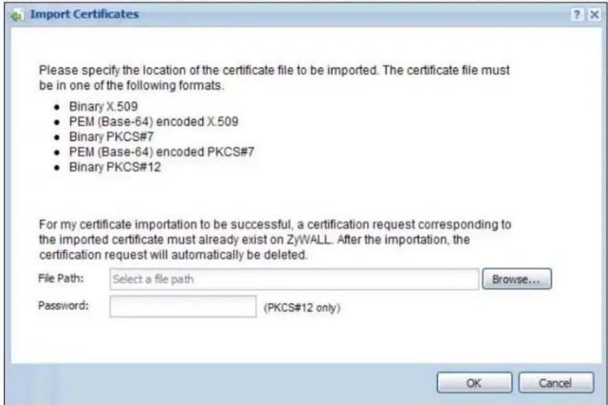
text_image
Import Certificates Please specify the location of the certificate file to be imported. The certificate file must be in one of the following formats. • Binary X.509 • PEM (Base-64) encoded X.509 • Binary PKCS#7 • PEM (Base-64) encoded PKCS#7 • Binary PKCS#12 For my certificate importation to be successful, a certification request corresponding to the imported certificate must already exist on ZyWALL. After the importation, the certification request will automatically be deleted. File Path: Select a file path Password: (PKCS#12 only) Browse... OK CancelThe following table describes the labels in this screen.
Table 178 Configuration > Object > Certificate > My Certificates > Import
| LABEL DESCRIPTION | |
| File Path | Type in the location of the file you want to upload in this field or clickBrowseto find it.You cannot import a certificate with the same name as a certificate that is already in the UAG. |
| Browse | ClickBrowseto find the certificate file you want to upload. |
| Password | This field only applies when you import a binary PKCS# 12 format file. Type the file's password that was created when the PKCS # 12 file was exported. |
| OK Click OK | to save the certificate on the UAG. |
| Cancel | ClickCancelto quit and return to theMy Certificatesscreen. |
39.3 The Trusted Certificates Screen
Click Configuration > Object > Certificate > Trusted Certificates to open the Trusted Certificates screen. This screen displays a summary list of certificates that you have set the UAG to accept as trusted. The UAG also accepts any valid certificate signed by a certificate on this list as being trustworthy; thus you do not need to import any certificate that is signed by one of these certificates.
Figure 255 Configuration > Object > Certificate > Trusted Certificates
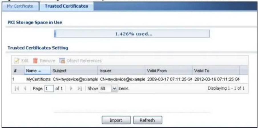
text_image
My Certificate Trusted Certificates PKI Storage Space in Use 1.426% used... Trusted Certificates Setting Edit Remove Object ReferencesName Subject Issuer Valid From Valid To
1 MyCertificate CN=mydevice@example CN=mydevice@example 2009-03-17 07:11:25 G#: 2012-03-16 07:11:25 G# Page 1 of 1 Show 50 items Displaying 1 - 1 of 1 Import RefreshThe following table describes the labels in this screen.
Table 179 Configuration > Object > Certificate > Trusted Certificates
| LABEL DESCRIPTION | |
| PKI Storage Space in Use | This bar displays the percentage of the UAG's PKI storage space that is currently in use. When the storage space is almost full, you should consider deleting expired or unnecessary certificates before adding more certificates. |
| Edit | Double-click an entry or select it and click Edit to open a screen with an in-depth list of information about the certificate. |
| Remove | The UAG keeps all of your certificates unless you specifically delete them. Uploading a new firmware or default configuration file does not delete your certificates. To remove an entry, select it and click Remove. The UAG confirms you want to remove it before doing so. Subsequent certificates move up by one when you take this action. |
| Object Reference | You cannot delete certificates that any of the UAG's features are configured to use. Select an entry and click Object Reference to open a screen that shows which settings use the entry. See Section 10.3.2 on page 129 for an example. |
| # This field displays the certificate index number. The certificates are listed in alphabetical order. | |
| Name This field displays the name used to identify this certificate. | |
| Subject | This field displays identifying information about the certificate's owner, such as CN (Common Name), OU (Organizational Unit or department), O (Organization or company) and C (Country). It is recommended that each certificate have unique subject information. |
| Issuer This field displays identifying information about the certificate's issuing certification authority, such as a common name, organizational unit or department, organization or company and country. With self-signed certificates, this is the same information as in the Subject field. | |
| Valid From This field displays the date that the certificate becomes applicable. | |
| Valid To | This field displays the date that the certificate expires. The text displays in red and includes an Expired! message if the certificate has expired. |
| Import | Click Import to open a screen where you can save the certificate of a certification authority that you trust, from your computer to the UAG. |
| Refresh | Click this button to display the current validity status of the certificates. |
39.3.1 The Trusted Certificates Edit Screen
Click Configuration > Object > Certificate > Trusted Certificates and then a certificate's Edit icon to open the Trusted Certificates Edit screen. Use this screen to view in-depth information about the certificate, change the certificate's name and set whether or not you want the UAG to check a certification authority's list of revoked certificates before trusting a certificate issued by the certification authority.
Figure 256 Configuration > Object > Certificate > Trusted Certificates > Edit
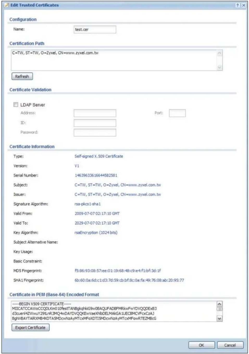
text_image
Edit Trusted Certificates Configuration Name: test.cer Certification Path C=TW, ST=TW, O=Zyxel, CN=www.zyxel.com.tw Refresh Certificate Validation LDAP Server Address: Port: ID: Password: Certificate Information Type: Self-signed X.509 Certificate Version: V1 Serial Number: 14639633616644582581 Subject: C=TW, ST=TW, O=Zyxel, CN=www.zyxel.com.tw Issuer: C=TW, ST=TW, O=Zyxel, CN=www.zyxel.com.tw Signature Algorithm: rsa-pkcs1-sha1 Valid From: 2009-07-07 02:17:10 GMT Valid To: 2029-07-07 02:17:10 GMT Key Algorithm: rsaEncryption (1024 bits) Subject Alternative Name: Key Usage: Basic Constraint: MD5 Fingerprint: f5:86:93:08:57:ee:01:19:68:48:c9:e4:f1:bf:3d:1f SHA1 Fingerprint: 6b:60:0a:6d:c1:d3:7d:59:cb:bf:8c:0a:fa:49:76:08:ab:20:95:77 Certificate in PEM (Base-64) Encoded Format ----BEGIN X509 CERTIFICATE---- MIICATCCAWoCCQDLKm010festTANBgkqhkiG9w0BAQUFADBFRkwFwYDVQQDExB3 d3cuenlHZWwuY29LnR3MQ4wDAYDVQQKEwVaeXhlbDELMAkGA1UECBMCVFcxCzAJ BgNVBAYTAIRXMB4xDTA5MDcwNzAyMTcxMFoXDTI5MDcwNzAyMTcxMFowRTEZMBcG Export Certificate OK CancelThe following table describes the labels in this screen.
Table 180 Configuration > Object > Certificate > Trusted Certificates > Edit
| LABEL DESCRIPTION | |
| Name This field displays the identifying name of this certificate. You can change the name. You can use up to 31 alphanumeric and ;‘~ !@# $%^ &()_+[]{} ’,= - characters. | |
| Certification Path | Click the Refresh button to have this read-only text box display the end entity's certificate and a list of certification authority certificates that shows the hierarchy of certification authorities that validate the end entity's certificate. If the issuing certification authority is one that you have imported as a trusted certificate, it may be the only certification authority in the list (along with the end entity's own certificate). The UAG does not trust the end entity's certificate and displays "Not trusted" in this field if any certificate on the path has expired or been revoked. |
| Refresh Click Refresh to display the certification path. | |
| LDAP Server | Select this check box if the directory server uses LDAP (Lightweight Directory Access Protocol). LDAP is a protocol over TCP that specifies how clients access directories of certificates and lists of revoked certificates. |
| Address Type the IP address (in dotted decimal notation) of the directory server. | |
| Port Use this field to specify the LDAP server port number. You must use the same server port number that the directory server uses. 389 is the default server port number for LDAP. | |
| ID The UAG may need to authenticate itself in order to assess the CRL directory server. Type the login name (up to 31 ASCII characters) from the entity maintaining the server (usually a certification authority). | |
| Password | Type the password (up to 31 ASCII characters) from the entity maintaining the CRL directory server (usually a certification authority). |
| Certificate Information | These read-only fields display detailed information about the certificate. |
| Type This field displays general information about the certificate. CA-signed means that a Certification Authority signed the certificate. Self-signed means that the certificate's owner signed the certificate (not a certification authority). X.509 means that this certificate was created and signed according to the ITU-T X.509 recommendation that defines the formats for public-key certificates. | |
| Version This field displays the X.509 version number. | |
| Serial Number | This field displays the certificate's identification number given by the certification authority. |
| Subject | This field displays information that identifies the owner of the certificate, such as Common Name (CN), Organizational Unit (OU), Organization (O) and Country (C). |
| Issuer | This field displays identifying information about the certificate's issuing certification authority, such as Common Name, Organizational Unit, Organization and Country. With self-signed certificates, this is the same information as in the Subject Name field. |
| Signature Algorithm | This field displays the type of algorithm that was used to sign the certificate. Some certification authorities use rsa-pkcs1-sha1 (RSA public-private key encryption algorithm and the SHA1 hash algorithm). Other certification authorities may use rsa-pkcs1-md5 (RSA public-private key encryption algorithm and the MD5 hash algorithm). |
| Valid From | This field displays the date that the certificate becomes applicable. The text displays in red and includes a Not Yet Valid! message if the certificate has not yet become applicable. |
| Valid To | This field displays the date that the certificate expires. The text displays in red and includes an Expiring! or Expired! message if the certificate is about to expire or has already expired. |
| Key Algorithm | This field displays the type of algorithm that was used to generate the certificate's key pair (the UAG uses RSA encryption) and the length of the key set in bits (1024 bits for example). |
| LABEL DESCRIPTION | |
| Subject Alternative Name | This field displays the certificate's owner's IP address (IP), domain name (DNS) or e-mail address (EMAIL). |
| Key Usage | This field displays for what functions the certificate's key can be used. For example, "DigitalSignature" means that the key can be used to sign certificates and "KeyEncipherment" means that the key can be used to encrypt text. |
| Basic Constraint | This field displays general information about the certificate. For example, Subject Type=CA means that this is a certification authority's certificate and "Path Length Constraint=1" means that there can only be one certification authority in the certificate's path. |
| MD5 Fingerprint This | is the certificate's message digest that the UAG calculated using the MD5 algorithm. You can use this value to verify with the certification authority (over the phone for example) that this is actually their certificate. |
| SHA1 Fingerprint This | is the certificate's message digest that the UAG calculated using the SHA1 algorithm. You can use this value to verify with the certification authority (over the phone for example) that this is actually their certificate. |
| Certificate in PEM(Base-64) Encoded Format | This read-only text box displays the certificate or certification request in Privacy Enhanced Mail (PEM) format. PEM uses lowercase letters, uppercase letters and numerals to convert a binary certificate into a printable form.You can copy and paste the certificate into an e-mail to send to friends or colleagues or you can copy and paste the certificate into a text editor and save the file on a management computer for later distribution (via floppy disk for example). |
| Export Certificate | Click this button and then Save in the File Download screen. The Save As screen opens, browse to the location that you want to use and click Save. |
| OK | Click OK to save your changes back to the UAG. You can only change the name. |
| Cancel | Click Cancel to quit and return to the Trusted Certificates screen. |
39.3.2 The Trusted Certificates Import Screen
Click Configuration > Object > Certificate > Trusted Certificates > Import to open the Trusted Certificates Import screen. Follow the instructions in this screen to save a trusted certificate to the UAG.
Note: You must remove any spaces from the certificate's filename before you can import the certificate.
Figure 257 Configuration > Object > Certificate > Trusted Certificates > Import
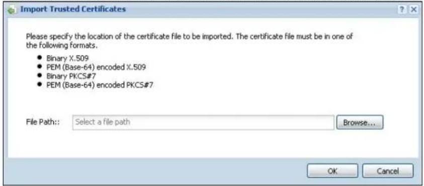
text_image
Import Trusted Certificates Please specify the location of the certificate file to be imported. The certificate file must be in one of the following formats. • Binary X.509 • PEM (Base-64) encoded X.509 • Binary PKCS#7 • PEM (Base-64) encoded PKCS#7 File Path: Select a file path Browse... OK CancelThe following table describes the labels in this screen.
Table 181 Configuration > Object > Certificate > Trusted Certificates > Import
| LABEL DESCRIPTION | |
| File Path | Type in the location of the file you want to upload in this field or clickBrowseto find it.You cannot import a certificate with the same name as a certificate that is already in the UAG. |
| Browse | ClickBrowseto find the certificate file you want to upload. |
| OK Click OK to save the certificate on the UAG. | |
| Cancel | ClickCancelto quit and return to the previous screen. |
40.1 Overview
Use ISP accounts to manage Internet Service Provider (ISP) account information for PPPoE/PPTP interfaces. An ISP account is a profile of settings for Internet access using PPPoE or PPTP.
Finding Out More
• See Section 10.4 on page 132 for information about PPPoE/PPTP interfaces.
40.1.1 What You Can Do in this Chapter
Use the Object > ISP Account screens (Section 40.2 on page 391) to create and manage ISP accounts in the UAG.
40.2 ISP Account Summary
This screen provides a summary of ISP accounts in the UAG. To access this screen, click Configuration > Object > ISP Account.
Figure 258 Configuration > Object > ISP Account
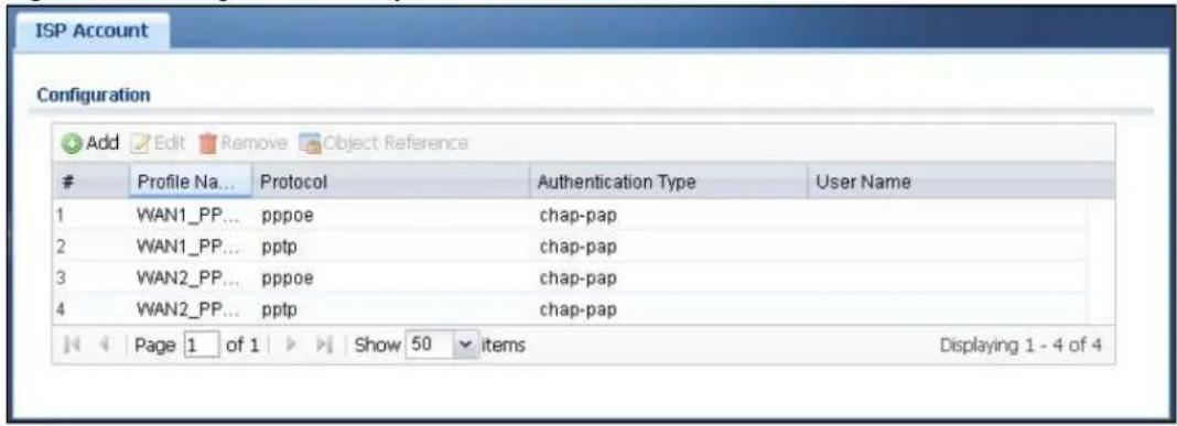
text_image
ISP Account ConfigurationProfile Na... Protocol Authentication Type User Name
1 WAN1_PP... pppoe chap-pap 2 WAN1_PP... pptp chap-pap 3 WAN2_PP... pppoe chap-pap 4 WAN2_PP... pptp chap-pap Page 1 of 1 Show 50 items Displaying 1 - 4 of 4The following table describes the labels in this screen. See the ISP Account Add/Edit section below for more information as well.
Table 182 Configuration > Object > ISP Account
| LABEL DESCRIPTION | |
| Add Click this to create a new entry. | |
| Edit | Double-click an entry or select it and click Edit to be able to modify the entry's settings. |
| Remove | To remove an entry, select it and click Remove. The UAG confirms you want to remove it before doing so. |
| Object Reference | Select an entry and click Object Reference to open a screen that shows which settings use the entry. See Section 10.3.2 on page 129 for an example. |
| # This field is a sequential value, and it is not associated with a specific entry. | |
| Profile Name | This field displays the profile name of the ISP account. This name is used to identify the ISP account. |
| Protocol This field | displays the protocol used by the ISP account. |
| Authentication Type | This field displays the authentication type used by the ISP account. |
| User Name This field displays the user name of the ISP account. | |
40.2.1 ISP Account Add/Edit
The ISP Account Edit screen lets you add information about new accounts and edit information about existing accounts. To open this window, open the ISP Account screen. (See Section 40.2 on page 391.) Then, click the Add icon or select an entry and click the Edit icon to open the ISP Account Edit screen below.
Figure 259 Configuration > Object > ISP Account > Add/Edit
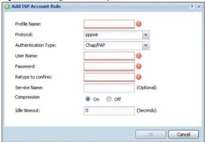
text_image
Add ISP Account Rule Profile Name: Protocol: pppoe Authentication Type: Chap/PAP User Name: Password: Retype to confirm: Service Name: (Optional) Compression On Off Idle timeout: 0 (Seconds) OK CancelThe following table describes the labels in this screen.
Table 183 Configuration > Object > ISP Account > Add/Edit
| LABEL DESCRIPTION | |
| Profile Name | This field is read-only if you are editing an existing account. Type in the profile name of the ISP account. The profile name is used to refer to the ISP account. You may use 1-31 alphanumeric characters, underscores( ), or dashes (-), but the first character cannot be a number. This value is case-sensitive. |
| Protocol | This field is read-only if you are editing an existing account. Select the protocol used by the ISP account. Options are:pppoe - This ISP account uses the PPPoE protocol.pptp - This ISP account uses the PPTP protocol. |
| Authentication Type | Use the drop-down list box to select an authentication protocol for outgoing calls. Options are:CHAP/ PAP- Your UAG accepts either CHAP or PAP when requested by this remote node.Chap- Your UAG accepts CHAP only.PAP- Your UAG accepts PAP only.MSCHAP- Your UAG accepts MSCHAP only.MSCHAP-V2- Your UAG accepts MSCHAP-V2 only. |
| Encryption Method | This field is available if this ISP account uses the PPTP protocol. Use the drop-down list box to select the type of Microsoft Point-to-Point Encryption (MPPE). Options are:nomppe- This ISP account does not use MPPE.mppe-40- This ISP account uses 40-bit MPPE.mppe-128- This ISP account uses 128-bit MMPE. |
| User Name Type the user name given to you by your ISP. | |
| Password | Type the password associated with the user name above. The password can only consist of alphanumeric characters (A-Z, a-z, 0-9). This field can be blank. |
| Retype to Confirm | Type your password again to make sure that you have entered is correctly. |
| Server IP | If this ISP account uses the PPPoE protocol, this field is not displayed.If this ISP account uses the PPTP protocol, type the IP address of the PPTP server. |
| Connection ID | This field is available if this ISP account uses the PPTP protocol. Type your identification name for the PPTP server. This field can be blank. |
| Service Name If this | Is ISP account uses the PPPoE protocol, type the PPPoE service name to access. PPPoE uses the specified service name to identify and reach the PPPoE server. This field can be blank.If this ISP account uses the PPTP protocol, this field is not displayed. |
| Compression | Select On button to turn on stac compression, and select Off to turn off stac compression. Stac compression is a data compression technique capable of compressing data by a factor of about four. |
| Idle Timeout This value specifies the number of seconds that must elapse without outbound traffic before the UAG automatically disconnects from the PPPoE/PPTP server. This value must be an integer between 0 and 360. If this value is zero, this timeout is disabled. | |
| OK | Click OK to save your changes back to the UAG. If there are no errors, the program returns to the ISP Account screen. If there are errors, a message box explains the error, and the program stays in the ISP Account Edit screen. |
| Cancel | Click Cancel to return to the ISP Account screen without creating the profile (if it is new) or saving any changes to the profile (if it already exists). |
41.1 Overview
Use the system screens to configure general UAG settings.
41.1.1 What You Can Do in this Chapter
- Use the System > Host Name screen (see Section 41.2 on page 395) to configure a unique name for the UAG in your network.
- Use the System > USB Storage screen (see Section 41.3 on page 395) to configure the settings for the connected USB devices.
- Use the System > Date/ Time screen (see Section 41.4 on page 396) to configure the date and time for the UAG.
- Use the System > Console Speed screen (see Section 41.5 on page 400) to configure the console port speed when you connect to the UAG via the console port using a terminal emulation program.
- Use the System > DNS screen (see Section 41.6 on page 401) to configure the DNS (Domain Name System) server used for mapping a domain name to its corresponding IP address and vice versa.
- Use the System > WWW screens (see Section 41.7 on page 407) to configure settings for HTTP or HTTPS access to the UAG and how the login and access user screens look.
- Use the System > SSH screen (see Section 41.8 on page 423) to configure SSH (Secure SHell) used to securely access the UAG's command line interface. You can specify which zones allow SSH access and from which IP address the access can come.
- Use the System > TELNET screen (see Section 41.9 on page 428) to configure Telnet to access the UAG's command line interface. Specify which zones allow Telnet access and from which IP address the access can come.
- Use the System > FTP screen (see Section 41.10 on page 429) to specify from which zones FTP can be used to access the UAG. You can also specify from which IP addresses the access can come. You can upload and download the UAG's firmware and configuration files using FTP. Please also see Chapter 43 on page 450 for more information about firmware and configuration files.
- Your UAG can act as an SNMP agent, which allows a manager station to manage and monitor the UAG through the network. Use the System > SNMP screen (see Section 41.11 on page 430) to configure SNMP settings, including from which zones SNMP can be used to access the UAG. You can also specify from which IP addresses the access can come.
- The Language screen (Section 41.12 on page 434) sets the user interface language for the UAG's Web Configurator screens.
Note: See each section for related background information and term definitions.
41.2 Host Name
A host name is the unique name by which a device is known on a network. Click Configuration > System > Host Name to open the Host Name screen.
Figure 260 Configuration > System > Host Name
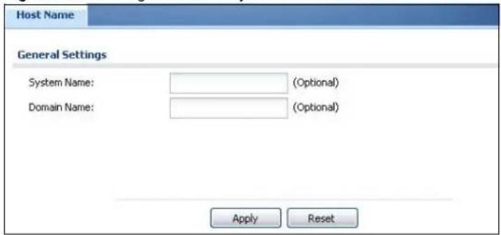
text_image
Host Name General Settings System Name: (Optional) Domain Name: (Optional) Apply ResetThe following table describes the labels in this screen.
Table 184 Configuration > System > Host Name
| LABEL DESCRIPTION | |
| System Name | Enter a descriptive name to identify your UAG device. This name can be up to 64 alphanumeric characters long. Spaces are not allowed, but dashes (-) underscores (_ ) and periods (.) are accepted. |
| Domain Name | Enter the domain name (if you know it) here. This name is propagated to DHCP clients connected to interfaces with the DHCP server enabled. This name can be up to 254 alphanumeric characters long. Spaces are not allowed, but dashes “-” are accepted. |
| Apply | Click Apply to save your changes back to the UAG. |
| Reset | Click Reset to return the screen to its last-saved settings. |
41.3 USB Storage
The UAG can use a connected USB device to store the system log and other diagnostic information. Use this screen to turn on this feature and set a disk full warning limit.
Note: Only connect one USB device. It must allow writing (it cannot be read-only) and use the FAT16, FAT32, EXT2, or EXT3 file system.
Click Configuration > System > USB Storage to open the screen as shown next.
Figure 261 Configuration > System > USB Storage
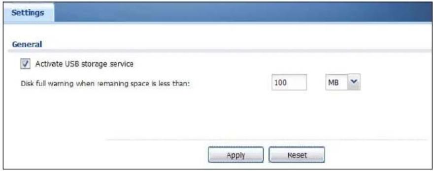
text_image
Settings General ✓ Activate USB storage service Disk full warning when remaining space is less than: 100 MB Apply ResetThe following table describes the labels in this screen.
Table 185 Configuration > System > USB Storage
| LABEL DESCRIPTION | |
| Activate USB storage service | Select this if you want to use the connected USB device(s). |
| Disk full warning when remaining space is less than | Set a number and select a unit (MB or %) to have the UAG send a warning message when the remaining USB storage space is less than the value you set here. |
| Apply | Click Apply to save your changes back to the UAG. |
| Reset | Click Reset to return the screen to its last-saved settings. |
41.4 Date and Time
For effective scheduling and logging, the UAG system time must be accurate. The UAG's Real Time Chip (RTC) keeps track of the time and date. There is also a software mechanism to set the time manually or get the current time and date from an external server.
To change your UAG's time based on your local time zone and date, click Configuration > System > Date/ Time. The screen displays as shown. You can manually set the UAG's time and date or have the UAG get the date and time from a time server.
Figure 262 Configuration > System > Date and Time
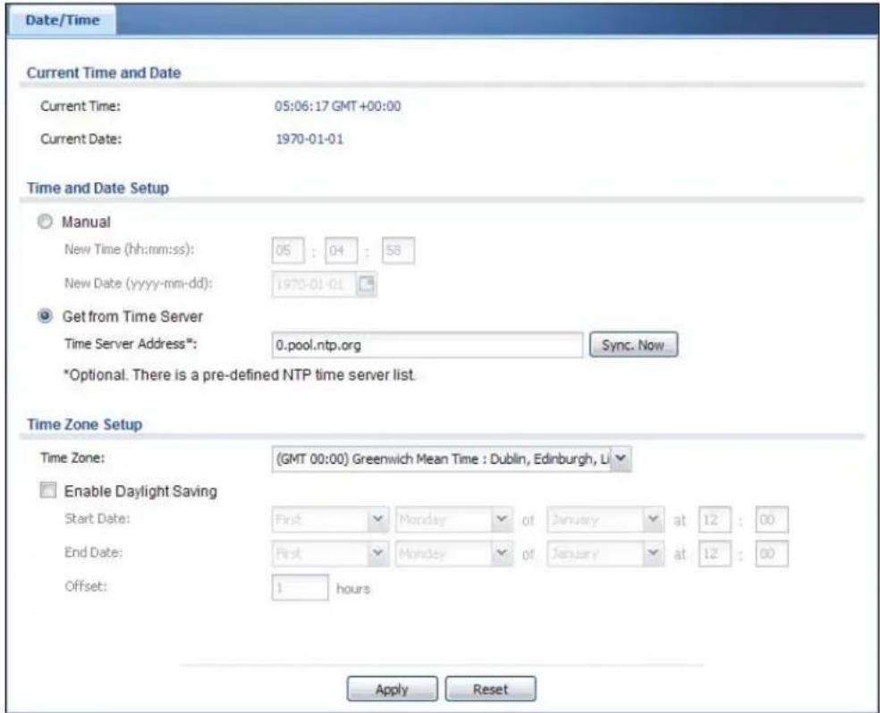
text_image
Date/Time Current Time and Date Current Time: 05:06:17 GMT +00:00 Current Date: 1970-01-01 Time and Date Setup Manual New Time (hh:mm:ss): 05 : 04 : 58 New Date (yyyy-mm-dd): 1970-01-01 Get from Time Server Time Server Address*: 0.pool.ntp.org Sync. Now *Optional. There is a pre-defined NTP time server list. Time Zone Setup Time Zone: (GMT 00:00) Greenwich Mean Time : Dublin, Edinburgh, L Enable Daylight Saving Start Date: First Monday of January at 12 : 00 End Date: First Monday of January at 12 : 00 Offset: 1 hours Apply ResetThe following table describes the labels in this screen.
Table 186 Configuration > System > Date and Time
| LABEL DESCRIPTION | |
| Current Time and Date | |
| Current Time This field displays the present time of your UAG. | |
| Current Date This field displays the present date of your UAG. | |
| Time and Date Setup | |
| Manual | Select this radio button to enter the time and date manually. If you configure a new time and date, time zone and daylight saving at the same time, the time zone and daylight saving will affect the new time and date you entered. When you enter the time settings manually, the UAG uses the new setting once you click Apply. |
| New Time (hh-mm-ss) | This field displays the last updated time from the time server or the last time configured manually.When you set Time and Date Setup to Manual, enter the new time in this field and then click Apply. |
| New Date (yyyy-mm-dd) | This field displays the last updated date from the time server or the last date configured manually.When you set Time and Date Setup to Manual, enter the new date in this field and then click Apply. |
| LABEL DESCRIPTION | |
| Get from Time Server | Select this radio button to have the UAG get the time and date from the time server you specify below. The UAG requests time and date settings from the time server under the following circumstances.When the UAG starts up.When you clickApplyorSync.Nowin this screen.24-hour intervals after starting up. |
| Time Server Address | Enter the IP address or URL of your time server. Check with your ISP/network administrator if you are unsure of this information. |
| Sync. Now | Click this button to have the UAG get the time and date from a time server (see the Time Server Address field). This also saves your changes (except the daylight saving settings). |
| Time Zone Setup | |
| Time Zone | Choose the time zone of your location. This will set the time difference between your time zone and Greenwich Mean Time (GMT). |
| Enable Daylight Savings | Daylight saving is a period from late spring to early fall when many countries set their clocks ahead of normal local time by one hour to give more daytime light in the evening.Select this option if you use Daylight Saving Time. |
| Start Date | Configure the day and time when Daylight Saving Time starts if you selectedEnable Daylight Savings. Theatfield uses the 24 hour format. Here are a couple of examples:Daylight Saving Time starts in most parts of the United States on the second Sunday of March. Each time zone in the United States starts using Daylight Saving Time at 2 A.M. local time. So in the United States you would selectSecond, Sunday, Marchand type 2 in theatfield.Daylight Saving Time starts in the European Union on the last Sunday of March. All of the time zones in the European Union start using Daylight Saving Time at the same moment (1 A.M. GMT or UTC). So in the European Union you would selectLast,Sunday, March. The time you type in theatfield depends on your time zone. In Germany for instance, you would type 2 because Germany's time zone is one hour ahead of GMT or UTC (GMT+1). |
| End Date | Configure the day and time when Daylight Saving Time ends if you selectedEnable Daylight Savings. Theatfield uses the 24 hour format. Here are a couple of examples:Daylight Saving Time ends in the United States on the first Sunday of November. Each time zone in the United States stops using Daylight Saving Time at 2 A.M. local time. So in the United States you would selectFirst, Sunday, Novemberand type 2 in theatfield.Daylight Saving Time ends in the European Union on the last Sunday of October. All of the time zones in the European Union stop using Daylight Saving Time at the same moment (1 A.M. GMT or UTC). So in the European Union you would selectLast,Sunday, October. The time you type in theatfield depends on your time zone. In Germany for instance, you would type 2 because Germany's time zone is one hour ahead of GMT or UTC (GMT+1). |
| Offset | Specify how much the clock changes when daylight saving begins and ends.Enter a number from 1 to 5.5 (by 0.5 increments).For example, if you set this field to 3.5, a log occurred at 6 P.M. in local official time will appear as if it had occurred at 10:30 P.M. |
| Apply | ClickApplyto save your changes back to the UAG. |
| Reset | ClickResetto return the screen to its last-saved settings. |
41.4.1 Pre-defined NTP Time Servers List
When you turn on the UAG for the first time, the date and time start at 2003-01-01 00:00:00. The UAG then attempts to synchronize with one of the following pre-defined list of Network Time Protocol (NTP) time servers.
The UAG continues to use the following pre-defined list of NTP time servers if you do not specify a time server or it cannot synchronize with the time server you specified.
Table 187 Default Time Servers
| 0.pool.ntp.org |
| 1.pool.ntp.org |
| 2.pool.ntp.org |
When the UAG uses the pre-defined list of NTP time servers, it randomly selects one server and tries to synchronize with it. If the synchronization fails, then the UAG goes through the rest of the list in order from the first one tried until either it is successful or all the pre-defined NTP time servers have been tried.
41.4.2 Time Server Synchronization
Click the Synchronize Now button to get the time and date from the time server you specified in the Time Server Address field.
When the Loading... screen appears, you may have to wait up to one minute.
Figure 263 Synchronization in Process

The Current Time and Current Date fields will display the appropriate settings if the synchronization is successful.
If the synchronization was not successful, a log displays in the View Log screen. Try re-configuring the Date/Time screen.
To manually set the UAG date and time.
1 Click System > Date/ Time.
2 Select Manual under Time and Date Setup.
3 Enter the UAG's time in the New Time field.
4 Enter the UAG's date in the New Date field.
5 Under Time Zone Setup, select your Time Zone from the list.
6 As an option you can select the Enable Daylight Saving check box to adjust the UAG clock for daylight savings.
7 Click Apply.
To get the UAG date and time from a time server
1 Click System > Date/ Time.
2 Select Get from Time Server under Time and Date Setup.
3 Under Time Zone Setup, select your Time Zone from the list.
4 As an option you can select the Enable Daylight Saving check box to adjust the UAG clock for daylight savings.
5 Under Time and Date Setup, enter a Time Server Address (Table 187 on page 399).
6 Click Apply.
41.5 Console Port Speed
This section shows you how to set the console port speed when you connect to the UAG via the console port using a terminal emulation program. See Table 1 on page 20 for default console port settings.
Click Configuration > System > Console Speed to open the Console Speed screen.
Figure 264 Configuration > System > Console Speed

text_image
Console Speed General Settings Console Port Speed: 115200 Apply ResetThe following table describes the labels in this screen.
Table 188 Configuration > System > Console Speed
| LABEL DESCRIPTION | |
| Console Port Speed | Use the drop-down list box to change the speed of the console port. Your UAG supports 9600, 19200, 38400, 57600, and 115200 bps (default) for the console port.The Console Port Speed applies to a console port connection using terminal emulation software and NOT the Console in the UAG Web Configurator Status screen. |
| Apply | Click Apply to save your changes back to the UAG. |
| Reset | Click Reset to return the screen to its last-saved settings. |
41.6 DNS Overview
DNS (Domain Name System) is for mapping a domain name to its corresponding IP address and vice versa. The DNS server is extremely important because without it, you must know the IP address of a machine before you can access it.
41.6.1 DNS Server Address Assignment
The UAG can get the DNS server addresses in the following ways.
- The ISP tells you the DNS server addresses, usually in the form of an information sheet, when you sign up. If your ISP gives you DNS server addresses, manually enter them in the DNS server fields.
- If your ISP dynamically assigns the DNS server IP addresses (along with the UAG's WAN IP address), set the DNS server fields to get the DNS server address from the ISP.
- You can manually enter the IP addresses of other DNS servers.
41.6.2 Configuring the DNS Screen
Click Configuration > System > DNS to change your UAG's DNS settings. Use the DNS screen to configure the UAG to use a DNS server to resolve domain names for UAG system features like VPN, DDNS and the time server. You can also configure the UAG to accept or discard DNS queries. Use the Network > Interface screens to configure the DNS server information that the UAG sends to the specified DHCP client devices.
Figure 265 Configuration > System > DNS

text_image
DNS Address/PTR Record Add Edit RemoveFQDN IP Address
Page 1 of 1 Show 50 items No data to display Domain Zone Forwarder Add Edit Remove MoveDomain Zone Type DNS Server Query via
Default 10.5.5.1 wan2 Page 1 of 1 Show 50 items Displaying 1 - 1 of 1 MX Record (for My FQDN) Add Edit RemoveDomain Name IP/FQDN
Page 1 of 1 Show 50 items No data to display Service Control Add Edit Remove MoveZone Address Action
ALL ALL Accept Page 1 of 1 Show 50 items Displaying 1 - 1 of 1The following table describes the labels in this screen.
Table 189 Configuration > System > DNS
| LABEL DESCRIPTION | |
| Address/PTR Record | This record specifies the mapping of a Fully-Qualified Domain Name (FQDN) to an IP address. An FQDN consists of a host and domain name. For example, www.zyxel.com.tw is a fully qualified domain name, where "www" is the host, "zyxel" is the third-level domain, "com" is the second-level domain, and "tw" is the top level domain. |
| Add Click this to create a new entry. | |
| Edit | Double-click an entry or select it and click Edit to be able to modify the entry's settings. |
| Remove | To remove an entry, select it and click Remove. The UAG confirms you want to remove it before doing so. Note that subsequent entries move up by one when you take this action. |
| # This is the index number of the address/PTR record. | |
| FQDN This is a host's fully qualified domain name. | |
| IP Address This is the IP address of a host. | |
| Domain Zone Forwarder | This specifies a DNS server's IP address. The UAG can query the DNS server to resolve domain zones for features like VPN, DDNS and the time server.When the UAG needs to resolve a domain zone, it checks it against the domain zone forwarder entries in the order that they appear in this list. |
| Add | Click this to create a new entry. Select an entry and click Add to create a new entry after the selected entry. |
| Edit | Double-click an entry or select it and click Edit to be able to modify the entry's settings. |
| Remove | To remove an entry, select it and click Remove. The UAG confirms you want to remove it before doing so. Note that subsequent entries move up by one when you take this action. |
| Move | To change an entry's position in the numbered list, select the method and click Move to display a field to type a number for where you want to put it and press [ENTER] to move the rule to the number that you typed. |
| # | This is the index number of the domain zone forwarder record. The ordering of your rules is important as rules are applied in sequence.A hyphen (-) displays for the default domain zone forwarder record. The default record is not configurable. The UAG uses this default record if the domain zone that needs to be resolved does not match any of the other domain zone forwarder records. |
| Domain Zone | A domain zone is a fully qualified domain name without the host. For example, zyxel.com.tw is the domain zone for the www.zyxel.com.tw fully qualified domain name.A “*” means all domain zones. |
| Type | This displays whether the DNS server IP address is assigned by the ISP dynamically through a specified interface or configured manually (User-Defined). |
| DNS Server | This is the IP address of a DNS server. This field displays N/A if you have the UAG get a DNS server IP address from the ISP dynamically but the specified interface is not active. |
| Query Via | This is the interface through which the UAG sends DNS queries to the entry's DNS server. If the UAG connects through a VPN tunnel, tunnel displays. |
| MX Record (for My FQDN) | A MX (Mail eXchange) record identifies a mail server that handles the mail for a particular domain. |
| Add Click this to create a new entry. | |
| Edit | Double-click an entry or select it and click Edit to be able to modify the entry's settings. |
| Remove | To remove an entry, select it and click Remove. The UAG confirms you want to remove it before doing so. Note that subsequent entries move up by one when you take this action. |
| # This is the index number of the MX record. | |
| Domain Name | This is the domain name where the mail is destined for. |
| IP/FQDN | This is the IP address or Fully-Qualified Domain Name (FQDN) of a mail server that handles the mail for the domain specified in the field above. |
| Service Control | This specifies from which computers and zones you can send DNS queries to the UAG. |
| Add | Click this to create a new entry. Select an entry and click Add to create a new entry after the selected entry. |
| Edit | Double-click an entry or select it and click Edit to be able to modify the entry's settings. |
| Remove | To remove an entry, select it and click Remove. The UAG confirms you want to remove it before doing so. Note that subsequent entries move up by one when you take this action. |
| Move | To change an entry's position in the numbered list, select the method and click Move to display a field to type a number for where you want to put it and press [ENTER] to move the rule to the number that you typed. |
| # | This the index number of the service control rule. The ordering of your rules is important as rules are applied in sequence.The entry with a hyphen (-) instead of a number is the UAG's (non-configurable) default policy. The UAG applies this to traffic that does not match any other configured rule. It is not an editable rule. To apply other behavior, configure a rule that traffic will match so the UAG will not have to use the default policy. |
| Zone | This is the zone on the UAG the user is allowed or denied to access. |
| Address | This is the object name of the IP address(es) with which the computer is allowed or denied to send DNS queries. |
| Action This displays | whether the UAG accepts DNS queries from the computer with the IP address specified above through the specified zone (Accept) or discards them (Deny). |
41.6.3 Address Record
An address record contains the mapping of a Fully-Qualified Domain Name (FQDN) to an IP address. An FQDN consists of a host and domain name. For example, www.zyxel.com is a fully qualified domain name, where "www" is the host, "zyxel" is the second-level domain, and "com" is the top level domain. mail.myZyXEL.com.tw is also a FQDN, where "mail" is the host, "myZyXEL" is the third-level domain, "com" is the second-level domain, and "tw" is the top level domain.
The UAG allows you to configure address records about the UAG itself or another device. This way you can keep a record of DNS names and addresses that people on your network may use frequently. If the UAG receives a DNS query for an FQDN for which the UAG has an address record, the UAG can send the IP address in a DNS response without having to query a DNS name server.
41.6.4 PTR Record
A PTR (pointer) record is also called a reverse record or a reverse lookup record. It is a mapping of an IP address to a domain name.
41.6.5 Adding/Editing an Address/PTR Record
Click the Add icon or select an entry and click the Edit icon in the Address/ PTR Record table to configure an address/PTR record.
Figure 266 Configuration > System > DNS > Address/PTR Record Add/Edit

text_image
Add Address/PTR Record FQDN: IP Address: Note: Use "*" as a prefix in the FQDN for a wildcard domain name (for example, *.example.com).The following table describes the labels in this screen.
Table 190 Configuration > System > DNS > Address/PTR Record Add/Edit
| LABEL DESCRIPTION | |
| FQDN | Type a Fully-Qualified Domain Name (FQDN) of a server. An FQDN starts with a host name and continues all the way up to the top-level domain name. For example, www.zyxel.com.tw is a fully qualified domain name, where “www” is the host, “zyxel” is the third-level domain, “com” is the second-level domain, and “tw” is the top level domain. Underscores are not allowed.Use *." as a prefix in the FQDN for a wildcard domain name (for example, *.example.com). |
| IP Address Enter the IP address of the host in dotted decimal notation. | |
| OK | Click OK to save your customized settings and exit this screen. |
| Cancel Click Cancel | to exit this screen without saving |
41.6.6 Domain Zone Forwarder
A domain zone forwarder contains a DNS server's IP address. The UAG can query the DNS server to resolve domain zones for features like VPN, DDNS and the time server. A domain zone is a fully qualified domain name without the host. For example, zyxel.com.tw is the domain zone for the www.zyxel.com.tw fully qualified domain name.
41.6.7 Adding/Editing a Domain Zone Forwarder
Click the Add icon or select an entry and click the Edit icon in the Domain Zone Forwarder table to configure a domain zone forwarder record.
Figure 267 Configuration > System > DNS > Domain Zone Forwarder Add/Edit
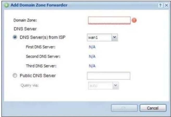
text_image
Add Domain Zone Forwarder Domain Zone: DNS Server DNS Server(s) from ISP wan1 First DNS Server: N/A Second DNS Server: N/A Third DNS Server: N/A Public DNS Server Query via: auto CancelThe following table describes the labels in this screen.
Table 191 Configuration > System > DNS > Domain Zone Forwarder Add/Edit
| LABEL DESCRIPTION | |
| Domain Zone | A domain zone is a fully qualified domain name without the host. For example,zyxel.com.tw is the domain zone for the www.zyxel.com.tw fully qualified domain name.For example, whenever the UAG receives needs to resolve a zyxel.com.tw domain name,it can send a query to the recorded name server IP address.Enter * if all domain zones are served by the specified DNS server(s). |
| DNS Server | Select DNS Server(s) from ISP if your ISP dynamically assigns DNS server information.You also need to select an interface through which the ISP provides the DNS server IPaddress(es). The interface should be activated and set to be a DHCP client. The fieldsbelow display the (read-only) DNS server IP address(es) that the ISP assigns. N/ A displays for any DNS server IP address fields for which the ISP does not assign an IPaddress.Select Public DNS Server if you have the IP address of a DNS server. Enter the DNSserver's IP address in the field to the right. The UAG must be able to connect to the DNSserver without using a VPN tunnel. The DNS server could be on the Internet or one of theUAG's local networks. You cannot use 0.0.0.0. Use the Query via field to select theinterface through which the UAG sends DNS queries to a DNS server.Select Private DNS Server if you have the IP address of a DNS server to which the UAGconnects through a VPN tunnel. Enter the DNS server's IP address in the field to the right.You cannot use 0.0.0.0. |
| OK | Click OK to save your customized settings and exit this screen. |
| Cancel Click Cancel | to exit this screen without saving |
41.6.8 MX Record
A MX (Mail eXchange) record indicates which host is responsible for the mail for a particular domain, that is, controls where mail is sent for that domain. If you do not configure proper MX records for your domain or other domain, external e-mail from other mail servers will not be able to be delivered to your mail server and vice versa. Each host or domain can have only one MX record, that is, one domain is mapping to one host.
41.6.9 Adding/Editing a MX Record
Click the Add icon or select an entry and click the Edit icon in the MX Record table to configure a MX record.
Figure 268 Configuration > System > DNS > MX Record Add/Edit

text_image
Add MX Record Domain Name: IP Address/FQDN: OK CancelThe following table describes the labels in this screen.
Table 192 Configuration > System > DNS > MX Record Add/Edit
| LABEL DESCRIPTION | |
| Domain Name Enter | the domain name where the mail is destined for. |
| IP Address/FQDN | Enter the IP address or Fully-Qualified Domain Name (FQDN) of a mail server that handles the mail for the domain specified in the field above. |
| OK | Click OK to save your customized settings and exit this screen. |
| Cancel Click Cancel | to exit this screen without saving |
41.6.10 Adding/Editing a DNS Service Control Rule
Click the Add icon or select an entry and click the Edit icon in the Service Control table to configure a service control rule.
Figure 269 Configuration > System > DNS > Service Control Rule Add/Edit
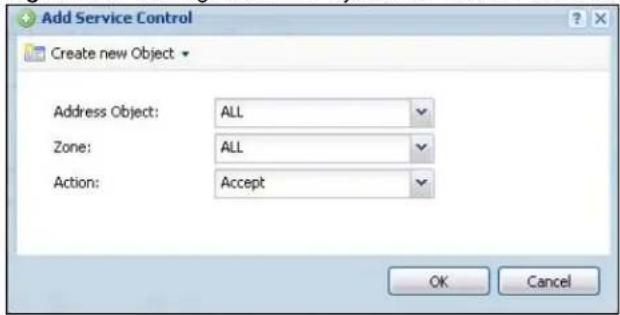
text_image
Add Service Control Create new Object Address Object: ALL Zone: ALL Action: Accept OK CancelThe following table describes the labels in this screen.
Table 193 Configuration > System > DNS > Service Control Rule Add/Edit
| LABEL DESCRIPTION | |
| Create new Object | Use this to configure any new settings objects that you need to use in this screen. |
| Address Object | Select ALL to allow or deny any computer to send DNS queries to the UAG.Select a predefined address object to just allow or deny the computer with the IP address that you specified to send DNS queries to the UAG. |
| Zone | Select ALL to allow or prevent DNS queries through any zones.Select a predefined zone on which a DNS query to the UAG is allowed or denied. |
| Action | Select Accept to have the UAG allow the DNS queries from the specified computer.Select Deny to have the UAG reject the DNS queries from the specified computer. |
| OK | Click OK to save your customized settings and exit this screen. |
| Cancel Click Cancel to exit this screen without saving | |
41.7 WWW Overview
The following figure shows secure and insecure management of the UAG coming in from the WAN. HTTPS and SSH access are secure. HTTP and Telnet access are not secure.
Note: To allow the UAG to be accessed from a specified computer using a service, make sure you do not have a service control rule or to-Device firewall rule to block that traffic.
• See To-Device Rules on page 246 for more on To-Device firewall rules.
To stop a service from accessing the UAG, clear Enable in the corresponding service screen.
41.7.1 Service Access Limitations
A service cannot be used to access the UAG when:
1 You have disabled that service in the corresponding screen.
2 The allowed IP address (address object) in the Service Control table does not match the client IP address (the UAG disallows the session).
3 The IP address (address object) in the Service Control table is not in the allowed zone or the action is set to Deny.
4 There is a firewall rule that blocks it.
41.7.2 System Timeout
There is a lease timeout for administrators. The UAG automatically logs you out if the management session remains idle for longer than this timeout period. The management session does not time out when a statistics screen is polling.
Each user is also forced to log in the UAG for authentication again when the reauthentication time expires.
You can change the timeout settings in the User/ Group screens.
41.7.3 HTTPS
You can set the UAG to use HTTP or HTTPS (HTTPS adds security) for Web Configurator sessions. Specify which zones allow Web Configurator access and from which IP address the access can come.
HTTPS (HyperText Transfer Protocol over Secure Socket Layer, or HTTP over SSL) is a web protocol that encrypts and decrypts web pages. Secure Socket Layer (SSL) is an application-level protocol that enables secure transactions of data by ensuring confidentiality (an unauthorized party cannot read the transferred data), authentication (one party can identify the other party) and data integrity (you know if data has been changed).
It relies upon certificates, public keys, and private keys (see Chapter 39 on page 375 for more information).
HTTPS on the UAG is used so that you can securely access the UAG using the Web Configurator. The SSL protocol specifies that the HTTPS server (the UAG) must always authenticate itself to the HTTPS client (the computer which requests the HTTPS connection with the UAG), whereas the HTTPS client only should authenticate itself when the HTTPS server requires it to do so (select Authenticate Client Certificates in the WWW screen). Authenticate Client Certificates is optional and if selected means the HTTPS client must send the UAG a certificate. You must apply for a certificate for the browser from a CA that is a trusted CA on the UAG.
Please refer to the following figure.
1 HTTPS connection requests from an SSL-aware web browser go to port 443 (by default) on the UAG's web server.
2 HTTP connection requests from a web browser go to port 80 (by default) on the UAG's web server.
Figure 270 HTTP/HTTPS Implementation

text_image
Web Server 443 80 HTTPS HTTPNote: If you disable HTTP in the WWW screen, then the UAG blocks all HTTP connection attempts.
41.7.4 Configuring WWW Service Control
Click Configuration > System > WWW to open the WWW screen. Use this screen to specify from which zones you can access the UAG using HTTP or HTTPS. You can also specify which IP addresses the access can come from.
Note: Admin Service Control deals with management access (to the Web Configurator). User Service Control deals with user access to the UAG (logging into a web portal to access the Internet for example).
Figure 271 Configuration > System > WWW > Service Control
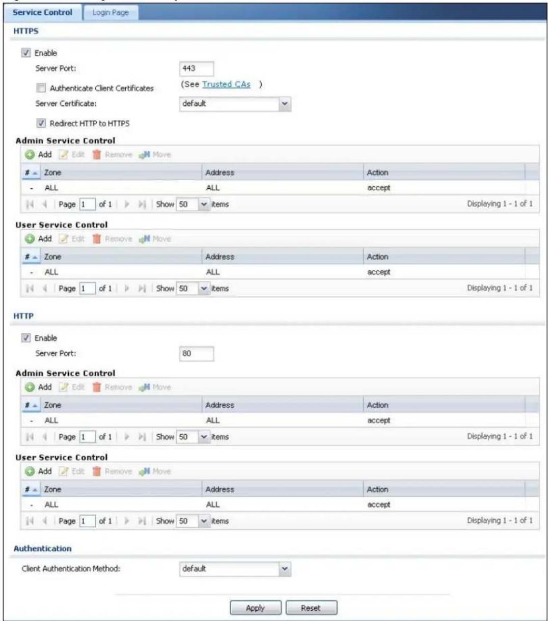
text_image
Service Control Login Page HTTPS Enable Server Port: 443 Authenticate Client Certificates (See Trusted CAs ) Server Certificate: default Redirect HTTP to HTTPS Admin Service Control Add Edit Remove MoveZone Address Action
- ALL ALL accept Page 1 of 1 Show 50 items Displaying 1 - 1 of 1 User Service Control Add Edit Remove MoveZone Address Action
- ALL ALL accept Page 1 of 1 Show 50 items Displaying 1 - 1 of 1 HTTP Enable Server Port: 80 Admin Service Control Add Edit Remove MoveZone Address Action
- ALL ALL accept Page 1 of 1 Show 50 items Displaying 1 - 1 of 1 User Service Control Add Edit Remove MoveZone Address Action
- ALL ALL accept Page 1 of 1 Show 50 items Displaying 1 - 1 of 1 Authentication Client Authentication Method: default Apply ResetThe following table describes the labels in this screen.
Table 194 Configuration > System > WWW > Service Control
| LABEL DESCRIPTION | |
| HTTPS | |
| Enable Select the check | box to allow or disallow the computer with the IP address that matches the IP address(es) in theService Controltable to access the UAG Web Configurator using secure HTTPS connections. |
| Server Port | The HTTPS server listens on port 443 by default. If you change the HTTPS server port to a different number on the UAG, for example 8443, then you must notify people who need to access the UAG Web Configurator to use "https://UAG IP Address:8443" as the URL. |
| Authenticate Client Certificates | Select Authenticate Client Certificates (optional) to require the SSL client to authenticate itself to the UAG by sending the UAG a certificate. To do that the SSL client must have a CA-signed certificate from a CA that has been imported as a trusted CA on the UAG (see Section 41.7.7.5 on page 418 on importing certificates for details). |
| Server Certificate | Select a certificate the HTTPS server (the UAG) uses to authenticate itself to the HTTPS client. You must have certificates already configured in the My Certificates screen. |
| Redirect HTTP to HTTPS | To allow only secure Web Configurator access, select this to redirect all HTTP connection requests to the HTTPS server. |
| Admin/User Service Control | Admin Service Control specifies from which zones an administrator can use HTTPS to manage the UAG (using the Web Configurator). You can also specify the IP addresses from which the administrators can manage the UAG.User Service Control specifies from which zones a user can use HTTPS to log into the UAG (to log into a web portal to access the Internet for example). You can also specify the IP addresses from which the users can access the UAG. |
| Add | Click this to create a new entry. Select an entry and click Add to create a new entry after the selected entry. |
| Edit | Double-click an entry or select it and click Edit to be able to modify the entry's settings. |
| Remove | To remove an entry, select it and click Remove. The UAG confirms you want to remove it before doing so. Note that subsequent entries move up by one when you take this action. |
| Move | To change an entry's position in the numbered list, select the method and click Move to display a field to type a number for where you want to put it and press [ENTER] to move the rule to the number that you typed. |
| # This is the index number of the service control rule.The entry with a hyphen (-) instead of a number is the UAG's (non-configurable) default policy. The UAG applies this to traffic that does not match any other configured rule. It is not an editable rule. To apply other behavior, configure a rule that traffic will match so the UAG will not have to use the default policy. | |
| Zone | This is the zone on the UAG the user is allowed or denied to access. |
| Address | This is the object name of the IP address(es) with which the computer is allowed or denied to access. |
| Action | This displays whether the computer with the IP address specified above can access the UAG zone(s) configured in the Zone field (Accept) or not (Deny). |
| HTTP | |
| Enable Select the check box to allow or disallow the computer with the IP address that matches the IP address(es) in the Service Control table to access the UAG Web Configurator using HTTP connections. | |
| Server Port | You may change the server port number for a service if needed, however you must use the same port number in order to use that service to access the UAG. |
| Admin/User Service Control | Admin Service Control specifies from which zones an administrator can use HTTP to manage the UAG (using the Web Configurator). You can also specify the IP addresses from which the administrators can manage the UAG.User Service Control specifies from which zones a user can use HTTP to log into the UAG (to log into a web portal to access the Internet for example). You can also specify the IP addresses from which the users can access the UAG. |
| Add | Click this to create a new entry. Select an entry and click Add to create a new entry after the selected entry. |
| Edit | Double-click an entry or select it and click Edit to be able to modify the entry's settings. |
| Remove | To remove an entry, select it and click Remove. The UAG confirms you want to remove it before doing so. Note that subsequent entries move up by one when you take this action. |
| Move | To change an entry's position in the numbered list, select the method and click Move to display a field to type a number for where you want to put it and press [ENTER] to move the rule to the number that you typed. |
| # This is the index number of the service control rule.The entry with a hyphen (-) instead of a number is the UAG's (non-configurable) default policy. The UAG applies this to traffic that does not match any other configured rule. It is not an editable rule. To apply other behavior, configure a rule that traffic will match so the UAG will not have to use the default policy. | |
| Zone | This is the zone on the UAG the user is allowed or denied to access. |
| Address | This is the object name of the IP address(es) with which the computer is allowed or denied to access. |
| Action | This displays whether the computer with the IP address specified above can access the UAG zone(s) configured in the Zone field (Accept) or not (Deny). |
| Authentication | |
| Client Authentication Method | Select a method the HTTPS or HTTP server uses to authenticate a client.You must have configured the authentication methods in the Auth. method screen. |
| Apply | Click Apply to save your changes back to the UAG. |
| Reset | Click Reset to return the screen to its last-saved settings. |
41.7.5 Service Control Rules
Click the Add icon or select an entry and click the Edit icon in the Service Control table in a WWW, SSH, Telnet, FTP or SNMP screen to configure a service control rule.
Figure 272 Configuration > System > Service Control Rule > Add/Edit

text_image
Create new Object Address Object: ALL Zone: ALL Action: Accept OK CancelThe following table describes the labels in this screen.
Table 195 Configuration > System > Service Control Rule > Add/Edit
| LABEL DESCRIPTION | |
| Create new Object | Use this to configure any new settings objects that you need to use in this screen. |
| Address Object | Select ALL to allow or deny any computer to communicate with the UAG using this service.Select a predefined address object to just allow or deny the computer with the IP address that you specified to access the UAG using this service. |
| Zone | Select ALL to allow or prevent any UAG zones from being accessed using this service.Select a predefined UAG zone on which a incoming service is allowed or denied. |
| Action | Select Accept to allow the user to access the UAG from the specified computers.Select Deny to block the user's access to the UAG from the specified computers. |
| OK | Click OK to save your customized settings and exit this screen. |
| Cancel Click Cancel to exit this screen without saving | |
41.7.6 Customizing the WWW Login Page
Click Configuration > System > WWW > Login Page to open the Login Page screen. Use this screen to customize the Web Configurator login screen. You can also customize the page that displays after an access user logs into the Web Configurator to access network services like the Internet. See Chapter 32 on page 325 for more on access user accounts.
Figure 273 Configuration > System > WWW > Login Page
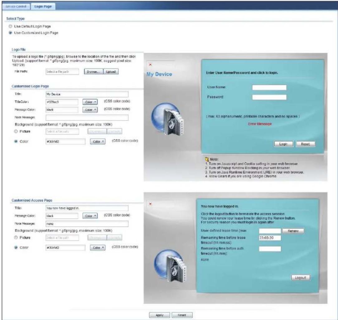
text_image
Service Control Login Page Select Type Use Default Login Page Use Customized Login Page Logo File To upload a logo file (*.gifing.jpg); browse to the location of the file and then click Upload (support format: *gifing.jpg, maximum size: 100K; suggest pixel size: 103*29) File Path: Select a File path Browse... Upload Customized Login Page Title: My Device TitleColor: #378ec3 Color: (CSS color code) Message Color: Black Color: (CSS color code) Note Messages: Background (support format: *gifing.jpg, maximum size: 100K) Picture: Select a file path Update: (CSS color code) Color: #36b/d2 Color: (CSS color code) Enter User Name/Password and click to login. User Name: Password: (max: 63 alphanumeric, printable characters and no spaces) Error Message Login Reset Customized Access Page Title: You now have logged in. Message Color: black Color: (CSS color code) Note Messages: none Background (support format: *gifing.jpg, maximum size: 100K) Picture: Select a file path Update: (CSS color code) Color: #36b/d2 Color: (CSS color code) You now have logged in. Click the logout button to terminate the access session. You could renew your lease time by clicking the Renew button. For security reason you must login in again after. User-defined lease time (max: Renew Remaining time before lease timeout (hh:mm:ss): Remaining time before auth. timeout (hh:mm): none Logout Apply ResetThe following figures identify the parts you can customize in the login and access pages.
Figure 274 Login Page Customization

text_image
Logo Title My Device Enter User Name/Password and click to login. User Name: Password: One-Time Password: (Optional) (max. 63 alphanumeric, printable characters and no spaces ) Error Message Message Color (color of all text) Background Login SSL VPN Note: 1. Tum on Javascript and Cookie setting in your web browser. 2. Turn off Popup Window Blocking in your web browser. 3. Tum on Java Runtime Environment (JRE) in your web browser. 4. Allow Gears if you are using Google Chrome. This is the note you can configure Note Message (last line of text)Figure 275 Access Page Customization
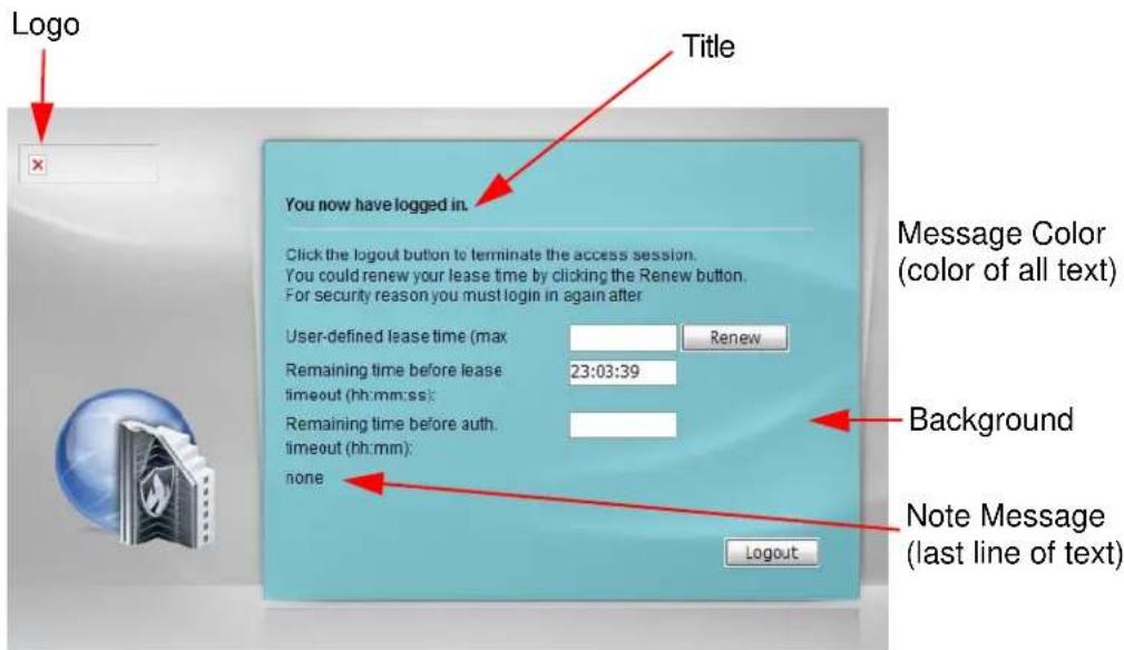
text_image
Logo Title You now have logged in. Click the logout button to terminate the access session. You could renew your lease time by clicking the Renew button. For security reason you must login in again after User-defined lease time (max Renew Remaining time before lease 23:03:39 timeout (hh:mm:ss) Remaining time before auth. timeout (hh:mm): none Message Color (color of all text) Background Note Message (last line of text) LogoutYou can specify colors in one of the following ways:
- Click Color to display a screen of web-safe colors from which to choose.
- Enter the name of the desired color.
- Enter a pound sign (#) followed by the six-digit hexadecimal number that represents the desired color. For example, use “#000000” for black.
- Enter "rgb" followed by red, green, and blue values in parenthesis and separate by commas. For example, use "rgb(0,0,0)" for black.
Your desired color should display in the preview screen on the right after you click in another field, click Apply, or press [ENTER]. If your desired color does not display, your browser may not support it. Try selecting another color.
The following table describes the labels in the screen.
Table 196 Configuration > System > WWW > Login Page
| LABEL DESCRIPTION | |
| Select Type | Select whether the Web Configurator uses the default login screen or one that you customize in the rest of this screen. |
| Logo File You can | upload a graphic logo to be displayed on the upper left corner of the Web Configurator login screen and access page.Specify the location and file name of the logo graphic or clickBrowseto locate it.Note: Use a GIF, JPG, or PNG of 100 kilobytes or less.ClickUploadto transfer the specified graphic file from your computer to the UAG. |
| Customized Login Page | Use this section to set how the Web Configurator login screen looks. |
| Title Enter the title | for the top of the screen. Use up to 64 printable ASCII characters. Spaces are allowed. |
| Title Color Specify | the color of the screen's title text. |
| Message Color Sp | specify the color of the screen's text. |
| Note Message Enter | a note to display at the bottom of the screen. Use up to 64 printable ASCII characters. Spaces are allowed. |
| Background Set how | the screen background looks.To use a graphic, selectPictureand upload a graphic. Specify the location and file name of the logo graphic or clickBrowseto locate it. The picture's size cannot be over 438 x 337 pixels.Note: Use a GIF, JPG, or PNG of 100 kilobytes or less.To use a color, selectColorand specify the color. |
| Customized Access Page | Use this section to customize the page that displays after an access user logs into the Web Configurator to access network services like the Internet. |
| Title Enter the title | for the top of the screen. Use up to 64 printable ASCII characters. Spaces are allowed. |
| Message Color Specify | the color of the screen's text. |
| Note Message Enter | a note to display below the title. Use up to 64 printable ASCII characters. Spaces are allowed. |
| Background Set how | the window's background looks.To use a graphic, selectPictureand upload a graphic. Specify the location and file name of the logo graphic or clickBrowseto locate it. The picture's size cannot be over 438 x 337 pixels.Note: Use a GIF, JPG, or PNG of 100 kilobytes or less.To use a color, selectColorand specify the color. |
Table 196 Configuration > System > WWW > Login Page
| LABEL DESCRIPTION | |
| Apply | Click Apply to save your changes back to the UAG. |
| Reset | Click Reset to return the screen to its last-saved settings. |
41.7.7 HTTPS Example
If you haven't changed the default HTTPS port on the UAG, then in your browser enter "https://UAG IP Address/" as the web site address where "UAG IP Address" is the IP address or domain name of the UAG you wish to access.
41.7.7.1 Internet Explorer Warning Messages
When you attempt to access the UAG HTTPS server, you will see the error message shown in the following screen.
Figure 276 Security Alert Dialog Box (Internet Explorer)

text_image
Certificate Error: Navigation Blocked There is a problem with this website's security certificate. The security certificate presented by this website was not issued by a trusted certificate authority. The security certificate presented by this website was issued for a different website's address. Security certificate problems may indicate an attempt to fool you or intercept any data you send to the server. We recommend that you close this webpage and do not continue to this website. ✓ Click here to close this webpage. ✗ Continue to this website (not recommended). ● More informationSelect Continue to this website to proceed to the Web Configurator login screen. Otherwise, select Click here to close this webpage to block the access.
41.7.7.2 Mozilla Firefox Warning Messages
When you attempt to access the UAG HTTPS server, a The Connection is Untrusted screen appears as shown in the following screen. Click Technical Details if you want to verify more information about the certificate from the UAG.
Select I Understand the Risks and then click Add Exception to add the UAG to the security exception list. Click Confirm Security Exception.
Figure 277 Security Certificate 1 (Firefox)
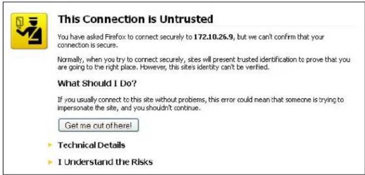
text_image
This Connection is Untrusted You have asked Firefox to connect securely to 172.10.26.9, but we can't confirm that your connection is secure. Normally, when you try to connect securely, sites will present trusted identification to prove that you are going to the right place. However, this sites identity can't be verified. What Should I Do? If you usually connect to this site without problems, this error could mean that someone is trying to impersonate the site, and you shouldn't continue. Get me out of here! ► Technical Details ► I Understand the RisksFigure 278 Security Certificate 2 (Firefox)
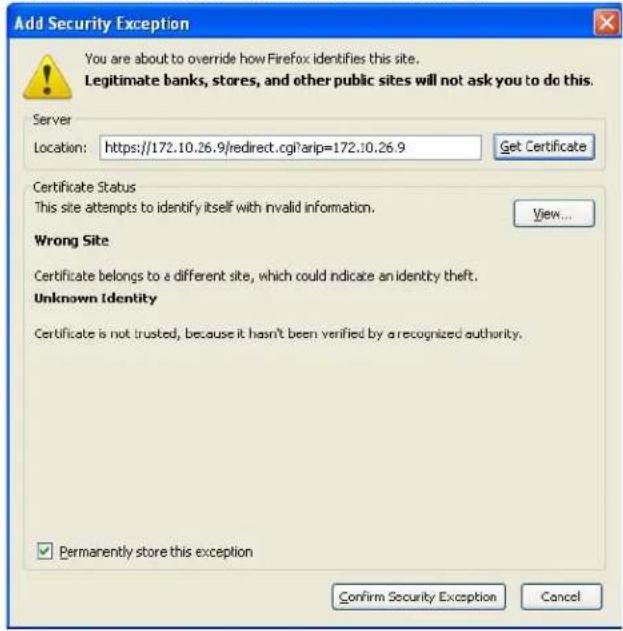
text_image
Add Security Exception You are about to override how Firefox identifies this site. Legitimate banks, stores, and other public sites will not ask you to do this. Server Location: https://172.10.26.9/redirect.cgi?arip=172.10.26.9 Get Certificate Certificate Status This site attempts to identify itself with invalid information. View... Wrong Site Certificate belongs to a different site, which could indicate an identity theft. Unknown Identity Certificate is not trusted, because it hasn't been verified by a recognized authority. ✓ Permanently store this exception Confirm Security Exception Cancel41.7.7.3 Avoiding Browser Warning Messages
Here are the main reasons your browser displays warnings about the UAG's HTTPS server certificate and what you can do to avoid seeing the warnings:
- The issuing certificate authority of the UAG's HTTPS server certificate is not one of the browser's trusted certificate authorities. The issuing certificate authority of the UAG's factory default certificate is the UAG itself since the certificate is a self-signed certificate.
- For the browser to trust a self-signed certificate, import the self-signed certificate into your operating system as a trusted certificate.
- To have the browser trust the certificates issued by a certificate authority, import the certificate authority's certificate into your operating system as a trusted certificate.
41.7.7.4 Login Screen
After you accept the certificate, the UAG login screen appears. The lock displayed in the bottom of the browser status bar denotes a secure connection.
Figure 279 Login Screen (Internet Explorer)
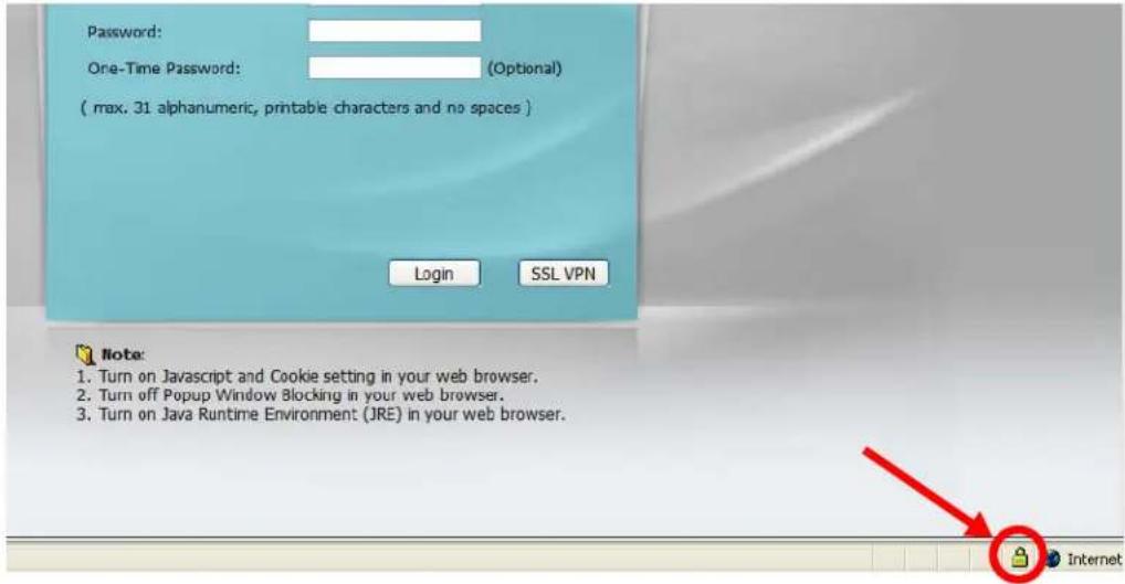
text_image
Password: One-Time Password: (Optional) ( max. 31 alphanumeric, printable characters and no spaces ) Login SSL VPN Note: 1. Turn on Javascript and Cookie setting in your web browser. 2. Turn off Popup Window Blocking in your web browser. 3. Turn on Java Runtime Environment (JRE) in your web browser.41.7.7.5 Enrolling and Importing SSL Client Certificates
The SSL client needs a certificate if Authenticate Client Certificates is selected on the UAG.
You must have imported at least one trusted CA to the UAG in order for the Authenticate Client Certificates to be active (see the Certificates chapter for details).
Apply for a certificate from a Certification Authority (CA) that is trusted by the UAG (see the UAG's Trusted CA Web Configurator screen).
Figure 280 UAG Trusted CA Screen
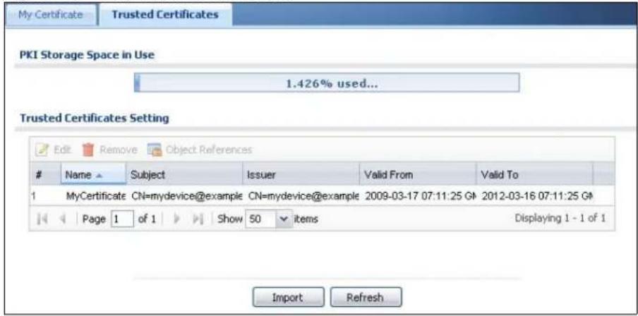
text_image
My Certificate Trusted Certificates PKI Storage Space in Use 1.426% used... Trusted Certificates Setting Edit Remove Object ReferencesName Subject Issuer Valid From Valid To
1 MyCertificate CN=mydevice@example CN=mydevice@example 2009-03-17 07:11:25 G# 2012-03-16 07:11:25 G# Page 1 of 1 Show 50 items Displaying 1 - 1 of 1 Import RefreshThe CA sends you a package containing the CA's trusted certificate(s), your personal certificate(s) and a password to install the personal certificate(s).
41.7.7.5.1 Installing the CA's Certificate
1 Double click the CA's trusted certificate to produce a screen similar to the one shown next.
Figure 281 CA Certificate Example
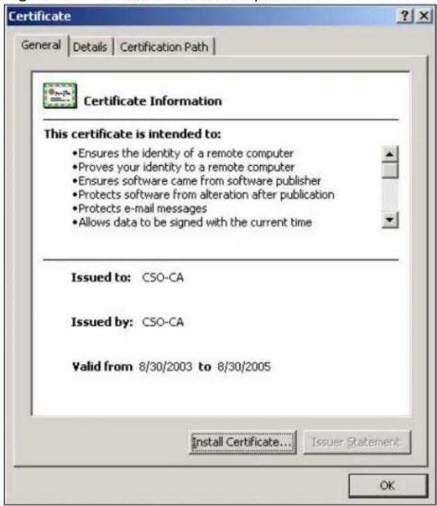
text_image
Certificate General Details Certification Path Certificate Information This certificate is intended to: • Ensures the identity of a remote computer • Proves your identity to a remote computer • Ensures software came from software publisher • Protects software from alteration after publication • Protects e-mail messages • Allows data to be signed with the current time Issued to: CSO-CA Issued by: CSO-CA Valid from 8/30/2003 to 8/30/2005 Install Certificate... Issuer Statement OK2 Click Install Certificate and follow the wizard as shown earlier in this appendix.
41.7.7.5.2 Installing Your Personal Certificate(s)
You need a password in advance. The CA may issue the password or you may have to specify it during the enrollment. Double-click the personal certificate given to you by the CA to produce a screen similar to the one shown next
1 Click Next to begin the wizard.
Figure 282 Personal Certificate Import Wizard 1
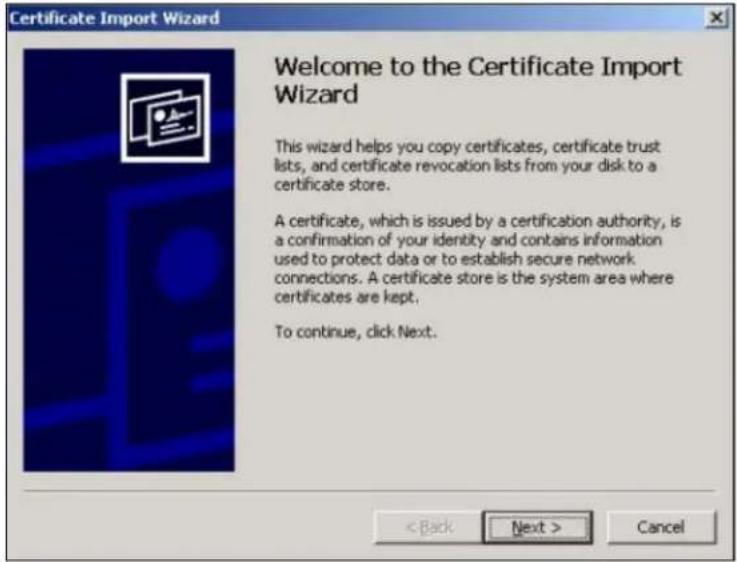
text_image
Certificate Import Wizard Welcome to the Certificate Import Wizard This wizard helps you copy certificates, certificate trust lists, and certificate revocation lists from your disk to a certificate store. A certificate, which is issued by a certification authority, is a confirmation of your identity and contains information used to protect data or to establish secure network connections. A certificate store is the system area where certificates are kept. To continue, click Next. < Back Next > Cancel2 The file name and path of the certificate you double-clicked should automatically appear in the File name text box. Click Browse if you wish to import a different certificate.
Figure 283 Personal Certificate Import Wizard 2
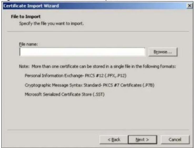
text_image
Certificate Import Wizard File to Import Specify the file you want to import. File name: Browse... Note: More than one certificate can be stored in a single file in the following formats: Personal Information Exchange- PKCS #12 (.PFX,..P12) Cryptographic Message Syntax Standard- PKCS #7 Certificates (.P7B) Microsoft Serialized Certificate Store (.SST) < Back Next > Cancel3 Enter the password given to you by the CA.
Figure 284 Personal Certificate Import Wizard 3
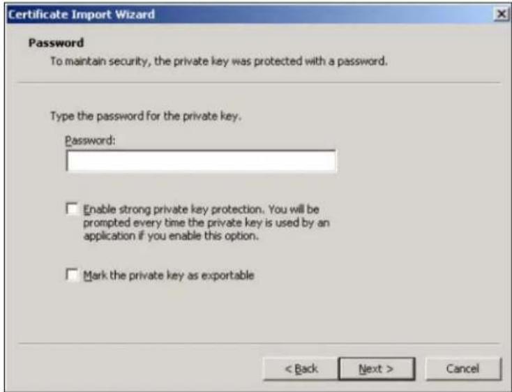
text_image
Certificate Import Wizard Password To maintain security, the private key was protected with a password. Type the password for the private key. Password: Enable strong private key protection. You will be prompted every time the private key is used by an application if you enable this option. Mark the private key as exportable < Back Next > Cancel4 Have the wizard determine where the certificate should be saved on your computer or select Place all certificates in the following store and choose a different location.
Figure 285 Personal Certificate Import Wizard 4
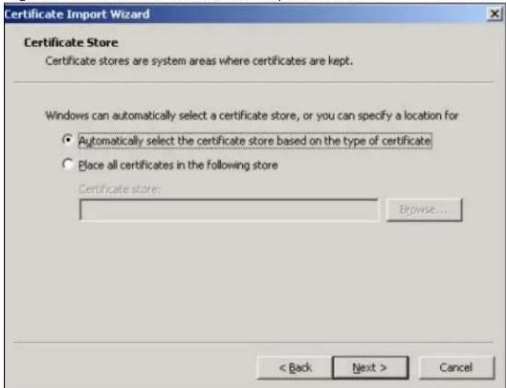
text_image
Certificate Import Wizard Certificate Store Certificate stores are system areas where certificates are kept. Windows can automatically select a certificate store, or you can specify a location for • Automatically select the certificate store based on the type of certificate • Place all certificates in the following store Certificate store: Browse... < Back Next > Cancel5 Click Finish to complete the wizard and begin the import process.
Figure 286 Personal Certificate Import Wizard 5
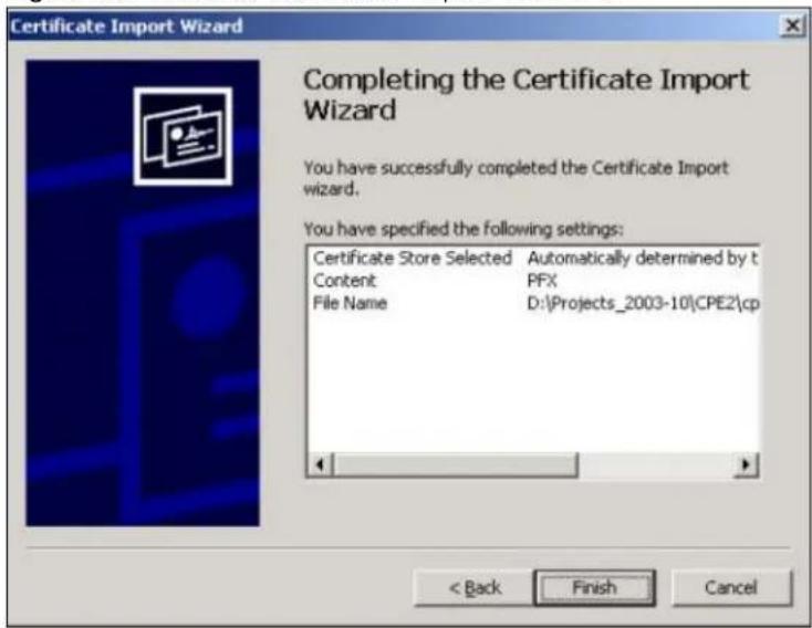
text_image
Certificate Import Wizard Completing the Certificate Import Wizard You have successfully completed the Certificate Import wizard. You have specified the following settings: Certificate Store Selected Automatically determined by t Content PFX File Name D:\Projects_2003-10\CPE2\cp < Back Finish Cancel6 You should see the following screen when the certificate is correctly installed on your computer.
Figure 287 Personal Certificate Import Wizard 6
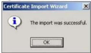
text_image
Certificate Import Wizard The import was successful. OK41.7.7.6 Using a Certificate When Accessing the UAG Example
Use the following procedure to access the UAG via HTTPS.
1 Enter 'https://UAG IP Address/ in your browser's web address field.
Figure 288 Access the UAG Via HTTPS
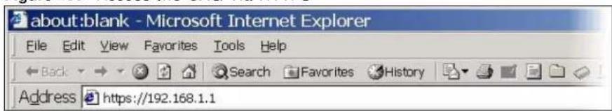
text_image
about:blank - Microsoft Internet Explorer File Edit View Favorites Tools Help Back Search Favorites History Address https://192.168.1.12 When Authenticate Client Certificates is selected on the UAG, the following screen asks you to select a personal certificate to send to the UAG. This screen displays even if you only have a single certificate as in the example.
Figure 289 SSL Client Authentication

text_image
Client Authentication Identification The Web site you want to view requests identification. Select the certificate to use when connecting. testtls More Info... View Certificate... OK Cancel3 You next see the Web Configurator login screen.
Figure 290 Secure Web Configurator Login Screen

text_image
Password: One-Time Password: (Optional) ( max. 31 alphanumeric, printable characters and no spaces ) Login SSL VPN Note: 1. Turn on Javascript and Cookie setting in your web browser. 2. Turn off Popup Window Blocking in your web browser. 3. Turn on Java Runtime Environment (JRE) in your web browser.41.8 SSH
You can use SSH (Secure SHell) to securely access the UAG's command line interface. Specify which zones allow SSH access and from which IP address the access can come.
SSH is a secure communication protocol that combines authentication and data encryption to provide secure encrypted communication between two hosts over an unsecured network. In the following figure, computer A on the Internet uses SSH to securely connect to the WAN port of the UAG for a management session.
Figure 291 SSH Communication Over the WAN Example
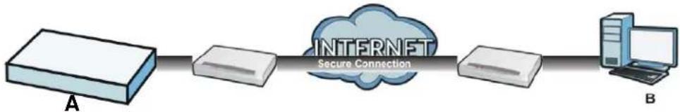
flowchart
graph LR
    A["Server A"] --> B["Router"]
    B --> C["Internet Secure Connection"]
    C --> D["Router D"]
    D --> E["Computer B"]
41.8.1 How SSH Works
The following figure is an example of how a secure connection is established between two remote hosts using SSH v1.
Figure 292 How SSH v1 Works Example
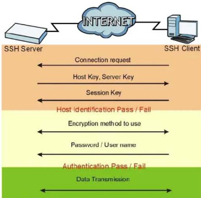
flowchart
graph LR
    A["SSH Server"] --> B["INTERNET"]
    B --> C["SSH Client"]
    D["Connection request"] --> B
    E["Host Key, Server Key"] --> B
    F["Session Key"] --> B
    G["Host Identification Pass / Fail"] --> H["Encryption method to use"]
    I["Password / User name"] --> J["Authentication Pass / Fail"]
    K["Data Transmission"] --> L["Data Transmission"]
1 Host Identification
The SSH client sends a connection request to the SSH server. The server identifies itself with a host key. The client encrypts a randomly generated session key with the host key and server key and sends the result back to the server.
The client automatically saves any new server public keys. In subsequent connections, the server public key is checked against the saved version on the client computer.
2 Encryption Method
Once the identification is verified, both the client and server must agree on the type of encryption method to use.
3 Authentication and Data Transmission
After the identification is verified and data encryption activated, a secure tunnel is established between the client and the server. The client then sends its authentication information (user name and password) to the server to log in to the server.
41.8.2 SSH Implementation on the UAG
Your UAG supports SSH versions 1 and 2 using RSA authentication and four encryption methods (AES, 3DES, Archfour, and Blowfish). The SSH server is implemented on the UAG for management using port 22 (by default).
41.8.3 Requirements for Using SSH
You must install an SSH client program on a client computer (Windows or Linux operating system) that is used to connect to the UAG over SSH.
41.8.4 Configuring SSH
Click Configuration > System > SSH to change your UAG's Secure Shell settings. Use this screen to specify from which zones SSH can be used to manage the UAG. You can also specify from which IP addresses the access can come.
Figure 293 Configuration > System > SSH

text_image
SSH General Settings Enable Version 1 Server Port: 22 Server Certificate: default Service Control Add Edit Remove MoveZone Address Action
- ALL ALL Accept Page 1 of 1 Show 50 items Displaying 1 - 1 of 1 Apply ResetThe following table describes the labels in this screen.
Table 197 Configuration > System > SSH
| LABEL DESCRIPTION | |
| Enable | Select the check box to allow or disallow the computer with the IP address that matches the IP address(es) in the Service Control table to access the UAG CLI using this service. |
| Version 1 | Select the check box to have the UAG use both SSH version 1 and version 2 protocols. If you clear the check box, the UAG uses only SSH version 2 protocol. |
| LABEL | DESCRIPTION |
| Server Port | You may change the server port number for a service if needed, however you must use the same port number in order to use that service for remote management. |
| Server Certificate | Select the certificate whose corresponding private key is to be used to identify the UAG for SSH connections. You must have certificates already configured in the My Certificates screen (See Chapter 39 on page 375 for details). |
| Service Control This specifies from which computers you can access which UAG zones. | |
| Add | Click this to create a new entry. Select an entry and click Add to create a new entry after the selected entry. Refer to Table 195 on page 412 for details on the screen that opens. |
| Edit | Double-click an entry or select it and click Edit to be able to modify the entry's settings. |
| Remove | To remove an entry, select it and click Remove. The UAG confirms you want to remove it before doing so. Note that subsequent entries move up by one when you take this action. |
| Move | To change an entry's position in the numbered list, select the method and click Move to display a field to type a number for where you want to put it and press [ENTER] to move the rule to the number that you typed. |
| # This the index number of the service control rule. | |
| Zone | This is the zone on the UAG the user is allowed or denied to access. |
| Address | This is the object name of the IP address(es) with which the computer is allowed or denied to access. |
| Action | This displays whether the computer with the IP address specified above can access the UAG zone(s) configured in the Zone field (Accept) or not (Deny). |
| Apply | Click Apply to save your changes back to the UAG. |
| Reset | Click Reset to return the screen to its last-saved settings. |
41.8.5 Secure Telnet Using SSH Examples
This section shows two examples using a command interface and a graphical interface SSH client program to remotely access the UAG. The configuration and connection steps are similar for most SSH client programs. Refer to your SSH client program user's guide.
41.8.5.1 Example 1: Microsoft Windows
This section describes how to access the UAG using the Secure Shell Client program.
1 Launch the SSH client and specify the connection information (IP address, port number) for the UAG.
2 Configure the SSH client to accept connection using SSH version 1.
3 A window displays prompting you to store the host key in you computer. Click Yes to continue.
Figure 294 SSH Example 1: Store Host Key
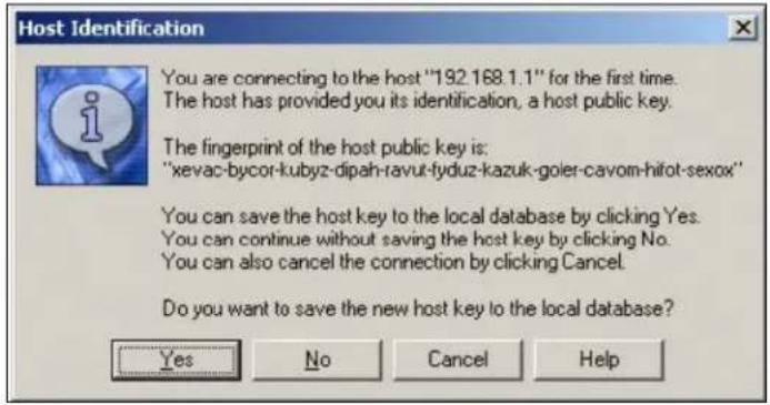
text_image
Host Identification You are connecting to the host "192.168.1.1" for the first time. The host has provided you its identification, a host public key. The fingerprint of the host public key is: "xevac-bycor-kubyz-dipah-ravut-fyduz-kazuk-goler-cavom-hifot-sexox" You can save the host key to the local database by clicking Yes. You can continue without saving the host key by clicking No. You can also cancel the connection by clicking Cancel. Do you want to save the new host key to the local database? Yes No Cancel HelpEnter the password to log in to the UAG. The CLI screen displays next.
41.8.5.2 Example 2: Linux
This section describes how to access the UAG using the OpenSSH client program that comes with most Linux distributions.
1 Test whether the SSH service is available on the UAG.
Enter "telnet 172.16.0.1 22" at a terminal prompt and press [ENTER]. The computer attempts to connect to port 22 on the UAG (using the default IP address of 172.16.0.1).
A message displays indicating the SSH protocol version supported by the UAG.
Figure 295 SSH Example 2: Test
$ telnet 172.16.0.1 22
Trying 172.16.0.1...
Connected to 172.16.0.1.
Escape character is '^]'.
SSH-1.5-1.0.0
2 Enter "ssh -1 172.16.0.1". This command forces your computer to connect to the UAG using SSH version 1. If this is the first time you are connecting to the UAG using SSH, a message displays prompting you to save the host information of the UAG. Type "yes" and press [ENTER].
Then enter the password to log in to the UAG.
Figure 296 SSH Example 2: Log in
$ ssh -1 172.16.0.1
The authenticity of host '172.16.0.1 (172.16.0.1)' can't be established.
RSA1 key fingerprint is 21:6c:07:25:7e:f4:75:80:ec:af:bd:d4:3d:80:53:d1.
Are you sure you want to continue connecting (yes/no)? yes
Warning: Permanently added '172.16.0.1' (RSA1) to the list of known hosts.
Administrator@172.16.0.1's password:
3 The CLI screen displays next.
41.9 Telnet
You can use Telnet to access the UAG's command line interface. Specify which zones allow Telnet access and from which IP address the access can come.
41.9.1 Configuring Telnet
Click Configuration > System > TELNET to configure your UAG for remote Telnet access. Use this screen to specify from which zones Telnet can be used to manage the UAG. You can also specify from which IP addresses the access can come.
Figure 297 Configuration > System > TELNET

text_image
TELNET General Settings Enable Server Port: 23 Service Control Add Edit Remove MoveZone Address Action
- ALL ALL Accept Page 1 of 1 Show 50 items Displaying 1 - 1 of 1 Apply ResetThe following table describes the labels in this screen.
Table 198 Configuration > System > TELNET
| LABEL DESCRIPTION | |
| Enable | Select the check box to allow or disallow the computer with the IP address that matches the IP address(es) in theService Controltable to access the UAG CLI using this service. |
| Server Port | You may change the server port number for a service if needed, however you must use the same port number in order to use that service for remote management. |
| Service Control This specifies from which computers you can access which UAG zones. | |
| Add | Click this to create a new entry. Select an entry and clickAddto create a new entry after the selected entry. Refer toTable 195 on page 412for details on the screen that opens. |
| Edit | Double-click an entry or select it and clickEditto be able to modify the entry's settings. |
| Remove | To remove an entry, select it and clickRemove. The UAG confirms you want to remove it before doing so. Note that subsequent entries move up by one when you take this action. |
| Move | To change an entry's position in the numbered list, select the method and clickMoveto display a field to type a number for where you want to put it and press [ENTER] to move the rule to the number that you typed. |
| # This the index number of the service control rule.The entry with a hyphen (-) instead of a number is the UAG's (non-configurable) default policy. The UAG applies this to traffic that does not match any other configured rule. It is not an editable rule. To apply other behavior, configure a rule that traffic will match so the UAG will not have to use the default policy. | |
| Zone | This is the zone on the UAG the user is allowed or denied to access. |
| Address | This is the object name of the IP address(es) with which the computer is allowed or denied to access. |
| Action | This displays whether the computer with the IP address specified above can access the UAG zone(s) configured in the Zone field (Accept) or not (Deny). |
| Apply | Click Apply to save your changes back to the UAG. |
| Reset | Click Reset to return the screen to its last-saved settings. |
41.10 FTP
You can upload and download the UAG's firmware and configuration files using FTP. To use this feature, your computer must have an FTP client. Please see Chapter 43 on page 450 for more information about firmware and configuration files.
41.10.1 Configuring FTP
To change your UAG's FTP settings, click Configuration > System > FTP tab. The screen appears as shown. Use this screen to specify from which zones FTP can be used to access the UAG. You can also specify from which IP addresses the access can come.
Figure 298 Configuration > System > FTP

text_image
FTP General Settings Enable TLS required Server Port: 21 Server Certificate: default Service Control Add Edit Remove MoveZone Address Action
- ALL ALL Accept Page 1 of 1 Show 50 Items Displaying 1 - 1 of 1 Apply ResetThe following table describes the labels in this screen.
Table 199 Configuration > System > FTP
| LABEL DESCRIPTION | |
| Enable | Select the check box to allow or disallow the computer with the IP address that matches the IP address(es) in the Service Control table to access the UAG using this service. |
| TLS required | Select the check box to use FTP over TLS (Transport Layer Security) to encrypt communication.This implements TLS as a security mechanism to secure FTP clients and/or servers. |
| Server Port | You may change the server port number for a service if needed, however you must use the same port number in order to use that service for remote management. |
| Server Certificate | Select the certificate whose corresponding private key is to be used to identify the UAG for FTP connections. You must have certificates already configured in the My Certificates screen (See Chapter 39 on page 375 for details). |
| Service Control This specifies from which computers you can access which UAG zones. | |
| Add | Click this to create a new entry. Select an entry and click Add to create a new entry after the selected entry. Refer to Table 195 on page 412 for details on the screen that opens. |
| Edit | Double-click an entry or select it and click Edit to be able to modify the entry's settings. |
| Remove | To remove an entry, select it and click Remove. The UAG confirms you want to remove it before doing so. Note that subsequent entries move up by one when you take this action. |
| Move | To change an entry's position in the numbered list, select the method and click Move to display a field to type a number for where you want to put it and press [ENTER] to move the rule to the number that you typed. |
| # This the index number of the service control rule.The entry with a hyphen (-) instead of a number is the UAG's (non-configurable) default policy. The UAG applies this to traffic that does not match any other configured rule. It is not an editable rule. To apply other behavior, configure a rule that traffic will match so the UAG will not have to use the default policy. | |
| Zone | This is the zone on the UAG the user is allowed or denied to access. |
| Address | This is the object name of the IP address(es) with which the computer is allowed or denied to access. |
| Action | This displays whether the computer with the IP address specified above can access the UAG zone(s) configured in the Zone field (Accept) or not (Deny). |
| Apply | Click Apply to save your changes back to the UAG. |
| Reset | Click Reset to return the screen to its last-saved settings. |
41.11 SNMP
Simple Network Management Protocol is a protocol used for exchanging management information between network devices. Your UAG supports SNMP agent functionality, which allows a manager station to manage and monitor the UAG through the network. The UAG supports SNMP version one (SNMPv1) and version two (SNMPv2c). The next figure illustrates an SNMP management operation.
Figure 299 SNMP Management Model

flowchart
graph TD
    A["MANAGER"] --> B["AGENT"]
    A --> C["AGENT"]
    A --> D["AGENT"]
    B --> E["MIB"]
    C --> F["MIB"]
    D --> G["MIB"]
    style A fill:#f9f,stroke:#333
    style B fill:#ccf,stroke:#333
    style C fill:#ccf,stroke:#333
    style D fill:#ccf,stroke:#333
    linkStyle 0 stroke:#000,stroke-width:2px
    linkStyle 1 stroke:#000,stroke-width:2px
    linkStyle 2 stroke:#000,stroke-width:2px
    linkStyle 3 stroke:#000,stroke-width:2px
    linkStyle 4 stroke:#000,stroke-width:2px
    linkStyle 5 stroke:#000,stroke-width:2px
    linkStyle 6 stroke:#000,stroke-width:2px
    linkStyle 7 stroke:#000,stroke-width:2px
    linkStyle 8 stroke:#000,stroke-width:2px
    linkStyle 9 stroke:#000,stroke-width:2px
    linkStyle 10 stroke:#000,stroke-width:2px
    linkStyle 11 stroke:#000,stroke-width:2px
    linkStyle 12 stroke:#000,stroke-width:2px
    linkStyle 13 stroke:#000,stroke-width:2px
    linkStyle 14 stroke:#000,stroke-width:2px
    linkStyle 15 stroke:#000,stroke-width:2px
    linkStyle 16 stroke:#000,stroke-width:2px
    linkStyle 17 stroke:#000,stroke-width:2px
    linkStyle 18 stroke:#000,stroke-width:2px
    linkStyle 19 stroke:#000,stroke-width:2px
    linkStyle 20 stroke:#000,stroke-width:2px
An SNMP managed network consists of two main types of component: agents and a manager.
An agent is a management software module that resides in a managed device (the UAG). An agent translates the local management information from the managed device into a form compatible with SNMP. The manager is the console through which network administrators perform network management functions. It executes applications that control and monitor managed devices.
The managed devices contain object variables/managed objects that define each piece of information to be collected about a device. Examples of variables include such as number of packets received, node port status etc. A Management Information Base (MIB) is a collection of managed objects. SNMP allows a manager and agents to communicate for the purpose of accessing these objects.
SNMP itself is a simple request/response protocol based on the manager/agent model. The manager issues a request and the agent returns responses using the following protocol operations:
- Get - Allows the manager to retrieve an object variable from the agent.
- GetNext - Allows the manager to retrieve the next object variable from a table or list within an agent. In SNMPv1, when a manager wants to retrieve all elements of a table from an agent, it initiates a Get operation, followed by a series of GetNext operations.
- Set - Allows the manager to set values for object variables within an agent.
- Trap - Used by the agent to inform the manager of some events.
41.11.1 Supported MIBs
The UAG supports MIB II that is defined in RFC-1213 and RFC-1215. The UAG also supports private MIBs (private.mib and enterprise.mib) to collect information about CPU and memory usage and VPN total throughput. The focus of the MIBs is to let administrators collect statistical data and monitor status and performance. You can download the UAG's MIBs from www.zyxel.com.
41.11.2 SNMP Traps
The UAG will send traps to the SNMP manager when any one of the following events occurs.
Table 200 SNMP Traps
| OBJECT LABEL OBJECT ID DESCRIPTION | ||
| Cold Start | 1.3.6.1.6.3.1.1.5.1 | This trap is sent when the UAG is turned on or an agent restarts. |
| linkDown 1.3.6.1.6.3.1.1 | .5.3 This trap is sent when the Ethernet link is down. | |
| linkUp 1.3.6.1.6.3.1.1.5.4 | This trap is sent when the Ethernet link is up. | |
| authenticationFailure | 1.3.6.1.6.3.1.1.5.5 | This trap is sent when an SNMP request comes from non-authenticated hosts. |
41.11.3 Configuring SNMP
To change your UAG's SNMP settings, click Configuration > System > SNMP tab. The screen appears as shown. Use this screen to configure your SNMP settings, including from which zones SNMP can be used to access the UAG. You can also specify from which IP addresses the access can come.
Figure 300 Configuration > System > SNMP
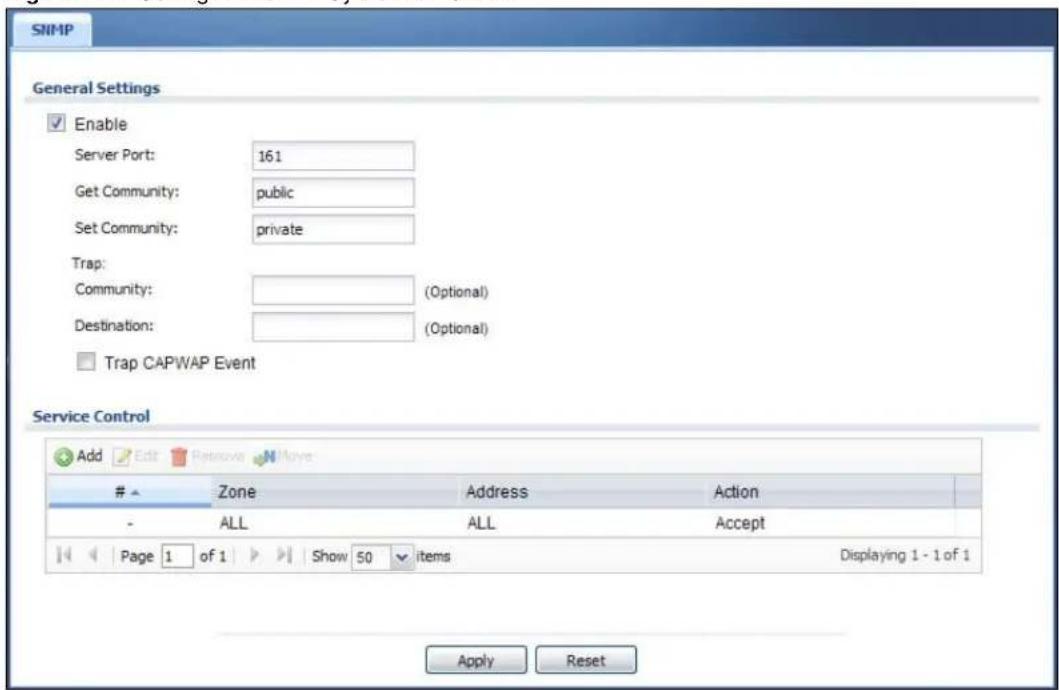
text_image
SNMP General Settings Enable Server Port: 161 Get Community: public Set Community: private Trap: Community: (Optional) Destination: (Optional) Trap CAPWAP Event Service Control Add Edit Remove MoveZone Address Action
- ALL ALL Accept Page 1 of 1 Show 50 items Displaying 1 - 1 of 1 Apply ResetThe following table describes the labels in this screen.
Table 201 Configuration > System > SNMP
| LABEL DESCRIPTION | |
| Enable | Select the check box to allow or disallow the computer with the IP address that matches the IP address(es) in the Service Control table to access the UAG using this service. |
| Server Port | You may change the server port number for a service if needed, however you must use the same port number in order to use that service for remote management. |
| Get Community | Enter the Get Community, which is the password for the incoming Get and GetNext requests from the management station. The default is public and allows all requests. |
| Set Community | Enter the Set community, which is the password for incoming Set requests from the management station. The default is private and allows all requests. |
| Trap | |
| Community | Type the trap community, which is the password sent with each trap to the SNMP manager. The default is public and allows all requests. |
| Destination | Type the IP address of the SNMP manager to which your SNMP traps are sent. |
| Trap CAPWAP Event | Select this option to have the UAG send a trap to the SNMP manager when a managed AP is connected to or disconnected from the UAG. |
| Service Control This specifies from which computers you can access which UAG zones. | |
| Add | Click this to create a new entry. Select an entry and click Add to create a new entry after the selected entry. Refer to Table 195 on page 412 for details on the screen that opens. |
| Edit | Double-click an entry or select it and click Edit to be able to modify the entry's settings. |
| Remove | To remove an entry, select it and click Remove. The UAG confirms you want to remove it before doing so. Note that subsequent entries move up by one when you take this action. |
| Move | To change an entry's position in the numbered list, select the method and click Move to display a field to type a number for where you want to put it and press [ENTER] to move the rule to the number that you typed. |
| # | This the index number of the service control rule.The entry with a hyphen (-) instead of a number is the UAG's (non-configurable) default policy. The UAG applies this to traffic that does not match any other configured rule. It is not an editable rule. To apply other behavior, configure a rule that traffic will match so the UAG will not have to use the default policy. |
| Zone | This is the zone on the UAG the user is allowed or denied to access. |
| Address | This is the object name of the IP address(es) with which the computer is allowed or denied to access. |
| Action | This displays whether the computer with the IP address specified above can access the UAG zone(s) configured in the Zone field (Accept) or not (Deny). |
| Apply | Click Apply to save your changes back to the UAG. |
| Reset | Click Reset to return the screen to its last-saved settings. |
41.12 Language
Click Configuration > System > Language to open this screen. Use this screen to select a display language for the UAG's Web Configurator screens.
Figure 301 Configuration > System > Language
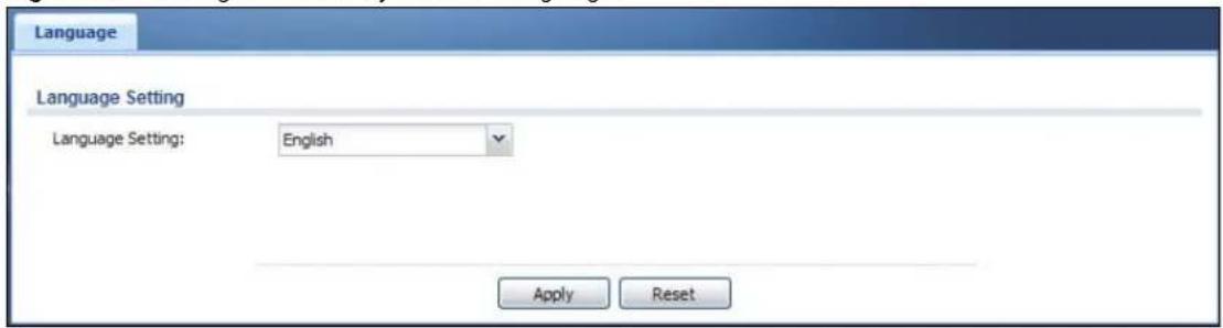
text_image
Language Language Setting Language Setting: English Apply ResetThe following table describes the labels in this screen.
Table 202 Configuration > System > Language
| LABEL DESCRIPTION | |
| Language Setting | Select a display language for the UAG's Web Configurator screens. You also need to open a new browser session to display the screens in the new language. |
| Apply | Click Apply to save your changes back to the UAG. |
| Reset | Click Reset to return the screen to its last-saved settings. |
42.1 Overview
Use these screens to configure daily reporting and log settings.
42.1.1 What You Can Do In this Chapter
- Use the Email Daily Report screen (Section 42.2 on page 435) to configure where and how to send daily reports and what reports to send.
- Use the Log Settings screens (Section 42.3 on page 437) to specify settings for recording log messages and alerts, e-mailing them, storing them on a connected USB storage device, and sending them to remote syslog servers.
42.2 Email Daily Report
Use the Email Daily Report screen to start or stop data collection and view various statistics about traffic passing through your UAG.
Note: Data collection may decrease the UAG's traffic throughput rate.
Click Configuration > Log & Report > Email Daily Report to display the following screen. Configure this screen to have the UAG e-mail you system statistics every day.
Figure 302 Configuration > Log & Report > Email Daily Report

text_image
Email Daily Report General Settings Enable Email Daily Report Email Settings Mail Server: Outgoing SMTP Server Name or IP Address) Mail Subject: Append system name Append date time Mail From: Email Address) Mail To: Email Address) (Email Address) (Email Address) (Email Address) (Smart Report Item) SMTP Authentication User Name : Password: Retype to Confirm: Schedule Time For Sending Report: 0 (hours) 0 (minutes) Report Items System Resource Usage CPU Usage Memory Usage Session Usage Port Usage Wireless Report Station Count TX Statistics RX Statistics Interface Traffic Statistics Reset counters after sending report successfully Reset All Counters Apply ResetThe following table describes the labels in this screen.
Table 203 Configuration > Log & Report > Email Daily Report
| LABEL DESCRIPTION | |
| Enable EmailDaily Report | Select this to send reports by e-mail every day. |
| Mail Server Type the name or IP address of the outgoing SMTP server. | |
| Mail Subject | Type the subject line for the outgoing e-mail. Select Append system name to add the UAG's system name to the subject. Select Append date time to add the UAG's system date and time to the subject. |
| Mail From | Type the e-mail address from which the outgoing e-mail is delivered. This address is used in replies. |
| Mail To | Type the e-mail address (or addresses) to which the outgoing e-mail is delivered. |
| SMTPAuthentication | Select this check box if it is necessary to provide a user name and password to the SMTP server. |
| User Name | This box is effective when you select the SMTP Authentication check box. Type the user name to provide to the SMTP server when the log is e-mailed. |
| Password | This box is effective when you select the SMTP Authentication check box. Type the password to provide to the SMTP server when the log is e-mailed. |
| Retype to Confirm | Retype your new password for confirmation. |
| Send Report Now | Click this button to have the UAG send the daily e-mail report immediately. |
| Time For Sending Report | Select the time of day (hours and minutes) when the log is e-mailed. Use 24-hour notation. |
| Report Items | Select the information to include in the report. Select Reset counters after sending report successfully if you only want to see statistics for a 24 hour period. |
| Reset All Counters | Click this to discard all report data and start all of the counters over at zero. |
| Apply | Click Apply to save your changes back to the UAG. |
| Reset | Click Reset to return the screen to its last-saved settings. |
42.3 Log Settings Screens
The Log Settings screens control log messages and alerts. A log message stores the information for viewing or regular e-mailing later, and an alert is e-mailed immediately. Usually, alerts are used for events that require more serious attention, such as system errors and attacks.
The UAG provides a system log and supports e-mail profiles and remote syslog servers. View the system log in the MONITOR > Log screen. Use the e-mail profiles to mail log messages to the specific destinations. You can also have the UAG store system logs on a connected USB storage device. The other four logs are stored on specified syslog servers.
The Log Settings screens control what information the UAG saves in each log. You can also specify which log messages to e-mail for the system log, and where and how often to e-mail them. These screens also set for which events to generate alerts and where to email the alerts.
The first Log Settings screen provides a settings summary. Use the Edit screens to configure settings such as log categories, e-mail addresses, and server names for any log. Use the Log
Category Settings screen to edit what information is included in the system log, USB storage, e-mail profiles, and remote servers.
42.3.1 Log Settings Summary
To access this screen, click Configuration > Log & Report > Log Settings.
Figure 303 Configuration > Log & Report > Log Settings

text_image
Log Settings Edit Activate InactivateStatus Name Log Format Summary
1 System Log Internal E-mail Server 1 Mail Server: Mail Subject: Send From: Send Log to: Send Alert to: Schedule: Send log when full. 2 System Log Internal E-mail Server 2 Mail Server: Mail Subject: Send From: Send Log to: Send Alert to: Schedule: Send log when full. 3 USB Storage Internal USB Status: none 4 Remote Server 1 VRPT/Syslog Server Address: Log Facility: Local 1 5 Remote Server 2 VRPT/Syslog Server Address: Log Facility: Local 1 6 Remote Server 3 VRPT/Syslog Server Address: Log Facility: Local 1 7 Remote Server 4 VRPT/Syslog Server Address: Log Facility: Local 1 Page 1 of 1 Show 50 items Displaying 1 - 7 of 7 Log Category Settings ApplyThe following table describes the labels in this screen.
Table 204 Configuration > Log & Report > Log Settings
| LABEL DESCRIPTION | |
| Edit | Double-click an entry or select it and click Edit to open a screen where you can modify it. |
| Activate | To turn on an entry, select it and click Activate. |
| Inactivate | To turn off an entry, select it and click Inactivate. |
| # This field | is a sequential value, and it is not associated with a specific log. |
| Status This | icon is lit when the entry is active and dimmed when the entry is inactive. |
| Name | This field displays the type of log setting entry (system log, logs stored on a USB storage device connected to the UAG, or one of the remote servers). |
| Log Format | This field displays the format of the log.Internal - system log; you can view the log on the View Log tab.VRPT/ Syslog - ZyXEL's Vantage Report, syslog-compatible format.CEF/ Syslog - Common Event Format, syslog-compatible format. |
| Summary | This field is a summary of the settings for each log. Please see Section 42.3.2 on page 439 for more information. |
| Log Category Settings | Click this button to open the Log Category Settings screen. |
| Apply | Click this button to save your changes (activate and deactivate logs) and make them take effect. |
42.3.2 Edit System Log Settings
The Log Settings Edit screen controls the detailed settings for each log in the system log (which includes the e-mail profiles). Go to the Log Settings Summary screen (see Section 42.3.1 on page 438), and click the system log Edit icon.
Figure 304 Configuration > Log & Report > Log Settings > Edit (System Log)

text_image
Edit Log Setting E-mail Server 1 Active Mail Server: (Multiping SMTP Server Name or IP Address) Mail Subject: Send From: (E-Mail Address) Send Log to: (E-Mail Address) Send Alerts to: (E-Mail Address) Sending Log: When Full Day for Sending Log: SubId Time for Sending Log: Up To SMTP Authentication User Name: Password: Rename to Confirm: E-mail Server 2. Active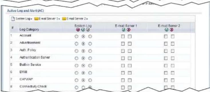
text_image
Page 1 of 1 Show 50 items Displaying 1 - 20 of 20 Log Consolidation Active Log Consolidation Interval (seconds): 10 (10 - 690) OK CancelThe following table describes the labels in this screen.
Table 205 Configuration > Log & Report > Log Settings > Edit (System Log)
| LABEL DESCRIPTION | |
| E-Mail Server 1/2 | |
| Active Select this to | send log messages and alerts according to the information in this section. You specify what kinds of log messages are included in log information and what kinds of log messages are included in alerts in the Active Log and Alert section. |
| Mail Server Type the | name or IP address of the outgoing SMTP server. |
| Mail Subject Type the | subject line for the outgoing e-mail. |
| Send From | Type the e-mail address from which the outgoing e-mail is delivered. This address is used in replies. |
| Send Log To Type the | e-mail address to which the outgoing e-mail is delivered. |
| Send Alerts To Type | the e-mail address to which alerts are delivered. |
| Sending Log | Select how often log information is e-mailed. Choices are: When Full, Hourly and When Full, Daily and When Full, and Weekly and When Full. |
| Day for Sending Log | This field is available if the log is e-mailed weekly. Select the day of the week the log is e-mailed. |
| Time for Sending Log | This field is available if the log is e-mailed weekly or daily. Select the time of day (hours and minutes) when the log is e-mailed. Use 24-hour notation. |
| SMTP Authentication | Select this check box if it is necessary to provide a user name and password to the SMTP server. |
| User Name | This box is effective when you select the SMTP Authentication check box. Type the user name to provide to the SMTP server when the log is e-mailed. |
| Password | This box is effective when you select the SMTP Authentication check box. Type the password to provide to the SMTP server when the log is e-mailed. |
| Retype to Confirm Retype your new password for confirmation. | |
| Active Log and Alert | |
| System Log | Use the System Log drop-down list to change the log settings for all of the log categories.disable all logs(red X)-do not log any information for any category for the system log or e-mail any logs to e-mail server 1 or 2.enable normal logs(green check mark)-create log messages and alerts for all categories for the system log. If e-mail server 1 or 2 also has normal logs enabled, the UAG will e-mail logs to them.enable normal logs and debug logs(yellow check mark)-create log messages, alerts, and debugging information for all categories. The UAG does not e-mail debugging information, even if this setting is selected. |
| E-mail Server 1 | Use the E-Mail Server 1 drop-down list to change the settings for e-mailing logs to e-mail server 1 for all log categories.Using the System Log drop-down list to disable all logs overrides your e-mail server 1 settings.enable normal logs(green check mark)-e-mail log messages for all categories to e-mail server 1.enable alert logs(red exclamation point)-e-mail alerts for all categories to e-mail server 1. |
| E-mail Server 2 | Use the E-Mail Server 2 drop-down list to change the settings for e-mailing logs to e-mail server 2 for all log categories.Using the System Log drop-down list to disable all logs overrides your e-mail server 2 settings.enable normal logs (green check mark) - e-mail log messages for all categories to e-mail server 2.enable alert logs (red exclamation point) - e-mail alerts for all categories to e-mail server 2. |
| # | This field is a sequential value, and it is not associated with a specific address. |
| Log Category | This field displays each category of messages. It is the same value used in the Display and Category fields in the View Log tab. The Default category includes debugging messages generated by open source software. |
| System log | Select which events you want to log by Log Category. There are three choices:disable all logs (red X) - do not log any information from this categoryenable normal logs (green check mark) - create log messages and alerts from this categoryenable normal logs and debug logs (yellow check mark) - create log messages, alerts, and debugging information from this category; the UAG does not e-mail debugging information, however, even if this setting is selected. |
| E-mail Server 1 Select | whether each category of events should be included in the log messages when it is e-mailed (green check mark) and/or in alerts (red exclamation point) for the e-mail settings specified in E-Mail Server 1. The UAG does not e-mail debugging information, even if it is recorded in the System log. |
| E-mail Server 2 Select | whether each category of events should be included in log messages when it is e-mailed (green check mark) and/or in alerts (red exclamation point) for the e-mail settings specified in E-Mail Server 2. The UAG does not e-mail debugging information, even if it is recorded in the System log. |
| Log Consolidation | |
| Active Select this to | activate log consolidation. Log consolidation aggregates multiple log messages that arrive within the specified Log Consolidation Interval. In the View Log tab, the text "[count= x]", where x is the number of original log messages, is appended at the end of the Message field, when multiple log messages were aggregated. |
| Log Consolidation Interval | Type how often, in seconds, to consolidate log information. If the same log message appears multiple times, it is aggregated into one log message with the text "[count= x]", where x is the number of original log messages, appended at the end of the Message field. |
| OK | Click this to save your changes and return to the previous screen. |
| Cancel Click this to return to the previous screen without saving your changes. | |
42.3.3 Edit Log on USB Storage Setting
The Edit Log on USB Storage Setting screen controls the detailed settings for saving logs to a connected USB storage device. Go to the Log Setting Summary screen (see Section 42.3.1 on page 438), and click the USB storage Edit icon.
Figure 305 Configuration > Log & Report > Log Settings > Edit (USB Storage)

text_image
Edit Log on USB Storage Setting USB Storage Duplicate logs to USB storage (if ready) Log Keep duration Enable log keep duration Keep duration: 365 (1-365 days) Active Log Selection # Log Category Selection 1 Account 2 Advertisement 3 Auth. Policy 4 Authentication Server 5 Built-In Service 6 BWM 7 CAPWAP 8 Connectivity Check 9 Daily Report 10 Default 11 DHCP 12 Dynamic Guest Account Page 1 of 1 Show 50 items Displaying 1 - 41 of 41 OK CancelThe following table describes the labels in this screen.
Table 206 Configuration > Log & Report > Log Settings > Edit (USB Storage)
| LABEL DESCRIPTION | |
| Duplicate logs to USB storage (if ready) | Select this to have the UAG save a copy of its system logs to a connected USB storage device. Use the Active Log section to specify what kinds of messages to include. |
| Enable log keep duration | Select this option to have the UAG save a copy of its system logs to a connected USB storage device on a daily basis. |
| Keep duration | Specify how long the UAG is to keep the copy of system logs in the connected USB storage device before discarding it. |
| Active Log | |
| Selection | Use the Selection drop-down list to change the log settings for all of the log categories.disable all logs(red X)- do not send the remote server logs for any log category.enable normal logs(green check mark)- send the remote server log messages and alerts for all log categories.enable normal logs and debug logs(yellow check mark)- send the remote server log messages, alerts, and debugging information for all log categories. |
| # This field is a sequential value, and it is not associated with a specific entry. | |
| Log Category | This field displays each category of messages. The Default category includes debugging messages generated by open source software. |
| Selection | Select what information you want to log from each Log Category (except All Logs; see below). Choices are:disable all logs(red X) - do not log any information from this categoryenable normal logs(green check mark) - log regular information and alerts from this categoryenable normal logs and debug logs(yellow check mark) - log regular information, alerts, and debugging information from this category |
| OK Click this to save your changes and return to the previous screen. | |
| Cancel Click this to return to the previous screen without saving your changes. | |
42.3.4 Edit Remote Server Log Settings
The Log Settings Edit screen controls the detailed settings for each log in the remote server (syslog). Go to the Log Settings Summary screen (see Section 42.3.1 on page 438), and click a remote server Edit icon.
Figure 306 Configuration > Log & Report > Log Settings > Edit (Remote Server)

text_image
Edit Remote Server 1 Log Settings for Remote Server Active Log Format: VRPT/Syslog Server Address: (Server Name or IP Address) Log Facility: Local 1 Active Log (AC) Selection +Log Category Selection
1 Account ○ ○ ○ 2 Advertisement ○ ○ ○ 3 Auth. Policy ○ ○ ○ 4 Authentication Server ○ ○ ○ 5 Built-in Service ○ ○ ○ 6 BWM ○ ○ ○ 7 CAPWAP ○ ○ ○ 8 Connectivity Check ○ ○ ○ 9 Daily Report ○ ○ ○ 10 Default ○ ○ ○ Page 1 of 1 Show 50 items Displaying 1 - 33 of 33 Active Log (AP) Selection +Log Category Selection
1 Account ○ ○ ○ 2 Built-in Service ○ ○ ○ 3 CAPWAP ○ ○ ○ 4 Daily Report ○ ○ ○ 5 Default ○ ○ ○ 6 DHCP ○ ○ ○ 7 File Manager ○ ○ ○ 8 Force Authentication ○ ○ ○ 9 Interface ○ ○ ○ 10 Interface Statistics ○ ○ ○ 11 PKI ○ ○ ○ 23 ZySH ○ ○ Page 1 of 1 Show 50 items Displaying 1 - 23 of 23 OK CancelThe following table describes the labels in this screen.
Table 207 Configuration > Log & Report > Log Setting > Edit (Remote Server)
| LABEL DESCRIPTION | |
| Log Settings for Remote Server | |
| Active | Select this check box to send log information according to the information in this section. You specify what kinds of messages are included in log information in the Active Log section. |
| Log Format This field displays the format of the log information.VRPT/ Syslog - ZyXEL's Vantage Report, syslog-compatible format.CEF/ Syslog - Common Event Format, syslog-compatible format. | |
| Server Address | Type the server name or the IP address of the syslog server to which to send log information. |
| Log Facility | Select a log facility. The log facility allows you to log the messages to different files in the syslog server. Please see the documentation for your syslog program for more information. |
| Active Log | |
| Selection | Use the Selection drop-down list to change the log settings for all of the log categories.disable all logs(red X) - do not send the remote server logs for any log category.enable normal logs(green check mark) - send the remote server log messages and alerts for all log categories.enable normal logs and debug logs(yellow check mark) - send the remote server log messages, alerts, and debugging information for all log categories. |
| # This field is a sequential value, and it is not associated with a specific address. | |
| Log Category | This field displays each category of messages. It is the same value used in the Display and Category fields in the View Log tab. The Default category includes debugging messages generated by open source software. |
| Selection | Select what information you want to log from each Log Category(except All Logs; see below). Choices are:disable all logs(red X) - do not log any information from this categoryenable normal logs(green check mark) - log regular information and alerts from this categoryenable normal logs and debug logs(yellow check mark) - log regular information, alerts, and debugging information from this category |
| OK | Click this to save your changes and return to the previous screen. |
| Cancel Click this to return to the previous screen without saving your changes. | |
42.3.5 Log Category Settings Screen
This screen allows you to view and to edit what information is included in the system log, USB storage, e-mail profiles, and remote servers at the same time. It does not let you change other log settings (for example, where and how often log information is e-mailed or remote server names). To access this screen, go to the Log Settings Summary screen (see Section 42.3.1 on page 438), and click the Log Category Settings button.
Figure 307 Configuration > Log & Report > Log Setting > Log Category Settings

text_image
Log Category Settings Log Category Settings (AC) System Log - USB Storage - E-mail Server 1 - E-mail Server 2 - Remote Server 1 - Remote Server 2 - Remote Server 3 - Remote Server 4 -Log Category System Log USB Storage E-mail Serve... E-mail Serve... Remote Serv... Remote Serv... Remote Serv... Remote Serv...
- - - E-Mail E-Mail Systlog Systlog Systlog Syslog Syslog Syslog 1 Account ○ ○ ○ ○ ○ ○ □ □ □ ○ ○ ○ ○ ○ ○ ● ○ ○ ○ ○ 2 Captive Portal ○ ○ ○ ○ ○ ○ □ □ □ ○ ○ ○ ○ ○ ○ ● ○ ○ ○ ○ 3 Authentication... ○ ○ ○ ○ ○ ○ □ □ □ ○ ○ ○ ○ ○ ○ ● ○ ○ ○ ○ 4 Built-In Send ... ○ ○ ○ ○ ○ ○ □ □ □ ○ ○ ○ ○ ○ ○ ● ○ ○ ○ ○ 5 CAP/WAP ○ ○ ○ ○ ○ ○ □ □ □ ○ ○ ○ ○ ○ ○ ● ○ ○ ○ ○ 6 Connectivity... ○ ○ ○ ○ ○ ○ □ □ □ ○ ○ ○ ○ ○ ● ○ ○ ○ 7 Daily Report ○ ○ ○ ● ○ ○ □ □ □ ○ ○ ○ ● ○ ○ ● ● ○ ◯ 8 Default ○ ○ ● ● ○ ○ □ □ □ ○ ○ ◯ ◯ ◯ ◯ ◯ ◯ ◯ ◯ ◯ ◯ ◯ ◯ ◯ ◯ ◯ ◯ ◯ ◯ ◯ ◯ ◯ ◯ ◯ ◯ ◯ ◯ ◯ ◯ ◯ ◯ ◯ ◯ ◯ ◯ ◯ ◯ ◯ ◯ ◯ ◯ ◯ ◯ ◯ ◯ ◯ ◯ ◯ ◯ ◯ ◯ ◉ 9 DHCP ● ● ● ● ● ● ● □ □ □ ● ● ● ● ● ● ● ● ● ● ● ● ● ● ● ● ● ● ● ● ● ● ● ● ● ● ● ● ● ● ● ● ● ● ● ● ● ● ● ● ● ● ● ● ● ● ● ● ● ● ● ● ● ● ● ● ● ● ● ● ● ● ● ● ● ● ● ● ● ● ● ● ● ● ● ● ● ● ● ● ● ● ● ● ● ● ● ● ● ● ● ● ● ● ● ● ● ● ● ●● 10 Dynamic 33 ZySH Page 1 of 1 Show 50 items Displaying 1 - 33 of 33 Log Category Settings (AP) System Log - E-mail Server 1 - E-mail Server 2 - Remote Server 1 - Remote Server 2 - Remote Server 3 - Remote Server 4 -Log Category System Log E-mail Server 1 E-mail E-mail E-mail Remote Server... Remote Server... Remote Server... Remote Server... Remote Server...
- - - E-Mail E-Mail Systlog Systlog Systlog Syslog Syslog Syslog Syslog Syslog Syslog Syslog Syslog Syslog Syslog Syslog Syslog Syslog Syslog Syslog Syslog Syslog Syslog Syslog Syslog Syslog Syslog Syslog Syslog Syslog Syslog Syslog Syslog Syslog Syslog Syslog Syslog Syslog Syslog Syslog Syslog Syslog Syslog Syslog Syslog Syslog Syslog Syslog Syslog Syslog Syslog Syslog Syslog Syslog SyslogSyslog 1 Account ○○○○□□□□○○○○○○○ 2 Built-in Service ○○○○□□□□○○○○○○○○○○○○○ 3 CAP/WAP ○○○○□□□□○○○○○○○○○○○○○ 4 Daily Report ○○○○□□□□○○○○○○○○○○○○○ 5 Default ○○○□□□□○○○○○○○○○○○○ 6 DHCP ○○○□□□□○○○○○○○○○○ 7 File Manager ○●○□□□□●○○●●●●●●●●●●●●●●●●●●●●●●●●●●●●●●●●●●●●●●●●●●●●●●●●●●●●●●●●●●●●●●●●●●●●●●●●●●●●●●●●●●●●●●●●●●●●●●●●●●●● 23 ZySH Page 1 of 1 Show 50 items Displaying 1 - 23 of 23 OK CancelThis screen provides a different view and a different way of indicating which messages are included in each log and each alert. Please see Section 42.3.2 on page 439, where this process is discussed. (The Default category includes debugging messages generated by open source software.)
The following table describes the fields in this screen.
Table 208 Configuration > Log & Report > Log Setting > Log Category Settings
| LABEL DESCRIPTION | |
| System Log | Use the System Log drop-down list to change the log settings for all of the log categories. disable all logs (red X) - do not log any information for any category for the system log or e-mail any logs to e-mail server 1 or 2. enable normal logs (green check mark) - create log messages and alerts for all categories for the system log. If e-mail server 1 or 2 also has normal logs enabled, the UAG will e-mail logs to them. enable normal logs and debug logs (yellow check mark) - create log messages, alerts, and debugging information for all categories. The UAG does not e-mail debugging information, even if this setting is selected. |
| USB Storage | Use the USB Storage drop-down list to change the log settings for saving logs to a connected USB storage device. disable all logs (red X) - do not log any information for any category to a connected USB storage device. enable normal logs (green check mark) - create log messages and alerts for all categories and save them to a connected USB storage device. enable normal logs and debug logs (yellow check mark) - create log messages, alerts, and debugging information for all categories and save them to a connected USB storage device. |
| E-mail Server 1 | Use the E-Mail Server 1 drop-down list to change the settings for e-mailing logs to e-mail server 1 for all log categories. Using the System Log drop-down list to disable all logs overrides your e-mail server 1 settings. enable normal logs (green check mark) - e-mail log messages for all categories to e-mail server 1. enable alert logs (red exclamation point) - e-mail alerts for all categories to e-mail server 1. |
| E-mail Server 2 | Use the E-Mail Server 2 drop-down list to change the settings for e-mailing logs to e-mail server 2 for all log categories. Using the System Log drop-down list to disable all logs overrides your e-mail server 2 settings. enable normal logs (green check mark) - e-mail log messages for all categories to e-mail server 2. enable alert logs (red exclamation point) - e-mail alerts for all categories to e-mail server 2. |
| Remote Server 1~4 | For each remote server, use the Selection drop-down list to change the log settings for all of the log categories. disable all logs (red X) - do not send the remote server logs for any log category. enable normal logs (green check mark) - send the remote server log messages and alerts for all log categories. enable normal logs and debug logs (yellow check mark) - send the remote server log messages, alerts, and debugging information for all log categories. |
| # | This field is a sequential value, and it is not associated with a specific address. |
| Log Category | This field displays each category of messages. It is the same value used in the Display and Category fields in the View Log tab. The Default category includes debugging messages generated by open source software. |
| System Log | Select which events you want to log byLog Category. There are three choices:disable all logs(red X) - do not log any information from this categoryenable normal logs(green check mark) - create log messages and alerts from this categoryenable normal logs and debug logs(yellow check mark) - create log messages, alerts, and debugging information from this category; the UAG does not e-mail debugging information, however, even if this setting is selected. |
| USB Storage | Select which event log categories to save to a connected USB storage device. There are three choices:disable all logs(red X) - do not log any information from this categoryenable normal logs(green check mark) - save log messages and alerts from this categoryenable normal logs and debug logs(yellow check mark) - save log messages, alerts, and debugging information from this category. |
| E-mail Server 1E-mail | Select whether each category of events should be included in the log messages when it is e-mailed (green check mark) and/or in alerts (red exclamation point) for the e-mail settings specified inE-Mail Server 1. The UAG does not e-mail debugging information, even if it is recorded in theSystem log. |
| E-mail Server 2E-mail | Select whether each category of events should be included in log messages when it is e-mailed (green check mark) and/or in alerts (red exclamation point) for the e-mail settings specified inE-Mail Server 2. The UAG does not e-mail debugging information, even if it is recorded in theSystem log. |
| Remote Server 1~4 Syslog | For each remote server, select what information you want to log from eachLog Category(exceptAll Logs; see below). Choices are:disable all logs(red X) - do not log any information from this categoryenable normal logs(green check mark) - log regular information and alerts from this categoryenable normal logs and debug logs(yellow check mark) - log regular information, alerts, and debugging information from this category |
| OK | Click this to save your changes and return to the previous screen. |
| Cancel Click this | to return to the previous screen without saving your changes. |
43.1 Overview
Configuration files define the UAG's settings. Shell scripts are files of commands that you can store on the UAG and run when you need them. You can apply a configuration file or run a shell script without the UAG restarting. You can store multiple configuration files and shell script files on the UAG. You can edit configuration files or shell scripts in a text editor and upload them to the UAG. Configuration files use a .conf extension and shell scripts use a .zysh extension.
43.1.1 What You Can Do in this Chapter
- Use the Configuration File screen (see Section 43.2 on page 452) to store and name configuration files. You can also download configuration files from the UAG to your computer and upload configuration files from your computer to the UAG.
- Use the Firmware Package screen (see Section 43.3 on page 456) to check your current firmware version and upload firmware to the UAG.
- Use the Shell Script screen (see Section 43.4 on page 458) to store, name, download, upload and run shell script files.
43.1.2 What you Need to Know
Configuration Files and Shell Scripts
When you apply a configuration file, the UAG uses the factory default settings for any features that the configuration file does not include. When you run a shell script, the UAG only applies the commands that it contains. Other settings do not change.
These files have the same syntax, which is also identical to the way you run CLI commands manually. An example is shown below.
Figure 308 Configuration File / Shell Script: Example
<h1 id="enter-configuration-mode">enter configuration mode</h1>
configure terminal
<h1 id="change-administrator-password">change administrator password</h1>
username admin password 4321 user-type admin
<h1 id="configure-wanl">configure wanl</h1>
interface wanl
ip address 10.16.17.240 255.255.255.0
ip gateway 10.16.17.254 metric 1
exit
<h1 id="create-address-objects-for-remote-management-to-device-firewall-rules">create address objects for remote management / to-Device firewall rules</h1>
<h1 id="use-the-address-group-in-case-we-want-to-open-up-remote-management-later">use the address group in case we want to open up remote management later</h1>
address-object TW_SUBNET 10.16.37.0/24
object-group address TW_TEAM
address-object TW_SUBNET
exit
<h1 id="enable-telnet-access-not-enabled-by-default-unlike-other-services">enable Telnet access (not enabled by default, unlike other services)</h1>
ip telnet server
<h1 id="open-wan-to-device-firewall-for-tw_team-for-remote-management">open WAN-to-Device firewall for TW_TEAM for remote management</h1>
firewall WAN Device insert 4
sourceip TW_TEAM
service TELNET
action allow
exit
write
While configuration files and shell scripts have the same syntax, the UAG applies configuration files differently than it runs shell scripts. This is explained below.
Table 209 Configuration Files and Shell Scripts in the UAG
Configuration Files (.conf) Shell Scripts (.zysh)

• Resets to default configuration.
• G o e s i n t o C L I Configuration mode commands in the shell script.
• Runs the commands in the configuration file.
You have to run the example in Figure 308 on page 451 as a shell script because the first command is run in Privilege mode. If you remove the first command, you have to run the example as a configuration file because the rest of the commands are executed in Configuration mode.
Comments in Configuration Files or Shell Scripts
In a configuration file or shell script, use “#” or “!” as the first character of a command line to have the UAG treat the line as a comment.
Your configuration files or shell scripts can use "exit" or a command line consisting of a single "!" to have the UAG exit sub command mode.
Note: “exit” or “!” must follow sub commands if it is to make the UAG exit sub command mode.
Line 3 in the following example exits sub command mode.
interface lan1
ip address dhcp
!
Lines 1 and 3 in the following example are comments and line 4 exits sub command mode.
!
interface lan1
<h1 id="this-interface-is-a-dhcp-client">this interface is a DHCP client</h1>
!
Lines 1 and 2 are comments. Line 5 exits sub command mode.
! this is from Joe
<h1 id="on-20080405">on 2008/04/05</h1>
interface lan1
ip address dhcp
!
Errors in Configuration Files or Shell Scripts
When you apply a configuration file or run a shell script, the UAG processes the file line-by-line. The UAG checks the first line and applies the line if no errors are detected. Then it continues with the next line. If the UAG finds an error, it stops applying the configuration file or shell script and generates a log.
You can change the way a configuration file or shell script is applied. Include setenv stop-on-error off in the configuration file or shell script. The UAG ignores any errors in the configuration file or shell script and applies all of the valid commands. The UAG still generates a log for any errors.
43.2 The Configuration File Screen
Click Maintenance > File Manager > Configuration File to open the Configuration File screen. Use the Configuration File screen to store, run, and name configuration files. You can also download configuration files from the UAG to your computer and upload configuration files from your computer to the UAG.
Once your UAG is configured and functioning properly, it is highly recommended that you back up your configuration file before making further configuration changes. The backup configuration file will be useful in case you need to return to your previous settings.
Configuration File Flow at Restart
- If there is not a startup-config.conf when you restart the UAG (whether through a management interface or by physically turning the power off and back on), the UAG uses the system-default.conf configuration file with the UAG's default settings.
- If there is a startup-config.conf, the UAG checks it for errors and applies it. If there are no errors, the UAG uses it and copies it to the lastgood.conf configuration file as a back up file. If there is an error, the UAG generates a log and copies the startup-config.conf configuration file to the startup-config-bad.conf configuration file and tries the existing lastgood.conf configuration file. If there isn't a lastgood.conf configuration file or it also has an error, the UAG applies the system-default.conf configuration file.
- You can change the way the startup-config.conf file is applied. Include the setenv-startup stop-on-error off command. The UAG ignores any errors in the startup-config.conf file and applies all of the valid commands. The UAG still generates a log for any errors.
Figure 309 Maintenance > File Manager > Configuration File
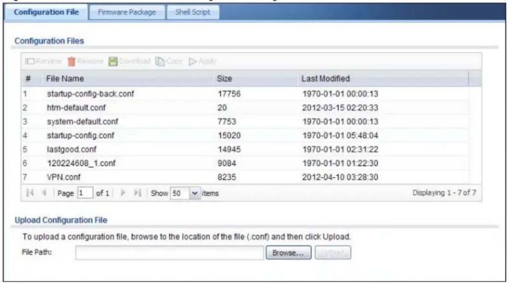
text_image
Configuration FilesFile Name Size Last Modified
1 startup-config-back.conf 17756 1970-01-01 00:00:13 2 htm-default.conf 20 2012-03-15 02:20:33 3 system-default.conf 7753 1970-01-01 00:00:13 4 startup-config.conf 15020 1970-01-01 05:48:04 5 lastgood.conf 14945 1970-01-01 02:31:22 6 120224608_1.conf 9084 1970-01-01 01:22:30 7 VPN.conf 8235 2012-04-10 03:28:30 Page 1 of 1 Show 50 items Displaying 1 - 7 of 7 Upload Configuration File To upload a configuration file, browse to the location of the file (.conf) and then click Upload. File Path: Browse... UpgradeDo not turn off the UAG while configuration file upload is in progress.
The following table describes the labels in this screen.
Table 210 Maintenance > File Manager > Configuration File
| LABEL DESCRIPTION | |
| Rename | Use this button to change the label of a configuration file on the UAG. You can only rename manually saved configuration files. You cannot rename the lastgood.conf, system-default.conf and startup-config.conf files.You cannot rename a configuration file to the name of another configuration file in the UAG.Click a configuration file's row to select it and click Rename to open the Rename File screen.Figure 310 Maintenance > File Manager > Configuration File > Rename Specify the new name for the configuration file. Use up to 25 characters (including a-zA-Z0-9;~!@#%^&()_+[]',= -).Click OK to save the duplicate or click Cancel to close the screen without saving a duplicate of the configuration file. Specify the new name for the configuration file. Use up to 25 characters (including a-zA-Z0-9;~!@#%^&()_+[]',= -).Click OK to save the duplicate or click Cancel to close the screen without saving a duplicate of the configuration file. |
| Remove | Click a configuration file's row to select it and click Remove to delete it from the UAG. You can only delete manually saved configuration files. You cannot delete the system-default.conf, startup-config.conf and lastgood.conf files.A pop-up window asks you to confirm that you want to delete the configuration file. Click OK to delete the configuration file or click Cancel to close the screen without deleting the configuration file. |
| Download | Click a configuration file's row to select it and click Download to save the configuration to your computer. |
| Copy | Use this button to save a duplicate of a configuration file on the UAG.Click a configuration file's row to select it and click Copy to open the Copy File screen.Figure 311 Maintenance > File Manager > Configuration File > Copy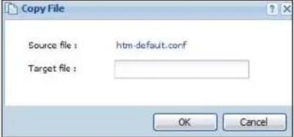 Specify a name for the duplicate configuration file. Use up to 25 characters (including a-zA-Z0-9;~!@#%^&()_+[]{}',= -).Click OK to save the duplicate or click Cancel to close the screen without saving a duplicate of the configuration file. Specify a name for the duplicate configuration file. Use up to 25 characters (including a-zA-Z0-9;~!@#%^&()_+[]{}',= -).Click OK to save the duplicate or click Cancel to close the screen without saving a duplicate of the configuration file. |
Specify the new name for the configuration file. Use up to 25 characters (including a-zA-Z0-9;\~!@# \$%^ &()_+[]{}',= -).
Click OK to save the duplicate or click Cancel to close the screen without saving a duplicate of the configuration file.
Click a configuration file's row to select it and click Remove to delete it from the UAG. You can only delete manually saved configuration files. You cannot delete the system-default.conf, startup-config.conf and lastgood.conf files.
A pop-up window asks you to confirm that you want to delete the configuration file. Click OK to delete the configuration file or click Cancel to close the screen without deleting the configuration file.
Click a configuration file's row to select it and click Download to save the configuration to your computer.
Use this button to save a duplicate of a configuration file on the UAG.
Click a configuration file's row to select it and click Copy to open the Copy File screen.
Figure 311 Maintenance > File Manager > Configuration File > Copy
Table 210 Maintenance > File Manager > Configuration File (continued)
| LABEL DESCRIPTION | |
| Apply Use this button to have the UAG use a specific configuration file.Click a configuration file's row to select it and clickApplyto have the UAG use that configuration file. The UAG does not have to restart in order to use a different configuration file, although you will need to wait for a few minutes while the system reconfigures.The following screen gives you options for what the UAG is to do if it encounters an error in the configuration file.Figure 312 Maintenance > File Manager > Configuration File > Apply | |
| Apply Configuration FileFile Name:system-default.confIf applying the configuration file encounters an error:Immediately stop applying the configuration fileImmediately stop applying the configuration file and roll back to the previous configurationIgnore errors and finish applying the configuration fileignore errors and finish applying the configuration file and then roll back to the previous configurationOK Cancel | |
| Immediately stop applying the configuration file- this is not recommended because it would leave the rest of the configuration blank. If the interfaces were not configured before the first error, the console port may be the only way to access the device.Immediately stop applying the configuration file and roll back to the previous configuration- this gets the UAG started with a fully valid configuration file as quickly as possible.Ignore errors and finish applying the configuration file- this applies the valid parts of the configuration file and generates error logs for all of the configuration file's errors. This lets the UAG apply most of your configuration and you can refer to the logs for what to fix.Ignore errors and finish applying the configuration file and then roll back to the previous configuration- this applies the valid parts of the configuration file, generates error logs for all of the configuration file's errors, and starts the UAG with a fully valid configuration file.Click OK to have the UAG start applying the configuration file or clickCancelto close the screen | |
| # | This column displays the number for each configuration file entry. This field is a sequential value, and it is not associated with a specific address. The total number of configuration files that you can save depends on the sizes of the configuration files and the available flash storage space. |
| File Name This column displays the label that identifies a configuration file.You cannot delete the following configuration files or change their file names.The system-default.conf file contains the UAG's default settings. Select this file and click Apply to reset all of the UAG settings to the factory defaults. This configuration file is included when you upload a firmware package.The startup-config.conf file is the configuration file that the UAG is currently using. If you make and save changes during your management session, the changes are applied to this configuration file. The UAG applies configuration changes made in the Web Configurator to the configuration file when you click Apply or OK. It applies configuration changes made via commands when you use the write command.The lastgood.conf is the most recently used (valid) configuration file that was saved when the device last restarted. If you upload and apply a configuration file with an error, you can apply lastgood.conf to return to a valid configuration. | |
| Size This column displays the size (in KB) of a configuration file. | |
| Last Modified | This column displays the date and time that the individual configuration files were last changed or saved. |
| Upload Configuration File | The bottom part of the screen allows you to upload a new or previously saved configuration file from your computer to your UAGYou cannot upload a configuration file named system-default.conf or lastgood.conf.If you upload startup-config.conf, it will replace the current configuration and immediately apply the new settings. |
| File Path | Type in the location of the file you want to upload in this field or click Browse ... to find it. |
| Browse... | Click Browse... to find the .conf file you want to upload. The configuration file must use a “.conf” filename extension. You will receive an error message if you try to upload a fie of a different format. Remember that you must decompress compressed (.zip) files before you can upload them. |
| Upload | Click Upload to begin the upload process. This process may take up to two minutes. |
43.3 The Firmware Package Screen
Click Maintenance > File Manager > Firmware Package to open the Firmware Package screen. Use the Firmware Package screen to check your current firmware version and upload firmware to the UAG.
Note: The Web Configurator is the recommended method for uploading firmware. You only need to use the command line interface if you need to recover the firmware. See the CLI Reference Guide for how to determine if you need to recover the firmware and how to recover it.
Find the firmware package at www.zyxel.com in a file that (usually) uses the system model name with a .bin extension, for example, "UAG.bin".
The firmware update can take up to five minutes. Do not turn off or reset the UAG while the firmware update is in progress!
Figure 313 Maintenance > File Manager > Firmware Package
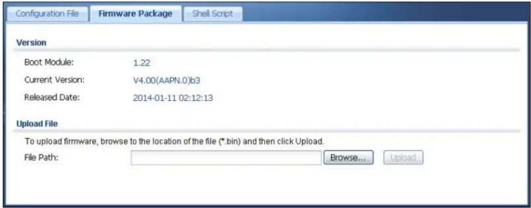
text_image
Configuration File Firmware Package Shell Script Version Boot Module: 1.22 Current Version: V4.00(AAPN.0)b3 Released Date: 2014-01-11 02:12:13 Upload File To upload firmware, browse to the location of the file (*.bin) and then click Upload. File Path: Browse... UploadThe following table describes the labels in this screen.
Table 211 Maintenance > File Manager > Firmware Package
| LABEL DESCRIPTION | |
| Boot Module | This is the version of the boot module that is currently on the UAG. |
| Current Version | This is the firmware version and the date created. |
| Released Date | This is the date that the version of the firmware was created. |
| File Path | Type in the location of the file you want to upload in this field or click Browse ... to find it. |
| Browse... | Click Browse... to find the .bin file you want to upload. Remember that you must decompress compressed (.zip) files before you can upload them. |
| Upload | Click Upload to begin the upload process. This process may take up to two minutes. |
After you see the Firmware Upload in Process screen, wait two minutes before logging into the UAG again.
Figure 314 Firmware Upload In Process
Note: The UAG automatically reboots after a successful upload.
The UAG automatically restarts causing a temporary network disconnect. In some operating systems, you may see the following icon on your desktop.
Figure 315 Network Temporarily Disconnected

text_image
Local Area Connection Network cable unplugged 10:44After five minutes, log in again and check your new firmware version in the Dashboard screen.
If the upload was not successful, the following message appears in the status bar at the bottom of the screen.
Figure 316 Firmware Upload Error

43.4 The Shell Script Screen
Use shell script files to have the UAG use commands that you specify. Use a text editor to create the shell script files. They must use a ".zysh" filename extension.
Click Maintenance > File Manager > Shell Script to open the Shell Script screen. Use the Shell Script screen to store, name, download, upload and run shell script files. You can store multiple shell script files on the UAG at the same time.
Note: You should include write commands in your scripts. If you do not use the write command, the changes will be lost when the UAG restarts. You could use multiple write commands in a long script.
Figure 317 Maintenance > File Manager > Shell Script
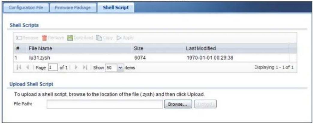
text_image
Configuration File Firmware Package Shell Script Shell Scripts Rename Remove Download Copy ApplyFile Name Size Last Modified
1 lu31.zysh 6074 1970-01-01 00:29:38 Page 1 of 1 Show 50 items Displaying 1 - 1 of 1 Upload Shell Script To upload a shell script, browse to the location of the file (.zysh) and then click Upload. File Path: Browse... UpgradeEach field is described in the following table.
Table 212 Maintenance > File Manager > Shell Script
| LABEL DESCRIPTION | |
| Rename | Use this button to change the label of a shell script file on the UAG.You cannot rename a shell script to the name of another shell script in the UAG.Click a shell script's row to select it and clickRename to open theRename Filescreen.Figure 318 Maintenance > File Manager > Shell Script > Rename Specify the new name for the shell script file. Use up to 25 characters (including a-zA-Z0-9;~!@#%^&()_+[]',=-.ClickOKto save the duplicate or clickCancelto close the screen without saving a duplicate of the configuration file. Specify the new name for the shell script file. Use up to 25 characters (including a-zA-Z0-9;~!@#%^&()_+[]',=-.ClickOKto save the duplicate or clickCancelto close the screen without saving a duplicate of the configuration file. |
| Remove | Click a shell script file's row to select it and clickRemoveto delete the shell script file from the UAG.A pop-up window asks you to confirm that you want to delete the shell script file. ClickOKto delete the shell script file or clickCancelto close the screen without deleting the shell script file. |
| Download | Click a shell script file's row to select it and clickDownloadto save the configuration to your computer. |
| Copy | Use this button to save a duplicate of a shell script file on the UAG.Click a shell script file's row to select it and clickCopyto open theCopy Filescreen.Figure 319 Maintenance > File Manager > Shell Script > Copy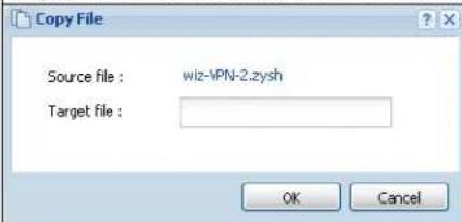 Specify a name for the duplicate file. Use up to 25 characters (including a-zA-Z0-9;~!@#%^&()_+[]{}',=-.ClickOKto save the duplicate or clickCancelto close the screen without saving a duplicate of the configuration file. Specify a name for the duplicate file. Use up to 25 characters (including a-zA-Z0-9;~!@#%^&()_+[]{}',=-.ClickOKto save the duplicate or clickCancelto close the screen without saving a duplicate of the configuration file. |
| Apply | Use this button to have the UAG use a specific shell script file.Click a shell script file's row to select it and clickApplyto have the UAG use that shell script file. You may need to wait awhile for the UAG to finish applying the commands. |
| # | This column displays the number for each shell script file entry. |
| File Name This column displays the label that identifies a shell script file. | |
| Size This column displays the size (in KB) of a shell script file. | |
| Last Modified | This column displays the date and time that the individual shell script files were last changed or saved. |
| Upload Shell Script | The bottom part of the screen allows you to upload a new or previously saved shell script file from your computer to your UAG. |
| File Path | Type in the location of the file you want to upload in this field or clickBrowse...to find it. |
| Browse... | ClickBrowse...to find the .zysh file you want to upload. |
| Upload | ClickUploadto begin the upload process. This process may take up to several minutes. |
44.1 Overview
Use the diagnostics screens for troubleshooting.
44.1.1 What You Can Do in this Chapter
- Use the Diagnostics screen (see Section 44.2 on page 461) to generate a file containing the UAG's configuration and diagnostic information if you need to provide it to customer support during troubleshooting.
- Use the Packet Capture screens (see Section 44.3 on page 463) to capture packets going through the UAG.
- Use the Core Dump screens (see Section 44.4 on page 466) to have the UAG save a process's core dump to an attached USB storage device if the process terminates abnormally (crashes) so you can send the file to customer support for troubleshooting.
- Use the System Log screens (see Section 44.5 on page 467) to download files of system logs from a connected USB storage device to your computer.
44.2 The Diagnostics Screen
The Diagnostic screen provides an easy way for you to generate a file containing the UAG's configuration and diagnostic information. You may need to send this file to customer support for troubleshooting.
Click Maintenance > Diagnostics to open the Diagnostic screen.
Figure 320 Maintenance > Diagnostics

text_image
Diagnostics Packet Capture Core Dump System Log Collect Files Diagnostic Information Collector Filename: diaginfo-19700101.tar.bz2 Last modified: 1970-01-01 08:52:05 Size: 910 KB Copy the diagnostic file to USB storage (if ready) Apply Collect Now DownloadThe following table describes the labels in this screen.
Table 213 Maintenance > Diagnostics
| LABEL DESCRIPTION | |
| Filename This is the name of the most recently created diagnostic file. | |
| Last modified | This is the date and time that the last diagnostic file was created. The format is yyyy-mm-dd hh:mm:ss. |
| Size This is the size of the most recently created diagnostic file. | |
| Copy the diagnostic file to USB storage (if ready) | Select this to have the UAG create an extra copy of the diagnostic file to a connected USB storage device. |
| Apply | Click Apply to save your changes. |
| Collect Now Click this to have the UAG create a new diagnostic file. | |
| Download Click this to save the most recent diagnostic file to a computer. | |
44.2.1 The Diagnostics Files Screen
Click Maintenance > Diagnostics > Files to open the diagnostic files screen. This screen lists the files of diagnostic information the UAG has collected and stored in a connected USB storage device. You may need to send these files to customer support for troubleshooting.
Figure 321 Maintenance > Diagnostics > Files

text_image
Diagnostics Packet Capture Core Dump System Log Collect Files Old archives in USB storage Remove Download # File Name Size Last Modified K Page 1 of 1 Show 50 items No data to displayThe following table describes the labels in this screen.
Table 214 Maintenance > Diagnostics > Files
| LABEL DESCRIPTION | |
| Remove | Select files and click Remove to delete them from the UAG. Use the [Shift] and/or [Ctrl] key to select multiple files. A pop-up window asks you to confirm that you want to delete. |
| Download | Click a file to select it and click Download to save it to your computer. |
| # | This column displays the number for each file entry. The total number of files that you can save depends on the file sizes and the available storage space. |
| File Name This | column displays the label that identifies the file. |
| Size This column | n displays the size (in bytes) of a file. |
| Last Modified | This column displays the date and time that the individual files were saved. |
44.3 The Packet Capture Screen
Use this screen to capture network traffic going through the UAG's interfaces. Studying these packet captures may help you identify network problems. Click Maintenance > Diagnostics > Packet Capture to open the packet capture screen.
Note: New capture files overwrite existing files of the same name. Change the File Suffix field's setting to avoid this.
Figure 322 Maintenance > Diagnostics > Packet Capture

text_image
Diagnostics Packet Capture Core Dump System Log Capture Files Interfaces Available Interfaces wan1 lan1 lan2 Capture Interfaces Filter IP Version: any Protocol Type: icmp Host IP: any Host Port: 0 (0: any) Misc setting ✓ Continuously capture and overwrite old ones ○ Save data to onboard storage only (available: 469 MB) ○ Save data to USB storage (service deactivated) Captured Packet Files: 10 MB Split threshold: 2 MB Duration: 0 (0: unlimited) File Suffix: -packet-capture Number Of Bytes To Capture (Per Packet): 1500 Bytes Capture Stop ResetThe following table describes the labels in this screen.
Table 215 Maintenance > Diagnostics > Packet Capture
| LABEL DESCRIPTION | |
| Interfaces | Enabled interfaces (except for virtual interfaces) appear under Available Interfaces. Select interfaces for which to capture packets and click the right arrow button to move them to the Capture Interfaces list. Use the [Shift] and/or [Ctrl] key to select multiple objects. |
| IP Version | Select the version of the Internet Protocol (IP) by which traffic is routed across the networks and Internet. Select any to capture packets for traffic sent by either IP version. |
| Protocol Type | Select the protocol type of traffic for which to capture packets. Select any to capture packets for all types of traffic. |
| Host IP | Select a host IP address object for which to capture packets. Select any to capture packets for all hosts. Select User Defined to be able to enter an IP address. |
| Host Port | This field is configurable when you set the Protocol Type to any, tcp, or udp. Specify the port number of traffic to capture. |
| Continuously capture and overwrite old ones | Select this to have the UAG keep capturing traffic and overwriting old packet capture entries when the available storage space runs out. |
| Save data to onboard storage only | Select this to have the UAG only store packet capture entries on the UAG. The available storage size is displayed as well.Note: The UAGL reserves some onboard storage space as a buffer. |
| Save data to USB storage | Select this to have the UAG store packet capture entries only on a USB storage device connected to the UAG.Status:Unused - the connected USB storage device was manually unmounted by using the Remove Now button or for some reason the UAG cannot mount it none - no USB storage device is connected.available - you can have the UAG use the USB storage device. The available storage capacity also displays.service deactivated - the USB storage feature is disabled and the UAG cannot use a connected USB device to store the system log and other diagnostic information.Note: The UAG reserves some USB storage space as a buffer. |
| Captured Packet Files | When saving packet captures only to the UAG's onboard storage, specify a maximum limit in megabytes for the total combined size of all the capture files on the UAG.When saving packet captures to a connected USB storage device, specify a maximum limit in megabytes for each capture file.Note: If you have existing capture files and have not selected the Continuously capture and overwrite old ones option, you may need to set this size larger or delete existing capture files.The valid range depends on the available onboard/USB storage size. The UAG stops the capture and generates the capture file when either the file reaches this size or the time period specified in the Duration field expires. |
| Split threshold | Specify a maximum size limit in megabytes for individual packet capture files. After a packet capture file reaches this size, the UAG starts another packet capture file. |
| Duration Set a time limit | in seconds for the capture. The UAG stops the capture and generates the capture file when either this period of time has passed or the file reaches the size specified in the File Size field. 0 means there is no time limit. |
| File Suffix Specify text to | add to the end of the file name (before the dot and filename extension) to help you identify the packet capture files. Modifying the file suffix also avoids making new capture files that overwrite existing files of the same name.The file name format is “interface name-file suffix.cap”, for example “vlan2-packet-capture.cap”. |
| Number Of Bytes To Capture (Per Packet) | Specify the maximum number of bytes to capture per packet. The UAG automatically truncates packets that exceed this size. As a result, when you view the packet capture files in a packet analyzer, the actual size of the packets may be larger than the size of captured packets. |
| Capture Click this button | to have the UAG capture packets according to the settings configured in this screen.You can configure the UAG while a packet capture is in progress although you cannot modify the packet capture settings.The UAG’s throughput or performance may be affected while a packet capture is in progress.After the UAG finishes the capture it saves a separate capture file for each selected interface. The total number of packet capture files that you can save depends on the file sizes and the available flash storage space. Once the flash storage space is full, adding more packet captures will fail. |
| Stop | Click this button to stop a currently running packet capture and generate a separate capture file for each selected interface. |
| Reset Click this button to | return the screen to its last-saved settings. |
44.3.1 The Packet Capture Files Screen
Click Maintenance > Diagnostics > Packet Capture > Files to open the packet capture files screen. This screen lists the files of packet captures stored on the UAG or a connected USB storage device. You can download the files to your computer where you can study them using a packet analyzer (also known as a network or protocol analyzer) such as Wireshark.
Figure 323 Maintenance > Diagnostics > Packet Capture > Files

text_image
Diagnostics Packet Capture Core Dump System Log Capture Files Captured Packet FilesFile Name Size Last Modified
1 dmz-packet-capture.txt 76 2012-04-05 05:38:30 Page 1 of 1 Show 50 items Displaying 1 - 1 of 1 Captured Packet Files in USB storageFile Name Size Last Modified
Page 1 of 1 Show 50 items No data to displayThe following table describes the labels in this screen.
Table 216 Maintenance > Diagnostics > Packet Capture > Files
| LABEL DESCRIPTION | |
| Remove | Select files and click Remove to delete them from the UAG or the connected USB storage device. Use the [Shift] and/or [Ctrl] key to select multiple files. A pop-up window asks you to confirm that you want to delete. |
| Download | Click a file to select it and click Download to save it to your computer. |
| # | This column displays the number for each packet capture file entry. The total number of packet capture files that you can save depends on the file sizes and the available flash storage space. |
| File Name | This column displays the label that identifies the file. The file name format is interface name-file suffix.cap. |
| Size This column | displays the size (in bytes) of a configuration file. |
| Last Modified | This column displays the date and time that the individual files were saved. |
44.4 Core Dump Screen
Use the Core Dump screen to have the UAG save a process's core dump to an attached USB storage device if the process terminates abnormally (crashes). You may need to send this file to customer support for troubleshooting.
Click Maintenance > Diagnostics > Core Dump to open the following screen.
Figure 324 Maintenance > Diagnostics > Core Dump
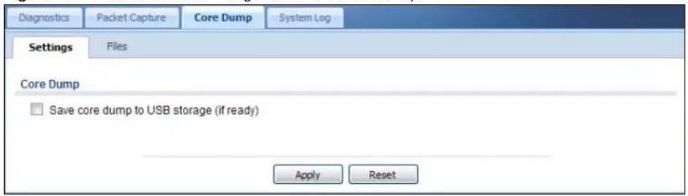
text_image
Diagnostics Packet Capture Core Dump System Log Settings Files Core Dump Save core dump to USB storage (if ready) Apply ResetThe following table describes the labels in this screen.
Table 217 Maintenance > Diagnostics > Core Dump
| LABEL DESCRIPTION | |
| Save core dump to USB storage (if ready) | Select this to have the UAG save a process's core dump to an attached USB storage device if the process terminates abnormally (crashes). If you clear this option the UAG only saves |
| Apply Click Apply to save the changes. | |
| Reset | Click Reset to return the screen to its last-saved settings. |
44.4.1 Core Dump Files Screen
Click Maintenance > Diagnostics > Core Dump > Files to open the core dump files screen. This screen lists the core dump files stored on the UAG or a connected USB storage device. You may need to send these files to customer support for troubleshooting.
Figure 325 Maintenance > Diagnostics > Core Dump > Files
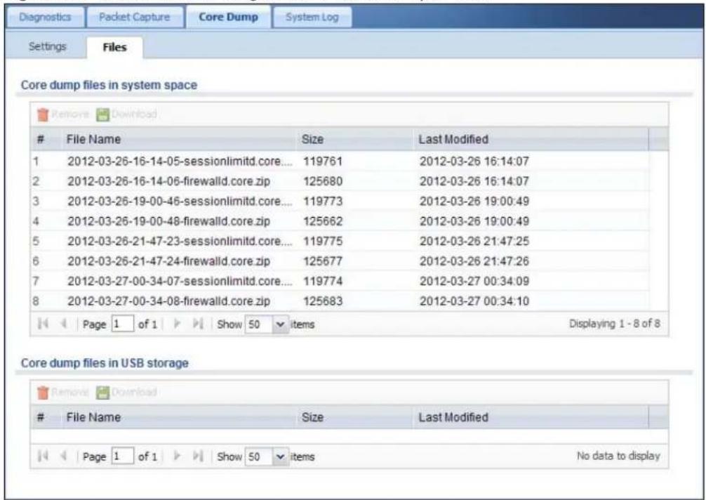
text_image
Core dump files in system spaceFile Name Size Last Modified
1 2012-03-26-16-14-05-sessionlimitd.core.... 119761 2012-03-26 16:14:07 2 2012-03-26-16-14-06-firewalld.core.zip 125680 2012-03-26 16:14:07 3 2012-03-26-19-00-46-sessionlimitd.core.... 119773 2012-03-26 19:00:49 4 2012-03-26-19-00-48-firewalld.core.zip 125662 2012-03-26 19:00:49 5 2012-03-26-21-47-23-sessionlimitd.core.... 119775 2012-03-26 21:47:25 6 2012-03-26-21-47-24-firewalld.core.zip 125677 2012-03-26 21:47:26 7 2012-03-27-00-34-07-sessionlimitd.core.... 119774 2012-03-27 00:34:09 8 2012-03-27-00-34-08-firewalld.core.zip 125683 2012-03-27 00:34:10 Page 1 of 1 Show 50 items Displaying 1 - 8 of 8 Core dump files in USB storageFile Name Size Last Modified
Page 1 of 1 Show 50 items No data to displayThe following table describes the labels in this screen.
Table 218 Maintenance > Diagnostics > Core Dump > Files
| LABEL DESCRIPTION | |
| Remove | Select files and click Remove to delete them from the UAG. Use the [Shift] and/or [Ctrl] key to select multiple files. A pop-up window asks you to confirm that you want to delete. |
| Download | Click a file to select it and click Download to save it to your computer. |
| # | This column displays the number for each packet capture file entry. The total number of packet capture files that you can save depends on the file sizes and the available flash storage space. |
| File Name This column displays the label that identifies the file. | |
| Size This column displays the size (in bytes) of a file. | |
| Last Modified | This column displays the date and time that the individual files were saved. |
44.5 The System Log Screen
Click Maintenance > Diagnostics > System Log to open the system log files screen. This screen lists the files of system logs stored on a connected USB storage device. The files are in comma
separated value (csv) format. You can download them to your computer and open them in a tool like Microsoft's Excel.
Figure 326 Maintenance > Diagnostics > System Log
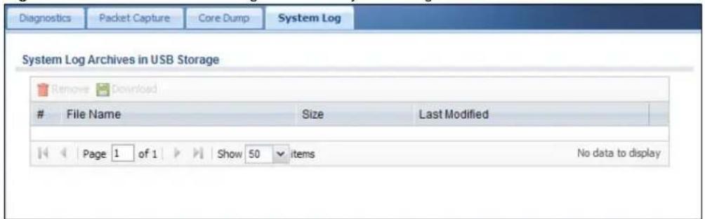
text_image
Diagnostics Packet Capture Core Dump System Log System Log Archives in USB Storage Remove DownloadFile Name Size Last Modified
Page 1 of 1 Show 50 items No data to displayThe following table describes the labels in this screen.
Table 219 Maintenance > Diagnostics > System Log
| LABEL DESCRIPTION | |
| Remove | Select files and click Remove to delete them from the UAG. Use the [Shift] and/or [Ctrl] key to select multiple files. A pop-up window asks you to confirm that you want to delete. |
| Download | Click a file to select it and click Download to save it to your computer. |
| # | This column displays the number for each file entry. The total number of files that you can save depends on the file sizes and the available storage space. |
| File Name This column displays the label that identifies the file. | |
| Size This column displays the size (in bytes) of a file. | |
| Last Modified | This column displays the date and time that the individual files were saved. |
Packet Flow Explore
45.1 Overview
Use this to get a clear picture on how the UAG determines where to forward a packet and how to change the source IP address of the packet according to your current settings. This function provides you a summary of all your routing and SNAT settings and helps troubleshoot any related problems.
45.1.1 What You Can Do in this Chapter
- Use the Routing Status screen (see Section 45.2 on page 469) to view the overall routing flow and each routing function's settings.
- Use the SNAT Status screen (see Section 45.3 on page 474) to view the overall source IP address conversion (SNAT) flow and each SNAT function's settings.
45.2 The Routing Status Screen
The Routing Status screen allows you to view the current routing flow and quickly link to specific routing settings. Click a function box in the Routing Flow section, the related routes (activated) will display in the Routing Table section. To access this screen, click Maintenance > Packet Flow Explore.
The order of the routing flow may vary depending on whether you:
- select use policy route to override direct route in the CONFIGURATION > Network > Routing > Policy Route screen.
- use policy routes to control 1-1 NAT by using the policy control-virtual-server-rules activate command.
- select use policy routes to control dynamic IPSec rules in the CONFIGURATION > VPN > IPSec VPN > VPN Connection screen.
Note: Once a packet matches the criteria of a routing rule, the UAG takes the corresponding action and does not perform any further flow checking.
Figure 327 Maintenance > Packet Flow Explore > Routing Status (Direct Route)

flowchart
graph LR
    A["In"] --> B["Direct Route"]
    B --> C["Dynamic VPN"]
    C --> D["Policy Route"]
    D --> E["VPN 1.1 Mapping Route"]
    E --> F["1.1 SNAT"]
    F --> G["SiteToSite VPN"]
    G --> H["Static Route"]
    H --> I["Default WAN Trunk"]
    I --> J["Main Route"]
    J --> K["Out"]

    subgraph Routing Table
        L["# Destination Gateway Interface Metric Flags Persist"]
        M["1 127.0.0.0/8 0.0.0.0 l0 0 ACG -"]
        N["2 172.16.0.0/16 0.0.0.0 alan1 0 ACG -"]
        O["3 172.17.0.0/16 0.0.0.0 alan2 0 ACG -"]
        P["4 172.18.0.0/16 0.0.0.0 a.mz 0 ACG -"]
    end
Figure 328 Maintenance > Packet Flow Explore > Routing Status (Dynamic VPN)
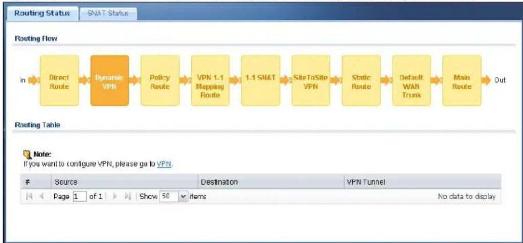
flowchart
graph LR
    A["Direct Route"] --> B["Dynamic VPN"]
    B --> C["Policy Route"]
    C --> D["VPN 1.1 Mapping Route"]
    D --> E["1.1 SNAT"]
    E --> F["SiteToSite VPN"]
    F --> G["Static Route"]
    G --> H["Default WAN Trunk"]
    H --> I["Main Route"]
    I --> J["Out"]
Figure 329 Maintenance > Packet Flow Explore > Routing Status (Policy Route)
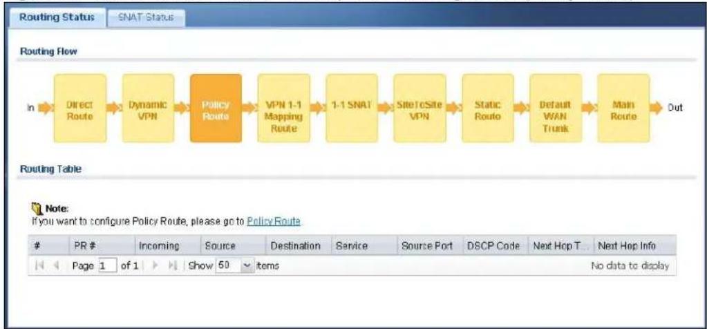
flowchart
graph LR
    A["Direct Route"] --> B["Dynamic VPN"]
    B --> C["Policy Route"]
    C --> D["VPN 1-1 Mapping Route"]
    D --> E["1-1 SNAT"]
    E --> F["SiteToSite VPN"]
    F --> G["Static Route"]
    G --> H["Default WAN Trunk"]
    H --> I["Main Route"]
    I --> J["Out"]
Figure 330 Maintenance > Packet Flow Explore > Routing Status (VPN 1-1 Mapping Route)

flowchart
graph LR
    A["Direct Route"] --> B["Dynamic VPN"]
    B --> C["Policy Route"]
    C --> D["VPN 1.1 Mapping Route"]
    D --> E["1.1 SNAT"]
    E --> F["SiteToSito VPN"]
    F --> G["Static Route"]
    G --> H["Default WAN Trunk"]
    H --> I["Main Route"]
    I --> J["Out"]
Figure 331 Maintenance > Packet Flow Explore > Routing Status (1-1 SNAT)

flowchart
graph LR
    A["Direct Route"] --> B["Dynamic VPN"]
    B --> C["Policy Route"]
    C --> D["VPN 1-1 Mapping Route"]
    D --> E["1-1 SNAT"]
    E --> F["SiteToSite VPN"]
    F --> G["Static Route"]
    G --> H["Default WAN Trunk"]
    H --> I["Main Route"]
    I --> J["Out"]
Figure 332 Maintenance > Packet Flow Explore > Routing Status (SiteToSite VPN)
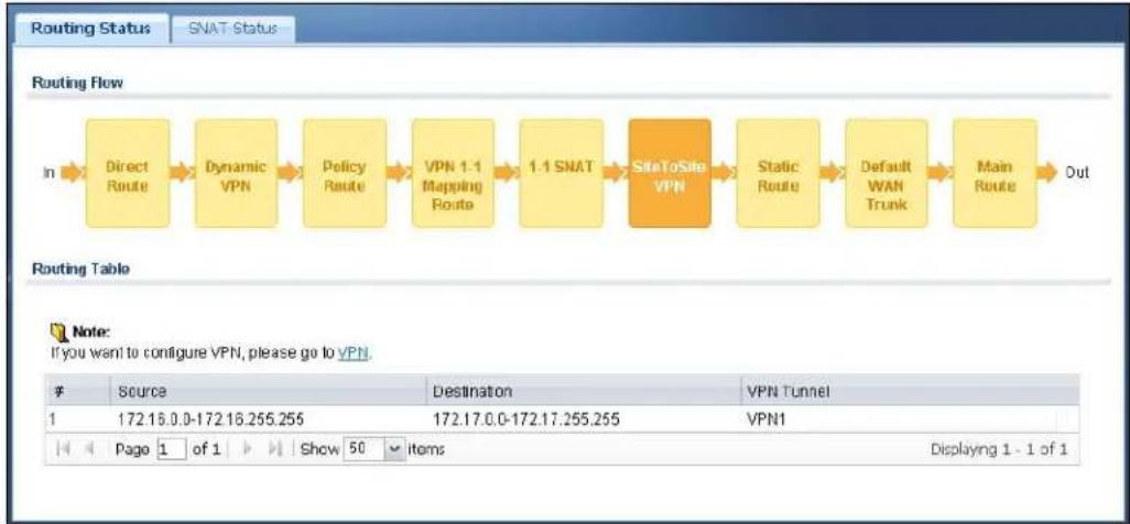
flowchart
graph LR
    A["In"] --> B["Direct Route"]
    B --> C["Dynamic VPN"]
    C --> D["Policy Route"]
    D --> E["VPN 1.1 Mapping Route"]
    E --> F["1.1 SNAT"]
    F --> G["SiteToSite VPN"]
    G --> H["Static Route"]
    H --> I["Default WAN Trunk"]
    I --> J["Main Route"]
    J --> K["Out"]
Figure 333 Maintenance > Packet Flow Explore > Routing Status (Static Route)
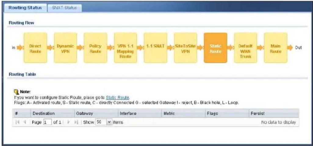
flowchart
graph LR
    A["In"] --> B["Direct Route"]
    B --> C["Dynamic VPN"]
    C --> D["Policy Route"]
    D --> E["VPN 1.1 Mapping Route"]
    E --> F["1.1 SNAT"]
    F --> G["SiteToSite VPN"]
    G --> H["Static Route"]
    H --> I["Default WAN Trunk"]
    I --> J["Main Route"]
    J --> K["Out"]
Figure 334 Maintenance > Packet Flow Explore > Routing Status (Default WAN Trunk)
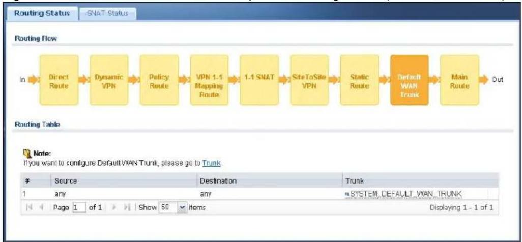
flowchart
graph LR
    A["In"] --> B["Direct Route"]
    B --> C["Dynamic VPN"]
    C --> D["Policy Route"]
    D --> E["VPN 1.1 Mapping Route"]
    E --> F["1.1 SNAT"]
    F --> G["SiteToSite VPN"]
    G --> H["Static Route"]
    H --> I["Default WAN Trunk"]
    I --> J["Main Route"]
    J --> K["Out"]
Figure 335 Maintenance > Packet Flow Explore > Routing Status (Main Route)
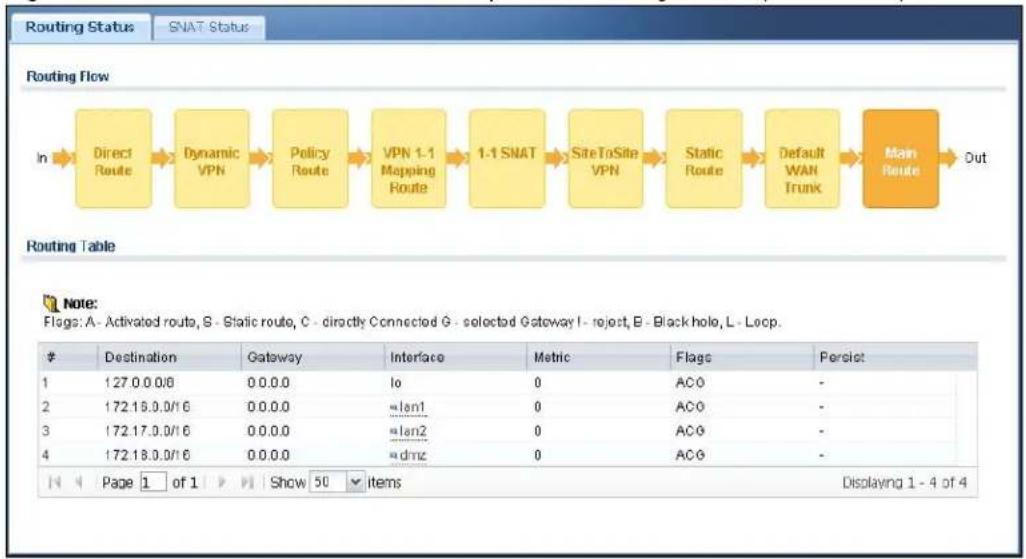
flowchart
graph LR
    A["In"] --> B["Direct Route"]
    B --> C["Dynamic VPN"]
    C --> D["Policy Route"]
    D --> E["VPN 1.1 Mapping Route"]
    E --> F["1.1 SNAT"]
    F --> G["SiteToSite VPN"]
    G --> H["Static Route"]
    H --> I["Default WAN Trunk"]
    I --> J["Main Route"]
    J --> K["Out"]

    subgraph Routing Table
        L["# Destination Gateway Interface Metric Flags Persist"]
        M["1:27.0.0/8 0.0.0 Io 0 ACO -"]
        N["2:172.15.0/16 0.0.0 =lan1 0 ACO -"]
        O["3:172.17.0/16 0.0.0 =lan2 0 ACG -"]
        P["4:172.18.0/16 0.0.0 =dmz 0 ACG -"]
    end
The following table describes the labels in this screen.
Table 220 Maintenance > Packet Flow Explore > Routing Status
| LABEL DESCRIPTION | |
| Routing Flow | This section shows you the flow of how the UAG determines where to route a packet. Click a function box to display the related settings in the Routing Table section. |
| Routing Table | This section shows the corresponding settings according to the function box you click in the Routing Flow section. |
| The following fields are available if you click Direct Route, Static Route, or Main Route in the Routing Flow section. | |
| # | This field is a sequential value, and it is not associated with any entry. |
| Destination This is the destination IP address of a route. | |
| Gateway | This is the IP address of the next-hop gateway or the interface through which the traffic is routed. |
| Interface | This is the name of an interface associated with the route. |
| Metric | This is the route's priority among the displayed routes. |
| Flags | This indicates additional information for the route. The possible flags are:• A - this route is currently activated.• S - this is a static route.• C - this is a direct connected route.• G - the route is to a gateway (router) in the same network.• ! - this is a route which forces a route lookup to fail.• B - this is a route which discards packets.• L - this is a recursive route. |
| Persist | This is the remaining time of a dynamically learned route. The UAG removes the route after this time period is counted down to zero. |
| The following fields are available if you click Dynamic VPN or SiteToSite VPN in the Routing Flow section. | |
| # | This field is a sequential value, and it is not associated with any entry. |
| Source This is the IP address(es) of the local VPN network. | |
| Destination | This is the IP address(es) for the remote VPN network. |
| VPN Tunnel | This is the name of the VPN tunnel. |
| The following fields are available if you click Policy Route in the Routing Flow section. | |
| # | This field is a sequential value, and it is not associated with any entry. |
| PR # | This is the number of an activated policy route. If you have configured a schedule for the route, this screen only displays the route at the scheduled time. |
| Incoming | This is the interface on which the packets are received. |
| Source This is the source IP address(es) from which the packets are sent. | |
| Destination This is the destination IP address(es) to which the packets are transmitted. | |
| Service | This is the name of the service object. any means all services. |
| Source Port | This is the name of a service object. The UAG applies the policy route to the packets sent from the corresponding service port. any means all service ports. |
| DSCP Code | This is the DSCP value of incoming packets to which this policy route applies. See Section 12.2 on page 168 for more information. |
| Next Hop Type | This is the type of the next hop to which packets are directed. |
| Next Hop Info | • This is the main route if the next hop type is Auto.• This is the interface name and gateway IP address if the next hop type is Interface / GW.• This is the trunk name if the next hop type is Trunk. |
| The following fields are available if you click VPN 1-1 Mapping Route in the Routing Flow section. | |
| # | This field is a sequential value, and it is not associated with any entry. |
| Source | This is the original source IP address(es).anymeans any IP address. |
| Destination | This is the original destination IP address(es).anymeans any IP address. |
| Outgoing This is | the name of an interface which transmits packets out of the UAG. |
| Gateway This is | the IP address of the gateway in the same network of the outgoing interface. |
| The following fields are available if you click 1-1 SNAT in theRouting Flowsection. | |
| # | This field is a sequential value, and it is not associated with any entry. |
| NAT Rule | This is the name of an activated 1:1 or Many 1:1 NAT rule in the NAT table. |
| Source | This is the original source IP address(es).anymeans any IP address. |
| Destination | This is the original destination IP address(es).anymeans any IP address. |
| Outgoing This is | the name of an interface which transmits packets out of the UAG. |
| Gateway This is | the IP address of the gateway in the same network of the outgoing interface. |
| The following fields are available if you clickDefault WAN Trunkin theRouting Flowsection. | |
| # | This field is a sequential value, and it is not associated with any entry. |
| Source | This is the source IP address(es) from which the packets are sent.anymeans any IP address. |
| Destination | This is the destination IP address(es) to which the packets are transmitted.anymeans any IP address. |
| Trunk This is the | name of the WAN trunk through which the matched packets are transmitted. |
45.3 The SNAT Status Screen
The SNAT Status screen allows you to view and quickly link to specific source NAT (SNAT) settings. Click a function box in the SNAT Flow section, the related SNAT rules (activated) will display in the SNAT Table section. To access this screen, click Maintenance > Packet Flow Explore > SNAT Status.
The order of the SNAT flow may vary depending on whether you:
- select use default SNAT in the Configuration > Network > Interface > Trunk screen.
- use policy routes to control 1-1 NAT by using the policy control-virtual-server-rules activate command.
Note: Once a packet matches the criteria of an SNAT rule, the UAG takes the corresponding action and does not perform any further flow checking.
Figure 336 Maintenance > Packet Flow Explore > SNAT Status (Policy Route SNAT)
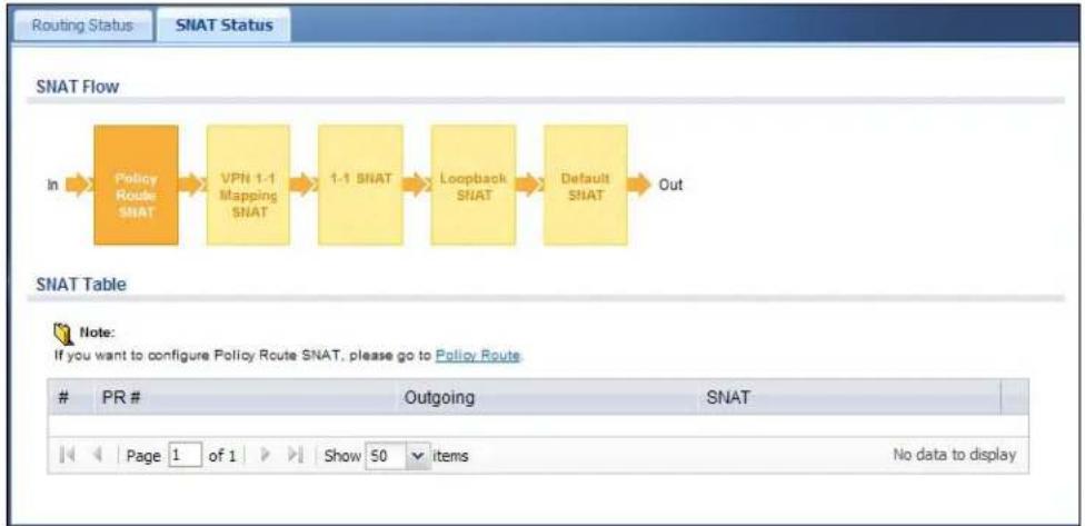
flowchart
graph LR
    A["In"] --> B["Policy Route SNAT"]
    B --> C["VPN 1-1 Mapping SNAT"]
    C --> D["1-1 SNAT"]
    D --> E["Loopback SNAT"]
    E --> F["Default SNAT"]
    F --> G["Out"]
Figure 337 Maintenance > Packet Flow Explore > SNAT Status (VPN 1-1 Mapping Route)
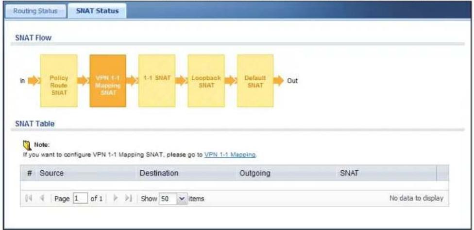
flowchart
graph LR
    A["In"] --> B["Policy Route SNAT"]
    B --> C["VPN 1-1 Mapping SNAT"]
    C --> D["1-1 SNAT"]
    D --> E["Loopback SNAT"]
    E --> F["Default SNAT"]
    F --> G["Out"]
Figure 338 Maintenance > Packet Flow Explore > SNAT Status (1-1 SNAT)

flowchart
graph LR
    A["Policy Route SNAT"] --> B["VPN 1-1 Mapping SNAT"]
    B --> C["1-1 SNAT"]
    C --> D["Loopback SNAT"]
    D --> E["Default SNAT"]
    E --> F["Out"]
Figure 339 Maintenance > Packet Flow Explore > SNAT Status (Loopback SNAT)

flowchart
graph LR
    A["Policy Route SNAT"] --> B["VPN 1-1 Mapping SNAT"]
    B --> C["1-1 SNAT"]
    C --> D["Loopback SNAT"]
    D --> E["Default SNAT"]
    E --> F["Out"]
Figure 340 Maintenance > Packet Flow Explore > SNAT Status (Default SNAT)

flowchart
graph LR
    A["Policy Route SNAT"] --> B["VPN 1-1 Mapping SNAT"]
    B --> C["1-1 SNAT"]
    C --> D["Loopback SNAT"]
    D --> E["Default SNAT"]
    E --> F["Out"]
The following table describes the labels in this screen.
Table 221 Maintenance > Packet Flow Explore > SNAT Status
| LABEL DESCRIPTION | |
| SNAT Flow | This section shows you the flow of how the UAG changes the source IP address for a packet according to the rules you have configured in the UAG. Click a function box to display the related settings in the SNAT Table section. |
| SNAT Table | The table fields in this section vary depending on the function box you select in the SNAT Flow section. |
| The following fields are available if you click Policy Route SNAT in the SNAT Flow section. | |
| # | This field is a sequential value, and it is not associated with any entry. |
| PR # This is the | number of an activated policy route which uses SNAT. |
| Outgoing | This is the outgoing interface that the route uses to transmit packets. |
| SNAT | This is the source IP address(es) that the SNAT rule uses finally. |
| The following fields are available if you click VPN 1-1 Mapping SNAT in the SNAT Flow section. | |
| # | This field is a sequential value, and it is not associated with any entry. |
| Source This is the original source IP address(es). | |
| Destination This is the original destination IP address(es). | |
| Outgoing | This is the outgoing interface that the SNAT rule uses to transmit packets. |
| SNAT This is the source IP address(es) that the SNAT rule uses finally. | |
| The following fields are available if you click 1-1 SNAT in the SNAT Flow section. | |
| # | This field is a sequential value, and it is not associated with any entry. |
| NAT Rule | This is the name of an activated NAT rule which uses SNAT. |
| Source This is the original source IP address(es). | |
| Destination This is the original destination IP address(es). | |
| Outgoing | This is the outgoing interface that the SNAT rule uses to transmit packets. |
| SNAT This is the source IP address(es) that the SNAT rule uses finally. | |
| The following fields are available if you click Loopback SNAT in the SNAT Flow section. | |
| # | This field is a sequential value, and it is not associated with any entry. |
| NAT Rule | This is the name of an activated NAT rule which uses SNAT and enables NAT loopback. |
| Source | This is the original source IP address(es). any means any IP address. |
| Destination | This is the original destination IP address(es). any means any IP address. |
| SNAT | This indicates which source IP address the SNAT rule uses finally. For example,Outgoing Interface IP means that the UAG uses the IP address of the outgoing interface as the source IP address for the matched packets it sends out through this rule. |
| The following fields are available if you click Default SNAT in the SNAT Flow section. | |
| # | This field is a sequential value, and it is not associated with any entry. |
| Incoming This indicates internal interface(s) on which the packets are received. | |
| Outgoing | This indicates external interface(s) from which the packets are transmitted. |
| SNAT | This indicates which source IP address the SNAT rule uses finally. For example,Outgoing Interface IP means that the UAG uses the IP address of the outgoing interface as the source IP address for the matched packets it sends out through this rule. |
46.1 Overview
Use this to restart the device (for example, if the device begins behaving erratically). See also Section 1.5 on page 31 for information on different ways to start and stop the UAG.
46.1.1 What You Need To Know
If you applied changes in the Web configurator, these were saved automatically and do not change when you reboot. If you made changes in the CLI, however, you have to use the write command to save the configuration before you reboot. Otherwise, the changes are lost when you reboot.
Reboot is different to reset; (see Section 48.1 on page 487) reset returns the device to its default configuration.
46.2 The Reboot Screen
The Reboot screen allows remote users to restart the device. To access this screen, click Maintenance > Reboot.
Figure 341 Maintenance > Reboot

text_image
Reboot Reboot Click the Reboot button to reboot the device. Please wait a few minutes until the login screen appears. If the login screen does not appear, type the IP address of the device in your Web browser. RebootClick the Reboot button to restart the UAG. Wait a few minutes until the login screen appears. If the login screen does not appear, type the IP address of the device in your Web browser.
You can also use the CLI command reboot to restart the UAG.
Shutdown
47.1 Overview
Use this to shutdown the device in preparation for disconnecting the power. See also Section 1.5 on page 31 for information on different ways to start and stop the UAG.
Always use the Maintenance > Shutdown > Shutdown screen or the "shutdown" command before you turn off the UAG or remove the power. Not doing so can cause the firmware to become corrupt.
47.1.1 What You Need To Know
Shutdown writes all cached data to the local storage and stops the system processes.
47.2 The Shutdown Screen
To access this screen, click Maintenance > Shutdown.
Figure 342 Maintenance > Shutdown
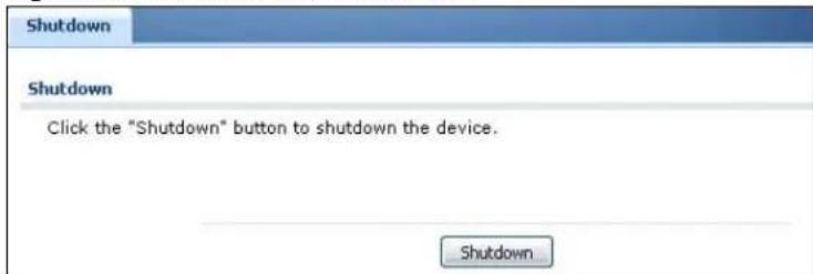
text_image
Shutdown Shutdown Click the "Shutdown" button to shutdown the device. ShutdownClick the Shutdown button to shut down the UAG. Wait for the device to shut down before you manually turn off or remove the power. It does not turn off the power.
You can also use the CLI command shutdown to shutdown the UAG.
Troubleshooting
This chapter offers some suggestions to solve problems you might encounter.
- You can also refer to the logs (see Chapter 7 on page 104).
- For the order in which the UAG applies its features and checks, see Chapter 45 on page 469.
None of the LEDs turn on.
Make sure that you have the power cord connected to the UAG and plugged in to an appropriate power source. Make sure you have the UAG turned on. Check all cable connections.
If the LEDs still do not turn on, you may have a hardware problem. In this case, you should contact your local vendor.
Cannot access the UAG from the LAN.
- Check the cable connection between the UAG and your computer or switch.
- Ping the UAG from a LAN computer. Make sure your computer's Ethernet card is installed and functioning properly. Also make sure that its IP address is in the same subnet as the UAG's.
- In the computer, click Start, (All) Programs, Accessories and then Command Prompt. In the Command Prompt window, type "ping" followed by the UAG's LAN IP address (172.16.0.1 or 172.17.0.1 is the default) and then press [ENTER]. The UAG should reply.
- If you've forgotten the UAG's password, use the RESET button. Press the button in for about 5 seconds (or until the PWR LED starts to blink), then release it. It returns the UAG to the factory defaults (password is 1234, LAN IP address 172.16.0.1 or 172.17.0.1 etc.; see your User's Guide for details).
- If you've forgotten the UAG's IP address, you can use the commands through the console port to check it. Connect your computer to the CONSOLE port using a console cable. Your computer should have a terminal emulation communications program (such as HyperTerminal) set to VT100 terminal emulation, no parity, 8 data bits, 1 stop bit, no flow control and 115200 bps port speed.
I cannot access the Internet.
- Check the UAG's connection to the Ethernet jack with Internet access. Make sure the Internet gateway device (such as a DSL modem) is working properly.
- Check the WAN interface's status in the Dashboard. Use the installation setup wizard again and make sure that you enter the correct settings. Use the same case as provided by your ISP.
I configured security settings but the UAG is not applying them for certain interfaces.
Many security settings are usually applied to zones. Make sure you assign the interfaces to the appropriate zones. When you create an interface, there is no security applied on it until you assign it to a zone.
The UAG is not applying the custom policy route I configured.
The UAG checks the policy routes in the order that they are listed. So make sure that your custom policy route comes before any other routes that the traffic would also match.
The UAG is not applying the custom firewall rule I configured.
The UAG checks the firewall rules in the order that they are listed. So make sure that your custom firewall rule comes before any other rules that the traffic would also match.
I cannot enter the interface name I want.
- The format of interface names other than the Ethernet interface names is very strict. Each name consists of 2-4 letters (interface type), followed by a number (x, limited by the maximum number of each type of interface). For example, VLAN interfaces are vlan0, vlan1, vlan2, ...; and so on.
- The names of virtual interfaces are derived from the interfaces on which they are created. For example, virtual interfaces created on Ethernet interface wan1 are called wan1:1, wan1:2, and so on. Virtual interfaces created on VLAN interface vlan2 are called vlan2:1, vlan2:2, and so on. You cannot specify the number after the colon(:) in the Web Configurator; it is a sequential number. You can specify the number after the colon if you use the CLI to set up a virtual interface.
I cannot set up a PPP interface, virtual Ethernet interface or virtual VLAN interface on an Ethernet interface.
You cannot set up a PPP interface, virtual Ethernet interface or virtual VLAN interface if the underlying interface is a member of a bridge. You also cannot add an Ethernet interface or VLAN interface to a bridge if the member interface has a virtual interface or PPP interface on top of it.
My rules and settings that apply to a particular interface no longer work.
The interface's IP address may have changed. To avoid this create an IP address object based on the interface. This way the UAG automatically updates every rule or setting that uses the object whenever the interface's IP address settings change. For example, if you change LAN1's IP address, the UAG automatically updates the corresponding interface-based, LAN1 subnet address object.
I cannot set up a PPP interface.
You have to set up an ISP account before you create a PPPoE or PPTP interface.
I cannot configure a particular VLAN interface on top of an Ethernet interface even though I have it configured it on top of another Ethernet interface.
Each VLAN interface is created on top of only one Ethernet interface.
The UAG is not applying an interface's configured ingress bandwidth limit.
At the time of writing, the UAG does not support ingress bandwidth management.
The UAG routes and applies SNAT for traffic from some interfaces but not from others.
The UAG automatically uses SNAT for traffic it routes from internal interfaces to external interfaces. For example LAN to WAN traffic. You must manually configure a policy route to add routing and SNAT settings for an interface with the Interface Type set to General. You can also configure a policy route to override the default routing and SNAT behavior for an interface with the Interface Type set to Internal or External.
I cannot get Dynamic DNS to work.
- You must have a public WAN IP address to use Dynamic DNS.
- Make sure you recorded your DDNS account's user name, password, and domain name and have entered them properly in the UAG.
- You may need to configure the DDNS entry's IP Address setting to Auto if the interface has a dynamic IP address or there are one or more NAT routers between the UAG and the DDNS server.
- The UAG may not determine the proper IP address if there is an HTTP proxy server between the UAG and the DDNS server.
I cannot create a second HTTP redirect rule for an incoming interface.
You can configure up to one HTTP redirect rule for each (incoming) interface.
The UAG keeps resetting the connection.
If an alternate gateway on the LAN has an IP address in the same subnet as the UAG's LAN IP address, return traffic may not go through the UAG. This is called an asymmetrical or "triangle" route. This causes the UAG to reset the connection, as the connection has not been acknowledged.
You can set the UAG's firewall to permit the use of asymmetrical route topology on the network (so it does not reset the connection) although this is not recommended since allowing asymmetrical routes may let traffic from the WAN go directly to the LAN without passing through the UAG. A better solution is to use virtual interfaces to put the UAG and the backup gateway on separate subnets. See Asymmetrical Routes on page 247 and the chapter about interfaces for more information.
I cannot set up an IPSec VPN tunnel to another device.
If the IPSec tunnel does not build properly, the problem is likely a configuration error at one of the IPSec routers. Log into both ZyXEL IPSec routers and check the settings in each field methodically and slowly. Make sure both the UAG and remote IPSec router have the same security settings for the VPN tunnel. It may help to display the settings for both routers side-by-side.
Here are some general suggestions. See also Chapter 22 on page 253.
- The system log can often help to identify a configuration problem.
- If you enable NAT traversal, the remote IPSec device must also have NAT traversal enabled.
- The UAG and remote IPSec router must use the same authentication method to establish the IKE SA.
- Both routers must use the same negotiation mode.
- Both routers must use the same encryption algorithm, authentication algorithm, and DH key group.
- When using pre-shared keys, the UAG and the remote IPSec router must use the same pre-shared key.
- The UAG's local and peer ID type and content must match the remote IPSec router's peer and local ID type and content, respectively.
- The UAG and remote IPSec router must use the same active protocol.
-
The UAG and remote IPSec router must use the same encapsulation.
-
If the sites are/were previously connected using a leased line or ISDN router, physically disconnect these devices from the network before testing your new VPN connection. The old route may have been learnt by RIP and would take priority over the new VPN connection.
- To test whether or not a tunnel is working, ping from a computer at one site to a computer at the other. Before doing so, ensure that both computers have Internet access (via the IPSec routers).
- It is also helpful to have a way to look at the packets that are being sent and received by the UAG and remote IPSec router (for example, by using a packet sniffer).
Check the configuration for the following UAG features.
- The UAG does not put IPSec SAs in the routing table. You must create a policy route for each VPN tunnel. See Chapter 10 on page 153.
- Make sure the To-Device firewall rules allow IPSec VPN traffic to the UAG. IKE uses UDP port 500, AH uses IP protocol 51, and ESP uses IP protocol 50.
- The UAG supports UDP port 500 and UDP port 4500 for NAT traversal. If you enable this, make sure the To-Device firewall rules allow UDP port 4500 too.
- Make sure regular firewall rules allow traffic between the VPN tunnel and the rest of the network. Regular firewall rules check packets the UAG sends before the UAG encrypts them and check packets the UAG receives after the UAG decrypts them. This depends on the zone to which you assign the VPN tunnel and the zone from which and to which traffic may be routed.
- If you set up a VPN tunnel across the Internet, make sure your ISP supports AH or ESP (whichever you are using).
- If you have the UAG and remote IPSec router use certificates to authenticate each other, You must set up the certificates for the UAG and remote IPSec router first and make sure they trust each other's certificates. If the UAG's certificate is self-signed, import it into the remote IPSec router. If it is signed by a CA, make sure the remote IPSec router trusts that CA. The UAG uses one of its Trusted Certificates to authenticate the remote IPSec router's certificate. The trusted certificate can be the remote IPSec router's self-signed certificate or that of a trusted CA that signed the remote IPSec router's certificate.
- Multiple SAs connecting through a secure gateway must have the same negotiation mode.
The VPN connection is up but VPN traffic cannot be transmitted through the VPN tunnel.
If you have the Configuration > VPN > IPSec VPN > VPN Connection screen's Use Policy Route to control dynamic IPSec rules option enabled, check the routing policies to see if they are sending traffic elsewhere instead of through the VPN tunnels.
I changed the LAN IP address and can no longer access the Internet.
The UAG automatically updates address objects based on an interface's IP address, subnet, or gateway if the interface's IP address settings change. However, you need to manually edit any address objects for your LAN that are not based on the interface.
I cannot get the RADIUS server to authenticate the UAG's default admin account.
The default admin account is always authenticated locally, regardless of the authentication method setting. (See Chapter 37 on page 368 for more information about authentication methods.)
The UAG fails to authentication the ext-user user accounts I configured.
An external server such as RADIUS must authenticate the ext-user accounts. If the UAG tries to use the local database to authenticate an ext-user, the authentication attempt will always fail. (This is related to AAA servers and authentication methods, which are discussed in Chapter 37 on page 368 and Chapter 38 on page 372, respectively.)
I cannot add the admin users to a user group with access users.
You cannot put access users and admin users in the same user group.
I cannot add the default admin account to a user group.
You cannot put the default admin account into any user group.
The schedule I configured is not being applied at the configured times.
Make sure the UAG's current date and time are correct.
I cannot get a certificate to import into the UAG.
1 For My Certificates, you can import a certificate that matches a corresponding certification request that was generated by the UAG. You can also import a certificate in PKCS# 12 format, including the certificate's public and private keys.
2 You must remove any spaces from the certificate's filename before you can import the certificate.
3 Any certificate that you want to import has to be in one of these file formats:
- Binary X.509: This is an ITU-T recommendation that defines the formats for X.509 certificates.
- PEM (Base-64) encoded X.509: This Privacy Enhanced Mail format uses lowercase letters, uppercase letters and numerals to convert a binary X.509 certificate into a printable form.
- Binary PKCS#7: This is a standard that defines the general syntax for data (including digital signatures) that may be encrypted. A PKCS #7 file is used to transfer a public key certificate. The private key is not included. The UAG currently allows the importation of a PKS#7 file that contains a single certificate.
- PEM (Base-64) encoded PKCS#7: This Privacy Enhanced Mail (PEM) format uses lowercase letters, uppercase letters and numerals to convert a binary PKCS#7 certificate into a printable form.
- Binary PKCS# 12: This is a format for transferring public key and private key certificates. The private key in a PKCS # 12 file is within a password-encrypted envelope. The file's password is not connected to your certificate's public or private passwords. Exporting a PKCS # 12 file creates this and you must provide it to decrypt the contents when you import the file into the UAG.
Note: Be careful not to convert a binary file to text during the transfer process. It is easy for this to occur since many programs use text files by default.
I cannot access the UAG from a computer connected to the Internet.
Check the service control rules and to-UAG firewall rules.
I uploaded a logo to display on the upper left corner of the Web Configurator login screen and access page but it does not display properly.
Make sure the logo file is a GIF, JPG, or PNG of 100 kilobytes or less.
I uploaded a logo to use as the screen or window background but it does not display properly.
Make sure the logo file is a GIF, JPG, or PNG of 100 kilobytes or less.
The UAG's traffic throughput rate decreased after I started collecting traffic statistics.
Data collection may decrease the UAG's traffic throughput rate.
I can only see newer logs. Older logs are missing.
When a log reaches the maximum number of log messages, new log messages automatically overwrite existing log messages, starting with the oldest existing log message first.
The commands in my configuration file or shell script are not working properly.
- In a configuration file or shell script, use “#” or “!” as the first character of a command line to have the UAG treat the line as a comment.
- Your configuration files or shell scripts can use "exit" or a command line consisting of a single "!" to have the UAG exit sub command mode.
- Include write commands in your scripts. Otherwise the changes will be lost when the UAG restarts. You could use multiple write commands in a long script.
Note: “exit” or “!” must follow sub commands if it is to make the UAG exit sub command mode.
See Chapter 43 on page 450 for more on configuration files and shell scripts.
I cannot get the firmware uploaded using the commands.
The Web Configurator is the recommended method for uploading firmware. You only need to use the command line interface if you need to recover the firmware. See the CLI Reference Guide for how to determine if you need to recover the firmware and how to recover it.
My packet capture captured less than I wanted or failed.
The packet capture screen's File Size sets a maximum size limit for the total combined size of all the capture files on the UAG, including any existing capture files and any new capture files you generate. If you have existing capture files you may need to set this size larger or delete existing capture files.
The UAG stops the capture and generates the capture file when either the capture files reach the File Size or the time period specified in the Duration field expires.
My earlier packet capture files are missing.
New capture files overwrite existing files of the same name. Change the File Suffix field's setting to avoid this.
48.1 Resetting the UAG
If you cannot access the UAG by any method, try restarting it by turning the power off and then on again. If you still cannot access the UAG by any method or you forget the administrator
password(s), you can reset the UAG to its factory-default settings. Any configuration files or shell scripts that you saved on the UAG should still be available afterwards.
Use the following procedure to reset the UAG to its factory-default settings. This overwrites the settings in the startup-config.conf file with the settings in the system-default.conf file.
Note: This procedure removes the current configuration.
If you want to reboot the device without changing the current configuration, see Chapter 46 on page 478.
1 Make sure the SYS LED is on and not blinking.
2 Press the RESET button and hold it until the SYS LED begins to blink. (This usually takes about five seconds.)
3 Release the RESET button, and wait for the UAG to restart.
You should be able to access the UAG using the default settings.
48.2 Getting More Troubleshooting Help
Search for support information for your model at www.zyxel.com for more troubleshooting suggestions.
Legal Information
Copyright
Copyright © 2014 by ZyXEL Communications Corporation.
The contents of this publication may not be reproduced in any part or as a whole, transcribed, stored in a retrieval system, translated into any language, or transmitted in any form or by any means, electronic, mechanical, magnetic, optical, chemical, photocopying, manual, or otherwise, without the prior written permission of ZyXEL Communications Corporation.
Published by ZyXEL Communications Corporation. All rights reserved.
Disclaimer
ZyXEL does not assume any liability arising out of the application or use of any products, or software described herein. Neither does it convey any license under its patent rights nor the patent rights of others. ZyXEL further reserves the right to make changes in any products described herein without notice. This publication is subject to change without notice.
Certifications
Federal Communications Commission (FCC) Interference Statement
This device complies with Part 15 of FCC rules. Operation is subject to the following two conditions:
This device may not cause harmful interference.
This device must accept any interference received, including interference that may cause undesired operations.
FCC Warning
This device has been tested and found to comply with the limits for a Class A digital switch, pursuant to Part 15 of the FCC Rules. These limits are designed to provide reasonable protection against harmful interference in a commercial environment. This device generates, uses, and can radiate radio frequency energy and, if not installed and used in accordance with the instruction manual, may cause harmful interference to radio communications. Operation of this device in a residential area is likely to cause harmful interference in which case the user will be required to correct the interference at his own expense.
CE Mark Warning:
This is a class A product. In a domestic environment this product may cause radio interference in which case the user may be required to take adequate measures.
Taiwanese BSMI (Bureau of Standards, Metrology and Inspection) A Warning:
警告使用者
Changes or modifications not expressly approved by the party responsible for compliance could void the user's authority to operate the equipment.
Viewing Certifications
Go to http://www.zyxel.com to view this product's documentation and certifications.
ZyXEL Limited Warranty
ZyXEL warrants to the original end user (purchaser) that this product is free from any defects in material or workmanship for a specific period (the Warranty Period) from the date of purchase. The Warranty Period varies by region. Check with your vendor and/or the authorized ZyXEL local distributor for details about the Warranty Period of this product. During the warranty period, and upon proof of purchase, should the product have indications of failure due to faulty workmanship and/or materials, ZyXEL will, at its discretion, repair or replace the defective products or components without charge for either parts or labor, and to whatever extent it shall deem necessary to restore the product or components to proper operating condition. Any replacement will consist of a new or re-manufactured functionally equivalent product of equal or higher value, and will be solely at the discretion of ZyXEL. This warranty shall not apply if the product has been modified, misused, tampered with, damaged by an act of God, or subjected to abnormal working conditions.
Note
Repair or replacement, as provided under this warranty, is the exclusive remedy of the purchaser. This warranty is in lieu of all other warranties, express or implied, including any implied warranty of merchantability or fitness for a particular use or purpose. ZyXEL shall in no event be held liable for indirect or consequential damages of any kind to the purchaser.
To obtain the services of this warranty, contact your vendor. You may also refer to the warranty policy for the region in which you bought the device at http://www.zyxel.com/web/support_warranty_info.php.
Registration
Register your product online to receive e-mail notices of firmware upgrades and information at www.zyxel.com for global products, or at www.us.zyxel.com for North American products.
Open Source Licenses
This product contains in part some free software distributed under GPL license terms and/or GPL like licenses. Open source licenses are provided with the firmware package. You can download the latest firmware at www.zyxel.com. To obtain the source code covered under those Licenses, please contact support@zyxel.com.tw to get it.
Safety Warnings
- Do NOT use this product near water, for example, in a wet basement or near a swimming pool.
- Do NOT expose your device to dampness, dust or corrosive liquids.
- Do NOT store things on the device.
• Do NOT install, use, or service this device during a thunderstorm. There is a remote risk of electric shock from lightning. - Connect ONLY suitable accessories to the device.
- Do NOT open the device or unit. Opening or removing covers can expose you to dangerous high voltage points or other risks. ONLY
qualified service personnel should service or disassemble this device. Please contact your vendor for further information. - Make sure to connect the cables to the correct ports.
- Place connecting cables carefully so that no one will step on them or stumble over them.
• Always disconnect all cables from this device before servicing or disassembling. - Use ONLY an appropriate power adaptor or cord for your device. Connect it to the right supply voltage (for example, 110V AC in North America or 230V AC in Europe).
- Do NOT remove the plug and connect it to a power outlet by itself; always attach the plug to the power adaptor first before connecting it to a power outlet.
- Do NOT allow anything to rest on the power adaptor or cord and do NOT place the product where anyone can walk on the power adaptor or cord.
- Do NOT use the device if the power adaptor or cord is damaged as it might cause electrocution.
• If the power adaptor or cord is damaged, remove it from the device and the power source. - Do NOT attempt to repair the power adaptor or cord. Contact your local vendor to order a new one.
- Do not use the device outside, and make sure all the connections are indoors. There is a remote risk of electric shock from lightning.
- CAUTION: RISK OF EXPLOSION IF BATTERY (on the motherboard) IS REPLACED BY AN INCORRECT TYPE. DISPOSE OF USED BATTERIES ACCORDING TO THE INSTRUCTIONS. Dispose them at the applicable collection point for the recycling of electrical and electronic equipment. For detailed information about recycling of this product, please contact your local city office, your household waste disposal service or the store where you purchased the product.
- Do NOT obstruct the device ventilation slots, as insufficient airflow may harm your device.
Your product is marked with this symbol, which is known as the WEEE mark. WEEE stands for Waste Electronics and Electrical Equipment. It means that used electrical and electronic products should not be mixed with general waste. Used electrical and electronic equipment should be treated separately.
natural_image
Simple line drawing of a trash bin with crossed lines indicating no waste or discharge (no text or symbols)Environmental Product Declaration
| English | Deutsch (German) | Español (Spanish) | Français (French) | |||||||||||
Environmental product declarationRoHS Directive 2011/65/EUWEEE Directive 2012/19/EUPPW Directive 94/62/ECREACH Regulation (EC) No 1907/2006ErP Directive 2009/125/ECName/titie: Raymond Huang / Quality & Customer Service Division Assistant VPSignature: Date (dd/mm/yyyy): 01/10/2013Raymond Huang[GBKY]  | Produkt-UmweltdeklarationRoHS Richtine 2011/65/EUWEEE Richtine 2012/19/EUPPW Richtine 94/62/EGREACH VERORDNUNG (EC) Nr. 1907/2006ErP Richtine 2009/125/EGName/titel: Raymond Huang / Quality & Customer Service Division Assistant VPUnterschrift : Datum (jj/mm/t): 2013/18/01Raymond Huang  | Declaraciones Ambientales de ProductoRoHS Directiva 2011/65/UEWEEE Directiva 2012/19/EUPPW Directiva 94/62/CEREACH REGLAMENTO (CE) n° 1907/2006ErP Directiva 2009/125/CENombre/ Raymond Huang / Quality & Customer titulo: Service Division Assistant VPFirma: Fecha (aaaa/mm/dd): 2013/10/01Raymond Huang  | Profil environnemental de produitRoHS Directive 2011/65/EUWEEE Directive 2012/19/EUPPW Directive 94/62/CEREACH REGLEMENT (CE) N° 1907/2006ErP Directive 2009/125/CENom/titre: Raymond Huang / Quality & Customer Service Division Assistant VPSignature: Date (aaaa/mm/j): 2013/10/01Raymond Huang  | |||||||||||
| Italiano (Italian) | Nederlands (Dutch) | Svenska (Swedish) | Suomi (Finnish) | |||||||||||
| Dichiarazione ambientale di prodottoRoHS Direttiva 2011/65/EUWEEE Direttiva 2012/19/EUPPW Direttiva 94/62/CREACH REGOLAMENTO (CE) n. 1907/2006ErP Direttiva 2009/125/CE | MilieuproductverklaringRoHS Richtijn 2011/65/EUWEEE Richtijn 2012/19/EUPPW Richtijn 94/62/EGREACH Verordening (EG) nr. 1907/2006ErP Richtijn 2009/125/EGNaum/titel: Raymond Huang / Quality & Customer Service Division Assistant VPHandtekening: Datum (dd/mm/jaar): 01/10/2013Raymond Huang[RoHS VERIFIED] [RoHS VERIFIED] [RoHS VERIFIED] [RoHS VERIFIED] [RoHS VERIFIED] [RoHS VERIFIED] [RoHS VERIFIED] [RoHS VERIFIED] [RoHS VERIFIED] [RoHS VERIFIED] [RoHS VERIFIED] [RoHS VERIFIED] [RoHS VERIFIED] [RoHS VERIFIED] [RoHS VERIFIED] [RoHS VERIFIED] [RoHS VERIFIED] [RoHS VERified] [RoHS VERIFIED] [RoHS VERIFIED] [RoHS VERIFIED] [RoHS VERIFIED] [RoHS VERIFIED] [RoHS VERIFIED] [RoHS VERIFIED] [RoHS VERIFIED] [RoHS VERIFIED] [RoHS VERIFIED] [RoHS VERIFIED] [RoHS VERIFIED] [RoHS VERIFIED] [RoHS VERIFIED] [RoHS VERIFIED] [RoHS VERIFIED] [RoHs VERIFIED] [RoHS VERIFIED] [RoHS VERIFIED] [RoHS VERIFIED] [RoHS VERIFIED] [RoHS VERIFIED] [RoHS VERIFIED] [RoHS VERIFIED] [RoHS VERIFIED] [RoHS VERIFIED] [RoHS VERIFIED] [RoHS VERIFIED] [RoHS VERIFIED] [RoHS VERIFIED] [RoHS VERIFIED] [RoHS VERIFIED] [RoHS VERIFIED] | MiljöproduktdeklarationRoHS Direktiv 2011/65/EUWEEE Direktiv 2012/19/EUPPW Direktiv 94/62/ECREACH Forordning (EG) nr 1907/2006ErP Direktiv 2009/125/EGNaun/titel: Raymond Huang / Quality & Customer Service Division Assistant VPNanntecking: Datum (dd/mm/jäääk): 01/10/2013Raymond Huang[RoHS VERIFIED] [RoHS VERIFIED] [RoHS VERIFIED] [RoHS VERIFIED] [RoHS VERIFIED] [RoHS VERIFIED] [RoHS VERIFIED] [RoHS VERIFIED] [RoHS VERIFIED] [RoHS VERIFIED] [RoHS VERIFIED] [RoHS VERIFIED] [RoHS VERIFIED] [RoHS VERIFIED] | Standardin perustuva ympäristótuoteselosteRoHS Direktiv 2011/65/EUWEEE Direktiv 2012/19/EUPPW Direktiv 94/62/EYREACH ASETUS (EY) N.o 1907/2006ErP Direktiv 2009/125/EYNim/ Raymond Huang / Quality & Customer Service Division Assistant VPAlekorjoitus: Palvämära (ppkk/vww): 01/10/2013Raymond Huang[RoHS VERIFIED] [RoHS VERIFIED] [RoHS VERIFIED] [RoHS VERIFIED] [RoHS VERIFIED] [RoHS VERIFIED] [RoHS VERIFIED] [RoHS VERIFIED] [RoHS VERIFIED] [RoHS VERIFIED] [RoHS VERIFIED] [RoHS VERIFIED] [RoHS VERIFIED] [RoHS VERIFIED] [RoHS VERIFIED] [RoHS VERIFIED] [RoHS VERIFIED][RoHS VERIFIED] [RoHS VERIFIED] [RoHS VERIFIED] [RoHS VERIFIED] [RoHS VERIFIED] [RoHS VERIFIED] [RoHS VERIFIED] [RoHS VERIFIED] [RoHS VERIFIED] [RoHS VERIFIED] [RoHS VERIFIED] [RoHS VERIFIED] [RoHS VERIFIED] [RoHS VERIFIED] [RoHS VERIFIED] [RoHS VERIFIED] [RoHS VERIFIER] [RoHS VERIFIED] [RoHS VERIFIED] [RoHS VERIFIED] [RoHS VERIFIED] [RoHS VERIFIED] [RoHS VERIFIED] [RoHS VERIFIED] [RoHS VERIFIED] [RoHS VERIFIED] [RoHS VERIFIED] [RoHS VERIFIED] [RoHS VERIFIED] [RoHS VERIFIED] [RoHS VERIFIED] [RoHS VERIFIED] [RoHS VERIFIED] [RoHGVerIFIED] [RoHGVerIFIED] [RoHGVerIFIED] [RoHGVerIFIED] [RoHGVerIFIED] [RoHGVerIFIED] [RoHGVerIFIED] [RoHGVerIFIED] [RoHGVerIFIED] [RoHGVerIFIED] [RoHGVerIFIED] [RoHGVerIFIED] [RoHGVerIFIED] [RoHGVerIFIED] [RoHGVerIFIED] [RoHGVerIFIED] [RoHGVerIFIED] [RohsVERIFIED] [RoHGVerIFIED] [RoHGVerIFIED] [RoHGVerIFIED] [RoHGVerIFIED] [RoHGVerIFIED] [RoHGVerIFIED] [RoHGVerIFIED] [RoHGVerIFIED] [RoHGVerIFIED] [RoHGVerIFIED] [RoHGVerIFIED] [RoHGVerIFIED] [RoHGVerIFIED] [RoHGVerIFIED] [RoHGVerIFIED] [RoHGVerIFIED] [RaHGVerIFIED] [RoHGVerIFIED] [RoHGVerIFIED] [RoHGVerIFIED] [RoHGVerIFIED] [RoHGVerIFIED] [RoHGVerIFIED] [RoHGVerIFIED] [RoHGVerIFIED] [RoHGVerIFIED] [RoHGVerIFIED] [RoHGVerIFIED] [RoHGVerIFIED] [RoHGVerIFIED] [RoHGVerIFIED] [RoHGVerIFIED] [RoHGVerIFIED][RoHGVerIFIED] [RoHGVerIFIED] [RoHGVerIFIED] [RoHGVerIFIED] [RoHGVerIFIED] [RoHGVerIFIED] [RoHGVerIFIED] [RoHGVerIFIED] [RoHGVerIFIED] [RoHGVerIFIED] [RoHGVerIFIED] [RoHGVerIFIED] [RoHGVerIFIED] [RoHGVerIFIED] [RoHGVerIFIED] [RoHGVerIFIED] [RoHGVerified] [RoHGVerified] [RoHGVerified] [RoHGVerified] [RoHGVerified] [RoHGVerified] [RoHGVerified] [RoHGVerified] [RoHGVerified] [RoHGVerified] [RoHGVerified] [RoHGVerified] [RoHGVerified] [RoHGVerified] [RoHGVerified] [RoHGVerified] [RoHGVerified] [RoHsVERIFIED] [RoHGVerIFIED] [RoHGVerIFIED] [RoHGVerIFIED] [RoHGVerIFIED] [RoHGVerIFIED] [RoHGVerIFIED] [RoHGVerIFIED] [RoHGVerIFIED] [RoHGVerIFIED] [RoHGVerIFIED] [RoHGVerIFIED] [RoHGVerIFIED] [RoHGVerIFIED] [RoHGVerIFIED] [RoHGVerIFIED] [RoHGVerIFIED][RoHsVERIFIED] [RoHGVerIFIED] [RoHGVerIFIED] [RoHGVerIFIED] [RoHGVerIFIED] [RoHGVerIFIED] [RoHGVerIFIED] [RoHGVerIFIED] [RoHGVerIFIED] [RoHGVerIFIED] [RoHGVerIFIED] [RoHGVerIFIED] [RoHGVerIFIED] [RoHGVerIFIED] [RoHGVerIFIED] [RoHGVerIFIED] [RoHGHerfer] [RoHGVerified] [RoHGVerified] [RoHGVerified] [RoHGVerified] [RoHGVerified] [RoHGVerified] [RoHGVerified] [RoHGVerified] [RoHGVerified] [RoHGVerified] [RoHGVerified] [RoHGVerified] [RoHGVerified] [RoHGVerified] [RoHGVerified] [RoHGVerified] [RoHCVerified] [RoHCVerified] [RoHCVerified] [RoHCVerified] [RoHCVerified] [RoHCVerified] [RoHCVerified] [RoHCVerified] [RoHCVerified] [RoHCVerified] [RoHCVerified] [RoHCVerified] [RoHCVerified] [RoHCVerified] [RoHCVerified] [RoHCVerified] [RoHCVerified] | |||||||||||
Index
Symbols
Numbers
3322 Dynamic DNS 180
3DES 304
A
AAA
port 370
AAA server 368
and users 326
local user database 368
RADIUS 368, 369
RADIUS group 369
see also RADIUS
access 20
access users 325, 327
custom page 412
forcing login 226
idle timeout 334
logging in 226
multiple logins 334
see also users 325
Web Configurator 336
access users, see also force user authentication policies
account
user 325
accounting server 368
active protocol 308
AH 308
and encapsulation 309
ESP 308
active sessions 70, 73, 85
address groups 354
and FTP 430
and SNMP 433
and SSH 426
and Telnet 429
and web authentication 233
and WWW 412
address objects 354
and FTP 430
and NAT 173, 188
and policy routes 172
and SNMP 433
and SSH 426
and Telnet 429
and VPN connections 289
and web authentication 233
and WWW 412
HOST 354
RANGE 354
SUBNET 354
types of 354
address record 403
admin user
troubleshooting 485
admin users 325
multiple logins 334
see also users 325
Advanced Encryption Standard, see AES
AES 304
AF 175
AH 294, 308
and transport mode 309
alerts 441, 442, 444, 446, 447, 448
ALG 205
and firewall 205
and NAT 205
and policy routes 205
and trunks 205
FTP 205
H.323 205
see also VoIP pass through 205
SIP 205
Application Layer Gateway, see ALG
application patrol
vs firewall 245
asymmetrical routes 247
allowing through the firewall 249
vs virtual interfaces 247
attacks
Denial of Service (DoS) 293
authentication
in IPSec 294
server 368
authentication algorithms 303, 304
and active protocol 304
MD5 304
SHA1 304
Authentication Header, see AH
authentication method objects 372
and users 326
and WWW 411
create 373
authentication policy
exceptional services 231
authentication type 54, 393
Authentication, Authorization, Accounting servers, see AAA server
authorization server 368
B
backing up configuration files 452
bandwidth limit
troubleshooting 482
bandwidth management 315
and schedules 320
and user groups 320
and users 320
maximize bandwidth usage 319
boot module 457
bridge interfaces 119, 146
and virtual interfaces of members 147
basic characteristics 119
effect on routing table 146
member interfaces 146
virtual 152
bridges 145
C
CA
and certificates 376
CA (Certificate Authority), see certificates
capturing packets 463
CEF (Common Event Format) 438, 446
certificate
troubleshooting 485
Certificate Authority (CA)
see certificates
Certificate Revocation List (CRL) 376
certificates 375
advantages of 376
and CA 376
and FTP 430
and HTTPS 408
and IKE SA 308
and SSH 426
and VPN gateways 290
and WWW 410
certification path 376, 382, 388
expired 376
factory-default 376
file formats 376
fingerprints 383, 389
importing 379
in IPSec 300
not used for encryption 376
revoked 376
self-signed 376, 381
serial number 383, 388
storage space 378, 385
thumbprint algorithms 377
thumbprints 377
used for authentication 376
verifying fingerprints 377
certification requests 381
certifications 489
notices 489
viewing 489
Challenge Handshake Authentication Protocol (CHAP) 393
CHAP (Challenge Handshake Authentication
Protocol) 393
CHAP/PAP 393
CLI 20, 23
button 23
messages 23
popup window 23
Reference Guide 2
commands 20
sent by Web Configurator 23
Common Event Format (CEF) 438, 446
compression (stac) 393
computer names 128, 144, 151, 156
configuration
information 461, 466
configuration file
troubleshooting 487
configuration files 450
at restart 453
backing up 452
downloading 454
downloading with FTP 429
editing 450
how applied 451
lastgood.conf 453, 456
managing 452
startup-config.conf 456
startup-config-bad.conf 453
syntax 451
system-default.conf 456
uploading 456
uploading with FTP 429
use without restart 450
connection
troubleshooting 483
connectivity check 127, 137, 143, 151, 295
console port
speed 400
cookies 20
copyright 489
CPU usage 70, 71
current date/time 68, 396
and schedules 364
daylight savings 398
setting manually 399
time server 400
custom
access user page 412
login page 412
D
Data Encryption Standard, see DES
date 396
daylight savings 398
DDNS 180
backup mail exchanger 184
mail exchanger 184
service providers 180
troubleshooting 482
Dead Peer Detection, see DPD
default
firewall behavior 246
Denial of Service (Dos) attacks 293
DES 304
device access
troubleshooting 480
DHCP 155, 395
and DNS servers 156
and domain name 395
and interfaces 156
client list 74
pool 156
static DHCP 156
diagnostics 461, 466
Diffie-Hellman key group 305
DiffServ 175
Digital Signature Algorithm public-key algorithm, see DSA
direct routes 169
disclaimer 489
DNS 401
address records 403
domain name forwarders 404
domain name to IP address 403
IP address to domain name 403
Mail eXchange (MX) records 405
pointer (PTR) records 403
DNS servers 55, 401, 404
and interfaces 156
documentation
related 2
domain name 395
Domain Name System, see DNS
DPD 302
DSA 381
DSCP 169, 172, 321, 323, 473
Dynamic Domain Name System, see DDNS
dynamic guest 92
dynamic guest account 92, 326
Dynamic Host Configuration Protocol, see DHCP.
DynDNS 180
DynDNS see also DDNS 180
Dynu 180
E
daily statistics report 435
Encapsulating Security Payload, see ESP
encapsulation
and active protocol 309
IPSec 294
transport mode 309
tunnel mode 309
VPN 309
encryption
IPSec 294
RSA 383
encryption algorithms 304
3DES 304
AES 304
and active protocol 304
DES 304
encryption method 393
enforcing policies in IPSec 293
ESP 294, 308
and transport mode 309
Ethernet interfaces 119
and routing protocols 122
basic characteristics 119
virtual 152
exceptional services 231
extended authentication
and VPN gateways 289
IKE SA 307
Extended Service Set IDentification 339
ext-user
troubleshooting 485
F
FCC interference statement 489
file extensions
configuration files 450
shell scripts 450
file manager 450
Firefox 20
firewall 245
actions 252
and ALG 205
and HTTP redirect 198
and IPSec SA 247
and IPSec VPN 484
and logs 252
and NAT 248
and schedules 251, 323
and service groups 252
and service objects 360
and services 252
and SMTP redirect 202
and user groups 251, 254
and users 251, 254
and VPN 1-1 mapping 193
and zones 245, 250
asymmetrical routes 247, 249
global rules 246
priority 250
rule criteria 247
see also to-Device firewall 245
session limits 247, 252
to-Device, see to-Device firewall
triangle routes 247, 249
troubleshooting 481
vs application patrol 245
firmware
and restart 456
boot module, see boot module
current version 68, 457
getting updated 456
uploading 456, 457
uploading with FTP 429
firmware upload
troubleshooting 487
flash usage 70
forcing login 226
FQDN 403
free guest account 282
free time 282
configuration 282
enable 282
FTP 429
additional signaling port 206
ALG 205
and address groups 430
and address objects 430
and certificates 430
and zones 430
signaling port 206
with Transport Layer Security (TLS) 430
Fully-Qualified Domain Name, see FQDN
G
Generic Routing Encapsulation, see GRE.
GRE 157
Guide
CLI Reference 2
Quick Start 2
H
HTTP
over SSL, see HTTPS
redirect to HTTPS 410
vs HTTPS 408
HTTP redirect 197
and firewall 198
and interfaces 200
and policy routes 198
packet flow 198
troubleshooting 483
HTTPS 408
and certificates 408
authenticating clients 408
avoiding warning messages 417
example 416
vs HTTP 408
with Internet Explorer 416
with Netscape Navigator 416
HyperText Transfer Protocol over Secure Socket
Layer, see HTTPS
|
ICMP 359
IEEE 802.1q VLAN
IEEE 802.1x 340
IKE SA
aggressive mode 303, 306, 307
and certificates 308
and RADIUS 308
and to-Device firewall 484
authentication algorithms 303, 304
content 305
Dead Peer Detection (DPD) 302
Diffie-Hellman key group 305
encryption algorithms 304
extended authentication 307
ID type 305
IP address, remote IPSec router 303
IP address, ZyXEL device 303
local identity 306
main mode 303, 306
NAT traversal 307
negotiation mode 303
password 308
peer identity 306
pre-shared key 305
proposal 303
see also VPN
user name 308
interface
status 69, 81
troubleshooting 481
interfaces 118
and DNS servers 156
and HTTP redirect 200
and layer-3 virtualization 119
and NAT 188
and physical ports 118
and policy routes 172
and SMTP redirect 204
and static routes 174
and VPN gateways 289
and zones 118
as DHCP relays 156
as DHCP servers 156, 395
backup, see trunks
bandwidth management 155, 163, 165
bridge, see also bridge interfaces.
DHCP clients 154
Ethernet, see also Ethernet interfaces.
gateway 155
general characteristics 118
IP address 154
metric 155
MTU 155
overlapping IP address and subnet mask 154
port groups, see also port groups.
PPPoE/PPTP, see also PPPoE/PPTP interfaces.
prerequisites 120
relationships between 120
static DHCP 156
subnet mask 154
trunks, see also trunks.
types 119
virtual, see also virtual interfaces.
VLAN, see also VLAN interfaces.
Internet access
troubleshooting 480, 484
Internet Control Message Protocol, see ICMP
Internet Explorer 20
Internet Protocol Security, see IPSec
IP policy routing, see policy routes
IP protocols 359
and service objects 360
ICMP, see ICMP
TCP, see TCP
UDP, see UDP
IP static routes, see static routes
IP/MAC binding
example 214
exempt list 217
monitor 88
overview 214
static DHCP 217
IPSec 288
active protocol 294
AH 294
and certificates 290
authentication 294
basic troubleshooting 483
certificates 300
connections 289
connectivity check 295
encapsulation 294
encryption 294
ESP 294
established in two phases 289
local network 288
local policy 293
NetBIOS 293
peer 288
Perfect Forward Secrecy 295
PFS 295
phase 2 settings 293
policy enforcement 293
remote IPSec router 288
remote network 288
remote policy 293
replay detection 293
SA life time 293
SA monitor 103
SA see also IPSec SA 308
see also VPN
static site-to-site 293
transport encapsulation 294
tunnel encapsulation 294
VPN gateway 289
IPSec SA
active protocol 308
and firewall 247, 484
and to-Device firewall 484
authentication algorithms 303, 304
destination NAT for inbound traffic 311
encapsulation 309
encryption algorithms 304
local policy 308
NAT for inbound traffic 310
NAT for outbound traffic 310
Perfect Forward Secrecy (PFS) 309
proposal 309
remote policy 308
search by name 103
search by policy 103
see also IPSec
see also VPN
source NAT for inbound traffic 311
source NAT for outbound traffic 310
status 103
transport mode 309
tunnel mode 309
when IKE SA is disconnected 308
IPSec VPN
troubleshooting 483
ISP account
CHAP 393
CHAP/PAP 393
MPPE 393
MSCHAP 393
MSCHAP-V2 393
PAP 393
ISP accounts 391
and PPPoE/PPTP interfaces 133, 391
authentication type 393
encryption method 393
stac compression 393
J
Java
permissions 20
JavaScript 20
K
key pairs 375
L
lastgood.conf 453, 456
layer-2 isolation 219
example 219
IP 220
LDAP
and users 326
least load first load balancing 159
LED troubleshooting 480
licensing 111
load balancing 158
algorithms 159, 163, 165
least load first 159
round robin 159
see also trunks 158
session-oriented 159
spillover 160
weighted round robin 160
local user database 368
log
troubleshooting 486
log messages
categories 442, 444, 446, 447, 448
debugging 104
regular 104
types of 104
logged in users 75
login
custom page 412
logo
troubleshooting 486
logout
Web Configurator 21
logs
and firewall 252
and web authentication 233
e-mail profiles 437
e-mailing log messages 106, 441
formats 438
log consolidation 442
settings 437
syslog servers 437
system 437
types of 437
M
MAC address
and VLAN 138
Ethernet interface 126
range 68
management access
troubleshooting 486
Management Information Base (MIB) 431
MD5 304
memory usage 70, 72
Message Digest 5, see MD5
messages
CLI 23
metrics, see reports
Microsoft
Challenge-Handshake Authentication Protocol (MSCHAP) 393
Challenge-Handshake Authentication Protocol Version 2 (MSCHAP-V2) 393
Point-to-Point Encryption (MPPE) 393
model name 68
monitor
SA 103
MPPE (Microsoft Point-to-Point Encryption) 393
MSCHAP (Microsoft Challenge-Handshake Authentication Protocol) 393
MSCHAP-V2 (Microsoft Challenge-Handshake Authentication Protocol Version 2) 393
multicast 345
multicast rate 345
My Certificates, see also certificates 378
myZyXEL.com 111
accounts, creating 111
N
NAS 370
NAS IP 370
NAT 175, 185
ALG, see ALG
and address objects 173
and address objects (HOST) 188
and ALG 205
and firewall 248
and interfaces 188
and policy routes 167, 173
and to-Device firewall 189
and VPN 307
loopback 190
port forwarding, see NAT
port translation, see NAT
traversal 307
Name Server, see NBNS.
Netscape Navigator 20
Network Access Server 370
Network Address Translation, see NAT
Network Time Protocol (NTP) 399
No-IP 180
O
objects
AAA server 368
addresses and address groups 354
authentication method 372
certificates 375
schedules 364
services and service groups 359
users, user groups 325
other documentation 2
P
packet
statistics 78, 79, 95
packet capture 463
files 462, 465, 467
troubleshooting 487
packet captures
downloading files 462, 466, 467, 468
PAP (Password Authentication Protocol) 393
Password Authentication Protocol (PAP) 393
Peanut Hull 180
Perfect Forward Secrecy (PFS) 295
Diffie-Hellman key group 309
PFS (Perfect Forward Secrecy) 295, 309
physical ports
packet statistics 78, 79, 95
pointer record 403
Point-to-Point Protocol over Ethernet, see PPPoE.
Point-to-Point Tunneling Protocol, see PPTP
policy enforcement in IPSec 293
policy route
troubleshooting 481
policy routes 166
actions 168
and address objects 172
and ALG 205
and HTTP redirect 198
and interfaces 172
and NAT 167
and schedules 172, 323
and service objects 360
and SMTP redirect 202
and trunks 158, 172
and user groups 171, 172, 323
and users 171, 172, 323
and VPN 1-1 mapping 193
and VPN connections 172, 484
benefits 167
criteria 168
overriding direct routes 169
pop-up windows 20
port forwarding, see NAT
port groups 119, 121
and Ethernet interfaces 121
and physical ports 121
representative interfaces 121
port translation, see NAT
power off 479
PPP 157
troubleshooting 482
PPP interfaces
subnet mask 154
PPPoE 157
and RADIUS 157
TCP port 1723 157
PPPoE/PPTP interfaces 119, 132
and ISP accounts 133, 391
basic characteristics 119
gateway 133
subnet mask 133
PPTP 157
and GRE 157
as VPN 157
pre-subscriber account 327
printer
status 100
printer firmware 275
printer list 275
printer management 275
problems 480
product registration 490
proxy servers 197
web, see web proxy servers
PTR record 403
Public-Key Infrastructure (PKI) 376
public-private key pairs 375
Q
QoS 167, 316
Quick Start Guide 2
R
RADIUS 368, 369
advantages 368
and IKE SA 308
and PPPoE 157
and users 326
port 370
user attributes 337
RADIUS server
troubleshooting 485
reboot 478
vs reset 478
Reference Guide, CLI 2
registration 111
product 490
related documentation 2
Remote Authentication Dial-In User Service, see RADIUS
remote management
FTP, see FTP
see also service control 407
Telnet 428
to-Device firewall 246
WWW, see WWW
remote network 288
replay detection 293
reports
collecting data 83
daily 435
daily e-mail 435
specifications 85
traffic statistics 83
reset 487
vs reboot 478
RESET button 487
RFC
1631 (NAT) 175
2131 (DHCP) 155
2132 (DHCP) 155
2402 (AH) 294, 308
2406 (ESP) 294, 308
2516 (PPPoE) 157
2637 (PPTP) 157
2890 (GRE) 157
Rivest, Shamir and Adleman public-key algorithm (RSA) 381
round robin 159
routing
troubleshooting 482
routing protocols
and Ethernet interfaces 122
RSA 381, 383, 388
RSSI threshold 344
s
schedule
troubleshooting 485
schedules 364
and bandwidth management 320
and current date/time 364
and firewall 251, 323
and policy routes 172, 323
and web authentication 233
one-time 364
recurring 364
types of 364
screen resolution 20
Secure Hash Algorithm, see SHA1
Secure Socket Layer, see SSL
security associations, see IPSec
security settings
troubleshooting 481
serial number 68
service control 407
and to-Device firewall 407
and users 407
limitations 407
timeouts 407
service groups 360
and firewall 252
service objects 359
and firewall 360
and IP protocols 360
and policy routes 360
Service Set 339
service subscription status 113
services 359
and firewall 252
session limits 247, 252
sessions 85
sessions usage 70, 73
SHA1 304
shell script
troubleshooting 487
shell scripts 450
and users 338
downloading 459
editing 458
how applied 451
managing 458
syntax 451
uploading 460
Short Message Service 286
shutdown 479
Simple Network Management Protocol, see SNMP
SMS 286
configuration 286
send account information 286
ViaNett account 286
SMS gateway 286
SMTP redirect
and firewall 202
and interfaces 204
and policy routes 202
packet flow 202
SNAT 175
troubleshooting 482
SNMP 430, 431
agents 431
and address groups 433
and address objects 433
and zones 433
Get 431
GetNext 431
Manager 431
managers 431
MIB 431
network components 431
Set 431
Trap 431
traps 432
versions 430
Source Network Address Translation, see SNAT
spillover (for load balancing) 160
SSH 423
and address groups 426
and address objects 426
and certificates 426
and zones 426
client requirements 425
encryption methods 425
for secure Telnet 426
how connection is established 424
versions 425
with Linux 427
with Microsoft Windows 426
SSL 408
stac compression 393
startup-config.conf 456
if errors 453
missing at restart 453
present at restart 453
startup-config-bad.conf 453
static DHCP 217
static routes 167
and interfaces 174
metric 175
statistics
daily e-mail report 435
traffic 83
status 66
subscription services
status 113
supported browsers 20
syslog 446
syslog servers, see also logs
system log, see logs
system name 68, 395
system reports, see reports
system uptime 68
system-default.conf 456
T
TCP 359
connections 359
port numbers 359
Telnet 428
and address groups 429
and address objects 429
and zones 429
with SSH 426
throughput rate
troubleshooting 486
time 396
time servers (default) 399
to-Device firewall 246
and NAT 189
and NAT traversal (VPN) 484
and remote management 246
and service control 407
and VPN 484
global rules 246
see also firewall 245
traffic statistics 83
Transmission Control Protocol, see TCP
transport encapsulation 294
Transport Layer Security (TLS) 430
triangle routes 247
allowing through the firewall 249
vs virtual interfaces 247
Triple Data Encryption Standard, see 3DES
troubleshooting 461, 466, 480
admin user 485
bandwidth limit 482
certificate 485
configuration file 487
connection resets 483
DDNS 482
device access 480
ext-user 485
firewall 481
firmware upload 487
HTTP redirect 483
interface 481
Internet access 480, 484
IPSec VPN 483
LEDs 480
logo 486
logs 486
management access 486
packet capture 487
policy route 481
PPP 482
RADIUS server 485
routing 482
schedules 485
security settings 481
shell scripts 487
SNAT 482
throughput rate 486
VLAN 482
VPN 484
trunks 119, 158
and ALG 205
and policy routes 158, 172
member interface mode 163, 165
member interfaces 163, 165
see also load balancing 158
Trusted Certificates, see also certificates 385
tunnel encapsulation 294
U
UDP 359
messages 359
port numbers 359
Universal Plug and Play 207
Application 207
security issues 208
upgrading
firmware 456
uploading
configuration files 456
firmware 456
shell scripts 458
UPnP 207
usage
CPU 70, 71
flash 70
memory 70, 72
onboard flash 70
sessions 70, 73
USB storage
status 91
user authentication 325
external 326
local user database 368
user awareness 327
User Datagram Protocol, see UDP
user group objects 325
user groups 325, 327
and bandwidth management 320
and firewall 251, 254
and policy routes 171, 172, 323
user name
rules 329
user objects 325
user sessions, see sessions
user-aware 233
users 325
access, see also access users
admin (type) 325
admin, see also admin users
and AAA servers 326
and authentication method objects 326
and bandwidth management 320
and firewall 251, 254
and LDAP 326
and policy routes 171, 172, 323
and RADIUS 326
and service control 407
and shell scripts 338
attributes for Ext-User 326
attributes for RADIUS 337
attributes in AAA servers 337
currently logged in 68, 75
default lease time 334, 336
default reauthentication time 334, 336
default type for Ext-User 326
ext-group-user (type) 325
Ext-User (type) 326
ext-user (type) 325
groups, see user groups
guest-manager (type) 325
lease time 330
limited-admin (type) 325
lockout 335
reauthentication time 330
types of 325
user names 329
V
Vantage Report (VRPT) 446
virtual interfaces 119, 152
basic characteristics 119
not DHCP clients 154
types of 152
vs asymmetrical routes 247
vs triangle routes 247
Virtual Local Area Network, see VLAN.
Virtual Private Network, see VPN
VLAN 138
advantages 139
and MAC address 138
ID 138
troubleshooting 482
VLAN interfaces 119, 139
and Ethernet interfaces 139, 482
basic characteristics 119
virtual 152
VoIP pass through
see also ALG 205
VPN 288
active protocol 308
and NAT 307
and the firewall 247
basic troubleshooting 483
IKE SA, see IKE SA
IPSec 288
IPSec SA
proposal 304
security associations (SA) 289
see also IKE SA
see also IPSec 288
see also IPSec SA
status 73
troubleshooting 484
VPN 1-1 mapping 192
and firewall 193
and policy routes 193
example 192
introduction 192
packet flow 193
pool profile 195
VPN connections
and address objects 289
and policy routes 172, 484
VPN gateways
and certificates 290
and extended authentication 289
and interfaces 289
and to-Device firewall 484
VRPT (Vantage Report) 446
W
warranty 489
note 490
web authentication
and address groups 233
and address objects 233
and logs 233
and schedules 233
Web Configurator 19
access 20
access users 336
requirements 20
supported browsers 20
web proxy servers 198
see also HTTP redirect
weighted round robin (for load balancing) 160
WEP (Wired Equivalent Privacy) 340
Wi-Fi Protected Access 340
Windows Internet Naming Service, see WINS
Windows Internet Naming Service, see WINS.
WINS 128, 144, 151, 156
WINS server 128
Wizard Setup 43, 51
WPA 340
WPA2 340
WWW 408
and address groups 412
and address objects 412
and authentication method objects 411
and certificates 410
and zones 412
see also HTTP, HTTPS 408
Z
zones 176
and firewall 245, 250
and FTP 430
and interfaces 176
and SNMP 433
and SSH 426
and Telnet 429
and VPN 176
and WWW 412
extra-zone traffic 177
inter-zone traffic 177
intra-zone traffic 177
types of traffic 176