HB-1 - Box TOA - Free user manual and instructions
Find the device manual for free HB-1 TOA in PDF.

User questions about HB-1 TOA
0 question about this device. Answer the ones you know or ask your own.
Ask a new question about this device
Download the instructions for your Box in PDF format for free! Find your manual HB-1 - TOA and take your electronic device back in hand. On this page are published all the documents necessary for the use of your device. HB-1 by TOA.
USER MANUAL HB-1 TOA
SUB-WOOFER SYSTEM HB-1
Please follow the instructions in this manual to obtain optimum results from this unit. We also recommend that you keep this manual handy for future reference.
TABLE OF CONTENTS
- SAFETY PRECAUTIONS ...... 2
- GENERAL DESCRIPTION ...... 3
- FEATURES .... 3
- HANDLING PRECAUTIONS .... 3
- NOMENCLATURE AND DIMENSIONS .... 3
- INSTALLATION
6.1.Contents 4
6.2. Flush Wall or Ceiling Mounting 4
6.3. Suspending the Unit in the Ceiling 8
-
MATCHING TRANSFORMER INSTALLATION 9
-
CROSSOVER CONNECTIONS WITH A FULL-RANGE SPEAKER
8.1. Recommended Filters for the HB-1 10
8.2. Level Balance and Polarity ...... 10
-
CAUTIONS CONCERNING HIGH-IMPEDANCE APPLICATIONS .... 11
-
SPECIFICATIONS ...... 12
Accessories 12
1. SAFETY PRECAUTIONS
- Be sure to read the instructions in this section carefully before use.
- Make sure to observe the instructions in this manual as the conventions of safety symbols and messages regarded as very important precautions are included.
- We also recommend you keep this instruction manual handy for future reference.
Safety Symbol and Message Conventions
Safety symbols and messages described below are used in this manual to prevent bodily injury and property damage which could result from mishandling. Before operating your product, read this manual first and understand the safety symbols and messages so you are thoroughly aware of the potential safety hazards.

WARNING
Indicates a potentially hazardous situation which, if mishandled, could result in death or serious personal injury.

CAUTION
Indicates a potentially hazardous situation which, if mishandled, could result in moderate or minor personal injury, and/or property damage.

WARNING
When Installing the Unit
- Install the unit only in a location that can structurally support the weight of the unit and the mounting bracket. Doing otherwise may result in the unit falling down and causing personal injury and/or property damage.
- Use nuts and bolts that are appropriate for the ceiling's or wall's structure and composition. Failure to do so may cause the speaker to fall, resulting in material damage and possible personal injury.
- Tighten each nut and bolt securely. Ensure that the bracket has no loose joints after installation to prevent accidents that could result in personal injury.
When the Unit is in Use
- Should the following irregularity be found during use, immediately switch off the power, disconnect the power supply plug from the AC outlet and contact your nearest TOA dealer. Make no further attempt to operate the unit in this condition as this may cause fire or electric shock.
- If you detect smoke or a strange smell coming from the unit.
- If water or any metallic object gets into the unit
· If it is malfunctioning (no tone sounds.)

CAUTION
When the Unit is in Use
- Do not operate the unit for an extended period of time with the sound distorting. This is an indication of a malfunction, which in turn can cause heat to generate and result in a fire.
2. GENERAL DESCRIPTION
The TOA HB-1 is a high-power, wall/ceiling-mounted sub-woofer system employing a 20 cm speaker unit. Although small in size, the HB-1 provides clear super-low frequency sound reproduction thanks to its Acoustic Super Woofer enclosure construction.
3. FEATURES
- A large, 110 mm-diameter ferrite magnet, a long, 35 mm-diameter voice coil, an aluminum bobbin, and a rubber roll edge combine to permit large voice coil movement at high power input.
- The Acoustic Super Woofer system enclosure creates an acoustic band-pass filter that reproduces super-low frequencies down to 45Hz and realizes slow-slope phase characteristics.
- The enclosure is 103 mm in depth from the mounting surface, and suitable for mounting in a wall with two-by-four construction.
- Rotating lock tabs permit the speaker to be temporarily fixed during installation. Also, the speaker has provisions for wire or bolt suspension.
- The speaker can be converted to high-impedance applications with the addition of the optional MT-S0601 matching transformer.
4. HANDLING PRECAUTIONS
No anti-magnetic provisions have been made for the HB-1 speaker. Therefore, take care to keep the unit sufficiently away from televisions, monitors or computer-related equipment.
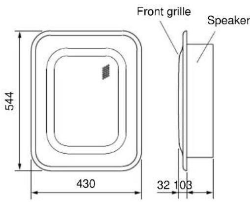
5. NOMENCLATURE AND DIMENSIONS
[Front]
text_image
Front grille Speaker 544 430 32 103[Side]
[Rear]

natural_image
Simple line drawing of a rectangular frame with a central circular recess and corner markers (no text or symbols)(Unit: mm)
- Mounting bracket (standard accessory)

text_image
Hook clip 520 352[Bottom]
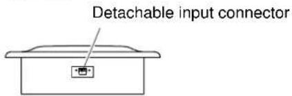
text_image
Detachable input connector6. INSTALLATION
6.1. Contents
Check to be sure that the following components are available in a complete set before installation:
Speaker ..... 1 Mounting bracket ..... 1 Front grille ..... 1 Anchoupee template ..... 1
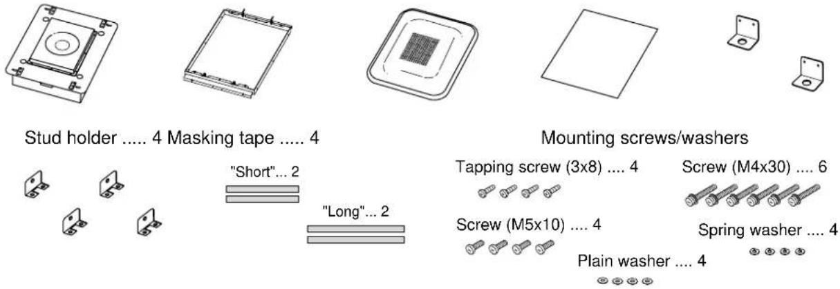
text_image
Stud holder .... 4 Masking tape .... 4 "Short"... 2 "Long"... 2 Mounting screws/washers Tapping screw (3x8) .... 4 Screw (M4x30) .... 6 Screw (M5x10) .... 4 Spring washer .... 4 Plain washer .... 46.2. Flush Wall or Ceiling Mounting
6.2.1. Flush wall mounting
[Front]

natural_image
Simple geometric diagram of nested rounded rectangles with a small symbol inside (no text or labels)[Vertical cross-sectional]

text_image
HB-1 Wall Fixing screw Mounting bracket[Horizontal cross-sectional]
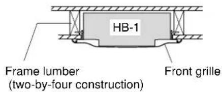
text_image
HB-1 Frame lumber (two-by-four construction) Front grille6.2.2. Installation order
Step 1. Using the supplied cutout template, make a 360x480 mm mounting hole in the wall or ceiling panel.
Note
- There must be at least 103 mm of depth behind the wall or ceiling panel.
- The unit is mountable on the panel with thickness of 12 – 33 mm.

text_image
Mounting hole 480 mm 360 mm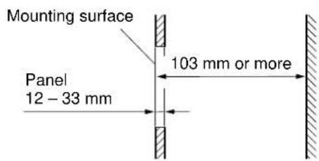
text_image
Mounting surface 103 mm or more Panel 12 - 33 mmStep 2. Loosen the screws of the hook clips (4 places) attached to the mounting bracket and leave each screw sticking out approximately 2 mm.
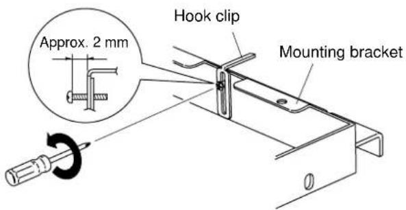
text_image
Approx. 2 mm Hook clip Mounting bracketStep 3. Insert the mounting bracket into the hole made in Step 1, and mount it to the back of the wall or ceiling panel. To mount, clamp the wall or ceiling panel with the hook clips (4 places), then tighten the hook clip screws.
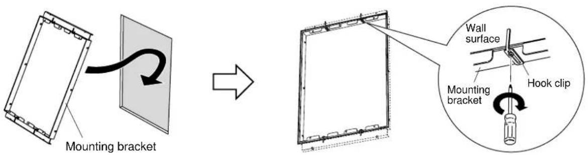
text_image
Mounting bracket Wall surface Mounting bracket Hook clipStep 4. Fix the mounting bracket to the wall or ceiling panel.
[When mounting the bracket to two-by-four construction]
Secure the bracket to the frame lumbers from the inside (3 places on the left and 3 places on the right side) of the bracket.
Note: Prepare the screws (not supplied with the unit) that are appropriate for the frame lumbers.
![TOA HB-1 - [When mounting the bracket to two-by-four construction] - 1](/content/2026/06/1177361/images/31494e730e2d13832139907eb6fb2233304cba278b352cf7501df47ae54b5b8f.jpg)
text_image
Mounting bracket Screw for frame lumber Frame lumber (two-by-four construction)[When mounting the bracket to the ceiling panel]
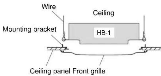
Caution: Be sure to suspend the bracket using wires or bolts.
Wire suspension: Use 4 mounting holes in the bracket.
Bolt suspension: Mount the supplied anchor piece (2 pieces) to the bracket.
![TOA HB-1 - [When mounting the bracket to the ceiling panel] - 1](/content/2026/06/1177361/images/d51d95b6a30db4b6b402b1c8ae806cbc29f7ff3df04b01761d126100a1a28bf3.jpg)
text_image
Wire Mounting bracket![TOA HB-1 - [When mounting the bracket to the ceiling panel] - 2](/content/2026/06/1177361/images/5ee61d66bdc4e8c00fbf0919627fb836392cc372e365302a734efd59c66b39ac.jpg)
text_image
Bolt Anchor piece Spring washer Mounting bracket Plain washer M5x10 screwStep 5. Install the supplied speaker fixing screws (4 pieces with M4x30 plain and spring washers) in the mounting bracket so that they are left sticking out 2 - 3 mm from the mounting surface. (They are tightened in Step 10.)
![TOA HB-1 - [When mounting the bracket to the ceiling panel] - 3](/content/2026/06/1177361/images/a88859a4303928f45f7fd906d1cfb8fc67b8af711ddcd95e18a198cd112edbe7.jpg)
text_image
2 - 3 mm Fixing screw Mounting bracketStep 6. Loosen the unit's lock tab screws (4 places) and leave them sticking out 2 - 3 mm. (They are tightened in Step 10.)
![TOA HB-1 - [When mounting the bracket to the ceiling panel] - 4](/content/2026/06/1177361/images/e272f1b85171d907d800fe5dcbec1780505642018b64430c594e9700ccccb172.jpg)
text_image
Lock tab 2 - 3 mmStep 7. Connect the speaker cable to the detachable connector.
Note: Solid or stranded cables with a cross-sectional area of 0.2 - 2.5 mm^2 (corresponding to AWG24 – 14) can be used.
Step 7-1. Detach the input connector from the unit's connector socket and loosen the screws of the terminals to use with a screwdriver.
![TOA HB-1 - [When mounting the bracket to the ceiling panel] - 5](/content/2026/06/1177361/images/d6086d66b13a41b7dd6b0f857a7d463f9e9599518cca1ee9c6e343a9c4a6a10c.jpg)
text_image
Detachable input connector SpeakerStep 7-2. Insert stripped cable ends into the terminals, then retighten the terminal screws.
[Single connection]
![TOA HB-1 - [When mounting the bracket to the ceiling panel] - 6](/content/2026/06/1177361/images/08efda84c53496f95e257a961596d40d127bff2e759d45e1bda0f69bb76b85da.jpg)
text_image
5 mmNote: Tighten the screws of the unused terminals to prevent resonance noise.
[Bridge connection]
![TOA HB-1 - [When mounting the bracket to the ceiling panel] - 7](/content/2026/06/1177361/images/94ff3d919e85477c99a2a889e42ce9755c139a851ea802a81fe7a2f23970cdb3.jpg)
text_image
From amplifier To next sub-woofer systemStep 8. Reinsert the detachable input connector into the unit's socket, then fit the unit in the mounting bracket.
![TOA HB-1 - [When mounting the bracket to the ceiling panel] - 8](/content/2026/06/1177361/images/50dedf04d212baac5251bd9882254961ca116dcbfb18785b0dcaba081c406da3.jpg)
text_image
Detachable input connector Mounting bracketStep 9. Rotate the lock tabs (4 places) until each contacts the fixing screw head left sticking out in Step 5.
![TOA HB-1 - [When mounting the bracket to the ceiling panel] - 9](/content/2026/06/1177361/images/8ffbc72fccf1d00ef5e2f1d6c64cfe01329b3c9a93d1873fb0d079f59b754572.jpg)
text_image
Fixing screwLock tab Lock tab screwStep 10. Retighten both the fixing screws (4 places) and lock tab screws (4 places).
![TOA HB-1 - [When mounting the bracket to the ceiling panel] - 10](/content/2026/06/1177361/images/48cd59d196550bef5f58d8f5dca3578b76ffbd0de271b0f438e531e14d75d7ed.jpg)
text_image
es) and lock tab screws (4 places). Lock tabStep 11. Using two more supplied fixing screws, fix the unit to the mounting bracket securely at two places shown in the figure.
Note: After completing all of the above steps, check to ensure that the unit is fixed securely to the wall or ceiling panel surface.
![TOA HB-1 - [When mounting the bracket to the ceiling panel] - 11](/content/2026/06/1177361/images/d5489af70324e4dcf3aad151ce48cb111908ecb705b2cc4e6bad4d6255b60a8c.jpg)
text_image
Fixing screwStep 12. Align the front grille with the speaker so that the four stud screws align with the unit's corresponding stud receptacles, then push the grille onto the speaker.
![TOA HB-1 - [When mounting the bracket to the ceiling panel] - 12](/content/2026/06/1177361/images/8e1374a8326ddd809aad245f356f24eaae285f7caf2e36b29c5bbe4bca7a9607.jpg)
text_image
Front grille Stud receptacle6.3. Suspending the Unit in the Ceiling
When suspending the HB-1 speaker in the ceiling, remove the lock tabs and suspend the unit using bolts or wires at the resultant 12 mm-diameter holes. The front grille can be mounted directly to the ceiling panel using the supplied mounting bracket.

text_image
12 mm-diameter hole Remove lock tabs.6.3.1. Suspending the unit [Wire Suspension]
text_image
Wire Mounting bracket Ceiling HB-1 Ceiling panel Front grille[Bolt suspension]

text_image
Bolt Mounting bracket Ceiling HB-1 Ceiling panel Front grille6.3.2. Front grille installation
Step 1. Before mounting the front grille directly to the ceiling panel,
Step 1-1. Attach the four supplied stud holders to the mounting bracket using the four supplied tapping screws.
Step 1-2. Detach the stud receptacles from the main speaker unit and attach them to the stud holders.
Step 2. Mount the mounting bracket to the ceiling panel. (Follow Steps 1.-4. on P. 4 "Flush Wall or Ceiling Mounting.")
Step 3. Attach the masking tapes to the ceiling panel as shown on the right to prevent the white ceiling panel from being seen through the front grille meshes.
Step 4. Align the front grille with the speaker so that the four stud screws align with the unit's corresponding stud receptacles, then push the grille onto the speaker.

text_image
Tapping screw (supplied with the unit) Stud receptacle (Remove from the unit) 1-2 Stud holder (supplied with the unit) 1-1 Mounting bracket Use the screws removed when detaching the stud receptacles.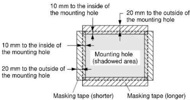
text_image
10 mm to the inside of the mounting hole 20 mm to the outside of the mounting hole 10 mm to the inside of the mounting hole Mounting hole (shadowed area) 20 mm to the outside of the mounting hole Masking tape (shorter) Masking tape (longer)7. MATCHING TRANSFORMER INSTALLATION
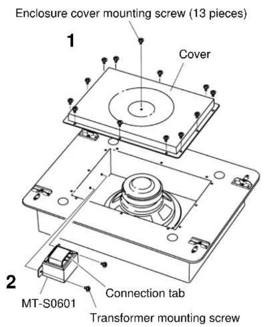
An optional MT-S0601 matching transformer can be installed in the HB-1 speaker.
text_image
Enclosure cover mounting screw (13 pieces) 1 Cover 2 MT-S0601 Connection tab Transformer mounting screw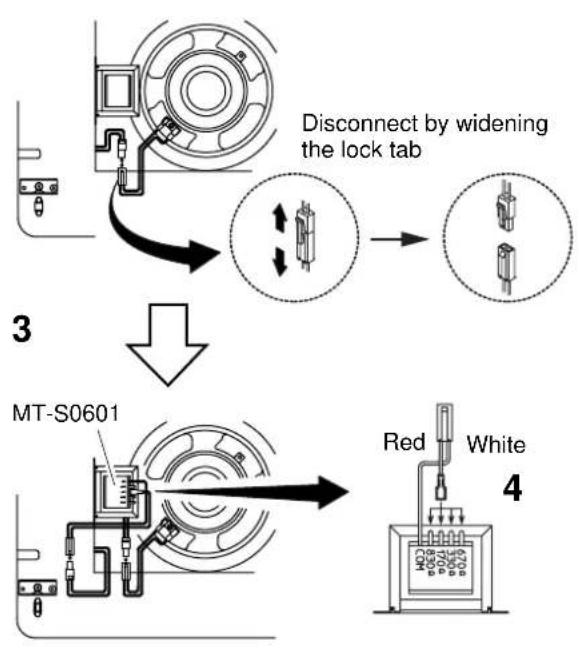
flowchart
graph TD
    A["Start"] --> B["Connect"]
    B --> C["Disconnect by widening the lock tab"]
    C --> D["Close-up of lock tab"]
    D --> E["MT-S0601"]
    E --> F["Red/White 4"]
Step 1. Remove the 13 enclosure cover fixing screws to detach the cover.
Step 2. Remove the two screws located inside an enclosure. Using the removed two screws, mount the MT-S0601 transformer so that its connection tab is facing the front of the enclosure.
Step 3. Detach the woofer's lead wire junction connector, and connect it to the MT-S0601's connector.
Step 4. Connect the speaker input cable to the desired impedance tap.
Step 5. Replace the enclosure cover.
Step 6. Choose an appropriate impedance indication label from those supplied with the MT-S0601, and affix it over the HB-1's nameplate to indicate the selected impedance.
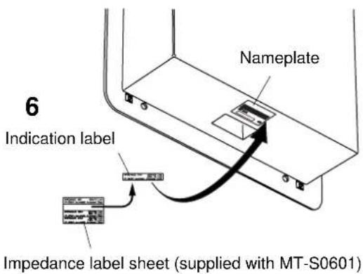
text_image
6 Indication label Nameplate Impedance label sheet (supplied with MT-S0601)8. CROSSOVER CONNECTIONS WITH A FULL-RANGE SPEAKER
8.1. Recommended Filters for the HB-1
- Because the HB-1's enclosure construction is designed to create an acoustic band-pass filter, the mid and high frequency audio ranges are cut even if the input signal band is not limited with a low-pass filter. Therefore, the HB-1 functions as a sub-woofer with no filtering.
HB-1's cross section

natural_image
Pure mechanical diagram showing a piston-cylinder assembly with directional arrows, no text or symbols present.Frequency-to-SPL relationship
(1 W 1 m, 1/2 free sound field)
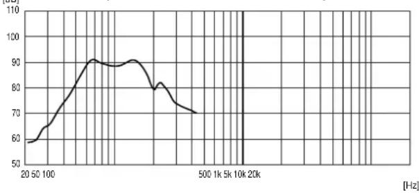
line
| Frequency [Hz] | Amplitude | | -------------- | --------- | | 20 | 60 | | 50 | 70 | | 100 | 85 | | 150 | 90 | | 200 | 88 | | 250 | 85 | | 300 | 80 | | 350 | 75 | | 400 | 70 | | 450 | 68 | | 500 | 65 | | 550 | 63 | | 600 | 62 | | 650 | 61 | | 700 | 60 | | 750 | 59 | | 800 | 58 | | 850 | 57 | | 900 | 56 | | 950 | 55 | | 1000 | 54 | | 1050 | 53 | | 1100 | 52 | | 1150 | 51 | | 1200 | 50 | | 1250 | 49 | | 1300 | 48 | | 1350 | 47 | | 1400 | 46 | | 1450 | 45 | | 1500 | 44 | | 1550 | 43 | | 1600 | 42 | | 1650 | 41 | | 1700 | 40 | | 1750 | 39 | | 1800 | 38 | | 1850 | 37 | | 1900 | 36 | | 1950 | 35 | | 2000 | 34 |- The speaker driving efficiency can be increased by inserting a low-pass filter before the power amplifier to cut the mid and high frequency components of the input signal to the sub-woofer.
- The following filter settings are recommended when using a digital signal processor for the HB-1's signal system:
High-pass filter (− 12 dB/oct):
Cut-off frequency=40 Hz, Q=1.0
Low-pass filter ( -12 dB/oct ):
Cut-off frequency=100 Hz, Q=1.0
Frequency-to-gain relationship
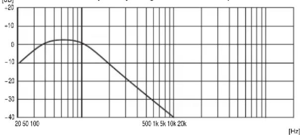
line
| Frequency [Hz] | Amplitude | | -------------- | --------- | | 20 | -10 | | 50 | -5 | | 100 | 0 | | 200 | 5 | | 500 | -10 | | 1k | -20 | | 5k | -30 | | 10k | -40 | | 20k | -45 |8.2. Level Balance and Polarity
When using the HB-1 in combination with TOA's F or H series Full-Range Speakers, adjust their level balance or polarity depending on the conditions of the installation location.
8.2.1. Level balance adjustment
Adjust the level of the sub-woofer or full range speaker depending on the number of units to be installed or installation conditions.
8.2.2. Polarity adjustment
- Acoustic energy increases at the crossover band for the sub-woofer and full-range speaker if the two speaker are in phase with each other, and decreases if out of phase. Because the phase characteristics of both the sub-woofer and the full-range speaker vary continuously depending on frequency, simply matching the connector polarities of the sub-woofer is not always the best procedure.
- To confirm how much the acoustic energy increases or decreases, reverse the polarity of the sub-woofer's "+" and "-" connectors and select the connection polarity that results in the largest output of acoustic energy. (The use of a real-time spectrum analyzer to check the degree of energy increase is highly recommended.)
9. CAUTIONS CONCERNING HIGH-IMPEDANCE APPLICATIONS
To avoid damaging the HB-1 speaker in high-impedance applications (with the MT-S0601 matching transformer installed), be sure to observe the following conditions:
- Do not limit the input signal band using such devices as a low-pass filter, but instead drive the speaker with the full-range signal.
- Use a high-impedance amplifier with a power rating higher than the wattage tap selected on the matching transformer.
Note
There is a low-frequency threshold for both the speaker matching transformer and the high-impedance amplifier output transformer.
[Matching transformer low-frequency threshold]
If a signal with frequencies lower than the low-frequency threshold is applied at rated power, the transformer's primary impedance (input impedance) decreases abruptly due to core magnetic saturation. With the MT-S0601, the impedance begins to decrease at approximately 40 Hz for the rated input power of 60 W, and is almost halved at 30 Hz. If the speaker is used under this condition, an increased load is put on the power amplifier as well as the matching transformer, causing potential equipment damage.
The low-frequency threshold varies depending on the selected transformer tap, and the smaller the tap-selected wattage, the lower the threshold.
[High-impedance amplifier low-frequency threshold]
When a full-range signal (not band-limited) is applied, the amplifier is not adversely affected. However, if the signal is band-limited with a low-pass filter and driven with rated power, an increased load is put on the output stage, causing potential amplifier damage.
10. SPECIFICATIONS
| Enclosure Type Acoustic Super Woofer system | |
| Power Handling Continuous program: 240 W (40 – 200 Hz)Continuous pink noise: 80 W (40 – 200 Hz) | |
| Rated Impedance 8 Ω | |
| Sound Pressure Level 91 dB (1W, 1m), installation in 1/2 free sound field85 dB (1 W, 1m), installation in free sound field | |
| Frequency Response 45 – 200 Hz (-10 dB, installation in 1/2 free sound field) | |
| Speaker Element 20 cm cone type | |
| Input Terminal Detachable screw terminal, (+)/(-): 2 each (for bridge connection) | |
| Usable Cable Solid or stranded cable: 0.2 – 2.5 mm ^2 (corresponding to AWG24 – 14) | |
| Finish Enclosure Rolled steel plate, black, paint | |
| Front Grille Rolled steel plate, white, paint | |
| Grille Frame Fire-resistant ABS resin (UL 94V-0), white, paint | |
| Mounting bracket Rolled steel plate, black, paint | |
| Dimensions 430 (w) x 544 (h) x 135 (d) mm | |
| Weight | 11 kg (front grille and mounting bracket excluded) |
| Optional Matching Transformer | MT-S0601 (rated at 60 W) |
Note: The design and specifications are subject to change without notice for improvement.
- Accessories
Mounting bracket 1
Front grille 1
Anchor piece 2
Stud holder 4
Pattern paper 1
Masking tape (long and short) 2 each
Mounting screws
M5x10 (for anchor piece) 4
3x8 (for stud holder) 4
M4x30 with plain and spring washers 6
Spring washer (M5 for anchor piece) 4
Plain washer (M5 for anchor piece) 4