U-16P - Microphone ALTO - Free user manual and instructions
Find the device manual for free U-16P ALTO in PDF.

User questions about U-16P ALTO
0 question about this device. Answer the ones you know or ask your own.
Ask a new question about this device
Download the instructions for your Microphone in PDF format for free! Find your manual U-16P - ALTO and take your electronic device back in hand. On this page are published all the documents necessary for the use of your device. U-16P by ALTO.
USER MANUAL U-16P ALTO
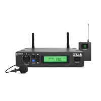
natural_image
Product photo of a black audio workstation with external earphones and a microphone, plus a separate display unit (no visible text or symbols)
CAUTION
RISK OF ELECTRIC SHOCK DO NOT OPEN

TO REDUCE THE RISK OF ELECTRIC SHOCK PLEASE DO NOT REMOVE THE COVER OR THE BACK PANEL OF THIS EQUIPMENT. THERE ARE NO PARTS NEEDED BY USER INSIDE THE EQUIPMENT. FOR SERVICE, PLEASE CONTACT QUALIFIED SERVICE CENTERS.

This symbol, wherever used, alerts you to the presence of un-insulated and dangerous voltages within the product enclosure. These are voltages that may be sufficient to constitute the risk of electric shock or death.

This symbol, wherever used, alerts you to important operating and maintenance instructions.
Please read.

Protective Ground Terminal
AC mains (Alternating Current)

Hazardous Live Terminal
ON: Denotes the product is turned on.
OFF: Denotes the product is turned off.
CAUTION
Describes precautions that should be observed to prevent damage to the product.
-
Read this Manual carefully before operation.
-
Keep this Manual in a safe place.
-
Be aware of all warnings reported with this symbol.
-
Keep this Equipment away from water and moisture.
-
Clean it only with dry cloth. Do not use solvent or other chemicals.
-
Do not damp or cover any cooling opening. Install the equipment only in accordance with the Manufacturer's instructions.
-
Power Cords are designed for your safety. Do not remove Ground connections! If the plug does not fit your AC outlet, seek advice from a qualified electrician. Protect the power cord and plug from any physical stress to avoid risk of electric shock. Do not place heavy objects on the power cord. This could cause electric shock or fire.
-
Unplug this equipment when unused for long periods of time or during a storm.
-
Refer all service to qualified service personnel only. Do not perform any servicing other than those instructions contained within the User's Manual.
-
To prevent fire and damage to the product, use only the recommended fuse type as indicated in this manual. Do not short-circuit the fuse holder. Before replacing the fuse, make sure that the product is OFF and disconnected from the AC outlet.
WARNING
To reduce the risk of electric shock and fire, do not expose this equipment to moisture or rain.

Dispose of this product should not be placed in municipal and should be separate collection.
- Movethis Equipment only with a car stand, tripod, or bracket,
specified by the manufacturer, or sold with the Equipment. When a cart is used, use caution when moving the cart / equipment combination to avoid possible injury from tip-over.

natural_image
Silhouette of a person pushing a large rectangular block within a circular frame (no text or symbols)- Permanent hearing loss may be caused by exposure to \ extremely high noise levels. The US. Government's Occupational Safety and Health Administration (OSHA) has specified the permissible exposure to noise level.
These are shown in the following chart:
| HOURS X DAY | SPL | EXAMPLE |
| 8 | 90 | Small gig |
| 6 | 92 | train |
| 4 | 95 | Subway train |
| 3 | 97 | High level desktop monitors |
| 2 | 100 | Classic music concert |
| 1,5 | 102 | |
| 1 | 105 | |
| 0,5 | 110 |
0,25 or less 115 Rock concert
According to OSHA, an exposure to high SPL in excess of these limits may result in the loss of heat. To avoid the potential damage of heat, it is recommended that Personnel exposed to equipment capable of generating high SPL use hearing protection while such equipment is under operation.
The apparatus shall be connected to a mains socket outlet with a protective earthing connection.
The mains plug or an appliance coupler is used as the disconnect device, the disconnect device shall remain readily operable.
IN THIS MANUAL:
- INTRODUCTION....1
- FEATURES....3
- CONTROL ELEMENTS....3
- OPERATION....8
- TECHNICAL SPECIFICATIONS....10
- WARRANTY....12
1. INTRODUCTION
Thanks for purchasing the ▲LTO wireless microphone system. The U-16R/16H/16P series is the delicately designed UHF, PLL synthesized system, with antenna built inside the receiver for smart switching diversity control, the higher level RF signals maybe fed into the system for greater reliability and coverage, therefore, the risks of breakdown and interference are to be effectively reduced. You can manually adjust the channel of the transmitter to match that of the receiver if you know about the operating frequency of it.
Enjoy your U-16 series and make sure to read this Manual carefully before operation!
1. U-16R, PLL UHF DIVERSITY RECEIVER
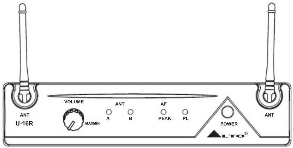
text_image
VOLUME MAXMIN ANT A B AF PEAK PL POWER LTO® ANT U-16R2. Either one of the following transmitters:
U-16H, HANDHELD TRANSMITTER
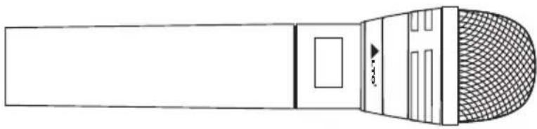
natural_image
Line drawing of a microphone with mesh grille and handle (no text or symbols)1. INTRODUCTION
U-16P, BODY PACK TRANSMITTER
U-16P: A bodypack transmitter with belt clip. The bodypack transmitter will come with either:
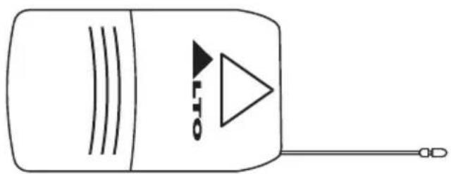
natural_image
Simple line drawing of a device with a triangular play button and antenna (no text or symbols)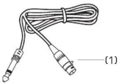
natural_image
Line drawing of a cord with two connectors, labeled (1) at the end (no text or symbols on the cable itself)(1). A cable to be connected to an electric guitar or bass.
(2). A Lavalier Microphone. This is the little "bug" to be clinipples, etc.
(3). A Headset Microphone that is fit like a pair of sunglasses so that the Player has both hands free to play an instrument, dance, shot the Audience, etc.

natural_image
Line drawing of a cable with two connectors and a connector, labeled (2), no text or symbols present.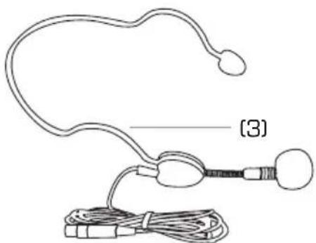
natural_image
Line drawing of a handheld electronic device with wires and connectors (no text or symbols)LM-10, Clip microphone
Preset Impedance: 680 ohm
Freq. Response: 50-12 kHz;
Sensitivity: - 65 dB 3 dB at 1 kHz
Directional: Φ 12×180 mm(Φ47" 7×1")
Weight: 22g(0.049lb)
HM-38, Condenser microphone
Preset Impedance: 600 ohm
Freq. Response: 80-12 kHz;
Sensitivity: -68 dB+/-3 dB at 1kHz;
Directional: Uni-directional;
Weight: 52g (0.12lb)
2. FEATURES
- FEATURES OF U-16R, PLL UHF DIVERSITY RECEIVER
▲ 2 Antennas and Switching diversity control
▲ LED indication for RF, AF PEAK and POWER
▲ Output volume control
▲ Squelch control to minimize therefore interferences
- FEATURES OF U-16H AND U-16P TRANSMITTERS
▲ Soft touch painting for comfortable use
▲ Channel frequency adjusted manually
- COMMON FEATURES
▲ PLL synthesized design
▲ Consistent operating frequencies to comply with the EMC regulations
▲ 16 channel frequency presets
▲ Manufactured under ISO9000: 2000, ISO/TS16949: 2002 quality management System

3. CONTROL ELEMENTS
3.1 U-16R, PLL UHF Diversity Receiver
THE FRONT PANEL
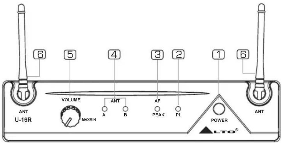
text_image
6 5 4 3 2 1 6 VOLUME ANT A B AF PEAK PL POWER MAXMIN U-16R ANT ANT LTO®1 Power Switch
It switches your U-16R ON and OFF.

3. CONTROL ELEMENTS
2 Power LED
This LED lights up when the receiver is powered on and vice versa.
3 AF Peak LED
This LED lights up when the signal reaches PEAK and you will get distortion.
4 RF LED
This LED lights up when antenna receives signals.
Note: U-16R has two antennas. LED A lights up when antenna A receives more signals than antenna B. LED B lights up when antenna B receives more signals than antenna A.
5 Volume Control
It is used to adjust the volume of your U-16R.
6 Antennas
The antennas receive the signals from transmitter.
THE REAR PANEL
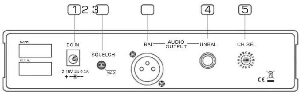
text_image
1 2 3 MODEL SERIAL DC IN SQUELCH MAX BAL—AUDIO OUTPUT—UNBAL CH SEL 12-18V = 0.3A CE1 DC Input
You can connect the supplied AC Adapter to this socket.
2 Squelch Control
It is used to adjust the squelch level by using an adjusting bar which is placed in the microphone. The adjustable squelch range is 95.0\~65.0 dB.
3 Audio Output XLR
To connect a balanced cable with XLR connector (we forgot to tell you that although your U-16 system is wireless, you still need to connect the receiver to your Mixing Desk and to a wall plug!)
4 Audio Output Jack
To be used with an unbalanced cable and standard 1/4" mono jack.
5 Frequency Band Selector
Using a select bar, you can select the right frequency band you want.
3.2 U-16H, Handheld Transmitter
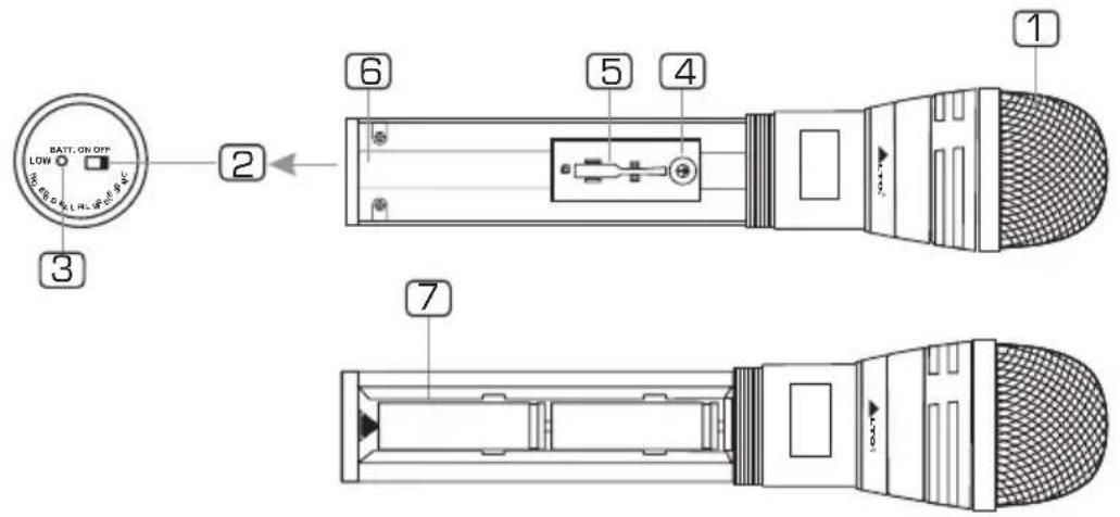
text_image
BATT. ON OFF LOW 3 2 6 5 4 1 71 Front Grill
This spring steel mesh grill will protect the microphone capsule during a live performance. Especially made for heavy metal players, alcohol, drugs, etc.
2 Power Switch
Set the power switch to "ON" position, then the microphone is turned on and the BATT LED flashes once. Set the power switch on "OFF" position, then the microphone is turned off and the BATT LED lights off slowly.
3 Power LED
When the unit is turned on, this LED flashes once. When the unit is turned off, this LED lights off slowly. When the batteries are short of power, this LED lights up.
4 Band Selector
With an adjusting bar, the band selector can be used to switch to an expected frequency. Before switching frequencies, turn off the microphone first and then turn on it.
5 Adjusting Bar
This adjusting bar is placed in the microphone. It is used to adjust squelch control and band selector for switching frequencies.
6 Antenna
The antenna is integrated into the transmitter body for transmitting signals.
7 Battery Compartment
This unit may be powered from one pair dry or rechargeable batteries, size AA 1.5 V.
3.3 U-16P, Body Pack Transmitter
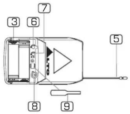
text_image
3 6 7 5 8 9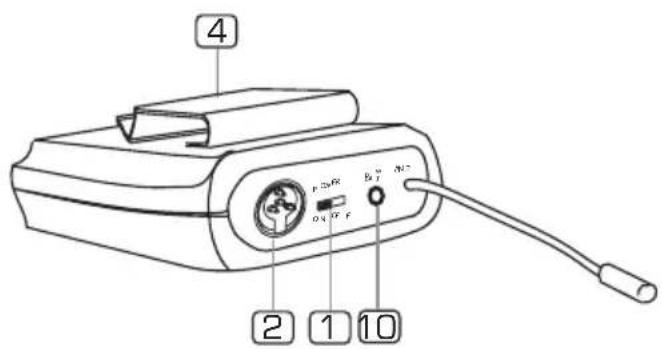
text_image
4 2 1 101 Power Switch
Set the power switch in the position "ON", then the microphone is turned on and flashes once. Set the power switch in the position "OFF", then the microphone is turned off and the BATT LED lights off slowly.
2 MINI 4P Connector
This connector is used to connect the unit with the clip microphones, for example, HM-38 condenser microphone or LM-10 clip microphone.
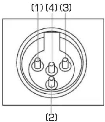
text_image
(1) (4) (3) (2)Pin 1 GND
Pin 2 Phantom power supply for condenser microphone
Pin 3 For guitar, bass and keyboards
Pin 4 For dynamic or condenser microphone
3 Battery Compartment
This unit may be powered from one pair dry or rechargeable batteries, size AA 1.5 V.
4 Belt Clip
It is the detachable belt clip for easy carry during the live applications.
5 Antenna
It is a flexible antenna. To get effective transmission, never cover the antenna with hand, clothes, etc during the operation, and always position the transmitter nearby the receiver.

3. CONTROL ELEMENTS
6 GT Switch
It is used to adjust the input signal level of electrical guitar. When an electrical guitar is being used, it is ineffective to adjust MT switch.
7 MT Switch
It is used to adjust the input signal level of microphone. When an microphone is being used, it is ineffective to adjust GT switch.
8 Band Selector
With the adjusting bar, the band selector can be used to switch to an expected frequency before switching the frequencies, turn off the transmitter first and then turn on it.
9 Adjusting Bar
It is used to adjust BAND SELECTOR, MT SWITCH and GT SWITCH.
10 POWER LED
When the unit is turned on, this LED flashes once. When the unit is turned off, this LED lights off slowly. When the batteries are short of power, this LED flashes. When the batteries can not be used, this LED lights up.
4.1 FOR the U-16R, PLL UHF DIVERSITY RECEIVER
- Manually Selecting Frequency
With an adjusting bar, adjust the band selector to select the right frequency which matches the frequency of transmitter.
- Output Volume Control
It is used to control the output volume. Turn the knob clockwise, the output volume will increase. Turn the knob counter-clockwise, the output volume will decrease.
- Squelch Control
The job of a squelch circuit is to reduce audible noise. It eliminates noise during Pauses in the audio signal by muting the receiver every time and the audio level drops below a defined threshold. The squelch control on the receiver sets this threshold. Use the squelch control with care! If the squelch threshold is too high, the squelch will not only cut out noise but mute quiet audio signals as well because the squelch responds to the detected voltage and cannot distinguish between wanted signal and noise. Besides that, a too high squelch threshold also decreases the usable range. The squelch range is 95.0 dB\~65.0 dB. Use an adjusting bar to adjust the squelch selector for a right squelch threshold.
4.2 FOR the U-16H/16P TRANSMITTER
- Frequency Select
In practice, to effectively avoid the interference from any lighting equipment, computers, fax machines, etc nearby. It is usually advised to switch to another frequency to get best performance. The frequency range of this system is UHF, 798 MHz \~ 827 MHz, and it is divided into 16 frequency bands according to the country's EMC regulations; Each frequency band can be manually adjusted with an adjusting bar. If you want to switch a frequency, you have to turn off the unit, adjust frequency and then turn it on again.
- Battery Replacing And Charging
Please be advised to use only one pair of AA 1.5 V batteries for power supply.
※Note: Danger of explosion if battery is incorrectly replaced. Replace the batteries only with the same or equivalent type.
4.3 Operating frequency matches between Receiver and Transmitter
To make the operating frequency matched between the transmitter and the receiver, adjust the transmitter and receiver manually with the adjusting bar for the same frequency. Please refer to the following table for selecting frequency.
Caution:
a: If several apparatus are used at the same time, the same frequency can not be used for them.
b: Ten channels can be used simultaneously at most. They are respectively CH 0, CH 1, CH 3, CH 4, CH 6, CH 7, CH 8, CH 9, CH E, CH F. The rest 6 channels are available for customer's choice.
| CH O~CH F | FREQUENCY |
| 0 | 798.125 MHz |
| 1 | 798.325 MHz |
| 2 | 798.925 MHz |
| 3 | 799.325 MHz |
| 4 | 800.725 MHz |
| 5 | 802.725 MHz |
| 6 | 805.725 MHz |
| 7 | 807.925 MHz |
| 8 | 811.525 MHz |
| 9 | 815.725 MHz |
| A | 820.825 MHz |
| B | 822.725 MHz |
| C | 823.225 MHz |
| D | 824.625 MHz |
| E | 825.425 MHz |
| F | 826.625 MHz |
5. TECHNICAL SPECIFICATIONS
| MODEL | U-16R |
| Channel | Single-Channel |
| Receiver type | Diversity |
| Oscillation mode | PLL UHF SYNTHESIZED |
| Frequency band | UHF 798~827 MHz |
| Frequency response | 50 Hz~50 kHz (±3 dB) |
| Frequency stability | ±0.005% |
| Modulation mode | FM (F3E) |
| T.H.D | <1% |
| Dynamic | >100 dB |
| Audio output | Unbalanced 6.3 mm phone jack 280 mV ± 15 kHz deviation |
| Balance output | 360 mV at 15 kHz deviation |
| S/N Ratio | >90 dB |
| RF sensitivity | - 100 dbm/ 30 dB sinad |
| Power supply | DC 12 V/500 mA (AC 115 V/230 V 50/60 Hz adaptor) |
| Dimensions | 130 (W) 44 (H) 2Q1 ( ) D |
| Weight | 0.365 Kg (Approx.) |
| MODEL | U-16H |
| Oscillation mode | PLL UHF SYNTHESIZED |
| Carrier frequency band | UHF 798~827 MHz |
| Frequency response | 50 Hz~15 kHz (8 dB) |
| Frequency stability | ±0.005% |
| T.H.D | <0.8% |
| Modulation mode | FM (F3E) |
| RF output power | 10 mW |
| Dynamic | >100 dB |
| Tone frequency | 32.768 kHz |
| Current drain | <150 mA |
| Max. Deviation | ±35 kHz deviation |
| Battery | "AA" type & pcs (battery life: more than 6 hours) |
| Microphone Capsule | Dynamic capsule |
| Dimensions | 220 mm x 48.8 mm |
| Weight | 0.16 kg (Approx.) |
5. TECHNICAL SPECIFICATIONS
| MODEL | U-16P |
| Oscillation mode | PLL UHF SYNTHESIZED |
| Carrier frequency band | UHF 798~827 MHz |
| Frequency response | 50 Hz~15 kHz (3 dB) |
| Frequency stability | ±0.005% |
| T.H.D | <0.8% |
| Modulation mode | FM (F3E) |
| RF output power | 10 mW |
| Dynamic | >100 dB |
| Tone frequency | 32.768 kHz |
| Current drain | <150 mA |
| Max. deviation | ±35 kHz deviation |
| Battery | "AA" type 2 pcs (use for more than 6 hours) |
| Microphone capsule | Condenser or dynamic capsule |
| 4 bands choice | 1. Condenser |
| 2. Dynamic | |
| 3. Electric instrument | |
| 4. Ground | |
| Dimensions | 65 (W)×11 ( ) 31×(H)D |
| Weight | 0.105 Kg (Approx.) |
6. WARRANTY
1. WARRANTY REGISTRATION CARD
To obtain Warranty Service, the buyer should first fill out and return the enclosed Warranty Registration Card within 10 days of the Purchase Date.
All the information presented in this Warranty Registration Card gives the manufacturer a better understanding of the sales status, so as to provide a more effective and efficient after-sales warranty service. Please fill out all the information carefully and genuinely, miswriting or absence of this card will void your warranty service.
2. RETURN NOTICE
2.1 In case of return for any warranty service, please make sure that the product is well packed in its original shipping carton, and it can protect your unit from any other extra damage.
2.2 Please provide a copy of your sales receipt or other proof of purchase with the returned machine, and give detail information about your return address and contact telephone number.
2.3 A brief description of the defect will be appreciated.
2.4 Please prepay all the costs involved in the return shipping, handling and insurance.
3. TERMS AND CONDITIONS
3.1 warrants that this product will be free from any defects in materials and/or workmanship for a period of 1 year from the purchase date if you have completed the Warranty Registration Card in time.
3.2 The warranty service is only available to the original consumer, who purchased this product directly from the retail dealer, and it can not be transferred.
3.3 During the warranty service, may repair or replace this product at its own option at no charge to you for parts or for labor in accordance with the right side of this limited warranty.
3.4 This warranty does not apply to the damages to this product that occurred as the following conditions:
- Instead of operating in accordance with the user's manual thoroughly, any abuse or misuse of this product.
• Normal tear and wear. - The product has been altered or modified in any way.
- Damage which may have been caused either directly or indirectly by another product / force / etc.
- Abnormal service or repairing by anyone other than the qualified personnel or technician.
And in such cases, all the expenses will be charged to the buyer.
3.5 In no event shall be little for any incidental or consequential damages.
Some states do not allow the exclusion or limitation of incidental or consequential damages, so the above exclusion or limitation may not apply to you.
3.6 This warranty gives you the specific rights, and these rights are compatible with the state laws, you may also have other statutory rights that may vary from state to state.
SEIKAKU TECHNICAL GROUP LIMITED
NO. 1, Lane 17, Sec. 2, Han Shi West Road, Taichung 40151, Taiwan
http://www.altoproaudio.com Tel: 886-4-22313737
email: alto@altoproaudio.com Fax: 886-4-22346757
All rights reserved to ALTO. All features and content might be changed without prior notice. Any photocopy, translation, or reproduction of part of this manual without written permission is forbidden. Copyright 2007 Seikaku Group