AC-EXO-444-KIT - Audio/video converter AVPro Edge - Free user manual and instructions
Find the device manual for free AC-EXO-444-KIT AVPro Edge in PDF.

| Type | 4x4 HDMI Over HDBaseT Matrix Switcher Kit |
| Model | AC-EXO-444-KIT |
| Brand | AVPro Edge |
| Input Ports | 4 x HDMI (Type A Female) |
| Output Ports | 4 x HDBaseT (RJ45) |
| Video Resolution | Up to 4K@60Hz 4:4:4 |
| Audio Support | PCM, Dolby Digital, DTS, up to 7.1 |
| HDCP Compliance | HDCP 2.2 |
| Transmission Distance | Up to 100m over Cat6/7 |
| Control | IR, RS-232, TCP/IP, Web GUI |
| Power Supply | 12V DC, 2A (included) |
| Dimensions (WxHxD) | 17.0" x 1.75" x 6.0" |
| Weight | 3.2 lbs (1.45 kg) |
| Rackmountable | Yes, 1U |
| Operating Temperature | 32°F to 104°F (0°C to 40°C) |
| Storage Temperature | -4°F to 140°F (-20°C to 60°C) |
| Included Accessories | Power adapter, IR remote, RS-232 cable, mounting ears |
| Safety Certifications | CE, FCC, RoHS |
| Warranty | 3 Years |
| Maintenance | Clean with dry cloth, keep vents clear |
Frequently Asked Questions - AC-EXO-444-KIT AVPro Edge
User questions about AC-EXO-444-KIT AVPro Edge
0 question about this device. Answer the ones you know or ask your own.
Ask a new question about this device
Download the instructions for your Audio/video converter in PDF format for free! Find your manual AC-EXO-444-KIT - AVPro Edge and take your electronic device back in hand. On this page are published all the documents necessary for the use of your device. AC-EXO-444-KIT by AVPro Edge.
USER MANUAL AC-EXO-444-KIT AVPro Edge
Fiber Optic Extender with 4K60 4:4:4 support and 18Gbps HDR. ARC, IR, RS232, EDID Management and built in Test Pattern

text_image
AVPro edge AC-EXO-444-R 300m/1000ft@4K 60 4:4:4 & HDR, MM Fiber 2000m/7000ft@4K 60 4:4:4 & HDR, SM Fiber Bidirectional Single Fiber Optical Extender with 2-Way IR & RS232 including AUDIO INJECTION, EXTRACTION & ARC 4K ULTRA HD RECEIVER AV Pro TRANSMITTER HDMI IN RS232 + - HDMI STATUS ↓ TX ↓ RX ↓ IR ↓ 48V USB SETTING TEST Audio IN SELECT BI DIR. SFP HDMI OUT RS232 IR IN IR OUT 48VThis is AVProEdge's flagship Fiber Optic Extender, allowing the user to extend an HDMI signal 2 kilometers via single-mode fiber, and up to 300 meters using multi-mode fiber. You can go even further by installing your own SFP port. It solves problems for both commercial and residential markets for distributing high value 4K 18Gbps content from rack to display. These extenders go the distance, no need to find power and cascade extenders for ultra long runs. Additionally AC-EXO-444 offers solutions for 18Gbps distribution in residential, digital entertainment centers, retail stores, AV events that require reliable and long distance distribution, suitable for Data Center, Control Rooms, Conference Rooms, Schools and Corporate Training environment.
Features
- HDMI 2.0(a/b)
• 18Gbps Bandwidth Support (Using ICT) - Up to 4K60 4:4:4 Support
• Full HDR Support (HDR 10 & 12 Bit)
• HDR, HDR10+ and HLG Support
• Dolby Vision Support - 4K --> 1080P Down-scaling for mixed systems
• EDID Management and EDID emulate - 4K & HD Test Patterns built into Tx and Rx for troubleshooting
• Toslink Multichannel Audio Extraction
• ARC Support (Toslink or HDMI)
• HDCP 2.2 (and all earlier versions supported)
• CEC Pass Through -
3D Support
• 300m (1000ft) on full 4K (Multi-mode OM3)
• 2km (1.25 Miles) on full 4K (Single-mode Fiber) -
HDCP 2.2 & Earlier
• Bi Directional IR Passthrough
• Bi Directional RS232 Transport - I-Pass Feature for control system "pass-through"
- 3-20v protection circuit built in for safe IR transport
• LED Status, Link, Power indication lights - Use single fiber optic cable (Multi-mode or Single-mode
- Removable/changeable SFP for even longer distances
- Supports uncompressed PCM 2-Ch., LPCM 5.1 & 7.1, Dolby Digital, DTS, Dolby TrueHD, DTS HD-Master Audio, Atmos (On HDMI)
- ESD protection circuitry (Inputs & Outputs) to 7KV
- Can Cascade
- Single LC Connector Type
What's in the Box
• AC-EXO-444-TX (Transmitter)
• AC-EXO-444-RX (Receiver)
- 2x 48V Power Supply
- 1 x IR Tx Unit
- 1 x IR Rx Unit
- Mounting Ears
Introduction, Features, In the Box......2
Specifications....3
Fiber Info....4
Transmitter....5-7
Receiver....8-9
RS-232 Configuration.... 10-11
IR Configuration....12-13
Maintenance, Damage Requiring Service....14
Support, Warranty....15
Troubleshooting.... 16
Fiber Basics: Fiber Cable Types
- Single-mode - Typically used for "long hauls" - Typically used for long distance buried cable (ie. used by telecommunication companies for country-wide distribution) -Single-mode should be used in applications over 1000FT (300M).
- Multi-mode - Most common in pro/custom electronics. For shorter runs, up to 1000FT (300M). Multi-mode is used in residential/commercial applications for on premise infrastructure.
Ways to purchase fiber cable:
- Simplex - Means a single strain of fiber optic cable. Comes in a single jacket. Any grade/type can be simplex.
- Duplex - Means two strains of fiber optic cable. Comes in a dual, fused, jacket.
- 6-Strain - Six strains of fiber, comes in a single jacket, each individual fiber will be color coded.
• 12-Strain - Twelve strains of fiber, comes in a single jacket, each individual fiber will be color coded.
OM Grades
OM grades are for multi-mode fiber (OM translates to Optical Multi-mode) only. The grade is determined by the clarity of the glass. The differences are:
- OM1 - (Legacy Fiber) - 200MHz - Typically ORANGE jacket - is compatible with AC-EXO-444 up to 100M.
- OM2 - 500MHz - Typically ORANGE jacket - is compatible with AC-EXO-444 up to 150M.
- OM3 - (Most Common, Recommended) 2000MHz - Typically AQUA jacket - is compatible with AC-EXO-444 up to 300M.
- OM4 - 4700MHz - Typically VIOLET, but can be AQUA jacket - Is compatible with AC-EXO-444 up to ?????
OS Grades
OS grades are for single-mode fiber (OS translates to Optical Single-mode) only. The grade is determined by the clarity of the glass. For Pro AV applications the grade is of little meaning - there are two grades (OS1, OS2) OS1 is considered "legacy". If you buy Single-mode today it will be OS2. The jacket color of single-mode fiber is YELLOW. The AC-EXO-444.
- LC (Lucent Connector) - Universal style, most common (used in networking). Can be terminated in the field, some connectors support more than one strain. AC-EXO-444 uses this connector type.
• SC (Square Connector) - Universal, can be terminated in the field. Single strain of fiber only. - MPO (Multi-fiber Push-On) - Mechanically terminated, for large fiber clusters. Not field friendly.
- Other Types- many other "custom" styles exist, however since there is no consistency, it is not effective in the field and becomes a single use cable.
What is a SFP (Small Form-Factor Pluggable Transceiver)?
An SFP is a great benefit of using fiber. It is a module that allows the user to modify the connector type or quantity, maximum distance, and even the type of fiber used. by using devices with SFP's, you are increasing the life because you can modify the capabilities as needed in the field. SFP Modules are easily and inexpensively attainable.
AVProEdge STRONGLY recommends Cleerline SSF. It has proven to be the strongest, safest, and easiest to terminate in the field.
■ The Transmitter

text_image
USB SETTING AUDIO SPPIF out IR-SELECT BI DR, SFP AVPro edge AC-EXO-444-T 300m/1000ft@4K 60 4:4:4 & HDR, MM Fiber 2000m/7000ft@4K 60 4:4:4 & HDR, SM Fiber Bidirectional Single Fiber Optical Extender with 2-Way IR & RS232 including AUDIO INJECTION, EXTRACTION & ARC 4K ADVANCED ULTRA HD TRANSMITTER HDMI IN RS232 IR IN IR OUT 48V
text_image
Back HDMI IN RS232 + - HDMI STATUS TX ≠ RX IR 48V HDMI In RS232 (COM & Pass-through) 48V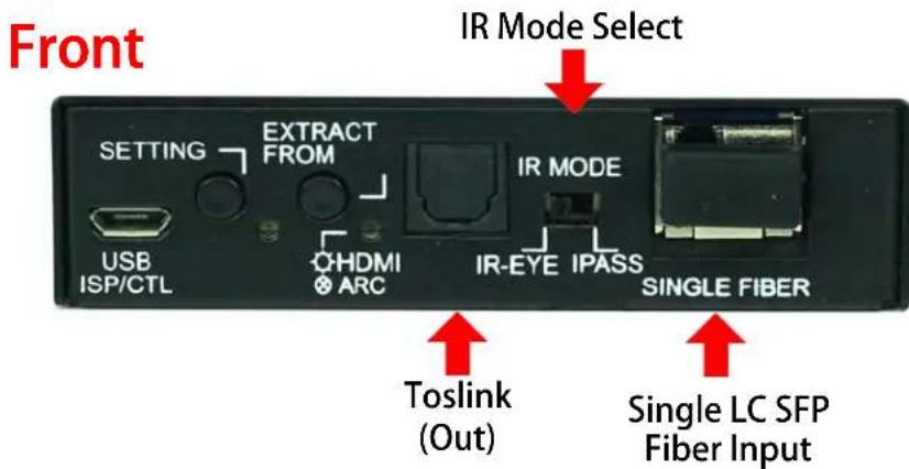
text_image
Front IR Mode Select SETTING EXTRACT FROM IR MODE USB ISP/CTL HQHDMI ⊕ ARC IR-EYE IPASS SINGLE FIBER Toslink (Out) Single LC SFP Fiber InputIndicator Troubleshooting Lights on the Transmitter:
POWER - On the front (Setting Light): (Red) the setting light doubles as the POWER indicator. This is an indicator that the power is connected. There are only two states for light:
• Light Is On = Power supply is connected and functioning.
- Light Is Off = Power supply is not connected or there is no power present. (In order to have power: check the power supply, USP, Outlet, etc...)
HDMI STATUS - On the back (By HDMI Port): (Red) This indicator shows that the HDMI Source is connected. The states are:
• Light Is On (Solid) = Sync w/ HDMI source is correct and solid
• Light Is Flashing = The light flashes during the sync process. If it is flashing continuously, a picture may not be present
• Light Is Off = Sync w/ HDMI source is not detected
If the RED HDMI SIGNAL STATUS LIGHT is flashing or off, check the following:
- The source. Plug it directly into the display to be sure it's functioning properly.
- Try a longer HDMI cable. Some HDMI cables do not sync well at shorter lengths.
- Set the EDID to state #1 (See below).
- If these suggestions do not work, enable the "Test Pattern" (See Below). If you see the pattern, the problem is between the source and the transmitter, please try a different source.
- Contact AVProEdge if these suggestions do not work.
Functions & Setup of the Transmitter:
IR Mode Slide Switch: (On Front) This is used to select a preferred IR Mode
There are two modes:
- IR-EYE - The IR Input will be configured to operate with an IR Receiver Eye.
- I-PASS - The IR Input will be configured to safely operate with a direct connection from a control system using a mono or stereo 3.5mm cable. It's protected @ 3v-20v. Default mode is IR-EYE.
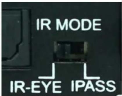
text_image
IR MODE IR-EYE IPASSUsing the Setting Button: (On Front) The setting button can be pressed in different combinations based on what is needed. The status light on the front will flash based on the selection. The selections are in series, meaning, for example, if you are on selection 5 (listed below), you can come back later and press it again to move you to 6, 7, 8, 1, 2, etc... Using an ink pen is best to press the button.
The SETTING BUTTON is located front of the transmitter next to the micro USB port. The indicator light is directly next to the button.
The SETTING BUTTON area looks like this:
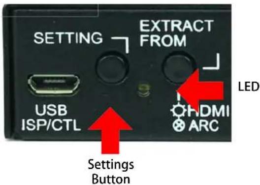
text_image
SETTING EXTRACT FROM USB ISP/CTL LED Settings Button HDMI ARCEDID Management:
Quick press to select EDID
- EDID BYPASS --- LED Flashes 1 Time (Default, from downstream device)
- 1080P_2CH --- LED Flashes 2 Times
- 1080P_8CH --- LED Flashes 3 Times
- 4K60HzY420_3D_2CH --- LED Flashes 4 Times
- 4K60HzY420_3D_8CH --- LED Flashes 5 Times
- 4K60Hz_3D_2CH_HDR--- LED Flashes 6 Times
- 4K60Hz_3D_8CH_HDR --- LED Flashes 7 Times
- USER EDID --- LED Flashes 8 Times
T2 EDID Lights on Page 7.
While in the USER EDID state (8), press and hold the setting button (for 4 seconds) in order to copy the EDID from the connected display or downstream device to the user EDID and it will apply automatically.
Why do this?
This is commonly used when there is a need for a specific, known EDID that the installer may prefer. It can also be used if you want to bypass an EDID of an AVR or another connected device. (IE, plug the extender kit directly into a display and COPY the EDID. Plug it back into an AVR that may not have a current/good EDID).
Scaler Setting:
While in ANY state besides the USER EDID state, press and hold the setting button (for 4 seconds) to toggle the scaler mode.
The options are:
- Normal Mode(ICT Mode) --- LED Flashes 1 Time
- Down Scaler Mode (4K->2K) --- LED Flashes 2 Times
EDID Management:GEN2
(Indicated by part number AC-EXO-444-T-2)
4 LED lights on the board inside the chassis (see below) Corresponding light will be solid, the others will flash

text_image
BI DIR. SFP 1 2 3 4| EDID SETTINGS | |
| LED STATUS | 1-ON 0-OFF |
| EDID BYPASS | 1000 |
| 1080P 2Ch | 0100 |
| 1080P 8Ch | 1100 |
| 4K 60 420 3D 2Ch | 0010 |
| 4K 60 420 3D 8Ch | 1010 |
| 4K 60 3D 2Ch HDR | 0110 |
| 4K 60 3D 8Ch HDR | 1110 |
| USER EDID | 0001 |
Functions & Setup of the Transmitter Cont.:
Using the "Extract From" Button: (On Front)
This function allows you to select where the Toslink audio output gets its signal.
There are two options:
- Extract from HDMI - The RED light will be on. Audio will be extracted from the local HDMI input plugged into the transmitter. The supported formats are 2CH PCM, 6CH/7CH LPCM, DTS 5.1, Dolby Digital, Dolby Digital Plus. No down-mix, pass through only. Please see the AC-ADM-COTO for down-mixing.
- Extract From ARC (Audio Return Channel) - The RED light will be off. In this mode the audio will come the audio input on the receiver unit, the receiver can be set to HDMI ARC or Toslink (see the receiver section of the manual for more). The supported formats are 2CH PCM, 6CH/7CH LPCM, DTS 5.1, Dolby Digital, Dolby Digital Plus. No down-mix, pass through only. Please see the AC-ADM-COTO for down-mixing.
NOTE: When "ARC" is selected on both Tx and Rx the HDMI ARC is open for appropriate devices. ie, you can plug into an AVR with ARC and a TV with ARC and get support via the HDMI Cable.
The button looks like this:
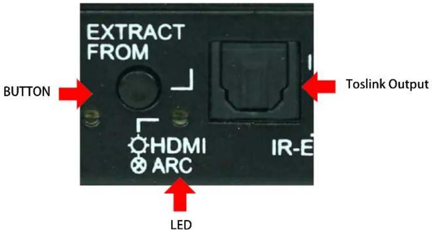
text_image
EXTRACT FROM BUTTON HDMI ARC IR-E LED Toslink OutputARC Diagram:
AUDIO RETURN CHANNEL APPLICATION

flowchart
graph TD
    A["AV Pro 2014 AC EXCA-1"] -->|TOS LINK| B["AV PRO 2014 AC EXCA-1"]
    B --> C["AV PRO 2014 AC EXCA-1"]
    C --> D["AV PRO 2014 AC EXCA-1"]
    D --> E["AV PRO 2014 AC EXCA-1"]
    E --> F["AV PRO 2014 AC EXCA-1"]
    F --> G["AV PRO 2014 AC EXCA-1"]
    G --> H["AV PRO 2014 AC EXCA-1"]
    H --> I["AV PRO 2014 AC EXCA-1"]
    I --> J["AV PRO 2014 AC EXCA-1"]
    J --> K["AV PRO 2014 AC EXCA-1"]
    K --> L["AV PRO 2014 AC EXCA-1"]
    L --> M["AV PRO 2014 AC EXCA-1"]
    M --> N["AV PRO 2014 AC EXCA-1"]
    N --> O["AV PRO 2014 AC EXCA-1"]
    O --> P["AV PRO 2014 AC EXCA-1"]
    P --> Q["AV PRO 2014 AC EXCA-1"]
    Q --> R["AV PRO 2014 AC EXCA-1"]
    R --> S["AV PRO 2014 AC EXCA-1"]
    S --> T["AV PRO 2014 AC EXCA-1"]
    T --> U["AV PRO 2014 AC EXCA-1"]
    U --> V["AV PRO 2014 AC EXCA-1"]
    V --> W["AV PRO 2014 AC EXCA-1"]
    W --> X["AV PRO 2014 AC EXCA-1"]
    X --> Y["AV PRO 2014 AC EXCA-1"]
    Y --> Z["AV PRO 2014 AC EXCA-1"]
    Z --> AA["AV PRO 2014 AC EXCA-1"]
    AA --> AB["AV PRO 2014 AC EXCA-1"]
    AB --> AC["AV PRO 2014 AC EXCA-1"]
    AC --> AD["AV PRO 2014 AC EXCA-1"]
    AD --> AE["AV PRO 2014 AC EXCA-1"]
    AE --> AF["AV PRO 2014 AC EXCA-1"]
    AF --> AG["AV PRO 2014 AC EXCA-1"]
    AG --> AH["AV PRO 2014 AC EXCA-1"]
    AH --> AI["AV PRO 2014 AC EXCA-1"]
    AI --> AJ["AV PRO 2014 AC EXCA-1"]
    AJ --> AK["AV PRO 2014 AC EXCA-1"]
    AK --> AL["AV PRO 2014 AC EXCA-1"]
    AL --> AM["AV PRO 2014 AC EXCA-1"]
    AM --> AN["AV PRO 2014 AC EXCA-1"]
    AN --> AO["AV PRO 2014 AC EXCA-1"]
    AO --> AP["AV PRO 2014 AC EXCA-1"]
    AP --> AQ["AV PRO 2014 AC EXCA-1"]
    AQ --> AR["AV PRO 2014 AC EXCA-1"]
    AR --> AS["AV PRO 2014 AC EXCA-1"]
    AS --> AT["AV PRO 2014 AC EXCA-1"]
    AT --> AU["AV PRO 2014 AC EXCA-1"]
    AU --> AV["AV PRO 2014 AC EXCA-1"]
    AV --> AW["AV PRO 2014 AC EXCA-1"]
    AW --> AX["AV PRO 2014 AC EXCA-1"]
    AX --> AY["AV PRO 2014 AC EXCA-1"]
    AY --> AZ["AV PRO 2014 AC EXCA-1"]
    AZ --> BA["AV PRO 2014 AC EXCA-1"]
    BA --> BB["AV PRO 2014 AC EXCA-1"]
    BB --> BC["AV PRO 2014 AC EXCA-1"]
    BC --> BD["AV PRO 2014 AC EXCA-1"]
    BD --> BE["AV PRO 2014 AC EXCA-1"]
    BE --> BF["AV PRO 2014 AC EXCA-1"]
    BF --> BG["AV PRO 2014 AC EXCA-1"]
    BG --> BH["AV PRO 2014 AC EXCA-1"]
    BH --> BI["AV PRO 2014 AC EXCA-1"]
    BI --> BJ["AV PRO 2014 AC EXCA-1"]
    BJ --> BK["AV PRO 2014 AC EXCA-1"]
    BK --> BL["AV PRO 2014 AC EXCA-1"]
    BL --> BM["AV PRO 2014 AC EXCA-1"]
    BM --> BN["AV PRO 2014 AC EXCA-1"]
    BN --> BO["AV PRO 2014 AC EXCA-1"]
    BO --> BP["AV PRO 2014 AC EXCA-1"]
    BP --> BQ["AV PRO 2014 AC EXCA-1"]
    BQ --> BR["AV PRO 2014 AC EXCA-1"]
    BR --> BS["AV PRO 2014 AC EXCA-1"]
    BS --> BT["AV PRO 2014 AC EXCA-1"]
    BT --> BU["AV PRO 2014 AC EXCA-1"]
    BU --> BV["AV PRO 2014 AC EXCA-1"]
    BV --> BW["AV PRO 2014 AC EXCA-1"]
    BW --> BX["AV PRO 2014 AC EXCA-1"]
    BX --> BY["AV PRO 2014 AC EXCA-1"]
    BY --> BZ["AV PRO 2014 AC EXCA-1"]
    BZ --> CA["AV PRO 2014 AC EXCA-1"]
    CA --> CB["AV PRO 2014 AC EXCA-1"]
    CB --> CC["AV PRO 2014 AC EXCA-1"]
    CC --> CD["AV PRO 2014 AC EXCA-1"]
    CD --> CE["AV PRO 2014 AC EXCA-1"]
    CE --> CF["AV PRO 2014 AC EXCA-1"]
    CF --> CG["AV PRO 2014 AC EXCA-1"]
    CG --> CH["AV PRO 2014 AC EXCA-1"]
    CH --> CI["AV PRO 2014 AC EXCA-1"]
    CI --> CJ["AV PRO 2014 AC EXCA-1"]
    CJ --> CK["AV PRO 2014 AC EXCA-1"]
DELIVER AUDIO FROM THE DISPLAY INTO YOUR AVR OR AUDIO DISTRIBUTION SYSTEM
■ The Receiver

text_image
USB SETTING TEST Spole IN Select BI DIR SFP AVPro edge AC-EXO-444-R 300m/1000ft@4K 60 4:4:4 & HDR, MM Fiber 2000m/7000ft@4K 60 4:4:4 & HDR, SM Fiber Bidirectional Single Fiber Optical Extender with 2-Way IR & RS232 including AUDIO INJECTION, EXTRACTION & ARC 4K ADVANCED ULTRA HD RECEIVER HDMI OUT RS232 IR IN IR OUT 48V
text_image
Back IR In IR Out HDMI IN RS232 + HDMI STATUS TX RX IR 48V HDMI In RS232 (COM & Pass-through) 48V
text_image
Front ARC Select SETTING PATTERN AUDIO TEST SELECT USB ISP/CTL SPDIF ARC SINGLE FIBER Toslink (IN) Single LC SFP Fiber InputIndicator Troubleshooting Lights on the Receiver:
POWER - On the front (Setting Light): (Red) the setting light doubles as the POWER indicator. 'This is an indicator that the power is connected. There are only two states for light:
• Light Is On = Power supply is connected and functioning.
- Light Is Off = Power supply is not connected or there is no power present. (In order to have power: check the power supply, USP, Outlet, etc...)
HDMI STATUS - On the back (By HDMI Port): (Red) This indicator shows that the HDMI Sink is connected. The states are:
• Light Is On (Solid) = Sync w/ HDMI sink is correct and solid.
- Light Is Flashing = The light flashes during the sync process. If it is flashing continuously, you may still have a picture, but it is indicating that the Rx is correcting a BE (Bit Error) to make the picture show on the display.
- Light Is Off = HDMI is not communicating - Please check the cables.
If the RED HDMI SIGNAL STATUS LIGHT is flashing or off AND you have no picture, check the following:
- The source. Plug it directly into the display to be sure it's functioning properly.
- Try a longer HDMI cable. Some HDMI cables do not sync well at shorter lengths.
- If these suggestions do not work, enable the "Test Pattern" (See Below). If you see the pattern, the problem is between the Receiver and display/sink please try a different sink input or HDMI cable.
- Contact AVProEdge if these suggestions do not work.
Functions & Setup of the Receiver:
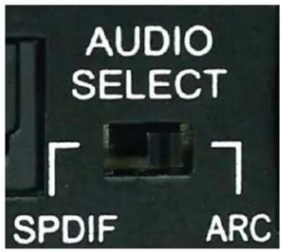
Audio Select Slide Switch: (On Front) This is used to select where ARC will come from There are two modes:
- ARC (Default) - The audio sent back to the transmitter will be from the HDMI Audio Return Channel. The supported formats are 2CH PCM, 6CH/7CH LPCM, DTS 5.1, Dolby Digital, Dolby Digital Plus. No down-mix, pass through only. Please see the AC-ADM-COTO for down-mixing.
- In this mode the SPDIF Input is inactive.
To use ARC via HDMI, make sure ARC in enabled on on AVR and Display properly.
○ The SPDIF Out on the transmitter will be active for up to DD+ - Dolby Atmos can pass over HDMI ARC
- SPDIF (Recommended) - The audio sent back to the transmitter will be from the SPDIF input. The supported formats are 2CH PCM, 6CH/7CH LPCM, DTS 5.1, Dolby Digital, Dolby Digital Plus. No down-mix, pass through only. Please see the AC-ADM-COTO for down-mixing.
NOTE - On the Tx, you can retrieve the signal from HDMI or SPDIF Toslink
text_image
AUDIO SELECT SPDIF ARCUsing the Pattern Test Button: (On Front) This button enables the built in Test Pattern Generator
Test Pattern Generator:
Press the Pattern Test button, you should see the 1080p
color bar pattern as seen below.
LED On: 1080p test pattern being
generated LED Off: Test pattern disabled

text_image
SETTING PATTERN TEST USB ISP/CTL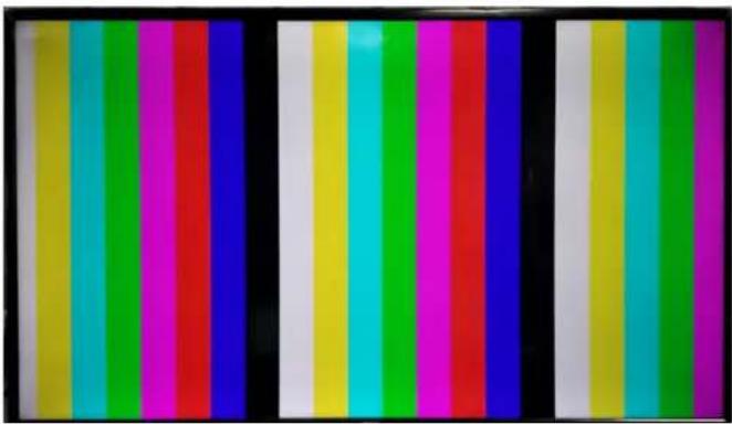
natural_image
Color test strip with multiple vertical bars of different colors (no text or symbols)Note: This can be useful for checking your cabling and for troubleshooting.
■ RS-232 Configuration
RS-232 can be used to pass control signals bi-directionally to & from any RS-232 compatible device. This is commonly used to route control signals in the following way:
- Control System --> Display/Projector (ie, Power On/Off)
- Display/Projector --> Control System (ie, Display Status, Volume Status etc...)
- When ultra long-range serial communication is needed (think concerts, live events). Use the extender.
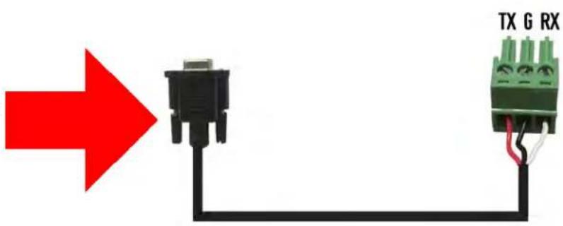
The unit comes with 3 pin connectors to allow for any wire an integrator would like.
The pin out configuration Left=TX, Center=Ground, Right=RX and looks like this:

text_image
TX ⊥ RXThis is how the cable should look. If using the AC-CABLE-3.5-DB9F (Female) or AC-CABLE-3.5-DB9M (Male), the colors will be the same. With any other cable, please follow Tx, G, Rx as shown above.
A RS-232 cable preparation diagram is on the next page.
text_image
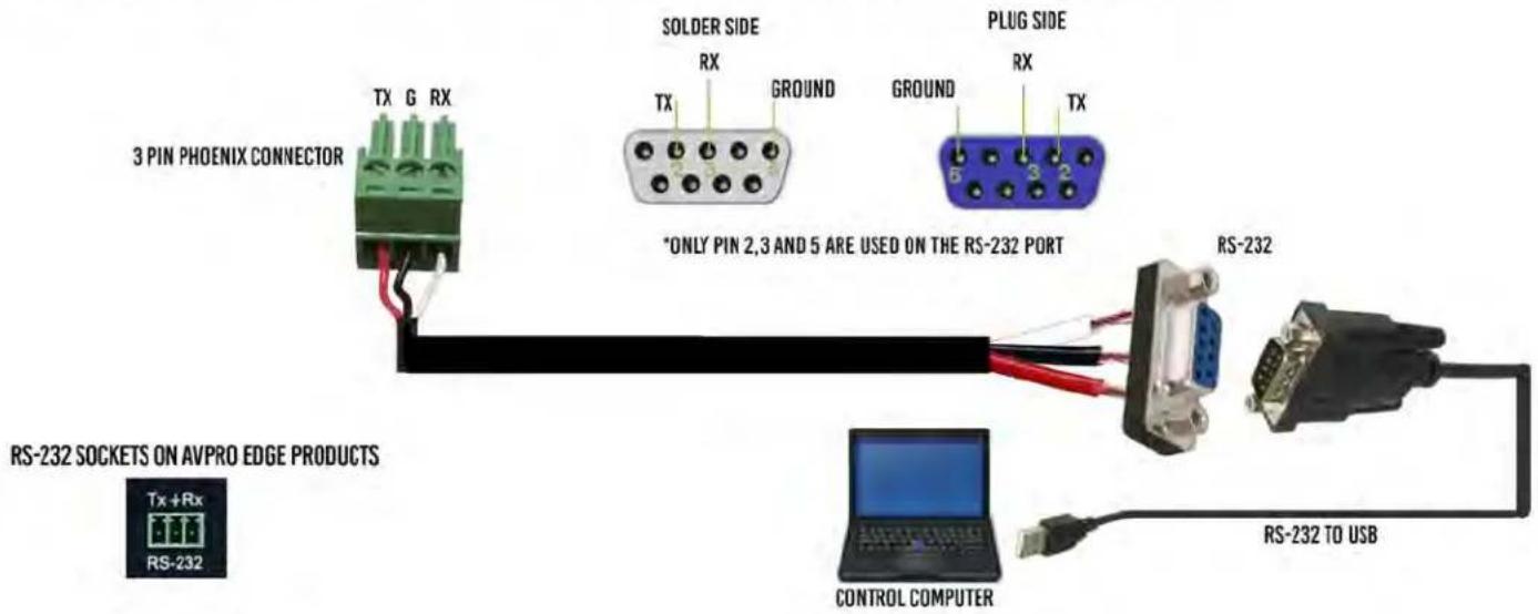
TX G RX■ RS-232 Cable Prep
RS-232 CABLE FOR AVPRO EDGE
IN ORDER TO CONNECT YOUR COMPTER TO THE SWITCH BY RS-232 YOU NEED TO MAKE YOUR OWN CABLE WITH ONE END A PHOENIX CONNECTOR AND THE OTHER END A RS-232 PORT. YOUR COMPUTER DOESN'T HAVE A RS-232 INPUT, GET A USB CONVERTER (AS SHOWN BELOW), AND PLUG THE USB END TO ANY COMPUTER
text_image
3 PIN PHOENIX CONNECTOR TX G RX SOLDER SIDE RX GROUND PLUG SIDE TX *ONLY PIN 2,3 AND 5 ARE USED ON THE RS-232 PORT RS-232 RS-232 TO USB RS-232 SOCKETS ON AVPRO EDGE PRODUCTS Tx +Rx RS-232 CONTROL COMPUTER■ RS-232 Sample Application

Pro edge
AC-EXO-444-KIT
RS-232 CONTROL

flowchart
graph LR
    A["CONTROL PROCESSOR"] --> B["4K Ultraloid Transmitter"]
    B --> C["4K Ultraloid Receiver"]
    C --> D["DISPLAY / PROJECTOR"]
RS-232 CONTROL IS BI-DIRECTIONAL SO YOU ARE ABLE TO RECEIVE FEEDBACK
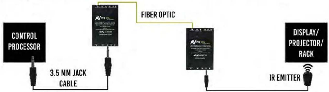
■ IR Configuration
IR can be used in three ways:
- From Rack (Control System Direct): Plug a MONO 3.5mm cable into an emitter port of any control system directly into the "IR IN" port on the AC-EXO-444 Transmitter to pass IR signals directly to the remote end. NOTE - Be sure the IR MODE Slide Switch is set to "I-PASS" on the Transmitter
- From Rack (Using IR-EYE): Plug an IR-Receiver Eye into the "IR IN" of the AC-EXO-444 Transmitter in order to pass infrared signals generated from a device or IR Remote. NOTE - Be sure the IR MODE Slide Switch is set to "IR-EYE" on the Transmitter.
- From Remote End: Use an IR-Receiver Eye on the AC-EXO-444 Receiver (IR In Port) in order to send IR signals BACK to the rack and out of the TRANSMITTER IR Out Port with an emitter.
AVPro edge AC-EXO-444-KIT
I-PASS IR CONTROL
flowchart
graph LR
    A["CONTROL PROCESSOR"] -->|3.5 MM JACK CABLE| B["4K Computer"]
    B --> C["FIBER OPTIC"]
    C --> D["4K Computer"]
    D --> E["IR EMITTER"]
    E --> F["DISPLAY/PROJECTOR/RACK"]

flowchart
graph LR
    A["IR EYE"] -->|3.5 MM JACK CABLE| B["TRANSMITTER"]
    B -->|CAT 5/6/7| C["TRANSMITTER"]
    C --> D["DISPLAY/PROJECTOR/RACK"]
    D --> E["IR EMITTER"]
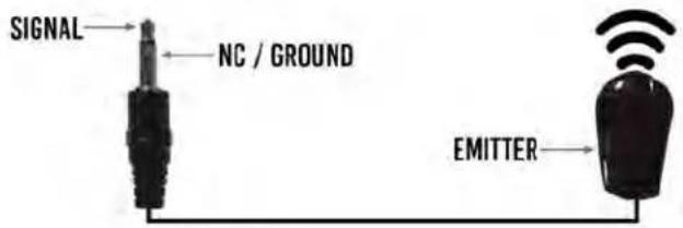
■ IR Connections to AC-EXO-444-T (Transmitter)
IR IN Direct Connect (I-PASS)

text_image
SIGNAL NC / GROUND TO CONTROL SYSTEM 3.5MN MONO CABLEIR OUT Emitter (Non-Flashing)
text_image
SIGNAL NC / GROUND EMITTERIR IN w/ Receiver Eye ("IR-EYE" MODE)
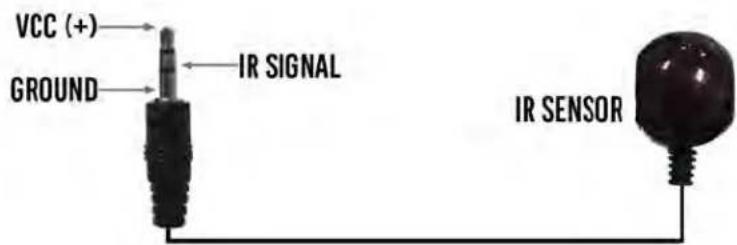
text_image
VCC (+) GROUND IR SIGNAL IR SENSOR■ IR Connections to AC-EXO-444-R (Receiver)
IR IN (IR-EYE Only)

text_image
VCC (+) GROUND IR SIGNAL IR SENSORIR OUT Emitter (Non-Flashing)

text_image
SIGNAL NC / GROUND EMITTER- Maintenance
To ensure reliable operation of this product as well as protecting the safety of any person using or handling this device while powered, please observe the following instructions.
- Use the power supplies provided. If an alternate supply is required, check voltage, polarity and that it has sufficient power to supply the device it is connected to.
- Do not operate these products outside the specified temperature and humidity range given in the above specifications.
- Ensure there is adequate ventilation to allow this product to operate efficiently.
- Repair of the equipment should only be carried out by qualified professionals as these products contain sensitive components that may be damaged by any mistreatment.
- Only use this product in a dry environment. Do not allow any liquids or harmful chemicals to come into contact with these products.
- Clean this unit with a soft, dry cloth. Never use alcohol, paint thinner or benzene to clean this unit.
- Damage Requiring Service
The unit should be serviced by qualified service personnel if:
• The DC power supply cord or AC adaptor has been damaged
- Objects or liquids have gotten into the unit
• The unit has been exposed to rain
- The unit does not operate normally or exhibits a marked change in performance
• The unit has been dropped or the housing damaged
■ Support
Should you experience any problems while using this product, first, refer to the Troubleshooting section of this manual before contacting Technical Support. When calling, the following information should be provided:
• Product name and model number
• Product serial number
- Details of the issue and any conditions under which the issue is occurring
Warranty
If your product does not work properly because of a defect in materials or workmanship, AVProEdge (referred to as “the warrantor”) will, for the length of the period indicated as below, (Parts/Labor (10) Years), which starts with the date of original purchase (“Limited Warranty period”), at its option either (a) repair your product with new or refurbished parts, or (b) replace it with a new or a refurbished product. The decision to repair or replace will be made by the warrantor. During the “Labor” Limited Warranty period there will be no charge for labor. During the “Parts” warranty period, there will be no charge for parts. You must mail-in your product during the warranty period. This Limited Warranty is extended only to the original purchaser and only covers product purchased as new. A purchase receipt or other proof of original purchase date is required for Limited Warranty service.
This warranty extends to products purchased directly from AVPro or an authorized dealer. AVPro is not liable to honor this warranty if the product has been used in any application other than that for which it was intended, has been subjected to misuse, accidental damage, modification or improper installation procedures, unauthorized repairs or is outside of the warranty period. Please direct any questions or issues you may have to your local dealer before contacting AVPro.
- Troubleshooting
- Verify Power - Transmitter Pg.5 Receiver Pg.8
- Note: Must power from both sides
- Verify Connections - Check that all cables are properly connected
。TX Indicator Troubleshooting Lights - Pg.5
。RX Indicator Troubleshooting Lights - Pg.8
- Not passing video - You can use the built in Test Pattern Generator to verify signal from the TX to the Display Pg.9
• Extracted Audio Issues - Verify audio settings - Transmitter Pg.7 Receiver Pg.8
- IR Issues - Verify correct connections and settings - P.12 & 13
Note: Visibly flashing Emitters may not function properly, try the IR Cables that come with the kit
• Still having issues, contact us
o Support Direct - +1-605-977-3477
+1-605-274-6055
- Submit a support request ticket
https://support.avproedge.com/hc/en-us/requests/new
Thank you for choosing AVProEdge!
Please contact us with any questions. We are happy to be of service!
AV Pro edge
CE

RoHS
AVProEdge
2222 E 52nd St N\~ Sioux Falls, SD 57104
1-877-886-5112\~605-274-6055
support@avproedge.com