GV-NET IO CARD V3.2 - Expansion card Geovision - Free user manual and instructions
Find the device manual for free GV-NET IO CARD V3.2 Geovision in PDF.

User questions about GV-NET IO CARD V3.2 Geovision
0 question about this device. Answer the ones you know or ask your own.
Ask a new question about this device
Download the instructions for your Expansion card in PDF format for free! Find your manual GV-NET IO CARD V3.2 - Geovision and take your electronic device back in hand. On this page are published all the documents necessary for the use of your device. GV-NET IO CARD V3.2 by Geovision.
USER MANUAL GV-NET IO CARD V3.2 Geovision
The GV-NET/IO Card is a RS-485 / RS-232 interface converter, and provides 4 inputs and 4 relay outputs as well. It supports both DC and AC output voltages.
Key Features
- A USB port is provided for PC connection, and it is used with 30 DC output voltages.
- It can switch between two modes, NET/IO Card Mode and I/O Box Mode, which expand its capability.
- Up to 4 GV-NET/IO Cards can be chained together when it is on the I/O Box Mode.
- It can act as an independent device when it is on the I/O Box Mode.
System Requirements
If the GV-NET/IO Card is listed as Prolific USB-to-Serial Comm Port under Windows Device Manager, GV-System version 8.2 or above is required. If the GV-NET/IO Card is listed as XR21B1411 USB UART under Windows Device Manager, GV-System version 8.5.7.0 or above is required.
To see how to check the device name under Windows Device Manager, refer to Installing USB Driver later in this Installation Guide.
Packing List
- GV-NET/IO Card x 1
- 20-Pin Ribbon Cable with 4 Connectors x1
- RJ-11 to DB9 Cable x 1
- RJ-11 to USB Cable x 1
- 3-Pin Internal USB Cable x 1
- 4-Pin to 4-Pin Mini Power Cable x 1
- Installation Guide x 1
- Software DVD x 1
Overview
text_image
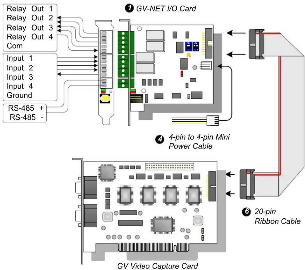
Relay Out 1 Relay Out 2 Relay Out 3 Relay Out 4 Com Input 1 Input 2 Input 3 Input 4 Ground RS-485 + RS-485 - ① GV-NET I/O Card ④ 4-pin to 4-pin Mini Power Cable ⑥ 20-pin Ribbon Cable GV Video Capture CardGV-NET/IO Card connections
Note:
- The supplied RJ-11 to DB9 Cable of older versions is not compatible with the GV-NET/IO Card V3.1 or later.

text_image
Version 3.1 or later With a PC Mark PC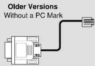
text_image
Older Versions Without a PC Mark- When the GV-NET/IO Card V3.1 or later is in the I/O Box mode, it is incompatible with the GV-IO 12-In Card of versions earlier than V3.
-
To prevent the noise interference in I/O operation, tightly screw the GV-NET/IO Card V3.1 or later to the PC case.
-
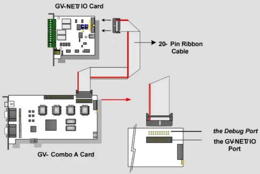
Ensure to connect the GV-NET/IO Card to the 20-pin GV-NET/IO port on the GV-Combo A Card as illustrated below. Wrong connection may damage the GV-NET/IO Card or the GV-Combo A Card, causing Video Lost or an error message of “can’t find keypro” to pop up.
flowchart
graph TD
    A["GV-NET/IO Card"] --> B["20-Pin Ribbon Cable"]
    B --> C["the Debug Port"]
    B --> D["the GV-NET/IO Port"]
    E["GV-Combo A Card"] --> F["20-Pin Ribbon Cable"]
    F --> G["the Debug Port"]
    style A fill:#f9f,stroke:#333
    style E fill:#f9f,stroke:#333
    style B fill:#ccf,stroke:#333
    style C fill:#cfc,stroke:#333
    style D fill:#cfc,stroke:#333
    style F fill:#fcc,stroke:#333
    style G fill:#fcc,stroke:#333
Connections with Two Video Capture Cards
If your system is equipped with two video capture cards, connect the GV-NET/IO Card to the video capture card of 1-16 channels.
Connections in NET/IO Card Mode
For the connections in the NET/IO Card Mode, please follow the instructions below:
- It is required to connect the GV-NET/IO Card to GV-Video Capture Card with the 20-Pin Ribbon Cable.
- If you want to connect the GV-NET/IO Card to RS-485 devices, you have three ways of connections. See below.
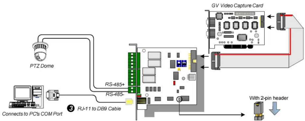
Three Ways of Connections of GV-NET/IO Card and RS-485 Devices:
- You can connect a RJ-11 to DB9 Cable to the PC's COM Port when a RS-485 device is connected. (Allowed for AC/DC Output Voltage)
flowchart
graph TD
    A["PTZ Dome"] --> B["Connects to PC's COM Port"]
    B --> C["RS-485+"]
    B --> D["RS-485-"]
    C --> E["RJ-11 to DB9 Cable"]
    D --> E
    E --> F["GV Video Capture Card"]
    F --> G["With 2-pin header"]
    G --> H["Computer"]
- You can connect a RJ-11 to USB Cable to the PC's USB Port when a RS-485 device is connected. (Allowed for AC/DC Output Voltage)

flowchart
graph TD
    A["PTZ Dome"] --> B["Connects to PC's USB Port"]
    B --> C["RS-485+"]
    B --> D["RS-485-"]
    C --> E["RJ-11 to USB Cable"]
    D --> E
    E --> F["GV Video Capture Card"]
    F --> G["With 2-pin header"]
    G --> H["Computer"]
Note: It is required to install the USB driver. For details, see Installing USB Driver later in the Installation Guide.
- You can connect a 3-Pin Internal USB Cable to the USB Connectors on the PC's Motherboard when a RS-485 device is connected. (Allowed for AC/DC Output Voltage)

flowchart
graph TD
    A["PTZ Dome"] --> B["VCC (white) DM (D-)<br>(green) DP (D+)<br>(black) GND"]
    B --> C["Connects to the USB Connectors on the PC's motherboard"]
    C --> D["3-pin Internal USB Cable"]
    D --> E["RS-485+"]
    E --> F["GSV Video Capture Card"]
    F --> G["With 2-pin header"]
    G --> H["Device with 2-pin header"]
Note: It is required to install the USB driver. For details, see Installing USB Drive later in the Installation Guide.
Connections In I/O Box Mode
For the connections in the I/O Box Mode, please follow the instructions below:
- It is not necessary to connect the GV-NET/IO Card to GV-Video Capture Card.
- Connect the GV-NET/IO Card to the PC by one of the following three ways.
Three Ways of Connections of GV-NET/IO Card and PC:
- You can connect a RJ-11 to DB9 Cable to the PC's COM Port. (Allowed for AC/DC Output Voltage)
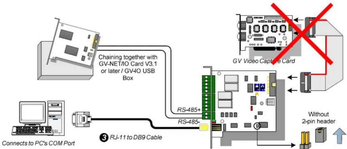
flowchart
graph TD
    A["Connects to PC's COM Port"] --> B["Computer"]
    B --> C["Chaining together with GV-NET/IO Card V3.1 or later / GV-IO USB Box"]
    C --> D["RS-485+"]
    C --> E["RS-485-"]
    D --> F["GB"]
    E --> F
    F --> G["Without 2-pin header"]
    G --> H["GB Video Capture Card"]
    style A fill:#f9f,stroke:#333
    style H fill:#bbf,stroke:#333
- You can connect a RJ-11 to USB Cable to the PC's USB Port. (Allowed for DC Output Voltage only)

flowchart
graph TD
    A["Connects to PC's USB Port"] --> B["Chaining together with GV-NET/IO Card V3.1 or later / GV-IO USB Box"]
    B --> C["RS-485+"]
    B --> D["RS-485-"]
    C --> E["GV Video Capture Card"]
    D --> E
    E --> F["Without 2-pin header"]
    style E stroke:#ff0000,stroke-width:2px
Note: It is required to install the USB driver. For details, see Installing USB Driver later in the Installation Guide.
- You can connect a 3-Pin Internal USB Cable to the USB Connectors on the PC's Motherboard. (Allowed for DC Output Voltage only)
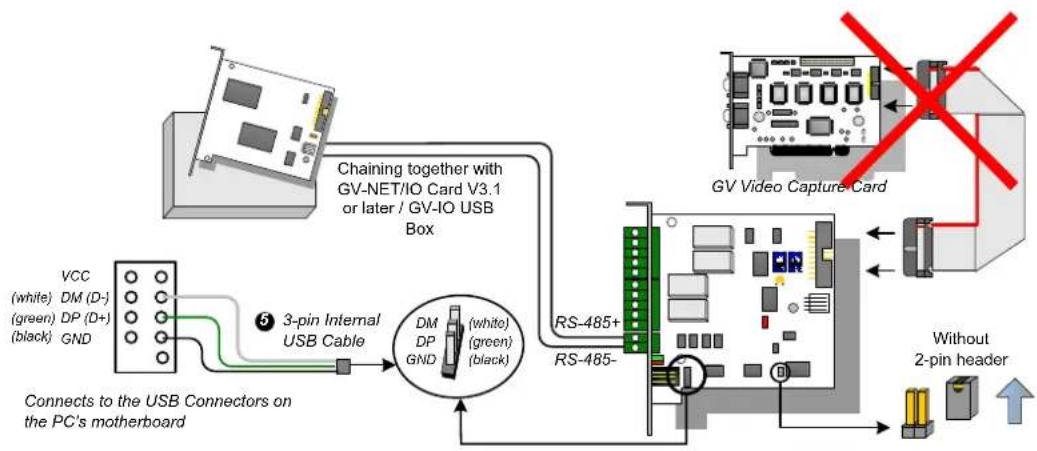
flowchart
graph TD
    A["PC Board"] -->|Chaining together with GV-NET/IO Card V3.1 or later / GV-IO USB Box| B["3-pin Internal USB Cable"]
    B --> C["Connects to the USB Connectors on the PC's motherboard"]
    C --> D["DM DP GND (white) (green) (black)"]
    D --> E["RS-485+"]
    E --> F["Without 2-pin header"]
    F --> G["RS-485-"]
    G --> H["GB"]
    style A fill:#f9f,stroke:#333
    style H fill:#ccf,stroke:#333
Note: It is required to install the USB driver. For details, see Installing USB Driver later in the Installation Guide.
Switching Modes
The GV-NET/IO Card provides two modes for users to expand its capability: I/O Box Mode and NET/IO Card Mode. With a mode-switch jumper to insert on the 2-pin header, you can switch between modes.
- NET/IO Card Mode (default): With the switch jumper inserted, this default mode acts as a GV-NET/IO Card. It is required to connect the GV-NET/IO Card to the GV-Video Capture Card for usage.
- I/O Box Mode: Without the switch jumper inserted, the GV-NET/IO Card can work as an independent device. It is NOT necessary to connect to the GV-Video Capture Card for usage.
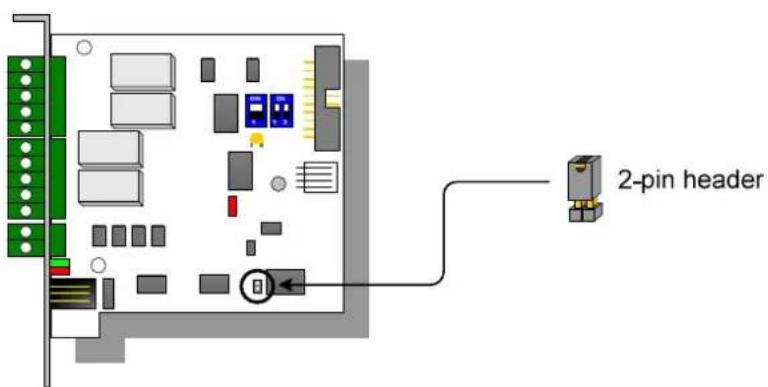
text_image
2-pin headerExtended Connections
Via the RS-485 connectors, up to 4 GV-NET/IO Cards can be chained together when the GV-NET/IO Card is on the I/O Box mode. For extended connections, the address assignment is shown below.
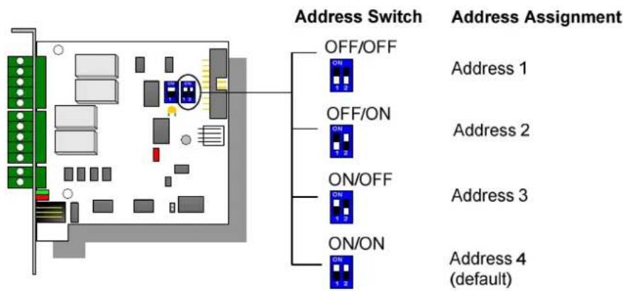
text_image
Address Switch OFF/OFF ON 1 2 Address Assignment OFF/ON ON 1 2 Address 1 Address 2 ON/OFF ON 1 2 Address 3 ON/ON ON 1 2 Address 4 (default)Note: When the GV-NET/IO Card is set to the I/O Box Mode, it can have extended connections with GV-I/O Boxes.
DIP Switch
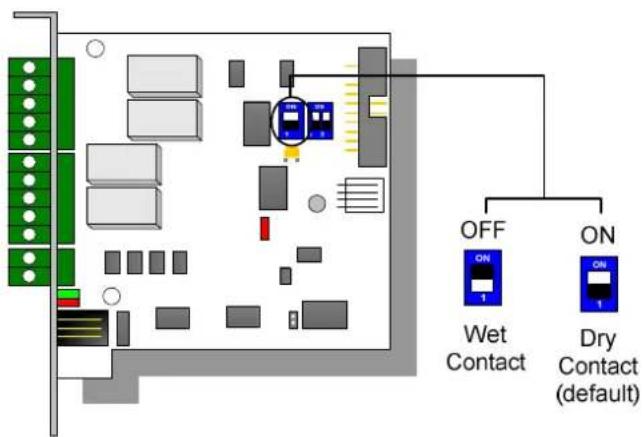
text_image
OFF ON Wet Contact Dry Contact (default)Installing USB Driver
To use the USB function, it is required to install the driver on the PC. Follow these steps to install the driver:
- Insert the software DVD. It will run automatically and pop up a window.
- Click Install GeoVision USB Devices Driver. This dialog box appears.

text_image
GeoVision USB Driver Installer Install Remove Exit- Click Install to install the drivers. When the installation is complete, this message will appear: Install Successfully.
- Click Exit to close the dialog box and restart the PC.
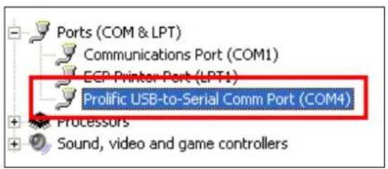
To verify the drivers are installed correctly, go to Windows Device Manager after restarting the PC. Expanding the Ports field, you should see Prolific USB-to-Serial Comm Port or XR21B1411 USB UART depending on the version of the driver. The COM number in the parenthesis indicates the COM port currently in use.
text_image
Ports (COM & LPT) Communications Port (COM1) ECP Printer Port (LPT1) Prolific USB-to-Serial Comm Port (COM4) + + + Processors Sound, video and game controllers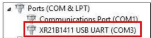
text_image
Ports (COM & LPT) Communications Port (COM1) XR21B1411 USB UART (COM3)Note: If you unplug the GV-NET/IO Card from the PC and connect another GV-Net/IO Card to the same USB port, the COM port may still be changed. Access the Windows Device Manager again to look up the new COM port number.
Specifications
| OS | 32-bit | Windows XP / Vista / 7 / 8 / Server 2008 | |
| 64-bit Windows 7 / 8 / | Server 2008 / Server 2012 | ||
| Input | Input 4 | ||
| Input Signal Dry Contact, Wet Contact 9~30V AC / DC | |||
| Output | Relay Output 4 | ||
| Relay Status Normal Open | |||
| Relay Capacitance | USB Connection 30V DC, | 3A | |
| RS-232 Connection | 125 / 250V AC, 3A30V DC, 3A | ||
| Interface | RJ-11 to DB9 | ||
| RJ-11 to USB | |||
| 3-Pin Internal USB to Internal USB | |||
| Mode Switch | I/O Box Mode Without GV-Video Capture Card | ||
| NET/IO Card Mode With GV-Video Capture Card | |||
| Address | 1~4 | ||
| Communication | RS-485, USB, RS-232 | ||
| Operating Temperature | 0°C ~50°C / 32°F ~122°F | ||
| Humidity 5% ~ 95% (Non-Condensing) | |||
| Compatible Model | All GV-Video Capture Card Models | ||
| Dimensions (W x H) | 99 x 90 mm / 3.90 x 3.54 in | ||
Ordering Information
55-IOCRD-310