EFL8550 - Remote control toy E-flite - Free user manual and instructions
Find the device manual for free EFL8550 E-flite in PDF.

| Product Type | Remote Control Toy |
| Brand | E-flite |
| Model | EFL8550 |
| Dimensions (L x W x H) | 12.2 x 7.9 x 3.9 in (310 x 200 x 100 mm) |
| Weight | 7.1 oz (201 g) |
| Power Supply - Aircraft | 3.7V 150mAh LiPo battery (included) |
| Power Supply - Transmitter | 4 x AA batteries (not included) |
| Radio Frequency | 2.4GHz |
| Control Range | Up to 300 ft (91 m) |
| Flight Time | Approximately 8-10 minutes |
| Charging Time | Approximately 60 minutes |
| Construction Material | Durable foam |
| Key Features | Ready-to-fly, 2.4GHz radio, LED lights, beginner mode |
| Maintenance | Wipe clean with a dry cloth; store in a cool, dry place |
| Safety | Keep away from water; avoid flying near people, animals, or obstacles; follow local regulations |
| Spare Parts & Repairability | Replacement propellers, batteries, and parts available from E-flite; basic repairs feasible |
| Age Recommendation | 14 years and up |
| Assembly Required | Minimal (attach propeller, install batteries) |
Frequently Asked Questions - EFL8550 E-flite
User questions about EFL8550 E-flite
0 question about this device. Answer the ones you know or ask your own.
Ask a new question about this device
Download the instructions for your Remote control toy in PDF format for free! Find your manual EFL8550 - E-flite and take your electronic device back in hand. On this page are published all the documents necessary for the use of your device. EFL8550 by E-flite.
USER MANUAL EFL8550 E-flite
natural_image
Line drawing of a vintage propeller aircraft in flight, showing detailed aerodynamic components and fan blades (no text or symbols)Instruction Manual
Bedienungsanleitung
All instructions, warranties and other collateral documents are subject to change at the sole discretion of Horizon Hobby, LLC. For up-to-date product literature, visit www.horizonhobby.com and click on the support tab for this product.
Meaning of Special Language:
The following terms are used throughout the product literature to indicate various levels of potential harm when operating this product:
NOTICE: Procedures, which if not properly followed, create a possibility of physical property damage AND little or no possibility of injury.
CAUTION: Procedures, which if not properly followed, create the probability of physical property damage AND a possibility of serious injury.
WARNING: Procedures, which if not properly followed, create the probability of property damage, collateral damage, and serious injury OR create a high probability of superficial injury.

WARNING: Read the ENTIRE instruction manual to become familiar with the features of the product before operating. Failure to operate the product correctly can result in damage to the product, personal property and cause serious injury.
This is a sophisticated hobby product. It must be operated with caution and common sense and requires some basic mechanical ability. Failure to operate this Product in a safe and responsible manner could result in injury or damage to the product or other property. This product is not intended for use by children without direct adult supervision. Do not use with incompatible components or alter this product in any way outside of the instructions provided by Horizon Hobby, LLC. This manual contains instructions for safety, operation and maintenance. It is essential to read and follow all the instructions and warnings in the manual, prior to assembly, setup or use, in order to operate correctly and avoid damage or serious injury.
14+
AGE RECOMMENDATION: Not for children under 14 years. This is not a toy.

WARNING AGAINST COUNTERFEIT PRODUCTS: If you ever need to replace your Spektrum receiver found Horizon Hobby product, always purchase from Horizon Hobby, LLC or a Horizon Hobby authorized dealer to enauthentic high-quality Spektrum product. Horizon Hobby, LLC disclaims all support and warranty with regards, not limited to, compatibility and performance of counterfeit products or products claiming compatibility with or Spektrum technology.
Safety Precautions and Warnings
As the user of this product, you are solely responsible for operating in a manner that does not endanger yourself and others or result in damage to the product or the property of others.
- Always keep a safe distance in all directions around your model to avoid collisions or injury. This model is controlled by a radio signal subject to interference from many sources outside your control. Interference can cause momentary loss of control.
- Always operate your model in open spaces away from full-size vehicles, traffic and people.
- Always carefully follow the directions and warnings for this and any optional support equipment (chargers, rechargeable battery packs, etc.).
- Always keep all chemicals, small parts and anything electrical out of the reach of children.
• Always avoid water exposure to all equipment not specifically designed and
protected for this purpose. Moisture causes damage to electronics.
- Never place any portion of the model in your mouth as it could cause serious injury or even death.
- Never operate your model with low transmitter batteries.
• Always keep aircraft in sight and under control.
• Always use fully charged batteries.
• Always keep transmitter powered on while aircraft is powered.
• Always remove batteries before disassembly.
• Always keep moving parts clean.
• Always keep parts dry.
• Always let parts cool after use before touching.
• Always remove batteries after use.
• Always ensure failsafe is properly set before fl ying.
- Never operate aircraft with damaged wiring.
- Never touch moving parts.
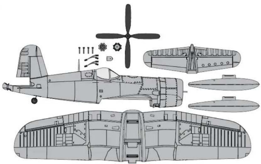
Box Contents
| Quick Start Information | |||
| Transmitter Setup | Set up your transmitter using the transmitter setup chart | ||
| Dual Rates | Hi Rate Low | Rate | |
| Ail | ▲17mm▼13mm | ▲12mm▼10mm | |
| Ele | 18mm | 13mm | |
| Rud | 18mm 14mm | ||
| Flaps | Landing▼=30mm | Takeoff▼=15mm | |
| Center of Gravity (CG) | 73mm +/- 3 back from leading edge of wing at the fuselage. | ||
| Flight Timer Setting | 5 minutes | ||
natural_image
Technical line drawing of an early propeller aircraft showing internal components and structural details (no text or labels)Specifications
| BNF BASIC | ||
 | Motor: BL15 Brushless Outrunner 850Kv (EFLM4115) | Installed |
 | ESC: 40 AMP Brushless ESC (EFLA1140W) | Installed |
 | 9 gram servo (SPMSA330) Installed | |
 | Receiver: SpektrumTM AR636A 6-Channel Sport Receiver (SMPAR636) | Installed |
 | Recommended Battery: 11.1V 3S 2200mAh 30C Li-Po (EFLB22003S30) | Required to Complete |
 | Recommended Battery Charger: 3-cell Li-Po battery balancing charger | Required to Complete |
 | Recommended Transmitter: Full-Range 6 channel (or more) 2.4GHz with Spektrum DSM2®/DSMX® technology with adjustable Dual Rates. | Required to Complete |
text_image
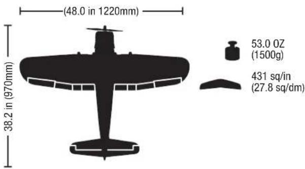
(48.0 in 1220mm) 38.2 in (970mm) 53.0 OZ (1500g) 431 sq/in (27.8 sq/dm)Table of Contents
Prefl ight ....4
Transmitter Setup 4
Model Assembly 5
Model Assembly Continued....6
Model Assembly Continued....7
Control Horn and Servo Arm Settings ....7
Optional Drop Tank Installation 8
Transmitter and Receiver Binding 8
Battery Installation and ESC Arming 9
Center of Gravity (CG) 10
AS3X Control Direction Test 10
In Flight Trimming 11
Flying Tips and Repairs ....11
Post Flight 12
Motor Service 12
Troubleshooting Guide AS3X 12
Troubleshooting Guide ....13
AMA National Model Aircraft Safety Code 14
Limited Warranty 15
Contact Information 16
FCC Information 16
IC Information 16
Compliance Information for the European Union 16
Replacement Parts 59
Optional Parts 59
To register your product online, visit www.e-fl iterc.com
Prefl ight
| 1 Remove and inspect contents. |
| 2 Read this instruction manual thoroughly. |
| 3 Charge the fl ight battery. |
| 4 Setup Transmitter using transmitter setup chart. |
| 5 Fully assemble the airplane. |
| 6 Install the fl ight battery in the aircraft (once it has been fully charged). |
| 7 Check the Center of Gravity (CG). |
| 8 Bind the aircraft to your transmitter. |
| 9 Make sure linkages move freely. |
| 10 | Test the retract operation. |
| 11 | Test the fl ap operation. |
| 12 | Perform the Control Direction Test with the transmitter. |
| 13 | Perform the AS3X Control Direction Test with the aircraft. |
| 14 | Adjust fl ight controls and transmitter. |
| 15 | Perform a radio system Range Test. |
| 16 | Find a safe open area to fl y. |
| 17 | Plan fl ight for fl ying fi eld conditions. |
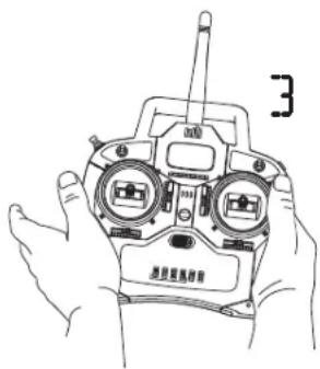
Transmitter Setup
IMPORTANT: After you set up your model, always rebind the transmitter and receiver to set the desired failsafe positions.
Dual Rates
Take first flights in Low Rate. For landings, use high rate elevator.
NOTICE: To ensure AS3X® technology functions properly, do not lower rate values below 50%. If lower rates are desired, manually adjust the position of the pushrods on the servo arm.
NOTICE: If oscillation occurs at high speed, refer to the Troubleshooting Guide for more information.
Expo
After first lights, you may adjust expo in your transmitter or refer to the AR636 receiver manual for expo adjustment.
| Computerized Transmitter Setup(DX6i, DX6, DX7, DX7S, DX8, DX9, DX10t and DX18) | ||
| Start all transmitter programming with a blank ACRO model (do a model reset), then name the model. | ||
| Set Dual Rates to: | HIGH 100% | |
| LOW 70% | ||
| Set Servo Travel to: 100% | ||
| DX6i | 1. Go to the SETUP LIST MENU | |
| 2. Set MODEL TYPE: ACRO | ||
| 3. Go to ADJUST LIST MENU | ||
| 4. Set FLAPS: Norm ↓100 FlapLAND ↑60 Flap | ||
| DX7SDX8 | 1. Go to the SYSTEM SETUP | |
| 2. Set MODEL TYPE: AIRPLANE | ||
| 3. Set WING TYPE: 1 AIL 1 FLAP | ||
| 4. Go to the FUNCTION LIST | ||
| 5. Set SERVO SETUP: Reverse GEAR | ||
| 6. Set FLAP SYSTEM: Choose FlapNORM: -100% FLAPMID: -30% FLAPLAND: 60% FLAPSPEED 2.0S: SWITCH = FLAP | ||
| DX6DX7DX9DX10tDX18 | 1. Go to the SYSTEM SETUP | |
| 2. Set MODEL TYPE: AIRPLANE | ||
| 3. Set AICRAFT TYPE:WING: 1 AIL 1 FLAP | ||
| 4. Go to the FUNCTION LIST | ||
| 5. Set SERVO SETUP: Reverse GEAR | ||
| 6. Set FLAP SYSTEM:SELECT SWITCH D:POS 0: -100% FLAPPOS 1: -30% FLAPPOS 2: 60% FLAPSPEED 2.0 | ||
Model Assembly
Horizontal Tail Installation
- Slide the horizontal tail (A) into the slot in the rear of the fuselage. Ensure the control horn faces down.
- Secure the horizontal tail piece in place using the included screw (B). Use caution to avoid over-tightening the screw.
- Attach the clevis to the elevator control horn (see instructions for clevis connection).

natural_image
Technical illustration of a helicopter's wing structure with labeled component A (no text or symbols beyond label)
text_image
B 1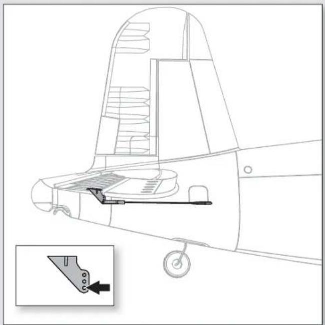
natural_image
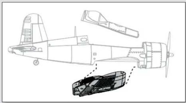
Technical line drawing of a vehicle interior with a highlighted component and an inset showing a tool (no text or symbols)Model Assembly Continued
Wing Installation
- Remove the canopy hatch.
- Guide the Flaps, Retracts and Aileron servo connectors (A) through the hole (B) located in the bottom of the fuselage as shown.
Tip: If needed, use hemostats or pliers to pull the servo connectors into the fuselage.
- Connect the Flaps, Retracts and Aileron connectors to respective Y-harnesses connected to the receiver. The left and right servos can be connected to either side of a Y-harness.
IMPORTANT: The ailerons must be connected to the receiver's AILE (#2 channel) with a Y-harness (included) for the AS3X® system to function properly.
- Align the wing with the fuselage and secure into position using the included 4 screws (C).

CAUTION: DO NOT crush or otherwise damage the wiring when winging the wing to the fuselage.
- Reinstall the canopy hatch on the fuselage.
Disassemble in reverse order.
natural_image
Technical line drawing of a multi-engine aircraft with internal components and structural details (no text or symbols)
text_image
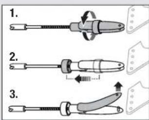
C B A Flaps Gear AileronsClevis Installation
• Pull the tube from the clevis to the linkage.
- Carefully spread the clevis, then insert the clevis pin into the desired hole in the control horn.
- Move the tube to hold the clevis on the control horn.
text_image
1. 2. 3.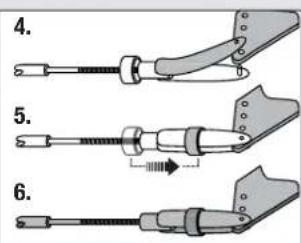
text_image
4. 5. 6.Control Surface Centering
After assembly and transmitter setup, confi rm that the control surfaces are centered. If the control surfaces are not centered, mechanically center the control surfaces by adjusting the linkages.
If adjustment is required, turn the clevis on the linkage to change the length of the linkage between the servo arm and the control horn.
After binding a transmitter to the aircraft receiver, set the trims and sub-trims to 0, then adjust the clevises to center the control surfaces.
natural_image
Pure technical line drawing of a mechanical device with no text or symbolsModel Assembly Continued
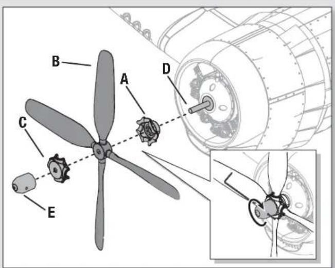
Propeller Installation
IMPORTANT: It is recommended to install the propeller after all system setups are completed to reduce the chance of accidental propeller strike.
- Install back side of propeller hub (A), propeller (B), and front side propeller hub (C) onto the motor shaft (D). The propeller size numbers (10.5 x 8) must face out from the motor for correct propeller operation.
- Install the spinner nut (E) to secure the propeller into place. Use a small screw driver or hex wrench inserted into the small hole (Inset) and turn clockwise to secure it into place.
text_image
Technical diagram of a propeller assembly with labeled parts A, B, C, D, and E, including a close-up inset showing internal components.Control Horn and Servo Arm Settings
The table to the right shows the factory settings for the control horns and servo arms. Fly the aircraft at factory settings before making changes.
NOTICE: If control throws are changed from the factory settings, the AR636 gain values may need to be adjusted. Refer to the Spektrum AR636 manual for adjustment of gain values.
After fl ying, you may choose to adjust the linkage positions for the desired control response. See the table to the right.
| Horns Arms | ||
| Elevator | 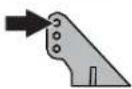 |  |
| Ailerons |  |  |
| Flaps |  |  |
| Rudder |  |  |
More control throw Less control throw
text_image
Diagram showing four different mechanical or electrical configurations with arrows indicating motion or force direction.Optional Drop Tank Installation
Drop Tank
Slide the optional drop tanks (A) into the rails (B) on each wing.
Check the Center of Gravity with the drop tanks installed.
See the Adjusting the Center of Gravity instructions for more information.
text_image
A BTransmitter and Receiver Binding
This product requires an approved Spektrum ^® DSM2 ^® /DSMX ^® compatible transmitter. Visit www.bindnfl y.com for a complete list of approved transmitters.
IMPORTANT: Before binding a transmitter, read the Transmitter Setup section of this manual to ensure that your transmitter is properly programmed for this aircraft.
Binding Procedure
| IMPORTANT: The included AR636 receiver has been programmed for operation specifi cally for this aircraft. Refer to the receiver manual for correct setup if the receiver is replaced or is used in another aircraft. | |
| CAUTION: When using a Futaba® transmitter with a Spektrum DSM module, you must reverse the throttle channel and rebind. Refer to your Spektrum module manual for binding and failsafe instructions. Refer to your Futaba transmitter manual for instructions on reversing the throttle channel. | |
| 1. Make sure the transmitter is powered off. | |
| 2. Move the transmitter controls to neutral (fl ight controls: rudder, elevators and ailerons) or to low positions (throttle, throttle trim).* | |
| 3. Install a bind plug in the receiver bind port. | |
| 4. Connect the fl ight battery to the ESC. The ESC will produce a series of sounds. One long tone, then 3 short tones confi rm that the LVC is set correctly for the ESC. The orange bind LED on the receiver will begin to fl ash rapidly. | |
| 5. Take 3 steps away from the aircraft /receiver and then power on the transmitter while holding the transmitter bind button or switch. Refer to your transmitter's manual for specifi c binding instructions.Tip: Do not to point the transmitter's antenna directly at the receiver while binding.Tip: Keep away from large metal objects while binding. | |
| 6. The receiver is bound to the transmitter when the orange bind light on the receiver stays orange. The ESC will also produce a series of three ascending tones. The tones indicate the ESC is armed, provided the throttle stick and throttle trim are low enough to trigger arming. | |
- Remove the bind plug from the bind port.
Tip: Safely store the bind plug (some owners attach the bind plug to their transmitter using two-part loops and clips).
Once bound, the receiver and transmitter should retain their bind for future f lights, even when power is cycled on and off. However, if you notice that bound has been lost, simply repeat the binding process.
The throttle will not arm if the transmitter's throttle control is not put at the lowest position. If you encounter problems, follow the binding instructions and refer to the transmitter troubleshooting guide for other instructions. If needed, contact the appropriate Horizon Product Support offi ce.
\*\*Failsafe
If the receiver loses transmitter communication, the failsafe will activate. When activated, failsafe moves the throttle channel to its preset failsafe position (low throttle) that was set during binding. All other channels hold their last position.
Bind Plug Installation
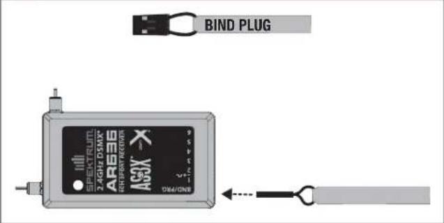
text_image
BIND PLUG AR636 ASOX 2 HIGH DRUM SPEED PLUM 2 HIGH DRUM 1 HIGH DRUM USB/ONBBattery Installation and ESC Arming
Battery Selection
We recommend the E-fl ite® 2200mAh 11.1V 3S 30C Li-Po battery (EFLB22003S30). Refer to the Optional Parts List for other recommended batteries. If using a battery other than those listed, the battery should be within the range of capacity, dimensions and weight of the E-fl ite Li-Po battery packs to fit in the fuselage. Be sure the model balances at the recommended CG.
- Lower the throttle and throttle trim to the lowest settings. Power on the Transmitter, then wait 5 seconds.
- Carefully lift the back of the canopy hatch (A) to remove.
- For added security, apply the loop side (soft side) of the optional hook and loop tape (B) to the bottom of your battery, and the hook side to the battery tray.
- Install the fully charged battery (C) all the way to the front of the battery compartment as shown. Secure using the hook and loop straps (D).
- Connect the battery to the ESC (the ESC is now armed).
- Keep the aircraft immobile and away from wind or the system will not initialize.
- The ESC will sound a series of tones (refer to step 6 of the binding instructions for more information).
- An LED will light on the receiver.
If the ESC sounds a continuous double beep after the flight battery is connected, recharge or replace the battery.
- Reinstall the canopy hatch.

text_image
Technical diagram showing a mechanical component with labeled parts and directional arrows, including section A.
text_image
B Optional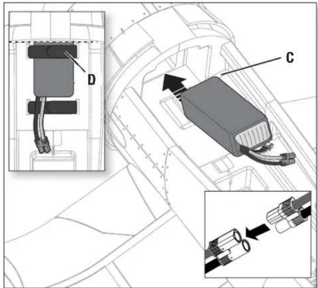
text_image
Technical diagram showing component assembly with labeled parts D and C, including a close-up of connector detail
natural_image
Illustration of a vintage military aircraft with visible fuselage, tail rotor, and signal waves (no text or symbols)CAUTION: Always keep hands away from the propeller. When armed, the motor will turn the propeller in response to any throttle movement.
Center of Gravity (CG)
The CG location is measured from the leading edge of the wing at the root. This CG location has been determined with the recommended Li-Po battery (EFLB22003S30) installed to the front edge of the battery tray.
Tip: Measure the CG with the aircraft inverted.

text_image
73mm +/-3 back from leading edge ing edge of wing at the fuselage.AS3X Control Direction Test
This test ensures that the AS3X ^® control system is functioning properly. Assemble the aircraft and bind your transmitter to the receiver before performing this test.
- Raise the throttle just above 25%, then lower the throttle to activate AS3X technology.

CAUTION: Keep all body parts, hair and loose clothing away from a moving propeller, as these items could become entangled.
IMPORTANT: The AR636 programming for this aircraft increases control surface movement when landing gear is down.
- Move the entire aircraft as shown and ensure the control surfaces move in the direction indicated in the graphic. If the control surfaces do not respond as shown, do not fly the aircraft. Refer to the receiver manual for more information.
Once the AS3X system is active, control surfaces may move rapidly. This is normal. AS3X remains active until the battery is disconnected.
| ElevatorAileronR | Aircraft movement | AS3X Reaction |
 | ||
 | ||
 | ||
 | ||
 | ||
 |
In Flight Trimming
During your first flight, trim the aircraft for level flight at 3/4 throttle with flaps and gear up. Make small trim adjustments with your transmitter's trim switches to straighten the aircraft's flight path.
After adjusting trim, do not touch the control sticks for 3 seconds. This allows the receiver to learn the correct settings to optimize AS3X performance.
Failure to do so could affect fl ight performance.
Flying Tips and Repairs
Consult local laws and ordinances before choosing a fl ying location.
Range Check your Radio System
Before you fly, range check the radio system. Refer to your specific transmitter instruction manual for range test information.
Oscillation
Once the AS3X system is active (after advancing the throttle for the first time), you will normally see the control surfaces react to aircraft movement. In some flight conditions you may see oscillation (the aircraft rocks back and forth on one axis due to overcontrol). If oscillation occurs, refer to the Troubleshooting Guide for more information.
Takeoff
Place the aircraft facing into the wind. Set your transmitter in low rate and use your fl aps switch to drop the fl aps to takeoff or "half position". Gradually increase the throttle to 34 and steer with the rudder. Flaps make takeoffs shorter. As the tail comes off the ground, pull back gently on the elevator. When airborne, fl ip your gear switch to raise your landing gear. Climb to a comfortable altitude and then fl ip your fl aps switch to level the fl aps.
Flying
For your first lights with the recommended battery pack (EFLB22003S30), set your transmitter timer or a stopwatch to 5 minutes. After flight minutes, land the aircraft. Adjust your timer for longer or shorter lights once you have flown the model. If at any time the motor pulses, land the aircraft immediately to recharge the flight battery. See the Low Voltage Cutoff (LVC) section for more details on maximizing battery health and run time.
Landing
Land the aircraft into the wind. Use high rate Elevator for landings. Use a small amount of throttle for the entire descent. Lower the throttle to 14 and fl ip your fl aps switch to deploy the fl aps to the landing or "full down position". Flaps will make the landing approach steeper and slower, and allow for a smoother landing. Flip your gear switch to lower your landing gear. This will slow the aircraft further.
Keep the throttle on until the aircraft is ready to fl are. During fl are, keep the wings level and the aircraft pointed into the wind. Gently lower the throttle while pulling back on the elevator to bring the aircraft down on its wheels.
If landing on grass, it is best to hold full up elevator after touchdown and when taxiing to prevent nosing over.
Once on the ground, avoid sharp turns until the plane has slowed enough to prevent scraping the wingtips.
NOTICE: If a crash is imminent, reduce the throttle and trim fully. Failure to do so could result in extra damage to the airframe, as well as damage to the ESC and motor.
NOTICE: After any impact, always ensure the receiver is secure in the fuselage. If you replace the receiver, install the new receiver in the same orientation as the original receiver or damage may result.
NOTICE: Crash damage is not covered under warranty.
NOTICE: When you are fi nished fl ying, never leave the aircraft in direct sunlight or in a hot, enclosed area such as a car. Doing so can damage the aircraft.

WARNING:
Always decrease throttle at propeller strike.
Low Voltage Cutoff (LVC)
When a Li-Po battery is discharged below 3V per cell, it will not hold a charge. The ESC protects the flight battery from over-discharge using Low Voltage Cutoff (LVC). Before the battery charge decreases too much, LVC removes power supplied to the motor. Power to the motor pulses, showing that some battery power is reserved for flight control and safe landing.
Disconnect and remove the Li-Po battery from the aircraft after use to prevent trickle discharge. Charge your Li-Po battery to about half capacity before storage. During storage, make sure the battery charge does not fall below 3V per cell. LVC does not prevent the battery from over-discharge during storage.
NOTICE: Repeated fl ying to LVC will damage the battery.
Tip: Monitor your aircraft battery's voltage before and after fl ying by using a Li-Po Cell Voltage Checker (EFLA111, sold separately).
Repairs
Thanks to the Z-Foam™ material in this aircraft, repairs to the foam can be made using virtually any adhesive (hot glue, regular CA, epoxy, etc). When parts are not repairable, see the Replacement Parts List for ordering by item number. For a listing of all replacement and optional parts, refer to the list at the end of this manual.
NOTICE: Use of CA accelerant on your aircraft can damage paint. DO NOT handle the aircraft until accelerant fully dries.
Post Flight
| 1 | Disconnect the fl ight battery from the ESC (Required for Safety and battery life). |
| 2 | Power OFF the transmitter. |
| 3 | Remove the fl ight battery from the aircraft. |
| 4 | Recharge the fl ight battery. |
| 5 | Repair or replace all damaged parts. |
| 6 | Store the fl ight battery apart from the aircraft and monitor the battery charge. |
| 7 | Make note of the fl ight conditions and flight plan results, planning for future flights. |
Motor Service

CAUTION: Always disconnect the flight battery before performing motor service.
Disassembly
- Remove the spinner nut (A) from the motor shaft (B). Loosen the spinner nut by using a small screw driver or hex wrench inserted into the small hole.
2 Remove the front hub (C), propeller (D) and back hub (E) from the motor shaft. - Remove the 4 screws (F) and the dummy motor (G) from the fuselage.
- Remove the 4 screws (H) and the motor (I) with the X-mount from the fuselage.
- Disconnect the motor wires from the ESC wires.
- Remove the 4 screws (J) and motor from the X-mount (K).
Assembly
Assemble in reverse order.
- Correctly align and connect the motor wire colors with the ESC wires.
- Install the propeller with the size numbers (10.5 x 8) facing out from the motor.
- Tighten the spinner nut to secure the propeller into place.
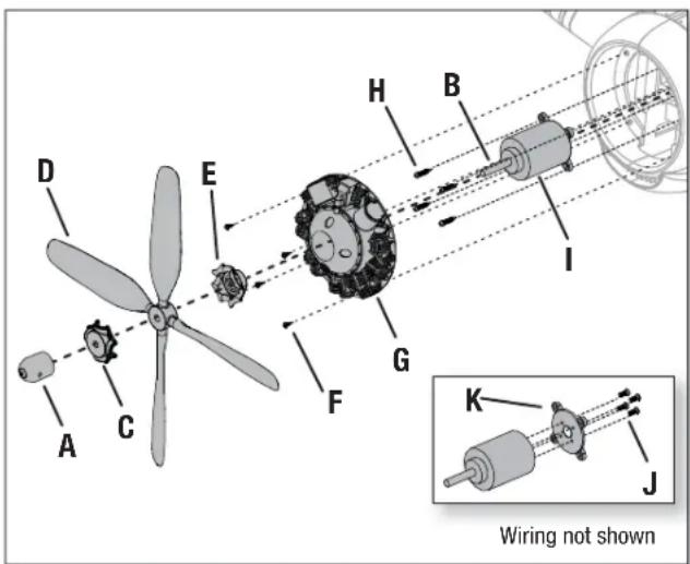
text_image
D E H B I G F C A K J Wiring not shownTroubleshooting Guide AS3X
| Problem Possible Cause Solution | ||
| Oscillation | Damaged propeller or spinner | Replace propeller or spinner |
| Imbalanced propeller | Balance the propeller. For more information, view John Redman's propeller balancing video at www.horizonhobby.com | |
| Motor vibration Replace parts or correctly align all parts and tighten fasteners as needed | ||
| Loose receiver Align and secure receiver in fuselage | ||
| Loose aircraft controls Tighten or otherwise secure parts (servo, arm, linkage, horn and control surface) | ||
| Worn parts Replace worn parts (especially propeller, spinner or servo) | ||
| Irregular servo movement Replace servo | ||
| Inconsistent flight performance | Trim is not at neutral If you adjust trim more than 8 clicks, adjust the clevis to remove trim | |
| Sub-Trim is not at neutral No Sub-Trim is allowed. Adjust the servo linkage | ||
| Aircraft was not kept im-mobile for 5 seconds after battery connection | With the throttle stick in lowest position. Disconnect battery, then reconnect battery and keep the aircraft still for 5 seconds | |
| Incorrect response to the AS3X Control Direction Test | Incorrect direction settings in the receiver, which can cause a crash | DO NOT fly. Correct the direction settings (refer to the receiver manual), then fly |
Troubleshooting Guide
| Problem Possible Cause Solution | ||
| Aircraft will not respond to throttle but responds to other controls | Throttle not at idle and/or throttle trim too high | Reset controls with throttle stick and throttle trim at lowest setting |
| Throttle servo travel is lower than 100% Make sure throttle servo travel is 100% or greater | ||
| Throttle channel is reversed Reverse throttle channel on transmitter | ||
| Motor disconnected from ESC Make sure motor is connected to the ESC | ||
| Extra propeller noise or extra vibration | Damaged propeller and spinner, collet or motor Replace damaged parts | |
| Propeller is out of balance Balance or replace propeller | ||
| Prop nut is too loose Tighten the prop nut | ||
| Reduced flight time or aircraft under-powered | Flight battery charge is low Completely recharge flight battery | |
| Propeller installed backwards Install propeller with numbers facing forward | ||
| Flight battery damaged Replace flight battery and follow flight battery instructions | ||
| Flight conditions may be too cold Make sure battery is warm before use | ||
| Battery capacity too low for flight conditions | Replace battery or use a larger capacity battery | |
| Aircraft will not Bind (during binding) to transmitter | Transmitter too near aircraft during binding process | Move powered transmitter a few feet from aircraft, disconnect and reconnect flight battery to aircraft |
| Aircraft or transmitter is too close to large metal object, wireless source or another transmitter | Move aircraft and transmitter to another location and attempt binding again | |
| The bind plug is not installed correctly in the bind port | Install bind plug in bind port and bind the aircraft to the transmitter | |
| Flight battery/transmitter battery charge is too low | Replace/recharge batteries | |
| Bind switch or button not held long enough during bind process | Power off transmitter and repeat bind process. Hold transmitter bind button or switch until receiver is bound | |
| Aircraft will not connect (after binding) to transmitter | Transmitter too near aircraft during connecting process | Move powered transmitter a few feet from aircraft, disconnect and reconnect flight battery to aircraft |
| Aircraft or transmitter is too close to large metal object, wireless source or another transmitter | Move aircraft and transmitter to another location and attempt connecting again | |
| Bind plug left installed in bind port | Rebind transmitter to the aircraft and remove the bind plug before cycling power | |
| Aircraft bound to different model memory (ModelMatchTM radios only) | Select correct model memory on transmitter | |
| Flight battery/Transmitter battery charge is too low | Replace/recharge batteries | |
| Transmitter may have been bound to a different air-craft using different DSM protocol | Bind aircraft to transmitter | |
| Control surface does not move | Control surface, control horn, linkage or servo damage | Replace or repair damaged parts and adjust controls |
| Wire damaged or connections loose | Do a check of wires and connections, connect or replace as needed | |
| Transmitter is not bound correctly or the incorrect airplanes was selected | Re-bind or select correct airplanes in transmitter | |
| Flight battery charge is low Fully recharge flight battery | ||
| BEC (Battery Elimination Circuit) of the ESC is damaged | Replace ESC | |
| Controls reversed | Transmitter settings are reversed | Perform the Control Direction Test and adjust the controls on transmitter appropriately |
| Motor power pulses then motor loses power | ESC uses default soft Low Voltage Cutoff (LVC) | Recharge flight battery or replace battery that is no longer performing |
| Weather conditions might be too cold | Postpone flight until weather is warmer | |
| Battery is old, worn out, or damaged | Replace battery | |
| Battery C rating might be too small | Use recommended battery | |
AMA National Model Aircraft Safety Code
Effective January 1, 2014
A. GENERAL
A model aircraft is a non-human-carrying aircraft capable of sustained fl ight in the atmosphere. It may not exceed limitations of this code and is intended exclusively for sport, recreation, education and/or competition. All model fl ights must be conducted in accordance with this safety code and any additional rules specifi c to the fl ying site.
- Model aircraft will not be flown:
(a) In a careless or reckless manner.
(b) At a location where model aircraft activities are prohibited.
- Model aircraft pilots will:
(a) Yield the right of way to all man carrying aircraft.
(b) See and avoid all aircraft and a spotter must be used when appropriate. (AMA Document #540-D.)
(c) Not fly higher than approximately 400 feet above ground level within three (3) miles of an airport, without notifying the airport operator.
(d) Not interfere with operations and traffic patterns at any airport, heliport or seaplane base except where there is a mixed use agreement.
(e) Not exceed a takeoff weight, including fuel, of 55 pounds unless in compliance with the AMA Large Model Aircraft program. (AMA Document 520-A.)
(f) Ensure the aircraft is identified with the name and address or AMA number of the owner on the inside or affixed to the outside of the model aircraft. (This does not apply to model aircraft flown indoors).
(g) Not operate aircraft with metal-blade propellers or with gaseous boosts except for helicopters operated under the provisions of AMA Document #555.
(h) Not operate model aircraft while under the influence of alcohol or while using any drug which could adversely affect the pilot's ability to safely control the model.
(i) Not operate model aircraft carrying pyrotechnic devices which explode or burn, or any device which propels a projectile or drops any object that creates a hazard to persons or property. Exceptions:
- Free Flight fuses or devices that burn producing smoke and are securely attached to the model aircraft during flight.
- Rocket motors (using solid propellant) up to a G-series size may be used provided they remain attached to the model during flight. Model rockets may be flown in accordance with the National Model Rocketry Safety Code but may not be launched from model aircraft.
- Offi cially designated AMA Air Show Teams (AST) are authorized to use devices and practices as defined within the Team AMA Program Document (AMA Document #718).
(j) Not operate a turbine-powered aircraft, unless in compliance with the AMA turbine regulations. (AMA Document #510-A).
- Model aircraft will not be flown in AMA sanctioned events, air shows or model demonstrations unless:
(a) The aircraft, control system and pilot skills have successfully demonstrated all maneuvers intended or anticipated prior to the specific event.
(b) An inexperienced pilot is assisted by an experienced pilot.
- When and where required by rule, helmets must be properly worn and fastened. They must be OSHA, DOT, ANSI, SNELL or NOCSAE approved or comply with comparable standards.
B. RADIO CONTROL
- All pilots shall avoid flying directly over unprotected people, vessels, vehicles or structures and shall avoid endangerment of life and property of others.
- A successful radio equipment ground-range check in accordance with manufacturer's recommendations will be completed before the first flight of a new or repaired model aircraft.
- At all fl ying sites a safety line(s) must be established in front of which all fl ying takes place (AMA Document #706.)
(a) Only personnel associated with flying the model aircraft are allowed at or in front of the safety line.
(b) At air shows or demonstrations, a straight safety line must be established.
(c) An area away from the safety line must be maintained for spectators.
(d) Intentional fl ying behind the safety line is prohibited.
- RC model aircraft must use the radio-control frequencies currently allowed by the Federal Communications Commission (FCC). Only individuals properly licensed by the FCC are authorized to operate equipment on Amateur Band frequencies.
- RC model aircraft will not operate within three (3) miles of any pre-existing fl ying site without a frequency-management agreement (AMA Documents #922 and #923.)
- With the exception of events fl own under offi cial AMA Competition Regulations, excluding takeoff and landing, no powered model may be fl own outdoors closer than 25 feet to any individual, except for the pilot and the pilot's helper(s) located at the fl ight line.
- Under no circumstances may a pilot or other person touch a model aircraft in flight while it is still under power, except to divert it from striking an individual.
- RC night fl ying requires a lighting system providing the pilot with a clear view of the model's attitude and orientation at all times. Hand-held illumination systems are inadequate for night fl ying operations.
- The pilot of a RC model aircraft shall:
(a) Maintain control during the entire flight, maintaining visual contact without enhancement other than by corrective lenses prescribed for the pilot.
(b) Fly using the assistance of a camera or First-Person View (FPV) only in accordance with the procedures outlined in AMA Document #550.
(C) Fly using the assistance of autopilot or stabilization system only in accordance with the procedures outlined in AMA Document #560.
Please see your local or regional modeling association's guidelines for proper, safe operation of your model aircraft.
Limited Warranty
What this Warranty Covers
Horizon Hobby, LLC, (Horizon) warrants to the original purchaser that the product purchased (the "Product") will be free from defects in materials and workmanship at the date of purchase.
What is Not Covered
This warranty is not transferable and does not cover (i) cosmetic damage, (ii) damage due to acts of God, accident, misuse, abuse, negligence, commercial use, or due to improper use, installation, operation or maintenance, (iii) modification of or to any part of the Product, (iv) attempted service by anyone other than a Horizon Hobby authorized service center, (v) Product not purchased from an authorized Horizon dealer, or (vi) Product not compliant with applicable technical regulations, or (vii) use that violates any applicable laws, rules, or regulations.
OTHER THAN THE EXPRESS WARRANTY ABOVE, HORIZON MAKES NO OTHER WARRANTY OR REPRESENTATION, AND HEREBY DISCLAIMS ANY AND ALL IMPLIED WARRANTIES, INCLUDING, WITHOUT LIMITATION, THE IMPLIED WARRANTIES OF NON-INFRINGEMENT, MERCHANTABILITY AND FITNESS FOR A PARTICULAR PURPOSE. THE PURCHASER ACKNOWLEDGES THAT THEY ALONE HAVE DETERMINED THAT THE PRODUCT WILL SUITABLY MEET THE REQUIREMENTS OF THE PURCHASER'S INTENDED USE.
Purchaser's Remedy
Horizon's sole obligation and purchaser's sole and exclusive remedy shall be that Horizon will, at its option, either (i) service, or (ii) replace, any Product determined by Horizon to be defective. Horizon reserves the right to inspect any and all Product(s) involved in a warranty claim. Service or replacement decisions are at the sole discretion of Horizon. Proof of purchase is required for all warranty claims. SERVICE OR REPLACEMENT AS PROVIDED UNDER THIS WARRANTY IS THE PURCHASER'S SOLE AND EXCLUSIVE REMEDY.
Limitation of Liability
HORIZON SHALL NOT BE LIABLE FOR SPECIAL, INDIRECT, INCIDENTAL OR CONSEQUENTIAL DAMAGES, LOSS OF PROFITS OR PRODUCTION OR COMMERCIAL LOSS IN ANY WAY, REGARDLESS OF WHETHER SUCH CLAIM IS BASED IN CONTRACT, WARRANTY, TORT, NEGLIGENCE, STRICT LIABILITY OR ANY OTHER THEORY OF LIABILITY, EVEN IF HORIZON HAS BEEN ADVISED OF THE POSSIBILITY OF SUCH DAMAGES. Further, in no event shall the liability of Horizon exceed the individual price of the Product on which liability is asserted. As Horizon has no control over use, setup, fi nal assembly, modification or misuse, no liability shall be assumed nor accepted for any resulting damage or injury. By the act of use, setup or assembly, the user accepts all resulting liability. If you as the purchaser or user are not prepared to accept the liability associated with the use of the Product, purchaser is advised to return the Product immediately in new and unused condition to the place of purchase.
Law
These terms are governed by Illinois law (without regard to conflict of law principals). This warranty gives you specific legal rights, and you may also have other rights which vary from state to state. Horizon reserves the right to change or modify this warranty at any time without notice.
WARRANTY SERVICES
Questions, Assistance, and Services
Your local hobby store and/or place of purchase cannot provide warranty support or service. Once assembly, setup or use of the Product has been started, you must contact your local distributor or Horizon directly. This will enable Horizon to better answer your questions and service you in the event that you may need any assistance. For questions or assistance, please visit our website at www.horizonhobby.com, submit a Product Support Inquiry, or call the toll free telephone number referenced in the Warranty and Service Contact Information section to speak with a Product Support representative.
Inspection or Services
If this Product needs to be inspected or serviced and is compliant in the country you live and use the Product in, please use the Horizon Online Service Request submission process found on our website or call Horizon to obtain a Return Merchandise Authorization (RMA) number. Pack the Product securely using a shipping carton. Please note that original boxes may be included, but are not designed to withstand the rigors of shipping without additional
protection. Ship via a carrier that provides tracking and insurance for lost or damaged parcels, as Horizon is not responsible for merchandise until it arrives and is accepted at our facility. An Online Service Request is available at http://www.horizonhobby.com/content/_service-center_render-service-center. If you do not have internet access, please contact Horizon Product Support to obtain a RMA number along with instructions for submitting your product for service. When calling Horizon, you will be asked to provide your complete name, street address, email address and phone number where you can be reached during business hours. When sending product into Horizon, please include your RMA number, a list of the included items, and a brief summary of the problem. A copy of your original sales receipt must be included for warranty consideration. Be sure your name, address, and RMA number are clearly written on the outside of the shipping carton.
NOTICE: Do not ship LiPo batteries to Horizon. If you have any issue with a LiPo battery, please contact the appropriate Horizon Product Support offi ce.
Warranty Requirements
For Warranty consideration, you must include your original sales receipt verifying the proof-of-purchase date. Provided warranty conditions have been met, your Product will be serviced or replaced free of charge. Service or replacement decisions are at the sole discretion of Horizon.
Non-Warranty Service
Should your service not be covered by warranty, service will be completed and payment will be required without notifi cation or estimate of the expense unless the expense exceeds 50% of the retail purchase cost. By submitting the item for service you are agreeing to payment of the service without notifi cation. Service estimates are available upon request. You must include this request with your item submitted for service. Non-warranty service estimates will be billed a minimum of 12 hour of labor. In addition you will be billed for return freight. Horizon accepts money orders and cashier's checks, as well as Visa, MasterCard, American Express, and Discover cards. By submitting any item to Horizon for service, you are agreeing to Horizon's Terms and Conditions found on our website http://www.horizonhobby.com/content/_service-center_render-service-center.
ATTENTION: Horizon service is limited to Product compliant in the country of use and ownership. If received, a non-compliant Product will not be serviced. Further, the sender will be responsible for arranging return shipment of the un-serviced Product, through a carrier of the sender's choice and at the sender's expense. Horizon will hold non-compliant Product for a period of 60 days from notification, after which it will be discarded.
10/15/15
Contact Information
| Country of Purchase Horizon Hobby Phone Number/Email Address Address | |||
| United States of America | Horizon Service Center (Repairs and Repair Requests) | servicecenter.horizonhobby.com/RequestForm/ | 4105 Fieldstone RdChampaign, Illinois, 61822 USA |
| Horizon Product Support (Product Technical Assistance) | productsupport@horizonhobby.com888-959-2305 | ||
| Sales | sales@horizonhobby.com888-959-2305 | ||
| United Kingdom | Service/Parts/Sales: Horizon Hobby Limited | sales@horizonhobby.co.uk+44 (0) 1279 641 097 | Units 1–4 , Ployters Rd, Staple TyeHarlow, Essex, CM18 7NS, United Kingdom |
| Germany | Horizon Technischer Service service@horizonhobby.deSales: Horizon Hobby GmbH +49 (0) 4121 2655 100 | Christian-Junge-Straße 125337 Elmshorn, Germany | |
| France | Service/Parts/Sales: Horizon Hobby SAS | infofrance@horizonhobby.com 11 Rue Georges Charpak+33 (0) 1 60 18 34 90 | 77127 Lieusaint, France |
| China | Service/Parts/Sales: Horizon Hobby – China | info@horizonhobby.com.cn Room 506, No. 97 Changshou Rd.+86 (021) 5180 9868 | Shanghai, China 200060 |
FCC Information
Operation is subject to the following two conditions: (1) This device may not cause harmful interference, and (2) this device must accept any interference received, including interference that may cause undesired operation.

CAUTION: Changes or modifications not expressly approved by the party responsible for compliance could void the user's authority to operate the equipment.
This product contains a radio transmitter with wireless technology which has been tested and found to be compliant with the applicable regulations governing a radio transmitter in the 2.400GHz to 2.4835GHz frequency range.
IC Information
This device complies with Industry Canada licence-exempt RSS standard(s). Operation is subject to the following two conditions: (1) this device may not
cause interference, and (2) this device must accept any interference, including interference that may cause undesired operation of the device.
Compliance Information for the European Union
CE
EFL F4U-4 1.2M BNF Basic (EFL8550)
EU Compliance Statement: Horizon Hobby, LLC hereby declares that this product is in compliance with the essential requirements and other relevant provisions of the R&TTE and EMC Directive.
A copy of the EU Declaration of Conformity is available online at: http://www.horizonhobby.com/content/support-render-compliance.
Instructions for disposal of WEEE by users in the European Union

This product must not be disposed of with other waste. Instead, it is the user's responsibility to dispose of their waste equipment by handing it over to a designated collections point for the recycling of waste electrical and electronic equipment. The separate collection and recycling of your waste equipment at the time of disposal will help to conserve natural resources and ensure that it is recycled in a manner that protects human health and the environment. For more information about where you can drop off your waste equipment for recycling, please contact your local city offi ce, your household waste disposal service or where you purchased the product.

Replacement Parts • Ersatzteile • Pièces de rechange • Pezzi di ricambio
| Part # | Nummer Numéro | Codice | Description | Beschreibung | Description | Descrizione |
| EFLG1590R | 90 DEG RETRACTS PR: F4U-4 1.2M | E-fl ite 90° rotierendes Fahrwerksset: F4U-4 1,2 m | F4U-4 1.2M - Mécanisme pour train rentrant électrique rotatif 90° | Carrello retrattile 90° paio: F4U-4 1,2 m |
| EFL8501 | FUSELAGE W/HATCH: F4U-4 1.2M | E-fl ite Rumpf m. Abdeckung: F4U-4 1,2 m | F4U-4 1.2M - Fuselage avec trappe | Fusoliera con sportello capottina: F4U-4 1,2 m |
| EFL8502 | PAINTED WING: F4U-4 1.2M | E-flite Tragfläche, lackiert: F4U-4 1,2 m | F4U-4 1.2M - Aile peinte | Ala verniciata: F4U-4 1,2 m |
| EFL8503 | HORIZONTAL STAB: F4U-4 1.2M | E-flite Höhenruder: F4U-4 1,2 m | F4U-4 1.2M - Stabilisateur | Stabilizzatore orizzontale: F4U-4 1,2 m |
| EFL8504 | HATCH W/PILOT: F4U-4 1.2M | E-fl ite Kabinenhaube m. Pilot: F4U-4 1,2 m | F4U-4 1.2M - Cockpit avec pilote | Sportello capottina con pilotino: F4U-4 1,2 m |
| EFL8505 | PUSHROD SET: F4U-4 1.2M | E-flite Gestängeset: F4U-4 1,2 m | F4U-4 1.2M - Set de tringleries | Set aste di comando: F4U-4 1,2 m |
| EFL8506 | DECAL SHEET: F4U-4 1.2M | E-flite Dekorbogen: F4U-4 1,2 m | F4U-4 1.2M - Planche de décoration | Set decalcomanie: F4U-4 1,2 m |
| EFL8507 | PROP ADAPTER W/HUB: F4U-4 1.2M | E-fl ite Luftschraubenmitnehmer: F4U-4 1,2 m | F4U-4 1.2M - Adaptateur d'hélice avec écrou | Adattatore elica con mozzo: F4U-4 1,2 m |
| EFL8508 | HARDWARE SET: F4U-4 1.2M | E-flite Hardwareset: F4U-4 1,2 m | F4U-4 1.2M - Visserie | Set hardware: F4U-4 1,2 m |
| EFL8509 | DROP TANK: F4U-4 1.2M | E-flite Abwurftank: F4U-4 1,2 m | F4U-4 1.2M - Réservoir largable | Serbatoio ausiliare: F4U-4 1,2 m |
| EFL8510 | SERVO TAPE: F4U-4 1.2M | E-flite Servotape: F4U-4 1,2 m | F4U-4 1.2M - Adhésif pour servo | Nastro servocomando: F4U-4 1,2 m |
| EFL8511 | LANDING GEAR PARTS: F4U-4 1.2M | E-flite Fahrwerksteile: F4U-4 1,2 m | F4U-4 1.2M - Pièces pour train d'atterrissage | Componenti carrello d'atterraggio: F4U-4 1,2 m |
| EFL8512 | WHEEL SET: F4U-4 1.2M | E-flite Räderset: F4U-4 1,2 m | F4U-4 1.2M - Roues | Set ruote: F4U-4 1,2 m |
| EFLA1140W 40 AMP | Brushless ESC | 40 AMP bürstenloser Geschwindigkeitsregler | Contrôleur Brushless 40A | 40 A brushless ESC |
| EFLM4115 | BL15 Brushless Outrunner 850kV | BL15 Brushless Outrunner 850kV | Moteur brushless BL15 850Kv à cage tournante | BL15 Brushless Outrunner 850kV |
| EFLP105084BL | Propeller 4 Blade 10.5 x 8: P-51D 1.2m | 4-Blatt Propeller 10,5 x 8: P-51D 1,2m | P-51D 1.2m - Hélice quadripale 10,5 x 8 | Elica quadripala 10.5 x 8: P-51D 1.2m |
| SPMSA330 | 9 Gram Servo | 9 Gramm Servo | Servo 9g | Servocomando 9g |
Optional Parts • Optionale Bauteile • Pièces optionnelles • Pezzi opzionali
| Part # | Nummer Numéro | Codice | Description Beschreibung Description Descrizione | |||
| EFLA250 | Park Flyer Tool Assortment, 5 pc | Park Flyer Werkzeugsortiment, 5 teilig | Assortiment d'outils park flyer, 5pc | Park Flyer assortimento attrezzi, 5 pc |
| EFLAEC302 | EC3 Battery Connector, Female (2) | EC3 Akkukabel, Buchse (2) Prise EC3 femelle (2pc) | EC3 Connettore femmina x batteria (2) | |
| EFLAEC303 EC3 Device/Battery Connector, Male/Female | EC3 Kabelsatz, Stecker/Buchse Prise EC3 male/femelle | EC3 Connettore batteria maschio/femmina | ||
| EFLB22003S50 | 11.1V 3S 50C 2200MAH Li-Po 11.1V 3S 50C 2200MAH Li-Po 11.1V 3S 50C 2200MAH Li-Po | Po | ||
| DYNC2020A | Prophet Sport Duo 50W x 2 AC Battery Charger | Dynamite Prophet Sport Duo 50W x 2 AC Ladegerät, EU | Chargeur Prophet Sport Duo 50W x 2 AC | Caricabatterie Prophet Sport Duo 50W x 2 AC |
| DYNC2010CA | Prophet Sport Plus 50W AC DC Charger | Dynamite Ladegerät Prophet Sport Plus 50W AC/DC EU | Chargeur Prophet Sport Plus 50W AC DC | Caricabatterie Prophet Sport Plus 50W AC DC |
| SPMA3801 | AS3X Programming Cable - Audio Interface | Spektrum Audio-Interface AS3X Emp-fänger Programmierkabel | Câble de programmation audio AS3X pour smartphone | Cavo di programmazione AS3X - Interfaccia audio |
| SPMA3065 | AS3X Programming Cable - USB Interface | Spektrum USB-Interface AS3X Emp-fänger Programmierkabel | Câble de programmation USB AS3X pour PC | Cavo di programmazione AS3X - Interfaccia USB |
| EFLA111 | Li-Po Cell Voltage Checker | Li-Po Cell Voltage Checker | Testeur de tension d'éléments Li-Po | Voltmetro verifica batterie LiPo |
| DYN1405 | Li-Po Charge Protection Bag, Large | Dynamite LiPoCharge Protection Bag groß | Sac de charge Li-Po, grand modèle. | Sacchetto grande di protezione per carica LiPo |
| DYN1400 | Li-Po Charge Protection Bag, Small | Dynamite LiPoCharge Protection Bag klein | Sac de charge Li-Po, petit modèle | Sacchetto piccolo di protezione per carica LiPo |
| DX6i DSMX 6-Channel Transmitter | Spektrum DX6i DSMX 6-Kanal Sender | Emetteur DX6i DSMX 6 voies | DX6i DSMX Trasmettitore 6 canali | |
| DX6 DSMX 6-Channel Transmitter | Spektrum DX6 DSMX 6-Kanal Sender | Emetteur DX6 DSMX 6 voies | DX6 DSMX Trasmettitore 6 canali | |
| DX7 DSMX 7-Channel Transmitter | Spektrum DX7 DSMX 7 Kanal Sender | Emetteur DX7 DSMX 7 voies | DX7 DSMX Trasmettitore 7 canali | |
| DX9 DSMX 9-Channel Transmitter | Spektrum DX9 DSMX 9 Kanal Sender | Emetteur DX9 DSMX 9 voies | DX9 DSMX Trasmettitore 9 canali | |
| DX18 DSMX 18-Channel Transmitter | Spektrum DX18 DSMX 18 Kanal Sender | Emetteur DX18 DSMX 18 voies | DX18 DSMX Trasmettitore 18 canali | |
© 2016 Horizon Hobby, LLC.
E-fl ite, AS3X, DSM, DSM2, DSMX, the DSMX logo, Bind-N-Fly, Z-Foam, ModelMatch, Dynamite, EC3, Prophet and the Horizon Hobby logo are trademarks or registered trademarks of Horizon Hobby, LLC.
The Spektrum trademark is used with permission of Bachmann Industries, Inc.
Futaba is a registered trademark of Futaba Denshi Kogyo Kabushiki Kaisha Corporation of Japan.
All other trademarks, service marks and logos are property of their respective owners.
US 8,672,726. Other patents pending.
http://www.e-fl iterc.com/