V-CD510 - Car stereo VARTA - Free user manual and instructions
Find the device manual for free V-CD510 VARTA in PDF.

User questions about V-CD510 VARTA
0 question about this device. Answer the ones you know or ask your own.
Ask a new question about this device
Download the instructions for your Car stereo in PDF format for free! Find your manual V-CD510 - VARTA and take your electronic device back in hand. On this page are published all the documents necessary for the use of your device. V-CD510 by VARTA.
USER MANUAL V-CD510 VARTA
Thank you for purchasing our product. For safety, it is strongly recommended to read this manual carefully before connecting, operating and/or adjusting the product and keep the manual for reference in the future.
Table of contents 2
Before you start 3
Utilization of the product 3
Important safeguards 3
Installation/Connection 4
Installation 4
General notes 4
Din Front/Rear-Mount 4
- DIN front-mount (Method A) 4
Dismantling the unit 4
Trim frame installation 5
- DIN rear-mount (Method B) 5
Detachable control panel 5
Anti-theft system 5
Connection 6
Connection diagram 6
ISO Connection table 6
Operation 7
Control elements 7
Front panel 7
Inner panel 7
Remote controller 8
Changing the battery 8
Use of Remote controller 8
LCD layout 9
General operations 10
Reset the unit 10
Power on/off 10
Volume control 10
Setting the sound parameters 10
Setting other features 10
Sound mute 10
Mode select 10
Display 10
AUX in jack 10
Radio operations 11
Band select 11
Auto/Manual tuning 11
Programming tuner stations 11
Automatic store/preset scan 11
Mono/Stereo control 11
Local/distant reception mode 11
RDS function 11
AF (Alternative Frequencies) function 11
TA (Traffic Alarm) function 11
PTY (Program Type) 12
REG control 12
Other parameter setting 12
Disc/USB/SD operations 12
USB/SD notes 12
Inserting an SD card/USB device 12
Insert/Eject disc 12
Play/pause 13
Fast forward/rewind 13
Scanning tracks 13
Repeat 13
Random playback 13
Previous/next track 13
MP3 track search 13
General information 14
Handling compact discs 14
Cleaning discs 14
Cleaning the unit body 14
Accessories 14
Troubleshooting guide 15
Specification 16
UTILIZATION OF THE PRODUCT
If you want to dispose this product, do not mix it with general household waste. There is a separate collection system for used electronic products in accordance with legislation that requires proper treatment, recovery and recycling.
Please contact your local authorities for the correct method of disposal. By doing so, you will ensure that your disposed product undergoes the necessary treatment, recovery and recycling and thus prevent potential negative effects on the environment and human health.
IMPORTANT SAFEGUARDS
- Using the device at temperature below -10°C may cause the breakage of the device. Before using please heat up the passenger compartment to the recommended temperature!
- Read carefully through this manual to familiarize yourself with this high-quality system.
- Disconnect the vehicle's negative battery terminal while mounting and connecting the unit.
- When replacing the fuse, be sure to use one with an identical amperage rating. Using a fuse with a higher amperage rating may cause serious damage to the unit.
- Do not attempt to disassemble the unit. Laser beams from the optical pickup are dangerous to the eyes.
• Make sure that pins or other foreign objects do not get inside the unit; they may cause malfunctions, or create safety hazards such as electrical shock or laser beam exposure. - If you have parked the car for a long time in hot or cold weather, wait until the temperature in the car becomes normal before operating the unit.
- Do not open covers and do not repair yourself. Consult the dealer or an experienced technician for help.
- Make sure you disconnect the power supply and aerial if you will not be using the system for a long period or during a thunderstorm.
• Make sure you disconnect the power supply if the system appears to be working incorrectly, is making an unusual sound, has a strange smell, has smoke emitting from it or liquids have got inside it. Have a qualified technician check the system.
- The unit is designed for negative terminal of the battery, which is connected to the vehicle metal. Please confirm it before installation.
Do not allow the speaker wires to be shorted together when the unit is switched on. Otherwise it may overload or burn out the power amplifier.
- Do not install the detachable panel before connecting the wire.

Installation/Connection
INSTALLATION
General notes
- Choose the mounting location where the unit will not interfere with the normal driving function of the driver.
- Before finally installing the unit, connect the wiring and make sure that the unit works properly.
- Consult with your nearest dealer if installation requires the drilling of holes or other modifications of the vehicle.
- Install the unit where it does not get in the driver's way and cannot injure the passenger if there is a sudden stop, like an emergency stop.
- If installation angle exceeds 30^ from horizontal, the unit may not perform properly.
- Avoid installing the unit where it would be subject to high temperature, such as from direct sunlight, or from hot air, from the heater, or where it would be subject to dust, dirt or excessive vibration.
Din Front/Rear-Mount
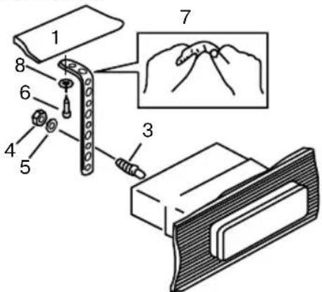
This unit can be properly installed either from 'Front' (conventional DIN Front-mount) or 'Rear' (DIN Rear-mount installation, utilizing threaded screw Holes at the sides of the unit chassis). For details, refer to the following illustrated installation methods.
1. DIN front-mount (Method A)

text_image
1 182 53 2 3-
Car dashboard
-
Sleeve
-
Screw
-
Nut (5 mm)
- Spring washer
- Screw (5 x 25 mm)
- Metal strap
- Flat washer
text_image
Technical diagram showing labeled parts of a mechanical assembly with numbered annotations- Install the sleeve into the dashboard; ensure it is installed with the correct side and there are no obstacles (wires, dashboard elements, etc) for the unit installation.
- After installing the sleeve into the dashboard, bend tabs fitting to the size of the dashboard to fix the sleeve in place.
- Use the metal strap to fix the rear side of the unit. Determine a place for fixing and install the strap as shown in the picture. You can bend the strap to the needed angle with your hands.
- Make the necessary wire connections. Ensure the connections are correct.
- Install the unit into the sleeve until the side locks are fixed.
Dismantling the unit

text_image
Diagram illustrating a three-step electrical circuit: panel assembly, key insertion, and switch operation.a - Trim frame
b - Frame uninstall direction
c - Release key insertion
- Switch off the unit and detach the front panel.
- Insert your fingers into the groove in the front side of the trim frame (apply some effort to detach the frame). Pull the frame to detach it.
- Insert the supplied release keys into the both sides of the unit body to click, as shown in the picture. To extract the unit from the dashboard, pull the release keys or the unit body to pull it out. Before detaching the unit, ensure it is not fixed with the metal strap.
Trim frame installation
To install the trim frame, press it to the unit body and push it to fix it in place. This should be done before installing the front panel; otherwise you are not able to install the trim frame. When the trim frame being installed the side with the groove should face down and fixed first.
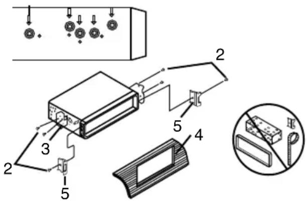
2. DIN rear-mount (Method B)
For this method, use the screw holes in the lateral sides of the unit. Fix the unit with the help of the factory radio mounting brackets.
text_image
Technical diagram of a device with numbered components and exploded view, including labeled parts 2 through 5.- Select a position in which the screw holes of the brackets (3) are aligned with the screw holes in the unit body, and screw in two screws (2) in each side.
-
Screw.
-
Factory radio mounting brackets.
- Vehicle dashboard.
- Lock (remove this part).
The outer trim frame and mounting sleeve are not used for method of installation.
Detachable control panel
Insert the left locker of the body into the fixing hole on the left side of the panel, then insert the right locker into the right hole of the panel. Press on the upper part of the panel until a click.
To detach the front panel, press OPEN button. Push the panel to the right to detach the left locker. Then detach the right locker.
The control panel can easily be damaged by shocks. After removing it, place it in a protective case and be careful not to drop it or subject it to strong shocks. The rear connector that connects the main unit and the control panel is an extremely important part. Be careful not to damage it by pressing on it with fingernails, pens, screwdrivers, etc.
7 If the control panel is dirty, wipe off the dirt with soft, dry cloth only. And use a cotton swab soaked in isopropyl alcohol to clean the socket on the back of the control panel.
Anti-theft system
The front panel of this unit can be stored in the included protective case when not in used and carried away when you leave the vehicle to deter theft.
Switch off the power of the unit. Detach the front panel, then put it to the protective case and take it with you.

Installation/Connection
CONNECTION
Connection diagram

text_image
Fuse Line-out left (White) Line-out right (Red) ISO connector Antenna jack B 1 3 5 7 2 4 6 8 1 3 5 7 2 4 6 8 A Connector A 1. - 2. - 3. - 4. Memory +12V 5. Auto antenna output 6. - 7. +12V (to ignition key) 8. GroundConnector B
- Rear right speaker (+)
- Rear right speaker (-)
- Front right speaker (+)
- Front right speaker (-)
- Front left speaker (+)
- Front left speaker (-)
- Rear left speaker (+)
- Rear left speaker (-)
ISO connection table
| Location Function | ||
| Connector A Connector B | ||
| 1 - Rear right (+) - Blue | ||
| 2 - Rear right (-) - Blue/White | ||
| 3 - Front right (+) - Grey | ||
| 4 Battery +12V/Yellow Front right (-) - Grey/White | ||
| 5 Power antenna/Orange Front left (+) - Green | ||
| 6 - Front left (-) - Green/White | ||
| 7 Ignition/Red Rear left (+) - Brown | ||
| 8 Ground/Black Rear left (-) - Brown/White | ||
Power antenna wire is intended for power supply of the antenna and for remote control of an additional amplifier.
CONTROL ELEMENTS
Front panel
- MODE button
- PWR button
- VOL knob
- DIS button
- IR sensor
- Display
- AF button
- PTY button
- TA button
- ▶ button
-
OPEN button
-
USB port
- MUTE button
- AS/PS button
- 1/PAUSE button
- 2/RPT button
- 3/INT button
- 4/RDM button
- 5/-10 button
- 6/+10 button
- BAND button
- AUX in jack
- ◀ button

text_image
1 2 3 4 65 7 8 9 10 11 12 PWR V-CD510 VARTA 4 x 50W OPEN TA PTY AT A/PS PULSE RPT INT RCH IO +IO BAND AUE IN 13 14 15 16 17 18 19 20 21 22 23Inner panel
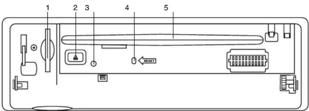
text_image
1 2 3 4 5 RESET- SD/MMC memory card slot
- EJECT button
- Panel status indicator
- RESET button (hole)
- Disc slot
Pressing RESET hole will erase the clock setting and stored stations.
Panel status indicator lights up when you slide the panel down, flashes when you remove the panel.
Remote controller
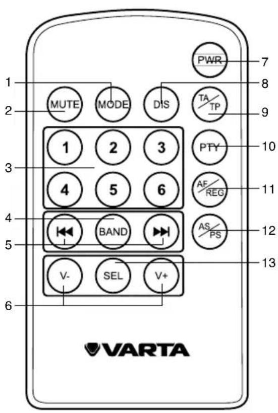
text_image
1 2 3 4 5 6 MUTE MODE DIS TA TP 1 2 3 4 5 6 PWR 7 8 9 PTY 10 AF/ REG 11 AS/ PS 12 13 V- SEL V+ VARTA- MODE button
- MUTE button
- Number buttons
- BAND button
- ◀◀/▶buttons
- V-/V+ buttons
- PWR button
- DIS button
- TA/TP button
- PTY button
- AF/REG button
- AS/PS button
- SEL button
Changing the battery
Press the catch and at the same time pull out the battery tray. Insert the 1 x lithium battery, type CR 2025 3V battery with the stamped (+) mark facing upward. Insert the battery tray into the remote control.
Use of Remote Controller
- Use the remote control within 7 meters from the IR sensor of the unit, and keep it within +/-30° angle.
• Always keep the battery out of the reach of children. Children may swallow it.
• If the remote control will not be in use for a month, it is recommended that you remove the battery. - Do not disassemble or heat the battery.
- Do not dispose of battery into any fire source.
LCD layout
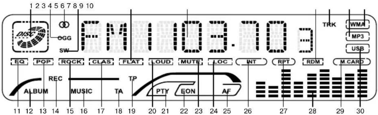
text_image
1 2 3 4 5 6 7 8 9 10 DISC OGG SW FM103.703 EQ POP ROCK CLAS FLAT LOUD MUTE LOC INT RPT RDM WMA MP3 USB REC AUDIO MUSIC TA TP PTY EON AF 11 12 13 14 15 16 17 18 19 20 21 22 23 24 25 26 27 28 29 30- Disc playback indicator
- Not active for this model
- Stereo signal reception indicator
- Not active for this model
- FLAT equalizer mode indicator
- Digit display
- Random playback indicator
- Track display indicator
- MP3 playback indicator
- WMA playback indicator
- Equalizer indicator
- Album display indicator
- POP equalizer mode indicator
- Not active for this model
-
ROCK equalizer mode indicator
-
Music playback indicator
- CLAS equalizer mode indicator
- TA function indicator
- TP function indicator
- Loudness indicator
- PTY function indicator
- EON function indicator
- Sound mute indicator
- Local reception mode indicator
- AF function indicator
- Intro playback indicator
- Repeat playback indicator
- Equalizer graphic indicator
- Memory card indicator
- USB indicator
GENERAL OPERATIONS
Resetting the unit
Operating the unit for the first time or after replacing the car battery, you must reset the unit.
Press OPEN button on the panel to open the panel and press RESET button to restore the unit to its original factory settings.
Power on/off
Press any button (except OPEN) to turn on the unit. Press and hold PWR button to switch the unit off.
After the unit is off, the volume I and radio current settings will be memorized, and when you turn the unit on it will resume the stored status you previously set.
Volume control
Rotate VOL knob on the panel or press V+/V- buttons on the RC to adjust the volume level.
Setting the sound parameters
Press repeatedly VOL knob on the panel or SEL button on the RC to select an aud setting: VOL (volume) => BAS (bass) => TRE (treble) => BAL (balance) => FAD (fader). Rotate VOL knob on the panel or press V+/- buttons on the RC to adjust each setting.
- If the unit is turned off, all the settings of each mode will be saved.
- If cutting off battery power or resetting the unit, all the settings will return to facto default settings.
- When DSP is set to any mode, Balance and Treble are not adjustable.
- If you don't adjust the setting within several seconds after selecting the desired setting, the unit will automatically return to the current mode being displayed.
Setting other features
Press and hold VOL knob on the panel or SEL button on the RC, and then shortly press this knob/button repeatedly to select a setting. Rotate VOL knob on the panel or press V+/-buttons on the RC to adjust each setting.
INVOL: Set default volume level when the unit is turned on.
CLOCK: you can set the clock. Rotate VOL knob clockwise to set minutes; rotate VOL knob counterclockwise to set hours.
24 HOUR: choose 24 hour clock display mode or 12 hour clock display mode.
LOUD ON/OFF: Enable LOUD ON (Default is LOUD OFF).
BEEP ON/OFF: if BEEP on, pressing any key will make a beep sound.
DSP: Choose intended sound effect in the sequence: POP => ROCK => CLASS => FLAT e#> NONE.
Sound mute
Press MUTE button to turn the sound off. Press it again or rotate VOL knob on the panel or press V+/- buttons on the RC to resume sound.
Mode select
Press MODE button repeatedly to select: TUNER => CD => SD => USB => AUX.
CD, SD and USB modes are only available if corresponding media device is in the unit.
Display
Press DIS button repeatedly to see current tuning information and time. Sequence of the menu: Clock => PTY => PS => Radio frequency.
AUX in jack
AUX-in jack is intended for connecting an external audio or video equipment to amplify the sound. If connection is made correctly, the audio signal from the external source will be translated through the acoustics of the head unit. This enables to adjust the volume and quality of the sounding. For example, you can connect an MP3-player to listen to tracks using the car acoustic system.
RADIO OPERATIONS
Band select
Press repeatedly BAND button to select your desired radio band during RADIO mode: FM1, FM2, FM3 (OIRT), AM1 (MW1), AM2 (MW2). In each set of the bands you can store up to 6 preset stations, making total 30 preset memory stations.
Auto/Manual tuning
Auto tuning: Press ▶or ▶button on the panel or on the RC. The radio will seek to the nearest up or down strong and clear frequency station. Repeat this action to seek for other desired stations. While seeking, to stop auto tuning press ▶or ▶button.
Manual tuning: Press and hold ◀◀/▶buttons on the panel or on the RC until MANUAL is displayed. Then press repeatedly ◀◀/▶buttons to change the frequency step by step.
Programming tuner stations
There are 6 numbered preset buttons, under which you can store and recall stations for each band. Select the needed station, then press and hold a number button. The station will be saved in the memory under the corresponding number. To recall a stored station, press the corresponding number button.
Automatic store/preset scan
Automatic store: press and hold AS/PS button on the panel or on the RC. The radio will automatically store the 6 strongest available stations to the 6 preset memories of the 3 FM bands or the 2 AM bands (depending on which one is current). To stop auto store, press this button again.
Preset_scan: Press AS/PS button on the panel or on the RC, the receiver will scan the saved stations in the current band.
Mono/Stereo control
Press and hold SEL button on the RC or VOL knob on the panel; then press it repeatedly until the display shows MONO OFF (MONO ON). Turn VOL knob or press V+/- buttons on the RC to switch between ON (mono reception) or OFF (stereo reception).
Improvement of reception of distant stations can be done by selecting mono mode, which may cut down some reception noise.
Local/Distant reception modes
Press and hold SEL button on the RC or VOL knob on the panel; then press it repeatedly until the display shows LOC OFF (LOC ON). Turn VOL knob or press V+/- buttons on the RC to switch between ON (local station reception) or OFF (distant and local station reception).
RDS function
RDS (Radio Data System) service availability varies with areas. Please understand if RDS service is not available in you area, the following service is not available either.
AF (Alternative Frequencies) function
Press AF button on the panel or AF/REG button on the RC to turn the AF function on nor off.
- When the radio signal strength is poor, enabling the AF function will allow the unit to automatically search another station with the same PI (Program Identification) as the current station but with stronger signal strength, so that you do not have to retune the stations when driving between different transmitter coverage areas. When AF symbol is on, it means RDS information is received; when AF symbol is flashing, it means RDS information is not yet received.
TA (Traffic Alarm) function
Press TA button on the panel or TA/TP button on the RC to turn TA function on or off.
- When TA function is activated, it will search the station with TA information automatically. If there is no TA information, it will search the station with TP information automatically, if there is no TP information either, it will return to

Operation
the previous station after searching.
- When receiving the station with TP information but without TA information, TP icon is on and TA icon keeps blinking; when receiving the station with TP and TA information, both TP and TA icons are on.
- When playing in other mode and TA information is received, it will change to the radio mode automatically. After playing over it will return to the previous mode. Press TA or TA/TP button once to ignore the received TA information, press the button twice to turn off the function.
PTY (Program Type)
This radio will allow you to select the type of program required, and will search for a station broadcasting that type of program.
Press PTY to turn on PTY function. Press and hold this button to open the program type list. Rotate VOL knob on the panel or press V+/- buttons on the RC to select a program type. After selecting the type, press PTY button to start search.
During one loop, if desired PTY is not found, the unit will show NOT FND. Press PTY button again to stop the search and switch the PTY function off.
Press and hold AF button on the panel or AF/REG button on the RC to select REG on or off. Default setting is off for REG.
When REG is enabled (on), the receiver accepts regional variants of the tuned station with REG icon turned on.
When REG is disabled (off), the receiver ignores regional variants.
Other parameter setting
Rotate VOL knob or press V+/- buttons on the RC to switch EON on or off.
This unit is equipped with the latest technology of EON (Enhanced Other Networks) control, so that when you are listening to Radio or CD, if there is any travel announcement from a nearby local station, the radio will already be known the frequency of that radio station. Then it will receive the station, turn up the volume, or interrupt the playback of the music for the duration of the announcement. At the end of the announcement the radio will return to its previous state ready for the next announcement.
DISC/USB/SD OPERATIONS
USB/SD notes
USB format supports 2.0. Capacity: up to 8 GB.
For correct and satisfactory operation, licensed SD memory cards of famous brands should be used with this unit. Avoid using memory cards of unknown brands. Capacity: up to 8 Gb.
Inserting SD card/USB device
Insert an MMC card or a USB device into MMC slot (on the inner panel) or USB socket (behind the rubber cover). Then the playing mode will be changed into SD or USB mode automatically. The first card/USB device track playback will start.
When MMC card and USB device are both inserted into their compartment or socket, the playing mode will be changed into the mode of the later one.
Insert/eject discs
- Open the front panel and insert a disc into the disc slot with label side up. Close the front panel. The disc will be automatically loaded into the unit, even when it is in radio mode. For MP3 discs, the first file in the root folder will be played. If an MP3 file has ID3 Tag information in the supported ID3 format, such information will be displayed on the LCD while playback.
- Open the front panel and press EJECT button to eject the disc from the slot. If the disc is not removed from the slot within several seconds, it will be automatically loaded into the slot again. When the disc is ejected and removed, the unit will automatically switch to radio mode.
Play/pause
To ensure good system performance, wait until the unit finishes reading the disc information before proceeding. Press 1/PAUSE button to pause the disc playback. Press this button again to resume playback.
Fast Forward/rewind
Press and hold ▶ button on the panel or on the RC to fast forward. Press and hold ◀ button on the panel or on the RC to fast reverse. Release the button when the desired location is found.
Scanning tracks
Press 3/INT button to play the first 10 seconds of each track. Press this button again to cancel intro playback playback.
Repeat
Press 2/RPT button to repeat the same track continuously. Press this button again to stop repeating.
Random playback
Press 4/RDM button to play all the tracks in random order. Press the button again to stop random play.
Previous/next track
Press 1/2 buttons on the panel or on the RC to go to the previous or next track. Press 5/-10 and 6/+10 buttons to advance to 10 tracks down or up.
MP3 track search
The search modes only works with MP3
discs, USB and memory cards with MP3 files. Cancel random, repeat and intro features before searching.
- File Number Search
Press AS/PS button once to enter file number search; 000 is displayed meaning the unit is ready to accept file number for search. Rotate VOL knob or press V+/- buttons on the RC to input the third digit (from 1 to 9) of file you want to listen to. Press VOL knob on the panel or SEL button on the RC to go to next digit selection. After completing input, press BAND button to play the selected track.
- File Name Search
Press AS/PS button twice; A** is displayed with the first character blinking. Rotate VOL knob or press V+/- buttons on the RC to input the first alphabet (from A to Z) or digit (from 0 to 9) of file name you want to listen to. Press SEL button on the RC or VOL knob on the panel to go to next digit. After completing input, press BAND button to play.
If there is no file found, the unit will show NO MATCH and return to initial input ready mode automatically.
- Folder Search
Press AS/PS button 3 times, the first folder name will be displayed. Rotate VOL knob or press V+/- buttons on the RC to choose the needed folder. Press BAND button to play the first track in the selected folder.
If the device contains no folders, ROOT will be displayed.

General information
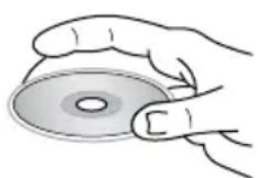
Handling compact discs
- Do not insert anything other than a CD into the CD loading slot.
- Do not use cracked, chipped, warped, or otherwise damaged discs as they may cause skipping or noise damage the player.
- Handle the disc only by the edges (as shown in the picture). To keep discs clean do not touch its surface.
- Store discs in their cases when not in use.
- Do not expose discs to direct sunlight, high humidity, high temperature or dust.
- Prolonged exposure to extreme temperature (such as leaving the discs in your car during summertime) can wrap a disc.
- Do not attach labels, write on or apply chemicals to the surface of the discs.
- Do not touch the recorded surface of the discs.
- Use 12-cm CDs. Use only conventional, fully circular discs. Do not use shaped discs.
Cleaning the unit body
Wipe with a soft cloth. If the cabinet is very dampen (not dropping wet) the cloth with a weak solution of soapy water, and then wipe clean.
Accessories
- Receiver 1 pc
- Front panel 1 pc
- Protective case 1 pc
- ISO cable set 1 pc
- Remote controller 1 pc
- Mounting parts:
Nut 5 mm 1 pc
Spring washer 1 pc
Plain washer 1 pc
Rear bolt 1 pc
Screw 4 pcs
Metal strap 1 pc
Release key 2 pcs
Mounting sleeve 1 pc
Trim frame 1 pc
-
Instruction manual 1 pc
-
Warranty card 1 pc
-
Consumer information 1 pc
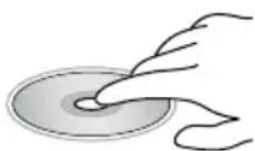
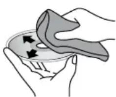
Cleaning discs
Fingerprints should be carefully wi ped from the surface of disc with a soft cloth. Unlike conventional records, compact discs have no grooves to collect dust and macroscopic dirt, so gently wi ping them with a soft cloth should remove must panicles. Wipe in a straight motion from the center to the edge.
Never use thinner benzine, record cleaner or anti static spray on a compact disc. Such chemicals can damage its plastic surface.
natural_image
Illustration of hands cleaning a bowl with a cloth (no text or symbols)
natural_image
Illustration of a hand holding a leaf with arrows indicating movement or force (no text or symbols)TROUBLESHOOTING GUIDE
Below is a table describing simple measures that can help you eliminate most problems likely to emerge when this unit is in use. If below measures do not help, turn to a service center or to the nearest dealer.
| Symptom Cause | Solution | |
| No power The car | ignition is not on. If the power | supply is properly connected to the car accessory switch the ignition key to “ACC”. |
| The fuse is blown. Replace the fuse. | ||
| No sound Volume | s in minimum. Adjust volume to a desired level. | |
| Wiring is not properly connected. | Check wiring connection. | |
| Bad sound quality | The installation angle is more than 30 degrees. | Adjust the installation angle to less than 30 degrees. |
| The disc is extremely dirty defective. | orClean the compact disc or try to play new one. | |
| Disc cannot be loaded or ejected | The unit already contains a disc. | Remove the disc in the player then put a new one. |
| Moisture condensation. | Leave the unit idle for an hour, then re-try. | |
| Disc cannot be read | The disc is inserted upside down. | Insert the compact disc with the label side facing upward. |
| Compact disc is extremely dirty or defective. | Clean the disc or try to play a new one. | |
| Temperature inside the car is too high. | Cool off until the ambient temperature returns to normal. | |
| Buttons do not work | The built-in microcomputer is not operating properly. | Reset the unit with the help of RESET button. |
| Front panel is not properly fix into its place. | Install the front panel properly. | |
| The radio does not work | The antenna cable is not connected. | Insert the antenna cable properly. |
| The radio station automatic tuning does not work | The signals are too weak. | Select stations manually. |
SPECIFICATIONS
General
Power supply 12 V DC
Current consumption/Fuse 10 A
Maximum power output 4 x 50 W
Dimensions (L x W x H) 178 x 50 x 150 mm
Temperature range -20
^ C - + 60^
FM stereo radio
Frequency range 65.0 - 74.0/87.5 - 108.0 MHz
Presettable stations 18
Usable sensitivity 9 dBuV
MW Section
Frequency range 522 kHz-1620 kHz
Presetable stations 12
Usable sensitivity 30 dBuV
Disc player
System Compact disc audio system
Storage support CD/CD-R/CD-RW/USB/SD
Format support CDDA/MP3
Frequency characteristics 20 Hz - 20 kHz
ESP 40 sec. for CD/120 sec. for MP3
Mounting angle 0 - +/-30
Line out
Output: 2 channel RCA line-out (2V)
Specifications are subject to change without notice. Dimensions are approximate.