Orkis Cyc AL2600 - Lighting Claypaky - Free user manual and instructions
Find the device manual for free Orkis Cyc AL2600 Claypaky in PDF.

| Product Type | LED Cyclorama Light |
| Brand | Claypaky |
| Model | Orkis Cyc AL2600 |
| Light Source | RGBW LEDs (2600 lumens) |
| Color Range | Full RGBW mixing with color temperature presets |
| Beam Angle | 120° x 120° (asymmetric reflector for uniform wash) |
| Control Protocol | DMX512 (RDM compatible) |
| DMX Channels | 2, 3, 5, 8 or 10 channels |
| Power Consumption | 260 W (max) |
| Power Supply | 100-240 VAC, 50/60 Hz |
| Dimensions (L x W x H) | 560 x 380 x 240 mm |
| Weight | 9.5 kg |
| Cooling | Passive convection (fanless silent operation) |
| Mounting | Floor stand or wall bracket included |
| IP Rating | IP20 (indoor use only) |
| Certifications | CE, ETL |
| Maintenance | Clean lenses with soft dry cloth; no user-serviceable parts |
| Safety | Overheat protection; secondary safety cable attachment point |
| Accessories Included | Power cord, DMX terminator, gel frame holder |
| Warranty | 2 years |
Frequently Asked Questions - Orkis Cyc AL2600 Claypaky
User questions about Orkis Cyc AL2600 Claypaky
0 question about this device. Answer the ones you know or ask your own.
Ask a new question about this device
Download the instructions for your Lighting in PDF format for free! Find your manual Orkis Cyc AL2600 - Claypaky and take your electronic device back in hand. On this page are published all the documents necessary for the use of your device. Orkis Cyc AL2600 by Claypaky.
USER MANUAL Orkis Cyc AL2600 Claypaky
natural_image
Line drawing of a mechanical device with circular components and a central dial (no text or symbols)| INDEX | |
| Page | Contents |
| 2 | 1. Safety information |
| 3 | 2. Unpacking and preparation |
| 4 | 3. Installation and start-up |
| 4 | 3.1 Lamp Hook Installation |
| 5 | 3.2 Connecting to manis supply |
| 7 | 3.3 DMX 512 connections |
| 8 | 3.4 Lamp Hook Installation |
| 10 | 4. Troubleshooting |
| 10 | 5. Fixture cleaning |
| 11 | 6. Dimensions |
Congratulations on choosing a Claypaky product!
We thank you for your custom.
Please note that this product, as all the others in the rich Claypaky range, has been designed and made with total quality to ensure excellent performance and best meet your expectations and requirements.
1. SAFETY INFORMATION
EN
SAFETY INFORMATION
IMPORTANT: Claypaky recommends you carefully read and keep the safety information on this product, also available in digital format at the following link:
www.claypaky.com
Ref: FIS02T - Safety Information Orkis CYC
IT
Please keep this User Guide for future consultation. If you sell the unit to another user, be sure that they also receive this instruction manual.
- Unpack and check carefully there is no transportation damage before using the unit.
- The unit is for indoor use only. Use only in a dry location.
- The unit must be installed in a location with adequate ventilation, at least 50cm from adjacent surfaces. Be sure that no ventilation slots are blocked.
- Disconnect main power before replacement or servicing.
- Make sure there are no flammable materials close to the unit while operating as it is fire hazard.
- Use safety cable when fixes this unit (Optional 105041/003). Handle the unit by taking its plastic handle or the metal yoke.
- Turn off the power and allow about 15 minutes for the unit to cool down before replacing or serving.
- In the event of serious operating problem, stop using the unit immediately. Never try to repair the unit by yourself. Repairs carried out by unskilled people can lead to damage or malfunction. Please contact the nearest authorized technical assistance center. Always use the same type spare parts.
- DO NOT touch any wire during operation as high voltage might be causing electric shock.
• To prevent or reduce the risk of electrical shock or fire, do not expose the unit to rain or moisture. - DO NOT open the unit within five minutes after switching off.
- The housing, the lenses, must be replaced if they are visibly damaged.
CAUTION:
There are no user serviceable parts inside the unit. DO NOT open the housing or attempt any repairs yourself. In the unlikely event your unit may require service, please contact your nearest dealer.
INSTALLATION:
The unit should be mounted via its screw holes on the bracket.
Always ensure that the unit is firmly fixed to avoid vibration and slipping while operating.
And make sure that the structure to which you are attaching the unit is secure and is able to support a weight of 10 times of the unit's weight. Also always use a safety cable that can hold 12 times of the weight of the unit when installing the fixture.
The equipment must be fixed by professionals. And it must be fixed at a place where is out of the touch of people and has no one pass by or under it.
2. UNPACKING AND PREPARATION
1

text_image
SAFETY INFORMATION Read carefully CLAYPAKY HOW TO GET YOUR USER MANUAL CLAYPAKY
natural_image
Technical line drawing of two mechanical clamping components (no text or symbols)2 x 443500/801

natural_image
Simple line drawing of a rectangular object with two mounting holes and a diagonal line, labeled '443340/001' (no other text or symbols)Packing contents - Fig. 1
3. INSTALLATION AND START-UP
3.1 Lamp Hook Installation
2

natural_image
Technical line drawing of a mechanical assembly with clamps and mounting base (no text or symbols)
natural_image
Technical line drawing of a mechanical assembly with a magnified inset showing internal components (no text or symbols)
Light collimation system
This product contains internal light collimation system. Avoid intense light from any angle.

natural_image
Pure electrical circuit lines without any symbolsAttach the clamp using the screw to the lamp hanger of the fixture as shown above, and fasten the screw - Fig. 2
3

text_image
Linear Potentiometer LCD Display Power out DMX THRU Ethernet 1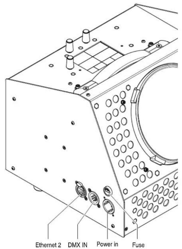
text_image
Ethernet 2 DMX IN Power in FuseControl panel - Fig. 3
3.2 Connecting to mains supply

text_image
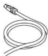
Diagram illustrating three-step installation of a mechanical component with labeled parts and directional arrowsConnecting and disconnecting power cable - Fig. 4
text_image
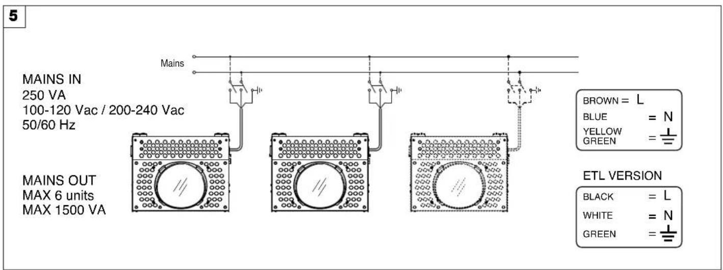
5 MAINS IN 250 VA 100-120 Vac / 200-240 Vac 50/60 Hz MAINS OUT MAX 6 units MAX 1500 VA Mains BROWN = L BLUE = N YELLOW = GREEN = ETL VERSION BLACK = L WHITE = N GREEN =Connecting to the mains supply - Fig. 5
3.3 DMX 512 connections
6
flowchart
graph LR
    A["Controller"] -->|IN| B["Measurement 1"]
    B --> C["Measurement 2"]
    C --> D["Measurement 3"]
    D --> E["Measurement 4"]
    E --> F["Output"]
    style A fill:#f9f,stroke:#333
    style F fill:#f9f,stroke:#333
text_image
COMMON DMX - DMX + Not Used Not Used DMX OUTPUTDMX INPUT DMX 512 5 PIN SCREEN - SIGNAL + SIGNALDMX connections - Fig. 6
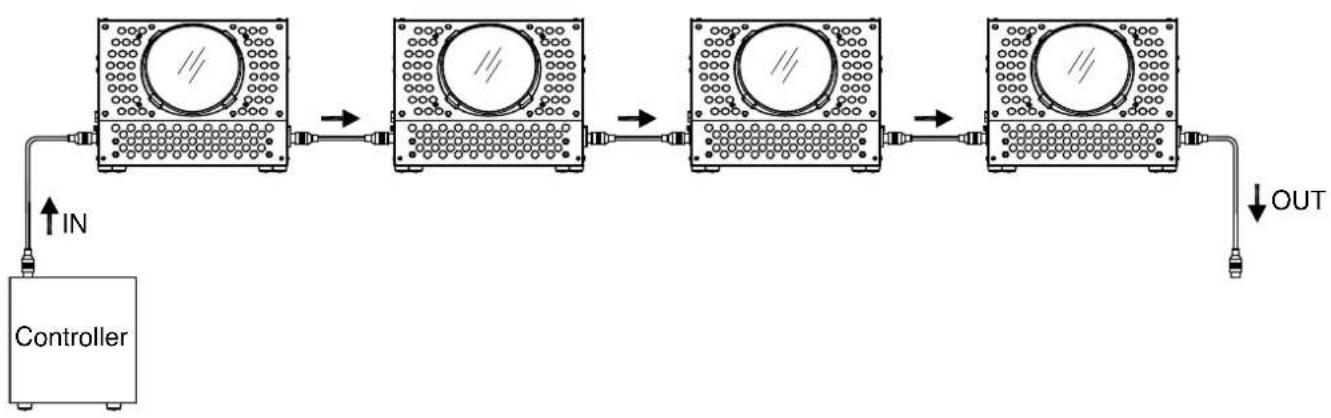
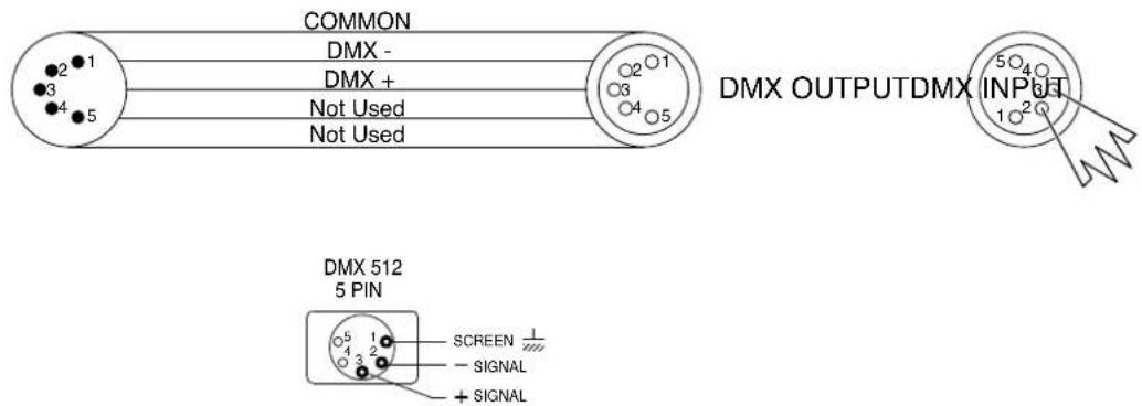
- Use a cable conforming to specifications EIA RS-485: 2-pole twisted, shielded, 120Ohm characteristic impedance, 22-24 AWG, low capacity. Do not use microphone cable or other cable with characteristics differing from those specified. The end connections must be made using XLR type 5-pin male/female connectors. A terminating plug must be inserted into the last projector with a resistance of 120Ohm (minimum 1/4 W) between terminals 2 and 3.
IMPORTANT: The wires must not make contact with each other or with the metal casing of the connectors. The casing itself must be connected to the shield braid and to pin 1 of the connectors. - Connect the fixture together in a "daisy chain" by XLR plug cable from the output of the fixture to the input of the next fixture. The cable cannot be branched or split to a "Y" cable. Inadequate or damaged cables, soldered joints or corroded connectors can easily distort the signal and shut down the system.
- The DMX output and input connectors are pass-through to maintain the DMX circuit when one of the units' power is disconnected.
- Each lighting fixture needs to have an address set to receive the data sent by the controller. The address number is between 1-512.
- 5 pin XLR: Pin 1: GND, Pin 2: Negative signal (-), Pin 3: Positive signal (+), Pin4, Pin5 not used
3.4 Lamp Hook Installation
3.4.1 Introduction
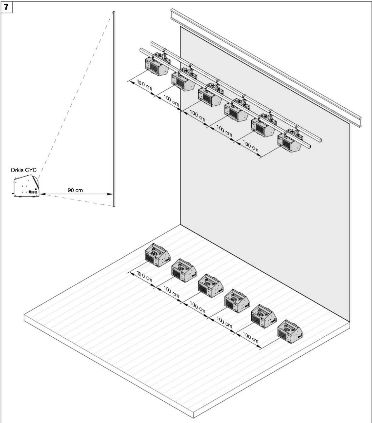
The Orkis CYC has been designed to respond to the increasing need to illuminate walls, scenery and cycloramas uniformly with a smooth, even wash of seamlessly blended colours. The Orkis CYC ensures good colour consistency and uniform light distribution on very high scenery, even when the lighting fixture and the projection surface are very close together.
3.4.2 Installation configurations
The Orkis CYC has been designed to work in a linear set-up, so the fixtures must be aligned in a continuous row. The distance between one fixture and the next one is 1000mm, related to the center of the lens.
text_image
7 Orkis CYC 90 cm 10.0 cm 100 cm 100 cm 100 cm 100 cm 100 cm 100 cm 100 cm 100 cm 100 cmOrkis CYC installation - Fig. 7
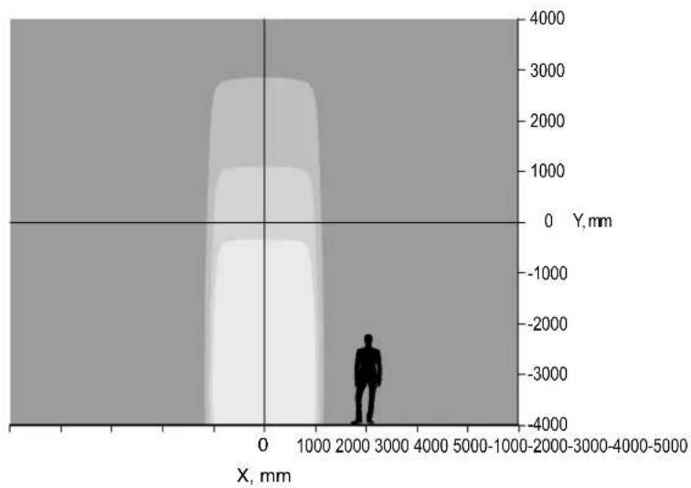
Top and bottom configuration.
Orkis CYC units may be installed in a bottom, top and bottom, or top only set-up, depending on the height of the surface to be lit and on the required effect (total evenness of the light on the cyclorama or a linearly fading intensity effect).
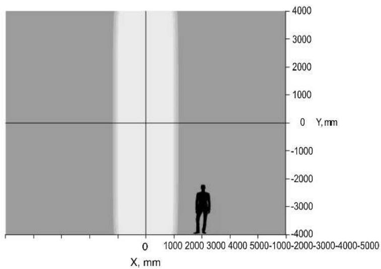
When Orkis CYC units are installed in a single row (top or bottom), they create a uniform horizontal light distribution which fades vertically (see Fig. 1). When they are installed on the floor and on the ceiling (top and bottom rows) at the same distance from the cyclorama, they create an outstandingly uniform vertical light distribution (see Fig. 2). Top and bottom set-up is ideal in order to achieve the most even light distribution on the cyclorama.
8
bar
| X, mm | Y, mm | |-------|-------| | 0 | 0 | | 1000 | 1000 | | 2000 | 2000 | | 3000 | 3000 | | 4000 | 4000 |Figure 1
scatter
| X, mm | Y, mm | |-------|-------| | 2000 | -3000 |Figure 2
top and bottom row setup
Orkis CYC' performance with different installation configurations
4. TROUBLESHOOTING
Following are a few common problems that may occur during operation. Here are some suggestions for easy troubleshooting:
A. The unit does not work, no light and the fan does not work
- Check the connection of power and main fuse.
- Measure the mains voltage on the main connector.
- Check the power on Fixture.
B. Not responding to DMX controller
- Check DMX connectors, cables to see if link properly.
- No response to the channel, check the address settings and DMX polarity.
- If you have intermittent DMX signal problems, check the pins on connectors or on PCB of the unit or the previous one.
- Try to use another DMX controller.
- Check if the DMX cables run near or run alongside to high voltage cables that may cause damage or interference to DMX interface circuit.
5. FIXTURE CLEANING
The cleaning of internal and external optical lenses and/or mirrors must be carried out periodically to optimize light output.
Cleaning frequency depends on the environment in which the fixture operates: damp, smoky or particularly dirty surrounding can cause greater accumulation of dirt on the unit's optics.
- Clean with soft cloth using normal glass cleaning fluid.
• Always dry the parts carefully. - Clean the external optics at least every 20 days. Clean the internal optics at least every 30/60 days.
9
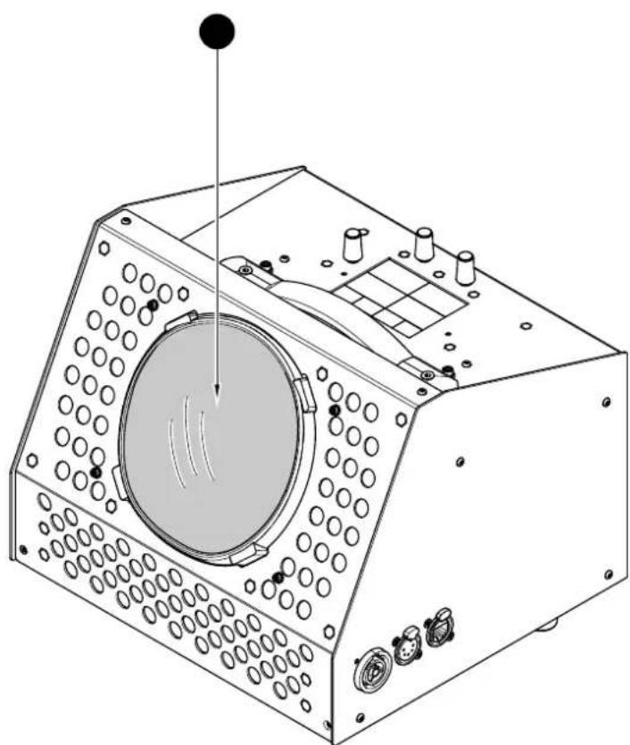
natural_image
Technical line drawing of a mechanical device with circular components and a central dial (no text or symbols)6. DIMENSIONS
