HOLHD16002 - Security Camera Holis - Free user manual and instructions
Find the device manual for free HOLHD16002 Holis in PDF.

User questions about HOLHD16002 Holis
0 question about this device. Answer the ones you know or ask your own.
Ask a new question about this device
Download the instructions for your Security Camera in PDF format for free! Find your manual HOLHD16002 - Holis and take your electronic device back in hand. On this page are published all the documents necessary for the use of your device. HOLHD16002 by Holis.
USER MANUAL HOLHD16002 Holis
natural_image
Green circular icon with a white stylized 'H' symbol in the center (no text or numbers)HOLIS
From Tyco Security Products
Holis HD Series DVR
User Manual
4, 8 & 16 Channel Models
Notice
Please read this manual thoroughly and save it for future use before attempting to connect or operate this unit.
The information in this manual was current when published. The manufacturer reserves the right to revise and improve its products. All specifications are therefore subject to change without notice.
Copyright
Under copyright laws, the contents of this manual may not be copied, photocopied, reproduced, translated or reduced to any electronic medium or machine-readable form, in whole or in part, without prior written consent of Tyco Security Products. © 2016 Tyco Security Products. All rights reserved.
Customer Service
Thank you for using Tyco Security Products. We support our products through an extensive worldwide network of dealers. The dealer through whom you originally purchased this product is your point of contact if you need service or support. Our dealers are empowered to provide the very best in customer service and support. Dealers should contact Tyco Security Products at (800) 507-6268 or (561) 912-6259 or on the Web at www.holisnvr.com
Trademarks
The trademarks, logos, and service marks displayed on this document are registered in the United States [or other countries]. Any misuse of the trademarks is strictly prohibited and Tyco Security Products. will aggressively enforce its intellectual property rights to the fullest extent of the law, including pursuit of criminal prosecution wherever necessary. All trademarks not owned by Tyco Security Products. are the property of their respective owners, and are used with permission or allowed under applicable laws.
Product offerings and specifications are subject to change without notice. Actual products may vary from photos. Not all products include all features. Availability varies by region; contact your sales representative.
Table of Contents
FEATURES AND SPECIFICATIONS .... 1
Overview .... 1
Features .... 1
OVERVIEW AND CONTROLS....3
Front Panel....3
4 Channel/8Channel Holis HD DVR 3
Rear Panel....3
8 Channel Holis HD DVR....3
Connection Sample....5
16 Channel Holis HD DVR....5
Mouse Control 5
INSTALLATION AND CONNECTIONS....7
Check Unpacked DVR....7
About Front Panel and Rear Panel....7
HDD Installation 7
Holis HD 7
Connecting Power Supply 8
Connecting Video Input and Output Devices....8
Connecting Video Input 8
Connecting Video Output....9
Connecting Audio Input & Output, Bidirectional Audio....9
Audio Input....9
Audio Output....9
Alarm Input and Output Connection 9
Alarm Input and Output Details....10
Alarm Input Port....11
Alarm Output Port 11
RS485 12
Other Interfaces....12
OVERVIEW OF NAVIGATION AND CONTROLS.... 13
Boot up and Shutdown....13
Boot up....13
Shutdown....13
Auto Resume after Power Failure....13
Change/Reset Password 13
Change Password 13
Startup Wizard....14
Live Viewing 19
Right-Click Menu....21
Window Switch....22
Previous Screen/Next Screen....22
PTZ Control....22
PTZ Function Setup....24
Call PTZ Function....26
Color 27
Display 28
Navigation Bar....29
Main Menu 29
Output Screen 29
Previse screen 29
Next Screen 29
Tour....29
Favorites 30
Channel....30
PTZ 30
Color 30
Search....30
Alarm Status 30
Channel Info....30
Remote Device 31
Network....31
HDD Manager 31
USB Manager 31
USB Device Auto Pop-up 31
Main Menu....31
Operation 32
Search....32
Smart Search....36
Accurate playback by time 37
Mark Playback....37
Customized Playback 39
Splice Playback 39
Backup 40
Shut Down 42
Information....43
System Info 43
HDD Information....43
Record Info 45
Record Estimate 45
BPS 48
Version 48
Event 49
Network....49
Online Users....50
Network Load 50
Network Test 51
Log 52
Setting 53
Camera 53
Remote Device (For digital channel only) 54
Image....59
Encode 61
Network....67
TCP/IP 67
Connection 68
PPPoE 69
DDNS Setup....70
IP Filter 72
Email....73
FTP 74
UPnP 76
SNMP 77
Multicast 78
P2P 80
Event....81
Detect 81
Alarm 89
Abnormality....95
Alarm Output 97
Storage 98
Schedule....98
HDD Manager....105
Record 105
HDD Detect 107
System....109
General....110
Display....113
Video Matrix....116
PTZ....118
ATM/POS 120
Voice....121
Account....122
Auto Maintain....128
Config Backup 128
Default 129
Update 130
Network Connection....132
Login....132
LAN Mode....133
Live 135
PTZ....135
Image 136
Image 136
WAN Login....137
Setup 138
Camera 138
Remote Device....138
Conditions....140
Encode 143
Channel Name....146
Channel Type 146
Network....147
TCP/IP 147
Connection 148
PPPoE 149
DDNS 149
IP filter 150
Email....151
FTP 152
UPnP 153
SNMP 154
Multicast 155
Auto Register....155
Alarm Centre 156
P2P 156
HTTPS....156
Event....161
Video detect....161
Alarm 166
Abnormality....169
Storage 171
Schedule....171
Local Storage 172
Record 173
Setting....174
General....174
Display....176
Video Matrix....178
PTZ....179
ATM/POS 180
Account....181
Auto maintain....186
Import/Export 186
Default 186
Upgrade 187
Information....187
Version....187
Log....187
Online User....188
HDD 189
Playback....189
Search Record....190
File List....191
Playback 192
Download....192
Load more....193
Download By File....193
Download by Time....194
Watermark....195
Alarm 195
Log out....196
Un-install Web Control 197
FAQ....198
Important Safeguards and Warnings
1. Electrical safety
All installation and operation here should conform to your local electrical safety codes.
The product must be grounded to reduce the risk of electric shock.
We assume no liability or responsibility for all the fires or electrical shock caused by improper handling or installation.
2. Transportation security
Heavy stress, violent vibration or water splash are not allowed during transportation, storage and installation.
3. Installation
Keep upwards. Handle with care.
Do not apply power to the DVR before completing installation.
Do not place objects on the DVR
4. Qualified engineers needed
All the examination and repair work should be done by the qualified service engineers.
We are not liable for any problems caused by unauthorized modifications or attempted repair.
5. Environment
The DVR should be installed in a cool, dry place away from direct sunlight, inflammable, explosive substances and etc.
This series product shall be transported, storage and used in the specified environments.
6. Accessories
Be sure to use all the accessories recommended by manufacturer.
Before installation, please open the package and check all the components are included.
Contact your local retailer ASAP if something is broken in your package.
©
Holis HD Series DVR User Manual 4, 8 & 16 Channel Models
● Network operation
Support network remote real-time monitor, remote record search and remote PTZ control.
- Alarm activation function
Several relay alarm outputs to realize alarm activation and on-site light control.
The alarm input port and output has the protection circuit to guarantee device safety.
- Communication port
RS485 port can realize alarm input and PTZ control.
RS232 port can connect to keyboard to realize central control, and can also connect to PC COM to upgrade system and realize maintenance, and matrix control.
Standard Ethernet port can realize network access function.
- PTZ control
Support PTZ decoder via RS485.
Support various decode protocols to allow the PTZ to control the speed dome.
- Intelligent operation
Mouse operation function
In the menu, support copy and paste setup function
- UPnP
It is to establish the mapping relationship between the LAN and the WAN via the UPnP protocol.
Slight function differences may be found due to different series.
Overview and Controls
This section provides information about front panel and rear panel. When you install this series DVR for the first time, please refer to this part first.
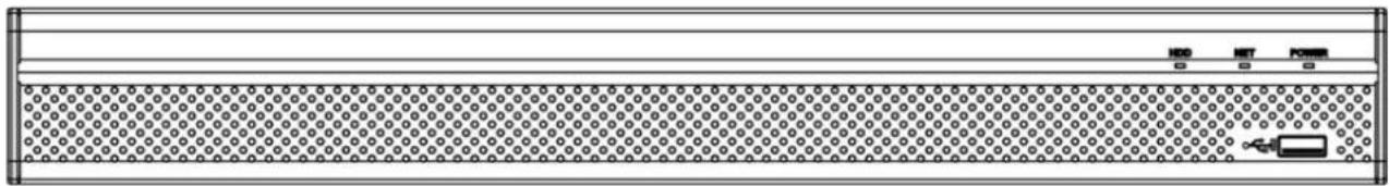
Front Panel
4 Channel/8Channel Holis HD DVR
The front panel is shown as below. See Figure 2-1.
text_image
HDD NET POWER 0 0 0Figure 2-1
Please refer to the following sheet for front panel button information.
| Icon | Name | Function |
| HDD | HDD status indicator light | The blue light is on when the HDD is malfunction. |
| NET | Network status indicator light | The blue light is on when the network connection is abnormal. |
| POWER | Power status indicator light | The blue light is on when the power connection is OK. |
| USB2.0 port | Connect to peripheral USB 2.0 storage device, mouse, burner and etc. |
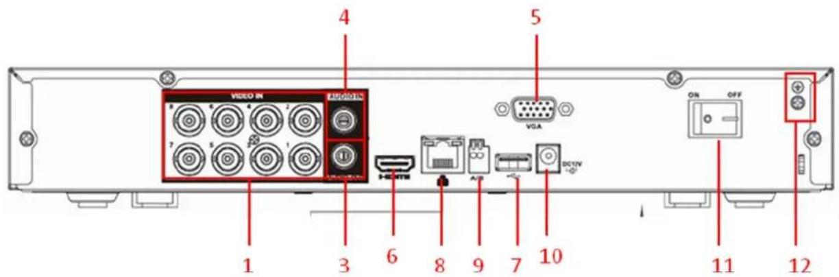
Rear Panel
8 Channel Holis HD DVR
The 8 channel Holis HD rear panel is shown as below. See Figure 2-2.
The 4 channel Holis HD rear panel is identical with the exception of having only 4 video inputs.
text_image
VIDEO IN AUDIO IN VGA ON OFF 1 3 6 8 9 7 10 11 12Figure 2-2
| SN | Name | SN | Name | SN | Name |
| 1 | Video input | 3 | Audio output | ||
| 4 | Audio input | 5 | Video VGA output | 6 | HDMI port |
| 7 | USB port | 8 | Network port | 9 | RS-485 input port |
| 10 | Power socket | 11 | On/Off button | 12 | GND port |
Please refer to the following for detailed information.
| SN | Icon | Name | Note |
| 1 | VIDEO IN | Video input port | Connect to analog camera, video input signal. |
| 3 | AUDIO output | Audio output port | Connect to audio output device such as speaker. |
| 4 | AUDIO Input | Audio input port | Connect to audio input device such as a microphone. |
| 5 | VGA | VGA video output port | VGA video output port. Output analog video signal. Can connect to the monitor to view ananlog video output. |
| 6 | HDMI | High definition media interface | High definition audio and video signal output port. It transmits uncompressed high definition video and multiple-channel data to the HDMI port of the display device. |
| 7 |  | USB2.0 port | Connect to USB storage device, mouse, burning DVD-ROM and etc. |
| 8 |  | Network port | 100M Ethernet port |
| 9 | A | RS485 (RS-485) communication port | RS485_A port. It is the cable A. You can connect to the control devices such as speed dome PTZ. |
| B | RS485_B.It is the cable B. You can connect to the control devices such as speed dome PTZ. | ||
| 10 |  | Power input port | Input 12V DC. |
| 11 | 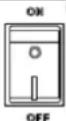 | Power on-off button | Power on/off button. |
| 12 | [70CC] | GND | Ground Bus |
Connection Sample
16 Channel Holis HD DVR
Please refer to Figure 2-3 for connection sample. The following figure is based on 16-channel Holis HD with 16 audio inputs. The standard 16 channel Holis HD DVR is equipped with 4 audio inputs.
text_image
Alarm Input Alarm Output Video Input Audio Input VGA Output GND Power Switch USB Port Power Socket Power Cable Fastener Audio Output HDMI Output PTZ RS485 Output Network Switch Network User Network User Network User Network KeyboardFigure 2-3
Mouse Control
| Left click mouse | System pops up password input dialogue box if you have not logged in. In real-time monitor mode, you can go to the main menu. |
| When you have selected one menu item, left click mouse to view menu content. | |
| Implement the control operation. | |
| Modify checkbox or motion detection status. | |
| Click combo box to pop up drop down list | |
In input box, you can select input methods. Left click the corresponding button on the panel you can input numeral/English character (small/capitalized). Here← stands for backspace button. _ stands for space button.In English input mode: _stands for input a backspace icon and ← stands for deleting the previous character.  In numeral input mode: _stands for clear and ← stands for deleting the previous numeral.When input special sign, you can click corresponding numeral in the front panel to input. For example, click numeral 1 you can input“/”, or you can click the numeral in the on-screen keyboard directly. In numeral input mode: _stands for clear and ← stands for deleting the previous numeral.When input special sign, you can click corresponding numeral in the front panel to input. For example, click numeral 1 you can input“/”, or you can click the numeral in the on-screen keyboard directly. | |
| Double left click mouse | Implement special control operation such as double click one item in the file list to playback the video. |
| In multiple-window mode, double left click one channel to view in full-window.Double left click current video again to go back to previous multiple-window mode. | |
| Right click mouse | In real-time monitor mode, pops up shortcut menu: one-window, four-window, nine-window and sixteen-window, Pan/Tilt/Zoom, color setting, search, record, alarm input, alarm output, main menu.Among which, Pan/Tilt/Zoom and color setting applies for current selected channel.If you are in multiple-window mode, system automatically switches to the corresponding channel.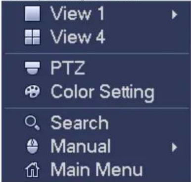 |
| Exit current menu without saving the modification. | |
| Press middle button | In numeral input box: Increase or decrease numeral value. |
| Switch the items in the check box. | |
| Page up or page down | |
| Move mouse | Select current control or move control |
| Drag mouse | Select motion detection zone |
| Select privacy mask zone. |
Installation and Connections
Note: All the installation and operations here should conform to your local electric safety rules.
Check Unpacked DVR
When you receive the DVR from the forwarding agent, please check whether there is any visible damage. The protective materials used for the package of the DVR can protect most accidental clashes during transportation. Then you can open the box to check the accessories.
Please check the items in accordance with the list. Finally you can remove the protective film of the DVR.
About Front Panel and Rear Panel
The model label in the front panel is very important; please check according to your purchase order. The label in the rear panel is very important too. Usually we need you to represent the serial number when we provide the service after sales.
HDD Installation

Important
Shut down the device and then unplug the power cable before you open the case to replace the HDD!
All figures listed below for reference only!
You can refer to the Appendix for recommended HDD brand. Please use HDD of 7200rpm or higher. Please follow the instructions below to install hard disk.
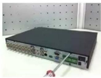
Holis HD
The series DVR has one SATA HDD.
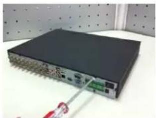
natural_image
Close-up of a black networking device with ports and connectors, placed on a white surface with a red cable inserted (no visible text or symbols)- Loosen the screws of the upper cover and side panel.

natural_image
Close-up of a hand holding an open hard disk with visible circuit board and drive slots (no text or symbols)- Fix four screws in the HDD (Turn just three rounds).

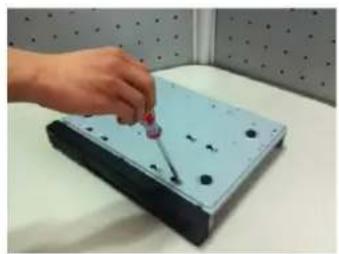
natural_image
Close-up of a hand inserting a CD into an open computer drive (no visible text or labels)- Place the HDD in accordance with the four holes in the bottom.

natural_image
Exterior view of a rectangular electronic device with mounting holes and a reflective surface (no text or symbols visible)- Turn the device upside down and then turn the screws in firmly.
natural_image
Hand placing a purple object onto a light blue electronic device with black holes, placed on a white surface against a dotted wall (no text or symbols visible)- Fix the HDD firmly.
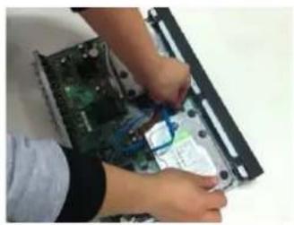
natural_image
Person working on a computer motherboard with a plastic clip and paper clip (no visible text or symbols)- Connect the HDD cable and power cable.

natural_image
Black rectangular electronic device with a small slot, placed on a white surface with a perforated background (no text or symbols visible)- Put the cover in accordance with the clip and then place the upper cover back.
natural_image
Close-up of a black server rack with ports and a hand holding a cable, placed on a white surface against a perforated wall (no visible text or symbols)- Secure the screws in the rear panel and the side panel.
Important:
- You can connect the HDD data cable and the power cable first and then fix the HDD in the device.
- Please pay attention to the front cover. It adopts the vertical sliding design. You need to push the clip first and then put down.
Connecting Power Supply
Please check input voltage and device power button match or not.
We recommend you use UPS to guarantee steady operation, DVR life span, and other peripheral equipments operation such as cameras.
Connecting Video Input and Output Devices
Connecting Video Input
The video input interface is BNC. The input video format includes: PAL/NTSC BNC (1.0V _P-P 75Ω.) The video signal should comply with your national standards.
The input video signal shall have high SNR, low distortion; low interference, natural color and suitable lightness
Guarantee the stability and reliability of the camera signal:
The camera shall be installed in a cool, dry place away from direct sunlight, inflammable, explosive substances and etc.
The camera and the DVR should have the same grounding to ensure the normal operation of the camera.
Guarantee stability and reliability of the transmission line
Please use high quality, sound shielded BNC. Please select suitable BNC model according to the transmission distance.
If the distance is too long, you should use twisted pair cable, and you can add video compensation devices or use optical fiber to ensure video quality.
You should keep the video signal away from the strong electromagnetic interference, especially the high tension current.
Keep connection lugs in well contact
The signal line and shielded wire should be fixed firmly and in well connection. Avoid dry joint, lap welding and oxidation
Connecting Video Output
Video output includes a BNC(PAL/NTSC1.0V _P-P , 75Ω) output, a VGA output and HDMI output. System supports BNC, VGA and HDMI output at the same time. you are using pc-type monitor to replace the monitor, please pay attention to the following points:
● To defer aging, do not allow the pc monitor to run for a long time.
● Regular demagnetization will keep device maintain proper status.
- Keep it away from strong electromagnetic interference devices.
Using TV as video output device is not a reliable substitution method. You also need to reduce the working hour and control the interference from power supply and other devices. The low quality TV may result in device damage.
Connecting Audio Input & Output, Bidirectional Audio
Audio Input
These series products audio input port adopt BNC port.
Due to high impedance of audio input, please use active sound pick-up.
Audio transmission is similar to video transmission. Try to avoid interference, dry joint, loose contact and it shall be away from high tension current.
Audio Output
audio output signal parameter is usually over 200mv 1KΩ (BNC or RCA). It can directly connect to low impedance earphone, active sound box or amplifier-drive audio output device.
If the sound box and the pick-up cannot be separated spatially, it is easy to arouse squeaking.this case you can adopt the following measures:
- Use better sound pick-up with better directing property.
- Reduce the volume of the sound box.
- Using more sound-absorbing materials in decoration can reduce voice echo and improve acoustics environment.
Alarm Input and Output Connection
Please read the followings before connecting.
1. Alarm input
a. Please make sure alarm input mode is grounding alarm input
b. Grounding signal is needed for alarm input.
c. Alarm input needs the low level voltage signal.
d. Alarm input mode can be either NC (normal Open) or NO (Normal Close)
e. When you are connecting two DVRs or you are connecting one DVR and one other device, please use a relay to separate them
- Alarm output The alarm output port should not be connected to high power load directly (It shall be less than 1A) to avoid high current which may result in relay damage. Please use the co contactor to realize the connection between the alarm output port and the load.
3. How to connect PTZ decoder
a. Ensure the decoder has the same grounding with DVR, otherwise you may not control the PTZ.
Shielded twisted wire is recommended and the shielded layer is used to connect to the grounding.
b. Avoid high voltage. Ensure proper wiring and some thunder protection measures.
. For too long signal wires, 120Ω should be parallel connected between A, B lines on the far end to reduce reflection and guarantee the signal quality.
d.485 A, B" of DVR cannot parallel connect with "485 port" of other device.
e. The voltage between of A,B lines of the decoder should be less than 5v.
- Please make sure the front-end device has soundly earthed.
Improper grounding may result in chip damage.
Alarm Input and Output Details
Important
Please refer to the specifications for the alarm input and output channel amount. Do not merely count the alarm input and out channel amount according to the ports on the rear panel.
The following interface is based on the 8-channel advanced 1080P (V2) mini 1U Series. See Figure 3-1.

text_image
NO3C2 NO2 16 15 14 13 ± 12 11 10 9 C3 C1 NO1 8 7 6 5 ± 4 3 2 1Figure 3-1
| 1, 2, 3, 4, 5,6, 7, 8, 9, 10,11, 12, 13, 14,15, 16 | ALARM 1 to ALARM 16. The alarm becomes active in low voltage. |
| NO1 C1, NO2 C2,NO3 C3, | Three normal open groups (on/off signal) |
| Earth cable. |
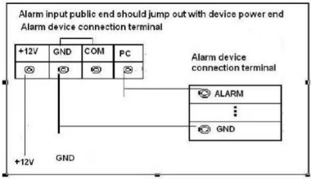
Alarm Input Port
Please refer to the following sheet for more information.
● Grounding alarm inputs. Normal open or Normal close type)
- Please parallel connect COM end and GND end of the alarm detector (Provide external power to the alarm detector).
- Please parallel connect the Ground of the DVR and the ground of the alarm detector.
- Please connect the NC port of the alarm sensor to the DVR alarm input(ALARM)
- Use the same ground with that of DVR if you use external power to the alarm device.
flowchart
graph TD
    A["+12V"] --> B["GND"]
    C["+12V"] --> D["GND"]
    E["+12V"] --> F["COM"]
    G["PC"] --> H["COM"]
    I["PC"] --> J["COM"]
    K["ALARM"] --> L["GND"]
    M["..."] --> N["GND"]
Figure 3-2
Alarm Output Port
● Provide external power to external alarm device.
● To avoid overloading, please read the following relay parameters sheet carefully.
● RS485 A/B cable is for the A/B cable of the PTZ decoder.
● T+,T-,R+,R- are four-wire double duplex RS485 port.
T+ T-: output wire
R+ R-: input wire
Relay Specification
| Model: JRC-27F | ||
| Material of the touch | Silver | |
| Rating (Resistance Load) | Rated switch capacity 30VDC 2A, 125VAC 1A | |
| Maximum switch power 125VA | 160W | |
| Maximum switch voltage 250VA | C, 220VDC | |
| Maximum switch currency 1A | ||
| Insulation | Between touches with same polarity | 1000VAC 1minute |
| Between touches with different polarity | 1000VAC 1minute | |
| Between touch and winding | 1000VAC 1minute | |
| Surge voltage | Between touches with same polarity | 1500V (10×160us) |
| Length of open time | 3ms max | |
| Length of close time | 3ms max | |
| Longevity | Mechanical 50×106 times (3Hz) | |
| Electrical 200×103 times (0.5Hz) | ||
| Temperature | -40°C~+70°C | |
RS485
When the DVR receives a camera control command, it transmits that command up the coaxial cable to the PTZ device. RS485 is a single-direction protocol; the PTZ device can't return any data to the unit. To enable the operation, connect the PTZ device to the RS485 (A,B) input on the DVR.
Since RS485 is disabled by default for each camera, you must enable the PTZ settings first. This series DVRs support multiple protocols such as Pelco-D, Pelco-P.
To connect PTZ devices to the DVR:
- Connect RS485 A,B on the DVR rear panel.
- Connect the other end of the cable to the proper pins in the connector on the camera.
- Please follow the instructions to configure a camera to enable each PTZ device on the DVR.
Other Interfaces
There are still other interfaces on the DVR, such as USB port.
Overview of Navigation and Controls
Boot up and Shutdown
Boot up
Before the boot up, please make sure:
- The rated input voltage matches the device power on-off button. Please make sure the power wire connection is OK. Then click the power on-off button.
● Always use the stable current, if necessary UPS is a best alternative measure.
Please follow the steps listed below to boot up the device. - Connect the device to the monitor and then connect a mouse.
- Connect power cable.
- Click the power button at the front or rear panel and then boot up the device. After device booted up, the system is in multiple-channel display mode by default.
Shutdown
Note
- When you see corresponding dialogue box "System is shutting down..." Do not click power on-off button directly.
- Do not unplug the power cable or click power on-off button to shutdown device directly when device is running (especially when it is recording.)
There are three ways for you to log out.
a) Main menu (RECOMMENDED)
From Main Menu->Shutdown, select shutdown from dropdown list.
Click OK button, you can see device shuts down.
b) From power on-off button on the front panel or remote control
Press the power on-off button on the DVR front panel or remote control for more than 3 seconds to shutdown the device.
c) From power on-off button on the rear panel.
Auto Resume after Power Failure
The system can automatically backup video and resume previous working status after power failure.
Change/Reset Password
Change Password
For your own safety, please change your administrator default password after your first login.
After system booted up, you can see the following interface if it is your first login or you have restored default setup. See Figure 4-1. Please input old password and then input new password twice to confirm the change.
● The default administrator user name is admin and the password is admin.

text_image
ADMIN SECURITY User Name admin Old Password New Password Confirm Password Secure Question Question 1 What's your favorite pet? Answer Question 2 What's your first car model? Answer OK CancelFigure 4-1
Click Cancel button, system pops up the following interface for you to confirm. See Figure 4-2. Check the box here, system will not pop up the change password interface the next time.
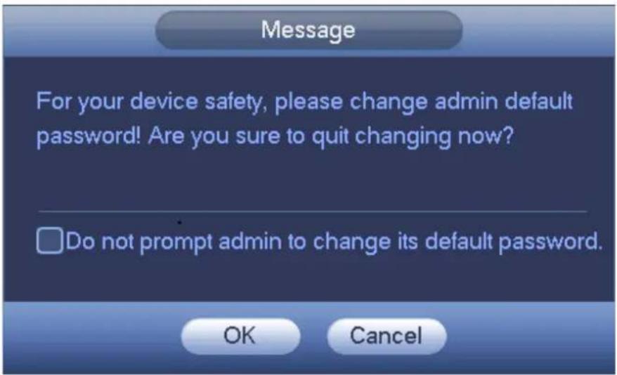
text_image
Message For your device safety, please change admin default password! Are you sure to quit changing now? Do not prompt admin to change its default password. OK CancelFigure 4-2
Startup Wizard
After device successfully booted up, it goes to startup wizard.
Click Cancel/Next button, you can see system goes to login interface.
Tips
Check the box Startup button here, system goes to startup wizard again when it boots up the next time. Cancel the Startup button, system goes to the login interface directly when it boots up the next time.

text_image
Startup Wizard Welcome to use startup wizard. This startup wizard will help you set parameters. Click Next to continue. Startup Next CancelFigure 4-3
Click Cancel button or Next Step button, system goes to login interface. See Figure 4-4.
System consists of three accounts:
- Username: admin. Password: admin. (administrator, local and network)
- Username: default. Password: default (hidden user). Hidden user "default" is for system interior use only and can not be deleted. When there is no login user, hidden user "default" automatically login. You can set some rights such as monitor for this user so that you can view some channel view without login.
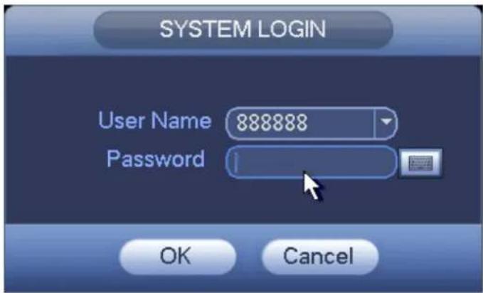
text_image
SYSTEM LOGIN User Name 888888 Password OK CancelFigure 4-4
Note:
For security reason, please modify password after you first login.
Within 30 minutes, three times login failure will result in system alarm and five times login failure will result in account lock!
Click OK button, you can go to General interface. See Figure 4-5.

text_image
GENERAL General Date&Time Holiday Device Name HCVR Device No. 8 Language ENGLISH Video Standard PAL HDD Full Overwrite Pack Mode Time Length 60 min. Realtime Play 5 min. Auto Logout 10 min. IPC Time Sync 24 h Navigation Bar Mouse Sensitivity Slow Fast Default Apply Back Next CancelFigure 4-5
Click Next button, you can go to network interface. See Figure 4-6.
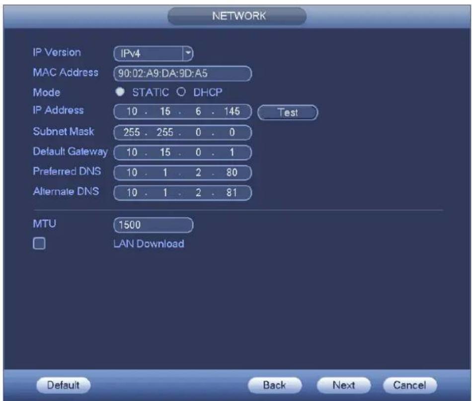
text_image
NETWORK IP Version IPv4 MAC Address 90:02:A9:DA:9D:A5 Mode STATIC DHCP IP Address 10 . 15 . 6 . 145 Test Subnet Mask 255 . 255 . 0 . 0 Default Gateway 10 . 15 . 0 . 1 Preferred DNS 10 . 1 . 2 . 80 Alternate DNS 10 . 1 . 2 . 81 MTU 1500 LAN Download Default Back Next CancelFigure 4-6
Holis HD Series DVR User Manual 4, 8 & 16 Channel Models
Click Next button, you can set P2P function. Scan the QR code, download the App to the cellphone, you can use the smart phone to add the device. See Figure 4-7.
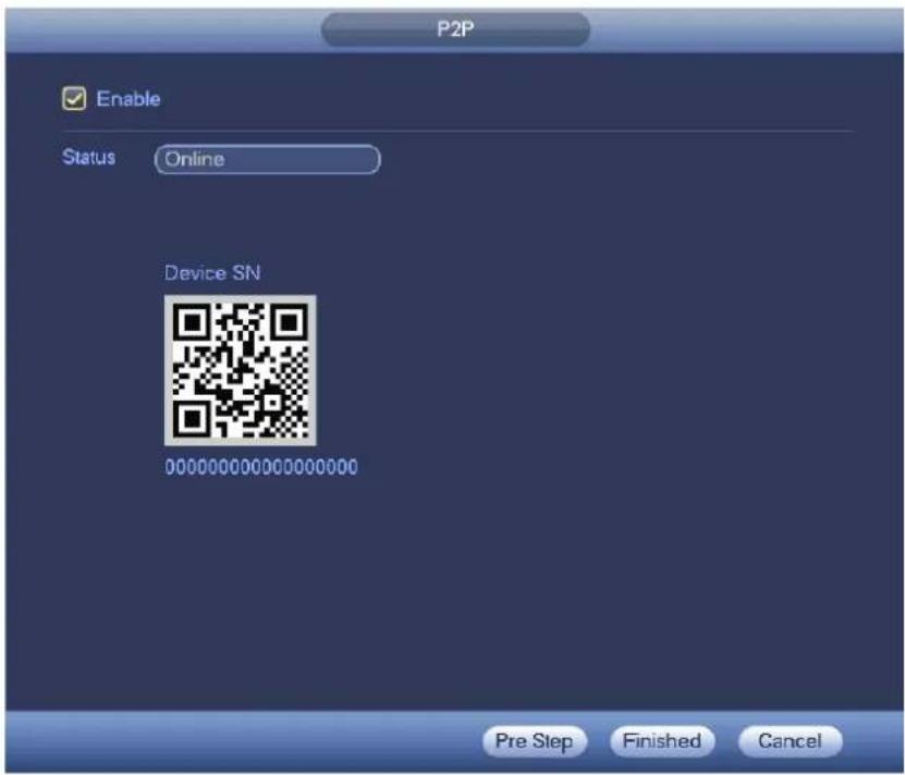
text_image
P2P Enable Status Online Device SN 00000000000000000 Pre Step Finished CancelFigure 4-7
Now you can go to the remote device interface to add the camera to the corresponding channel. See Figure 4-8.
Please note you can not see the following interface if there is no digital channel. You can go to Main menu->Setting->Camera->Channel type to set IP channel first.

text_image
REMOTE DEVICE 0 Edit IP Address Manufacturer Type IP Search Add Manual Add Show Filter IPC Added Device Channel Edit Delete Status IP Address Port Device Nam Delete Export Import Back Next CancelFigure 4-8
Holis HD Series DVR User Manual 4, 8 & 16 Channel Models
Click Next button, you can go to Encode interface. See Figure 4-9.
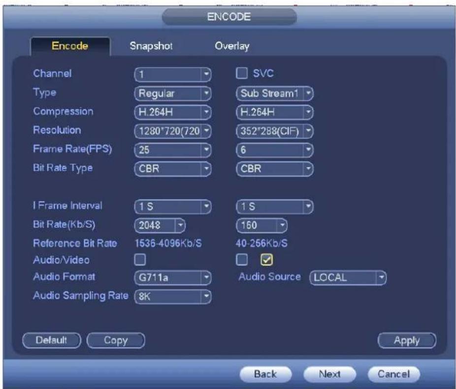
text_image
ENCODE Encode Snapshot Overlay Channel 1 Type Regular Compression H.264H Resolution 1280°720(720) Frame Rate(FPS) 25 Bit Rate Type CBR I Frame Interval 1 S Bit Rate(Kb/S) 2048 Reference Bit Rate 1536-4096Kb/S Audio/Video Audio Format G711a Audio Sampling Rate 8K SVC Sub Stream1 H.264H 352°288(CIF) 6 CBR 1 S 160 40-256Kb/S Audio Source LOCAL Default Copy Apply Back Next CancelFigure 4-9
Click Next button, you can go to Schedule interface. See Figure 4-10.
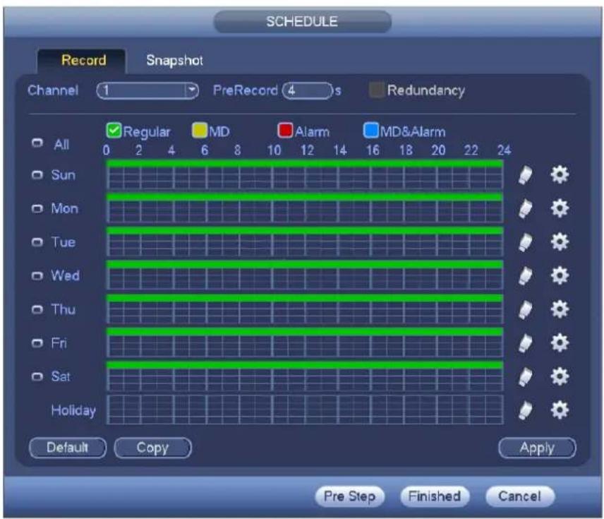
text_image
SCHEDULE Record Snapshot Channel 1 PreRecord 4 s Redundancy All 0 2 4 6 8 10 12 14 16 18 20 22 24 Sun Mon Tue Wed Thu Fri Sat Holiday Default Copy Apply Pre Step Finished CancelFigure 4-10
Holis HD Series DVR User Manual 4, 8 & 16 Channel Models
Click Finish button, system pops up a dialogue box. Click the OK button, the startup wizard is complete. See Figure 4-11.

text_image
Message Thank you for purchasing our product! OKFigure 4-11
Live Viewing
After you logged in, the system is in live viewing mode. You can see system date, time, channel name and window No. If you want to change system date and time, you can refer to general settings (Main Menu->Setting->System->General). If you want to modify the channel name, please refer to the display settings (Main Menu->Camera->CAM name).
| 1 | Recording status 3 | ? | Video loss | ||
| 2 | Motion detection 4 | Camera lock |
Tips
- Preview drag: If you want to change position of channel 1 and channel 2 when you are previewing, you can left click mouse in the channel 1 and then drag to channel 2, release mouse you can switch channel 1 and channel 2 positions.
- Use mouse middle button to control window split: You can use mouse middle button to switch window split amount.
Preview Control
The preview control function has the following features.
● Support preview playback.
In the preview desktop, system can playback previous 5-60 minutes record of current channel. Please go to the Main Menu->General to set real-time playback time.
Support drag and play function. You can use your mouse to select any playback start time.
✦ Support playback, pause and exit function.
Right now, system does not support slow playback and backward playback function.
● Support digital zoom function.
● Support real-time backup function.
You can follow the contents listed below for the operation instruction.
Preview control interface
Move you mouse to the top centre of the video of current channel, you can see system pops up the preview control interface. See Figure 4-12 and Figure 4-13. If your mouse stays in this area for more than 6 seconds and has no operation, the control bar automatically hides.
| 1 | 2 | 3 | 4 | 5 |

text_image
Screenshot of a software toolbar with icons for file, edit, refresh, photo, and audio functionsFigure 4-12 Analog Channel

text_image
1 2 3 4 6 7Figure 4-13 Digital Channel
1) Realtime playback
It is to playback the previous 5-60 minutes record of current channel.
Please go to the Main menu->Setting->->System->General to set real-time playback time.
System may pop up a dialogue box if there is no such record in current channel.
2) Digital zoom
It is to zoom in specified zone of current channel. It supports zoom in function of multiple-channel.
Click button +, the button is shown as.
There are two ways for you to zoom in.
- Drag the mouse to select a zone, you can view an interface show as Figure 4-14.

text_image
HBI HBIFigure 4-14
- Put the middle button at the centre of the zone you want to zoom in, and move the mouse, you can view an interface shown as in Figure 4-15.
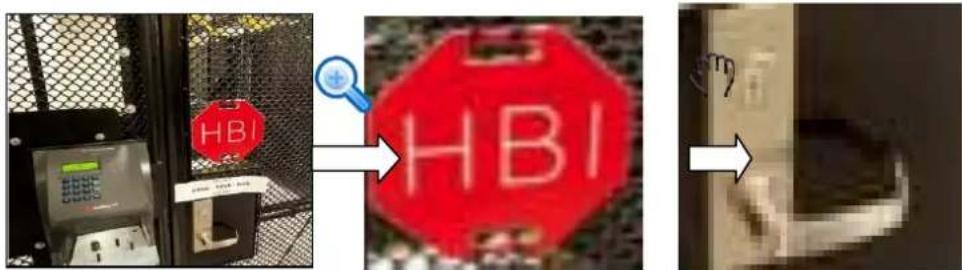
text_image
HBI HBIFigure 4-15
Right click mouse to cancel zoom and go back to the original interface.
3) Manual record function
It is to backup the video of current channel to the USB device. System can not backup the video of multiple-channel at the same time.
Holis HD Series DVR User Manual 4, 8 & 16 Channel Models
Click button, system begins recording. Click it again, system stops recording. You can find the record file on the flash disk.
4) Manual Snapshot
Click to snapshot 1-5 times. The snapshot file is saved on the USB device or HDD. You can go to the Search interface (chapter 4.9.1) to view.
5) Mute (For analog channel only)
Click to mute. Click again to enable audio function when preview.
Please note this function is for one-window mode only or the max-size window of the 8-window mode.
6) Bidirectional talk (For digital channel only)
If the connected front-end device supports bidirectional talk function, you can click this button. Click
button 📂 to start bidirectional talk function the icon now is shown as 📋. Now the rest bidirectional talk buttons of digital channel becomes null too.
Click 🖼 again, you can cancel bidirectional talk and the bidirectional talk buttons of other digital channels become as 🖼.
7) Remote device (For digital channel only)
Shortcut menu. Click it to go to the remote device interface to add/delete remote device or view its corresponding information. Please refer to chapter 4.11.1.1.1 for detailed information.
Right-Click Menu
On the preview interface, right click mouse, you can view menu interface shown as in Figure 4-16. Tips
After you go to the corresponding interface, right click mouse to go back to the upper-level.
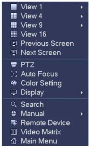
text_image
View 1 View 4 View 9 View 16 Previous Screen Next Screen PTZ Auto Focus Color Setting Display Search Manual Remote Device Video Matrix Main MenuHolis HD Series DVR User Manual 4, 8 & 16 Channel Models
Figure 4-16
Window Switch
System supports 1/4/8/9-window (The options here depend on your product channel amount). You can select from the dropdown list. See Figure 4-17.
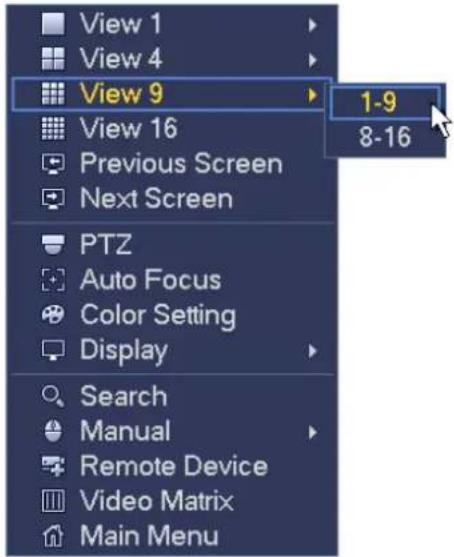
text_image
View 1 View 4 View 9 View 16 Previous Screen Next Screen PTZ Auto Focus Color Setting Display Search Manual Remote Device Video Matrix Main Menu 1-9 8-16Figure 4-17
Previous Screen/Next Screen
Click it to go to the previous screen/next screen.
PTZ Control
The PTZ setup is shown as in See Figure 4-18.
Please note the commend name is grey once device does not support this function.
The PTZ operation is only valid in one-window mode.
Here you can control PTZ direction, speed, zoom, focus, iris, preset, tour, scan, pattern aux function, light and wiper, rotation and etc.
Speed is to control PTZ movement speed. The value ranges from 1 to 8. The speed 8 is faster than speed 1. You can use the remote control to click the small keyboard to set.
You can click - and + of the zoom, focus and iris to zoom in/out, definition and brightness.
The PTZ rotation supports 8 directions. If you are using direction buttons on the front panel, there are only four directions: up/down/left/right.

text_image
SIT Speed 5 - Zoom + - Focus + - Iris +Figure 4-18
In the middle of the eight direction arrows, there is a 3D intelligent positioning key. See Figure 4-19. Please make sure your protocol supports this function and you need to use mouse to control. Click this key, system goes back to the single screen mode. Drag the mouse in the screen to adjust section size. The dragged zone supports 4X to 16X speeds. It can realize PTZ automatically. The smaller zone you dragged, the higher the speed.

Figure 4-19
| Name | Function key | function | Shortcut key | Function key | function | Shortcut key | ||
| Zoom |  | Near |  | Far | ||||
| Focus |  | Near | |◀ |  | Far | ▶| | ||
| Iris | [SAXA] | close | II◀ |  | Open | ▶II | ||
In Figure 4-18, click to open the menu, you can set preset, tour, pattern, scan and etc. See Figure 4-20.

text_image
SIT Speed 5 Zoom + Focus + Iris No. 0Figure 4-20
Please refer to the following sheet for detailed information.
Please note the above interface may vary due to different protocols. The button is grey and can not be selected once the current function is null.
Right click mouse or click the ESC button at the front panel to go back to the Figure 4-18.
| Icon | Function | Icon | Function |
 et Flip et Flip |  | ||
 Tour Reset Tour Reset |  | ||
 ern Aux ern Aux |  | ||
 | Scan |  | Aux on-off button |
 | Rotate |  | Go to menu |
PTZ Function Setup

Click 📋, you can go to the following interface to set preset, tour, pattern, and scan. See Figure 4-21.

text_image
PTZ Preset Tour Pattern Border Preset 1 Set Del PresetFigure 4-21
Preset Setup
In Figure 4-21, click preset button and use eight direction arrows to adjust camera to the proper position.
The interface is shown as in Figure 4-22.
Click Set button and then input preset number.
Click Set button to save current preset.
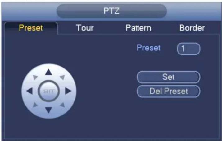
text_image
PTZ Preset Tour Pattern Border Preset 1 Set Del PresetFigure 4-22
Tour Setup
In Figure 4-21, click tour button.
Input tour value and preset No. Click Add preset button to add current preset to the tour. See Figure 4-23.
Tips
Repeat the above steps to add more presets to the tour. Click Del preset button to remove it from the tour. Please note some protocols do not support delete preset function.

text_image
PTZ Preset Tour Pattern Border Preset 1 Patrol No. 0 Add Preset Del Preset Del TourFigure 4-23
Pattern Setup
In Figure 4-21, click Pattern button and input pattern number.
Click Begin button to start direction operation. Or you can go back to Figure 4-18 to operate zoom/focus/iris/direction operation.
In Figure 4-21, click End button.
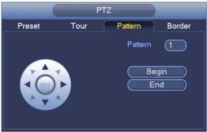
text_image
PTZ Preset Tour Pattern Border Pattern 1 Begin EndFigure 4-24
Scan Setup
In Figure 4-21, click Scan button.
Use direction buttons to set camera left limit and then click Left button.
Use direction buttons to set camera right limit and then click Right button. Now the scan setup process is complete.
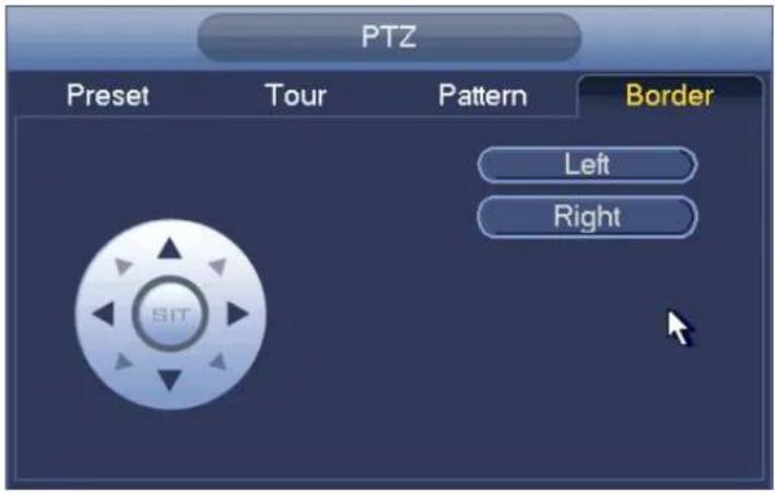
text_image
PTZ Preset Tour Pattern Border Left RightFigure 4-25
Call PTZ Function
Call Preset
In Figure 4-20, input preset value and then click 🙏 to call a preset. Click 🙏 again to stop call.
Call Pattern
In Figure 4-20, input pattern value and then click 📌 to call a pattern. Click 📌 again to stop call.
Call Tour
In Figure 4-20, input tour value and then click to call a tour. Click again to stop call.
Call Scan
In Figure 4-20, input Scan value and then click 📄 to call a tour. Click again 📄 to stop call.
Rotate
In Figure 4-20, click 📞 to enable the camera to rotate. System supports preset, tour, pattern, scan, rotate, light and etc function.
Note:
- Preset, tour and pattern all need the value to be the control parameters. You can define it as you require.
- You need to refer to your camera user's manual for Aux definition. In some cases, it can be used for special process.
Aux

Click, system goes to the following interface. The options here are defined by the protocol. The aux number is corresponding to the aux on-off button of the decoder. See Figure 4-26.
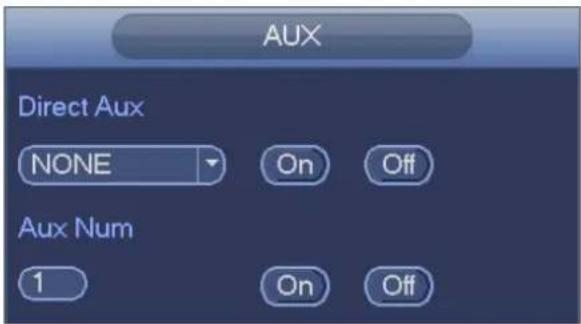
text_image
AUX Direct Aux NONE On Off Aux Num 1 On OffFigure 4-26
Color
Here you can set hue, brightness, contrast, saturation, gain, white level, color mode and etc. See Figure 4-27.
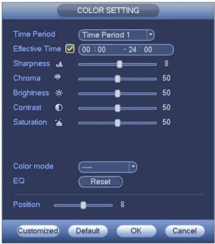
text_image
COLOR SETTING Time Period Time Period 1 Effective Time 00 : 00 - 24 : 00 Sharpness 8 Chroma 50 Brightness 50 Contrast 50 Saturation 50 Color mode ..... EQ Reset Position 8 Customized Default OK CancelFigure 4-27
Please refer to the following sheet for detailed information.
| Item | Note |
| Period | There are two periods in one day. You can set different sharpness, brightness, and contrast setup for different periods. |
| Effective Time | Check the box here to enable this function and then set period time. |
| Sharpness | The value here is to adjust the edge of the video. The value ranges from 0 to 100. The larger the value is, the clear the edge is and vice versa. Please note there is noise if the value here is too high. The default value is 50 and the recommendedvalue ranges from 40 to 60. |
| Brightness | It is to adjust monitor window bright. The value ranges from 0 to 100. The default value is 50.The larger the number, the bright the video is. When you input the value here, the bright section and the dark section of the video will be adjusted accordingly. You can use this function when the whole video is too dark or too bright. Please note the video may become hazy if the value is too high. The recommended value ranges from 40 to 60. |
| Contrast | It is to adjust monitor window contrast. The value ranges from 0 to 100. The default value is 50.The larger the number, the higher the contrast is. You can use this function when the whole video bright is OK but the contrast is not proper. Please note the video may become hazy if the value is too low. If this value is too high, the dark section may lack brightness while the bright section may over exposure .The recommended value ranges from 40 to 60. |
| Saturation | It is to adjust monitor window saturation. The value ranges from 0 to 100. The default value is 50.The larger the number, the strong the color is. This value has no effect on the general brightness of the whole video. The video color may become too strong if the value is too high. For the grey part of the video, the distortion may occur if the white balance is not accurate. Please note the video may not be attractive if the value is too low. The recommended value ranges from 40 to 60. |
| Color mode | It includes several modes such as standard, color, bright, gentle. Select a color mode, the sharpness, brightness, contrast and etc can automatically switch to corresponding setup. |
| EQ | Click reset button, device can automatically adjust to the best display effect. |
| Position | It is to adjust the image position on the screen. |
| Customized | Click it to set customized color mode. |
Display
It is to set display output mode. There are two modes: full screen (4:3)/image original rate (16:9). Icon

means current display output mode. See Figure 4-28.

text_image
View 1 View 4 View 9 View 16 Previous Screen Next Screen PTZ Auto Focus Color Setting Display Search Manual Remote Device Video Matrix Main Menu Full Screen Image Original RateFigure 4-28
Navigation Bar
You need to go to the Main menu->Setting->System->General to enable navigation bar function; otherwise you can not see the following interface.
The navigation bar is shown as below. See Figure 4-29.

text_image
1 2 3 4 5 6 7 8 9 10 11 12 13 14 15 16Figure 4-29
Main Menu
Click button to go to the main menu interface.
Output Screen
Select corresponding window-split mode and output channels.
Previse screen
Click it go to the previous screen.
Next Screen
Click it to go to the next screen.
Tour
Click button 🔒 to enable tour, the icon becomes 🔒, you can see the tour is in process.
Holis HD Series DVR User Manual 4, 8 & 16 Channel Models
Favorites
Click 🙏️, system pops up add/edit favorites.See Figure 4-30.

text_image
Add to Favorites Edit FavoritesFigure 4-30
Channel
It is to pop up channel tree. You can left click to select a channel on the tree and then drag it to the preview window on the left pane.
PTZ
Click , system goes to the PTZ control interface..
Color
Click button 📄, system goes to the color interface.
Search
Click button , system goes to search interface.
Alarm Status
Click button ⚠️, system goes to alarm status interface. It is to view device status and channel status.
Channel Info
Click button 📁, system goes to the channel information setup interface. It is to view information of the corresponding channel. See Figure 4-31.

text_image
CHANNEL INFO Channel Motion Video Loss Tampering Record Status Record Mode Resolution Frame Rate Bit Rate(0) 1 ● ● ● ● Regular 1280*720 25 56 2 ● ● ● ● Regular 1280*720 25 58 3 ● ● ● ● Regular 1280*720 25 58 4 ● ● ● ● Regular 1280*720 25 57 RefreshHolis HD Series DVR User Manual 4, 8 & 16 Channel Models
Figure 4-31
Remote Device
Click , system goes to an interface for you to view remote device information.
Network
Click 📄, system goes to the network interface. It is to set network IP address, default gateway and etc
HDD Manager
Click , system goes to the HDD manager interface. It is to view and manage HDD information.
USB Manager
Click 📋, system goes to the USB Manager interface. It is to view USB information, backup and update.
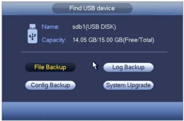
USB Device Auto Pop-up
After you inserted the USB device, system can auto detect it and pop up the following dialogue box. It allows you to conveniently backup file, log, configuration or update system. See Figure 4-32.
text_image
Find USB device Name: sdb1(USB DISK) Capacity: 14.05 GB/15.00 GB(Free/Total) File Backup Log Backup Config Backup System UpgradeFigure 4-32
Main Menu
The main menu interface is shown as below. See Figure 4-33.

text_image
MAIN MENU OPERATION SEARCH BACKUP SHUTDOWN INFO SYSTEM EVENT NETWORK LOG SETTING CAMERA NETWORK EVENT STORAGE SYSTEMFigure 4-33
Operation
Search
Click search button in the main menu, search interface is shown as below. See Figure 4-34. Usually there are three file types:
● R: Regular recording file.
● A: External alarm recording file.
● M: Motion detection recording file

text_image
2015-1-4 21:52:25 From R/W HDD REC PIC Splice Playback Sep 2013 Su Mo Tu We Th Fr Sa 1 2 3 4 5 6 7 8 9 10 11 12 13 14 15 16 17 18 19 20 21 22 23 24 25 26 27 28 29 30 CAM1 1 2 3 4 5 6 7 12 11 Stop Sync All Normal Alarm Motion 00:00:00 - 00:00:00 13Figure 4-34
Please refer to the following sheet for more information.
| SN | Name | Function | |
| 1 | Display window | ●Here is to display the searched picture or file.●Support 1/4/8-window playback. | |
| 2 | Search type | ●Here you can select to search the picture or the recorded file.●You can select to play from the read-write HDD, from peripheral device or from redundancy HDD.●Before you select to play from the peripheral device, please connect the corresponding peripheral device. You can view all record files of the root directory of the peripheral device. Click the Browse button; you can select the file you want to play.Important●Redundancy HDD does not support picture backup function, but it supports picture playback function. You can select to play from redundancy HDD if there are pictures on the redundancy HDD. | |
| 3 Calendar | ●The blue highlighted date means there is picture or file. Otherwise, there is no picture or file.●In any play mode, click the date you want to see, you can see the corresponding record file trace in the time bar. | ||
| 4 | Playback mode and channel selection pane. | ●Playback mode: 1/4/9. (It may vary due to different series.)✧ In 1-window playback mode: you can select 1-16 channels.✧ In 4-window playback mode: you can select 4 channels according to your requirement.✧ In 9-window playback mode, you can switch between 1-8 and 9-16 channels.✧ In customized mode, you can select one or more channel(s) you want to playback at the same time..●The time bar will change once you modify the playback mode or the channel | |
| option. | |||
| 5 | Card number search | The card number search interface is shown as below. Here you can view card number/field setup bar. You can implement advanced search. | |
| 6 | Mark file list button | Click it to go to mark file list interface. You can view all mark information of current channel by time. Please note only the product of this icon supports mark function. | |
| 7 | File list switch button | ●Double click it, you can view the picture/record file list of current day.●The file list is to display the first channel of the record file.●The system can display max 128 files in one time. Use the ◀|and |► or the mouse to view the file. Select one item, and then double click the mouse or click the ENTER button to playback.●You can input the period in the following interface to begin accurate search.●File type: R—regular record; A—external alarm record; M—Motion detect record. ●Lock file. Click the file you want to lock and click the button ●Lock file. Click the file you want to lock and click the button  to lock. The file you locked will not be overwritten.●Search locked file: Click the button to view the locked file. to lock. The file you locked will not be overwritten.●Search locked file: Click the button to view the locked file. system goes back to the calendar and channel setup interface.Please note:●For the file that is writing or overwriting, it can not be locked. system goes back to the calendar and channel setup interface.Please note:●For the file that is writing or overwriting, it can not be locked. | |
| 8 | Playback control pane. |  ►/IIThere are three ways for you to begin playback.● The play button● Double click the valid period of the time bar.● Double click the item in the file list.In slow play mode, click it to switch between play/pause. ►/IIThere are three ways for you to begin playback.● The play button● Double click the valid period of the time bar.● Double click the item in the file list.In slow play mode, click it to switch between play/pause. | |
| ■ | Stop | ||
| ◄ | Backward playIn normal play mode, left click the button, the file begins backward play.Click it again to pause current play.In backward play mode, click ►/II to restore normal play. | ||
| [BY3G] | In playback mode, click it to play the next or the previous section. You can click continuously when you are watching the files from the same channel.In normal play mode, when you pause current play, you can click ◀| and |► to begin frame by frame playback.In frame by frame playback mode, click ►/II to restore normal playback. | ||
| ► | Slow playIn playback mode, click it to realize various slow play modes such as slow play 1, slow play 2, and etc. | ||
| ► | Fast forwardIn playback mode, click to realize various fast play modes such as fast play 1,fast play 2 and etc. | ||
| Note: The actual play speed has relationship with the software version. | |||
 | Smart search | ||
 | The volume of the playback | ||
 | Click the snapshot button in the full-screen mode, the system can snapshot 1 picture.System supports custom snap picture saved path. Please connect the peripheral device first, click snap button on the full-screen mode, you can select or create path. Click Start button, the snapshot picture can be saved to the specified path. | ||
 | Mark button.Please note this function is for some series product only. Please make sure there is a mark button in the playback control pane. . | ||
| 9 Time bar | ●It is to display the record type and its period in current search criteria.●In 4-window playback mode, there are corresponding four time bars. In other playback mode, there is only one time bar.●Use the mouse to click one point of the color zone in the time bar, system begins playback.●The time bar is beginning with 0 o'clock when you are setting the configuration. The time bar zooms in the period of the current playback time when you are playing the file.●The green color stands for the regular record file. The red color stands for the external alarm record file. The yellow stands for the motion detect record file. | ||
| 10 | Time bar unit | ●The option includes: 24H, 12H, 1H and 30M. The smaller the unit, the larger the zoom rate. You can accurately set the time in the time bar to playback the record.●The time bar is beginning with 0 o'clock when you are setting the configuration. The time bar zooms in the period of the current playback time when you are playing the file. | |
| 11 Backup | ● Select the file(s) you want to backup from the file list. You can check from the list. Then click the backup button, now you can see the backup menu. System supports customized path setup. After select or create new folder, click the Start button to begin the backup operation. The record file(s) will be saved in the specified folder.● Check the file again you can cancel current selection. System max supports to display 32 files from one channel.● After you clip on record file, click Backup button you can save it.● For one device, if there is a backup in process, you can not start a new backup operation. | ||
| 12 Clip | ●It is to edit the file.●Please play the file you want to edit and then click this button when you want to edit. You can see the corresponding slide bars in the time bar of the corresponding channel. You can adjust the slide bar or input the accurate time to set the file end time.●After you set, you can click Clip button again to edit the second period. You can see the slide bar restore its previous position.●Click Backup button after clip, you can save current contents in a new file.●You can clip for one channel or multiple-channel. The multiple-channel click operation is similar with the one-channel operation.Please note:●System max supports 1024 files backup at the same time.●You can not operate clip operation if there is any file has been checked in the file list.● | ||
| 13 | Record type | In any play mode, the time bar will change once you modify the search type. | |
| Other Functions | ||
| 14 | Smart search | When system is playing, you can select a zone in the window to begin smart search. Click the motion detect button to begin play.Once the motion detect play has begun, click button again will terminate current motion detect file play.There is no motion detect zone by default.If you select to play other file in the file list, system switches to motion detect play of other file.During the motion detect play process, you can not implement operations such as change time bar, begin backward playback or frame by frame playback. |
| 15 | Other channel synchronization switch to play when playback | When playing the file, click the number button, system can switch to the same period of the corresponding channel to play. |
| 16 | Digital zoom | When the system is in full-screen playback mode, left click the mouse in the screen. Drag your mouse in the screen to select a section and then left click mouse to realize digital zoom. You can right click mouse to exit. |
| 17 | Manually switch channel when playback | During the file playback process, you can switch to other channel via the dropdown list or rolling the mouse.This function is null if there is no record file or system is in smart search process. |
Smart Search
During the multiple-channel playback mode, double click one channel and then click the button, system begins smart search. System supports 396(22*18 PAL) and 330(22*15 NTSC) zones. Please left click mouse to select smart search zones. See Figure 4-35.

text_image
From RW HDD RECORD PIC Splice Playback Jan 2016 Su Mo Tu We Th Sa 3 4 5 6 7 8 9 10 11 12 13 14 15 16 17 18 19 20 21 22 23 24 25 26 27 28 29 30 21 1 2 2 4 Play Sync All Normal Alarm Motion 00:00:00 - 00:00:00Figure 4-35
Click the 📁, you can go to the smart search playback. Click it again, system stops smart search playback.
Important
- System does not support motion detect zone setup during the full-screen mode.
- During the multiple-channel playback, system stops playback of rest channels if you implement one-channel smart search.
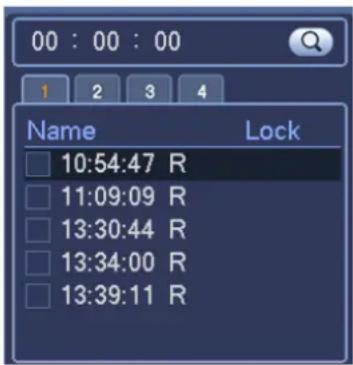
Accurate playback by time
Select records from one day, click the list, you can go to the file list interface. You can input time at the top right corner to search records by time. See image on the left side of the Figure 4-36 For example,
input time 11:00.00 and then click Search button 📄, you can view all the record files after 11:00.00 (The records includes current time.). See image on the right side of the Figure 4-36 Double click a file name to playback.
Note
- After you searched files, system implement accurate playback once you click Play for the first time.
● System does not support accurate playback for picture. - System supports synchronization playback and non-synchronous playback. The synchronization playback supports all channels and non-synchronous playback only supports accurately playback of current select channel.
text_image
00 : 00 : 00 1 2 3 4 Name Lock 10:54:47 R 11:09:09 R 13:30:44 R 13:34:00 R 13:39:11 R
text_image
11 : 09 : 00 1 2 3 4 Name Lock 11:09:09 R 13:30:44 R 13:34:00 R 13:39:11 R 15:00:00 RFigure 4-36
Mark Playback
Please make sure your purchased device support this function. You can use this function only if you can see the mark playback icon on the Search interface (Figure 4-34).
When you are playback record, you can mark the record when there is important information. After playback, you can use time or the mark key words to search corresponding record and then play. It is very easy for you to get the important video information.
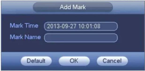
- Add Mark
Holis HD Series DVR User Manual 4, 8 & 16 Channel Models
When system is playback, click Mark button ⚙️, you can go to the following interface. See Figure 4-37.
text_image
Add Mark Mark Time 2013-09-27 10:01:08 Mark Name Default OK CancelFigure 4-37
- Playback Mark
During 1-window playback mode, click mark file list button in Figure 4-34, you can go to mark file list interface. Double click one mark file, you can begin playback from the mark time.
- Play before mark time
Here you can set to begin playback from previous N seconds of the mark time.
Note
Usually, system can playbacks previous N seconds record if there is such kind of record file. Otherwise, system playbacks from the previous X seconds when there is such as kind of record.
- Mark Manager
Click the mark manager button 📄 on the Search interface (Figure 4-34); you can go to Mark Manager interface. See Figure 4-38. System can manage all the record mark information of current channel by default. You can view all mark information of current channel by time.

text_image
Marks Manager Channel 1 Start Time 2013 - 09 - 27 00 : 00 : 00 End Time 2013 - 09 - 28 00 : 00 : 00 Search 1 CH Mark Time Mark Name 1 1 2013-09-27 10:00:12 report Delete ExitFigure 4-38
- Modify
Double click one mark information item, you can see system pops up a dialogue box for you to change mark information. You can only change mark name here.
- Delete
Here you can check the mark information item you want to delete and then click Delete button, you can remove one mark item.
Note
- After you go to the mark management interface, system needs to pause current playback. System resume playback after you exit mark management interface.
- If the mark file you want to playback has been removed, system begin playback from the first file in the list.
Customized Playback
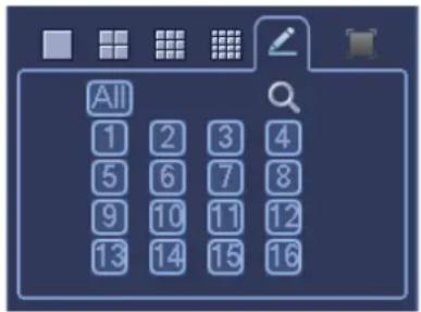
You can select one or more channel(s) to playback at the same time.
From main menu->Search or you can right click mouse on the preview interface and then select Search, you can go to Figure 4-34.
In pane 4, click 📄, you can see the following interface. See Figure 4-39.
text_image
All 1 2 3 4 5 6 7 8 9 10 11 12 13 14 15 16Figure 4-39
Now you can select one or more channel(s) and then click 🔒 to search record(s).
System supports one or more channels. The window split mode can auto adjust according to the channel amount. System max supports 16-split.

Click ▶, system begins playback.
Splice Playback
For the large record file, you can use splice playback function to play the same file in several sections at the same time. It is very convenient for you to find the video footages you desire.
On the main menu, click Search button, or right click mouse and then select Search. You can go to the Figure 4-34.
On the right pane, check the box to enable splice playback function, and then set channel, date, split mode. The splice playback interface is shown as below. Each section has a small triangle; you can
adjust it to set time. See Figure 4-40.

bar
| Position | Value | |---|---| | 1 | 0.05 | | 2 | 0.10 | | 3 | 0.15 | | 4 | 0.20 | | 5 | 0.25 | | 6 | 0.30 | | 7 | 0.35 | | 8 | 0.40 | | 9 | 0.45 | | 10 | 0.50 | | 11 | 0.55 | | 12 | 1.00 |Figure 4-40
Note
Select split mode, so that the record can be spliced in several sections.
Select splice file.
- Click Playback, system playbacks from the first of current date by default.
- Click time bar, system playbacks from the time you click.
- Click , you can select on the file list.
Note
● The splice playback is for 1-window playback mode.
● System supports 1/4/8/16-split mode. Slight different may be found here.
- The min period of each section is 5 minutes. For the record is less than 20 minutes, if you select 4-split mode (or more than 4-split mode), system can auto adjust so that the each section period is 5 minutes. In this situation, some channel may have no video.
Backup
DVR support CD-RW, DVD burner, USB device backup, network download and eSATA. Here we introduce USB, eSATA backup. Operation for network download backup operation.
Click backup button, you can see an interface is shown as in Figure 4-41. Here is for you to view devices information.
You can view backup device name and its total space and free space. The device includes CD-RW, DVD burner, USB device, flash disk, eSATA backup.
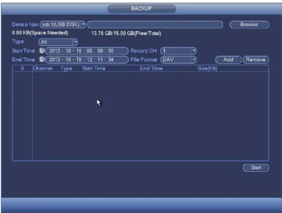
text_image
BACKUP Device Nan sdc1(USB DISK) Browse 0.00 KB(Space Needed) 13.78 GB/15.00 GB(Free/Total) Type All Start Time 2013 - 10 - 18 00 : 00 : 00 Record CH 1 End Time 2013 - 10 - 18 12 : 11 : 34 File Format DAV Add Remove 0 Channel Type Start Time End Time Size(KB) StartFigure 4-41
Select backup device and then set channel, file start time and end time.
Click add button, system begins search. All matched files are listed below. System automatically calculates the capacity needed and remained. See Figure 4-43.

text_image
BACKUP Device Nan sdc1(USB DISK) Browse 1.26 GB(Space Needed) 13.78 GB/15.00 GB(Free/Total) Type All Start Time 2013 - 10 - 10 00 : 00 : 00 Record CH 1 End Time 2013 - 10 - 18 12 : 11 : 34 File Format DAV Add Remove 43 Channel Type Start Time End Time Size(KB) 1 ✓ 1 R 13-10-14 22:00:00 13-10-14 23:00:00 48176 2 ✓ 1 R 13-10-14 23:00:00 13-10-15 00:00:00 48037 3 ✓ 1 R 13-10-15 00:00:00 13-10-15 00:28:50 22528 4 ✓ 1 R 13-10-15 00:28:50 13-10-15 01:00:00 24668 5 ✓ 1 R 13-10-15 01:00:00 13-10-15 02:00:00 46815 6 ✓ 1 R 13-10-15 02:00:00 13-10-15 03:00:00 47802 7 ✓ 1 R 13-10-15 03:00:00 13-10-15 04:00:00 47566 8 ✓ 1 R 13-10-15 04:00:00 13-10-15 05:00:00 47468 9 ✓ 1 R 13-10-15 05:00:00 13-10-15 06:00:00 47358 10 ✓ 1 R 13-10-15 06:00:00 13-10-15 07:00:00 47773 11 ✓ 1 R 13-10-15 07:00:00 13-10-15 08:00:00 47229 12 ✓ 1 R 13-10-15 08:00:00 13-10-15 09:00:00 47865 13 ✓ 1 R 13-10-15 09:00:00 13-10-15 09:32:27 2789 StartFigure 4-42
System only backup files with a √ before channel name. You can use Fn or cancel button to delete √ after file serial number.
Click Start button, system begins copy. At the same time, the backup button becomes stop button. You can view the remaining time and process bar at the left bottom. See Figure 4-43.

text_image
BACKUP Device Nan sdc1(USB DISK) Browse 139.88 MB(Space Needed) 13.78 GB/15.00 GB(Free/Total) Type All Start Time 2013 - 10 - 10 00 : 00 : 00 Record CH 1 End Time 2013 - 10 - 18 12 : 11 : 34 File Format DAV Add Remove 43 Channel Type Start Time End Time Size(KB) 1 1 R 13-10-14 22:00:00 13-10-14 23:00:00 48176 2 ✓ 1 R 13-10-14 23:00:00 13-10-15 00:00:00 48037 3 ✓ 1 R 13-10-15 00:00:00 13-10-15 00:28:50 22628 4 ✓ 1 R 13-10-15 00:28:50 13-10-15 01:00:00 24668 5 ✓ 1 R 13-10-15 01:00:00 13-10-15 02:00:00 46815 6 1 R 13-10-15 02:00:00 13-10-15 03:00:00 47802 7 1 R 13-10-15 03:00:00 13-10-15 04:00:00 47566 8 1 R 13-10-15 04:00:00 13-10-15 05:00:00 47468 9 1 R 13-10-15 05:00:00 13-10-15 06:00:00 47358 10 1 R 13-10-15 06:00:00 13-10-15 07:00:00 47773 11 1 R 13-10-15 07:00:00 13-10-15 08:00:00 47229 12 1 R 13-10-15 08:00:00 13-10-15 09:00:00 47865 13 1 R 13-10-15 09:00:00 13-10-15 09:32:22 2780 14 1 R 13-10-15 09:55:55 13-10-15 09:57:22 49869 Stop Remaining time 0:2:59Figure 4-43
When the system completes backup, you can see a dialogue box prompting successful backup.
- File format: Click the file format; you can see there are two options: DAV/ASF.
The file name format usually is: Channel number+Record type+Time. In the file name, the YDM format is Y+M+D+H+M+S. File extension name is .dav.
Tips:
During backup process, you can click ESC to exit current interface for other operation. The system will not terminate backup process.
Note:
When you click stop button during the burning process, the stop function becomes activated immediately. For example, if there are ten files, when you click stop system just backup five files, system only save the previous 5 files in the device (But you can view ten file names).
Shut Down
In Figure 4-33, select Shut Down, you can go to the following interface. See Figure 4-44.
There are three options: Shutdown/logout/reboot. See Figure 4-44.
For the user who does not have the shut down right, please input corresponding password to shut down.
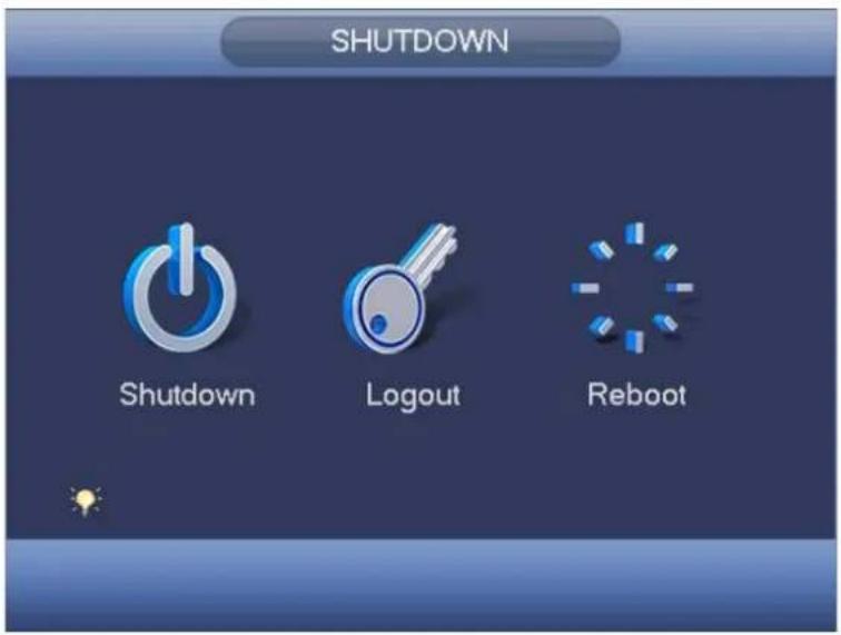
text_image
SHUTDOWN Shutdown Logout RebootFigure 4-44
Information
It is for you to view system info, event info, and network info and log info.
System Info
Here is for you to view system information. There are total four items: HDD (hard disk information), record, BPS (data stream statistics), version. See Figure 4-45.

text_image
INFO SYSTEM EVENT NETWORK LOG HDD RECORD REC ESTIMATE BPS CHANNEL INFO VERSION SATA 1 0 1° Type Total Space Free Space Status S.M.A.R.T All - 1.81 TB 1.64 TB - - 1° Read/Write 1.81 TB 1.64 TB NormalFigure 4-45
HDD Information
Here is to list hard disk type, total space, free space, video start time and status. See Figure 4-46.
- SATA: 1 here means system max supports 1 HDD. ○ means current HDD is normal. X means there is error. - means there is no HDD. If disk is damaged, system shows as “?”. Please remove the broken hard disk before you add a new one.
- SN: You can view the HDD amount the device connected to. * means the second HDD is current working HDD.
● Type: The corresponding HDD properties.
● Total space: The HDD total capacity.
● Free space: The HDD free capacity.
● Status: HDD can work properly or not.
● SMART: Display HDD information. See Figure 4-46.
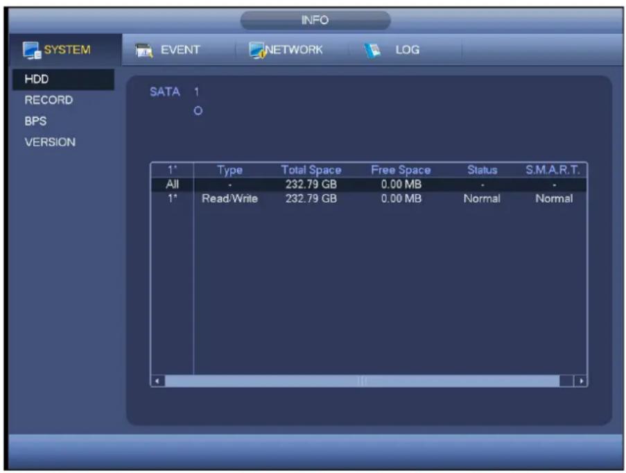
text_image
INFO SYSTEM EVENT NETWORK LOG HDD RECORD BPS VERSION SATA 1 1* Type Total Space Free Space Status S.M.A.R.T. All - 232.79 GB 0.00 MB - - 1* Read/Write 232.79 GB 0.00 MB Normal NormalFigure 4-46
Double click one HDD information; you can see the HDD SMART information. See Figure 4-47.

text_image
S.M.A.R.T INFO Port 1 Modle ST2000VX000-1CU164 No. Z1E4TXG4 Status OK Describe: Smart ID Attribute Threshold Value Worst Value Status 1 Read Error Rate 6 116 91 OK 3 Spin Up Time 0 97 95 OK 4 Start/Stop Count 20 100 100 OK 5 Reallocated Sector Count 10 100 100 OK 7 Seek Error Rate 30 72 60 OK 9 Power On Hours Count 0 93 93 OK 10 Spin-up Retry Count 97 100 100 OK 12 Power On/Off Count 20 100 100 OK 184 End-to-End Error 99 100 100 OK 187 Reported Uncorrect 0 86 86 OK 188 Command Timeout 0 100 99 OK 189 High Fly Writes 0 1 1 OK 191 G-Sense Error Rate 0 100 100 OK 192 Power-Off Retract Cycle 0 100 100 OK 193 Load/Unload Cycle Count 0 100 100 OK 194 Temperature 0 27 65 OKFigure 4-47
Record Info
It is to view record start time and end time. See Figure 4-48.
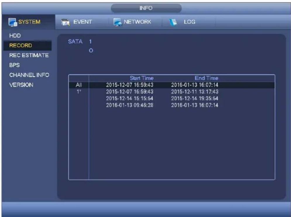
text_image
INFO SYSTEM EVENT NETWORK LOG HDD RECORD REC ESTIMATE BPS CHANNEL INFO VERSION SATA 1 O Start Time End Time All 2015-12-07 16:59:43 2016-01-13 16:07:14 1° 2015-12-07 16:59:43 2015-12-11 13:17:43 2015-12-14 15:15:54 2015-12-14 19:35:54 2016-01-13 09:46:28 2016-01-13 16:07:14Figure 4-48
Record Estimate
System can calculate the record time based on the HDD space, or you can input the record time you want to calculate the HDD space you need. See Figure 2-2.
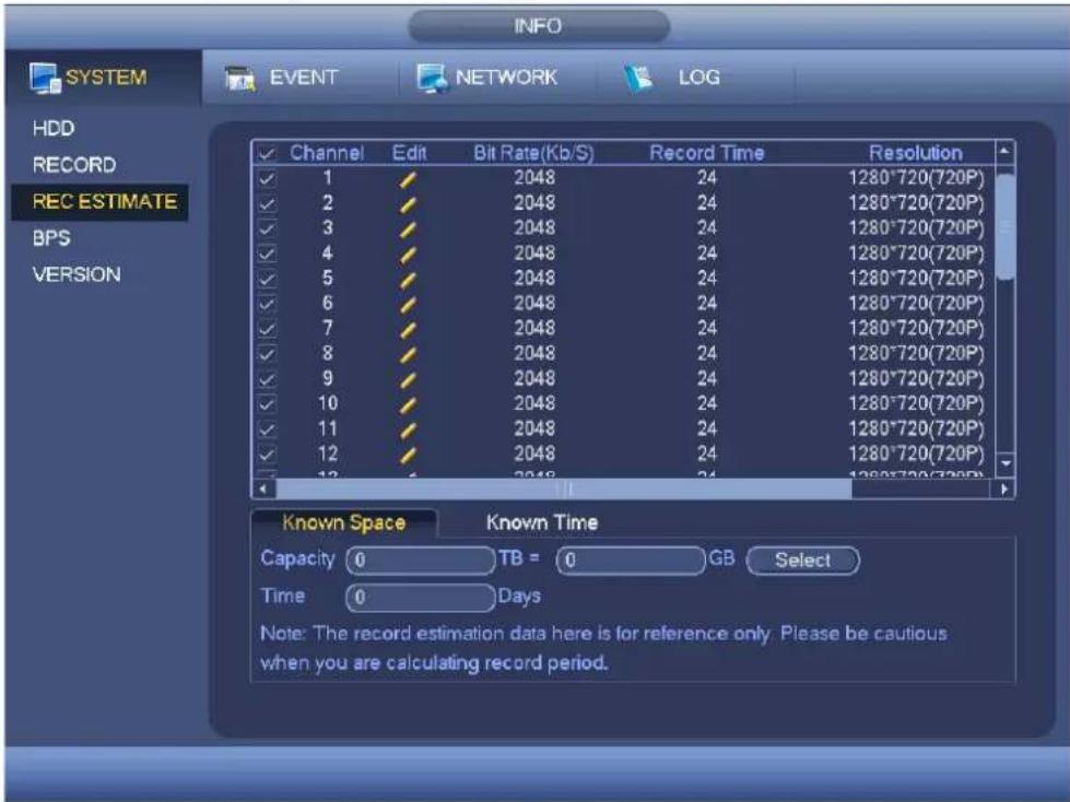
text_image
INFO SYSTEM EVENT NETWORK LOG HDD RECORD REC ESTIMATE BPS VERSION ✓ Channel Edit Bit Rate(Kb/S) Record Time Resolution ✓ 1 ✓ 2048 24 1280*720(720P) ✓ 2 ✓ 2048 24 1280*720(720P) ✓ 3 ✓ 2048 24 1280*720(720P) ✓ 4 ✓ 2048 24 1280*720(720P) ✓ 5 ✓ 2048 24 1280*720(720P) ✓ 6 ✓ 2048 24 1280*720(720P) ✓ 7 ✓ 2048 24 1280*720(720P) ✓ 8 ✓ 2048 24 1280*720(720P) ✓ 9 ✓ 2048 24 1280*720(720P) ✓ 10 ✓ 2048 24 1280*720(720P) ✓ 11 ✓ 2048 24 1280*720(720P) ✓ 12 ✓ 2048 24 1280*720(720P) ✓ 13 ✓ 2048 24 1280*720(720P) Known Space Known Time Capacity TB = GB Select Time Days Note: The record estimation data here is for reference only. Please be cautious when you are calculating record period.Figure 4-49
Click after the channel name, system pops up Edit dialogue box.. You can input resolution, frame rate, bit stream, record time of the corresponding channel, system can calculate the record time based on the channel setup and HDD space.
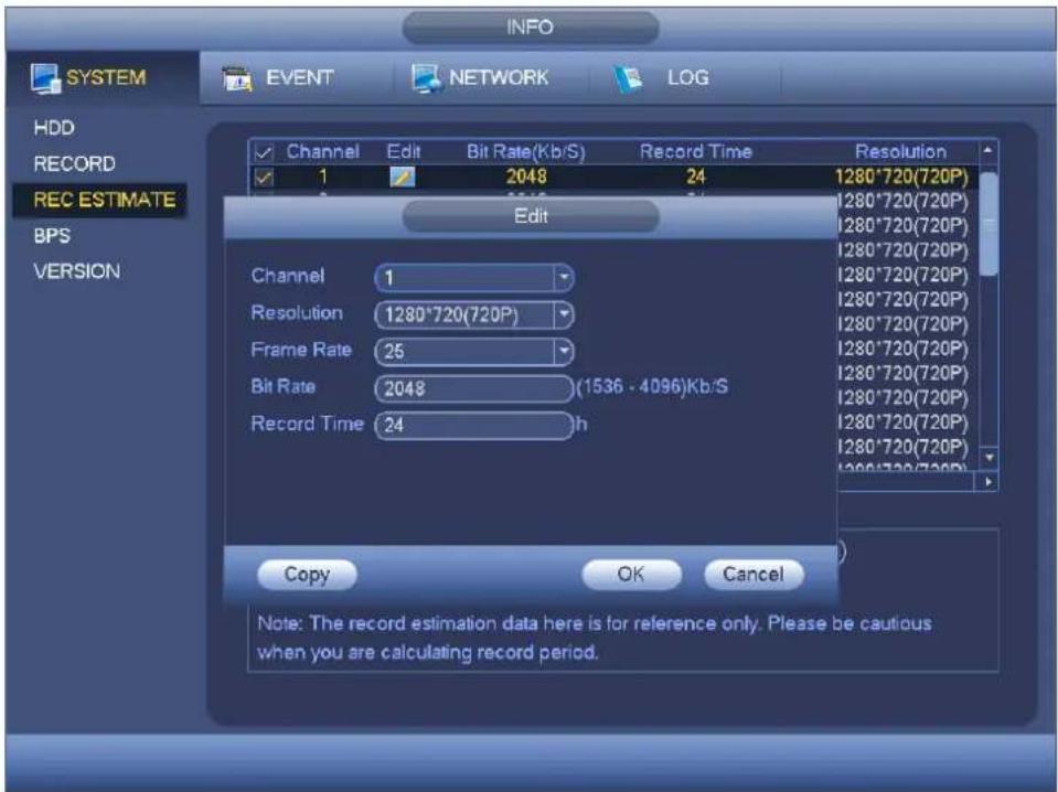
text_image
INFO SYSTEM EVENT NETWORK LOG HDD RECORD REC ESTIMATE BPS VERSION Channel Edit Bit Rate(Kb/S) Record Time Resolution 1 2048 24 1280*720(720P) Edit Channel 1 Resolution 1280*720(720P) Frame Rate 25 Bit Rate 2048 (1536 - 4096)Kb/S Record Time 24 h Copy OK Cancel Note: The record estimation data here is for reference only. Please be cautious when you are calculating record period.Figure 4-50
Holis HD Series DVR User Manual 4, 8 & 16 Channel Models
● Calculate the record period based on the HDD space
Check the channel you want to record file.

Click Known Space and then click the
button to set HDD. Click OK button.
Now you can see the record period (such as 5 days).

text_image
INFO SYSTEM EVENT NETWORK LOG HDD RECORD REC ESTIMATE BPS VERSION ✓ Channel Edit Bit Rate(Kb/S) Record Time Resolution ✓ 1 ✓ 2048 24 1280*720(720P) ✓ 2 ✓ 2048 24 1280*720(720P) ✓ 3 ✓ 2048 24 1280*720(720P) ✓ 4 ✓ 2048 24 1280*720(720P) ✓ 5 ✓ 2048 24 1280*720(720P) ✓ 6 ✓ 2048 24 1280*720(720P) ✓ 7 ✓ 2048 24 1280*720(720P) ✓ 8 ✓ 2048 24 1280*720(720P) ✓ 9 ✓ 2048 24 1280*720(720P) ✓ 10 ✓ 2048 24 1280*720(720P) ✓ 11 ✓ 2048 24 1280*720(720P) ✓ 12 ✓ 2048 24 1280*720(720P) 13 ✓ 2048 24 1280*720(720P) Known Space Known Time Capacity 4.000 TB = 4000 GB Select Time 5 Days Note: The record estimation data here is for reference only. Please be cautious when you are calculating record period.Figure 4-51
● Calculate the HDD space based on the record period
Check the channel you want to record file.
Input days(s) you want to records, system can auto calculate the HDD space needed (such as 5.109TB). See Figure 4-52.
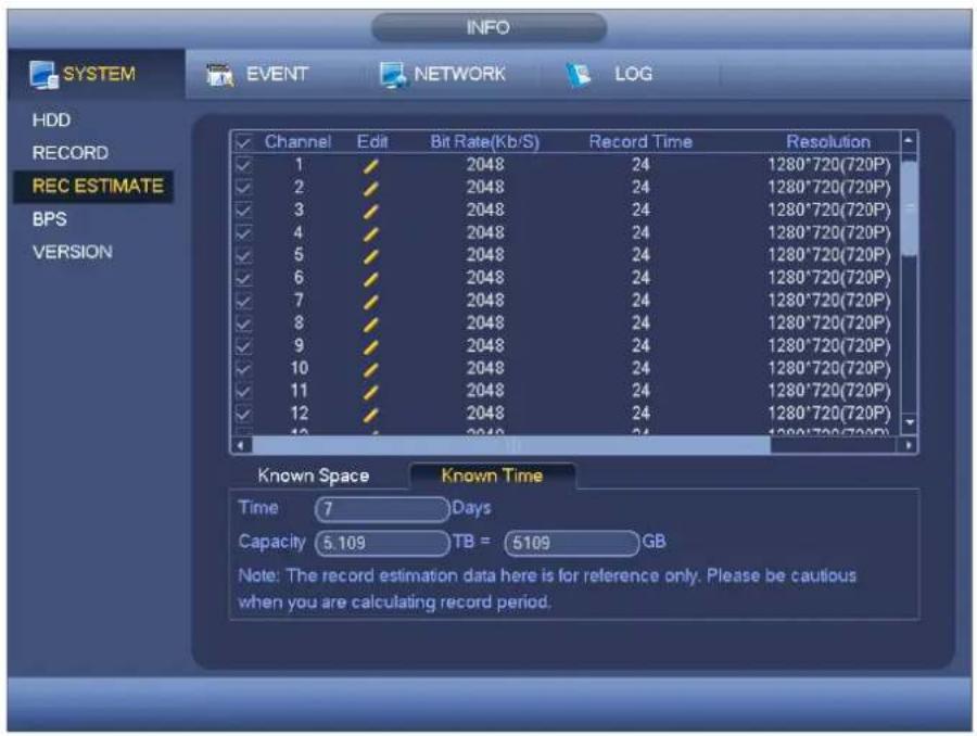
text_image
INFO SYSTEM EVENT NETWORK LOG HDD RECORD REC ESTIMATE BPS VERSION ✓ Channel Edit Bit Rate(Kb/S) Record Time Resolution ✓ 1 ✓ 2048 24 1280*720(720P) ✓ 2 ✓ 2048 24 1280*720(720P) ✓ 3 ✓ 2048 24 1280*720(720P) ✓ 4 ✓ 2048 24 1280*720(720P) ✓ 5 ✓ 2048 24 1280*720(720P) ✓ 6 ✓ 2048 24 1280*720(720P) ✓ 7 ✓ 2048 24 1280*720(720P) ✓ 8 ✓ 2048 24 1280*720(720P) ✓ 9 ✓ 2048 24 1280*720(720P) ✓ 10 ✓ 2048 24 1280*720(720P) ✓ 11 ✓ 2048 24 1280*720(720P) ✓ 12 ✓ 2048 24 1280*720(720P) ✓ 13 ✓ 2048 24 1280*720(720P) Known Space Known Time Time 7 Days Capacity 5.109 TB = 5109 GB Note: The record estimation data here is for reference only. Please be cautious when you are calculating record period.Figure 4-52
BPS
Here is for you to view current video data stream (KB/s), resolution and etc. See Figure 4-53.
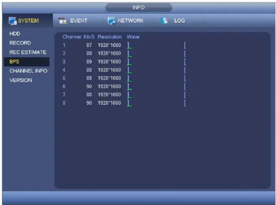
text_image
INFO SYSTEM EVENT NETWORK LOG HDD RECORD REC ESTIMATE BPS CHANNEL INFO VERSION Channel Kb/S Resolution Wave 1 87 1920°1080 ] 2 89 1920°1080 [] 3 89 1920°1080 [] 4 88 1920°1080 [] 5 88 1920°1080 [] 6 90 1920°1080 [] 7 88 1920°1080 [] 8 90 1920°1080 []Figure 4-53
Version
Holis HD Series DVR User Manual 4, 8 & 16 Channel Models
Here is for you to view some version information such as version number, built date, serial number and etc. See Figure 4-54.
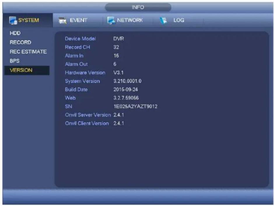
text_image
INFO SYSTEM EVENT NETWORK(LOG HDD RECORD REC ESTIMATE BPS VERSION Device Model DVR Record CH 32 Alarm In 16 Alarm Out 6 Hardware Version V3.1 System Version 3.210.0001.0 Build Date 2015-09-24 Web 3.2.7.59066 SN 1E025A2YAZT9012 Onvil Server Version 2.4.1 Onvil Client Version 2.4.1Figure 4-54
Event
It is to display device status and channel status. See Figure 4-55.
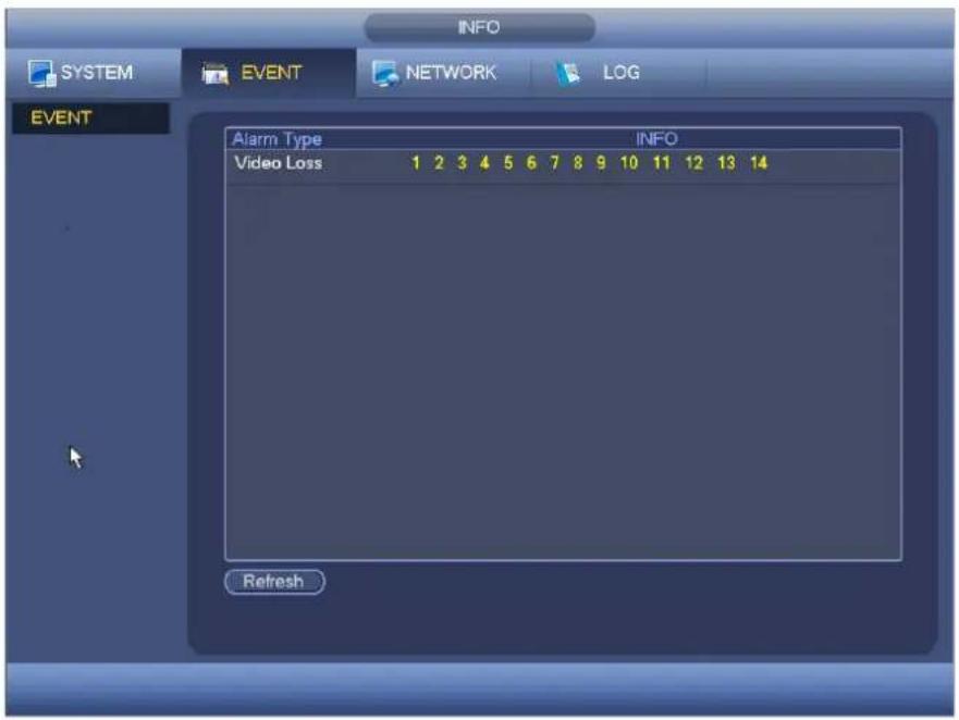
text_image
INFO SYSTEM EVENT NETWORK LOG EVENT Alarm Type INFO Video Loss 1 2 3 4 5 6 7 8 9 10 11 12 13 14 RefreshFigure 4-55
Network
Holis HD Series DVR User Manual 4, 8 & 16 Channel Models
Online Users
Here is for you to manage online users. See Figure 4-56.
You can disconnect one user or block one user if you have proper system right. Max disconnection setup is 65535 seconds.
System detects there is any newly added or deleted user in each five seconds and refresh the list automatically.
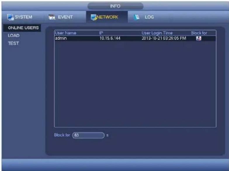
text_image
INFO SYSTEM EVENT NETWORK(LOG ONLINE USERS LOAD TEST User Name IP User Login Time Block for admin 10.15.6.144 2013-10-21 03:28:05 PM Block for 60 sFigure 4-56
Network Load
Network load is shown as in Figure 4-57. Here you can view the follow statistics of the device network adapter.
Here you can view information of all connected network adapters. The connection status is shown as offline if connection is disconnected. Click one network adapter, you can view the flow statistics such as send rate and receive rate at the top panel.

text_image
INFO SYSTEM EVENT NETWORK(LOG ONLINE USERS LOAD TEST Name MAC ADDRESS Status IP Address Type MTU LAN1 90:02:a9:ba:37:38 Succeed 10.18.116.190 Ethernet 1500 256 Kb/S 0 LAN1 Send Speed 0 Kb/S P receive Speed 29 Kb/SFigure 4-57
Network Test
Network test interface is shown as in Figure 4-58.
- Destination IP: Please input valid IPV4 address or domain name.
- Test: Click it to test the connection with the destination IP address. The test results can display average delay and pac ket loss rate and y ou can also view the network status as OK, bad, no connection and etc.
- Network Sniffer backup: Please insert USB2.0 device and click the Refresh button, you can view the device on the following column. You can use the dropdown list to select peripheral device. Click Browse button to select the snap path. The steps here are same as preview backup operation.
You can view all connected network adapter names (including Ethernet, PPPoE, WIFI, and 3G), you can click the button 📋 on the right panel to begin Sniffer. Click the grey stop button to stop. Please note system can not Sniffer several network adapters at the same time.
After Sniffer began, you can exit to implement corresponding network operation such as login WEB, monitor. Please go back to Sniffer interface to click stop Sniffer. System can save the packets to the specified path. The file is named after "Network adapter name+time". You can use software such as Wireshark to open the packets on the PC for the professional engineer to solve complicated problems.

text_image
INFO SYSTEM EVENT NETWORK(LOG ONLINE USERS LOAD TEST Network Test Destination IP Test Test Result Network Sniffer Packet Backup Device Name sdc1(USB DISK) Refresh Address / Browse Name IP Sniffer Packet Size Sniffer Packet Backup LAN1 10.15.6.145 0KBFigure 4-58
Log
Here is for you to view system log file. System lists the following information. See Figure 4-59. Log types include system operation, configuration operation, data management, alarm event, record operation, account manager, log clear, file operation and etc. It optimized reboot log. There are only three types: normal reboot, abnormal reboot and protection reboot. 0x02、0x03、0x04 is included in the protection reboot type.
- Start time/end time: Pleased select start time and end time, then click search button. You can view the log files in a list. System max displays 100 logs in one page. It can max save 1024 log files. Please use page up/down button on the interface or the front panel to view more.
- Backup: Please select a folder you want to save; you can click the backup button to save the log files. After the backup, you can see there is a folder named Log_time on the backup path. Double click the folder, you can see the log file
● Details: Click the Details button or double click the log item, you can view the detailed information. See Figure 4-60. Here you can use rolling bar to view information, or you can use Page up/Page down to view other log information.
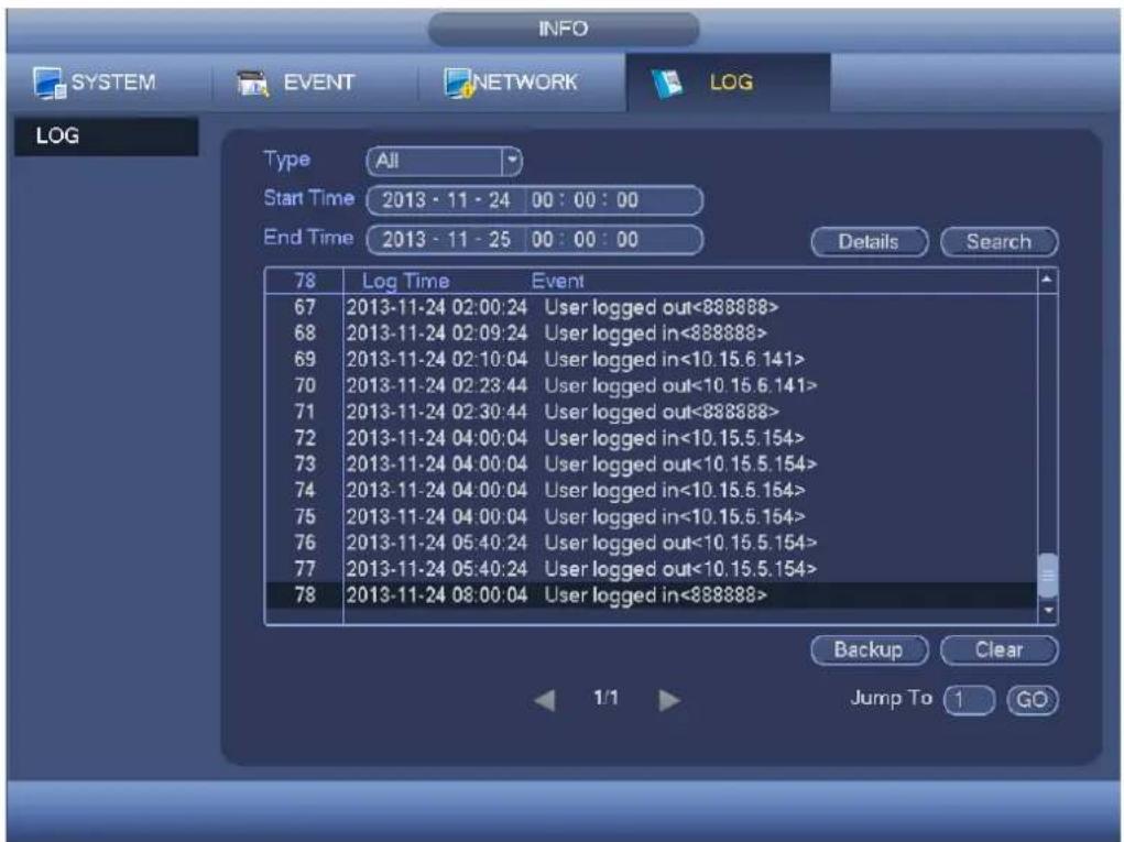
text_image
INFO SYSTEM EVENT NETWORK(LOG LOG Type All Start Time 2013 - 11 - 24 00 : 00 : 00 End Time 2013 - 11 - 25 00 : 00 : 00 Details Search 78 Log Time Event 67 2013-11-24 02:00:24 User logged out<888888> 68 2013-11-24 02:09:24 User logged in<888888> 69 2013-11-24 02:10:04 User logged in<10.15.6.141> 70 2013-11-24 02:23:44 User logged out<10.15.6.141> 71 2013-11-24 02:30:44 User logged out<888888> 72 2013-11-24 04:00:04 User logged in<10.15.5.154> 73 2013-11-24 04:00:04 User logged out<10.15.5.154> 74 2013-11-24 04:00:04 User logged in<10.15.5.154> 75 2013-11-24 04:00:04 User logged in<10.15.5.154> 76 2013-11-24 05:40:24 User logged out<10.15.5.154> 77 2013-11-24 05:40:24 User logged out<10.15.5.154> 78 2013-11-24 08:00:04 User logged in<888888> Backup Clear Jump To GOFigure 4-59
Select an item on the list and then click the Details button or double click the log item, you can view the detailed information such as log time, log type, log user, IP address and etc. See Figure 4-60.
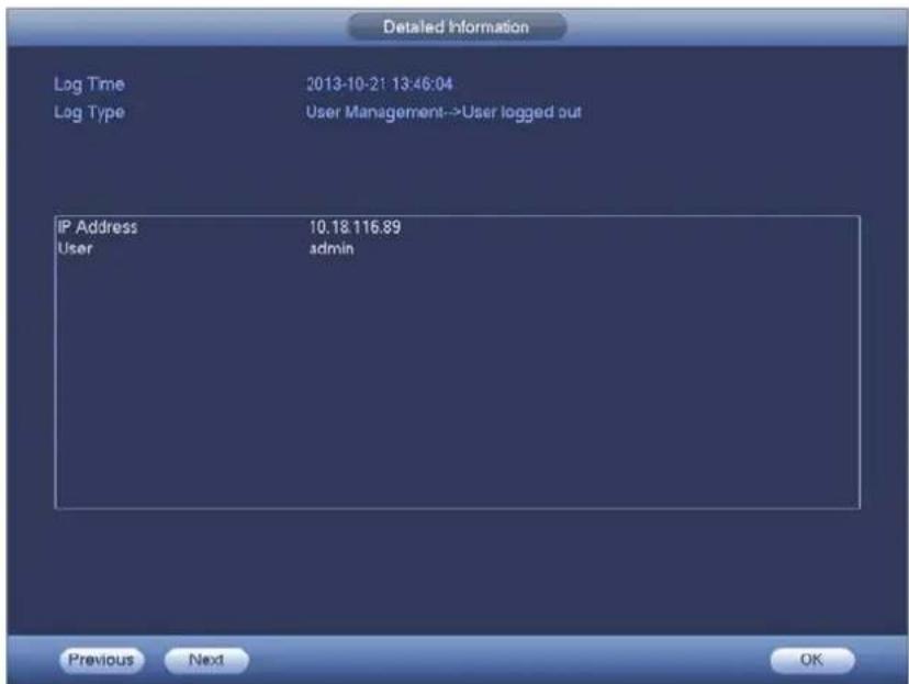
text_image
Detailed Information Log Time 2013-10-21 13:46:04 Log Type User Management-->User logged out IP Address 10.18.116.89 User adults Previous Next OKFigure 4-60
Setting
It is for you to set camera, network, event, storage, system and etc.
Camera
Here you can set audio/video property, camera property and channel name, channel type.
Remote Device (For digital channel only)
Note
You can see this interface after you set IP channel. System supports ONVIF standard protocol.
Remote Device
In the main menu, from Camera ->Remote, you can go to an interface shown as in Figure 4-61. Here you can add/delete remote device and view its corresponding information.
- IP search: Click it to search IP address. It includes device IP address, port, device name, manufacturer, type. Use your mouse to click the item name, you can refresh display order. Click IP address, system displays IP address from small to large. Click IP address again, you can see icon, system displays IP address from large to small. You can click other items to view information conveniently. For the network device already added to the device, you can see there is a small icon “*” after the SN in case there is repeatedly add operation.
- Add: Click it to connect to the selected device and add it to the Added device list. Support Batch add.
You can see the corresponding dialogue box if all digital-channel has connected to the front-end.
System can not add new device if the device you want to add has the same IP and TCP port as the device in the list.
● Show filter: You can use it to display the specified devices from the added device.
- Edit: Click button or double click a device in the list, you can change channel setup.
- Delete: Please select one device in the Added device list and then click ✗ to remove.
- Status: means connection is OK and means connection failed.
- Delete: Select a device on the Added device list, click Delete button, system disconnect device first and then remove its name from the list.
- Manual add: Click it to add the IPC manually. The port number is 37777. The default user name is admin and password is admin.
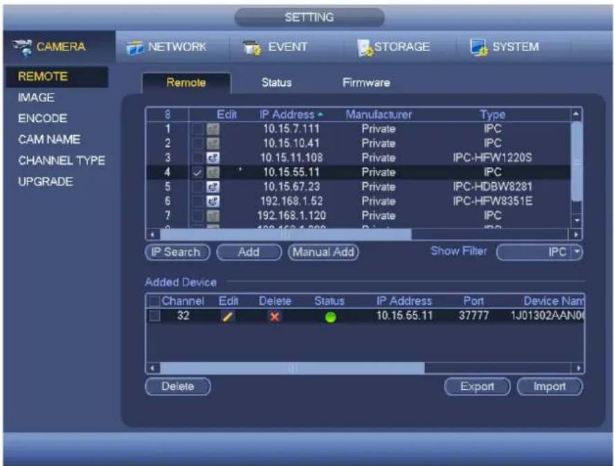
text_image
CAMERA NETWORK EVENT STORAGE SYSTEM REMOTE Remote Status Firmware 8 Edit IP Address Manufacturer Type 1 10.15.7.111 Private IPC 2 10.15.10.41 Private IPC 3 10.15.11.108 Private IPC-HFW1220S 4 10.15.55.11 Private IPC 5 10.15.67.23 Private IPC-HDBW8281 6 192.168.1.52 Private IPC-HFW8351E 7 192.168.1.120 Private IPC 8 100.168.1.200 Private IPC IP Search Add Manual Add Show Filter IPC Added Device Channel Edit Delete Status IP Address Port Device Nam 32 10.15.55.11 37777 1J01302AAN04 Delete Export ImportFigure 4-61
Click the Manual Add button; you can go to the following interface. See Figure 4-62.
Channel number: The dropdown list here displays unconnected channel number. You can go to Figure 4-61 to set remote channel connection.
Note:
- This series product supports the IPC from many popular manufactures such as Sony, Hitachi, Axis, Samsung, Dynacolor, Arecont, Onvif and Dahua.
- System default IP address is 192.168.0.0 if you do not input IP address. System will not add current IP address.
- You can not add two or more devices in the Manual Add interface (Figure 4-62). Click OK button, system connects to the corresponding front-end device of current channel on the interface.
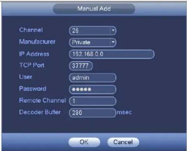
text_image
Manual Add Channel 25 Manufacturer Private IP Address 192.168.0.0 TCP Port 37777 User admin Password •••••• Remote Channel 1 Decoder Butler 280 lmsec OK CancelFigure 4-62
● Show filer: It is to filter the searched device.
■ None: it is to display all searched devices.
Holis HD Series DVR User Manual 4, 8 & 16 Channel Models
■ IPC: It is to display all cameras.
■ DVR: It is to display all storage devices such as NVR, DVR.
- Change IP:
Click, you can change the information such as IP address, subnet mask, and default gateway, user name, password of the checked device. See Figure 4-63.
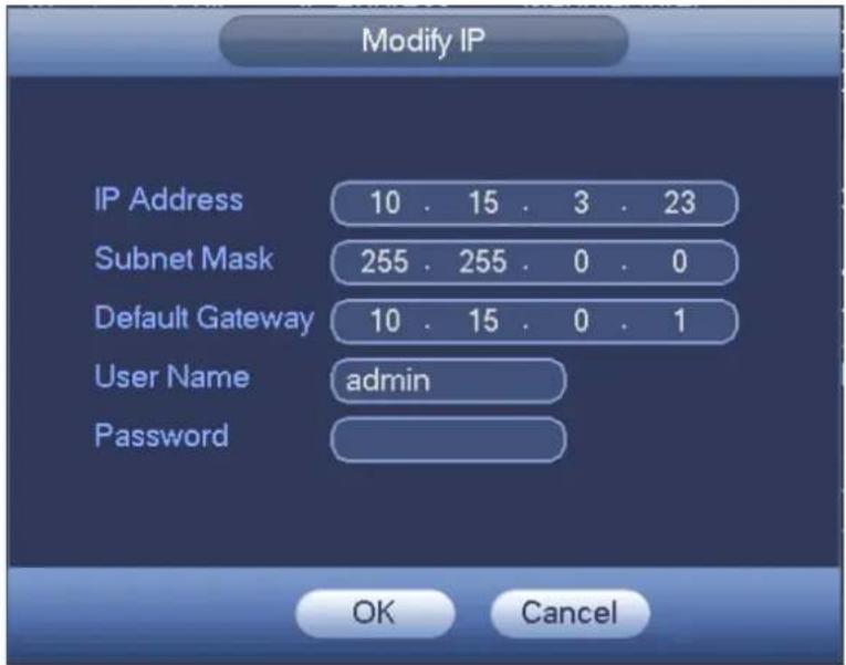
text_image
Modify IP IP Address 10 . 15 . 3 . 23 Subnet Mask 255 . 255 . 0 . 0 Default Gateway 10 . 15 . 0 . 1 User Name admin Password OK CancelFigure 4-63
You can check several devices at the same time and then click the edit button. Please check Batch modify button and then input start IP, end IP and default gateway.

text_image
Modify IP ✓ Batch Modify Start Address 10 . 15 . 3 . 23 Subnet Mask 255 . 255 . 0 . 0 Default Gateway 10 . 15 . 0 . 1 User Name admin Password OK CancelFigure 4-64
- IP Export
System can export the Added device list to your local USB device.
Holis HD Series DVR User Manual 4, 8 & 16 Channel Models
Please insert the USB device and then click the Export button; you can see the following interface. See Figure 4-65.
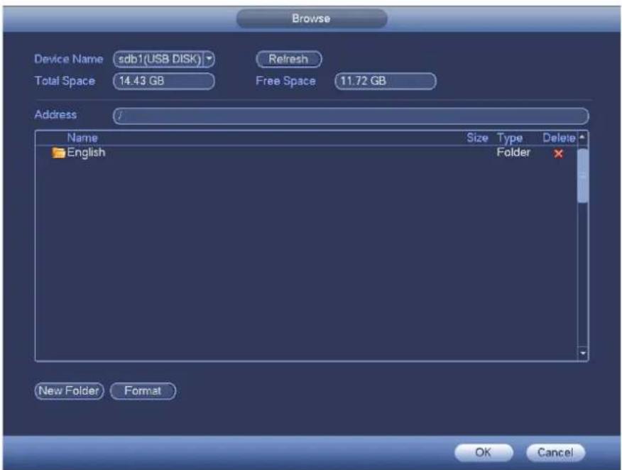
text_image
Browse Device Name:sdb1(USB DISK) Refresh Total Space 14.43 GB Free Space 11.72 GB Address Name Size Type Delete English Folder New Folder Format OK CancelFigure 4-65
Select the directory and then click the OK button. System pops up a dialogue box to remind you successfully exported. Please click OK button to exit.
Note
The exported file extension name is .CVS. The file information includes IP address, port, remote channel number, manufacturer, user name and password.
- IP Import
Click Import button, you can see the following interface. See Figure 4-66.

text_image
Browse Device Name:sdb1(USB DISK)Refresh Total Space 14.43 GB Free Space 10.63 GB Address /English Name Size Type Delete men7.bmp 2.50 MB File re333.bmp 2.50 MB File ine.bmp 2.50 MB File free.bmp 2.50 MB File fre2.bmp 2.50 MB File lr7.bmp 2.50 MB File lr8.bmp 2.50 MB File col.bmp 2.50 MB File ex2.bmp 2.50 MB File RemoteConfig_20150202143711.csv 171 B File lm2.bmp 2.50 MB File re222.bmp 2.50 MB File re3.bmp 2.50 MB File rma1.bmp 2.50 MB File en1.bmp 2.50 MB File Config Files RemoteConfig_20150202143711.csv OK CancelFigure 4-66
Select the import file and then click the OK button. System pops up a dialogue box to remind you successfully exported. Please click OK button to exit.
Note:
If the imported IP has conflicted with current added device, system pops up a dialogue box to remind you. You have two options:
- OK: Click OK button, system uses the imported setup to overlay current one.
- Cancel: Click Cancel button, system adds the new IP setup.

Important
- You can edit the exported .CVS file. Do not change the file format; otherwise it may result in import failure.
- Does not support customized protocol import and export.
● The import and export device shall have the same language format.
Channel Status
Here you can view the IPC status of the corresponding channel such as motion detect, video loss, tampering, alarm and etc. See Figure 4-67.
- IPC status: - - - - Front-end does not support. - - - - - Front-end supports. - - - - - There is alarm event from current front-end.
- Connection status: ● Connection succeeded. ● Connection failed.
- Refresh: Click it to get latest front-end channel status.
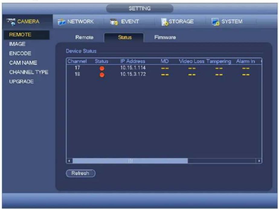
text_image
CAMERA NETWORK EVENT STORAGE SYSTEM REMOTE Remote Status Firmware IMAGE ENCODE CAM NAME CHANNEL TYPE UPGRADE Device Status Channel Status IP Address MD Video Loss Tampering Alarm In 17 ● 10.15.1.114 - - - - - - - - - - - - 18 ● 10.15.3.172 - - - - - - - - - - - -Figure 4-67
Firmware
It is to view channel, IP address, manufacturer, type, system version, SN, video input, audio input, and etc. See Figure 4-68.
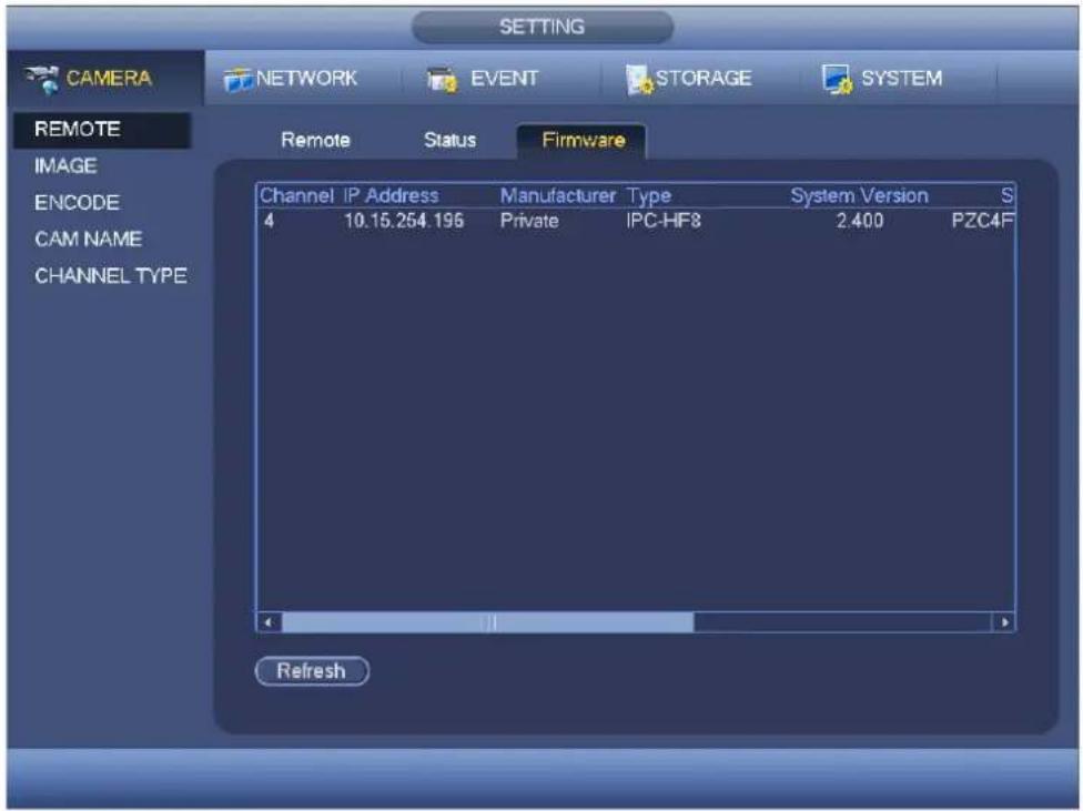
text_image
SETTING CAMERA NETWORK EVENT STORAGE SYSTEM REMOTE Remote Status Firmware IMAGE ENCODE CAM NAME CHANNEL TYPE Channel IP Address Manufacturer Type System Version S 4 10.15.254.196 Private IPC-HF8 2.400 PZC4F RefreshFigure 4-68
Image
For analog channel, the image interface is shown as in Figure 4-69. For digital channel, the image interface is shown as in Figure 4-70.
● Channel: Select a channel from the dropdown list.
- Saturation: It is to adjust monitor window saturation. The value ranges from 0 to 100. The default value is 50. The larger the number, the strong the color is. This value has no effect on the general brightness of the whole video. The video color may become too strong if the value is too high. For the grey part of the video, the distortion may occur if the white balance is not accurate. Please note the video may not be attractive if the value is too low. The recommended value ranges from 40 to 60.
- Brightness: It is to adjust monitor window bright. The value ranges from 0 to 100. The default value is 50. The larger the number is, the bright the video is. When you input the value here, the bright section and the dark section of the video will be adjusted accordingly. You can use this function when the whole video is too dark or too bright. Please note the video may become hazy if the value is too high. The recommended value ranges from 40 to 60.
- Contrast: It is to adjust monitor window contrast. The value ranges from 0 to 100. The default value is 50. The larger the number is, the higher the contrast is. You can use this function when the whole video bright is OK but the contrast is not proper. Please note the video may become hazy if the value is too low. If this value is too high, the dark section may lack brightness while the bright section may over exposure. The recommended value ranges from 40 to 60.
● Sharpness: The value here is to adjust the edge of the video. The value ranges from 0 to 100. The larger the value is, the clear the edge is and vice versa. Please note there is noise if the value here is too high. The default value is 50 and the recommended value ranges from 40 to 60.
- Mirror: It is to switch video up and bottom limit. This function is disabled by default.
- Flip: It is to switch video left and right limit. This function is disabled by default.
- BLC: It includes several options: BLC/WDR/HLC/OFF.
BLC: The device auto exposures according to the environments situation so that the darkest area of the video is cleared
WDR: For the WDR scene, this function can lower the high bright section and enhance the brightness of the low bright section. So that you can view these two sections clearly at the same time. The value ranges from 1 to 100. When you switch the camera from no-WDR mode to the WDR mode, system may lose several seconds record video.
HLC: After you enabled HLC function, the device can lower the brightness of the brightest section according to the HLC control level. It can reduce the area of the halo and lower the brightness of the whole video.
✿ OFF: It is to disable the BLC function. Please note this function is disabled by default.
- Profile: It is to set the white balance mode. It has effect on the general hue of the video. This function is on by default. You can select the different scene mode such as auto, sunny, cloudy, home, office, night, disable and etc to adjust the video to the best quality.
Auto: The auto white balance is on. System can auto compensate the color temperature to make sure the vide color is proper.
✿ Sunny: The threshold of the white balance is in the sunny mode.
Night: The threshold of the white balance is in the night mode.
✿ Customized: You can set the gain of the red/blue channel. The value reneges from 0 to 100.
● Day/night. It is to set device color and the B/W mode switch. The default setup is auto.
✨ Color: Device outputs the color video.
Auto: Device auto select to output the color or the B/W video according to the device feature (The general bright of the video or there is IR light or not.)
B/W: The device outputs the black and white video.
Sensor: It is to set when there is peripheral connected IR light.
- Image enhancement: It is to enhance video quality. The larger the value is, the clearer the video is. But the noise may become large too.
- 2D NR: It is to process the noise of the single image. The video may become soft after process. The larger the value is, the better the effect is.
- 3D NR: it is to process the multiple-frame (at least two frames). It is to use the frame information between the following two frames to reduce noise. The larger the value is, the better the effect is.

text_image
CAMERA NETWORK EVENT STORAGE SYSTEM IMAGE ENCODE CAM NAME CHANNEL TYPE Channel 1 Time Period Time Period 1 Effective Time 00:00 24:00 Saturation 50 Brightness 50 Contrast 50 Chroma 50 Sharpness 1 Image Enhan 8 2D NR 0 3D Denoise 36 Default Save Cancel ApplyFigure 4-69
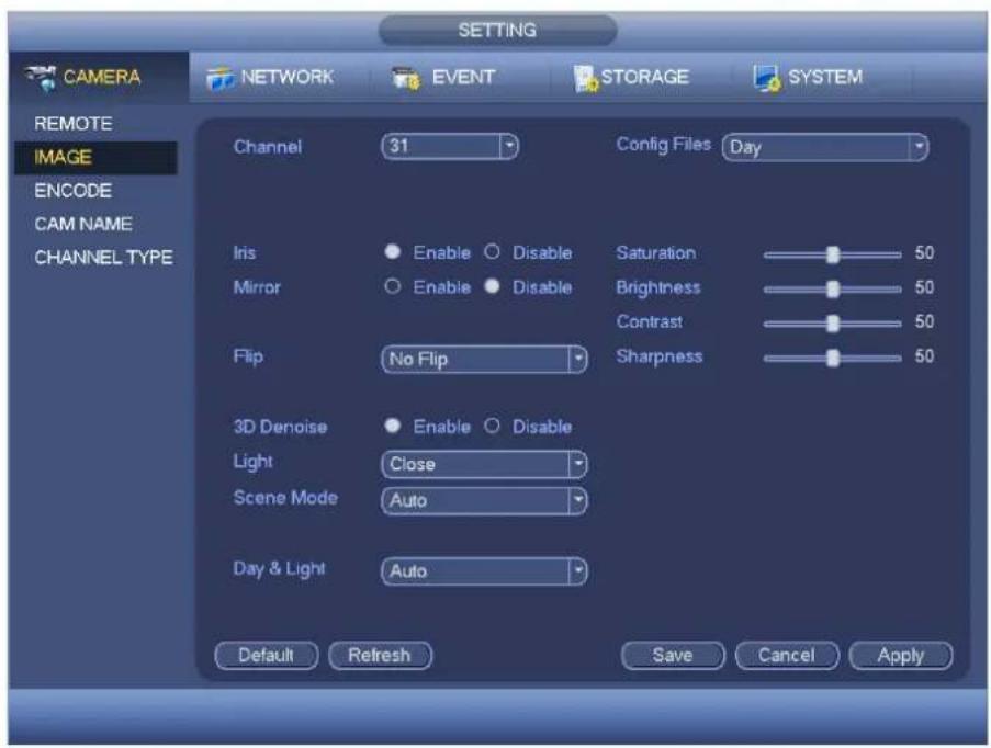
text_image
CAMERA NETWORK EVENT STORAGE SYSTEM REMOTE IMAGE ENCODE CAM NAME CHANNEL TYPE Channel 31 Config Files Day Iris Enable Disable Saturation 50 Mirror Enable Disable Brightness 50 Contrast 50 Flip No Flip Sharpness 50 3D Denoise Enable Disable Light Close Scene Mode Auto Day & Light Auto Default Refresh Save Cancel ApplyFigure 4-70
Encode
It is to set video bit stream, picture bit stream, video overlay parameter and etc.
Video
Video setting includes the following items. See Figure 4-71.
- Channel: Select the channel you want.
- SVC: SVC is so called scaled video coding. Check the box to enable this function. During the network transmission process, system discards unimportant frames when the bandwidth is not sufficient or the decode capability is low. It is to guarantee video quality and transmission fluency.
- Type: Please select from the dropdown list. There are three options: regular/motion detect/alarm. You can set the various encode parameters for different record types.
● Compression: System supports H.264 and MJPEG. - Resolution: System supports various resolutions, you can select from the dropdown list. Please note the option may vary due to different series.
● Frame rate: It ranges from 1f/s to 25f/s in NTSC mode and 1f/s to 30f/s in PAL mode.
● Bit rate type: System supports two types: CBR and VBR. In VBR mode, you can set video quality.
● Quality: There are six levels ranging from 1 to 6. The sixth level has the highest image quality. - Video/audio: You can enable or disable the video/audio.
● Audio format: Please select from the dropdown list. There are three options: G711a/G711u/PCM - Audio source: Please select from the dropdown list. There are two options: normal/HDUTC. For normal mode, the audio signal is from the Audio In port. For HDUTC mode, the audio signal is from the coaxial cable of the camera.

text_image
SETTING CAMERA NETWORK EVENT STORAGE SYSTEM REMOTE IMAGE ENCODE CAM NAME CHANNEL TYPE UPGRADE Encode Snapshot Overlay Channel 1 SVC Type Regular Sub Stream1 Compression H.264H H.264H Resolution 1080P CIF Frame Rate(FPS) 25 25 Bit Rate Type CBR CBR I Frame Interval 1 S 1 S Bit Rate(Kb/S) 4096 640 Reference Bit Rate 3584-6144Kb/S 192-1024Kb/S Audio/Video Audio Format G711a Audio Source LOCAL Default Copy Save Cancel ApplyFigure 4-71
Snapshot
Here you can set snapshot mode, picture size, quality and frequency. See Figure 4-72.
- Snapshot mode: There are two modes: regular and trigger. If you set timing mode, you need to set snapshot frequency. If you set trigger snapshot, you need to set snapshot activation operation.
● Image size: Here you can set snapshot picture size.
● Image quality: Here you can set snapshot quality. The value ranges from 1 to 6. - Interval: It is for you to set timing (schedule) snapshot interval.
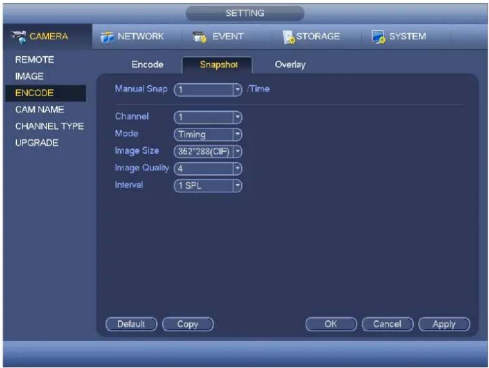
text_image
SETTING CAMERA NETWORK EVENT STORAGE SYSTEM REMOTE IMAGE ENCODE CAM NAME CHANNEL TYPE UPGRADE Encode Snapshot Overlay Manual Snap 1 /Time Channel 1 Mode Timing Image Size 352*288(CIF) Image Quality 4 Interval 1 SPL Default Copy OK Cancel ApplyFigure 4-72
Overlay
Overlay interface is shown as in Figure 4-73.
- Cover area: Here is for you to set cover area. You can drag you mouse to set proper section size. In one channel video, system max supports 4 zones in one channel.
- Preview/monitor: privacy mask has two types. Preview and Monitor. Preview means the privacy mask zone can not be viewed by user when system is in preview status. Monitor means the privacy mask zone can not be view by the user when system is in monitor status.
- Time display: You can select system displays time or not when you playback. Please click set button and then drag the title to the corresponding position in the screen.
- Channel display: You can select system displays channel number or not when you playback. Please click set button and then drag the title to the corresponding position in the screen.
- Copy: After you complete the setup, you can click Copy button to copy current setup to other channel(s). You can see an interface is shown as in Figure 4-74. You can see current channel number is grey. Please check the number to select the channel or you can check the box ALL. Please click the OK button in Figure 4-74 and Figure 4-73 respectively to complete the setup.
Please highlight icon ☐ to select the corresponding function.
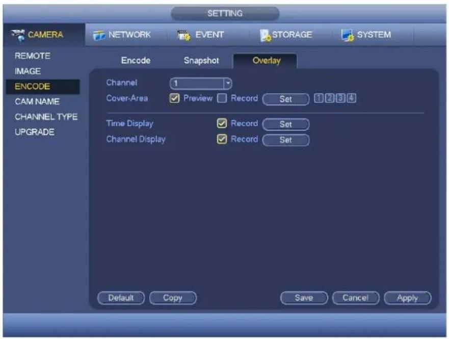
text_image
SETTING CAMERA NETWORK EVENT STORAGE SYSTEM REMOTE IMAGE ENCODE CAM NAME CHANNEL TYPE UPGRADE Encode Snapshot Overlay Channel 1 Cover-Area Preview Record Set 1 2 3 4 Time Display Record Set Channel Display Record Set Default Copy Save Cancel ApplyFigure 4-73

text_image
Copy All 1 2 3 4 OK CancelFigure 4-74
Channel Name
It is to modify channel name. It max supports 31-character. See Figure 4-75.

text_image
CAMERA NETWORK EVENT STORAGE SYSTEM REMOTE IMAGE ENCODE CAM NAME CHANNEL TYPE UPGRADE CAM 1 CAM 2 CAM 3 CAM 4 CAM 5 CAM 6 CAM 7 CAM 8 CAM 9 CAM 10 CAM 11 CAM 12 CAM 13 CAM 14 CAM 15 CAM 16 1/2 Default Save Cancel ApplyFigure 4-75
Channel Type
It is to set channel type. It supports coaxial/UTP/IP. See Figure 4-76.
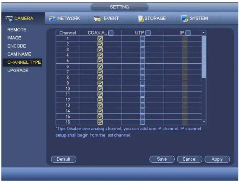
text_image
SETTING CAMERA NETWORK EVENT STORAGE SYSTEM REMOTE IMAGE ENCODE CAM NAME CHANNEL TYPE UPGRADE Channel COAXIAL UTP IP 1 ✓ □ 2 ✓ □ 3 ✓ □ 4 ✓ □ 5 ✓ □ 6 ✓ □ 7 ✓ □ 8 ✓ □ 9 ✓ □ 10 ✓ □ 11 ✓ □ 12 ✓ □ 13 ✓ □ 14 ✓ □ 15 ✓ □ 16 ✓ □ *Tips:Disable one analog channel, you can add one IP channel, IP channel setup shall begin from the last channel. Default Save Cancel ApplyFigure 4-76
Important
Add/cancel IP CAM function is for some 4/8/16-channel series product only.
- Add IP CAM: Click it; you can add corresponding X IP channels. Here X refers to the product channel amount such as 4/8/16. System needs to restart to activate new setup. See Figure 4-77.
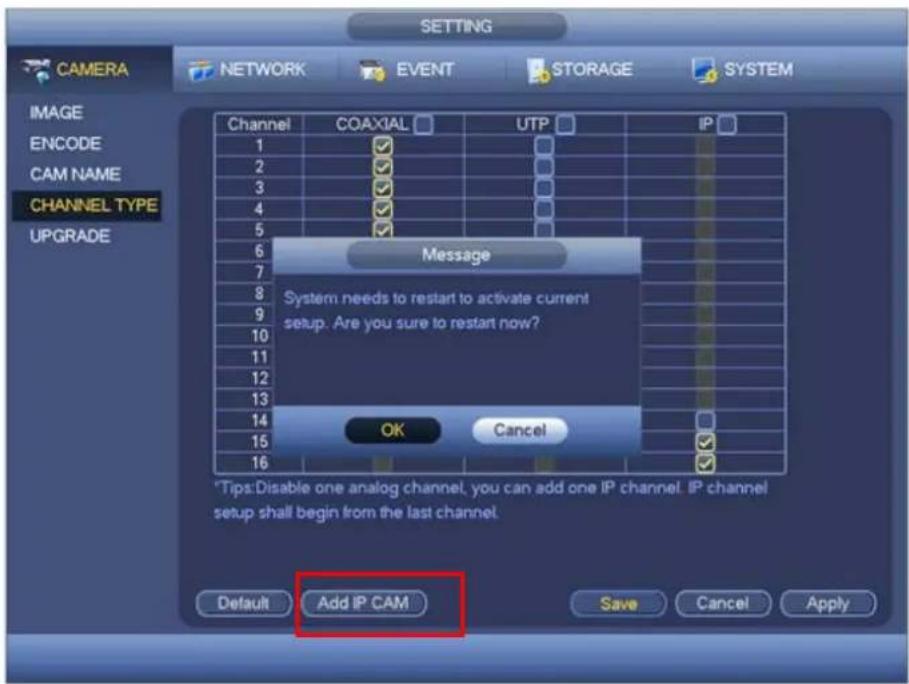
text_image
CAMERA NETWORK EVENT STORAGE SYSTEM IMAGE ENCODE CAM NAME CHANNEL TYPE UPGRADE Channel COAXIAL UTP IP Message System needs to restart to activate current setup. Are you sure to restart now? OK Cancel *Tips:Disable one analog channel, you can add one IP channel. IP channel setup shall begin from the last channel. Default Add IP CAM Save Cancel ApplyFigure 4-77
For example, there is a 4-channel analog device, after the A/D switch, it can max supports 4 analog channels and 4 IP channels. Once it has become the 3+1 mode (3 analog channels+1 IP channel), you
Add IP CAM
button, system becomes 3+5 mode (3 analog channels+5 IP channel).
- Cancel IP CAM: Click it, you can cancel IP channel. System needs to restart to restore original status.
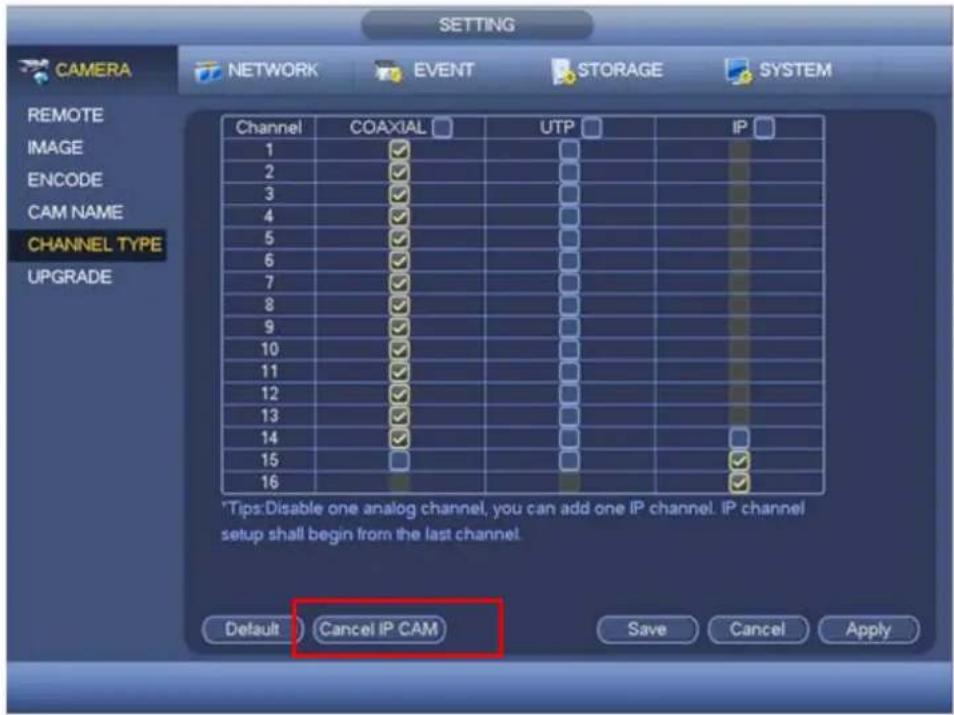
text_image
SETTING CAMERA NETWORK EVENT STORAGE SYSTEM REMOTE IMAGE ENCODE CAM NAME CHANNEL TYPE UPGRADE Channel COAXIAL UTP IP 1 ✓ □ 2 ✓ □ 3 ✓ □ 4 ✓ □ 5 ✓ □ 6 ✓ □ 7 ✓ □ 8 ✓ □ 9 ✓ □ 10 ✓ □ 11 ✓ □ 12 ✓ □ 13 ✓ □ 14 ✓ □ 15 □ □ 16 ✓ □ *Tips:Disable one analog channel, you can add one IP channel. IP channel setup shall begin from the last channel. Default Cancel IP CAM Save Cancel ApplyFigure 4-78
Upgrade
It is to update the camera.
From main menu->setting->camera->remote upgrade, the interface is shown as below. See Figure 4-79.
Click Browse button and then select the upgrade file. Then select a channel (or you can select device type filter to select several devices at the same time.)
Click Start upgrade button to update. You can see the corresponding dialogue once the upgrade is finish.
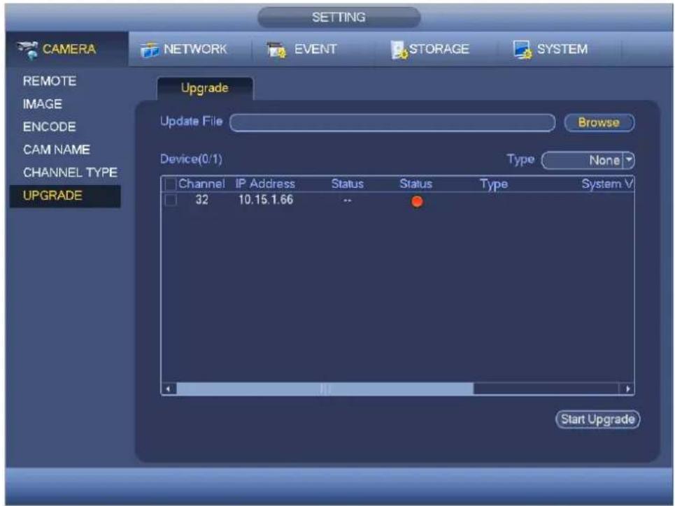
text_image
CAMERA NETWORK EVENT STORAGE SYSTEM REMOTE IMAGE ENCODE CAM NAME CHANNEL TYPE UPGRADE Setting Upgrade Update File Browse Device(0/1) Type None Channel IP Address Status Status Type System V 32 10.15.1.66 -- Start UpgradeFigure 4-79
Network
TCP/IP
The interface is shown as in Figure 4-80
- IP Version: There are two options: IPv4 and IPv6. Right now, system supports these two IP address format and you can access via them.
- MAC address: The host in the LAN can get a unique MAC address. It is for you to access in the LAN. It is read-only.
- IP address: Here you can use up/down button (▲▼) or input the corresponding number to input IP address. Then you can set the corresponding subnet mask the default gateway.
- Default gateway: Here you can input the default gateway. Please note system needs to check the validity of all IPv6 addresses. The IP address and the default gateway shall be in the same IP section. That is to say, the specified length of the subnet prefix shall have the same string.
- DHCP: It is to auto search IP. When enable DHCP function, you can not modify IP/Subnet mask /Gateway. These values are from DHCP function. If you have not enabled DHCP function, IP/Subnet mask/Gateway display as zero. You need to disable DHCP function to view current IP information. Besides, when PPPoE is operating, you can not modify IP/Subnet mask /Gateway.
- MTU: It is to set MTU value of the network adapter. The value ranges from 1280-7200 bytes. The default setup is 1500 bytes. Please note MTU modification may result in network adapter reboot and network becomes off. That is to say, MTU modification can affect current network service. System may pop up dialog box for you to confirm setup when you want to change MTU setup. Click OK button to confirm current reboot, or you can click Cancel button to terminate current modification. Before the modification, you can check the MTU of the gateway; the MTU of the DVR shall be the same as or is lower than the MTU of the gateway. In this way, you can reduce packets and enhance network transmission efficiency.
The following MTU value is for reference only.
1500: Ethernet information packet max value and it is also the default value. It is the typical setup when there is no PPPoE or VPN. It is the default setup of some router, switch or the network adapter.
✦ 1492: Recommend value for PPPoE.
✦ 1468: Recommend value for DHCP.
● Preferred DNS server: DNS server IP address.
- Alternate DNS server: DNS server alternate address.
● Transfer mode: Here you can select the priority between fluency/video qualities.
● LAN download: System can process the downloaded data first if you enable this function. The download speed is 1.5X or 2.0X of the normal speed.
● LAN download: System can process the downloaded data first if you enable this function. The download speed is 1.5X or 2.0X of the normal speed.
After completing all the setups please click save button, system goes back to the previous menu.
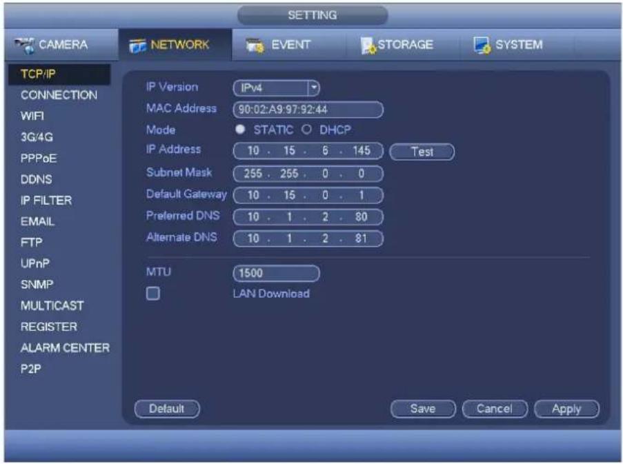
text_image
SETTING CAMERA NETWORK EVENT STORAGE SYSTEM TCP/IP CONNECTION WIFI 3G/4G PPPoE DDNS IP FILTER EMAIL FTP UPnP SNMP MULTICAST REGISTER ALARM CENTER P2P IP Version IPv4 MAC Address 90:02:A9:97:92:44 Mode STATIC DHCP IP Address 10 . 15 . 6 . 145 Test Subnet Mask 255 . 255 . 0 . 0 Default Gateway 10 . 15 . 0 . 1 Preferred DNS 10 . 1 . 2 . 80 Alternate DNS 10 . 1 . 2 . 81 MTU 1500 LAN Download Default Save Cancel ApplyFigure 4-80
Connection
The connection setup interface is shown as in Figure 4-81.
● Max connection: system support maximal 128 users. 0 means there is no connection limit.
● TCP port: Default value is 37777.
Holis HD Series DVR User Manual 4, 8 & 16 Channel Models
- UDP port: Default value is 37778.
- HTTP port: Default value is 80.
- HTTPS port: Default value is 443.
- RTSP port: Default value is 554.
Important: System needs to reboot after you changed and saved any setup of the above four ports. Please make sure the port values here do not conflict.

text_image
CAMERA NETWORK EVENT STORAGE SYSTEM TCP/IP CONNECTION Max Connection 128 (0 -128) TCP Port 37777 (1025 - 65535) UDP Port 37778 (1025 - 65535) HTTP Port 80 (1 - 65535) HTTPS Port 443 (1 - 65535) RTSP Port 554 (1 - 65535) EMAIL FTP UPnP SNMP MULTICAST REGISTER ALARM CENTRE P2P Default Save Cancel ApplyFigure 4-81
PPPoE
PPPoE interface is shown as in Figure 4-82.
Input "PPPoE name" and "PPPoE password" you get from your ISP (Internet service provider).
Click save button, you need to restart to activate your configuration.
After rebooting, DVR will connect to internet automatically. The IP in the PPPoE is the DVR dynamic value. You can access this IP to visit the unit.

text_image
SETTING CAMERA NETWORK EVENT STORAGE SYSTEM TCP/IP CONNECTION WIFI 3G PPPoE DDNS IP FILTER EMAIL FTP UPnP SNMP MULTICAST REGISTER ALARM CENTRE P2P Enable User Name Password IP Address 0 . 0 . 0 . 0 0 . 0 . 0 . 0 Default OK Cancel ApplyFigure 4-82
DDNS Setup
DDNS setup interface is shown as in Figure 4-83.
You need a PC of fixed IP in the internet and there is the DDNS software running in this PC. In other words, this PC is a DNS (domain name server).
In network DDNS, please select DDNS type and highlight enable item. Then please input your PPPoE name you get from you IPS and server IP (PC with DDNS). Click save button and then reboot system.
Click save button, system prompts for rebooting to get all setup activated.
After rebooting, open IE and input as below:
http://(DDNS server IP)/(virtual directory name)/webtest.htm
e.g.: http://10.6.2.85/DVR_DDNS/webtest.htm.)
Now you can open DDNSServer web search page.
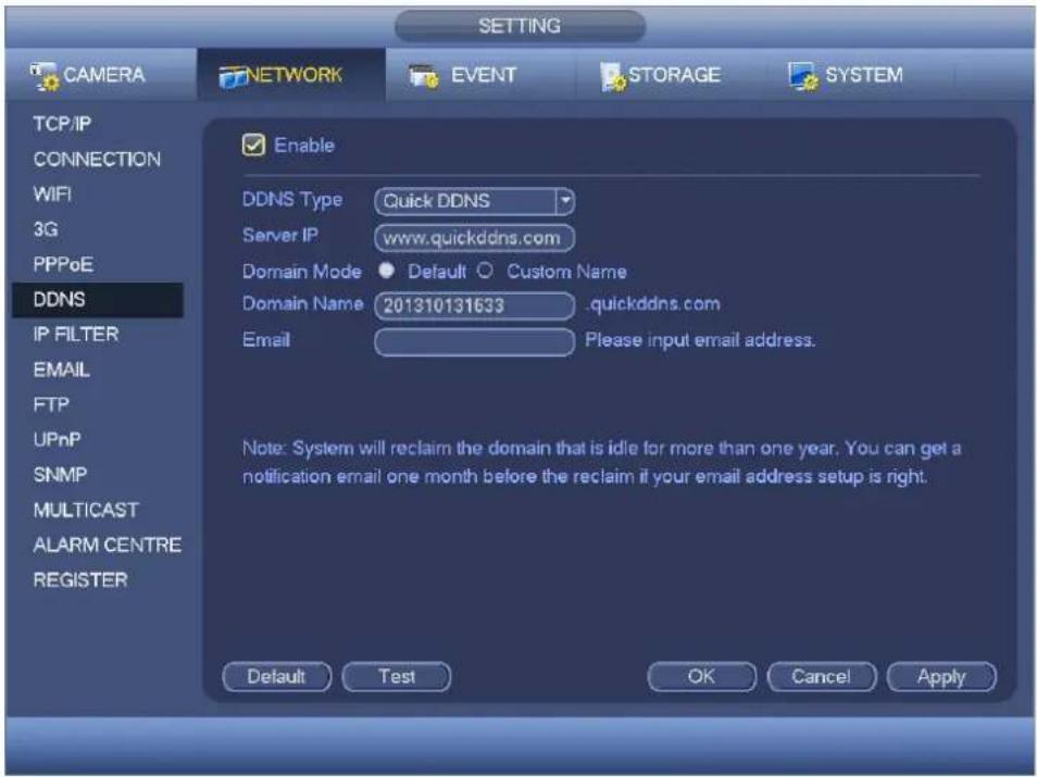
text_image
SETTING CAMERA NETWORK EVENT STORAGE SYSTEM TCP/IP CONNECTION WIFI 3G PPPoE DDNS IP FILTER EMAIL FTP UPnP SNMP MULTICAST ALARM CENTRE REGISTER Enable DDNS Type Quick DDNS Server IP www.quickddns.com Domain Mode Default Custom Name Domain Name 201310131633 .quickddns.com Email Please input email address. Note: System will reclaim the domain that is idle for more than one year. You can get a notification email one month before the reclaim if your email address setup is right. Default Test OK Cancel ApplyFigure 4-83
Please note DDNS type includes: CN99 DDNS, NO-IP DDNS, Quick DDNS, Dyndns DDNS and sysdns DDNS. All the DDNS can be valid at the same time, you can select as you requirement.
Private DDNS function shall work with special DDNS server and special Professional Surveillance Software (PSS).
Quick DDNS and Client-end Introduction
1) Background Introduction
Device IP is not fixed if you use ADSL to login the network. The DDNS function allows you to access the DVR via the registered domain name. Besides the general DDNS, the Quick DDNS works with the device from the manufacturer so that it can add the extension function.
2) Function Introduction
The quick DDNS client has the same function as other DDNS client end. It realizes the bonding of the domain name and the IP address. Right now, current DDNS server is for our own devices only. You need to refresh the bonding relationship of the domain and the IP regularly. There is no user name, password or the ID registration on the server. At the same time, each device has a default domain name (Generated by MAC address) for your option. You can also use customized valid domain name (has not registered.).
3) Operation
Before you use Quick DDNS, you need to enable this service and set proper server address, port value and domain name.
- Server address: www.quickddns.com
- Port number: 80
- Domain name: There are two modes: Default domain name and customized domain name.
Except default domain name registration, you can also use customized domain name (You can input your self-defined domain name.) After successful registration, you can use domain name to login installed of the device IP.
- User name: It is optional. You can input your commonly used email address.
Important
- Do not register frequently. The interval between two registrations shall be more than 60 seconds. Too many registration requests may result in server attack.
- System may take back the domain name that is idle for one year. You can get a notification email before the cancel operation if your email address setup is OK.
IP Filter
IP filter interface is shown as in Figure 4-84. You can add IP in the following list. The list supports max 64 IP addresses. System supports valid address of IPv4 and IPv6. Please note system needs to check the validity of all IPv6 addresses and implement optimization.
After you enabled trusted sites function, only the IP listed below can access current DVR.
If you enable blocked sites function, the following listed IP addresses can not access current DVR.
- Enable: Highlight the box here, you can check the trusted site function and blocked sites function. You can not see these two modes if the Enable button is grey.
- Type: You can select trusted site and blacklist from the dropdown list. You can view the IP address on the following column.
- Start address/end address: Select one type from the dropdown list, you can input IP address in the start address and end address. Now you can click Add IP address or Add IP section to add.
a) For the newly added IP address, it is in enable status by default. Remove the √ before the item, and then current item is not in the list.
b) System max supports 64 items.
c) Address column supports IPv4 or IPv6 format. If it is IPv6 address, system can optimize it. For example, system can optimize aa:0000: 00: 00aa: 00aa: 00aa: 00aa as aa:: aa: aa: aa: aa: aa: aa.
d) System automatically removes space if there is any space before or after the newly added IP address.
e) System only checks start address if you add IP address. System check start address and end address if you add IP section and the end address shall be larger than the start address.
f) System may check newly added IP address exists or not. System does not add if input IP address does not exist.
- Delete: Click it to remove specified item.
- Edit: Click it to edit start address and end address. See Figure 4-85. System can check the IP address validity after the edit operation and implement IPv6 optimization.
- Default: Click it to restore default setup. In this case, the trusted sites and blocked sites are both null.
Note:
- If you enabled trusted sites, only the IP in the trusted sites list can access the device.
- If you enabled blocked sites, the IP in the blocked sites can not access the device.
● System supports add MAC address.

text_image
SETTING CAMERA NETWORK EVENT STORAGE SYSTEM TCP/IP CONNECTION WIFI 3G PPPoE DDNS IP FILTER EMAIL FTP UPnP SNMP MULTICAST REGISTER ALARM CENTRE P2P Enable Type Trusted Sites Start Address Add IP Address) End Address Add IP Segment) Start Address End Address Edit Delete Default OK Cancel ApplyFigure 4-84

text_image
Edit Start Address 10.15.6.140 123 End Address 10.15.6.145 OK CancelFigure 4-85
The email interface is shown as below. See Figure 4-86.
- SMTP server: Please input your email SMTP server IP here.
● Port: Please input corresponding port value here. - User name: Please input the user name to login the sender email box.
- Password: Please input the corresponding password here.
- Sender: Please input sender email box here.
- Title: Please input email subject here. System support English character and Arabic number. Max 32-digit.
- Receiver: Please input receiver email address here. System max supports 3 email boxes. System automatically filters same addresses if you input one receiver repeatedly.
- SSL enable: System supports SSL encryption box.
- Interval: The send interval ranges from 0 to 3600 seconds. 0 means there is no interval.
Holis HD Series DVR User Manual 4, 8 & 16 Channel Models
● Health email enable: Please check the box here to enable this function. This function allows the system to send out the test email to check the connection is OK or not.
- Interval: Please check the above box to enable this function and then set the corresponding interval. System can send out the email regularly as you set here. Click the Test button, you can see the corresponding dialogue box to see the email connection is OK or not.
Please note system will not send out the email immediately when the alarm occurs. When the alarm, motion detection or the abnormality event activates the email, system sends out the email according to the interval you specified here. This function is very useful when there are too many emails activated by the abnormality events, which may result in heavy load for the email server.

text_image
SETTING CAMERA NETWORK EVENT STORAGE SYSTEM TCP/IP CONNECTION WIFI 3G/4G PPPoE DDNS IP FILTER EMAIL FTP UPnP SNMP MULTICAST REGISTER ALARM CENTER P2P Enable SMTP Server MailServer Port 25 Anonymous User Name Password Receiver Sender Subject HCVR ALERT Attachment ✓ Encrypt Type NONE Interval 120 sec. Health Enable Interval 60 min. Default Test Save Cancel ApplyFigure 4-86
FTP
You need to download or buy FTP service tool (such as Ser-U FTP SERVER) to establish FTP service. Please install Ser-U FTP SERVER first. From "start" -> "program" -> Serv-U FTP Server -> Serv-U Administrator. Now you can set user password and FTP folder. Please note you need to grant write right to FTP upload user. See Figure 4-87.
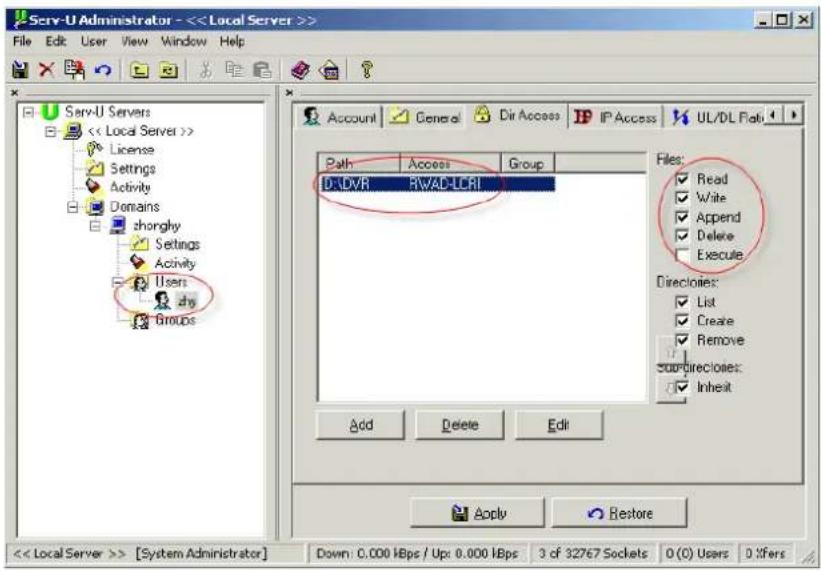
text_image
Serv-U Administrator - <Figure 4-87
You can use a PC or FTP login tool to test setup is right or not.
For example, you can login user ZHY to H140H140H140HTUFTP://10.10.7.7UTH and then test it can modify or delete folder or not. See Figure 4-88.

text_image
Internet Explorer To log on to this FTP server, type a user name and password. FTP server: 10.10.7.7 User name: Password: After you log on, you can add this server to your Favorites and return to it easily. Log on anonymously Log On CancelFigure 4-88
System also supports upload multiple DVRs to one FTP server. You can create multiple folders under this FTP.
FTP interface is shown as in Figure 4-89.
Please highlight the icon ☐ in front of Enable to activate FTP function.
Here you can input FTP server address, port and remote directory. When remote directory is null, system automatically create folders according to the IP, time and channel.
User name and password is the account information for you to login the FTP.
File length is upload file length. When setup is larger than the actual file length, system will upload the whole file. When setup here is smaller than the actual file length, system only uploads the set length and auto ignore the left section. When interval value is 0, system uploads all corresponding files.
After completed channel and weekday setup, you can set two periods for one each channel.
Click the Test button, you can see the corresponding dialogue box to see the FTP connection is OK or not.

text_image
SETTING CAMERA NETWORK EVENT STORAGE SYSTEM TCP/IP CONNECTION WIFI 3G PPPoE DDNS IP FILTER EMAIL FTP UPnP SNMP MULTICAST REGISTER ALARM CENTRE P2P Enable Server IP 0 . 0 . 0 . 0 Port 21 User Name Password Anonymous Remote Directory File Length 0 M Image Upload Interval 2 s Channel 1 Weekday Thu Alarm Motion Regular Time Period 1 00 :00 - 24 :00 Time Period 2 00 :00 - 24 :00 Default Test OK Cancel ApplyFigure 4-89
UPnP
The UPNP protocol is to establish a mapping relationship between the LAN and the WAN. Please input the router IP address in the LAN in Figure 4-80. See Figure 4-90.
- UPNP on/off: Turn on or off the UPNP function of the device.
- Status: When the UPNP is offline, it shows as "Unknown". When the UPNP works it shows "Success"
- Router LAN IP: It is the router IP in the LAN.
- WAN IP: It is the router IP in the WAN.
- Port Mapping list: The port mapping list here is the one to one relationship with the router's port mapping setting.
- List:
Service name: Defined by user.
✨ Protocol: Protocol type
Internal port: Port that has been mapped in the router.
External port: Port that has been mapped locally.
- Default: UPNP default port setting is the HTTP, TCP and UDP of the DVR.
- Add to the list: Click it to add the mapping relationship.
- Delete: Click it to remove one mapping item.
Double click one item; you can change the corresponding mapping information. See Figure 4-91.
Important:
When you are setting the router external port, please use 1024\~5000 port. Do not use well-known port 1\~255 and the system port 256\~1023 to avoid conflict.
For the TCP and UDP, please make sure the internal port and external port are the same to guarantee the proper data transmission.

text_image
SETTING CAMERA NETWORK EVENT STORAGE SYSTEM TCP/IP CONNECTION WIFI 3G PPPoE DDNS IP FILTER EMAIL FTP UPnP SNMP MULTICAST REGISTER ALARM CENTRE P2P PAT Enable Disable UPnP Status Router LAN IP 0 . 0 . 0 . 0 WAN IP 0 . 0 . 0 . 0 PAT Table 7 Service Name Protocol Int.Port Ext.Port 1 HTTP TCP 80 80 2 TCP TCP 37777 37777 3 UDP UDP 37778 37778 4 RTSP UDP 554 554 5 RTSP TCP 554 554 6 SNMP UDP 161 161 7 HTTPS TCP 443 443 Default Add Delete OK Cancel ApplyFigure 4-90
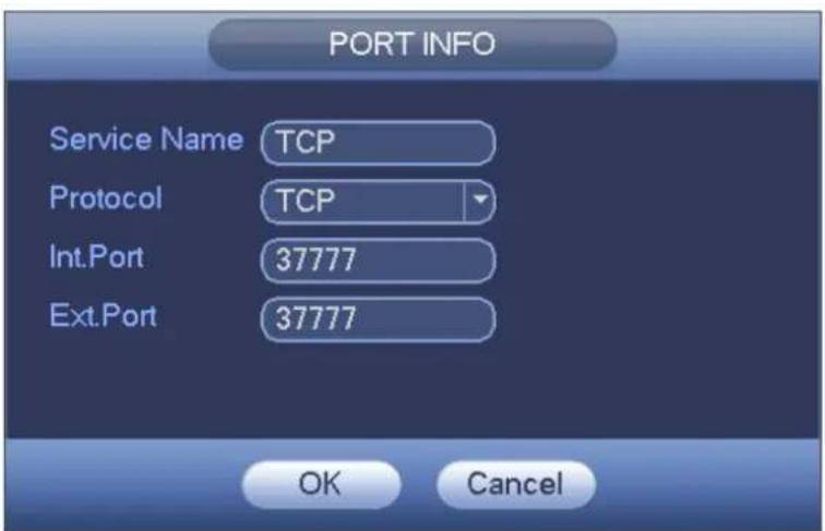
text_image
PORT INFO Service Name TCP Protocol TCP Int.Port 37777 Ext.Port 37777 OK CancelFigure 4-91
SNMP
SNMP is an abbreviation of Simple Network Management Protocol. It provides the basic network management frame of the network management system. The SNMP widely used in many environments. It is used in many network device, software and system.
You can set in the following interface. See Figure 4-92.

text_image
SETTING CAMERA NETWORK EVENT STORAGE SYSTEM TCP/IP CONNECTION WIFI 3G PPPoE DDNS IP FILTER EMAIL FTP UPnP SNMP MULTICAST REGISTER ALARM CENTRE P2P Enable SNMP Version V1 V2 SNMP Port 161 Read-Community public Write-Community private Trap Address Trap Port 162 Default Save Cancel ApplyFigure 4-92
Please enable the SNMP function. Use the corresponding software tool (MIB Builder and MG-SOFT MIB Browser. You still need two MIB file: BASE-SNMP-MIB, DVR-SNMP-MIB) to connect to the device. You can get the device corresponding configuration information after successfully connection.
Please follow the steps listed below to configure.
- In Figure 4-92, check the box to enable the SNMP function. Input the IP address of the PC than is running the software in the Trap address. You can use default setup for the rest items.
- Compile the above mentioned two MIB file via the software MIB Builder.
- Run MG-SOFT MIB Browser to load the file from the previous step to the software.
- Input the device IP you want to manage in the MG-SOFT MIB Browser. Please set the corresponding version for your future reference.
- Open the tree list on the MG-SOFT MIB Browser; you can get the device configuration. Here you can see the device has how many video channels, audio channels, application version and etc.
Note
Port conflict occurs when SNMP port and Trap port are the same.
Multicast
Multicast setup interface is shown as in Figure 4-93.

text_image
SETTING CAMERA NETWORK EVENT STORAGE SYSTEM TCP/IP CONNECTION WIFI 3G PPPoE DDNS IP FILTER EMAIL FTP UPnP SNMP MULTICAST REGISTER ALARM CENTRE P2P Enable IP Address 239 . 255 . 42 . 42 Port 36666 Default OK Cancel ApplyFigure 4-93
Here you can set a multiple cast group. Please refer to the following sheet for detailed information.
- IP multiple cast group address
-224.0.0.0-239.255.255.255
-“D” address space
● The higher four-bit of the first byte="1110"
● Reserved local multiple cast group address
-224.0.0.0-224.0.0.255
-TTL=1 When sending out telegraph
-For example
224.0.0.1 All systems in the sub-net
224.0.0.2 All routers in the sub-net
224.0.0.4 DVMRP router
224.0.0.5 OSPF router
224.0.0.13 PIMv2 router
● Administrative scoped addressees
-239.0.0.0-239.255.255.255
-Private address space
● Like the single broadcast address of RFC1918
● Can not be used in Internet transmission
● Used for multiple cast broadcast in limited space.
Except the above mentioned addresses of special meaning, you can use other addresses. For example:
Multiple cast IP: 235.8.8.36
Multiple cast PORT: 3666.
Holis HD Series DVR User Manual 4, 8 & 16 Channel Models
After you logged in the Web, the Web can automatically get multiple cast address and add it to the multiple cast groups. You can enable real-time monitor function to view the view.
Please note multiple cast function applies to special series only.
P2P
You can use your cell phone to scan the QR code and add it to the cell phone client.
Via the SN from scanning the QR code, you can access the device in the WAN. Please refer to the P2P operation manual included in the resources CD.
From main menu->Setting->Network->P2P, you can go to the following interface, the P2P interface is shown as in Figure 4-96.

text_image
SETTING CAMERA NETWORK EVENT STORAGE SYSTEM TCP/IP CONNECTION WIFI 3G/4G PPPoE DDNS IP FILTER EMAIL FTP UPnP SNMP MULTICAST REGISTER ALARM CENTER P2P Enable Status Offline Device SN 1E025A2YAZT9012 Default Save Cancel ApplyFigure 4-94
- Android:
Open Google Play app in your smart phone. Search gDMSS Lite or gDMSS Plus, download it and install.
- iOS:
Open App Store app in your smart phone. Search iDMSS Lite or iDMSS Plus, download it and install.
Please follow the steps listed below.

- Open App; tap to go to the Liv preview.
- Tap at the top left corner, you can see the main menu.
Tap Device manager button, you can use several modes (P2P/DDNS/IP and etc) to add the device.
Click to save current setup. Tap Start Live preview to view all-channel video from the connected device.
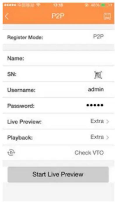
text_image
P2P Register Mode: P2P Name: SN: Username: admin Password: •••••• Live Preview: Extra > Playback: Extra > Check VTO Start Live PreviewFigure 4-95
Event
Detect
In the main menu, from Setting->Event->Detect, you can see motion detect interface. See Figure 4-98. There is three detection types: motion detection, video loss, tampering.
- The video loss has no detection region and sensitivity setup and tampering has no detection region setup.
- You can see motion detect icon if current channel has enabled motion detect alarm.
- You can drag you mouse to set motion detect region. Please click OK button to save current region setup. Right click mouse to exit current interface.
- For digital channel, the detect function refers to support detection function of the front-end and support local activation function. The front-end can get enable/disable status, sensitivity and region setup. You can get corresponding prompt if front-end can not get the above information. You can change front-end setup if it can get.
Motion Detect
After analysis video, system can generate a video loss alarm when the detected moving signal reached the sensitivity you set here.
Detection menu is shown as below. See Figure 4-98.
● Event type: From the dropdown list you can select motion detection type.
- Channel: Select a channel from the dropdown list to set motion detect function.
● Enable: Check the box here to enable motion detect function.
- Region: Click select button, the interface is shown as in Figure 4-99. Here you can set motion detection zone. There are four zones for you to set. Please select a zone first and then left drag the mouse to select a zone. The corresponding color zone displays different detection zone. You can click Fn button to switch between the arm mode and disarm mode. In arm mode, you can click the direction buttons to move the green rectangle to set the motion detection zone. After you completed the setup, please click ENTER button to exit current setup. Do remember click save button to save current setup. If you click ESC button to exit the region setup interface system will not save your zone setup.
● Sensitivity: System supports 6 levels. The sixth level has the highest sensitivity.
- Anti-dither: Here you can set anti-dither time. The value ranges from 5 to 600s. The anti-dither time refers to the alarm signal lasts time. It can be seen as the alarm signal activation stays such as the buzzer, tour, PTZ activation, snapshot, channel record. The stay time here does not include the latch time. During the alarm process, the alarm signal can begin an anti-dither time if system detects the local alarm again. The screen prompt, alarm upload, email and etc will not be activated. For example, if you set the anti-dither time as 10 second, you can see the each activation may last 10s if the local alarm is activated. During the process, if system detects another local alarm signal at the fifth second, the buzzer, tour, PTZ activation, snapshot, record channel will begin another 10s while the screen prompt, alarm upload, email will not be activated again. After 10s, if system detects another alarm signal, it can generate an alarm since the anti-dither time is out.
- Period: Click set button, you can see an interface is shown as in Figure 4-101. Here you can set motion detect period. System only enables motion detect operation in the specified periods. It is not for video loss or the tampering. There are two ways for you to set periods. Please note system only supports 6 periods in one day.
In Figure 4-101, Select icon of several dates, all checked items can be edited together. Now
the icon is shown as Click to delete a record type from one period.
In Figure 4-101. Click button after one date or a holiday, you can see an interface shown as in Figure 4-102. There are four record types: regular, motion detection (MD), Alarm, MD & alarm.
● Alarm output: when an alarm occurs, system enables peripheral alarm devices.
- Latch: when motion detection complete, system auto delays detecting for a specified time. The value ranges from 1-300(Unit: second)
- Show message: System can pop up a message to alarm you in the local host screen if you enabled this function.
- Alarm upload: System can upload the alarm signal to the network (including alarm centre) if you enabled current function.
- Send email: System can send out email to alert you when an alarm occurs.
- Record channel: System auto activates motion detection channel(s) to record once an alarm occurs. Please make sure you have set MD record in Schedule interface(Main Menu->Setting->Schedule) and schedule record in manual record interface(Main Menu->Advanced->Manual Record)
- PTZ activation: Here you can set PTZ movement when an alarm occurs. Such as go to preset, tour &pattern when there is an alarm. Click “select” button, you can see an interface is shown as in Figure 4-100.
Holis HD Series DVR User Manual 4, 8 & 16 Channel Models
- Record Delay: System can delay the record for specified time after alarm ended. The value ranges from 10s to 300s.
● Tour: Here you can enable tour function when alarm occurs. System one-window tour. - Snapshot: You can enable this function to snapshot image when a motion detect alarm occurs.
- Buzzer: Highlight the icon to enable this function. The buzzer beeps when alarm occurs.
- Test: Click it to test current motion detect setup (do not need to save). Click Select button after Region, you can set motion detect area.
Please highlight icon ☐ to select the corresponding function. After all the setups please click save button, system goes back to the previous menu.
Note:
In motion detection mode, you can not use copy/paste to set channel setup since the video in each channel may not be the same.
In Figure 4-99, you can left click mouse and then drag it to set a region for motion detection. Click Fn to switch between arm/withdraw motion detection. After setting, click enter button to exit.

text_image
CAMERA NETWORK EVENT STORAGE SYSTEM VIDEO DETECT ALARM ABNORMALITY ALARM OUTPUT Motion Detect Video Loss Tampering Diagnosis Channel 1 Region Set Enable Period Set Anti-dither 5 sec. ✓ Alarm Out 1 2 3 Latch 10 sec. ✓ Show Message ✓ Alarm Upload Send Email ✓ Record Channel 1 2 3 4 5 6 7 8 9 10 11 12 13 14 15 16 ✓ PTZ Activation Set Delay 10 sec. ✓ Tour 1 2 3 4 5 6 7 8 9 10 11 12 13 14 15 16 ✓ Snapshot 1 2 3 4 5 6 7 8 9 10 11 12 13 14 15 16 ✓ Video Matrix ✓ Buzzer ✓ Log ✓ Voice Prompts File Name None Default Copy Test Save Cancel ApplyFigure 4-96
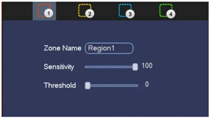
text_image
Zone Name Region1 Sensitivity 100 Threshold 0Figure 4-97
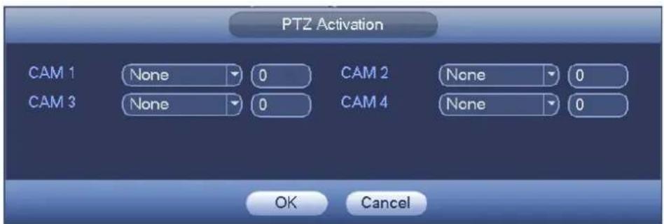
text_image
PTZ Activation CAM 1 None 0 CAM 2 None 0 CAM 3 None 0 CAM 4 None 0 OK CancelFigure 4-98

text_image
Setup All Sun Mon Tue Wed Thu Fri Sat 0 2 4 6 8 10 12 14 16 18 20 22 24 Setup Setup Setup Setup Setup Setup Setup Setup Default OK CancelFigure 4-99

text_image
Time Period Current Date: Sun Period 1 00 : 00 - 24 : 00 ✓ Period 2 00 : 00 - 24 : 00 Period 3 00 : 00 - 24 : 00 Period 4 00 : 00 - 24 : 00 Period 5 00 : 00 - 24 : 00 Period 6 00 : 00 - 24 : 00 Copy All Sun Mon Tue Wed Thu Fri Sa SaveFigure 4-100
Motion detect here only has relationship with the sensitivity and region setup. It has no relationship with other setups.
Video Loss
In Figure 4-98, select video loss from the type list. You can see the interface is shown as in Figure 4-103. This function allows you to be informed when video loss phenomenon occurred. You can enable alarm output channel and then enable show message function.
Tips:
You can enable preset/tour/pattern activation operation when video loss occurs.
Please refer to motion detection for detailed information.
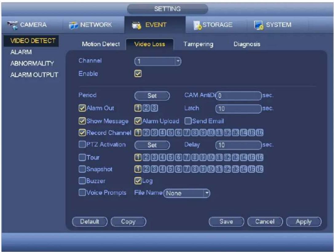
text_image
SETTING CAMERA NETWORK EVENT STORAGE SYSTEM VIDEO DETECT Motion Detect Video Loss Tampering Diagnosis ALARM ABNORMALITY ALARM OUTPUT Channel 1 Enable Period Set CAM AntiD10 sec. ✓ Alarm Out 1 2 3 Latch 10 sec. ✓ Show Message ✓ Alarm Upload Send Email ✓ Record Channel 1 2 3 4 5 6 7 8 9 10 11 12 13 14 15 16 PTZ Activation Set Delay 10 sec. Tour 1 2 3 4 5 6 7 8 9 10 11 12 13 14 15 16 Snapshot 1 2 3 4 5 6 7 8 9 10 11 12 13 14 15 16 Buzzer ✓ Log Voice Prompts File Name None Default Copy Save Cancel ApplyFigure 4-101
Tampering
When someone viciously masks the lens, or the output video is in one-color due to the environments light change, the system can alert you to guarantee video continuity. Tampering interface is shown as in Figure 4-104. You can enable “Alarm output” or “Show message” function when tampering alarm occurs.
- Sensitivity: The value ranges from 1 to 6. It mainly concerns the brightness. The level 6 has the higher sensitivity than level 1. The default setup is 3.
Tips:
You can enable preset/tour/pattern activation operation when video loss occurs.
Please refer to motion detection for detailed information.
Note:
- In Detect interface, copy/paste function is only valid for the same type, which means you can not copy a channel setup in video loss mode to tampering mode.
- About Default function. Since detection channel and detection type may not be the same, system can only restore default setup of current detect type. For example, if you click Default button at the tampering interface, you can only restore default tampering setup. It is null for other detect types.
- System only enables tampering function during the period you set here. It is null for motion detect or video loss type.

text_image
SETTING CAMERA NETWORK EVENT STORAGE SYSTEM VIDEO DETECT Motion Detect Video Loss Tampering Diagnosis ALARM ABNORMALITY ALARM OUTPUT Channel 1 Enable ✓ Sensitivity 3 Period Set CAM AntiDi 0 sec. ✓ Alarm Out 1 2 3 Latch 10 sec. ✓ Show Message ✓ Alarm Upload Send Email ✓ Record Channel 1 2 3 4 5 6 7 8 9 10 11 12 13 14 15 16 ✓ PTZ Activation Set Delay 10 sec. ✓ Tour 1 2 3 4 5 6 7 8 9 10 11 12 13 14 15 16 ✓ Snapshot 1 2 3 4 5 6 7 8 9 10 11 12 13 14 15 16 ✓ Buzzer ✓ Log ✓ Voice Prompts File Name None Default Copy Save Cancel ApplyFigure 4-102
Diagnosis
Note
This function is for some series only.
System can trigger an alarm when the stripe, noise, color cast, out of focus, over exposure event occurred. See Figure 4-105.
Please refer to motion detection for detailed information.

text_image
SETTING CAMERA NETWORK EVENT STORAGE SYSTEM VIDEO DETECT ALARM ABNORMALITY ALARM OUTPUT Motion Detect Video Loss Tampering Diagnosis Channel 1 Enable RULE Set Period Set Alarm Out 1 2 3 Latch 10 sec. Send Email Buzzer Log Voice Prompts File Name None Default Copy Save Cancel ApplyFigure 4-103
This function allows you to be informed when video is blurry, over exposure or color cast occurs. You can enable alarm output channel and then enable show message function. Click the Rule Set button, or move the cursor to Set button and then click the Enter button on the front panel, the interface is shown as below. See Figure 4-106.
You can check corresponding type and then input alarm threshold.
- Stripe: The strip occurs when the device is old or there is electronic interference. There may be cross strip, vertical strip, slanting strip and etc.
● Noise: The video noise refers to the blurry video, poor video quality. It may result from the optical system distortion or the hardware problem during the video transmission when recording. - Color cast: Usually the video is color containing RGB. When these three colors displayed in abnormal rate, we can say color cast occurred.
- Out of focus: The clear video presents abundant video details. The video definition decreases when the distortion event occurs. The out of focus event may result from many sources such as video transmission, processing and etc.
● Over exposure: The color brightness refers to the image pixel intensity. Black is the darkest and the white is the brightest. We use number 0 to stand for black and use number 255 to stand for white. Once the brightness threshold of the whole image has exceeded the threshold value, it means the image is over exposure. - Threshold: The value ranges from 1 to 30. System can generate an alarm once the value is higher than the threshold you set here.
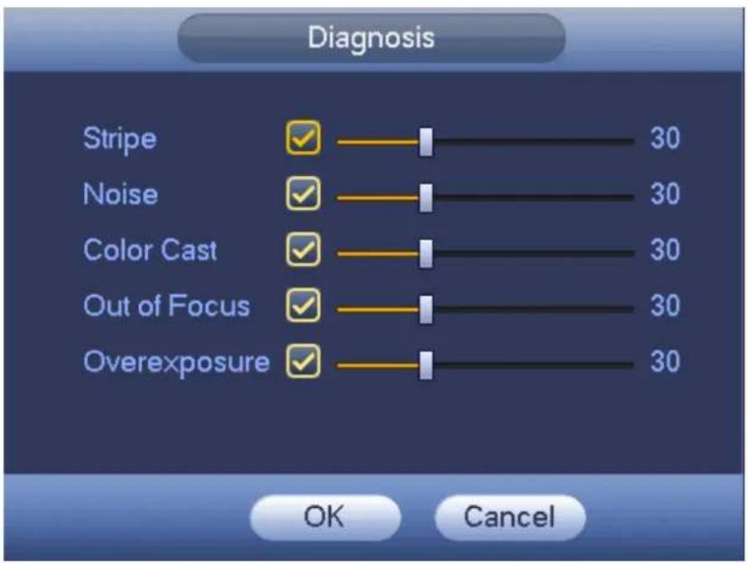
text_image
Diagnosis Stripe 30 Noise 30 Color Cast 30 Out of Focus 30 Overexposure 30 OK CancelFigure 4-104
Note
Video analysis alarm can trigger PTZ preset, tour, and pattern.
Please refer to motion detection for detailed information.
Alarm
Before operation, please make sure you have properly connected alarm devices such as buzzer. In the main menu, from Setting->Event->Alarm, you can see alarm setup interface.
For analog channel, the interface is shown as in Figure 4-107 and Figure 4-108
For HDUTC channel, there are three alarm types.
For digital channel, there are four alarm types. See Figure 4-107 to Figure 4-111.
- Local alarm: The alarm signal system detects from the alarm input port.
● Network alarm: It is the alarm signal from the network. - HDUTC: System can get the camera temperature, smoke, external alarm and set corresponding alarm activation operation.
- IPC external alarm: It is the on-off alarm signal from the front-end device and can activate the local DVR.
- IPC offline alarm: Once you select this item, system can generate an alarm when the front-end IPC disconnects with the local DVR. The alarm can activate record, PTZ, snap and etc. The alarm can last until the IPC and the DVR connection resumes.
Important
- If it is your first time to boot up the device, the disconnection status of the front-end network camera will not be regarded as offline. After one successfully connection, all the disconnection events will be regarded as IPC offline event.
- When IPC offline alarm occurs, the record and snapshot function of digital channel is null.
● Alarm in: Here is for you to select channel number.
● Type: normal open or normal close.
- PTZ activation: Here you can set PTZ movement when alarm occurs. Such as go to preset, tour& pattern when there is an alarm. Click “select” button, you can see an interface is shown as in Figure 4-112.
- Period: Click set button, you can see an interface is shown as in Figure 4-113. There are two ways for you to set periods. There are max 6 periods in one day. There are four record types: regular, motion detection (MD), Alarm, MD & alarm.
In Figure 4-113, Select icon of several dates, all checked items can be edited together.

text_image
Now the icon is shown as 📁 Click 🎨 to delete a record type from one period.In Figure 4-113. Click button after one date or a holiday, you can see an interface shown as in Figure 4-114. There are four record types: regular, motion detection (MD), Alarm, MD & alarm.
- Anti-dither: Here you can set anti-dither time. Here you can set anti-dither time. The value ranges from 5 to 600s. The anti-dither time refers to the alarm signal lasts time. It can be seen as the alarm signal activation stays such as the buzzer, tour, PTZ activation, snapshot, channel record. The stay time here does not include the latch time. During the alarm process, the alarm signal can begin an anti-dither time if system detects the local alarm again. The screen prompt, alarm upload, email and etc will not be activated. For example, if you set the anti-dither time as 10 second, you can see the each activation may last 10s if the local alarm is activated. During the process, if system detects another local alarm signal at the fifth second, the buzzer, tour, PTZ activation, snapshot, record channel will begin another 10s while the screen prompt, alarm upload, email will not be activated again. After 10s, if system detects another alarm signal, it can generate an alarm since the anti-dither time is out.
- Show message: System can pop up a message to alarm you in the local host screen if you enabled this function.
- Alarm upload: System can upload the alarm signal to the network (including alarm centre) if you enabled current function.
- Send email: System can send out email to alert you when alarm occurs.
- Record channel: you can select proper channel to record alarm video (Multiple choices). At the same time you need to set alarm record in schedule interface (Main Menu->Setting->Schedule) and select schedule record in manual record interface (Main Menu->Advance->Manual Record).
- Latch: Here is for you to set proper delay duration. Value ranges from 10 to 300 seconds. System automatically delays specified seconds in turning off alarm and activated output after external alarm cancelled.
- Tour: Here you can enable tour function when alarm occurs. System supports 1/8-window tour. Please note the tour setup here has higher priority than the tour setup you set in the Display interface. Once there two tours are both enabled, system can enable the alarm tour as you set here when an alarm occurred. If there is no alarm, system implements the tour setup in the Display interface.
- Snapshot: System can snapshot corresponding channel when an alarm occurs. Please note the activation snapshot has the higher priority than schedule snapshot. If you have enabled these two
types at the same time, system can activate the activation snapshot when alarm occurs, and otherwise system just operates the schedule snapshot.
- Video matrix Check the box here to enable this function. When an alarm occurs, SPOT OUT port displays device video output. It displays video (1-window tour) from alarm activation channel you select at the Record channel item.
- Log: Check the box here, system can record local alarm log.
- Buzzer: Highlight the icon to enable this function. The buzzer beeps when alarm occurs.
● Voice prompts: Check the box here to trigger audio broadcast function. You can select specified audio file here. System can play the audio file once the corresponding event occurs.
Please note, network alarm means the alarm signal from the TCP/IP. You can use NET SDK to activate network alarm. Comparing with the local alarm, there is no type, anti-dither, alarm upload function.
Please highlight icon ☐ to select the corresponding function. After setting all the setups please click save button, system goes back to the previous menu.

text_image
CAMERA NETWORK EVENT STORAGE SYSTEM VIDEO DETECT ALARM ABNORMALITY ALARM OUTPUT Local Net HDCVI IPC Ext IPC Offline Alarm In 1 Alarm Name Alarm In1 Enable ✓ Type NO Period Set Anti-dither 5 sec. ✓ Alarm Out 1 2 3 Latch 10 sec. ✓ Show Message ✓ Alarm Upload Send Email ✓ Record Channel 1 2 3 4 5 6 7 8 9 10 11 12 13 14 15 16 □ PTZ Activation Set Delay 10 sec. ✓ Tour 1 2 3 4 5 6 7 8 9 10 11 12 13 14 15 16 ✓ Snapshot 1 2 3 4 5 6 7 8 9 10 11 12 13 14 15 16 □ Video Matrix ✓ Buzzer ✓ Log □ Voice Prompts File Name None Default Copy Save Cancel ApplyFigure 4-105

text_image
CAMERA NETWORK EVENT STORAGE SYSTEM VIDEO DETECT ALARM ABNORMALITY ALARM OUTPUT Local Net HDCVI IPC Ext IPC Offline Alarm In 1 Alarm Name Alarm In1 Enable Period Set ✓ Alarm Out 1 2 3 Latch 10 sec. ✓ Show Message Send Email ✓ Record Channel 1 2 3 4 5 6 7 8 9 10 11 12 13 14 15 16 □ PTZ Activation Set Delay 10 sec. □ Tour 1 2 3 4 5 6 7 8 9 10 11 12 13 14 15 16 □ Snapshot 1 2 3 4 5 6 7 8 9 10 11 12 13 14 15 16 □ Video Matrix Buzzer ✓ Log □ Voice Prompts File Name None Default Copy Save Cancel ApplyFigure 4-106

text_image
SETTING CAMERA NETWORK EVENT STORAGE SYSTEM VIDEO DETECT ALARM ABNORMALITY ALARM OUTPUT Local Net HDCVI IPC Ext IPC Offline Alarm In 1 Alarm Name Alarm In1 Enable ✓ Period Set ✓ Alarm Out 1 2 3 Latch 10 sec. ✓ Show Message Send Email ✓ Record Channel 1 2 3 4 5 6 7 8 9 10 11 12 13 14 15 16 PTZ Activation Set Delay 10 sec. Tour 1 2 3 4 5 6 7 8 9 10 11 12 13 14 15 16 Snapshot 1 2 3 4 5 6 7 8 9 10 11 12 13 14 15 16 Video Matrix Buzzer ✓ Log Voice Prompts File Name None Default Copy Save Cancel ApplyFigure 4-107
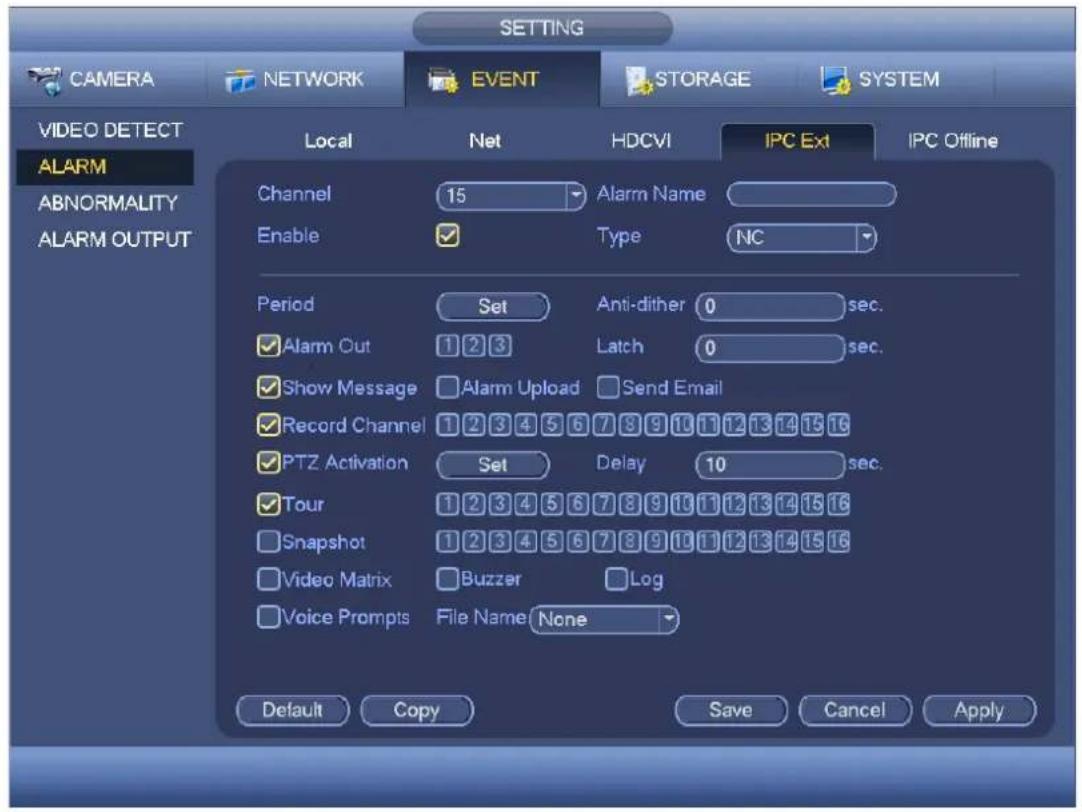
text_image
SETTING CAMERA NETWORK EVENT STORAGE SYSTEM VIDEO DETECT ALARM ABNORMALITY ALARM OUTPUT Local Net HDCVI IPC Ext IPC Offline Channel 15 Alarm Name Enable ✓ Type NC Period Set Anti-dither 0 sec. ✓ Alarm Out 1 2 3 Latch 0 sec. ✓ Show Message ✓ Alarm Upload Send Email ✓ Record Channel 1 2 3 4 5 6 7 8 9 10 11 12 13 14 15 16 ✓ PTZ Activation Set Delay 10 sec. ✓ Tour 1 2 3 4 5 6 7 8 9 10 11 12 13 14 15 16 ✓ Snapshot 1 2 3 4 5 6 7 8 9 10 11 12 13 14 15 16 ✓ Video Matrix ✓ Buzzer Log ✓ Voice Prompts File Name None Default Copy Save Cancel ApplyFigure 4-108
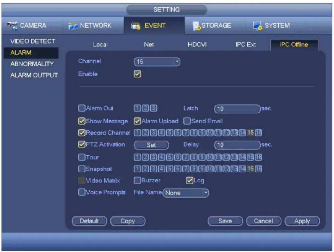
text_image
CAMERA NETWORK EVENT STORAGE SYSTEM VIDEO DETECT Local Net HDCVI IPC Ext IPC Offline ALARM Channel 15 Enable ✓ ✓ Alarm Out 1 2 3 Latch 10 sec. ✓ Show Message ✓ Alarm Upload Send Email ✓ Record Channel 1 2 3 4 5 6 7 8 9 10 11 12 13 14 15 16 ✓ PTZ Activation Set Delay 10 sec. ✓ Tour 1 2 3 4 5 6 7 8 9 10 11 12 13 14 15 16 ✓ Snapshot 1 2 3 4 5 6 7 8 9 10 11 12 13 14 15 16 ✓ Video Matrix ✓ Buzzer ✓ Log ✓ Voice Prompts File Name None Default Copy Save Cancel ApplyFigure 4-109
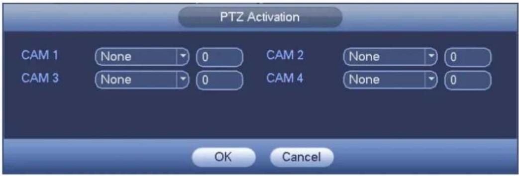
text_image
PTZ Activation CAM 1 None 0 CAM 2 None 0 CAM 3 None 0 CAM 4 None 0 OK CancelFigure 4-110
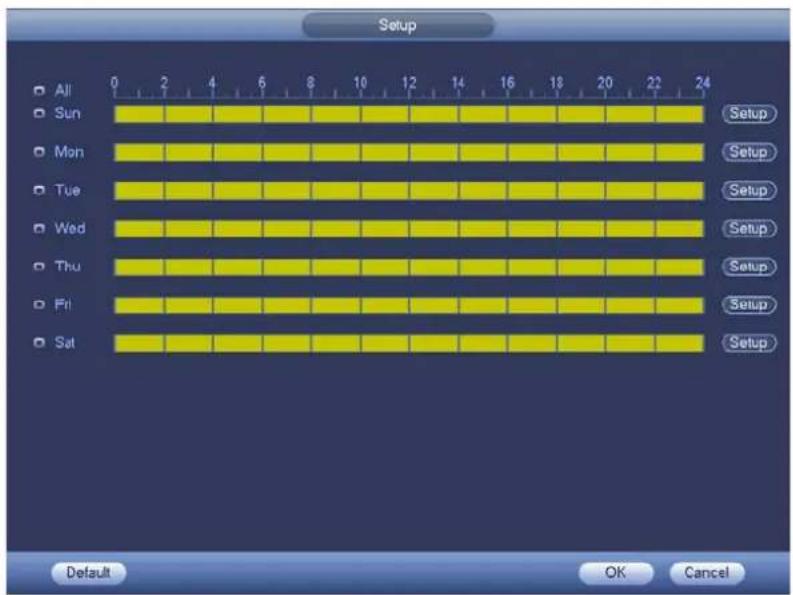
text_image
Setup All Sun Mon Tue Wed Thu Fri Sat 0 2 4 6 8 10 12 14 16 18 20 22 24 Setup Setup Setup Setup Setup Setup Setup Default OK CancelFigure 4-111

text_image
Time Period Current Date: Sun Period 1 00 :00 - 24 : 00 ✓ Period 2 00 :00 - 24 : 00 Period 3 00 :00 - 24 : 00 Period 4 00 :00 - 24 : 00 Period 5 00 :00 - 24 : 00 Period 6 00 :00 - 24 : 00 Copy All Sun Mon Tue Wed Thu Fri Sat SaveFigure 4-112
Abnormality
There are three types: HDD/Network/user.
✿ HDD: HDD error, no disk, no space. See Figure 4-115 and Figure 4-116.
Network: Disconnection, IP conflict, MAC conflict. See Figure 4-117.
User:Illegal login. See Figure 4-118.
● Alarm output: Please select alarm activation output port (multiple choices).
● Less than: System can alarm you when the HDD space is less than the threshold you set here (For HDD no space type only).
- Latch: Here you can set corresponding delaying time. The value ranges from 1s-300s. System automatically delays specified seconds in turning off alarm and activated output after external alarm cancelled.
● Show message: system can pop up the message in the local screen to alert you when alarm occurs.
- Alarm upload: System can upload the alarm signal to the network (including alarm centre) if you enabled current function. For disconnection event, IP conflict event and MAC conflict event, this function is null.
- Send email: System can send out email to alert you when alarm occurs.
● Buzzer: Highlight the icon to enable this function. The buzzer beeps when alarm occurs.
- Log: Check the box here, system can record HDD event log.
● Voice prompts: Check the box here to trigger audio broadcast function. You can select specified audio file here. System can play the audio file once the corresponding event occurs.
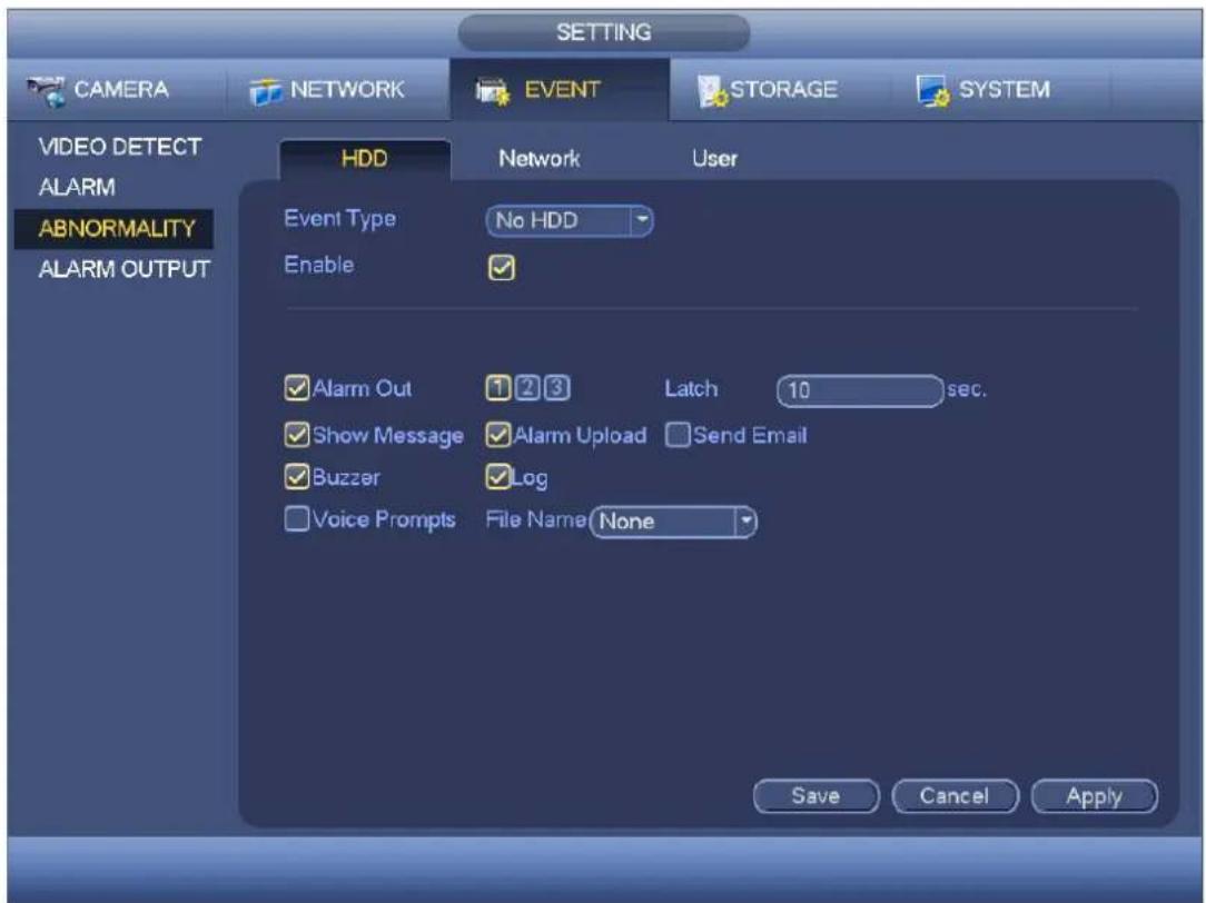
text_image
SETTING CAMERA NETWORK EVENT STORAGE SYSTEM VIDEO DETECT ALARM ABNORMALITY ALARM OUTPUT HDD Network User Event Type No HDD Enable ✓ Alarm Out 1 2 3 Latch 10 sec. ✓ Show Message ✓ Alarm Upload Send Email ✓ Buzzer ✓ Log ✓ Voice Prompts File Name None Save Cancel ApplyFigure 4-113

text_image
SETTING CAMERA NETWORK EVENT STORAGE SYSTEM VIDEO DETECT ALARM ABNORMALITY ALARM OUTPUT HDD Network User Event Type HDD No Spac Enable Less 20 % Alarm Out 1 2 3 4 5 6 Latch 10 sec. Show Message Alarm Upload Send Email Buzzer Log Voice Prompts File Name None Save Cancel ApplyFigure 4-114

text_image
SETTING CAMERA NETWORK EVENT STORAGE SYSTEM VIDEO DETECT ALARM ABNORMALITY ALARM OUTPUT HDD Network User Event Type Net Disconne Enable ✓ Alarm Out 1 2 3 Latch 10 sec. ✓ Show Message Send Email Record Channel 1 2 3 4 5 6 7 8 9 10 11 12 13 14 Buzzer Log Delay 10 sec. Voice Prompts File Name None Save Cancel ApplyFigure 4-115
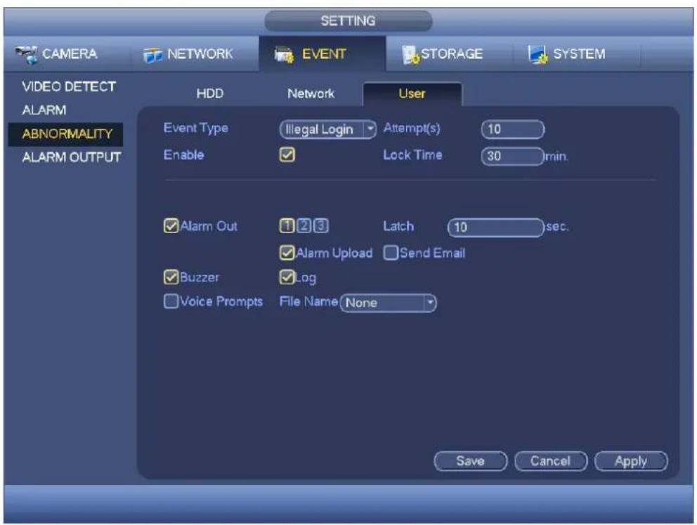
text_image
SETTING CAMERA NETWORK EVENT STORAGE SYSTEM VIDEO DETECT ALARM ABNORMALITY ALARM OUTPUT HDD Network User Event Type Illegal Login Attempt(s) 10 Enable Lock Time 30 min. Alarm Out 1 2 3 Latch 10 sec. Alarm Upload Send Email Buzzer Log Voice Prompts File Name None Save Cancel ApplyFigure 4-116
Alarm Output
Holis HD Series DVR User Manual 4, 8 & 16 Channel Models
Here is for you to set proper alarm output such as schedule, manual.
Please highlight icon ☐ to select the corresponding alarm output.
After all the setups please click OK button, system goes back to the previous menu. See Figure 4-119.
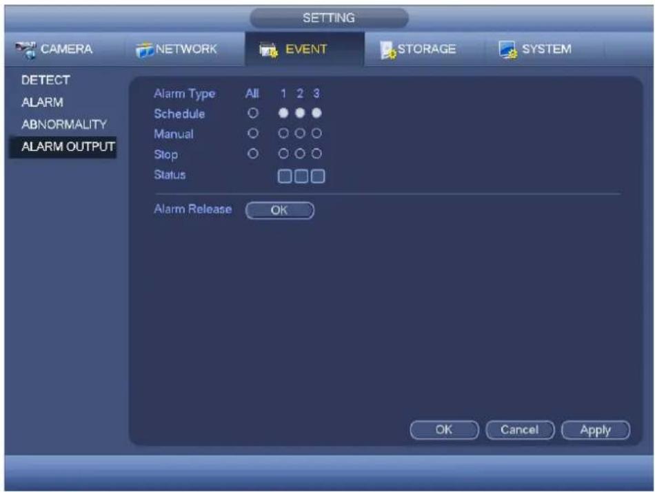
text_image
SETTING CAMERA NETWORK EVENT STORAGE SYSTEM DETECT ALARM ABNORMALITY ALARM OUTPUT Alarm Type All 1 2 3 Schedule ○ ● ● Manual ○ ○ ○ ○ Stop ○ ○ ○ ○ Status □□□ Alarm Release OK OK Cancel ApplyFigure 4-117
Storage
It is to set HDD management, storage parameters, set record plan and record control.
Schedule
It is for you to set record plan and snapshot plan.
Record
Note:
You need to have proper rights to implement the following operations. Please make sure the HDDs have been properly installed.
After the system booted up, it is in default 24-hour regular mode. You can set record type and time in schedule interface.
In the main menu, from Setting->Storage->Schedule, you can go to schedule menu. See Figure 4-123.
Please note you need to go to main menu->Setting->System->General->Holiday to set holiday date first, otherwise, there is no holiday setup item.
- Channel: Please select the channel number first. You can select "all" if you want to set for the whole channels.
✿ Sync connection icon. Select icon of several dates, all checked items can be e dited
together. Now the icon is shown as


✨: Click it to delete a record type from one period.
- Record Type: Please check the box to select corresponding record type. There are four types: Regular/MD (motion detect)/Alarm/MD&Alarm.
● Week day: There are eight options: ranges from Saturday to Sunday and all. - Holiday: It is to set holiday setup. Please note you need to go to the General interface (Main Menu->System->General) to add holiday first. Otherwise you can not see this item.
- Pre-record: System can pre-record the video before the event occurs into the file. The value ranges from 1 to 30 seconds depending on the bit stream.
- Redundancy: System supports redundancy backup function. You can highlight Redundancy button to activate this function. Please note, before enable this function, please set at least one HDD as redundant. (Main menu->Setting->Storage->HDD Manager). Please note this function is null if there is only one HDD.
- Period setup: Click button

after one date or a holiday, you can see an interface shown as in
Figure 4-124. There are four record types: regular, motion detection (MD), Alarm, MD & alarm.
Please following the steps listed below to draw the period manually.
Select a channel you want to set. See Figure 4-120.

text_image
Channel 1Figure 4-118
☆ Set record type. See Figure 4-121.

text_image
Regular MD ✓ Alarm MD&AlarmFigure 4-119
Please draw manually to set record period. There are six periods in one day. See Figure 4-122.
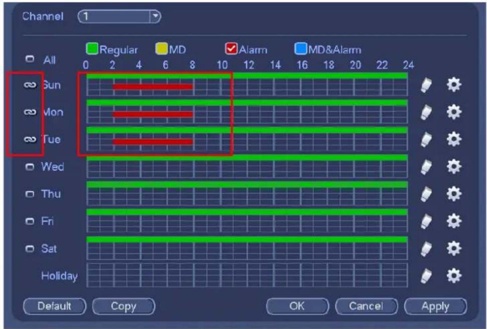
text_image
Channel 1 All Sun Mon Tue Wed Thu Fri Sat Holiday Regular MD Alarm MD&Alarm Default Copy OK Cancel ApplyFigure 4-120
Please highlight icon ☐ to select the corresponding function. After completing all the setups please click save button, system goes back to the previous menu.
There are color bars for your reference. Green color stands for regular recording, yellow color stands for motion detection and red color stands for alarm recording. The white means the MD and alarm record is valid. Once you have set to record when the MD and alarm occurs, system will not record neither motion detect occurs nor the alarm occurs.

text_image
SETTING CAMERA NETWORK EVENT STORAGE SYSTEM SCHEDULE HDD MANAGE RECORD Record Snapshot Channel 1 PreRecord 4 s Redundancy Regular MD Alarm MD&Alarm All 0 2 4 6 8 10 12 14 16 18 20 22 24 Sun Mon Tue Wed Thu Fri Sat Holiday Default Copy OK Cancel ApplyFigure 4-121
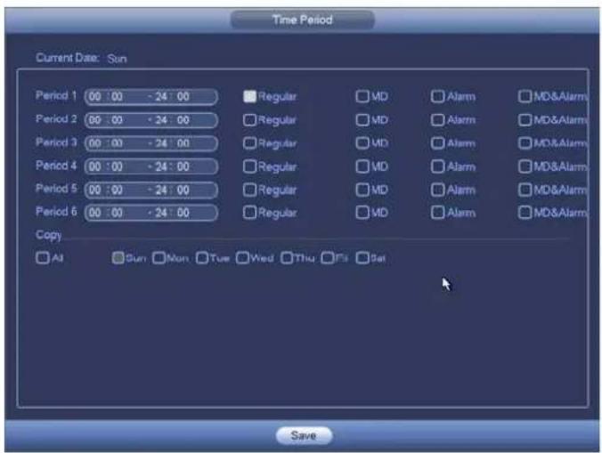
text_image
Time Period Current Date: Sun Period 1 00 : 00 - 24 : 00 Regular MD Alarm MD&Alarm Period 2 00 : 00 - 24 : 00 Regular MD Alarm MD&Alarm Period 3 00 : 00 - 24 : 00 Regular MD Alarm MD&Alarm Period 4 00 : 00 - 24 : 00 Regular MD Alarm MD&Alarm Period 5 00 : 00 - 24 : 00 Regular MD Alarm MD&Alarm Period 6 00 : 00 - 24 : 00 Regular MD Alarm MD&Alarm Copy All Sun Mon Tue Wed Thu F5 Sat SaveFigure 4-122
Quick Setup
Copy function allows you to copy one channel setup to another. After setting in channel 1, click Copy button, you can go to interface Figure 4-125. You can see current channel name is grey such as channel 1. Now you can select the channel you want to paste such as channel 5/6/7. If you want to save current setup of channel 1 to all channels, you can click the first box "ALL". Click the OK button to save current copy setup. Click the OK button in the Encode interface, the copy function succeeded.

text_image
Copy All 1 2 3 4 OK CancelFigure 4-123
Redundancy
Current series product does not support redundancy function.
Redundancy function allows you to memorize record file in several disks. When there is file damage occurred in one disk, there is a spare one in the other disk. You can use this function to maintain data reliability and safety.
- In the main menu, from Setting->Storage->Schedule, you can highlight redundancy button to enable this function.
- In the main menu, from Main menu->Setting->Storage->HDD Manager, you can set one or more disk(s) as redundant. You can select from the dropdown list. System auto overwrites old files once hard disk is full.
Please note only read/write disk or read-only disk can backup file and support file search function, so you need to set at least one read-write disk otherwise you can not record video.
Note
About redundancy setup:
- If current channel is not recording, current setup gets activated when the channel begin recording the next time.
- If current channel is recording now, current setup will get activated right away, the current file will be packet and form a file, then system begins recording as you have just set.
After all the setups please click save button, system goes back to the previous menu.
Playback or search in the redundant disk.
There are two ways for you to playback or search in the redundant disk.
- Set redundant disk(s) as read-only disk or read-write disk (Main menu->Setting->Storage->HDD Manager). System needs to reboot to get setup activated. Now you can search or playback file in redundant disk.
● Dismantle the disk and play it in another PC.
Snapshot
Schedule Snapshot
- On the preview interface, right click mouse and then select Manual->Record, or in the main menu, from Setting->Storage->Record, check the box to enable snapshot function of corresponding channels. See Figure 4-126.
- In main menu, from Setting->Camera->Encode->Snapshot interface, here you can input snapshot mode as regular, size, quality and frequency. See Figure 4-127.
- In main menu, from Setting->Camera->Encode->Schedule interface, please enable snapshot function. See Figure 4-128.
Please refer to the following figures for detailed information.
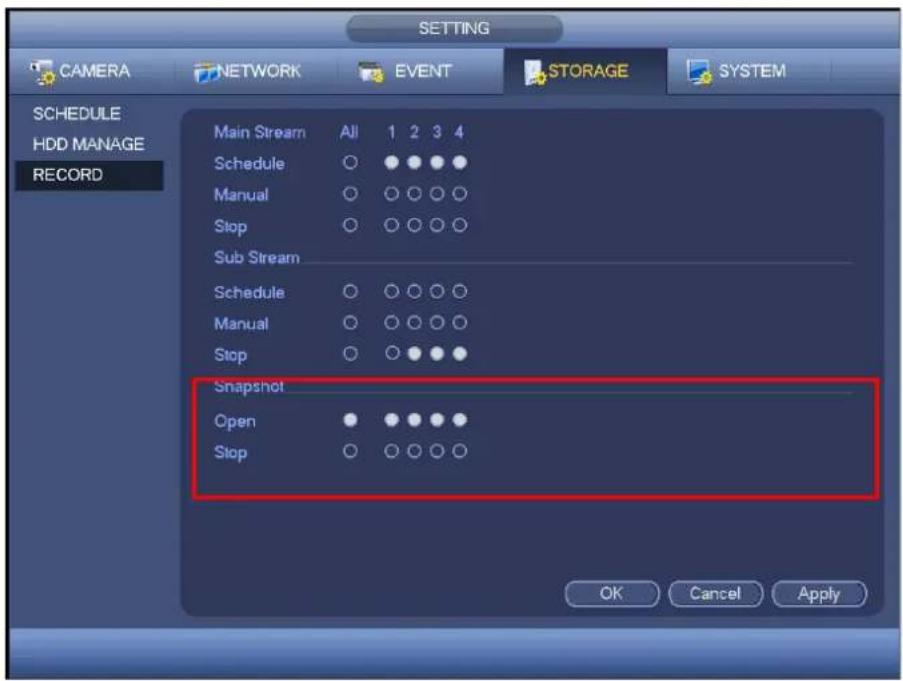
Please follow the steps listed below to enable the activation snapshot function. After you enabled this function, system can snapshot when the corresponding alarm occurred.
- In main menu, from Setting->Camera->Encode->Snapshot interface, here you can input snapshot mode as trigger, size, quality and frequency. See Figure 4-129.
- In main menu, from Setting->Event->Detect, please enable snapshot function for specified channels (Figure 4-130).

text_image
CAMERA NETWORK EVENT STORAGE SYSTEM IMAGE ENCODE CAM NAME CHANNEL TYPE Encode Snapshot Overlay Manual Snap 1 /Time Channel 1 Mode Trigger Image Size CIF Image Quality 4 Interval 1 S Default Copy OK Cancel ApplyFigure 4-127

text_image
SETTING CAMERA NETWORK EVENT STORAGE SYSTEM DETECT ABNORMALITY Motion Detect Video Loss Tampering Channel 1 Enable Region Setup Period Setup Anti-dither 5 s Show Message Alarm Upload Send Email Record Channel 2 3 4 PTZ Activation Setup Delay 10 s Tour 2 3 4 Snapshot 2 3 4 Buzzer Default Copy Test Save Cancel ApplyFigure 4-128
Priority
Please note the activation snapshot has the higher priority than schedule snapshot. If you have enabled these two types at the same time, system can activate the activation snapshot when alarm occurs, and otherwise system just operates the schedule snapshot.
Image FTP
In the main menu, from Setting->Network->FTP, you can set FTP server information. Please enable FTP function and then click save button. See Figure 4-131.
Please boot up corresponding FTP server.
Please enable schedule snapshot (Chapter 4.11.4.1.2.1) or activation snapshot (Chapter 4.11.4.1.2.2) first, now system can upload the image file to the FTP server.

text_image
NETWORK CAMERA NETWORK EVENT STORAGE SYSTEM TCP/IP CONNECTION WIFI 3G PPPoE DDNS P FILTER EMAIL FTP UPnP SNMP MULTICAST ALARM CENTRE REGISTER Enable Server IP 0 0 0 0 Port 21 User Name Password Anonymous Remote Directory File Length 0 M Image Upload Interval 2 sec. Channel 1 Weekday Thu Alarm Motion P Time Period 1 00:00 - 24:00 Time Period 2 00:00 - 24:00 Please input the corresponding information here, if you just upload the image FTP. Default Test OK CancelFigure 4-129
HDD Manager
Here is for you to view and implement hard disk management. See Figure 4-132.
You can see current HDD type, status, capacity and etc. The operation includes format HDD, and change HDD property (read and write/read-only/redundancy).
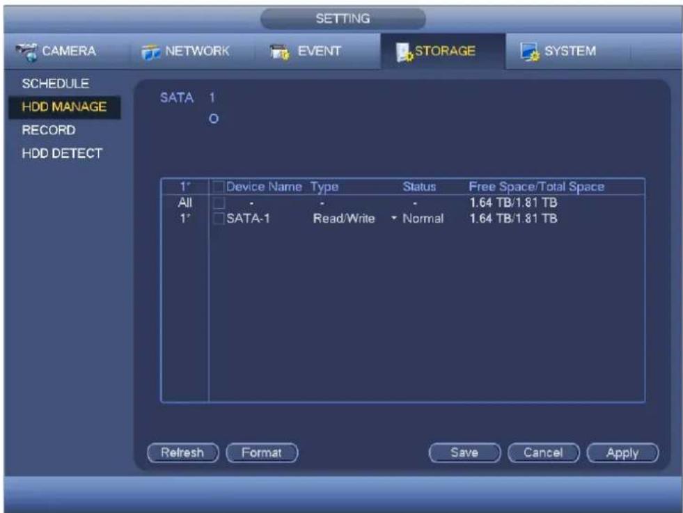
text_image
SETTING CAMERA NETWORK EVENT STORAGE SYSTEM SCHEDULE HDD MANAGE RECORD HDD DETECT SATA 1 0 1° Device Name Type Status Free Space/Total Space All - - - 1.64 TB/1.81 TB 1° SATA-1 Read/Write ▼ Normal 1.64 TB/1.81 TB Refresh Format Save Cancel ApplyFigure 4-130
Record
Record Control

Caution:
You need to have proper rights to implement the following operations. Please make sure the HDD has been properly installed.
There are three ways for you to go to manual record menu.
- Right click mouse and then select Manual->Record.
- In the main menu, from Setting->Storage->Record.
- In live viewing mode, click record button in the front panel or record button in the remote control.
System supports main stream and sub stream. There are three statuses: schedule/manual/stop. See Figure 4-133. Please highlight icon "O" to select corresponding channel.
● Manual: The highest priority. After manual setup, all selected channels will begin ordinary recording.
- Schedule: Channel records as you have set in recording setup (Main Menu->Setting->System->Schedule)
- Stop: Current channel stops recording.
- All: Check All button after the corresponding status to enable/disable all-channel schedule/manual record or enable/disable all channels to stop record.
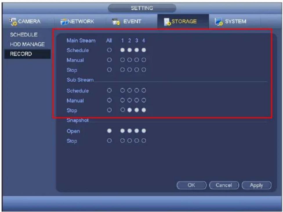
Check the corresponding box to enable/disable schedule snapshot function. See Figure 4-134.

You can check All button after the corresponding status to enable/disable all-channel snapshot function.
HDD Detect
The HDD detect function is to detect HDD current status so that you can clearly understand the HDD performance and replace the malfunction HDD.
There are two detect types:
- Quick detect is to detect via the universal system files. System can quickly complete the HDD scan. If you want to use this function, please make sure the HDD is in use now. If the HDD is removed from other device, please make sure the write-data once was full after it installed on current device.
- Global detect adopts Windows mode to scan. It may take a long time and may affect the HDD that is recording.
Manual Detect
The manual detect interface is shown as below. See Figure 4-135.
Please select detect type and HDD. Click start detect to begin. You can view the corresponding detect information. See Figure 4-136.
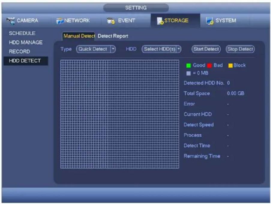
text_image
SETTING CAMERA NETWORK EVENT STORAGE SYSTEM SCHEDULE HDD MANAGE RECORD HDD DETECT Manual Detect Detect Report Type Quick Detect HDD Select HDD(s) Start Detect Stop Detect Good Bad Block = 0 MB Detected HDD No. 0 Total Space 0.00 GB Error - Current HDD - Detect Speed - Process - Detect Time - Remaining Time -Figure 4-133

text_image
SETTING CAMERA NETWORK EVENT STORAGE SYSTEM SCHEDULE HDD MANAGE RECORD HDD DETECT Manual Detect Detect Report Type Quick Detect HDD SATA - 1 Start Detect Stop Detect Good Bad Block = 103 MB Detected HDD No. 1 Total Space 232.89 GB Error 0 Current HDD 1 Detect Speed 10.00 GB/S Process 100.00 % Detect Time 00:00:01 Remaining Time 00:00:00Figure 4-134
Detect Report
After the detect operation, you can go to the detect report to view corresponding information.
The detect report interface is shown as below. See Figure 4-137.
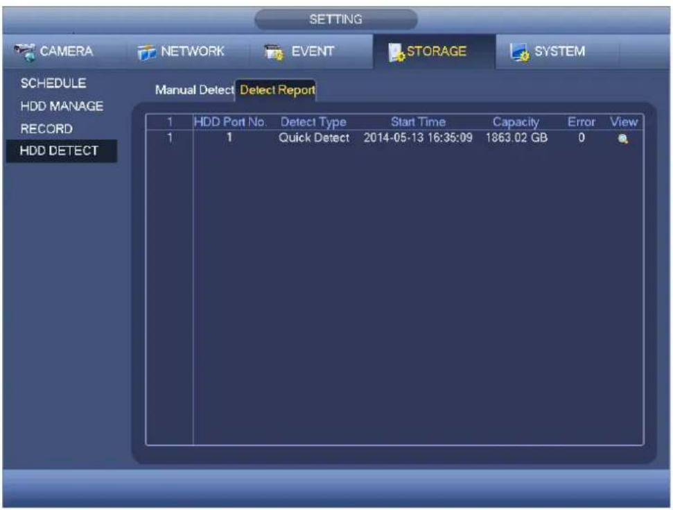
text_image
SETTING CAMERA NETWORK EVENT STORAGE SYSTEM SCHEDULE HDD MANAGE RECORD HDD DETECT Manual Detect Detect Report 1 HDD Port No. Detect Type Start Time Capacity Error View 1 1 Quick Detect 2014-05-13 16:35:09 1863.02 GB 0Figure 4-135
Click the item you can see the detailed information such as detect result. See Figure 4-138.

text_image
Details Type Quick Detect Good Bad Block = 103 MB Detected HDD No. 1 Total Space 232.89 GB Error 0 HDD Port No. 1Figure 4-136
System
General
Device
General setting includes the following items. See Figure 4-139.
● Device ID: Please input a corresponding device name here.
● Device No: Here you can set device number.
- Language: System supports various languages: Chinese (simplified), Chinese (Traditional), English, Italian, Japanese, French, Spanish (All languages listed here are optional. Slight difference maybe found in various series.)
● Video standard: There are two formats: NTSC and PAL.
- Video mode: It is to set max decode mode of the analog signal. There are two options: 960H/D1. Please note this item is only valid when all channels are analog modes only.
- HDD full: Here is for you to select working mode when hard disk is full. There are two options: stop recording or rewrite. If current working HDD is overwritten or the current HDD is full while the next HDD is no empty, then system stops recording, If the current HDD is full and then next HDD is not empty, then system overwrites the previous files.
- Pack duration: Here is for you to specify record duration. The value ranges from 1 to 120 minutes. Default value is 60 minutes.
● Real-time playback: It is to set playback time you can view in the preview interface. The value ranges from 5 to 60 minutes.
- Auto logout: Here is for you to set auto logout interval once login user remains inactive for a specified time. Value ranges from 0 to 60 minutes.
- IPC Time Sync: You can input an interval here to synchronize the DVR time and IPC time.
● Navigation bar: Check the box here, system displays the navigation bar on the interface.
- Startup wizard: Once you check the box here, system will go to the startup wizard directly when the system restarts the next time. Otherwise, it will go to the login interface.
- Mouse property: You can set double click speed via dragging the slide bard. You can Click Default button to restore default setup.
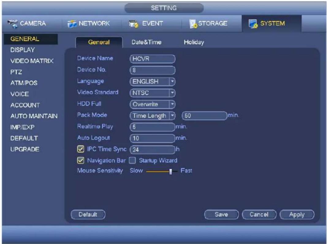
text_image
SETTING CAMERA NETWORK EVENT STORAGE SYSTEM GENERAL DISPLAY VIDEO MATRIX PT2 ATM/POS VOICE ACCOUNT AUTO MAINTAIN IMP/EXP DEFAULT UPGRADE General Date&Time Holiday Device Name HCVR Device No. 8 Language ENGLISH Video Standard NTSC HDD Full Overwrite Pack Mode Time Length 60 min. Realtime Play 5 min. Auto Logout 10 min. IPC Time Sync 24 h Navigation Bar Startup Wizard Mouse Sensitivity Slow Fast Default Save Cancel ApplyFigure 4-137
Date and Time
The interface is shown as in Figure 4-140.
- Date format: There are three types: YYYY-MM-DD: MM-DD-YYYY or DD-MM-YYYY.
● Date separator: There are three denotations to separate date: dot, beeline and solidus. - DST: Here you can set DST time and date. Here you can set start time and end time by setting corresponding week setup or by setting corresponding date setup.
● NTP: It is to set NTP server information.

text_image
SETTING CAMERA NETWORK EVENT STORAGE SYSTEM GENERAL DISPLAY VIDEO MATRIX PTZ ATM/POS VOICE ACCOUNT AUTO MAINTAIN IMP/EXP DEFAULT UPGRADE General Date&Time Holiday Date Format YYYY MM... Time Format 24-HOUR Date Separator - System Time 2016 - 01 - 14 15 : 56 : 39 GMT+08:00 Save DST DST Type Week Date Start Time 2000 - 01 - 01 00 : 00 End Time 2000 - 01 - 01 00 : 00 NTP Host IP time.windows.com Manual Update Port 123 Interval 60 min. Default Save Cancel ApplyFigure 4-138
Holiday
Holiday setup interface is shown as in Figure 4-141. Click Add new holiday button, you can input new holiday information. See Figure 4-142. Here you can set holiday name, repeat mode and start/end time.
Note
- When you enable Holiday settings and schedule setup at the same time, holiday setting has the priority. If the selected day is a holiday, then system records as you set in holiday setting. If it is not a holiday, system records as you set in Schedule interface. Please note
- Please note, there is no year setup on the holiday setup. For example, if you set 30th Oct, 2012 as a holiday, then the date of 30th Oct in each year will be set as a holiday.
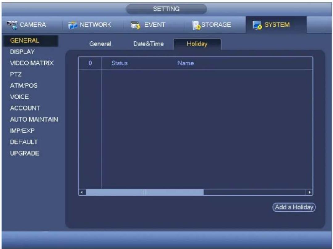
text_image
SETTING CAMERA NETWORK EVENT STORAGE SYSTEM GENERAL General Date&Time Holiday DISPLAY VIDEO MATRIX PTZ ATM/POS VOICE ACCOUNT AUTO MAINTAIN IMP/EXP DEFAULT UPGRADE 0 Status Name Add a HolidayFigure 4-139

text_image
Add New Holidays Holiday Name Repeat Mode ○ Once Only ● All-Year Holiday Range ● Date ○ Week Start Time 2013 - 10 - 18 End Time 2013 - 10 - 18 Add More Add CancelFigure 4-140
Display
It is to set display, TV adjust, tour, zero-channel encode, and preview favorites information.
Display
Display setup interface is shown as below. See Figure 4-143.
● Time display: You can select to display time or not when system is playback.
● Channel display: You can select to channel name or not when system is playback.
● Image original rate: Check the box here, the video can be displayed at its actual size.
- Transparency: Here is for you to adjust menu transparency. The higher the value is, the more transparent the menu is.
- Resolution: There are four options: 1920×1080, 1280×1024(default), 1280×720, 1024×768. Please note the system needs to reboot to activate current setup.
- Preview enhance: Check the box; it can optimize the video quality of the preview video.
● Video matrix: Check the box to enable video matrix function.
Please highlight icon ☐ to select the corresponding function.
After completing all the setups please click save button, system goes back to the previous menu.
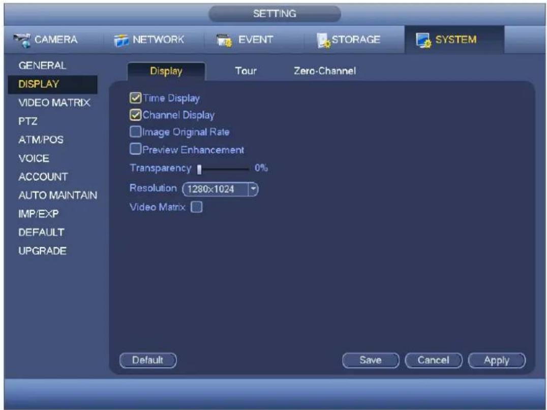
text_image
SETTING CAMERA NETWORK EVENT STORAGE SYSTEM GENERAL DISPLAY VIDEO MATRIX PTZ ATM/POS VOICE ACCOUNT AUTO MAINTAIN IMP/EXP DEFAULT UPGRADE Display Tour Zero-Channel ✓ Time Display ✓ Channel Display ☐ Image Original Rate ☐ Preview Enhancement Transparency 0% Resolution 1280x1024 Video Matrix Default Save Cancel ApplyFigure 4-141
Tour
Here you can activate tour function. Click Setup button, you can see an interface shown as in Figure 4-144
● Enable tour: Highlight box here to enable this function.
- Interval: System supports 1/8-window tour. Input proper interval value here. The value ranges from 5-120 seconds. It is for schedule tour/alarm/motion detect tour.
- Split: You can select window split mode from the dropdown list.
- Channel group: It is to display all channel groups on current split mode. You can edit and delete a channel group here. Double click an item in the list; you can edit its channel group setup. Right now system max supports 32.
- Add: Under specified window split mode, click it to add channel group.
- Delete: Click it to remove selected channel group.
- Move up: Click it to move current selected channel up.
- Move down: Click it to move current selected channel down.
● Default: Click it to restore default setup.
Tips:
- Use mouse or Shift button to switch 🔒 and 🔒 button to enable /disable tour. 🔒 means the tour funciton is enabled and 🔒 meas tour funciton is disabled.
- On the navigation bar, click or to enable/disable tour function.

text_image
SETTING CAMERA NETWORK EVENT STORAGE SYSTEM GENERAL DISPLAY VIDEO MATRIX PTZ ATM/POS VOICE ACCOUNT AUTO MAINTAIN IMP/EXP DEFAULT UPGRADE Display Tour Zero-Channel Enable ✓ Interval 5 sec. Video Detect View 1 Alarm View 1 Window Split View 1 8 Channel Group 1 ✓ 1 2 ✓ 2 3 ✓ 3 4 ✓ 4 5 ✓ 5 6 ✓ 6 7 ✓ 7 8 ✓ 8 Add Modify Delete Move up Move down Default Save Cancel ApplyFigure 4-142
Zero-channel Encoding
Click zero-channel encoding button, you can go to the following interface. See Figure 4-145. Here you can enable and set zero-channel encoding function so that you can view several video sources at one channel.
- Enable: This function is disabled by default. Check the box here to enable this function so that you can control the zero-channel encoding function at the WEB.
- Compression: System default setup is H.264. You can set according to device capability. - Resolution: The resolution value may vary due to different device capabilities. Please select from the dropdown list.
- Frame rate: The frame rate value may vary due to different device capabilities. Please select from the dropdown list.
- Bit Rate: The bit rate value may vary due to different device capabilities and frame rate setups. Please select from the dropdown list.
- Save: Click the Save button to save current setup. If this function is disabled, you can not operate zero-channel encoding function at the WEB, the video is black or null even you operate when the function is disabled. After you enabled this function, login the Web and you can select zero-channel
encoding mode at the right corner of the interface. Select a mode; you can view the local preview video.
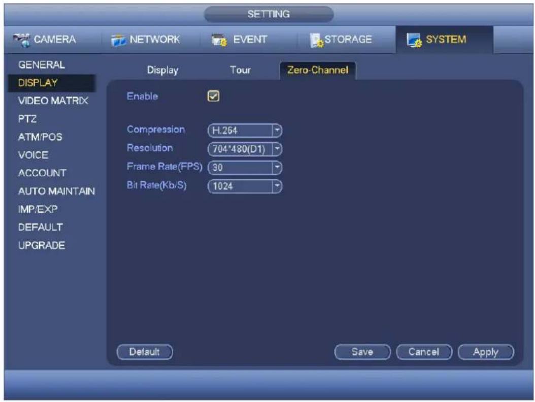
text_image
CAMERA NETWORK EVENT STORAGE SYSTEM GENERAL DISPLAY VIDEO MATRIX PTZ ATM/POS VOICE ACCOUNT AUTO MAINTAIN IMP/EXP DEFAULT UPGRADE Display Tour Zero-Channel Enable Compression H.264 Resolution 704*480(D1) Frame Rate(FPS) 30 Bit Rate(Kb/S) 1024 Default Save Cancel ApplyFigure 4-143
Video Matrix
Here you can set matrix output channel and its interval. You can set HDMI2 port tour and its interval See Figure 4-146.
● Enable tour: Check the box here to enable this function.
- Interval: Input proper interval value here.
● Resolution: The resolution of the tour window. Please note this function is for HDMI only.
- Split: You can select window split mode from the dropdown list. For BNC, it supports 1-split mode only. For HDMI, it supports 1/4/9/16-split mode. Some series product support 24/36-split. Please refer to the actual product.
- Add: Under specified window split mode, click it to add channel group. See Figure 4-147.
- Modify: Double click a channel or select a channel and then click Modify button, you can change current channel setup. See Figure 4-148.
- Delete: Click it to remove selected channel group.
- Move up: Click it to move current selected channel up.
- Move down: Click it to move current selected channel down.
● Default: Click it to restore default setup.

text_image
SETTING CAMERA NETWORK EVENT STORAGE SYSTEM GENERAL DISPLAY VIDEO MATRIX PTZ ATM/POS VOICE ACCOUNT AUTO MAINTAIN IMP/EXP DEFAULT UPGRADE Enable Interval 5 sec. Resolution 1280x720 Window Split View 1 14 Channel Group 1 1 2 2 3 3 4 4 5 5 6 6 7 7 8 8 9 9 10 10 11 11 12 12 Add Modify Delete Move up Move down Default Save Cancel ApplyFigure 4-144

text_image
Add Group 1 2 3 4 5 6 7 8 9 10 11 12 13 14 15 16 Group Order: OK CancelFigure 4-145
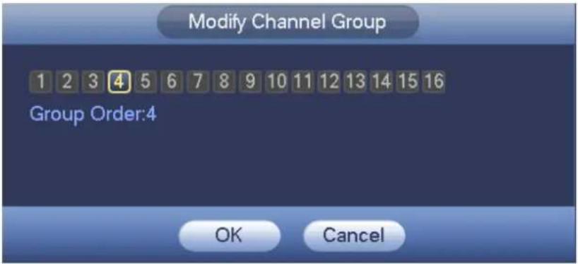
text_image
Modify Channel Group 1 2 3 4 5 6 7 8 9 10 11 12 13 14 15 16 Group Order:4 OK CancelFigure 4-146
PTZ
The pan/tilt/zoom setup includes the following items. Please select channel first. See Figure 4-149.
- PTZ type: There are two options: local/remote. Please select remote if you are connecting to the network PTZ. See Figure 4-150.
- Control mode: You can select control mode from the dropdown list. There are two options: Serial/HDUTC. For Holis series product, please select HDUTC. The control signal is sent to the PTZ via the coaxial cable. For the serial mode, the control signal is sent to the PTZ via the RS485 port.
- Protocol: Please select corresponding protocols such as HD-UTC.
- Address: input corresponding PTZ address.
● Baud rate: Select baud rate.
● Data bit: Select data bit. - Stop bit: Select stop bit.
● Parity: There are three choices: none/odd/even.
After completed all the setups please click save button, system goes back to the previous menu.

text_image
CAMERA NETWORK EVENT STORAGE SYSTEM GENERAL DISPLAY VIDEO MATRIX PAN/TILT/ZOOM TEXT OVERLAY VOICE ACCOUNT AUTO MAINTAIN IMP/EXP DEFAULT UPGRADE Channel 1 Control Mode HDUTC Protocol HD-UTC Address 1 Baudrate 9600 Data Bits 8 Stop Bits 1 Parity None Default Copy Save Cancel ApplyFigure 4-147
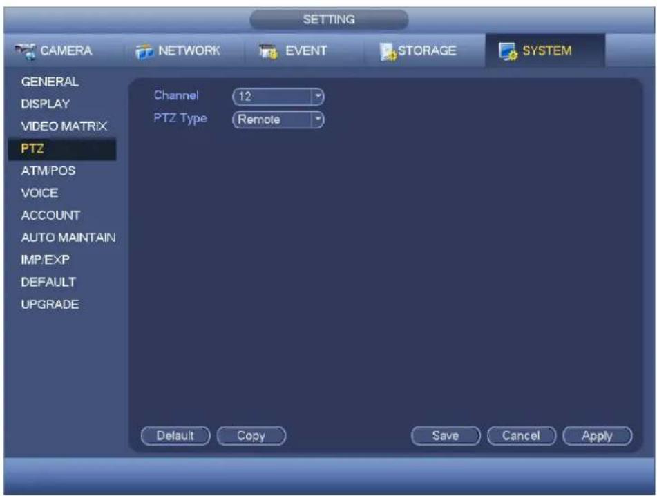
text_image
SETTING CAMERA NETWORK EVENT STORAGE SYSTEM GENERAL DISPLAY VIDEO MATRIX PTZ ATM/POS VOICE ACCOUNT AUTO MAINTAIN IMP/EXP DEFAULT UPGRADE Channel 12 PTZ Type Remote Default Copy Save Cancel ApplyFigure 4-148
ATM/POS
The ATM/POS function is for financial areas. It includes Sniffer, information analysis and title overlay function. The Sniffer mode is network.
The network type interface is shown as below. See Figure 4-151.
Here we take the ATM/POS protocol to continue.
There are two types: with or without the protocol according to client's requirements.
With the protocol
For ATM/POS with the protocol, you just need to set the source IP, destination IP (sometimes you need to input corresponding port number).

text_image
SETTING CAMERA NETWORK EVENT STORAGE SYSTEM GENERAL DISPLAY VIDEO MATRIX PTZ ATM/POS VOICE ACCOUNT AUTO MAINTAIN IMP/EXP DEFAULT UPGRADE Net Protocol ATM/POS Current Sniffer Mode is NET Overlay Mode Preview Record Overlay Position Top Left Data Group Data Group1 Source IP 0 . 0 . 0 . 0 Port 0 Destination IP 0 . 0 . 0 . 0 Port 0 Record Channel 1 2 3 4 5 6 7 8 StartPosition Length Key Frame ID1 1 0 Data Frame ID2 1 0 Data Frame ID3 1 0 Data Frame ID4 1 0 Data Frame ID5 1 0 Data Frame ID6 1 0 Data Save Cancel ApplyFigure 4-149
Without the protocol
For the ATM/POS without the protocol, the interface is shown as in Figure 4-152.
Source IP refers to host IP address that sends out information (usually it is the device host.)
Destination IP refers to other systems that receive information.
Usually you do not need to set source port and target port.
There are total four groups IP. The record channel applies to one group (optional) only.
Six frame ID groups verification can guarantee information validity and legal.
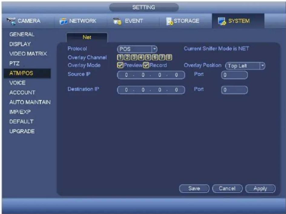
text_image
SETTING CAMERA NETWORK EVENT STORAGE SYSTEM GENERAL DISPLAY VIDEO MATRIX PTZ ATM/POS VOICE ACCOUNT AUTO MAINTAIN IMP/EXP DEFAULT UPGRADE Net Protocol POS Current Snifter Mode is NET Overlay Channel 1 2 3 4 5 6 7 8 Overlay Mode Preview Record Overlay Position Top Left Source IP 0 . 0 . 0 . 0 Port 0 Destination IP 0 . 0 . 0 . 0 Port 0 Save Cancel ApplyFigure 4-150
Voice
The audio function is to manage audio files and set schedule play function. It is to realize audio broadcast activation function.
File List
Here you can add audio file, listen to the audio file, or rename/delete audio file. Here you can also set audio volume. See Figure 4-153.

text_image
SETTING CAMERA NETWORK EVENT STORAGE SYSTEM GENERAL DISPLAY VIDEO MATRIX RS232 PTZ ATM/POS VOICE ACCOUNT AUTO MAINTAIN IMP/EXP DEFAULT UPGRADE File Manage Schedule 1 File Name Size Play Rename Delete 1 When You Know.mp3 3.77 MB VOICE : USB Mode Volume AddFigure 4-151
Click Add button, you can add audio file and import the audio file via the USB device. See Figure 4-154.
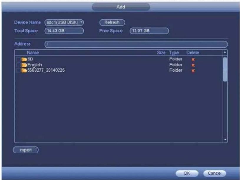
text_image
Add Device Name sdc1(USB DISK) Refresh Total Space 14.43 GB Free Space 12.07 GB Address / Name Size Type Delete SD Folder × English Folder × 5563277_20140225 Folder × Import OK CancelFigure 4-152
The audio file can be saved on the HDD or on the USB device.
- In Figure 4-153, when it is HDD mode, the newly added audio file can be saved on the HDD automatically. You do not need to connect to the USB device if you want to use it the next time.
- In Figure 4-153, when it is USB mode, after you imported, you need to connect the USB device all the time; otherwise, the audio link function may fail. So, if you want to use the audio trigger function, please make sure the audio file is on the UBS device and the USB device has connected to the DVR before the DVR boots up. You need to make sure the USB device connection is always there if you want to manage and use the audio file function.
- If there is a USB device (containing the audio file) and the HDD (containing the audio file) at the same time, the HDD mode has higher priority. That is to say, DVR uses the audio file from the HDD.
Account
Here is for you to implement account management. See Figure 4-155. Here you can:
- Add new user
- Modify user
- Add group
- Modify group
- Modify password.
For account management please note:
- For the user account name and the user group, the string max length is 6-byte. The backspace in front of or at the back of the string is invalid. There can be backspace in the middle. The string includes the valid character, letter, number, underline, subtraction sign, and dot.
-
The default user amount is 64 and the default group amount is 20. System account adopts two-level management: group and user. No limit to group or user amount.
● For group or user management, there are two levels: admin and user. -
The user name and group name can consist of eight bytes. One name can only be used once. There are three default users: admin/888888 and hidden user "default".
- Hidden user "default" is for system interior use only and can not be deleted. When there is no login user, hidden user "default" automatically login. You can set some rights such as monitor for this user so that you can view some channel view without login.
● One user should belong to one group. User right can not exceed group right. - About reusable function: this function allows multiple users use the same account to login.
- About user account and MAC. When you add a new user, you can input the MAC address of current user. Only the user of the same MAC address can access the device remotely.(MAC address is for the device of the same LAN.) If you leave MAC address item in blank when you add a new user, the user of any MAC address can access the device remotely. You can set or change MAC address when you add or modify a user. The MAC address function is also valid for PSS login. Please note current function does not support IPV6.
After all the setups please click save button, system goes back to the previous menu.
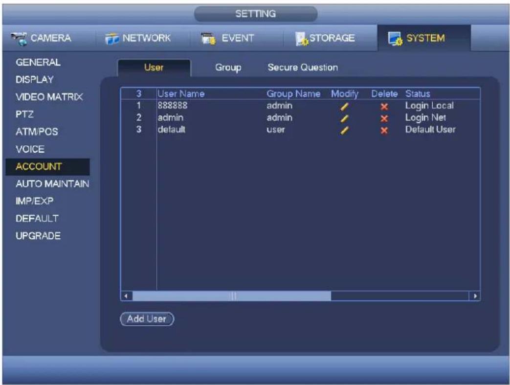
text_image
SETTING CAMERA NETWORK EVENT STORAGE SYSTEM GENERAL DISPLAY VIDEO MATRIX PTZ ATM/POS VOICE ACCOUNT AUTO MAINTAIN IMP/EXP DEFAULT UPGRADE User Group Secure Question 3 User Name Group Name Modify Delete Status 1 888888 admin ✓ × Login Local 2 admin admin ✓ × Login Net 3 default user ✓ × Default User Add UserFigure 4-153
Add User
Click modify user button in Figure 4-155, the interface is shown as in Figure 4-156.
Please input the user name, password, select the group it belongs to from the dropdown list.
Then you can check the corresponding rights for current user.
For convenient user management, usually we recommend the general user right is lower than the admin account.
- Username: admin. Password: admin. (administrator, local and network)
- Username: default. Password: default (hidden user). Hidden user "default" is for system interior use only and can not be deleted. When there is no login user, hidden user "default" automatically login. You can set some rights such as monitor for this user so that you can view some channels without login.
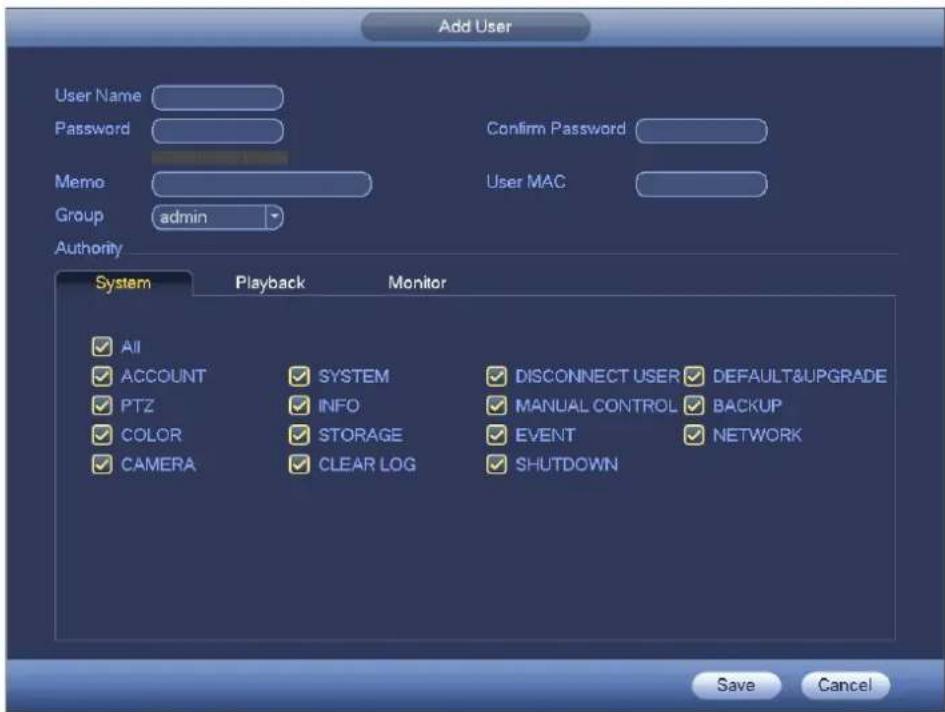
text_image
Add User User Name Password Confirm Password Memo User MAC Group admin Authority System Playback Monitor ✓ All ✓ ACCOUNT ✓ SYSTEM ✓ DISCONNECT USER ✓ DEFAULT&UPGRADE ✓ PTZ ✓ INFO ✓ MANUAL CONTROL ✓ BACKUP ✓ COLOR ✓ STORAGE ✓ EVENT ✓ NETWORK ✓ CAMERA ✓ CLEAR LOG ✓ SHUTDOWN Save CancelFigure 4-154
When you create a new user, you can input the corresponding MAC address of current user. If you leave this item in blank, any MAC address user can share this user account to login. Please note system needs to check the validity of MAC. Only the 12-digit 0-f format address can pass the validity verification. System only saves small character even you input capitalized one. You can see the corresponding prompt if there is any illegal input.
Click the Set button after the period, you can set valid period to use current account. See Figure 4-157.
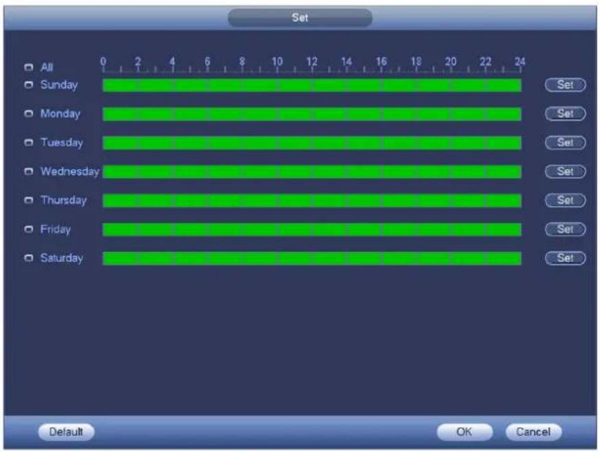
text_image
Set All Sunday Monday Tuesday Wednesday Thursday Friday Saturday 0 2 4 6 8 10 12 14 16 18 20 22 24 Set Set Set Set Set Set Set Default OK CancelFigure 4-155
Click Set button, you can set six periods in one day. See Figure 4-158.
Check the box after the period, you can enable current setup.

text_image
Period Current Date: Sunday Period 1 00 : 00 - 24 : 00 ✓ Period 2 00 : 00 - 24 : 00 Period 3 00 : 00 - 24 : 00 Period 4 00 : 00 - 24 : 00 Period 5 00 : 00 - 24 : 00 Period 6 00 : 00 - 24 : 00 Copy All Sunday Monday Tuesday Wednesday Thursday Friday Saturday OKFigure 4-156
Modify user
Click 📄, you can go to the following interface to change user information. See Figure 4-159.
For admin, and default (hidden user), you can not change period setup.

text_image
Modify User User Name default Modify Password Old Password New Password Confirm Password User MAC User Name Group user Memo default account Authority System Playback Monitor All ACCOUNT SYSTEM DISCONNECT USER DEFAULT&UPGRADE PTZ INFO MANUAL CONTROL BACKUP COLOR STORAGE EVENT NETWORK CAMERA CLEAR LOG SHUTDOWN Save CancelFigure 4-157
Change Password
In Figure 4-159, check the Modify password box, you can change password. Please input old password, and then input new password twice to confirm.
The password can contain 32-byte and the space at the begin or at the end of the password are null. It can contain in the middle of the password. For the user of account right, it can change the password of other users.
Add/Modify Group
In Figure 4-155, click Group button, you can see the following interface. See Figure 4-160.

text_image
SETTING CAMERA NETWORK EVENT STORAGE SYSTEM GENERAL DISPLAY VIDEO MATRIX PTZ ATM/POS VOICE ACCOUNT AUTO MAINTAIN IMP/EXP DEFAULT UPGRADE User Group Secure Question 2 Group Name Modify Delete Memo 1 admin / * administrator group 2 user / * user group Add GroupFigure 4-158
Click add group button in Figure 4-160, the interface is shown as below. See Figure 4-161.
Here you can input group name and then input some memo information if necessary.
There are total 98 rights such as control panel, shut down, real-time monitor, playback, record, record file backup, PTZ, user account, system information view, alarm input/output setup, system setup, log view, clear log, upgrade system, control device and etc.

text_image
Add Group Group Name Memo Authority System Playback Monitor All SYSTEM DISCONNECT USER DEFAULT&UPGRADE ACCOUNT INFO MANUAL CONTROL BACKUP PTZ STORAGE EVENT NETWORK COLOR CLEAR LOG SHUTDOWN CAMERA Save CancelFigure 4-159
Auto Maintain
Here you can set auto-reboot time and auto-delete old files setup. You can set to delete the files for the specified days. See Figure 4-162.
You can select proper setup from dropdown list.
After all the setups please click save button, system goes back to the previous menu.
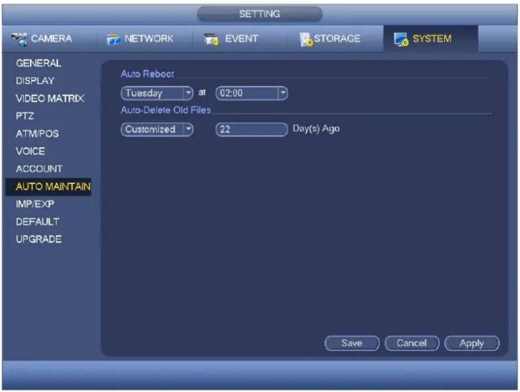
text_image
CAMERA NETWORK EVENT STORAGE SYSTEM GENERAL DISPLAY VIDEO MATRIX PTZ ATM/POS VOICE ACCOUNT AUTO MAINTAIN IMP/EXP DEFAULT UPGRADE Auto Reboot Tuesday at 02:00 Auto-Delete Old Files Customized 22 Day(s) Ago Save Cancel ApplyFigure 4-160
Config Backup
The configuration file backup interface is shown as below. See Figure 4-163.
This function allows you to import/export system configuration. You can use this function when there are several devices need the same setup.
- Export: Please connect the peripheral device first and then go to the following interface. Click Export button, you can see there is a corresponding "Config_Time" folder. Double click the folder, you can view some backup files.
- Import: Here you can import the configuration files from the peripheral device to current device. You need to select a folder first. You can see a dialogue box asking you to select a folder if you are selecting a file. System pops up a dialogue box if there is no configuration file under current folder. After successfully import, system needs to reboot to activate new setup.
- Format: Click Format button, system pops up a dialogue box for you to confirm current operation. System begins format process after you click the OK button.
Note:
- System can not open config backup interface again if there is backup operation in the process.
- System refreshes device when you go to the config backup every time and set current directory as the root directory of the peripheral device.
- If you go to the configuration backup interface first and then insert the peripheral device, please click Refresh button to view the newly added device.

text_image
CAMERA NETWORK EVENT STORAGE SYSTEM GENERAL DISPLAY VIDEO MATRIX PTZ ATM/POS VOICE ACCOUNT AUTO MAINTAIN IMP/EXP DEFAULT UPGRADE Device Name sdc1(USB DISK) Refresh Total Space 14.43 GB Free Space 4.67 GB Address / Name Size Type Delete English Folder New Folder Format Import ExportFigure 4-161
Default
Click default icon, system pops up a dialogue box. You can highlight ☐ to restore default factory setup. See Figure 4-164.
- Camera
- Network
- Event
- Storage
- System
Please highlight icon ☐ to select the corresponding function. Click factory default button, you can restore factory default setup.
After all the setups please click save button, system goes back to the previous menu.
Note:
System menu color, language, time display mode, video format, IP address, user account will not maintain previous setup after default operation!
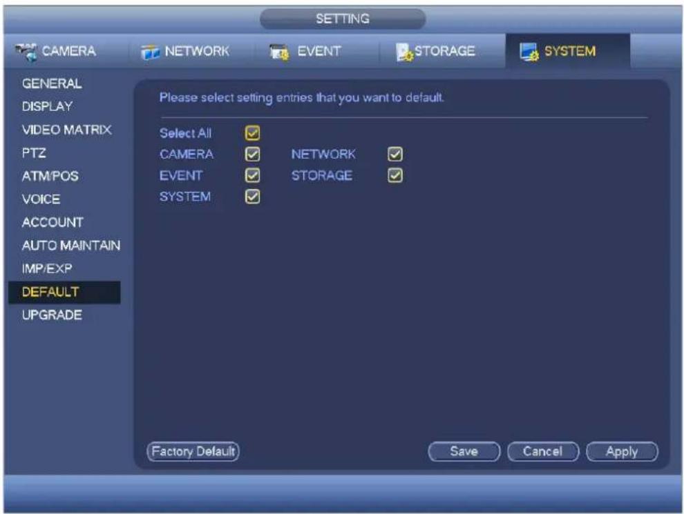
text_image
SETTING CAMERA NETWORK EVENT STORAGE SYSTEM GENERAL DISPLAY VIDEO MATRIX PTZ ATM/POS VOICE ACCOUNT AUTO MAINTAIN IMP/EXP DEFAULT UPGRADE Please select setting entries that you want to default. Select All CAMERA EVENT SYSTEM NETWORK STORAGE Factory Default Save Cancel ApplyFigure 4-162
Update
Here is for you to view hardware features, software version, built date, release SN information and etc. You can also update system here. See Figure 4-165.
- Start: Please insert the USB device that have the update file to the device and then click the Start button to begin the update.
Important
Please make sure the upgrade file name shall be update.bin.
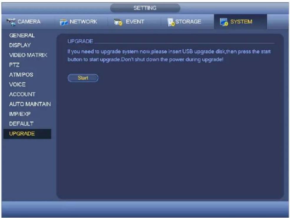
text_image
SETTING CAMERA NETWORK EVENT STORAGE SYSTEM GENERAL DISPLAY VIDEO MATRIX PTZ ATM/POS VOICE ACCOUNT AUTO MAINTAIN IMP/EXP DEFAULT UPGRADE UPGRADE If you need to upgrade system now, please insert USB upgrade disk, then press the start button to start upgrade. Don't shut down the power during upgrade! StartFigure 4-163
Slightly difference may be found in the interface due to different series.
Network Connection
Before web client operation, please check the following items:
● Network connection is right
- DVR and PC network setup is right. Please refer to network setup(main menu->Setting->Network)
- Use order ping ***.***.***.***(* DVR IP address) to check connection is OK or not. Usually the return TTL value should be less than 255.
- Current series product supports various browsers such as Safari, fire fox browser, Google browser. Device supports multiple-channel monitor, PTZ control, DVR parameter setup on the Apple PC.
Login
Open IE and input DVR address in the address column. For example, if your DVR IP is 10.10.3.16, then please input http://10.10.3.16 in IE address column.
System pops up warning information to ask you whether install controls or not. Please click Install button. See Figure 5-1.
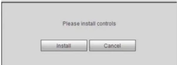
text_image
Please install controls Install CancelFigure 5-1
After installation, the interface is shown as below. See Figure 5-2.
Please input your user name and password.
Default factory name is admin and password is admin.
Note: For security reasons, please modify your password after you first login.
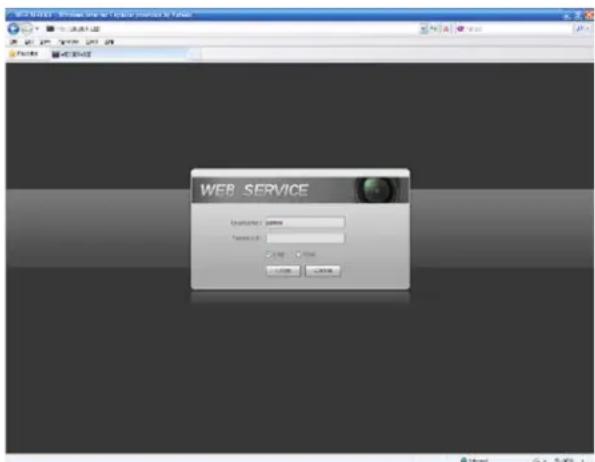
text_image
WEB SERVICE Login Account: 100000 Password: 2.0000 Access: 1.0000 Download: 5.0000Figure 5-2
LAN Mode
For the LAN mode, after you logged in, you can see the main window. See Figure 5-3.
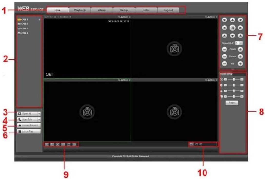
text_image
WER SERVICE Live Playback Alarm Setup Info Logout 1 CAM 1 CAM 2 CAM 3 CAM 4 2013-11-24 IC 20:56 CAM 1 Image Setup 7 Speed1-6: 6 Room Focus No 8 Open All Start Talk Present Recall Local Play 9 10 Copyright 2013 All Rights DessevedFigure 5-3
This main window can be divided into the following sections.
● Section 1: there are six function buttons: Live, playback, setup, info, alarm, and logout.
- Section 2: There are channel number and one button: Start all. Start all button is to enable/disable all-channel real-time monitor. Click it the button becomes yellow. See Figure 5-4.

Figure 5-4
Please refer to Figure 5-5 for main stream and extra stream switch information.
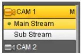
text_image
CAM 1 M • Main Stream Sub Stream CAM 2Figure 5-5
- Section 3: Start dialogue button.
You can click this button to enable audio talk. Click 【▼】 to select bidirectional talk mode. There are four options: DEFAULT, G711a, G711u and PCM. After you enable the bidirectional talk, the Start talk button becomes End Talk button and it becomes yellow. See Figure 5-6.
Note:
Note:
If audio input port from the device to the client-end is using the first channel audio input port. During the bidirectional talk process, system will not encode the audio data from the 1-channel.

text_image
Start Talk DEFAULT G711a G711u PCM End TalkFigure 5-6
- Section 4: Instant record button. Click it, the button becomes yellow and system begins manual record. See Figure 5-7. Click it again, system restores previous record mode.

Figure 5-7
● Section 5: Local play button.
The Web can playback the saved (Extension name is dav) files in the PC-end.
Click local play button, system pops up the following interface for you to select local play file. See Figure 5-8.

text_image
Open Look in: Desktop My Documents Norton AntiVirus n100 My Computer ThinkVantage Technologies Secu My Network Places Wireless Manager Access IBM 2008_04_08 AOL Double-Click to Start 1 EarthLink Internet 30 Days Free CCF09042008_00000 File name: Open Files of type: Record files [.*]Figure 5-8
- Section 6: From the left to the right, you can see video quality/fluency/ full screen/1-window/4-window/6-window/8-window/9-window/13-window/16-window/20-window/25-window/36-window.. You can set video fluency and real-time feature priority.
● Section 7: PTZ operation panel. Please refer to chapter 5.5 for detailed information. - Section 8: Image setup and alarm setup. Please refer to chapter 5.6 for detailed information.
Section 9: From left to right, it is to set video quality, video latency, full screen, 1-window, 4-window. - Section 10: Zero-channel encoding. This function allows you to view several-channel in one window. It supports 1/4-channel mode. Please go to enable zero-channel encoding function first.
Live
In section 2, left click the channel name you want to view, you can see the corresponding video in current window.
On the top left corner, you can view device IP (10.15.6.144), channel number (1), network monitor bit stream (61Kbps) and stream type: M (Main stream)/S (Sub stream). See Figure 5-9.
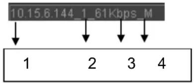
text_image
10.15.6.144_1_61Kbps_M ↓ 1 2 3 4Figure 5-9
On the top right corner, there are six unction buttons. See Figure 5-10.
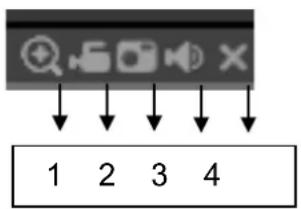
text_image
1 2 3 4Figure 5-10
- 1: Digital zoom: Click this button and then left drag the mouse in the zone to zoom in. right click mouse system restores original status.
- 2: Local record. When you click local record button, the system begins recording and this button becomes highlighted. You can go to system folder RecordDownload to view the recorded file.
- 3: Snapshot picture. You can snapshot important video. All images are memorized in system client folder PictureDownload (default).
● 4: Audio :Turn on or off audio.(It has no relationship with system audio setup )
5: Close video.
PTZ
Before PTZ operation, please make sure you have properly set PTZ protocol.
There are eight direction keys. In the middle of the eight direction keys, there is a 3D intelligent positioning key.
Click 3D intelligent positioning key, system goes back to the single screen mode. Drag the mouse in the screen to adjust section size. It can realize PTZ automatically.
Please refer to the following sheet for PTZ setup information.
| Parameter | Function |
| Scan | Select Scan from the dropdown list.Click Set button, you can set scan left and right limit.Use direction buttons to move the camera to you desired location and then click left limit button. Then move the camera again and then click right limit button to set a right limit. |
| Preset | Select Preset from the dropdown list.Turn the camera to the corresponding position and Input the preset value. Click Add button to add a preset. |
| Tour | Select Tour from the dropdown list.Input preset value in the column. Click Add preset button, you have added one preset in the tour.Repeat the above procedures you can add more presets in one tour.Or you can click delete preset button to remove one preset from the tour. |
| Pattern | Select Pattern from the dropdown list.You can input pattern value and then click Start button to begin PTZ movement such as zoom, focus, iris, direction and etc.Then you can click Add button to set one pattern. |
| Aux | Please input the corresponding aux value here.You can select one option and then click AUX on or AUX off button. |
| Light and wiper | You can turn on or turn off the light/wiper. |

text_image
3D Intelligent Positioning Key Speed(1-8): 5 Zoom Focus Iris PTZ PTZ Menu Scan Start Set You can click this icon to display or hide the PTZ control platform. On Off SaveFigure 5-11
Image
Select one monitor channel video and then click Image button in section 8, the interface is shown as Figure 5-12.
Image
Here you can adjust its brightness, contrast, hue and saturation. (Current channel border becomes green).
Or you can click Reset button to restore system default setup.
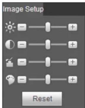
text_image
Image Setup ResetFigure 5-12
WAN Login
In WAN mode, after you logged in, the interface is shown as below. See Figure 5-13.

text_image
WEB SERVICE Live Playback Alarm Setup Info Logout CAM 1 CAM 2 CAM 3 CAM 4 2013-11-24 11:28:54 Start Talk Install Record CAM 1 Copyright 2013 All Rights Reserved. Copyright 2013 All Rights Reserved.Figure 5-13
Please refer to the following contents for LAN and WAN login difference.
1) In the WAN mode, system opens the main stream of the first channel to monitor by default. The open/close button on the left pane is null.
2) You can select different channels and different monitor modes at the bottom of the interface. See Figure 5-14.
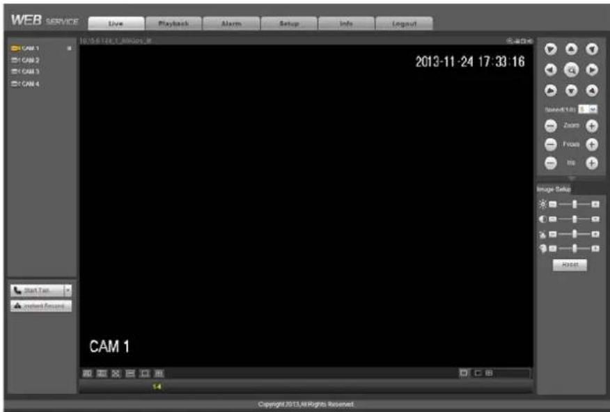
text_image
WEB SERVICE Live Playback Alarm Setup Info Logout CAM 1 CAM 2 CAM 3 CAM 4 2013-11-24 17:33:16 Start Test project Record CAM 1 Copyright 2013.48 Rights ReservedFigure 5-14
Important
The window display mode and the channel number are by default. For example, for the 16-channel, the max window split mode is 16.
3) Multiple-channel monitor, system adopts extra stream to monitor by default. Double click one channel, system switches to single channel and system uses main stream to monitor. You can view there are two icons at the left top corner of the channel number for you reference. M stands for main stream. S stands for sub stream (extra stream).
4) If you login via the WAN mode, system does not support alarm activation to open the video function in the Alarm setup interface.
Important
- For multiple-channel monitor mode, system adopts extra stream to monitor by default. You can not modify manually. All channels are trying to synchronize. Please note the synchronization effect still depends on your network environments.
- For bandwidth consideration, system can not support monitor and playback at the same time. System auto closes monitor or playback interface when you are searching setup in the configuration interface. It is to enhance search speed.
Setup
Camera
Remote Device
Remote device interface is shown as below. See Figure 5-15.
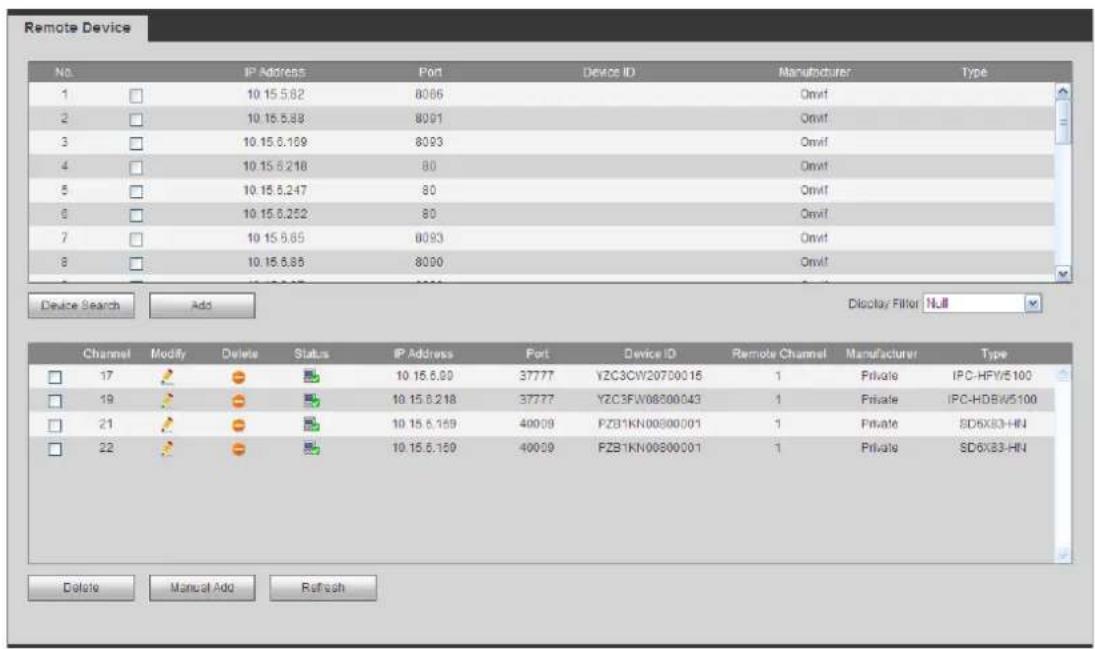
text_image
Remote Device No. IP Address Port Device ID Manufacturer Type 1 10.15.5.82 8066 Onvif 2 10.15.5.83 8091 Onvif 3 10.15.5.169 8093 Onvif 4 10.15.5.218 80 Onvif 5 10.15.5.247 80 Onvif 6 10.15.5.252 80 Onvif 7 10.15.5.65 8093 Onvif 8 10.15.5.85 8090 Onvif Device Search Add Display Filter Null Channel Modify Delete Status IP Address Port Device ID Remote Channel Manufacturer Type 17 19 21 22 10.15.5.90 37777 YZC3CW20700015 1 Private IPC-HFW5100 10.15.5.218 37777 YZC3FW08000043 1 Private IPC-HDBW5100 10.15.5.169 40009 FZB1KN00800001 1 Private SD6X83-HN 10.15.5.159 40009 FZB1KN00800001 1 Private SD6X83-HN Delete Manual Add RefreshFigure 5-15

text_image
Manual Add Channel 18 Manufacturer Private IP Address 192.168.0.0 TCP Port 37777 (1~65535) User Name admin Password •••••• Remote Channel No. 1 Decode Buffer 280 ms (80~480) Save CancelFigure 5-16
Please refer to the following sheet for log parameter information.
| Parameter | Function |
| Device search | Click Device search button, you can view the searched device information on the list. It includes device IP address, port, device name, manufacturer and type. |
| Add | Select a device in the list and then click Add button, system can connect the device automatically and add it to the Added device list. Or you can double click one item in the list to add a device. |
| Modify | Click 🎨 or any device in the Added device list, you can change the corresponding channel setup. |
| Delete | Click ✕ , you can delete the remote connection of the corresponding channel. |
| Connection status | : Connection succeeded.: Connection failed. |
| Delete | Select a device in the Added device list and then click Delete button, system can disconnect the device and remove it from the Added device list. |
| Manual Add | Click it, the interface is shown as in Figure 5-16. Here you can add network camera manually.You can select a channel from the dropdown list (Here only shows disconnection channel.)Note:System supports manufactures such as Panasonic, Sony, Dynacolor, Samsung, AXIS, Arecont, Dahua and Onvif standard protocol.If you do not input IP address here. System uses default IP 192.168.0.0 and system does not connect to this IP.Can not add two devices at the same time. Click OK button here, system only connect to the corresponding device of current channel. |
Conditions
Here you can view device property information. The setups become valid immediately after you set. See Figure 5-17 (analog channel) and Figure 5-18 (digital channel).
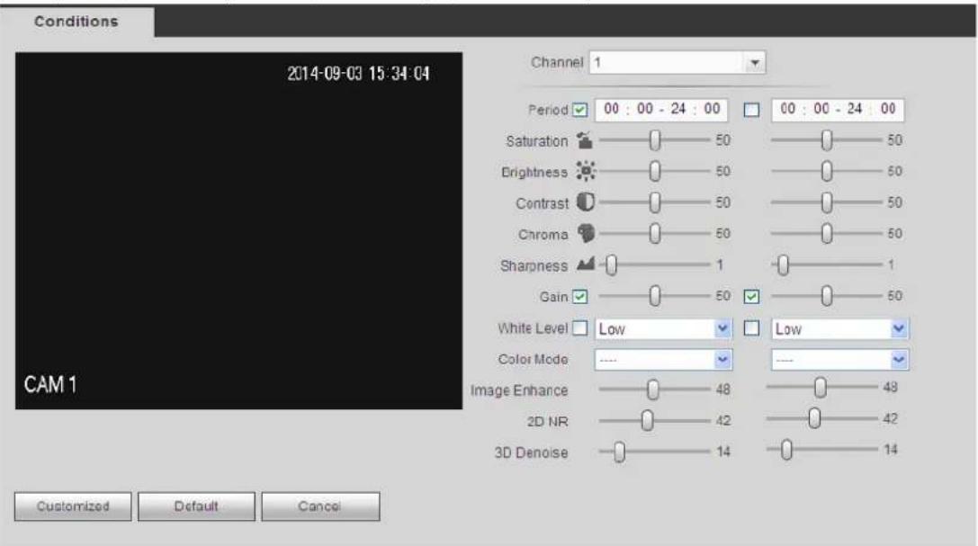
text_image
Conditions 2014-09-03 15:34:04 Channel 1 Period 00 : 00 - 24 : 00 00 : 00 - 24 : 00 Saturation 50 50 Brightness 50 50 Contrast 50 50 Chroma 50 50 Sharpness 1 1 Gain 50 50 White Level Low Low Color Mode .... Image Enhance 48 48 2D NR 42 42 3D Denoise 14 14 Customized Default CancelFigure 5-17
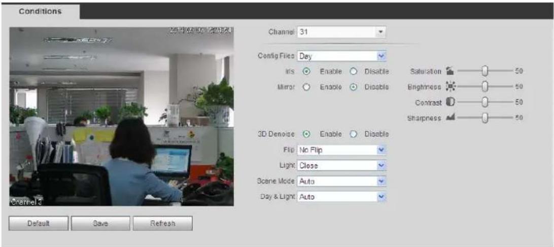
text_image
Conditions Channel 31 Config Files Day Iris Enable Disable Mirror Enable Disable Saturation 50 Brightness 50 Contrast 50 Sharpness 50 3D Denoise Enable Disable Flip No Flip Light Close Scene Mode Auto Day & Light Auto Default Save RefreshFigure 5-18
Please refer to the following sheet for detailed information.
| Parameter Function | ||
| Channel | Please select a channel from the dropdown list. | |
| Period | It divides one day (24 hours) to two periods. You can set different hue, brightness, and contrast for different periods. | |
| Hue | It is to adjust monitor video brightness and darkness level. The default value is 50.The bigger the value is, the large the contrast between the bright and dark section is and vice versa. | |
| Brightness | It is to adjust monitor window brightness. The default value is 50.The larger the number is , the bright the video is. When you input the value here, the bright section and the dark section of the video will be adjusted accordingly. You can use this function when the whole video is too dark or too bright. Please note the video may become hazy if the value is too high. The value ranges from 0 to 100.The recommended value ranges from 40 to 60. | |
| Contrast | It is to adjust monitor window contrast. The value ranges from 0 to 100. The default value is 50.The larger the number is, the higher the contrast is. You can use this function when the whole video bright is OK but the contrast is not proper. Please note the video may become hazy if the value is too low. If this value is too high, the dark section may lack brightness while the bright section may over exposure .The recommended value ranges from 40 to 60. | |
| Saturation | It is to adjust monitor window saturation. The value ranges from 0 to 100. The default value is 50.The larger the number is, the strong the color is. This value has no effect on the general brightness of the whole video. The video color may become too strong if the value is too high. For the grey part of the video, the distortion may occur if the white balance is not accurate. Please note the video may not be attractive if the value is too low. The recommended value | |
| ranges from 40 to 60. | ||
| Gain | The gain adjust is to set the gain value. The smaller the value is, the low the noise is. But the brightness is also too low in the dark environments. It can enhance the video brightness if the value is high. But the video noise may become too clear. | |
| White level | It is to enhance video effect. | |
| Color mode | It includes several modes such as standard, color. You can select corresponding color mode here, you can see hue, brightness, and contrast and etc will adjust accordingly. | |
| Auto Iris | It is to enable/disable auto iris function. | |
| Flip | It is to switch video up and bottom limit.This function is disabled by default. | |
| Mirror | It is to switch video left and right limit.This function is disabled by default. | |
| BLC Mode | BLC | The device auto exposures according to the environments situation so that the darkest area of the video is cleared |
| WDR | For the WDR scene, this function can lower the high bright section and enhance the brightness of the low bright section. So that you can view these two sections clearly at the same time.The value ranges from 1 to 100. When you switch the camera from no-WDR mode to the WDR mode, system may lose several seconds record video. | |
| HLC | After you enabled HLC function, the device can lower the brightness of the brightest section according to the HLC control level. It can reduce the area of the halo and lower the brightness of the whole video. | |
| Off | It is to disable the BLC function. Please note this function is disabled by default. | |
| Profile | It is to set the white balance mode. It has effect on the general hue of the video. This function is on by default.You can select the different scene mode such as auto, sunny, cloudy, home, office, night, disable and etc to adjust the video to the best quality.Auto: The auto white balance is on. System can auto compensate the color temperature to make sure the vide color is proper.Sunny: The threshold of the white balance is in the sunny mode.Night: The threshold of the white balance is in the night mode.Customized: You can set the gain of the red/blue channel. The value reneges from 0 to 100. | |
| Day/Night | It is to set device color and the B/W mode switch. The default setup is auto.Color: Device outputs the color video. | |
| ● Auto: Device auto select to output the color or the B/W video according to the device feature (The general bright of the video or there is IR light or not.)● B/W: The device outputs the black and white video.● Sensor: It is to set when there is peripheral connected IR light. | ||
Encode
Encode
The encode interface is shown as below. See Figure 5-19.

text_image
Encode Snapshot Overlay Path Channel 1 Main Stream Sub Stream Code-Stream Type Regular Compression H.264 Resolution 720P Frame Rate(FPS) 25 Bit Rate Type CER Bit Rate 2048 Kb/S Reference Bit Rate 0-0Kb/S 1 Frame Interval 1 Second Video Enable Compression H.264 Resolution CIF Frame Rate(FPS) 6 Bit Rate Type CBR Bit Rate 160 Kb/S Reference Bit Rate 0-0Kb/S 1 Frame Interval 1 Second Audio Enable Audio Enable Audio Encode G711a Audio Source NORMAL Audio Source G711a NORMAL Watermark Enable Watermark String Copy Save Refresh DefaultFigure 5-19
Please refer to the following sheet for detailed information.
| Parameter Function | |
| Channel | Please select a channel from the dropdown list. |
| Video enable | Check the box here to enable extra stream video. This item is enabled by default. |
| Code stream type | It includes main stream, motion stream and alarm stream. You can select different encode frame rates form different recorded events.System supports active control frame function (ACF). It allows you to record in different frame rates.For example, you can use high frame rate to record important events, record scheduled event in lower frame rate and it allows you to set different frame rates for motion detection record and alarm record. |
| Compression | The main bit stream supports H.264. The extra stream supports H.264, MJPG. |
| Resolution | System supports various resolutions, you can select from the dropdown list. The main stream supports 1080P/720P/960H/D1/HD1/2CIF/CIF/QCIF; the extra stream supports CIF/QCIF. Please note the option may vary due to different series. |
| Frame Rate | PAL: 1~25f/s; NTSC: 1~30f/s. |
| Bit Rate | ● Main stream: You can set bit rate here to change video quality. The large the bit rate is, the better the quality is. Please refer to recommend bit rate for the detailed information.● Extra stream: In CBR, the bit rate here is the max value. In dynamic video, system needs to low frame rate or video quality to guarantee the value. The value is null in VBR mode. |
| Reference bit rate | Recommended bit rate value according to the resolution and frame rate you have set. |
| I Frame | Here you can set the P frame amount between two I frames. The value ranges from 1 to 150. Default value is 50. Recommended value is frame rate *2. |
| Audio source | Please select from the dropdown list. There are two options: Normal/HDUTC. In the normal mode, the audio signal comes from the Audio In. In the HDUTC mode, the audio signal comes from the coaxial cable of the camera. |
| Watermark enable | This function allows you to verify the video is tampered or not. Here you can select watermark bit stream, watermark mode and watermark character. Default character is DigitalCCTV. The max length is 85-digit. The character can only include number, character and underline. |
Snapshot
The snapshot interface is shown as in Figure 5-20.

text_image
Encode Snapshot Overlay Path Channel 1 Mode Regular Image Size CIF (362*288) Quality 4 Interval 1 S Copy Save Refresh DefaultFigure 5-20
Please refer to the following sheet for detailed information.
| Parameter Function | |
| Snapshot type | There are two modes: Regular (schedule) and Trigger.● Regular snapshot is valid during the specified period you set.● Trigger snapshot only is valid when motion detect alarm, tampering alarm or local activation alarm occurs. |
| Image size | It is the same with the resolution of the main stream. |
| Quality | It is to set the image quality. There are six levels. |
| Interval | It is to set snapshot frequency. The value ranges from 1s to 7s. Or you can set customized value. The max setup is 3600s/picture. |
| Copy | Click it; you can copy current channel setup to other channel(s). |
Video Overlay
The video overlay interface is shown as in Figure 5-21.

text_image
Encode Snapshot Overlay Path 2013-10-24 17:00:05 Channel 1 Cover Area Preview Monitor Channel Display Setup Time Display Setup CAM 1 Copy Save Refresh DefaultFigure 5-21
Please refer to the following sheet for detailed information.
| Parameter Function | |
| Cover-area | Check Preview or Monitor first.Click Set button, you can privacy mask the specified video in the preview or monitor video.System max supports 4 privacy mask zones. |
| Time Title | You can enable this function so that system overlays time information in video window.You can use the mouse to drag the time title position.You can view time title on the live video of the WEB or the playback video. |
| Channel Title | You can enable this function so that system overlays channel information in video window.You can use the mouse to drag the channel title position.You can view channel title on the live video of the WEB or the playback video. |
Path
The storage path interface is shown as in Figure 5-22.
Holis HD Series DVR User Manual 4, 8 & 16 Channel Models
Here you can set snap image saved path (in the preview interface) and the record storage path

in the preview interface).The default setup is C:\PictureDownload and C:\RecordDownload.
Please click the Save button to save current setup.
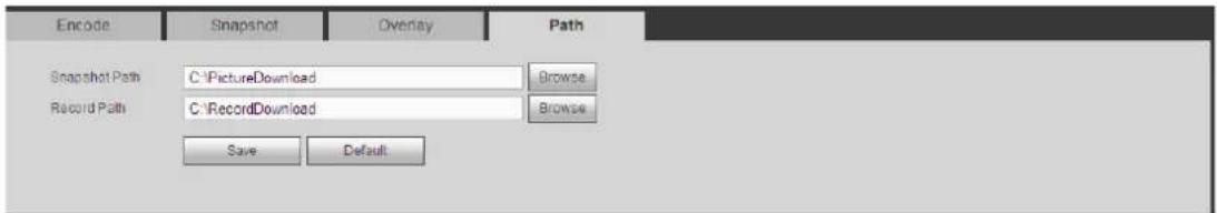
text_image
Encode Snapshot Overlay Path Snapshot Path C:\PictureDownload Browse Record Path C:\RecordDownload Browse Save DefaultFigure 5-22
Channel Name
Here you can set channel name. See Figure 5-23.

text_image
Camera Name Channel 1 CAM 1 Channel 2 CAM 2 Channel 3 CAM 3 Channel 4 CAM 4 Channel 5 CAM 5 Channel 6 CAM 6 Channel 7 CAM 7 Channel 8 CAM 8 Channel 9 CAM 9 Channel 10 CAM 10 Channel 11 CAM 11 Channel 12 CAM 12 Save Refresh DefaultFigure 5-23
Channel Type
It is to set channel type. Each channel supports analog camera (analog standard definition/HDCVI) /network camera connection. Please note DVR needs to restart to activate new setup. The network camera connection shall begin with the last channel. See Figure 5-24.
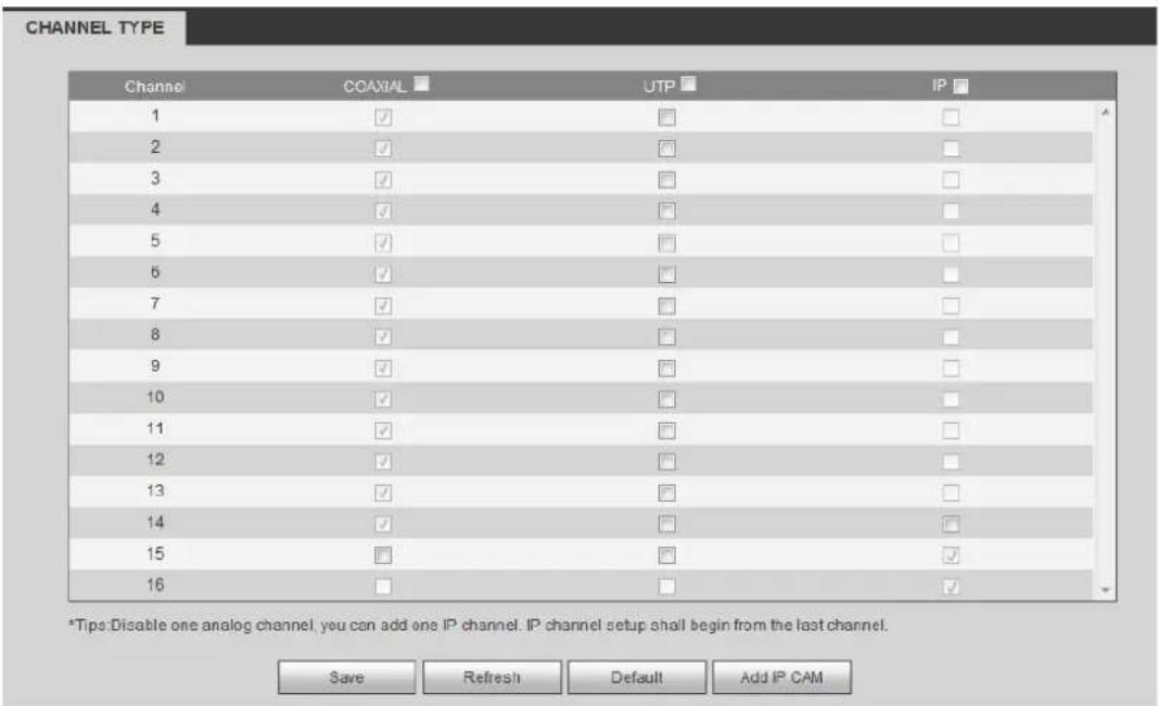
text_image
CHANNEL TYPE Channel COAXIAL UTP IP 1 ✓ □ □ 2 ✓ □ □ 3 ✓ □ □ 4 ✓ □ □ 5 ✓ □ □ 6 ✓ □ □ 7 ✓ □ □ 8 ✓ □ □ 9 ✓ □ □ 10 ✓ □ □ 11 ✓ □ □ 12 ✓ □ □ 13 ✓ □ □ 14 ✓ □ □ 15 □ □ ✓ 16 □ □ ✓ *Tips:Disable one analog channel, you can add one IP channel. IP channel setup shall begin from the last channel. Save Refresh Default Add IP CAMFigure 5-24
Network
TCP/IP
The TCP/IP interface is shown as in Figure 5-25.

text_image
TCP/IP Mode ○ STATIC ○ DHCP MAC Address 90:02 a9 ba 37:38 MTU 1500 IP Version IPv4 IP Address 10 15 6 144 Subnet Mask 255 255 0 0 Default Gateway 10 15 0 1 Preferred DNS 10 1 2 80 Alternate DNS 10 1 2 81 □ LAN Download Save Refresh DefaultFigure 5-25
Please refer to the following sheet for detailed information.
| Parameter Function | |
| Mode | There are two modes: static mode and the DHCP mode.The IP/submask/gateway are null when you select the DHCP mode to auto search the IP.If you select the static mode, you need to set theIP/submask/gateway manually.● If you select the DHCP mode, you can view the IP/submask/gateway from the DHCP.● If you switch from the DHCP mode to the static mode, you need to reset the IP parameters.● Besides, IP/submask/gateway and DHCP are read-only when the PPPoE dial is OK. |
| Mac Address | It is to display host Mac address. |
| IP Version | It is to select IP version. IPV4 or IPV6.You can access the IP address of these two versions. |
| IP Address | Please use the keyboard to input the corresponding number to modify the IP address and then set the corresponding subnet mask and the default gateway. |
| Preferred DNS DNS IP address. | |
| Alternate DNS | Alternate DNS IP address. |
| For the IP address of IPv6 version, default gateway, preferred DNS and alternate DNS, the input value shall be 128-digit. It shall not be left in blank. | |
| LAN load | System can process the downloaded data first if you enable this function. The download speed is 1.5X or 2.0X of the normal speed. |
Connection
The connection interface is shown as in Figure 5-26.

text_image
Connection Max Connection 128 (0-128) TCP Port 37777 (200-65535) UDP Port 37778 (200-65535) HTTP Port 80 (1-65535) HTTPS Port 443 (128-65535) RTSP Port 554 (128-65535) RTSP Format rtsp/IR User Name:Figure 5-26
Please refer to the following sheet for detailed information.
| Parameter Function | |
| Max connection | It is the max Web connection for the same device. The value ranges from 1 to 120. The default setup is 120. |
| TCP port | The default value is 37777. You can input the actual port number if necessary. |
| UDP port | The default value is 37778. You can input the actual port number if necessary. |
| HTTP port | The default value is 80. You can input the actual port number if necessary. |
| HTTPS | The default value is 443. You can input the actual port number if necessary. |
| RTSP port The de | default value is 554. |
PPPoE
The PPPoE interface is shown as in Figure 5-27.
Input the PPPoE user name and password you get from the IPS (internet service provider) and enable PPPoE function. Please save current setup and then reboot the device to get the setup activated.
Device connects to the internet via PPPoE after reboot. You can get the IP address in the WAN from the IP address column.
Note:
You need to use previous IP address in the LAN to login the device. Please go to the IP address item to via the device current device information. You can access the client-end via this new address.

text_image
PPPoE Enable User Name: Password: IP Address: 0 0 0 0 0 0 0 0 Save Refresh DefaultFigure 5-27
DDNS
The DDNS interface is shown as in Figure 5-28.
The DDNS is to set to connect the various servers so that you can access the system via the server.
Please go to the corresponding service website to apply a domain name and then access the system via the domain. It works even your IP address has changed.
Please select DDNS from the dropdown list (Multiple choices). Before you use this function, please make sure your purchased device support current function.

text_image
DDNS Enable DDNS Type Quick DONS Server IP www.quickddns.com Domain Mode Default Custom Name Domain Name 201310131632 quickddns.com Test Email (Optional/Please input email address. Save Refresh DefaultFigure 5-28
Please refer to the following sheet for detailed information.
| Parameter Function | |
| Server Type | You can select DDNS protocol from the dropdown list and then enable DDNS function. |
| Server IP | DDNS server IP address |
| Server Port DDNS server port. | |
| Domain Name | Your self-defined domain name. |
| User | The user name you input to log in the server. |
| Password The p | password you input to log in the server. |
| Update period | Device sends out alive signal to the server regularly.You can set interval value between the device and DDNS server here. |
Quick DDNS and Client-end Introduction
1) Background Introduction
Device IP is not fixed if you use ADSL to login the network. The DDNS function allows you to access the DVR via the registered domain name. Besides the general DDNS, the quick DDNS works with the device from the manufacturer so that it can add the extension function.
2) Function Introduction
The quick DDNS client has the same function as other DDNS client end. It realizes the bonding of the domain name and the IP address. Right now, current DDNS server is for our own devices only. You need to refresh the bonding relationship of the domain and the IP regularly. There is no user name, password or the ID registration on the server. At the same time, each device has a default domain name (Generated by MAC address) for your option. You can also use customized valid domain name (has not registered.).
3) Operation
Before you use Quick DDNS, you need to enable this service and set proper server address, port value and domain name.
- Server address: www.quickddns.com
- Port number: 80
- Domain name: There are two modes: Default domain name and customized domain name.
Except default domain name registration, you can also use customized domain name (You can input your self-defined domain name.) After successful registration, you can use domain name to login installed of the device IP.
- User name: It is optional. You can input your commonly used email address.
Important
- Do not register frequently. The interval between two registrations shall be more than 60 seconds. Too many registration requests may result in server attack.
- System may take back the domain name that is idle for one year. You can get a notification email before the cancel operation if your email address setup is OK.
IP filter
The IP filter interface is shown as in Figure 5-29.
After you enabled trusted sites function, only the IP listed below can access current DVR. If you enable blocked sites function, the following listed IP addresses cannot access current DVR.

text_image
IP Filter Enable Trusted Sites Blocked Sites Trusted Sites Blocked Sites IP Address Edit Delete Add Save Refresh DefaultFigure 5-29
The email interface is shown as in Figure 5-30.
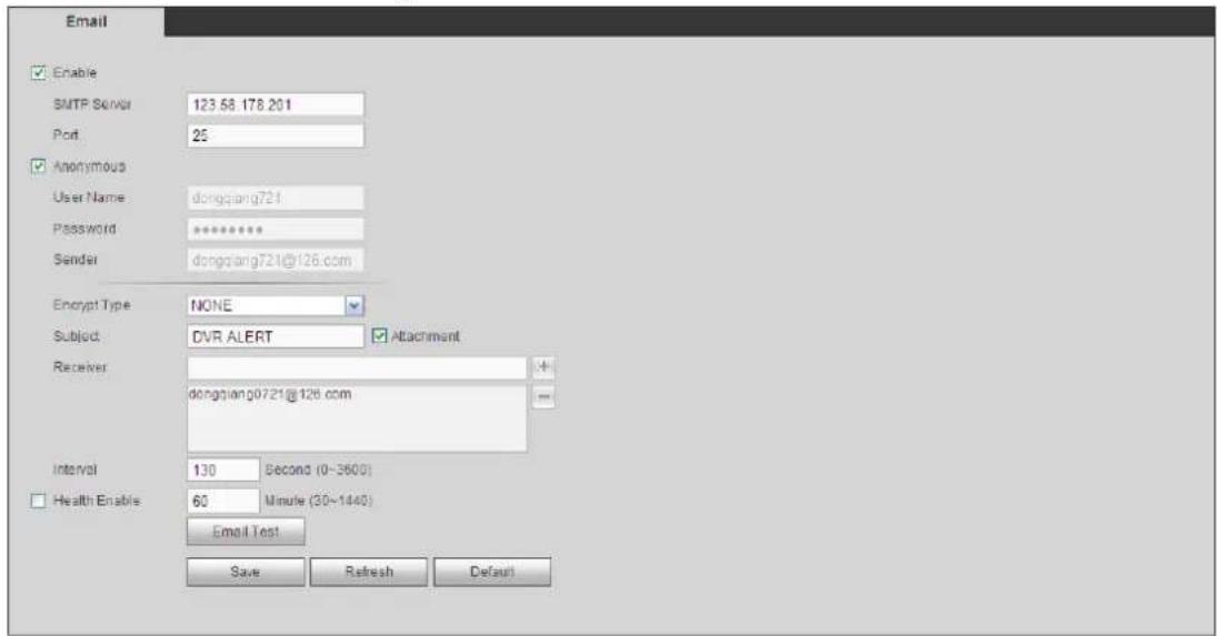
text_image
Email Enable SMTP Server 123.58.178.201 Port 25 Anonymous User Name dongqiang721 Password ********** Sender dongqiang721@126.com Encrypt Type NONE Subject: DVR ALERT Attachment Receiver: dongqiang0721@126.com Interval 130 Second (0~3600) Health Enable 60 Minute (30~1440) Email Test Save Refresh DefaultFigure 5-30
Please refer to the following sheet for detailed information.
| Parameter Function | |
| Enable | Please check the box here to enable email function. |
| SMTP Server | Input server address and then enable this function. |
| Port | Default value is 25. You can modify it if necessary. |
| Anonymity | For the server supports the anonymity function. You can auto login anonymously. You do not need to input the user name. password and the sender information. |
| Parameter Function | |
| User Name | The user name of the sender email account. |
| Password | The password of sender email account. |
| Sender | Sender email address. |
| Authentication (Encryption mode) | You can select SSL or none. |
| Subject | Input email subject here. |
| Attachment | System can send out the email of the snapshot picture once you check the box here. |
| Receiver | Input receiver email address here. Max three addresses. It supports SSL, TLS email box. |
| Interval | The send interval ranges from 0 to 3600 seconds. 0 means there is no interval.Please note system will not send out the email immediately when the alarm occurs. When the alarm, motion detection or the abnormality event activates the email, system sends out the email according to the interval you specified here. This function is very useful when there are too many emails activated by the abnormality events, which may result in heavy load for the email server. |
| Health mail enable | Please check the box here to enable this function. |
| Update period (interval) | This function allows the system to send out the test email to check the connection is OK or not.Please check the box to enable this function and then set the corresponding interval. The value ranges from 30 minutes to 1440 minutes.System can send out the email regularly as you set here. |
| Email test | The system will automatically sent out a email once to test the connection is OK or not .Before the email test, please save the email setup information. |
FTP
The FTP interface is shown as in Figure 5-31.
It is to set FTP IP, port and etc for remote storage.
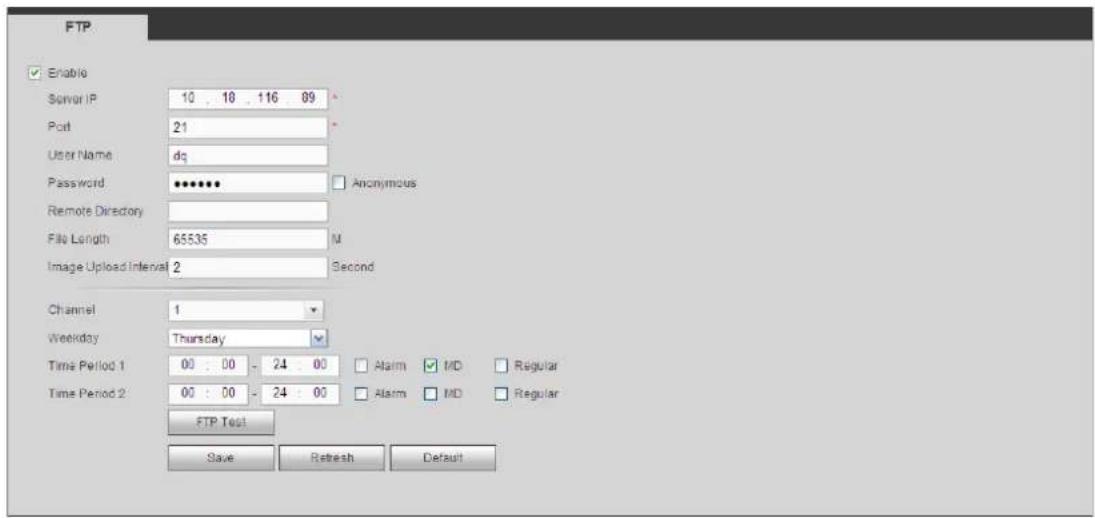
text_image
FTP Enable Server IP 10 , 18 , 116 , 89 * Port 21 * User Name dg Password ••••••• Anonymous Remote Directory File Length 65535 M Image Upload Interval 2 Second Channel 1 Weekday Thursday Time Period 1 00 : 00 - 24 : 00 Alarm MD Regular Time Period 2 00 : 00 - 24 : 00 Alarm MD Regular FTP Test Save Refresh DefaultFigure 5-31
UPnP
It allows you to establish the mapping relationship between the LAN and the public network. Here you can also add, modify or remove UPnP item. See Figure 5-32.
- In the Windows OS, From Start->Control Panel->Add or remove programs. Click the "Add/Remove Windows Components" and then select the "Network Services" from the Windows Components Wizard.
- Click the Details button and then check the "Internet Gateway Device Discovery and Control client" and "UPnP User Interface". Please click OK to begin installation.
- Enable UPnP from the Web. If your UPnP is enabled in the Windows OS, the DVR can auto detect it via the "My Network Places"

text_image
UPnP PAT Enacle Disable Status LAN IP 0 0 0 0 WAN IP 0 0 0 0 Port Mapping List No. ✓ Service Name Protocol Internal Port External Port Modify Delete 1 ✓ HTTP TCP 80 80 ✓ - 2 ✓ TCP TCP 37777 37777 ✓ - 3 ✓ UDP UDP 37778 37778 ✓ - 4 ✓ RTSP UDP 554 554 ✓ - 5 ✓ RTSP TCP 554 554 ✓ - 6 ✓ SNMP UDP 161 161 ✓ - 7 ✓ HTTPS TCP 443 443 ✓Figure 5-32
Please refer to the following sheet for detailed information.
| Parameter Function | |
| PAT | Check the corresponding box to enable PAT function. |
| Status | Display UPnP function status. |
| Port mapping list | It is corresponding to the UPnP mapping information on the router.Check the box before the service name to enable current PAT service.Otherwise, the service is null.Service name: Customized name.Protocol: Protocol type.Internal port: The port mapped to the port.External port: The port current device needs to map.Device has three mapping items: HTTP/TCP/UDP.NoteWhen you set the external port (outport) of the router, the value ranges from 1024 to 5000. Do not use port 1~255 or system port 256~1023, in case there is conflict. |
| Add | Click Add button to add map relationship.NoteFor the data transmission protocol TCP/UDP, the external port and the internal port shall be the same to guarantee proper data transmission. |
| Delete | Select one service and then click → to delete map relationship. |
SNMP
The SNMP interface is shown as in Figure 5-33.
The SNMP allows the communication between the network management work station software and the proxy of the managed device. It is reserved for the 3^rd party to develop.

text_image
SNMP Enable SNMP Port 161 (0-85535) Read Community public Write Community private Trap Address Trap Port 162 (0-85535) SNMP Version V1 V2 Save Refresh DefaultFigure 5-33
Please refer to the following sheet for detailed information.
| Parameter Function | |
| SNMP Port | The listening port of the proxy program of the device. It is a UDP port not a TCP port. The value ranges from 1 to 65535. The default value is 161 |
| Read Community | It is a string. It is a command between the manage process and the proxy process. It defined the authentication, access control and the management relationship between one proxy and one group of the managers. Please make sure the device and the proxy are the same.The read community will read all the objects the SNMP supported in the specified name. The default setup is public. |
| Write Community | It is a string. It is a command between the manage process and the proxy process. It defined the authentication, access |
| Parameter Function | |
| control and the management relationship between one proxy and one group of the managers. Please make sure the device and the proxy are the same.The read community will read/write/access all the objects the SNMP supported in the specified name. The default setup is write. | |
| Trap address | The destination address of the Trap information from the proxy program of the device. |
| Trap port | The destination port of the Trap information from the proxy program of the device. It is for the gateway device and the client-end PC in the LAN to exchange the information. It is a non-protocol connection port. It has no effect on the network applications. It is a UDP port not TCP port. The value ranges from 1 to 165535. The default value is 162. |
| SNMP version | ● Check V1, system only processes the information of V1.● Check V2, system only processes the information of V2. |
Multicast
The multicast interface is shown as in Figure 5-34.
Multicast is a transmission mode of data packet. When there is multiple-host to receive the same data packet, multiple-cast is the best option to reduce the broad width and the CPU load. The source host can just send out one data to transit. This function also depends on the relationship of the group member and group of the outer.
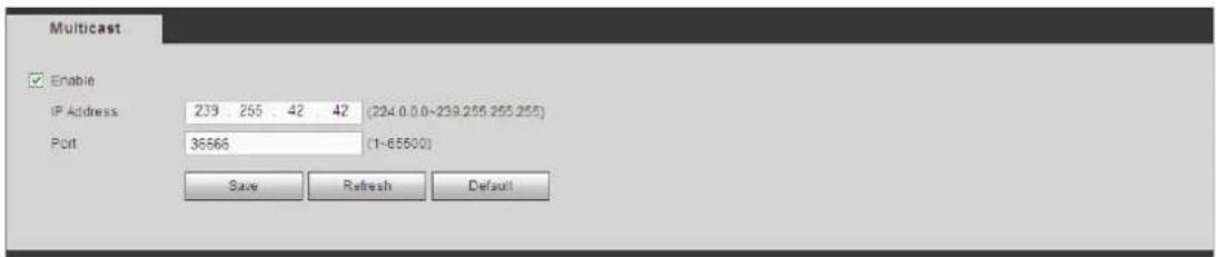
text_image
Multicast Enable IP Address 239 255 42 42 (204.0.0~239.255.255.255) Port 36666 (1~65500) Save Refresh DefaultFigure 5-34
Auto Register
The auto register interface is shown as below. See Figure 5-35.
This function allows the device to auto register to the proxy you specified. In this way, you can use the client-end to access the DVR and etc via the proxy. Here the proxy has a switch function. In the network service, device supports the server address of IPv4 or domain.
Please follow the steps listed below to use this function.
Please set proxy server address, port, and sub-device name at the device-end. Please enable the auto register function, the device can auto register to the proxy server.
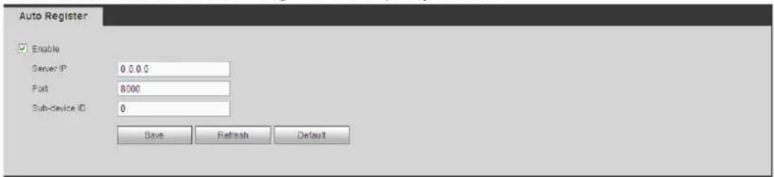
text_image
Auto Register Enable Server IP 0.0.0 Port 8000 Sub-device ID 0 Save Refresh DefaultHolis HD Series DVR User Manual 4, 8 & 16 Channel Models
Figure 5-35
Alarm Centre
The alarm centre interface is shown as below. See Figure 5-36.
This interface is reserved for you to develop. System can upload alarm signal to the alarm centre when local alarm occurs.
Before you use alarm centre, please set server IP, port and etc. When an alarm occurs, system can send out data as the protocol defined, so the client-end can get the data.

text_image
Alarm Centre Enable Protocol Type: Private Server IP: 10 1 0 2 Port: 1 SendReport Time: Everyday at 00:00 Save Refresh DefaultFigure 5-36
P2P
You can use your cell phone to scan the QR code and add it to the cell phone client.
Via the SN from scanning the QR code, you can access the device in the WAN. Please refer to the P2P operation manual included in the resources CD.
The P2P interface is shown as in Figure 5-37.
Check the Enable box to enable P2P function and then click the Save button. Now you can view the device status and SN.

text_image
Enable Status Online Device SN 1M00AD7YAZGX7W5 Save RefreshFigure 5-37
HTTPS
Holis HD Series DVR User Manual 4, 8 & 16 Channel Models
In this interface, you can set to make sure the PC can successfully login via the HTTPS. It is to guarantee communication data security. The reliable and stable technology can secure the user information security and device safety. See Figure 5-38.
Note
- You need to implement server certificate again if you have changed device IP.
- You need to download root certificate if it is your first time to use HTTPS on current PC.

text_image
HTTPS Create Server Certificate Download Root CertificateFigure 5-38
Create Server Certificate
If it is your first time to use this function, please follow the steps listed below.
In Figure 5-38, click Create Server Certificate button, input country name, state name and etc. Click Create button. See Figure 5-39.
Note
Please make sure the IP or domain information is the same as your device IP or domain name.
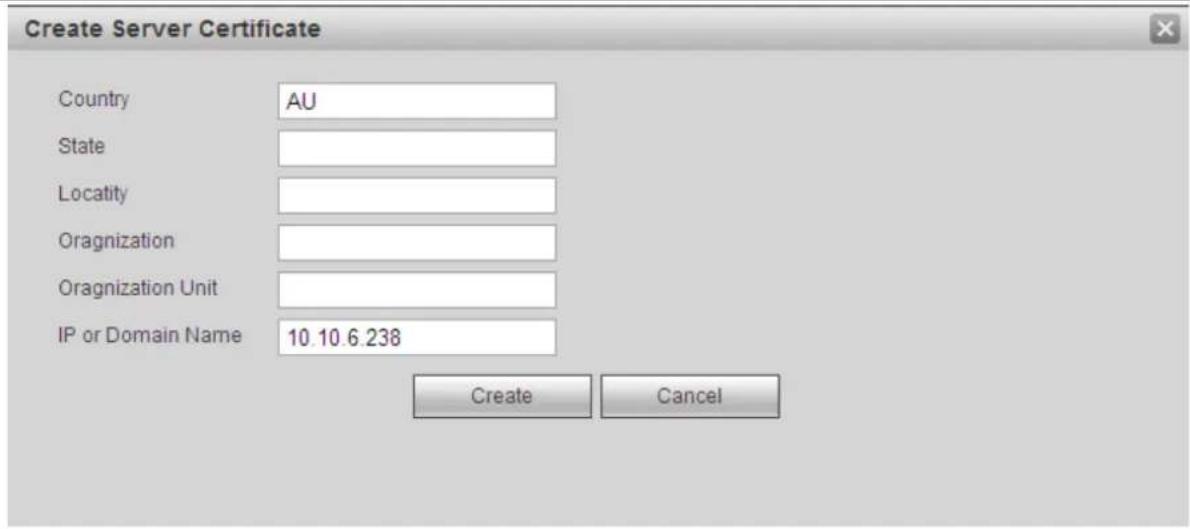
text_image
Create Server Certificate Country AU State Locality Oragnization Oragnization Unit IP or Domain Name 10.10.6.238 Create CancelFigure 5-39
You can see the corresponding prompt. See Figure 5-40. Now the server certificate is successfully created.
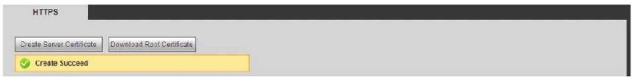
text_image
HTTPS Create Server Certificate Download Root Certificate ✓ Create SucceedFigure 5-40
Download root certificate
Holis HD Series DVR User Manual 4, 8 & 16 Channel Models
In Figure 5-38, click Download Root Certificate button, system pops up a dialogue box. See Figure 5-41.
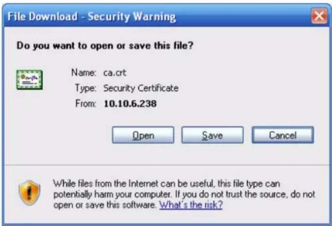
text_image
File Download - Security Warning Do you want to open or save this file? Name: ca.crt Type: Security Certificate From: 10.10.6.238 Open Save Cancel While files from the Internet can be useful, this file type can potentially harm your computer. If you do not trust the source, do not open or save this software. What's the risk?Figure 5-41
Click Open button, you can go to the following interface. See Figure 5-42.
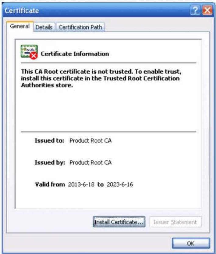
text_image
Certificate Information This CA Root certificate is not trusted. To enable trust, install this certificate in the Trusted Root Certification Authorities store. Issued to: Product Root CA Issued by: Product Root CA Valid from 2013-6-18 to 2023-6-16 Install Certificate... Issuer Statement OKFigure 5-42
Click Install certificate button, you can go to certificate wizard. See Figure 5-43.

text_image
Certificate Import Wizard Welcome to the Certificate Import Wizard This wizard helps you copy certificates, certificate trust lists, and certificate revocation lists from your disk to a certificate store. A certificate, which is issued by a certification authority, is a confirmation of your identity and contains information used to protect data or to establish secure network connections. A certificate store is the system area where certificates are kept. To continue, click Next.Figure 5-43
Click Next button to continue. Now you can select a location for the certificate. See Figure 5-44.
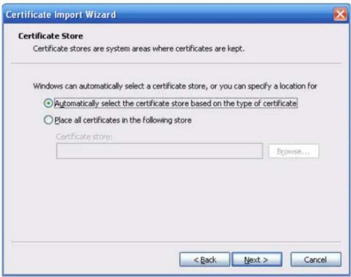
text_image
Certificate Import Wizard Certificate Store Certificate stores are system areas where certificates are kept. Windows can automatically select a certificate store, or you can specify a location for ● Automatically select the certificate store based on the type of certificate ○ Place all certificates in the following store Certificate store: Browse... < Back Next > CancelFigure 5-44
Click Next button, you can see the certificate import process is complete. See Figure 5-45.
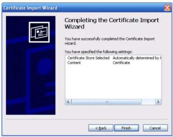
text_image
Certificate Import Wizard Completing the Certificate Import Wizard You have successfully completed the Certificate Import wizard. You have specified the following settings: Certificate Store Selected Automatically determined by t Content Certificate < Back Finish CancelFigure 5-45
Click Finish button, you can see system pops up a security warning dialogue box. See Figure 5-46.
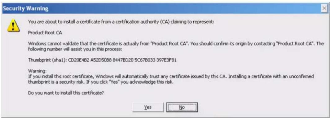
text_image
Security Warning You are about to install a certificate from a certification authority (CA) claiming to represent: Product Root CA Windows cannot validate that the certificate is actually from "Product Root CA". You should confirm its origin by contacting "Product Root CA". The following number will assist you in this process: Thumbprint (sha1): CD20E4B2 A52D50B8 8447BD20 5C67B033 397E3F81 Warning: If you install this root certificate, Windows will automatically trust any certificate issued by this CA. Installing a certificate with an unconfirmed thumbprint is a security risk. If you click "Yes" you acknowledge this risk. Do you want to install this certificate? Yes NoFigure 5-46
Click Yes button, system pops up the following dialogue box, you can see the certificate download is complete. See Figure 5-47.

text_image
Certificate Import Wizard The import was successful. OKFigure 5-47
View and set HTTPS port
From Setup->Network->Connection, you can see the following interface. See Figure 5-48.
You can see HTTPS default value is 443.
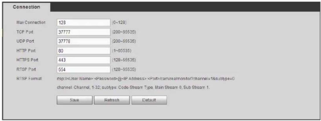
text_image
Connection Max Connection 128 (0~128) TCP Port 37777 (200~65535) UDP Port 37778 (200~65535) HTTP Port 80 (1~65535) HTTPS Port 443 (128~65535) RTSP Port 554 (128~65535) RTSP Format rsp://Figure 5-48
Login
Open the browser and then input https://xx.xx.xx.xx:port.
xx.xx.xx.xx: is your device IP or domain mane.
Port is your HTTPS port. If you are using default HTTPS value 443, you do not need to add port information here. You can input https://xx.xx.xx.xx to access.
Now you can see the login interface if your setup is right.
Event
Video detect
Motion Detect
The motion detect interface is shown as in Figure 5-49.

text_image
Motion Detect Video Loss Tampering Diagnosis Enable 1 Period Setup Anti-dither 5 sec. (0-600) Region Setup Record Channel Setup Delay 10 sec. (10-300) PTZ Activation Setup Tour Setup Snapshot Setup Video Matrix Voice Prompts File Name None Show Message Send Email Buzzer Message Log Alarm Upload Copy Save Refresh DefaultFigure 5-49

text_image
Setup Thursday Copy 00 : 00 - 24 : 00 00 : 00 - 24 : 00 00 : 00 - 24 : 00 00 : 00 - 24 : 00 00 : 00 - 24 : 00 00 : 00 - 24 : 00 00 : 00 - 24 : 00 Save CancelFigure 5-50
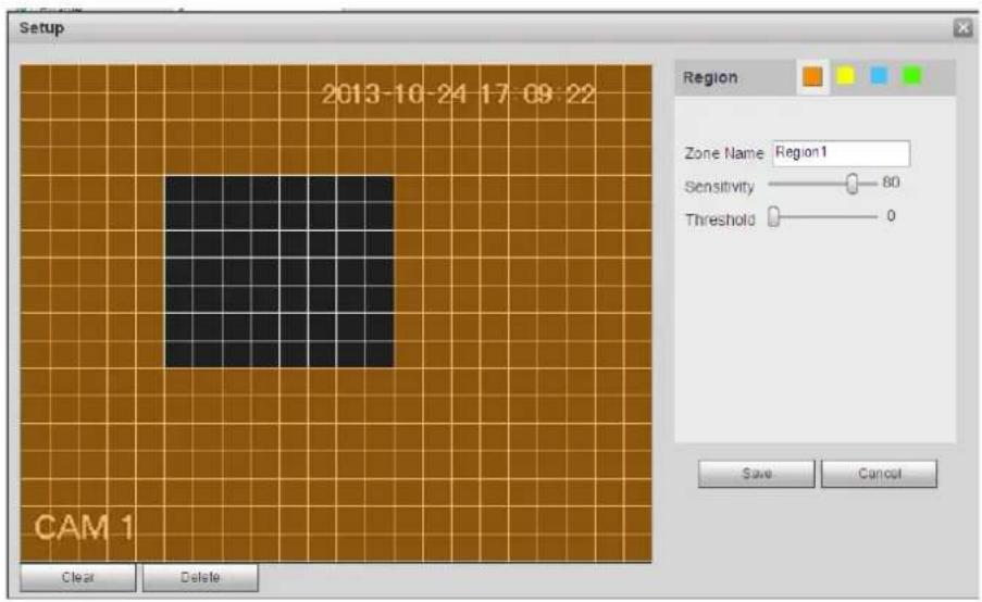
text_image
Setup 2013-10-24 17:09:22 CAM 1 Region Zone Name Region1 Sensitivity 80 Threshold 0 Save CancelFigure 5-51
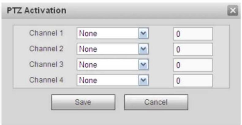
text_image
PTZ Activation Channel 1 None 0 Channel 2 None 0 Channel 3 None 0 Channel 4 None 0 Save CancelFigure 5-52
Please refer to the following sheet for detailed information.
| Parameter Function | |
| Enable | You need to check the box to enable motion detection function. Please select a channel from the dropdown list. |
| Period | Motion detection function becomes activated in the specified periods. See Figure 5-50.There are six periods in one day. Please draw a circle to enable corresponding period.Click OK button, system goes back to motion detection interface, please click save button to exit. |
| Anti-dither | System only memorizes one event during the anti-dither period. The value ranges from 5s to 600s. |
| Sensitivity | There are six levels. The sixth level has the highest sensitivity. |
| Region | If you select motion detection type, you can click this button to set motion detection zone. The interface is shown as in Figure 5-51. Here you can set motion detection zone. There are four zones for you to set. Please select a zone first and then left drag the mouse to select a zone. The corresponding color zone displays different detection zone. You can click Fn button to switch between the arm mode and disarm mode. In arm mode, you can click the direction buttons to move the green rectangle to set the motion detection zone. After you completed the setup, please click ENTER button to exit current setup. Do remember click save button to save current setup. If you click ESC button to exit the region setup interface system will not save your zone setup. |
| Record channel | System auto activates motion detection channel(s) to record once an alarm occurs. Please note you need to set motion detect record period and go to Storage-> Schedule to set current channel as schedule record. |
| Record Delay | System can delay the record for specified time after alarm ended. The value ranges from 10s to 300s. |
| Alarm out | Enable alarm activation function. You need to select alarm output port so that system can activate corresponding alarm device when an alarm occurs. |
| Latch | System can delay the alarm output for specified time after an alarm ended. The value ranges from 1s to 300s. |
| Show message | System can pop up a message to alarm you in the local host screen if you enabled this function. |
| Buzzer | Check the box here to enable this function. The buzzer beeps when an alarm occurs. |
| Alarm upload | System can upload the alarm signal to the centre (Including alarm centre. |
| Message | When 3G network connection is OK, system can send out a message when motion detect occurs. |
| Send Email | If you enabled this function, System can send out an email to alert you when an alarm occurs. |
| Tour | You need to check the box here to enable this function. System begins 1-wiindow or multiple-window tour display among the channel(s) you set to record when an alarm occurs. |
| PTZ Activation | Here you can set PTZ movement when alarm occurs. Such as go to preset X. See Figure 5-52. |
Video Loss
The video loss interface is shown as in Figure 5-53.
After analysis video, system can generate a video loss alarm when the detected moving signal reached the sensitivity you set here.
Please note video loss does not support anti-dither, sensitivity, region setup. For rest setups, please refer to motion detect for detailed information.
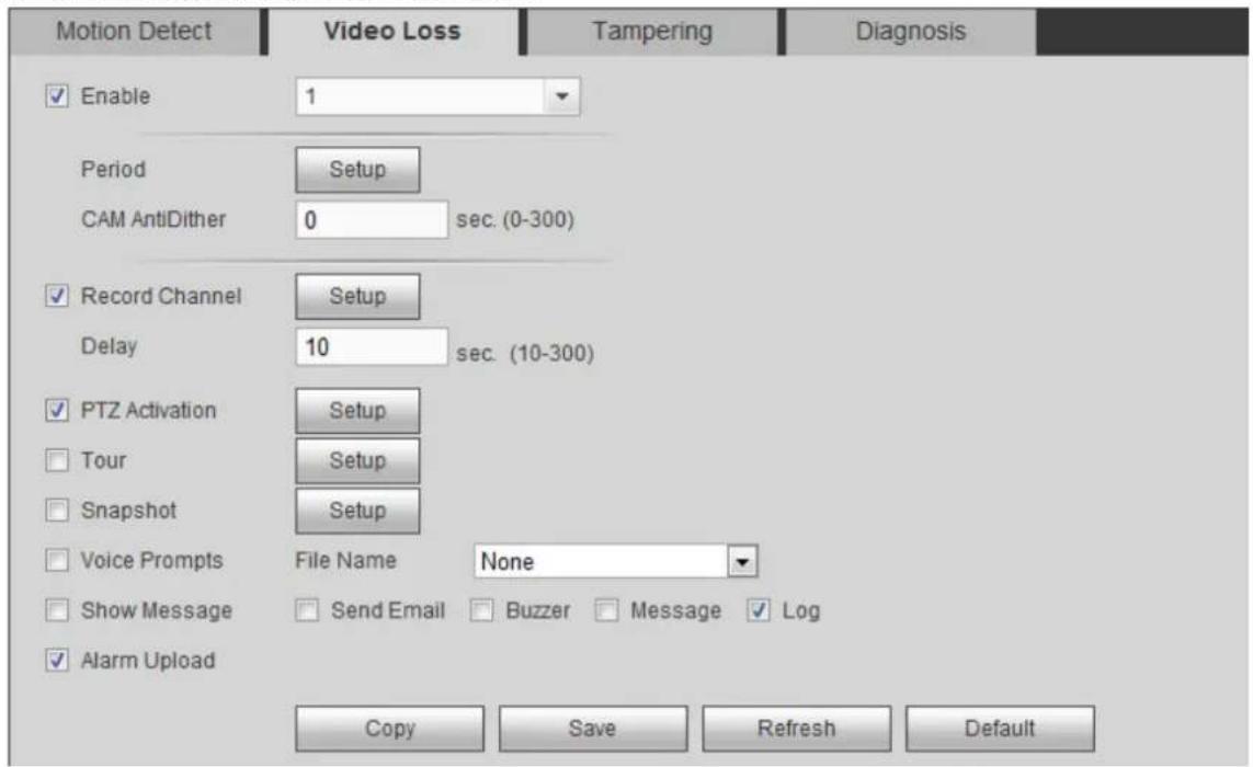
text_image
Motion Detect Video Loss Tampering Diagnosis Enable 1 Period Setup CAM AntiDither 0 sec. (0-300) Record Channel Setup Delay 10 sec. (10-300) PTZ Activation Setup Tour Setup Snapshot Setup Voice Prompts File Name None Show Message Send Email Buzzer Message Log Alarm Upload Copy Save Refresh DefaultFigure 5-53
Tampering
The tampering interface is shown as in Figure 5-54.
After analysis video, system can generate a tampering alarm when the detected moving signal reached the sensitivity you set here.
For detailed setups, please refer to motion detect for detailed information.

text_image
Motion Detect Video Loss Tampering Diagnosis Enable 1 Period Setup CAM AntiDither 0 sec. (0-300) Sensitivity 3 Record Channel Setup Delay 10 sec. (10-300) PTZ Activation Setup Tour Setup Snapshot Setup Voice Prompts File Name None Show Message Send Email Buzzer Message Log Alarm Upload Copy Save Refresh DefaultFigure 5-54
Diagnosis
System can trigger an alarm when the stripe, noise, color cast, out of focus, over exposure event occurred. See Figure 5-55.
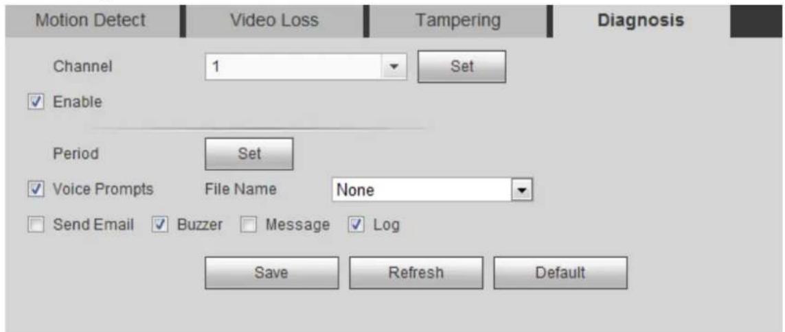
text_image
Motion Detect Video Loss Tampering Diagnosis Channel 1 Set Enable Period Set Voice Prompts File Name None Send Email Buzzer Message Log Save Refresh DefaultFigure 5-55
Click Set button, you can check the corresponding box to select diagnosis type. See Figure 5-56.

text_image
Diagnosis Stripe ✓ 30 Noise ✓ 30 Color Cast ✓ 30 Out of Focus ✓ 30 Overexposure ✓ 30 Save CancelFigure 5-56
Note
Video diagnosis alarm can trigger PTZ preset, tour, and pattern.
For detailed setups, please refer to motion detect for detailed information.
Alarm
Before operation, please make sure you have properly connected alarm devices such as buzzer.
The input mode includes local alarm and network alarm.
Local Alarm
The local alarm interface is shown as in Figure 5-57. It refers to alarm from the local device.
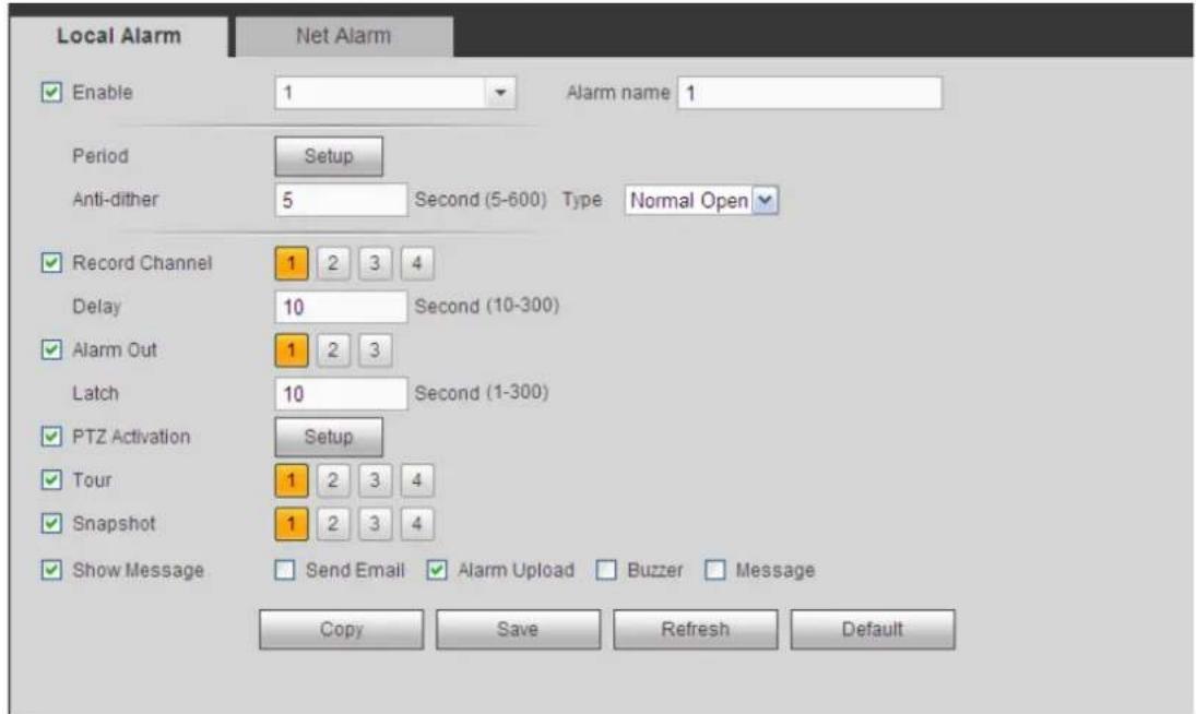
text_image
Local Alarm Enable 1 Alarm name 1 Period Setup Anti-dither 5 Second (5-600) Type Normal Open Record Channel 1 2 3 4 Delay 10 Second (10-300) Alarm Out 1 2 3 Latch 10 Second (1-300) PTZ Activation Setup Tour 1 2 3 4 Snapshot 1 2 3 4 Show Message Send Email Alarm Upload Buzzer Message Copy Save Refresh DefaultFigure 5-57

text_image
Setup Thursday Copy 00 : 00 - 24 : 00 00 : 00 - 24 : 00 00 : 00 - 24 : 00 00 : 00 - 24 : 00 00 : 00 - 24 : 00 00 : 00 - 24 : 00 00 : 00 - 24 : 00 Save CancelFigure 5-58
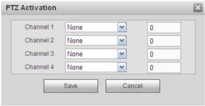
text_image
PTZ Activation Channel 1 None 0 Channel 2 None 0 Channel 3 None 0 Channel 4 None 0 Save CancelFigure 5-59
Please refer to the following sheet for detailed information.
| Parameter Function | |
| Enable | You need to check the box to enable this function.Please select a channel from the dropdown list. |
| Period | This function becomes activated in the specified periods.There are six periods in one day. Please draw a circle to enable corresponding period.Select date. If you do not select, current setup applies to today only. You can select all week column to apply to the whole week.Click OK button, system goes back to local alarm interface, please click save button to exit. |
| Anti-dither | System only memorizes one event during the anti-dither period. The value ranges from 5s to 600s. |
| Sensor type | There are two options: NO/NC. |
| Record channel | System auto activates motion detection channel(s) to record once an alarm occurs. Please note you need to set alarm record period and go to Storage-> Schedule to setcurrent channel as schedule record. |
| Record Delay | System can delay the record for specified time after alarm ended. The value ranges from 10s to 300s. |
| Alarm out | Enable alarm activation function. You need to select alarm output port so that system can activate corresponding alarm device when an alarm occurs. |
| Latch | System can delay the alarm output for specified time after an alarm ended. The value ranges from 1s to 300s. |
| Show message | System can pop up a message to alarm you in the local host screen if you enabled this function. |
| Buzzer | Check the box here to enable this function. The buzzer beeps when an alarm occurs. |
| Alarm upload | System can upload the alarm signal to the centre (Including alarm centre). |
| Send Email | If you enabled this function, System can send out an email to alert you when an alarm occurs. |
| Tour | You need to check the box here to enable this function. System begins 1-window or multiple-window tour display among the channel(s) you set to record when an alarm occurs. |
| PTZ Activation | Here you can set PTZ movement when alarm occurs. Such as go to preset X. |
Net Alarm
The network alarm interface is shown as in Figure 5-60.
Network alarm refers to the alarm signal from the network. System does not anti-dither and sensor type setup.
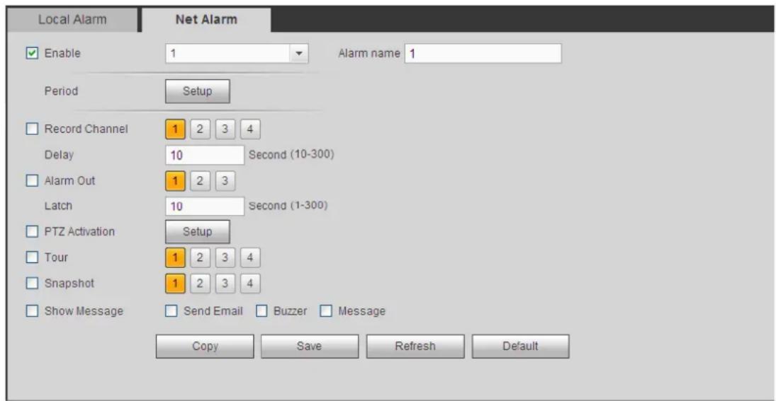
text_image
Local Alarm Enable 1 Alarm name 1 Period Setup Record Channel 1 2 3 4 Delay 10 Second (10-300) Alarm Out 1 2 3 Latch 10 Second (1-300) PTZ Activation Setup Tour 1 2 3 4 Snapshot 1 2 3 4 Show Message Send Email Buzzer Message Copy Save Refresh DefaultFigure 5-60
Abnormality
It includes three types: HDD/Network/User. See Figure 5-61 and Figure 5-63.
- HDD includes: No disk, disk error, disk no space.
● Network includes net disconnection, IP conflict, and MAC conflict. - User: It includes illegal login.

text_image
HDD Event Type No HDD Enable Voice Prompts File Name None Show Message Send Email Buzzer Message Log Alarm Upload Save RefreshFigure 5-61

text_image
HDD Event Type Disconnect Enable Voice Prompts File Name None Show Message Send Email Buzzer Message Log Record Channel Setup Delay 10 sec. (10-300) Save RefreshFigure 5-62
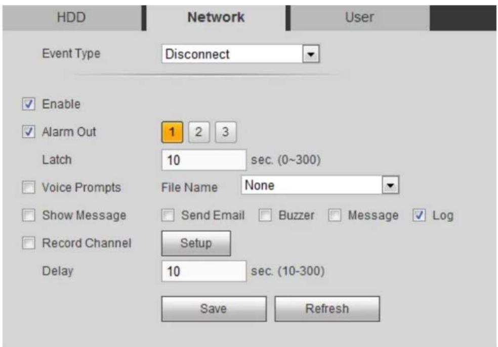
text_image
HDD Event Type Disconnect Enable Alarm Out 1 2 3 Latch 10 sec. (0~300) Voice Prompts File Name None Show Message Send Email Buzzer Message Log Record Channel Setup Delay 10 sec. (10-300) Save RefreshFigure 5-63
Please refer to the following sheet for detailed information.
| Parameter | Function |
| Event Type | The abnormal events include: No disk, disk error, disk no space, net disconnection, IP conflict and MAC conflict.You can set one or more items here.Less than: You can set the minimum percentage value here (For disk not space only). The device can alarm when capacity is not sufficient.You need to draw a circle to enable this function. |
| Enable | Check the box here to enable selected function. |
| Alarm Out | Please select corresponding alarm output channel when an alarm occurs. You need to check the box to enable this function. |
| Latch | The alarm output can delay for the specified time after an alarm stops. Th value ranges from 0s to 300s. The default setup is 10 seconds. The o second means there is no delaying time. |
| Attempt(s) | It is to set login attempt times. Once the login attempt exceeds the threshold you set here, current account will be locked. This function is illegal login only. |
| Lock time | It is to set account lock time once its login attempt has exceeded the threshold you set. This function is for illegal login only. |
| Show message | System can pop up a message to alarm you in the local host screen if you enabled this function. |
| Alarm upload | System can upload the alarm signal to the centre (Including alarm centre. |
| Send Email | If you enabled this function, System can send out an email to alert you when an alarm occurs. |
| Buzzer | Check the box here to enable this function. The buzzer beeps when an alarm occurs. |
| Log | Check the box here, system can record the network event alarm log. |
Storage
Schedule
In this interfaces, you can add or remove the schedule record/snapshot setup. See Figure 5-64.
There are three record modes: general (auto), motion detect and alarm. There are six periods in one day. You can view the current time period setup from the color bar.
● Green color stands for the general record/snapshot.
● Yellow color stands for the motion detect record/snapshot..
● Red color stands for the alarm record/snapshot.
● Blue color stands for MD&alarm record/snapshot.
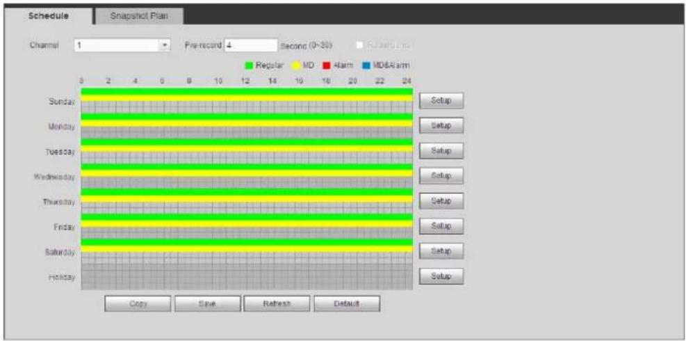
text_image
Schedule Snapshot Plan Channel 1 Pre-record 4 Second (0~30) Regular Regular MD Alarm MD&Alarm Sunday Setup Monday Setup Tuesday Setup Wednesday Setup Thursday Setup Friday Setup Saturday Setup Holiday Setup Copy Save Refresh DefaultFigure 5-64
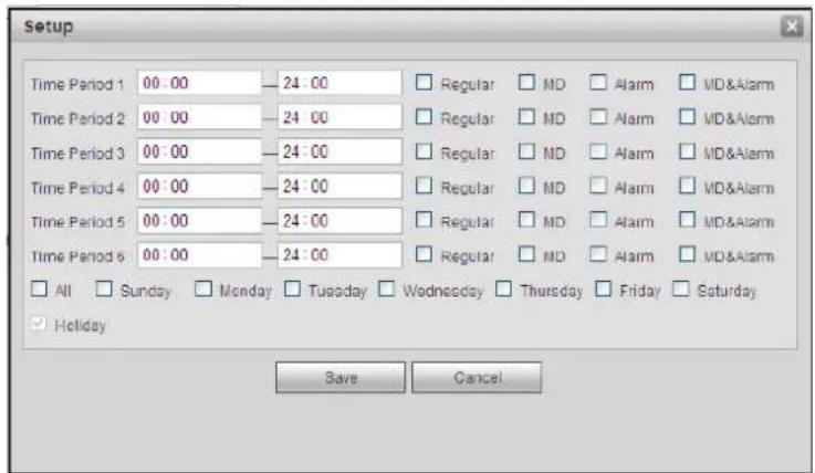
text_image
Setup Time Period 1 00:00 — 24:00 Regular MD Alarm MD&Alarm Time Period 2 00:00 — 24:00 Regular MD Alarm MD&Alarm Time Period 3 00:00 — 24:00 Regular MD Alarm MD&Alarm Time Period 4 00:00 — 24:00 Regular MD Alarm MD&Alarm Time Period 5 00:00 — 24:00 Regular MD Alarm MD&Alarm Time Period 6 00:00 — 24:00 Regular MD Alarm MD&Alarm All Sunday Monday Tuesday Wednesday Thursday Friday Saturday Holiday Save CancelFigure 5-65

text_image
All Channel 1 Channel 2 Channel 3 Channel 4 Save CancelFigure 5-66
Please refer to the following sheet for detailed information.
| Parameter | Function |
| Channel | Please select a channel from the dropdown list. |
| Pre-record | Please input pre-record time here. The value ranges from 0 to 30. |
| Redundancy | Check the box here to enable redundancy function. Please note this function is null if there is only one HDD. |
| Snapshot | Check the box here to enable snapshot function. |
| Holiday | Check the box here to enable holiday function. |
| Setup (Sunday to Saturday) | Click the Setup button, you can set record period. See Figure 5-65. There are six periods in one day. If you do not check the date at the bottom of the interface, current setup is for today only.Please click Save button and then exit. |
| Setup (Holiday) | Click the Setup button, you can set record period. See Figure 5-65. There are six periods in one day. If you check Holiday box, current channel shall record as your holiday setup here. |
| Copy | Copy function allows you to copy one channel setup to another. After setting in channel, click Copy button, you can go to interface Figure 5-66. You can see current channel name is grey such as channel 1. Now you can select the channel you want to paste such as channel 5/6/7. If you want to save current setup of channel 1 to all channels, you can click the first box “ALL”. Click the OK button to save current copy setup. Click the OK button in the Encode interface, the copy function succeeded. |
Local Storage
The local interface is shown as in Figure 5-67. Here you can see HDD information. You can also operate the read-only, read-write, redundancy (if there are more than on HDD) and format operation.
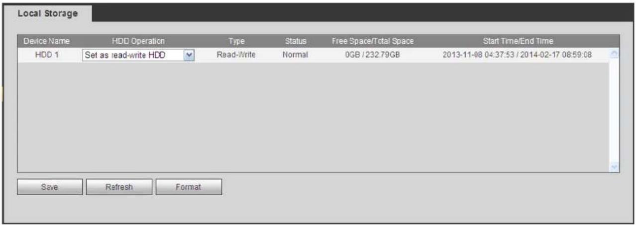
text_image
Local Storage Device Name HD Operation Type Status.Free Space/Total Space Start Time/End Time HDD 1 Set as read-write HDD Read-Write Normal 0GB / 232.79GB 2013-11-08 04:37:53 / 2014-02-17 08:59:08 Save Refresh FormatFigure 5-67
Record
The interface is shown as in Figure 5-68.

text_image
Record Main Stream All 1 2 3 4 Schedule Manual Stop Sub Stream Schedule Manual Stop Snapshot Open Stop Save RefreshFigure 5-68
Please refer to the following sheet for detailed information.
| Parameter | Function |
| Channel | Here you can view channel number.The number displayed here is the max channel amount of your device. |
| Status | There are three statuses: schedule, manual and stop. |
| Schedule | System enables auto record function as you set in record schedule setup (general, motion detect and alarm). |
| Manual | It has the highest priority.Enable corresponding channel to record no matter what period applied in the record setup. |
| Stop | Stop current channel record no matter what period applied in the record setup. |
| Start all/stop all | Check the corresponding All button, you can enable or disable all channels record. |
Setting
General
The general interface includes general, date/time and holiday setup.
General
The general interface is shown as in Figure 5-69.

text_image
General Date&Time Holiday Device ID HCVR Device No. 8 Language ENGLISH Video Standard PAL HDD Full Overwrite Pack Duration 60 Minute Auto Logout 10 Minute (0-60) Startup Wizard ✓ Navigation Bar ✓ Save Refresh DefaultFigure 5-69
Please refer to the following sheet for detailed information.
| Parameter | Function |
| Device ID | It is to set device name. |
| Device No. | It is device channel number. |
| Language | You can select the language from the dropdown list.Please note the device needs to reboot to get the modification activated. |
| Video Standard | This is to display video standard such as PAL. |
| HDD full | Here is for you to select working mode when hard disk is full. There are two options: stop recording or rewrite. If current working HDD is overwritten or the current HDD is full while the next HDD is no empty, then system stops recording, If the current HDD is full and then next HDD is not empty, then system overwrites the previous files. |
| Pack duration | Here is for you to specify record duration. The value ranges from 1 to 120 minutes. Default value is 60 minutes. |
Date and time
The date and time interface is shown as in Figure 5-70
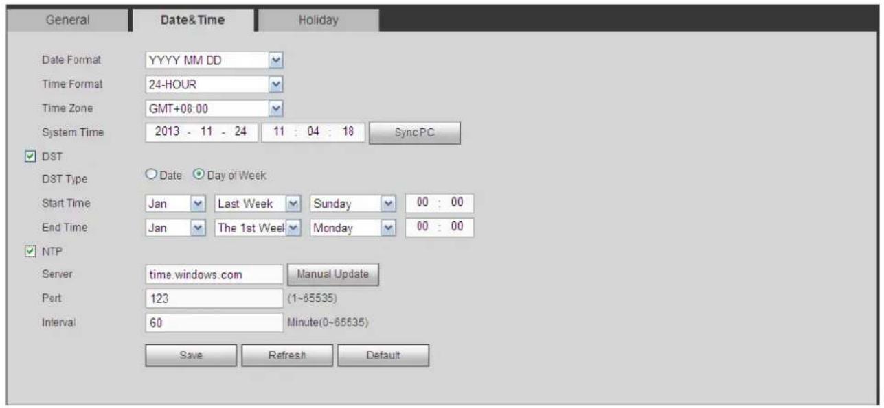
text_image
General Date&Time Holiday Date Format YYYY MM DD Time Format 24-HOUR Time Zone GMT+08.00 System Time 2013 - 11 - 24 11 : 04 : 18 SyncPC ✓ DST DST Type ○ Date ○ Day of Week Start Time Jan ▼ Last Week ▼ Sunday ▼ 00 : 00 End Time Jan ▼ The 1st Week ▼ Monday ▼ 00 : 00 ✓ NTP Server time.windows.com Manual Update Port 123 (1~65535) Interval 60 Minute(0~65535) Save Refresh DefaultFigure 5-70
Please refer to the following sheet for detailed information.
| Parameter Function | |
| Date format | Here you can select date format from the dropdown list. |
| Time Format | There are two options: 24-H and 12-H. |
| Time zone | The time zone of the device. |
| System time | It is to set system time. It becomes valid after you set. |
| Sync PC | You can click this button to save the system time as your PC current time. |
| DST | Here you can set day night save time begin time and end time. You can set according to the date format or according to the week format. |
| NTP | You can check the box to enable NTP function. |
| NTP server | You can set the time server address. |
| Port | It is to set the time server port. |
| Interval | It is to set the sync periods between the device and the time server. |
Holiday Setup
Holiday setup interface is shown as in Figure 5-71.
Here you can click Add box to add a new holiday and then click Save button to save.
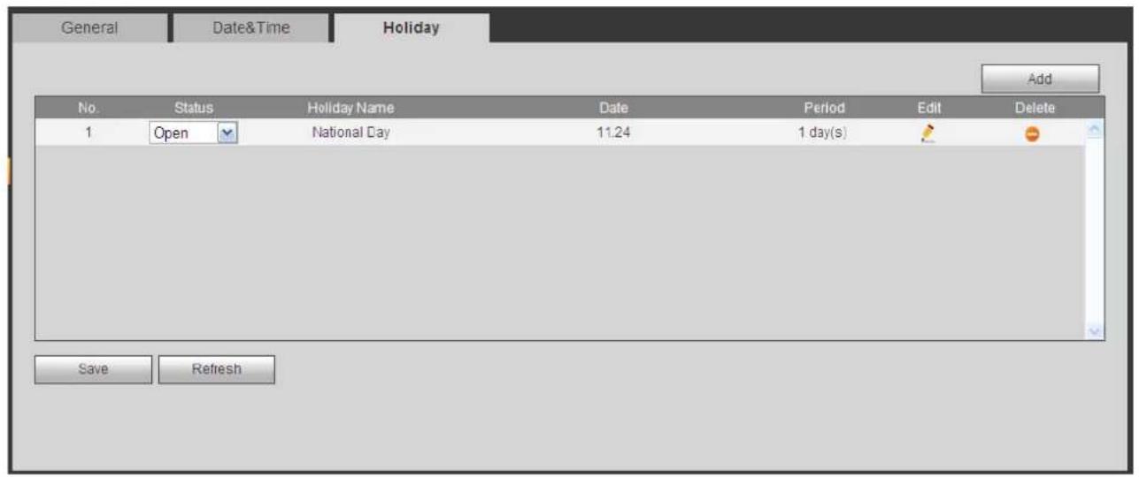
text_image
General Date&Time Holiday Add No. Status Holiday Name Date Period Edit Delete 1 Open National Day 11:24 1 day(s) Save RefreshFigure 5-71
Display
Display interface includes GUI, TV adjust, Tour and zero-channel encoding.
Display
Here you can set background color and transparency level. See Figure 5-72.

text_image
Display Tour Zero Channel Resolution 1280*1024 Transparency 0% Time Display ✓ Channel Display ✓ Image Enhance ✓ Save Refresh DefaultFigure 5-72
Please refer to the following sheet for detailed information.
| Parameter Function | |
| Resolution | There are four options:1920×1080,1280×1024(default),1280×720,1024×768. Please note the system needs to reboot to activate current setup. |
| Transparency | Here is for you to adjust transparency. The value ranges from 128 to 255. |
| Time title/channel title | Check the box here, you can view system time and channel number on the monitor video. |
| Image enhance | Check the box; you can optimize the margin of the preview video. |
Tour
The tour interface is shown as in Figure 5-73. Here you can set tour interval, split mode, motion detect tour and alarm tour mode.
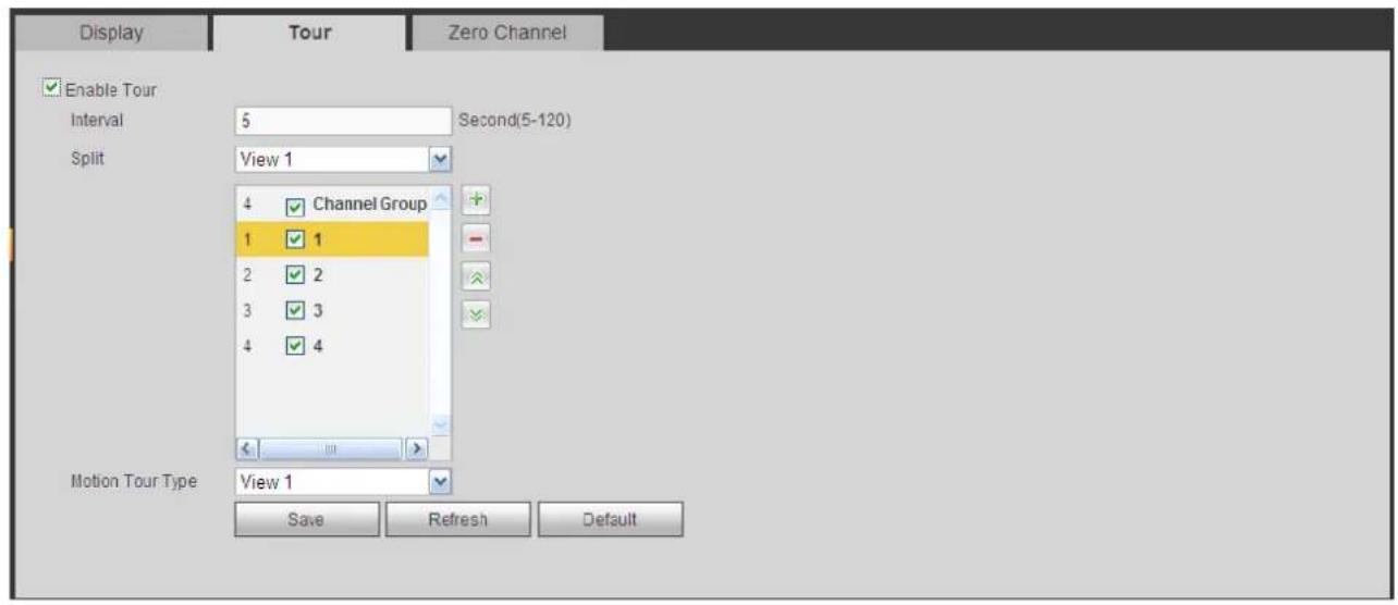
text_image
Display Tour Zero Channel Enable Tour Interval 5 Second(5-120) Split View 1 4 Channel Group 1 1 2 2 3 3 4 4 Motion Tour Type View 1 Save Refresh DefaultFigure 5-73
Please refer to the following sheet for detailed information.
| Parameter Function | |
| Enable tour | Check the box here to enable tour function. |
| Interval | Here is for you to adjust transparency. The value ranges from 5 to 120s. The default setup is 5s. |
| Split | Here you can set window mode and channel group. System can support 1/4/8-window according to device channel amount. |
| Motion tour/Alarm tour | Here you can set motion detect tour/alarm tour window mode. System supports 1/8-window now. |
Zero Channel
The zero-channel interface is shown as in Figure 5-74. Here you can enable zero-channel function and set corresponding information.

text_image
Display Tour Zero Channel Enable Compression H 264 Resolution CIF Frame Rate 25 Bit Rate 1024 Kb/S Save Refresh DefaultFigure 5-74
Please refer to the following sheet for detailed information.
| Parameter Function | |
| Enable | Check the box here to enable zero-channel function. |
| Compression | System supports H.264. |
| Resolution | Please select from the dropdown list. System supports D1/CIF/QCIF and etc. |
| Frame rate | Please select from the dropdown list. The value ranges from 1-25(PAL) or 1-30(NTSC). |
| Bit rate | Please select from the dropdown list. |
Video Matrix
The interface is shown as in Figure 5-75.
Here you can set video output channel and interval.

text_image
BNC Enable Interval 5 sec.(5-120) Resolution 1280*720 Window Split View 1 14 Channel Group 1 1 2 2 3 3 4 4 5 5 6 6 Save Refresh DefaultFigure 5-75
| Parameter Function | |
| Enable | Check the box here to enable this function. |
| Interval | It is to set the interval from current channel group to the next channel group. |
| Window split | Support 1-window split only. |
| Delete | Select a channel group and then clickto delete it. |
| Up/Down | Clickorto adjust channel tour sequence. |
Add channel group
Click +, you can see system pops up the following dialogue box. See Figure 5-76. Please select the channels and then click OK button.

text_image
Add Channel Group 1 2 3 4 5 6 7 8 9 10 11 12 13 14 15 16 Save CancelFigure 5-76
Delete channel group
Select a channel group and then click - ,you can delete it.
Modify channel group
Select a channel group and then double click, you can see the following interface. See Figure 5-77. You can change the setup and then click OK button.

text_image
Modify Channel Group 1 2 3 4 5 6 7 8 9 10 11 12 13 14 15 16 Save CancelFigure 5-77
PTZ
The PTZ interface is shown as in Figure 5-78.
Before setup, please check the following connections are right:
- PTZ and decoder connection is right. Decoder address setup is right.
● Decoder A (B) line connects with DVR A (B) line.
Click Save button after you complete setup, you can go back to the monitor interface to control speed dome.
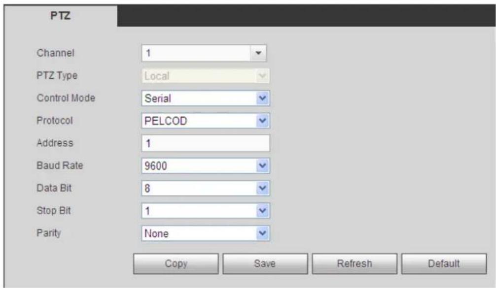
text_image
PTZ Channel 1 PTZ Type Local Control Mode Serial Protocol PELCOD Address 1 Baud Rate 9600 Data Bit 8 Stop Bit 1 Parity None Copy Save Refresh DefaultFigure 5-78
Please refer to the following sheet for detailed information.
| Parameter | Function |
| Channel | Select speed dome connected channel. |
| PTZ type | There are two options: local/remote. |
| Control mode | You can select control mode from the dropdown list. There are two options: Serial/HDUTC. For Holis series product, please select HDUTC. The control signal is sent to the PTZ via the coaxial cable. For the serial mode, the control signal is sent to the PTZ via the RS485 port. |
| Protocol | Please select corresponding protocol from the dropdown list. |
| Address | Set corresponding dome address. Default value is 1. Please note your setup here shall comply with your dome address; otherwise you can not control the speed dome. |
| Baud Rate | Select the dome baud rate. Default setup is 9600. |
| Data Bit | Default setup is 8. Please set according to the speed dome dial switch setup. |
| Stop bit | Default setup is 1. Please set according to the speed dome dial switch setup. |
| Parity | Default setup is none. Please set according to the speed dome dial switch setup. |
ATM/POS
The ATM/POS function is for financial areas. It includes Sniffer, information analysis and title overlay function. The Sniffer mode is network.
The network type interface is shown as below. See Figure 5-79.
Here we take the ATM/POS protocol to continue.
There are two types: with or without the protocol according to client's requirements.
With the protocol
For ATM/POS with the protocol, you just need to set the source IP, destination IP (sometimes you need to input corresponding port number).
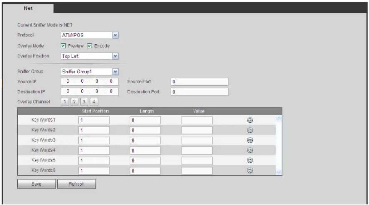
text_image
Net Current Sniffer Mode is NET Protocol ATM/POS Overlay Mode Preview Encode Overlay Position Top Left Sniffer Group Sniffer Group1 Source IP 0 . 0 . 0 . 0 Source Port 0 Destination IP 0 . 0 . 0 . 0 Destination Port 0 Overlay Channel 1 2 3 4 Start Position Length Value Key Words1 1 0 Key Words2 1 0 Key Words3 1 0 Key Words4 1 0 Key Words5 1 0 Key Words6 1 0 Save RefreshFigure 5-79
Without the protocol
For the ATM/POS without the protocol, the interface is shown as in Figure 5-80.
Source IP refers to host IP address that sends out information (usually it is the device host.)
Destination IP refers to other systems that receive information.
Usually you do not need to set source port and target port.
There are total four groups IP. The record channel applies to one group (optional) only.
Six frame ID groups verification can guarantee information validity and legal.
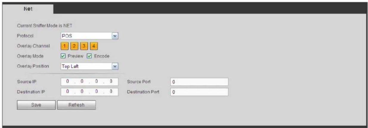
text_image
Net Current Sniffer Mode is NET Protocol POS Overlay Channel 1 2 3 4 Overlay Mode Preview Encode Overlay Position Top Left Source IP 0.0.0.0 Source Port 0 Destination IP 0.0.0.0 Destination Port 0 Save RefreshFigure 5-80
Account
Note:
- For the character in the following user name or the user group name, system max supports 6-digits. The space in the front or at the end of the string is null. The valid string includes: character, number, and underline.
- The user amount default setup is 64 and the group amount default setup is 20. The factory default setup includes two levels: user and admin. You can set the corresponding group and then set the rights for the respective user in the specified groups.
- User management adopts group/user modes. The user name and the group name shall be unique. One user shall be included in only one group.
User name
In this interface you can add/remove user and modify user name. See Figure 5-81.
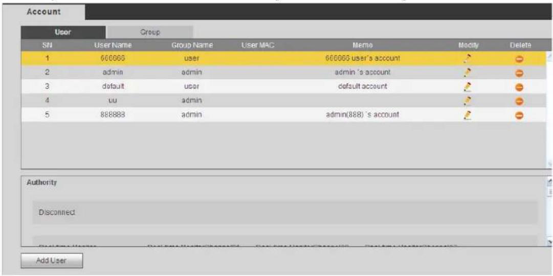
text_image
Account User Group SN User Name Group Name User MAC Memo Modify Delete 1 666665 user 666665 user's account 2 admin admin admin's account 3 default user default account 4 uu admin 3 5 888888 admin admin(888) 's account Authority Disconnect Add UserFigure 5-81
Add user: It is to add a name to group and set the user rights. See Figure 5-82.
There are three default users: admin and hidden user "default".
Hidden user "default" is for system interior use only and can not be deleted. When there is no login user, hidden user "default" automatically login. You can set some rights such as monitor for this user so that you can view some channel view without login.
Here you can input the user name and password and then select one group for current user.
Please note the user rights shall not exceed the group right setup.
For convenient setup, please make sure the general user has the lower rights setup than the admin.

text_image
Add User User Name Reusable Password Confirm Password Group admin User MAC : : : : : Memo Authority System Manager Playback Monitor All Account System Disconnect user Default&Update PTZ Control System Info Manual Control File Backup Color Setting Storage Event Network CAMERA Clear Log Shutdown Save CancelFigure 5-82
Modify user
It is to modify the user property, belonging group, password and rights. See Figure 5-83.
Modify password
It is to modify the user password. You need to input the old password and then input the new password twice to confirm the new setup. Please click the OK button to save.
Please note, the password ranges from 1-digit to 6-digit. It shall include the number only. For the user of the account rights, he can modify the password of other users.
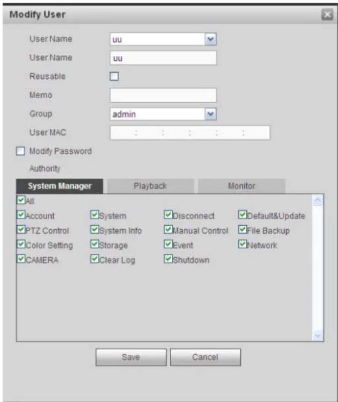
text_image
Modify User User Name uu User Name uu Reusable Memo Group admin User MAC : : : : : : Modify Password Authority System Manager Playback Monitor All Account System Disconnect Default&Update PTZ Control System Info Manual Control File Backup Color Setting Storage Event Network CAMERA Clear Log Shutdown Save CancelFigure 5-83
Group
The group management interface can add/remove group, modify group password and etc. The interface is shown as in Figure 5-84.

text_image
Account User Group SN Group Name Memo Modify Delete 1 admin administrator group 2 user user group Authority Shutdown Manual Control File Backup Storage PTZ Control Account System info Clear Log Default&Update System CAMERA Network Add GroupFigure 5-84
Add group: It is to add group and set its corresponding rights. See Figure 5-85. Please input the group name and then check the box to select the corresponding rights. It includes: shutdown/reboot device, live view, record control, PTZ control and etc.
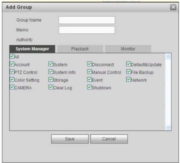
text_image
Add Group Group Name Memo Authority System Manager Playback Monitor All Account PTZ Control Color Setting CAMERA System System Info Storage Clear Log Disconnect Manual Control Event Shutdown Default&Update File Backup Network Save CancelFigure 5-85
Modify group
Click the modify group button, you can see an interface is shown as in Figure 5-86. Here you can modify group information such as remarks and rights.

text_image
Modify Group Group Name user Group Name user Memo user group Authority System Manager Playback Monitor All Account System Disconnect Default&Update PTZ Control System Info Manual Control File Backup Color Setting Storage Event Network CAMERA Clear Log Shutdown Save CancelFigure 5-86
Auto maintain
The auto maintain interface is shown as in Figure 5-87.
Here you can select auto reboot and auto delete old files interval from the dropdown list.
If you want to use the auto delete old files function, you need to set the file period.
Click Manual reboot button, you can restart device manually.
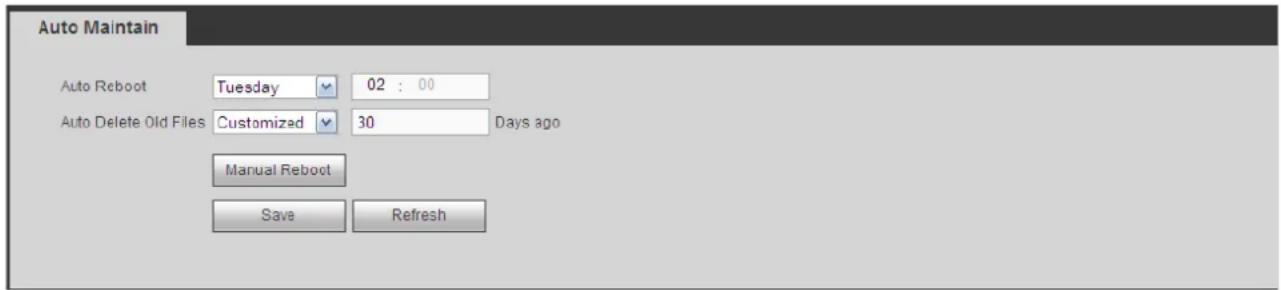
text_image
Auto Maintain Auto Reboot Tuesday 02 : 00 Auto Delete Old Files Customized 30 Days ago Manual Reboot Save RefreshFigure 5-87
Import/Export
The interface is shown as in Figure 5-88.

text_image
Import&Export Config Import Config ExportFigure 5-88
Please refer to the following sheet for detailed information.
| Parameter | Function |
| Import | It is to import the local setup files to the system. |
| Export | It is to export the corresponding WEB setup to your local PC. |
Default
The default setup interface is shown as in Figure 5-89.
Here you can select Channel/Network/Event/Storage/System. Or you can check the All box to select all items.

text_image
Default ✓ Select All ✓ CAMERA ✓ NETWORK ✓ EVENT ✓ STORAGE ✓ SYSTEM Default Factory DefaultFigure 5-89
Upgrade
The upgrade interface is shown as in Figure 5-90.
Please select the upgrade file and then click the update button to begin update. Please note the file name shall be as *.bin. During the upgrade process, do not unplug the power cable, network cable, or shutdown the device.
NOTE:
Improper upgrade program may result in device malfunction!
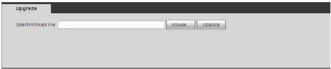
text_image
Upgrade Select Firmware File Browse... UpgradeFigure 5-90
Information
Version
The version interface is shown as in Figure 5-91.
Here you can view record channel, alarm input/output information, software version, release date and etc. Please note the following information is for reference only.
| Version | |
| Record Channel: | 4 |
| Alarm In: | 0 |
| Alarm Out: | 0 |
| SN: | FA3KP043D03832 |
| System Version: | 3.200.0005 1, Build Date: 2014-01-26 |
Figure 5-91
Log
Here you can view system log. See Figure 5-92.
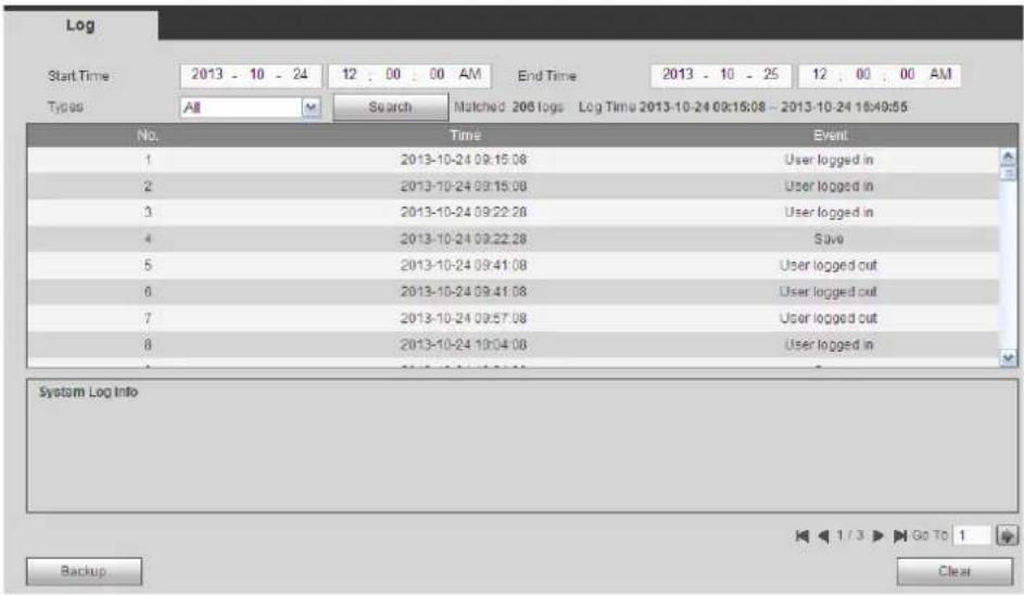
text_image
Log Start Time 2013 - 10 - 24 12 : 00 : 00 AM End Time 2013 - 10 - 25 12 : 00 : 00 AM Types All Search Matched: 206 logs Log Time 2013-10-24 09:16:08 - 2013-10-24 16:40:55 No. Time Event 1 2013-10-24 09:15:08 User logged in 2 2013-10-24 09:15:08 User logged in 3 2013-10-24 09:22:28 User logged in 4 2013-10-24 09:22:28 Save 5 2013-10-24 09:41:08 User logged out 6 2013-10-24 09:41:08 User logged out 7 2013-10-24 09:57:08 User logged out 8 2013-10-24 10:04:08 User logged in System Log Info Backup ClearFigure 5-92
Please refer to the following sheet for log parameter information.
| Parameter | Function |
| Type | Log types include: system operation, configuration operation, data operation, event operation, record operation, user management, log clear. |
| Start time | Set the start time of the requested log. |
| End time | Set the end time of the requested log. |
| Search | You can select log type from the drop down list and then click search button to view the list.You can click the stop button to terminate current search operation. |
| Detailed information | You can select one item to view the detailed information. |
| Clear | You can click this button to delete all displayed log files. Please note system does not support clear by type. |
| Backup | You can click this button to backup log files to current PC. |
Online User
The online user interface is shown as in Figure 5-93.
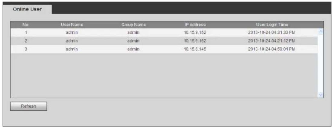
text_image
Online User No User Name Group Name IP Address User Login Time 1 admin admin 10.15.9.152 2013-10-24 04:31:33 PM 2 admin admin 10.15.9.152 2013-10-24 04:21:12 PM 3 admin admin 10.15.6.145 2013-10-24 04:50:01 PM RefreshFigure 5-93
HDD
The HDD interface is shown as in Figure 5-94. Here you can view HDD information.
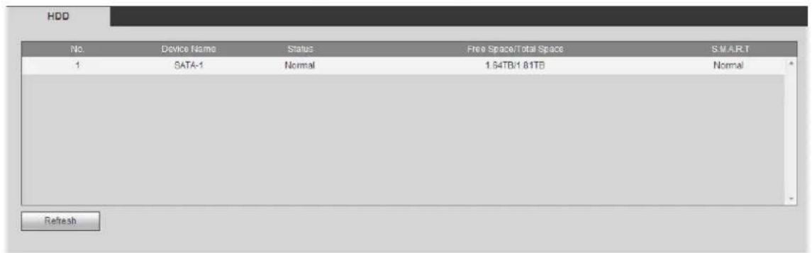
text_image
HDD No. Device Name Status Free Space/Total Space SMART 1 SATA-1 Normal 1.64TB/1.81TB Normal RefreshFigure 5-94
Playback
Click Playback button, you can see an interface is shown as in Figure 5-95.

text_image
WEB SERVICE PREVIEW PLAYBACK ALARM SETUP INFO. LOGOUT 1 2016 Sun Mon Tue Wed/Thu Fri Sat 3 4 5 6 7 8 9 10 11 12 13 14 15 16 17 18 19 20 21 22 23 5s 5s 5s 5s 5s 5s 5s 31 1 2 3 4 File List Stop Sync AI Regular MD Alarm CardFigure 5-95
Search Record
Please set record type, record date, window display mode and channel name.
- Select Date
You can click the date on the right pane to select the date. The green highlighted date is system current date and the blue highlighted date means it has record files.
- Window Split
Select window split mode. Click 📄 to display in full screen. Click ESC button to exit. See Figure 5-96.
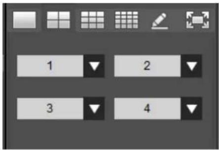
text_image
1 2 3 4Figure 5-96
- Customized playback
Click, you can see the following interface. See Figure 5-97.
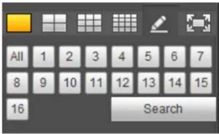
text_image
All 1 2 3 4 5 6 7 8 9 10 11 12 13 14 15 16 SearchFigure 5-97
Now you can select one or more channel(s) and then click ____ to search record(s).
System supports one or more channels. The window split mode can auto adjust according to the channel amount. System max supports 16-split.
Click k All button to select all channels at the same time.
Click ▶, system begins playback.
- Select Channel
1\~n(n depends on your product channel amount) means main stream and A1\~An ((n depends on your product channel amount)) means sub stream.
- Select Record Type
Check the corresponding box to select record type. See Figure 5-98.

text_image
All Regular MD Alarm CardFigure 5-98
File List
Click File list button, you can see the corresponding file(s) in the list. See Figure 5-99.
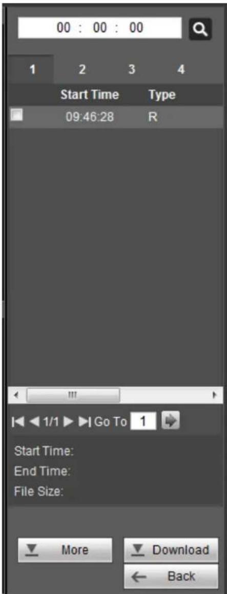
text_image
00 : 00 : 00 1 2 3 4 Start Time Type 09:46:28 R Start Time: End Time: File Size: More Download BackFigure 5-99
Playback
Select a file you want to play and then click Play button, system can begin playback. You can select to playback in full-screen. Please note for one channel, system can not playback and download at the same time. You can use the playback control bar to implement various operations such as play, pause, stop, slow play, fast play and etc.
Download
Select the file(s) you want to download and then click download button, you can see an interface shown as in Figure 5-100. The Download button becomes Stop button and there is a process bar for your reference. Please go to you default file saved path to view the files.
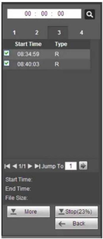
text_image
00 : 00 : 00 1 2 3 4 Start Time Type ✓ 08:34:59 R ✓ 08:40:03 R Start Time: End Time: File Size: More Stop(23%) ← BackFigure 5-100
Load more
It is for you to search record or picture. You can select record channel, record type and record time to download. Or you can use watermark function to verify file.
Download By File
Select channel, record type, bit stream type and then input start time and end time. Click Search button, the download by file interface is shown as in Figure 5-101.
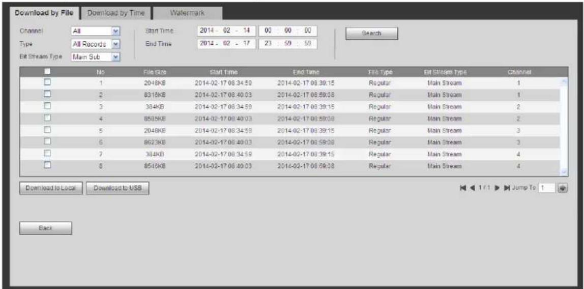
text_image
Download by File Download by Time Wafermark Channel All Start Time 2014 - 02 - 14 00 : 00 : 00 Type All Records End Time 2014 - 02 - 17 23 : 59 : 59 Search Bit Stream Type Main Sub No File Size Start Time End Time File Type Bit Stream Type Channel 1 2048KB 2014-02-17 06:34:59 2014-02-17 06:39:15 Regular Main Stream 1 2 8315KB 2014-02-17 06:40:03 2014-02-17 06:59:08 Regular Main Stream 1 3 384KB 2014-02-17 06:34:59 2014-02-17 06:39:15 Regular Main Stream 2 4 8585KB 2014-02-17 06:40:03 2014-02-17 06:59:08 Regular Main Stream 2 5 2048KB 2014-02-17 06:34:59 2014-02-17 06:39:15 Regular Main Stream 3 6 8623KB 2014-02-17 06:40:03 2014-02-17 06:59:08 Regular Main Stream 3 7 384KB 2014-02-17 06:34:59 2014-02-17 06:39:15 Regular Main Stream 4 8 8585KB 2014-02-17 06:40:03 2014-02-17 06:59:08 Regular Main Stream 4 Download to Local Download to US$ Jump To 1 BackFigure 5-101
Holis HD Series DVR User Manual 4, 8 & 16 Channel Models
Check the file(s) you want to download and there are two options for you to save the file(s).
- Download to local
Click Download to local, system pops up the following interface for you to set record format and saved path. See Figure 5-102.

text_image
Record Format: DAV Save Path: C:\RecordDownload\ Browse OK CancelFigure 5-102
You can click OK to download and view the download process. After the download operation, you can see corresponding dialog box.
- Download to USB
Connect the corresponding p peripheral device, and then click Download to USB button, you can see the following interface. See Figure 5-103.

text_image
Download by File Download by Time Watermark Channel: All Type: All Records Bit Stream Type: Main Sub Start Time 2014-02-14 00:00:00 End Time 2014-02-17 23:59:59 Search No File Size Start Time End Time File Type Bit Stream Type Channel 1 204KB 2014-02-17 06:34:59 2014-02-17 08:39:15 Regular Main Stream 1 2 831KB 2014-02-17 08:40:03 2014-02-17 08:59:08 Regular Main Stream 1 3 38KB 2014-02-17 08:34:59 2014-02-17 08:39:15 Regular Main Stream 2 4 85KB 2014-02-17 08:43:03 2014-02-17 08:59:08 Regular Main Stream 2 5 204KB 2014-02-17 08:34:59 2014-02-17 08:39:15 Regular Main Stream 3 6 862KB 2014-02-17 08:40:03 2014-02-17 08:59:08 Regular Main Stream 3 7 38KB 2014-02-17 08:34:59 2014-02-17 08:39:15 Regular Main Stream 4 8 854KB 2014-02-17 08:43:03 2014-02-17 08:59:08 Regular Main Stream 4 Download to Local Download to USB Backup Device :sub1(USB DISK) Search Backup type :DAV startBackup Name Markup type BUI Free Space(KU) Total space(KU) Directory sdb1(USB DISK) DISK USB 13682928 15136816 /varisdb1 BackFigure 5-103
Select Backup device and backup type first and then click Start backup button.
After the download operation, you can see corresponding dialogue box.
Download by Time
Select channel, bit stream type, start time and end time.
Click Download to Local button, you can see download by time interface is shown as in Figure 5-104.

text_image
Download by File Download by Time Watermark Channel 1 Start Time 2014 - 02 - 14 00 : 00 : 00 Bit Stream Type Main Stream End Time 2014 - 02 - 17 23 : 59 : 59 Download to Local Record Format: DAV Save Path: C:\RecordDownload Browse OK Cancel BackFigure 5-104
Set record format and saved path, you can click OK to download and view the download process. After the download operation, you can see corresponding dialog box.
Watermark
Watermark interface is shown as In Figure 5-105. Please select a file and then click Verify button to see the file has been tampered with or not
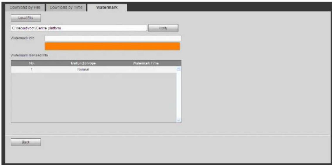
text_image
Download by File Download by Time Watermark Local Files C:\recordvoot\Centre platform Watermark Info Watermark Revised Info No Malfunction type Watermark Time 1 Normal BackFigure 5-105
Alarm
Click alarm function, you can see an interface is shown as Figure 5-106.
Here you can set device alarm type and alarm sound setup (Please make sure you have enabled audio function of corresponding alarm events.).

text_image
WEB SERVICE Live Playback Alarm Setup Info Logout No Time Alarm Type Alarm Channel Alarm Type Motion Detect Tampering HDD Error Video Loss HDD Full Operation Prompt Alarm Sound Play Alarm Sound Sound Path SelectFigure 5-106
Please refer to the following sheet for detailed information.
| Type | Parameter | Function |
| Alarm Type | Video loss | System alarms when video loss occurs. |
| Motion detection | System alarms when motion detection alarm occurs. | |
| Tampering | System alarms when camera is viciously masking. | |
| Disk full | System alarms when disk is full. | |
| Disk error | System alarms when disk error occurs. | |
| External alarm | Alarm input device sends out alarm. | |
| Operation | Prompt | Check the box here, system can automatically pops up an alarm icon on the Alarm button in the main interface when there is an alarm. |
| Alarm Sound | Play alarm sound | System sends out alarm sound when an alarm occurs. You can specify as you wish. |
| Sound path | Here you can specify alarm sound file. |
Log out
Click log out button, system goes back to log in interface. See Figure 5-107.
You need to input user name and password to login again.
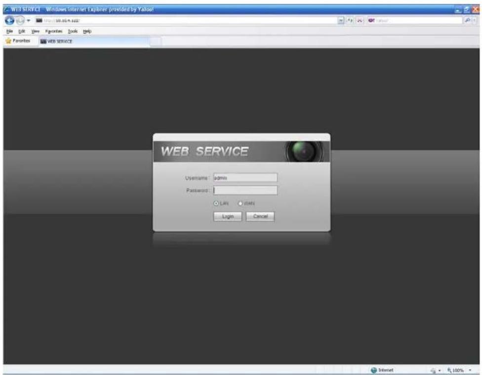
text_image
WEB SERVICE - Windows Internet Explorer provided by Yahoo! File Edit View Favorites Tools Help Favorites WEB SERVICE WEB SERVICE Username: admin Password: Lift WNT Login Cancel Internet 100%Figure 5-107
Un-install Web Control
You can use web un-install tool "uninstall web.bat" to un-install web control.
Note:
Before you un-installation, please close all web pages, otherwise the un-installation might result in error.
1. DVR can not boot up properly.
There are following possibilities:
- Input power is not correct.
● Power connection is not correct.
● Power switch button is damaged. - Program upgrade is wrong.
- HDD malfunction or something wrong with HDD ribbon.
- Seagate DB35.1, DB35.2, SV35 or Maxtor 17-g has compatibility problem. Please upgrade to the latest version to solve this problem.
- Front panel error.
● Main board is damaged.
2. DVR often automatically shuts down or stops running.
There are following possibilities:
● Input voltage is not stable or it is too low.
- HDD malfunction or something wrong with the ribbon.
- Button power is not enough.
● Front video signal is not stable.
● Working environment is too harsh, too much dust.
● Hardware malfunction.
3. System can not detect hard disk.
There are following possibilities:
- HDD is broken.
- HDD ribbon is damaged.
- HDD cable connection is loose.
● Main board SATA port is broken.
4. There is no video output whether it is one-channel, multiple-channel or all-channel output.
There are following possibilities:
● Program is not compatible. Please upgrade to the latest version.
● Brightness is 0. Please restore factory default setup.
● There is no video input signal or it is too weak.
- Check privacy mask setup or your screen saver.
● DVR hardware malfunctions.
5. Real-time video color is distorted.
There are following possibilities:
- When using BNC output, NTSC and PAL setup is not correct. The real-time video becomes black and white.
● DVR and monitor resistance is not compatible.
● Video transmission is too long or degrading is too huge.
● DVR color or brightness setup is not correct.
6. Can not search local records.
There are following possibilities:
- HDD ribbon is damaged.
- HDD is broken.
- Upgraded program is not compatible.
● The recorded file has been overwritten.
● Record function has been disabled.
7. Video is distorted when searching local records.
There are following possibilities:
● Video quality setup is too low.
- Program read error, bit data is too small. There is mosaic in the full screen. Please restart the DVR to solve this problem.
- HDD data ribbon error.
- HDD malfunction.
● DVR hardware malfunctions.
8. There is no audio when monitor.
There are following possibilities:
- It is not a power picker.
- It is not a power acoustics.
● Audio cable is damaged.
● DVR hardware malfunctions.
9. There is audio when monitor but there is no audio when system playback.
There are following possibilities:
- Setup is not correct. Please enable audio function
● Corresponding channel has no video input. Playback is not continuous when the screen is blue.
10. Time display is not correct.
There are following possibilities:
- Setup is not correct
● Battery contact is not correct or voltage is too low. - Crystal is broken.
11. DVR can not control PTZ.
There are following possibilities:
● Front panel PTZ error
- PTZ decoder setup, connection or installation is not correct.
- Cable connection is not correct.
- PTZ setup is not correct.
● PTZ decoder and DVR protocol is not compatible.
● PTZ decoder and DVR address is not compatible.
- When there are several decoders, please add 120 Ohm between the PTZ decoder A/B cables furthest end to delete the reverberation or impedance matching. Otherwise the PTZ control is not stable.
● The distance is too far.
12. Motion detection function does not work.
There are following possibilities:
- Period setup is not correct.
● Motion detection zone setup is not correct.
● Sensitivity is too low.
● For some versions, there is hardware limit.
13. Can not log in client-end or web.
There are following possibilities:
- For Windows 98 or Windows ME user, please update your system to Windows 2000 sp4. Or you can install client-end software of lower version. Please note right now, our DVR is not compatible with Windows VISTA control.
● ActiveX control has been disabled. - No dx8.1 or higher. Please upgrade display card driver.
● Network connection error.
● Network setup error. - Password or user name is invalid.
● Client-end is not compatible with DVR program.
14. There is only mosaic no video when preview or playback video file remotely.
There are following possibilities:
● Network fluency is not good.
- Client-end resources are limit.
- There is multiple-cast group setup in DVR. This mode can result in mosaic. Usually we do not recommend this mode.
● There is privacy mask or channel protection setup.
● Current user has no right to monitor.
● DVR local video output quality is not good.
15. Network connection is not stable.
There are following possibilities:
● Network is not stable.
- IP address conflict.
- MAC address conflict.
● PC or DVR network card is not good.
16. Burn error /USB back error.
There are following possibilities:
● Burner and DVR are in the same data cable.
● System uses too much CPU resources. Please stop record first and then begin backup.
● Data amount exceeds backup device capacity. It may result in burner error.
● Backup device is not compatible.
● Backup device is damaged.
17. Keyboard can not control DVR.
There are following possibilities:
● DVR serial port setup is not correct
- Address is not correct
- When there are several switchers, power supply is not enough.
● Transmission distance is too far.
18. Alarm signal can not been disarmed.
There are following possibilities:
● Alarm setup is not correct.
● Alarm output has been open manually.
● Input device error or connection is not correct.
● Some program versions may have this problem. Please upgrade your system.
19. Alarm function is null.
There are following possibilities:
● Alarm setup is not correct.
● Alarm cable connection is not correct.
● Alarm input signal is not correct.
● There are two loops connect to one alarm device.
21. Record storage period is not enough.
There are following possibilities:
- Camera quality is too low. Lens is dirty. Camera is installed against the light. Camera aperture setup is not correct.
- HDD capacity is not enough.
- HDD is damaged.
22. Can not playback the downloaded file.
There are following possibilities:
● There is no media player.
● No DXB8.1 or higher graphic acceleration software.
- There is no DivX503Bundle.exe control when you play the file transformed to AVI via media player.
- No DivX503Bundle.exe or ffdshow-2004 1012 .exe in Windows XP OS.
23. Forgot local menu operation password or network password
Please contact your local service engineer or our sales person for help. We can guide you to solve this problem.
- When I login via HTTPS, a dialogue says the certificate for this website is for other address.
Please follow chapter 5.8.2.14.1 to create server certificate.
- When I login via HTTPS, a dialogue says the certificate is not trusted.
Please follow chapter 5.8.2.14.2 to download root certificate.
- When I login via HTTPS, a dialogue says the certificate has expired or is not valid yet.
Please make sure your PC time is the same as the device time.
Daily Maintenance
- Please use the brush to clean the board, socket connector and the chassis regularly.
- The device shall be soundly earthed in case there is audio/video disturbance. Keep the device away from the static voltage or induced voltage.
- Please unplug the power cable before you remove the audio/video signal cable, RS232 or RS485 cable.
- Do not connect the TV to the local video output port (VOUT). It may result in video output circuit.
- Always shut down the device properly. Please use the shutdown function in the menu, or you can press the power button in the rear pane for at least three seconds to shut down the device. Otherwise it may result in HDD malfunction.
- Please make sure the device is away from the direct sunlight or other heating sources. Please keep the sound ventilation.
- Please check and maintain the device regularly.