7145 - Copier KONICA MINOLTA - Free user manual and instructions
Find the device manual for free 7145 KONICA MINOLTA in PDF.

| Product Type | Digital Copier |
| Brand | Konica Minolta |
| Model | 7145 |
| Copy Speed | 45 copies per minute (A4) |
| Resolution | 600 x 600 dpi |
| Zoom Range | 25% - 400% in 1% increments |
| Paper Capacity | 1,000 sheets (standard), 2,000 sheets maximum |
| Paper Sizes | A3, A4, A5, B4, B5, Letter, Legal |
| Warm-up Time | Approximately 100 seconds |
| First Copy Time | Less than 4 seconds |
| Dimensions (W x D x H) | 660 x 740 x 1,100 mm |
| Weight | Approximately 130 kg |
| Power Consumption | 1,500 W (maximum) |
| Power Supply | 220-240V, 50/60 Hz |
| Toner Type | Dry toner, user-replaceable cartridge |
| Duplex Printing | Standard (automatic) |
| Main Functions | Copy, Reduce/Enlarge, Sort, Collate, Staple (optional) |
| Maintenance | Clean glass and rollers regularly; replace toner and drum as needed |
| Safety Features | Automatic power-off, thermal protection, door interlock |
| Repairability | Modular design; user-serviceable parts include toner, drum, and fuser unit |
Frequently Asked Questions - 7145 KONICA MINOLTA
User questions about 7145 KONICA MINOLTA
0 question about this device. Answer the ones you know or ask your own.
Ask a new question about this device
Download the instructions for your Copier in PDF format for free! Find your manual 7145 - KONICA MINOLTA and take your electronic device back in hand. On this page are published all the documents necessary for the use of your device. 7145 by KONICA MINOLTA.
USER MANUAL 7145 KONICA MINOLTA
KONICA MINOLTA BUSINESS SOLUTIONS U.S.A., INC.
7145/7222/7228/7235
SERVICE MANUAL
APRIL 2004
IMPORTANT NOTICE
Because of the possible hazards to an inexperienced person servicing this equipment, as well as the risk of damage to the equipment, Konica Minolta Business Solutions U.S.A., Inc. strongly recommends that all servicing be performed by Konica Minolta-trained service technicians only.
Changes may have been made to this equipment to improve its performance after this service manual was printed. Accordingly, Konica Minolta Business Solutions U.S.A., Inc., makes no representations or warranties, either expressed or implied, that the information contained in this service manual is complete or accurate. It is understood that the user of this manual must assume all risks or personal injury and/or damage to the equipment while servicing the equipment for which this service manual is intended.
Corporate Publications Department
CONTENTS
SAFETY AND IMPORTANT WARNING ITEMS S-1
IMPORTANT NOTICE S-1
DESCRIPTION ITEMS FOR DANGER, WARNING AND CAUTION S-1
SAFETY WARNINGS S-2
SAFETY INFORMATION....S-10
IMPORTANT INFORMATION S-10
SAFETY CIRCUITS S-11
INDICATION OF WARNING ON THE MACHINE S-13
List of major differences between the 7145, 7235, 7228 and 7222 .... 1
List of options corresponding to the 7145/7235/7228/7222....3
I OUTLINE
- OUTLINE OF SYSTEM 1-1
- PRODUCT SPECIFICATIONS....1-3
A. Type....1-3
B. Functions....1-3
C. Copy paper 1-5
D. Machine data.... 1-5
E. Maintenance 1-5
F. Consumables....1-5
G. Operating environment 1-6
- CENTER CROSS SECTION 1-7
- DRIVE SYSTEM DIAGRAM 1-8
4.1 Drum drive.... 1-8
4.2 Cleaning/Developer agitation drive 1-8
4.3 Fixing/Paper exit section/IT-101/RU-101 drive 1-9
4.4 Developing drive 1-9
4.5 Paper feed drive 1-10
4.5.1 Drive from paper feed motor to loop clutch 1-10
4.5.2 Tray 1 drive 1-11
4.5.3 Tray 2 drive 1-11
4.5.4 Bypass feed drive 1-12
4.5.5 Registration clutch drive....1-12
4.6 ADU drive 1-13
4.7 Scanner drive 1-14
4.8 Toner supply drive.... 1-15
II UNIT EXPLANATION
1. SCANNER SECTION 2-1
1.1 Composition....2-1
1.2 Operation....2-2
1.2.1 Initial operation when power is turned on and shading correction reading....2-2
1.2.2 Original reading mode 2-2
1.2.3 Original read control 2-4
1.2.4 APS control....2-5
1.2.5 AE control....2-7
1.2.6 Image processing 2-8
2. WRITE UNIT 2-9
2.1 Composition....2-9
2.2 Operation....2-10
2.2.1 Image writing 2-10
2.2.2 Write control 2-10
3. DRUM UNIT 2-11
3.1 Composition....2-11
3.2 Operation 2-13
3.2.1 Image formation timing (when copying two sheets) 2-13
4. DEVELOPING UNIT 2-15
4.1 Composition....2-15
4.2 Operation....2-16
4.2.1 Developing control 2-16
4.2.2 Control of toner density in the developing unit 2-16
5. TONER SUPPLY/CLEANING/RECYCLE UNIT 2-17
5.1 Composition....2-17
5.2 Operation....2-18
5.2.1 Toner supply control when the toner level in the toner supply section gets reduced ..... 2-18
5.2.2 Toner supply control when toner density in the developing unit gets reduced . . . . . . . . 2-19
6. PAPER FEED UNIT 2-20
6.1 Composition....2-20
6.2 Operation....2-21
6.2.1 Tray up drive control....2-21
6.2.2 Paper feed control 2-22
6.2.3 Remaining paper detection control....2-22
6.2.4 Paper size detection....2-23
7. FIXING UNIT 2-24
7.1 Composition....2-24
7.2 Operation....2-26
7.2.1 Fixing temperature control 2-26
7.2.2 Cleaning web control 2-26
8. ADU/PAPER EXIT SECTION 2-27
8.1 Composition....2-27
8.2 Operation 2-29
8.2.1 Switching control of the paper exit/ADU conveyance path.... 2-29
8.2.2 ADU conveyance control 2-31
8.2.3 Paper reverse control....2-32
- INTERFACE SECTION 2-35
9.1 Composition....2-35
10.NETWORK SECTION 2-36
10.1 Composition....2-36
- OTHER CONTROLS 2-37
11.1 Parts energized when the main power switch is off.... 2-37
11.2 Components operated when the power switch is on 2-38
11.2.1 Components operated when the SW1 (Main power switch) is on 2-38
11.2.2 Components operated when the SW2 (Sub power switch) is on 2-39
11.3 Fan control.... 2-40
11.3.1 Composition of the cooling fan.... 2-40
11.3.2 Fan operation.... 2-41
11.4 Operation unit control 2-42
11.4.1 Composition of operation unit 2-42
11.5 Counter control 2-43
11.5.1 Counter composition 2-43
11.5.2 Counter operation 2-43
III DISASSEMBLY/ASSEMBLY
- EXTERNAL SECTION 3-1
1.1 Replacing the ozone filter 3-1
1.2 Replacing the filter cover assembly and suction filter/A 3-2
- DRIVE SECTION 3-3
2.1 Removing and reinstalling the motor units (main, fixing, feed, developing) 3-3
2.2 Replacing the registration clutch 3-5
2.3 Replacing the loop clutch 3-6
2.4 Removing the ribbon cable 3-7
2.5 Reinstalling the ribbon cable 3-8
- SCANNER SECTION 3-9
3.1 Screws that must not be removed.... 3-9
3.2 Adjusting the angle of the operation unit 3-10
3.3 Removing the operating unit 3-11
3.4 Removing the platen glass/slit glass 3-14
3.5 Removing and reinstalling the CCD unit 3-17
3.6 Replacing the exposure lamp 3-18
3.7 Removing and reinstalling the exposure unit.... 3-19
3.8 Removing the optics wire 3-20
3.9 Installing the optics wire 3-21
- WRITE UNIT.... 3-23
4.1 Removing and reinstalling the write unit 3-23
- DRUM UNIT 3-27
5.1 Removing and reinstalling the drum unit 3-27
5.2 Removing and reinstalling the charging corona unit 3-28
5.3 Removing and reinstalling the charge control plate. 3-28
5.4 Replacing the charging wire 3-29
5.5 Removing and reinstalling the drum 3-29
5.6 Removing and reinstalling the separation claw 3-33
5.7 Removing and reinstalling the transfer and separation corona unit. 3-34
5.8 Replacing the transfer and separation wires 3-34
6. DEVELOPING UNIT 3-36
6.1 Screws that must not be removed 3-36
6.2 Removing and reinstalling the developing unit 3-36
6.3 Replacing the developer 3-37
7. TONER SUPPLY/CLEANING/RECYCLE UNIT 3-39
7.1 Removing and reinstalling the toner bottle....3-39
7.2 Removing and reinstalling the toner supply unit 3-39
7.3 Removing and reinstalling the cleaning blade 3-40
8. PAPER FEED UNIT 3-42
8.1 Replacing the paper feed roller and the feed roller (by-pass) 3-42
8.2 Replacing the double feed prevention roller 3-44
8.3 Replacing the paper feed rubber and the feed rubber (tray 1). 3-45
8.4 Replacing the double feed prevention rubber (tray 1) 3-47
8.5 Replacing the paper feed rubber and the feed rubber (tray 2). 3-48
8.6 Replacing the double feed prevention rubber (tray 2) 3-50
8.7 Cleaning the paper dust removing brush....3-51
9. FIXING UNIT....3-52
9.1 Removing and reinstalling the fixing unit 3-52
9.2 Replacing the fixing heater lamps/1, /2....3-53
9.3 Removing and reinstalling the fixing claw 3-55
9.4 Replacing the fixing web 3-56
9.5 Removing and reinstalling the fixing heat roller, fixing pressure roller, heat insulating sleeve/A, /B, fixing idling gear/B, fixing bearing/U, /L, fixing heater lamp/1, /2 3-59
9.6 Removing and reinstalling the fixing temperature sensors 3-64
9.7 Removing and reinstalling the Fuse mounting plate assembly 3-66
SAFETY AND IMPORTANT WARNING ITEMS
Read carefully the Safety and Important Warning Items described below to understand them before doing service work.
IMPORTANT NOTICE
Because of possible hazards to an inexperienced person servicing this copier as well as the risk of damage to the copier, Konica Minolta Business Technologies, INC. (hereafter called the KMBT) strongly recommends that all servicing be performed only by KMBT-trained service technicians.
Changes may have been made to this copier to improve its performance after this Service Manual was printed. Accordingly, KMBT does not warrant, either explicitly or implicitly, that the information contained in this Service Manual is complete and accurate.
The user of this Service Manual must assume all risks of personal injury and/or damage to the copier while servicing the copier for which this Service Manual is intended.
Therefore, this Service Manual must be carefully read before doing service work both in the course of technical training and even after that, for performing maintenance and control of the copier properly.
Keep this Service Manual also for future service.
DESCRIPTION ITEMS FOR DANGER, WARNING AND CAUTION
In this Service Manual, each of three expressions “⚠️DANGER”, “⚠️WARNING”, and “⚠️CAUTION” is defined as follows together with a symbol mark to be used in a limited meaning.
When servicing the copier, the relevant works (disassembling, reassembling, adjustment, repair, maintenance, etc.) need to be conducted with utmost care.

DANGER :Action having a high possibility of suffering death or serious injury

WARNING :Action having a possibility of suffering death or serious injury

CAUTION :Action having a possibility of suffering a slight wound, medium trouble, and property damage
Symbols used for safety and important warning items are defined as follows:

:Precaution when using the copier.

General precaution Electric hazard High temperature


):Prohibition when using the copier.

General prohibition Do not touch with wet hand Do not disassemble


:Direction when using the copier.

General instruction

Unplug

Ground/Earth
SAFETY WARNINGS
△ [1] MODIFICATIONS NOT AUTHORIZED BY
KONICA MINOLTA BUSINESS TECHNOLOGIES, INC.
Konica Minolta brand copiers are renowned for their high reliability. This reliability is achieved through high-quality design and a solid service network.
Copier design is a highly complicated and delicate process where numerous mechanical, physical, and electrical aspects have to be taken into consideration, with the aim of arriving at proper tolerances and safety factors. For this reason, unauthorized modifications involve a high risk of degradation in performance and safety. Such modifications are therefore strictly prohibited. the points listed below are not exhaustive, but they illustrate the reasoning behind this policy.

DANGER:PROHIBITED ACTIONS
- Using any cables or power cord not specified by KMBT.
- Using any fuse or thermostat not specified by KMBT. Safety will not be assured, leading to a risk of fire and injury.
- Disabling fuse functions or bridging fuse terminals with wire, metal clips, solder or similar object.
- Disabling relay functions (such as wedging paper between relay contacts)
- Disabling safety functions (interlocks, safety circuits, etc.) Safety will not be assured, leading to a risk of fire and injury.
- Making any modification to the copier unless instructed by KMBT
• Using parts not specified by KMBT


natural_image
Illustration of various electronic components including a transformer, coil, and capacitor (no text or symbols)
natural_image
Simple line drawing of a connector with three leads and a curved cable (no text or symbols)


natural_image
Two interlocking gears with a directional arrow indicating rotation (no text or symbols)[2] CHECKPOINTS WHEN PERFORMING ON-SITE SERVICE
Konica Minolta brand copiers are extensively tested before shipping, to ensure that all applicable safety standards are met, in order to protect the customer and customer engineer (hereafter called the CE) from the risk of injury. However, in daily use, any electrical equipment may be subject to parts wear and eventual failure. In order to maintain safety and reliability, the CE must perform regular safety checks.
1. Power Supply

WARNING: Wall Outlet
- Check that mains voltage is as specified. Plug the power cord into the dedicated wall outlet with a capacity greater than the maximum power consumption.
If excessive current flows in the wall outlet, fire may result. - If two or more power cords can be plugged into the wall outlet, the total load must not exceed the rating of the wall outlet.
If excessive current flows in the wall outlet, fire may result.


text_image
~ kw

WARNING: Power Plug and Cord
- Make sure the power cord is plugged in the wall outlet securely. Contact problems may lead to increased resistance, overheating, and the risk of fire.

- Check whether the power cord is damaged. Check whether the sheath is damaged.
If the power plug, cord, or sheath is damaged, replace with a new power cord (with plugs on both ends) specified by KMBT. Using the damaged power cord may result in fire or electric shock.


- When using the power cord (inlet type) that came with this copier, be sure to observe the following precautions:
a. Make sure the copier-side power plug is securely inserted in the socket on the rear panel of the copier.
Secure the cord with a fixture properly.
b. If the power cord or sheath is damaged, replace with a new power cord (with plugs on both ends) specified by KMBT.
If the power cord (inlet type) is not connected to the copier securely, a contact problem may lead to increased resistance, overheating, and risk of fire.
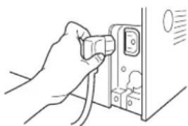
natural_image
Line drawing of a hand inserting a cable into a door panel (no text or symbols)
- Check whether the power cord is not stepped on or pinched by a table and so on.
Overheating may occur there, leading to a risk of fire.


WARNING: Power Plug and Cord
- Do not bundle or tie the power cord. Overheating may occur there, leading to a risk of fire.
- Check whether dust is collected around the power plug and wall outlet. Using the power plug and wall outlet without removing dust may result in fire.
- Do not insert the power plug into the wall outlet with a wet hand. The risk of electric shock exists.
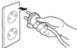
- When unplugging the power cord, grasp the plug, not the cable. The cable may be broken, leading to a risk of fire and electric shock.


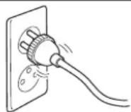
natural_image
Hand inserting a plug into an electrical socket (no text or symbols visible)


natural_image
Hand holding a plug inserted into an electrical socket (no text or symbols visible)
WARNING: Wiring
- Never use multi-plug adapters to plug multiple power cords in the same outlet. If used, the risk of fire exists.

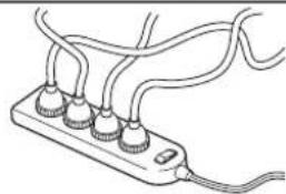
natural_image
Line drawing of a plug with multiple connectors and wires (no text or symbols)- When an extension cord is required, use a specified one. Current that can flow in the extension cord is limited, so using a too long extension cord may result in fire. Do not use an extension cable reel with the cable taken up. Fire may result.


natural_image
Line drawing of a wire spool with attached cable (no text or symbols)
WARNING: Ground Lead
- Check whether the copier is grounded properly. If current leakage occurs in an ungrounded copier, you may suffer electric shock while operating the copier. Connect the ground lead to one of the following points:

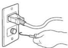
natural_image
Hand connecting a cable to an electrical outlet plug (no text or symbols visible)a. Ground terminal of wall outlet
b. Ground terminal for which Class D work has been done
WARNING: Ground Lead
- Pay attention to the point to which the ground lead is connected.
Connecting the ground lead to an improper point such as the points listed below results in a risk of explosion and electric shock:
a. Gas pipe (A risk of explosion or fire exists.)
b. Lightning rod (A risk of electric shock or fire exists.)
c. Telephone line ground (A risk of electric shock or fire exists in the case of lightning.)
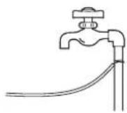
d. Water pipe or faucet (It may include a plastic portion.)

2. Installation Requirements
WARNING: Prohibited Installation Place
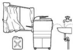
- Do not place the copier near flammable materials such as curtains or volatile materials that may catch fire.
A risk of fire exists.
- Do not place the copier in a place exposed to water such as rain water.
A risk of fire and electric shock exists.

natural_image
Line drawing of a kitchen sink with a refrigerator, toilet, and water dispenser (no text or symbols)
WARNING: Nonoperational Handling
- When the copier is not used over an extended period of time (holidays, etc.), switch it off and unplug the power cord.
Dust collected around the power plug and outlet may cause fire.


natural_image
Hand inserting a plug into an electrical socket (no text or symbols visible)CAUTION: Temperature and Humidity
- Do not place the copier in a place exposed to direct sunlight or near a heat source such as a heater.
A risk of degradation in copier performance or deformation exists.
Do not place the copier in a place exposed to cool wind.
Recommended temperature and humidity are as follows:
Temperature: 10°C to 30°C
Humidity: 10% to 80% (no dew condensation)
Avoid other environments as much as possible.


natural_image
Illustration of three household appliances: a refrigerator, a portable air conditioner, and a gas stove (no text or symbols present)CAUTION: Ventilation
- Do not place the copier in a place where there is much dust, cigarette smoke, or ammonia gas.
Place the copier in a well ventilated place to prevent machine problems and image faults.


natural_image
Illustration of a portable air conditioner with smoke and bubbles, no text or symbols presentCAUTION: Ventilation
• The copier generates ozone gas during operation, but it is not sufficient to be harmful to the human body.
If a bad smell of ozone is present in the following cases, ventilate the room.
a. When the copier is used in a poorly ventilated room
b. When taking a lot of copies
c. When using multiple copiers at the same time

text_image
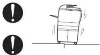
Illustration showing a document being discarded into a machine with warning symbols and stacks of waste nearbyCAUTION: Vibration
- When installing the copier, read the Installation Guide thoroughly. Be sure to install the copier in a level and sturdy place.
Constant vibration will cause problems.
text_image
Warning symbol and cartoon illustration of a suitcase with motion arrows, accompanied by two warning circles.- Be sure to lock the caster stoppers.
In the case of an earthquake and so on, the copier may slide, leading to a injury.
CAUTION: Inspection before Servicing

- Before conducting an inspection, read all relevant documentation (service manual, technical notices, etc.) and proceed with the inspection following the prescribed procedure in safety clothes, using only the prescribed tools. Do not make any adjustment not described in the documentation.
If the prescribed procedure or tool is not used, the copier may break and a risk of injury or fire exists.

natural_image
Illustration of four different wrenches: a pin, a screwdriver, an adjustable wrench, and a wrench (no text or symbols present)- Before conducting an inspection, be sure to disconnect the power plugs from the copier and options.
When the power plug is inserted in the wall outlet, some units are still powered even if the POWER switch is turned OFF. A risk of electric shock exists.

text_image
Diagram showing a hand using a power plug to install three outlets on a wall, with a battery icon and directional arrow.• The area around the fixing unit is hot.
You may get burnt.

natural_image
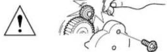
Simple line drawing of a heat exchanger with warning symbol (no text or labels)! DANGER: Work Performed with the Copier Powered
• Take every care when making adjustments or performing an operation check with the copier powered.
If you make adjustments or perform an operation check with the external cover detached, you may touch live or high-voltage parts or you may be caught in moving gears or the timing belt, leading to a risk of injury.

DANGER: Work Performed with the Copier Powered
• Take every care when servicing with the external cover detached. High-voltage exists around the drum unit. A risk of electric shock exists.


WARNING: Safety Checkpoints
- Check the exterior and frame for edges, burrs, and other damages. The user or CE may be injured.
- Do not allow any metal parts such as clips, staples, and screws to fall into the copier. They can short internal circuits and cause electric shock or fire.
- Check wiring for squeezing and any other damage. Current can leak, leading to a risk of electric shock or fire.
- When disconnecting connectors, grasp the connector, not the cable. (Specifically, connectors of the AC line and high-voltage parts) Current can leak, leading to a risk of electric shock or fire.
- Carefully remove all toner remnants and dust from electrical parts and electrode units such as a charging corona unit. Current can leak, leading to a risk of copier trouble or fire.
- Check high-voltage cables and sheaths for any damage. Current can leak, leading to a risk of electric shock or fire.
- Check electrode units such as a charging corona unit for deterioration and sign of leakage. Current can leak, leading to a risk of trouble or fire.
- Before disassembling or adjusting the write unit incorporating a laser, make sure that the power cord has been disconnected. The laser light can enter your eye, leading to a risk of loss of eyesight.
- Do not remove the cover of the write unit. Do not supply power with the write unit shifted from the specified mounting position. The laser light can enter your eye, leading to a risk of loss of eyesight.
- When replacing a lithium battery, replace it with a new lithium battery specified in the Parts Guide Manual. Dispose of the used lithium battery using the method specified by local authority. Improper replacement can cause explosion.


natural_image
Hand using a power tool to switch an electrical outlet (no text or symbols visible)


WARNING: Safety Checkpoints
- After replacing a part to which AC voltage is applied (e.g., optical lamp and fixing lamp), be sure to check the installation state. A risk of fire exists.
- Check the interlock switch and actuator for loosening and check whether the interlock functions properly. If the interlock does not function, you may receive an electric shock or be injured when you insert your hand in the copier (e.g., for clearing paper jam).
- Make sure the wiring cannot come into contact with sharp edges, burrs, or other pointed parts. Current can leak, leading to a risk of electric shock or fire.
- Make sure that all screws, components, wiring, connectors, etc. that were removed for safety check and maintenance have been reinstalled in the original location. (Pay special attention to forgotten connectors, pinched cables, forgotten screws, etc.) A risk of copier trouble, electric shock, and fire exists.


DANGER: HANDLING OF SERVICE MATERIALS
- Toner and developer are not harmful substances, but care must be taken not to breathe excessive amounts or let the substances come into contact with eyes, etc. It may be stimulative. If the substances get in the eye, rinse with plenty of water immediately. When symptoms are noticeable, consult a physician.
- Never throw the used cartridge and toner into fire. You may be burned due to dust explosion.


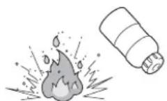

DANGER : HANDLING OF SERVICE MATERIALS
- Unplug the power cord from the wall outlet. Drum cleaner (isopropyl alcohol) and roller cleaner (acetone-based) are highly flammable and must be handled with care. A risk of fire exists.

natural_image
Hand holding a screwdriver next to a wall socket (no text or symbols visible)- Do not replace the cover or turn the copier ON before any solvent remnants on the cleaned parts have fully evaporated. A risk of fire exists.


- Use only a small amount of cleaner at a time and take care not to spill any liquid. If this happens, immediately wipe it off. A risk of fire exists.

- When using any solvent, ventilate the room well. Breathing large quantities of organic solvents can lead to discomfort.


natural_image
Illustration of a portable device emitting air from a stack of bottles, with no visible text or symbols.[3] MEASURES TO TAKE IN CASE OF AN ACCIDENT
![KONICA MINOLTA 7145 - [3] MEASURES TO TAKE IN CASE OF AN ACCIDENT - 1](/content/2026/05/1061009/images/7b1d32f50709866f6f1ee18c60ed16c89704934eabe9f17fe9cd9e77af357e71.jpg)
- If an accident has occurred, the distributor who has been notified first must immediately take emergency measures to provide relief to affected persons and to prevent further damage.
- If a report of a serious accident has been received from a customer, an on-site evaluation must be carried out quickly and KMBT must be notified.
- To determine the cause of the accident, conditions and materials must be recorded through direct on-site checks, in accordance with instructions issued by KMBT.
- For reports and measures concerning serious accidents, follow the regulations given in "Serious Accident Report/Follow-up Procedures".
[4] CONCLUSION
- Safety of users and customer engineers depends highly on accurate maintenance and administration. Therefore, safety can be maintained by the appropriate daily service work conducted by the customer engineer.
- When performing service, each copier on the site must be tested for safety. The customer engineer must verify the safety of parts and ensure appropriate management of the equipment.
SAFETY INFORMATION
IMPORTANT INFORMATION
The Center for Devices and Radiological Health (CDRH) of the U.S. Food and Drug Administration implemented regulations for laser products manufactured since August 1, 1976. Compliance is mandatory for products marketed in the United States.
This copier is certified as a "Class 1" laser product under the U.S.
Department of Health and Human Services (DHHS) Radiation Performance Standard according to the Radiation Control for Health and Safety Act of 1968. Since radiation emitted inside this copier is completely confined within protective housings and external covers, the laser beam cannot escape during any phase of normal user operation.
SAFETY CIRCUITS
This machine is provided with the following safety circuits to prevent machine faults from resulting in serious accidents.
[1] Overall protection circuit
[2] L2 and L3 (fixing heater lamp/1, /2) overheating prevention circuit
These safety circuits are described below to provide the service engineer with a renewed awareness of them in order to prevent servicing errors that may impair their functions.
[1] Overall protection circuit
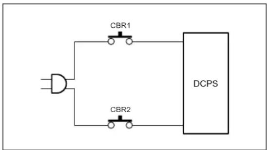
text_image
CBR1 CBR2 DCPS- Protection by CBR1 and CBR2 (circuit breaker/1, /2)
CBR1 and CBR2 interrupt the AC line instantaneously when an excessive current flows due to a short in the AC line.
CAUTION:
The CBR1 and CBR2 functions must not be deactivated under any circumstances.
[2] L2 and L3 (fixing heater lamp/1, /2) overheating prevention circuit

flowchart
graph TD
    A["TH1 TH2"] --> B["Control section"]
    B --> C["CB"]
    C --> D["AC driver section"]
    D --> E["DCPS"]
    E --> F["RL1"]
    F --> G["TS"]
    G --> H["L2"]
    G --> I["L3"]
    H --> J["FCB"]
    I --> J
    J --> K["RL1"]
    K --> L["DCPS"]
    style A fill:#f9f,stroke:#333
    style B fill:#ccf,stroke:#333
    style C fill:#cfc,stroke:#333
    style D fill:#fcc,stroke:#333
    style E fill:#cff,stroke:#333
    style F fill:#ffc,stroke:#333
    style G fill:#cfc,stroke:#333
    style H fill:#fcc,stroke:#333
    style I fill:#cfc,stroke:#333
    style J fill:#fcc,stroke:#333
    style K fill:#cfc,stroke:#333
    style L fill:#fcc,stroke:#333
- Protection by software
The output voltage from TH1, TH2 (fixing temperature sensor/1, /2) is read by the CPU. If this voltage is abnormal, L2 (fixing heater lamp/1), L3 (fixing heater lamp/2) and RL1 (main relay) are turned OFF.
CAUTION:
The RL1 function must not be deactivated under any circumstances.
2. Protection by the hardware circuit
The output voltages from TH1, TH2 (fixing temperature sensor/1, /2) are compared with the abnormality judgment reference value in the comparator circuit. If the output voltage from TH1 or TH2 exceeds the reference value, L2 (fixing heater lamp/1), L3 (fixing heater lamp/2) and RL1 (main relay) are turned OFF in hardware means.
CAUTION:
Periodically check the TH1, TH2 face contacting the roller, and replace TH2 if any abnormality is detected.
The RL1 function must not be deactivated under any circumstances.
3. Protection by TS (thermostat)
When the fixing heat roller exceeds the specified value, TSs (thermostats) are turned OFF, thus interrupting the power to L2 (fixing heater lamp/1), and L3 (fixing heater lamp/2) directly.

CAUTION:
Do not use any other electrical conductor in place of TS1 and TS2.
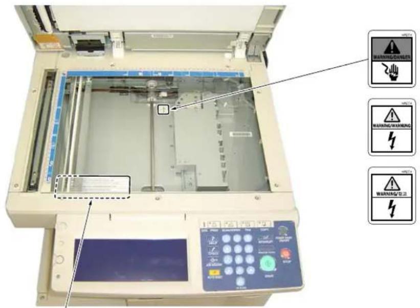
INDICATION OF WARNING ON THE MACHINE
Caution labels shown below are attached in some areas on/in the machine.
When accessing these areas for maintenance, repair, or adjustment, special care should be taken to avoid burns and electric shock.
② [1] Main body
1. Right side
<7145>
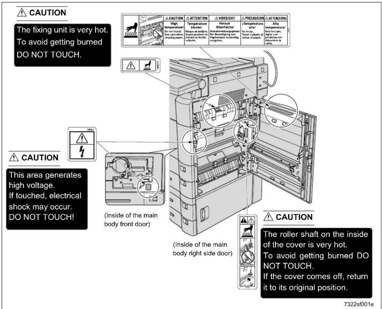
text_image
CAUTION The fixing unit is very hot. To avoid getting burned DO NOT TOUCH. CAUTION This area generates high voltage. If touched, electrical shock may occur. DO NOT TOUCH! CAUTION (Inside of the main body front door) (Inside of the main body right side door) CAUTION The roller shaft on the inside of the cover is very hot. To avoid getting burned DO NOT TOUCH. If the cover comes off, return it to its original position.CAUTION
You may be burned or injured if you touch any area that you are advised by any caution label to keep yourself away from.
Do not remove caution labels. If any caution label has come off or soiled and therefore the caution cannot be read, contact our Service Office.

<7235/7228/7222>
| CAUTION | High temperature! |
| PRECAUCION | Temperatura alta! |
| 注意 | 高温! |
| 위험 | 고열! |
| حرارة مالیاً |
| CAUTION | High temperature! |
| VORSICHT | Heisse Oberfläche! |
| ATTENTION | Température élevée! |
| PRECAUCION | ¡Temperatura alta! |
| ATTENZIONE | Alta temperatura! |
| CAUTION | High temperature! |
| ATTENTION | Température élevée! |
| PRECAUCION | ¡Temperatura alta! |
| 注意 | 高温! |
You may be burned or injured if you touch any area that you are advised by any caution label to keep yourself away from.
Do not remove caution labels. If any caution label has come off or soiled and therefore the caution cannot be read, contact our Service Office.

2. Front side

<7145>
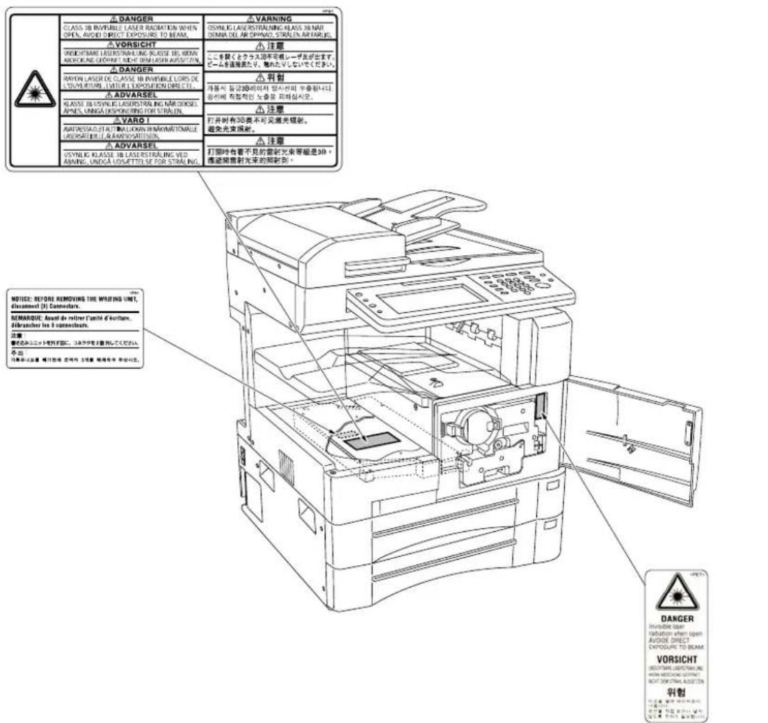
text_image
A DANGER CLASS BE INVISIBLE LASER RADIATION WHEN OPEN, AVOID DIRECT EXPOSURE TO BEAM. A VORSICHT DRINKING LASER STRAULING KLAUSE BE WITH BEARING OFFICE! RIGHT ON LAYER ASOCIATION. A DANGER RIVON LASER DE CLASSE BE INVISIBLE LORIS DE LAVOURING, WATER EXPOSITION DIRECT. A ADVARSEL KLASSE BE INVISIBLE LASER STRAULING MAR CHIKEL APES, UNIGA EXPOSING FOR STRALER. A YARD! ADPRESSED BY BALLOON WITH MARITOMILE UPRATED BY ANGOWEER. A ADVARSEL USYNEK KLASSE BE LASER STRAULING VED ABING, UNIGA USUSETTI OF FOR STRALER. VARIABLES WARNING 注意 注意 注意 注意 注意 注意 注意 注意 注意 注意 注意 注意 注意 注意 注意 注意 注意 注意 注意 注意 注意 注意 注意 注意 注意 注意 注意 注意 注意 注意 注意 注意 注意 注意 注意 注意 注意 注意 注意 注意 注意 注意 注意 注意 注意 注意 注意 注意 注意 注意 DANGER Institute the power Induction when open AVIDE DIRECT Exposure to BEAM. VORSICHT Not using a device or device for use in the system. NOT USING ASSETS. 引物 注释: 1. 2. 3. 4. 5. 6. 7. 8. 9. 10. 11. 12. 13. 14. 15. 16. 17. 18. 19. 20. 21. 22. 23. 24. 25. 26. 27. 28. 29. 30. 31. 32. 33. 34. 35. 36. 37. 38. 39. 40. 41. 42. 43. 44. 45. 46. 47. 48. 49. 50. 51. 52. 53. 54. 55. 56. 57. 58. 59. 60. 61. 62. 63. 64. 65. 66. 67. 68. 69. 70. 71. 72. 73. 74. 75. 76. 77. 78. 79. 80. 81. 82. 83. 84. 85. 86. 87. 88. 89. 90. 91. 92. 93. 94. 95. 96. 97. 98. 99. 100.7322sf003e

CAUTION
You may be burned or injured if you touch any area that you are advised by any caution label to keep yourself away from.
Do not remove caution labels. If any caution label has come off or soiled and therefore the caution cannot be read, contact our Service Office.

<7235/7228/7222>

You may be burned or injured if you touch any area that you are advised by any caution label to keep yourself away from.
Do not remove caution labels. If any caution label has come off or soiled and therefore the caution cannot be read, contact our Service Office.


3. Rear/Left side (7235/7228/7222 only)
text_image
警告 WARNING ADVERTÉNCIA 警告 경고 パネルを外す時は、電圧プラグを抜いてください。 Unplug the machine before removing panels. Desconecle a unidade da tomada antes de remover os painéis. 在取下后面板之前,请拔出电源插头。 판빌을 제거하기전에 기기의 전원 플러그를 돌아구십시오. WARNING DANGER ADVERTÉNCIA 警告 Unplug the machine before removing panels. Débrancher l'appareil avant de retirer les panneaux arrières. Desenchute la máquina antes de quitar los paneles. 在取下背蓋板之前,请拔出電源插頭。 WARNING ADVERTÉNCIA 警告 Unplug the machine before removing panels. Desenchute la máquina antes de quitar los paneles. 在取下后面板之前,请拔出电源插头。 판빌을 제거하기전에 기기의 전원 플러그를 돌아구십시오. ESCEP ESCEP ESCEP ESCEP ESCEP ESCEP ESCEP ESCEP ESCEP ESCEP ESCEP ESCEP ESCEP ESCEP ESCEP ESCEP ESCEP ESCEP ESCEP ESCEP ESCEP ESCEP ESCEP ESCEP ESCEP ESCEP
CAUTION
You may be burned or injured if you touch any area that you are advised by any caution label to keep yourself away from.
Do not remove caution labels. If any caution label has come off or soiled and therefore the caution cannot be read, contact our Service Office.
4. Scanner section
② <7145>
natural_image
Technical line drawing of a mechanical device with internal compartments and control panel (no text or symbols)7322sf006
CAUTION
You may be burned or injured if you touch any area that you are advised by any caution label to keep yourself away from.
Do not remove caution labels. If any caution label has come off or soiled and therefore the caution cannot be read, contact our Service Office.

<7235/7228/7222>
text_image
WARNING/DANANA WARNING/WARNING WARNING/2.21| 警告 | 原稿ガラスを取り外す時は、電源プラグを抜いてください。 |
| WARNING | Unplug the machine before removing platen glass. |
| ADVERTÊNCIA | Desconecte a unidade da tomada antes de remover o vidro de exposição. |
| 警告 | 在取下稿台玻璃之前,请拔出电源插头。 |
| 경고 | 원고유리판을 제거하기전에 기기의 전원코드를 훼아주십시오. |
| WARNING | Unplug the machine before removing piaten glass. | |
| DANGER | Débrancher le copieur avant de retirer la vitre d'exposition. | |
| ADVERTENCIA | Desenchufe la máquina antes de quitar el vidrio. | |
| 警告 | 在取下原稿台玻璃之前,請拔出電源插頭。 |
You may be burned or injured if you touch any area that you are advised by any caution label to keep yourself away from.
Do not remove caution labels. If any caution label has come off or soiled and therefore the caution cannot be read, contact our Service Office.
② [2] FS-113
![KONICA MINOLTA 7145 - ② [2] FS-113 - 1](/content/2026/05/1061009/images/65f8f8e0d16211a11e457be2c28a2805864e56c045ce17e135000ea65189b02a.jpg)
text_image
CAUTION This area is very hot. To avoid getting burned DO NOT TOUCH. (Inside of the Finisher) CAUTION Caution Attention Attention Voracit Precaution Precaution Cuidado FS-113 Finisher To avoid injury, DO NOT put your hand on the top of the printed sheets. Be sure to hold both sides of the printed sheets when removing them, and DO NOT leave your hand on the printed sheets while the primary (main) tray goes up.② [3] FS-114
![KONICA MINOLTA 7145 - ② [3] FS-114 - 1](/content/2026/05/1061009/images/6117a3d923031ee93d1a20ba121d6eb9d4aae6e16ee2e121508f25baea7328a9.jpg)
text_image
FS-114 Finisher 注意 CAUTION VORSICHT ATTENTION PRECAUCIÓN 7322sf010CAUTION
You may be burned or injured if you touch any area that you are advised by any caution label to keep yourself away from.
Do not remove caution labels. If any caution label has come off or soiled and therefore the caution cannot be read, contact our Service Office.

List of major differences between the 7145, 7235, 7228 and 7222
| Classification 7145 7235 7228 7222 Reason | |||||||
| Specifications | Warmup time | Less than 30 sec. | Less than 19 sec. | Change of specifications | |||
| First copy out time (8.5x11) | Less than 3.8 sec. | Less than 4.3 sec. | Less than 4.9 sec. | ||||
| Continuous copy speed (8.5x11) | 45 sheets/min. 35 sheets/min. 28 sheets/min. | 22 sheets/min. | |||||
| Maximum E-RDH memory | 320MB | ||||||
| DF Standard Optional | |||||||
| ADU Standard | |||||||
| Paper exit tray | Optional | Standard | |||||
| Machine dimensions (with DF and DB) | 23.2in (W) x 23.4in (D) x 42.6in (H) | 23.4in (W) x 25.8in (D) x 44.6in (H) | |||||
| Maintenance | Once every 120,000 copies | Once every 100,000 copies | |||||
| Materials | Developer | Exclusively for 7145 | Exclusively for 7235/7228/7222 | ||||
| Toner | Exclusively for 7145 | Exclusively for 7235 (Common to 7135) | Exclusively for 7228/7222 (Common to 7022/7120/7135) | ||||
| Drum | Exclusively for 7145 | Exclusively for 7235/7228/7222 | |||||
| Drive section | Flywheel f 103mm f 132mm | ||||||
| Developing sleeve drive | Developing motor | Main motor | |||||
| Vibration insulator Not provided Provided Not provided | |||||||
| Scanner section | Scanner drive board Provided | Not provided | |||||
| Write section | Laser | 2 beams | 1 beam | ||||
| Number of rotations of polygon motor | 27,165rpm 38,976rpm | 33,070rpm | Change of CPM | ||||
| Polygon cooling | Not provided Provided Not provided | Change of specifications | |||||
2
| Classification 7145 7235 7228 7222 Reason | ||||||
| Fixing section | Fixing unit | Exclusively for 7145 | Exclusively for 7235/7228/7222 | Change of specifications | ||
| ADU/Paper exit section | Decurler roller Provided | Not provided | ||||
| ADU drive board Not provided Provided | ||||||
| Electrical parts | Developing motor Provided Not provided | |||||
| ADU motor Provided | ||||||
| Fixing cooling fan Provided Not provided | ||||||
| Internal cooling fan/2 | Provided | Not provided | ||||
| Polygon cooling fan Not provided Provided Not provided | ||||||
| ADU gate solenoid Provided | ||||||
| ADU sensor Provided | ||||||
| Timing sensor/U | Provided | Not provided | ||||
| Timing sensor/L | Provided | Not provided | ||||
| Control | Overall control | Exclusively for 7145 | Exclusively for 7235 | Exclusively for 7228 | Exclusively for 7222 | |
| Image control | ||||||

List of options corresponding to the 7145/7235/7228/7222
| Optional 7145 7235 7228 7222 | |||||
| RADF DF-318 Standard Not corresponding | |||||
| Finisher FS-112 | Corresponding Not corresponding | ||||
| FT-107 | |||||
| FS-113 | Corresponding | ||||
| RU-101 | |||||
| FS-114 | |||||
| BK-114 | |||||
| PK-114 | |||||
| SK-114 | |||||
| Paper exit tray ET-101 Corresponding Corresponding*1 | |||||
| Inner tray IT-101 | Corresponding | ||||
| Desk DK-110 | Not corresponding | Corresponding | |||
| DB DB-211 | CorrespondingDB-411 | ||||
| LCT LT-203 | |||||
| ADU AD-307 | Standard | ||||
| Post script | PS-344 | Corresponding Not corresponding | |||
| PS-346 | Not corresponding | Corresponding | |||
| Printer controller | IP-432 | Corresponding Not corresponding | |||
| IP-424 | Not corresponding | Corresponding | |||
| FAX controll board | FK-102 Type-A | Corresponding Not corresponding | |||
| FK-103 | Not corresponding | Corresponding | |||
| 2 lines expansion kit | FL-102 | Corresponding Not corresponding | |||
| FL-103 | Not corresponding | Corresponding | |||
| Hard disk | HD-103 Type-A | Corresponding | |||
| Total counter | Standard | Corresponding | |||
| Key counter | Corresponding | ||||
*1 A paper exit tray is provided as standard equipment that is different from ET-101. When ET-101 is provided, it is integrated into the main body as seen from the point of design.
Blank Page
I O U T L I N E
1. OUTLINE OF SYSTEM
2

flowchart
graph TD
    A["16"] --> B["12"]
    C["13"] --> B
    B --> D["14"][19][15]
    D --> E["10"]
    E --> F["18"][1]
    F --> G["3"]
    G --> H["4"]
    H --> I["17"]
    I --> J["2"]
    J --> K["7322ma1001"]
    style A fill:#f9f,stroke:#333
    style C fill:#f9f,stroke:#333
    style B fill:#ccf,stroke:#333
    style D fill:#ccf,stroke:#333
    style E fill:#ccf,stroke:#333
    style F fill:#ccf,stroke:#333
    style G fill:#ccf,stroke:#333
    style H fill:#ccf,stroke:#333
    style I fill:#ccf,stroke:#333
    style J fill:#ccf,stroke:#333
    style K fill:#ccf,stroke:#333

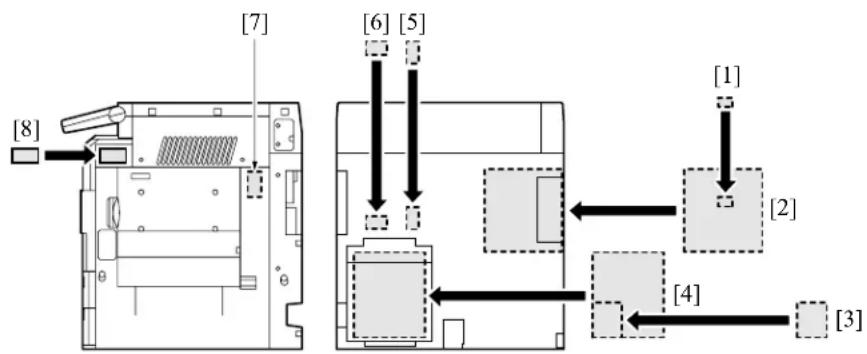
[1]Main body [10]
[3] LCT DB (DB-411)
[4] 2-Tray DB (DB-211)
[5] Conveyance unit (RU-101)
[6] Finisher (FS-113)
[7] Inner tray (IT-101)
[8] Finisher tray (FT-107: FS-112)
[9] Finisher (FS-112: 7145 only)
RADF (DF-318: 7145 provided as a standard equipment)
(DF-320: 7235/7228/7222)[2]LCT (LT-203)
[11] Paper exit tray (ET-101)*1
[12] Finisher (FS-114)
[13] Additional tray (BK-114)
[14] Punch kit (PK-114)
[15] Crease unit (included in SK-114)
[16] Saddle unit (SK-114)
[17] Desk (DK-110: 7235/7228/7222 only)
[18]ADU (provided as a standard equipment)
[19]Platen cover (CV-109: 7235/7228/7222 only)
*1 As a standard equipment, the 7235/7228/7222 are provided with a paper exit tray that is different from the one with which the ET-101 is equipped.
2
flowchart
graph TD
    A["Component 1"] --> B["Component 2"]
    B --> C["Component 3"]
    C --> D["Component 4"]
    D --> E["Component 5"]
    E --> F["Component 6"]
    F --> G["Component 7"]
    style A fill:#f9f,stroke:#333
    style B fill:#ccf,stroke:#333
    style C fill:#cfc,stroke:#333
    style D fill:#fcc,stroke:#333
    style E fill:#cff,stroke:#333
    style F fill:#ffc,stroke:#333
    style G fill:#fcf,stroke:#333
7145ma1020
[1]Postscript (PS-344: 7145)
(PS-346: 7235/7228/7222)
[2] Printer controller (IP-432: 7145)
(IP-424: 7235/7228/7222)
[3] 2 line expansion kit (shipments only to the
United States and
Oceania)
(FL-102:FK-102 Type-A)
(FL-103:FK-103)
[4]Fax control board(FK-102 Type-A: 7145)
(FK-103: 7235/7228/7222)
[5] E-RDH expansion memory (MU-404: 64MB/MU-405: 128MB)
[6] Hard disk (HD-103 Type-A)
[7] Total counter
(7145 provided as standard equipment)
(In the case of the 7235/7228/7222, shipments only to the United States are provided with the total counter.)
[8] Key counter
[9] Expansion memory for the printer controller
(Not displayed here. For details, see the
Service Manual of the controller.)

2. PRODUCT SPECIFICATIONS
A. Type

Type: Semi-console type (7145)
Desk-top type (7235/7228/7222)
Copying method: Indirect electrostatic method
Original table: Fixed
Original alignment: Left rear standard
Photosensitive material: OPC
Sensitizing method: Laser writing
Paper feed trays: Two trays (500 sheets x 2, 80g/m ^2 or 20lbs)
Multisheet bypass tray (50 sheets, 80g/m²)
DB-211 (500 sheets x 2, 80g/m² or 20lbs) *1
DB-411 (1500 sheets, 80g/m² or 20lbs) *1
LT-203 (2000 sheets, 80g/m² or 20lbs) *1
*1 Optional
B. Functions
Original: Sheet, book, solid object (Thickness: up to 1.2in. Weight: up to 15lbs)
Maximum original size: A3, or 11 x 17
Copy size (for metric area):
Tray 1: B4, A4, A4R, B5, B5R, A5R, 8.5 x 14, 8.5 x 11, 8.5 x 11R, 5.5 x 8.5R, F4
Tray 2: A3, B4, A4, A4R, B5, B5R, A5R, 11 x 17, 8.5 x 11, 8.5 x 11R, F4
Bypass tray: A3, B4, A4, A4R, B5, B5R, A5R, B6R, 8.5 x 11R (7145 only), 8.5 x 11 (except the 7145), F4 (except the 7145)
ADU: A3, B4, A4, A4R, B5, B5R, A5R, 11 x 17, 8.5 x 11, 8.5 x 11R, 8.5 x 14, 5.5 x 8.5R, F4
Copy size (for inch area):
Tray 1: 8.5 x 14, 8.5 x 11, 8.5 x 11R, 5.5 x 8.5R, F4, B4R (7145 only), A4, A4R, B5, A5R
Tray 2: 11 x 17, 8.5 x 14, 8.5 x 11, 8.5 x 11R, 5.5 x 8.5R, F4, A3, A4, A4R, A5R
Bypass tray: 11 x 17, 8.5 x 14, 8.5 x 11, 8.5 x 11R, 5.5 x 8.5R, A4
ADU: 11 x 17, 8.5 x 14, 8.5 x 11, 8.5 x 11R, 5.5 x 8.5R, A3, B4 (7145 only), A4, A4R, B5, A5R, F4
Magnification:
Fixed magnification (for metric area):
× 1.00, × 1.41, × 1.22, × 1.15, × 0.86, × 0.82, × 0.71
Fixed magnification (for inch area):
× 1.00, × 2.00, × 1.55, × 1.29, × 0.77, × 0.65, × 0.50
Special ratio: Three kinds
Zoom magnification: x 0.25 to x 4.00 (at 1% step)
Vertical magnification: x 0.25 to x 4.00 (at 1% step)
Horizontal magnification: x 0.25 to x 4.00 (at 1% step)
| △ Warm-up time: Less than 30 sec. (7145)(at temperature of 68°F, Less than 19 sec. (7235/7228/7222)at rated voltage) | ||
| △ First copy out time: Less than 3.8 sec. (7145) | ||
| Less than 4.3 sec. (7235) | ||
| Less than 4.9 sec. (7228/7222) | ||
| * platen mode, manual density, life size, tray 1, paper exit with face down,A4 or 8.5 x 11 | ||
| △ Continuous copy speed: 45 copies/min. (7145)(A4 or 8.5 x 11, 35 copies/min. (7235)in memory copy) 28 copies/min. (7228) | ||
| 22 copies/min. (7222) | ||
| Continuous copy count: Up to 999 | ||
| No. of sheets loadableon the paper exit tray: Up to 100 (8.5x11) | ||
| Copy density selection: AE, manual (9 steps), arbitrary density (2 modes) | ||
| Resolution:Scan: 600 dpi x 600 dpi | ||
| △ Write: 600 dpi x 600 dpi | ||
| ERDH memory *1: Standard 64MB, Maximum 320MB | ||
| △ Interface section: Serial port (USB TypeB), Serial port (RS-232C), RJ45 Ethernet connector,Parallel port (IEEE1284 (Compatible, Nible, ECP)) | ||
| Network section: | Ethernet frame type: | IEEE 802.3/802.3/Ethernet II/IEEE 802.3 SNAP |
| Connecting type: | 10 Base-T/100 Base-TX | |
| △ Corresponding protocol: | TCP/IP (BOOTP, ARP, ICMP, DHCP, SNMP, HTTP, SMTP, POP3, FTP, IPP)IPX/SPX, AppleTalk (EtherTalk), | |
| △ Corresponding OS: | Novell NetWare (3.x, 4.x, 5.x), Microsoft Windows 95/98/Me, Microsoft Windows NT4.0/2000/XP, Mac OS8.x and later Mac OS10.2.5 | |
| Multi-protocol: | Automatic discrimination | |
| Corresponding printing method: | Peer-to-Peer (TCP/IP), LPD/LPR (TCP/IP), PServer (IPX/SPX), RPrinter (IPX, SPX), AppleTalk (EtherTalk) | |
| General purpose utility: | Web browser (Internet Explorer, Netscape Navigator) | |
| Status indicator LED: | Green LED and orange LED, one for each | |
*1 Since the standard 64MB memory is packaged on the board, it is not possible to replace it with a new one.
Only one slot is provided for expansion. It can be installed with MU-404 (64MB), MU-405 (128MB), or 256MB (commercially available).
For 256MB (commercially available), be sure to use those of make and model No. specified separately.
Number of originals to be stored: More than 140 sheets under the following conditions:
Original: Konica standard chart
Density: Manual 5
Mode: Character/photograph
Memory capacity: 64MB (provided only as standard)
Job: Job in mode with page memory not used
C. Copy Paper

Plain paper: 60g/m
^2 or 17lbs to 105g/m ^2 or 28lbs, high-quality paper
Special paper *1 Label paper,
OHP film, blueprint-master paper, 50g/m
^2 or 13lbs to 59g/m ^2
or 16lbs high-quality paper (thin), 106g/m^2 or 28lbs to 130g/m^2 or 35lbs high-quality paper (thick1), 131g/m^2 or 35lbs to 160g/m^2 or 43lbs high-quality paper (thick2 *2)
*1 With bypass feed method, paper should be fed one sheet at a time. Double sided copy not allowed.
*2 Only bypass feed.
D. Machine Data
Power source: 230VAC -14% to 10.6% 50Hz/60Hz
120VAC -14% to 6% 60Hz
Power consumption: Maximum 1500W or less (fully optional)
Weight: Approximately 183lbs (with DF provided)

Dimensions: 7145: 23.2in (W) x 23.4in (D) x 42.6in (H) (with DF + DB)
7235/7228/7222: 23.4in (W) x 25.8in (D) x 44.6in (H) (with DF + DB)

E. Maintenance
Maintenance:
Once every 120,000 copies (7145)
Once every 100,000 copies (7235/7228/7222)

F. Consumables
Developer:
Exclusively for 7145
Exclusively for 7235/7228/7222
Toner:
Exclusively for 7145
Exclusively for 7235 (Common to 7135)
Exclusively for 7228/7222 (Common to 7022/7120/7130)
Drum:
Exclusively for 7145 ( 60)
Exclusively for 7235/7228/7222 ( 60)
G. Operating Environment
Temperature: 10°C to 30°C (50°F to 86°F)
Humidity: 10% RH to 80% RH
Note:
- The information herein may be subject to change for improvement without notice.

3. CENTER CROSS SECTION

text_image
[18][19][20] [17] [16] [15] [14] [13] [12] [11] [10] [1] [2] [3] [4] [5] [6] [7] [8] [9] 7322ma1002[1]Fixing unit [10]DB
[2]Drum unit [11]Developing unit
[3] Separation corona unit
[4] Transfer corona unit
[5] ADU unit
[6] Bypass tray

[7]Paper feed path for making a double-sided copy (DB unprovided)
[8]Paper feed path for making a double-sided copy (DB provided)
[9] DB paper feed path
[12] Tray 2
[13] Tray 1
[14] Charging corona unit
[15] Cleaning/toner recycling unit
[16] Toner bottle
[17] Scanner unit
[18] V-mirror unit
[19] Exposure unit
[20] CCD unit
4. DRIVE SYSTEM DIAGRAM
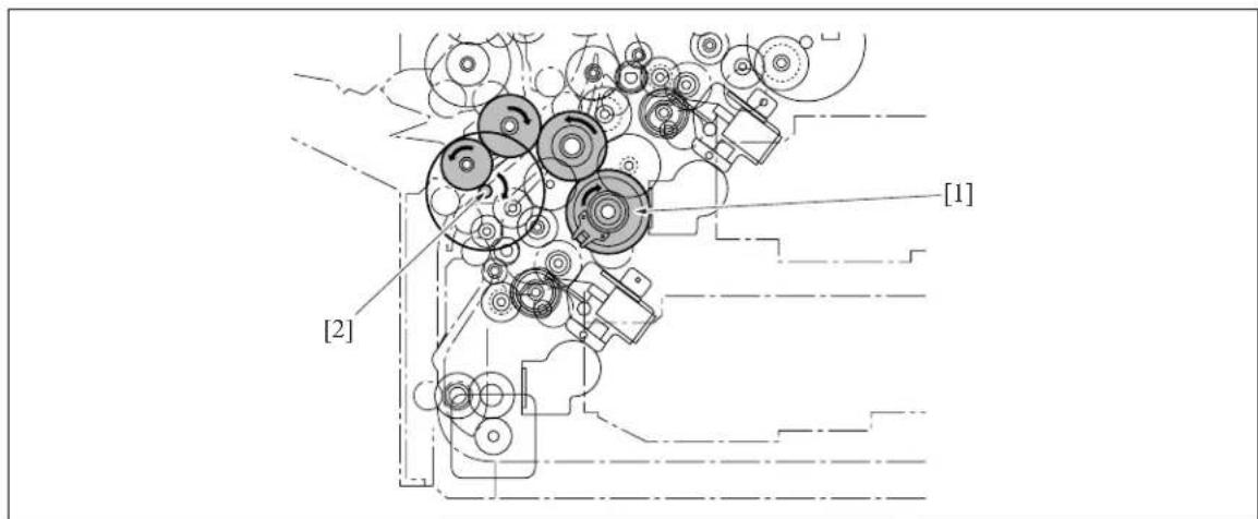
4.1 Drum Drive
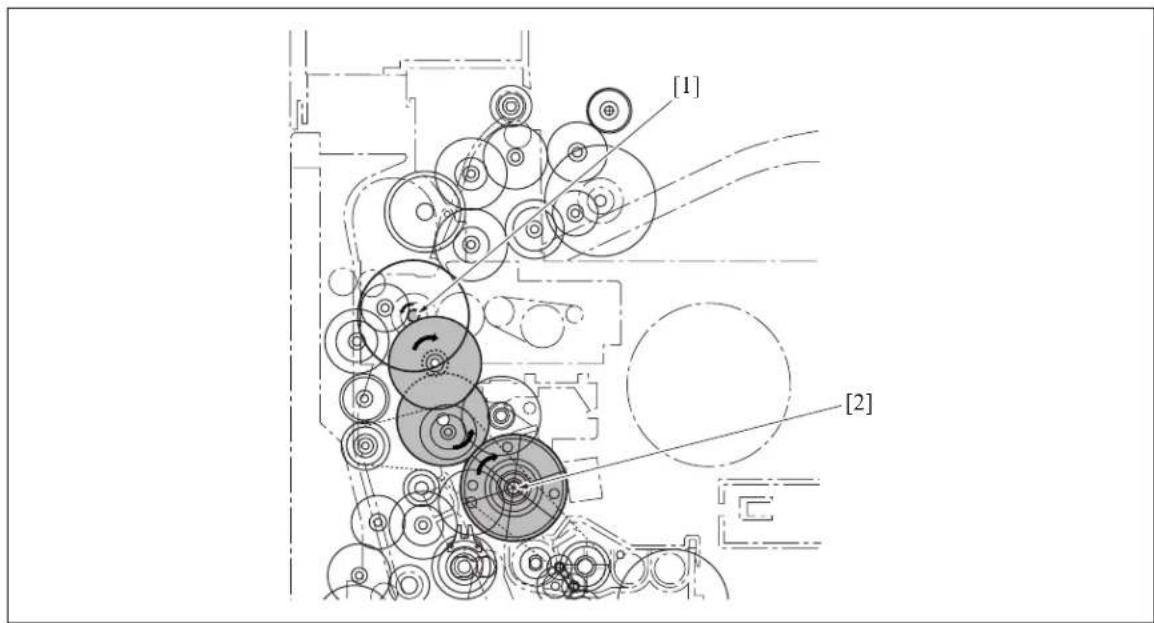
text_image
[1] [2][1]M1 (Main motor) [2]Drum drive shaft
4.2 Cleaning/Developer Agitation Drive

text_image
[1] [2] [3][1]M1 (Main motor) [3]Developer agitation drive
[2]Cleaning/toner recycling unit drive
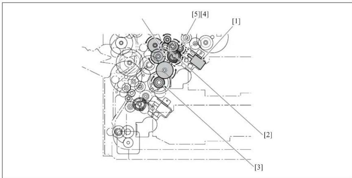
4.3 Fixing/Paper Exit Section/IT-101/RU-101 Drive

text_image
[4] [3] [5] [1] [2][1]IT-101 [4]Paper exit drive
[2] M11 (Fixing motor)
[3]Fixing unit drive
[5] Drive coupling for IT-101 and RU-101
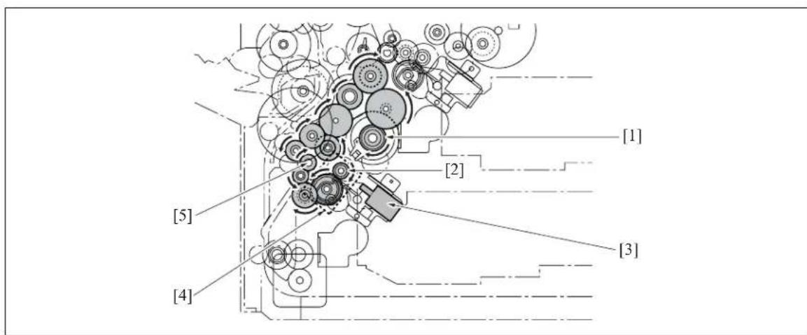
4.4 Developing Drive
In the case of the 7145
text_image
[1] [2] [3] [4][1] Developing sleeve
[2] Developing unit
[3] M3 (Developing motor)
[4] Drum drive shaft

In the case of the 7235/7228/7222

text_image
[1] [2] [3] [4] 7322ma1003[1]M1 (Main motor) [3]Developing unit
[2]Developing sleeve [4]Drum drive shaft
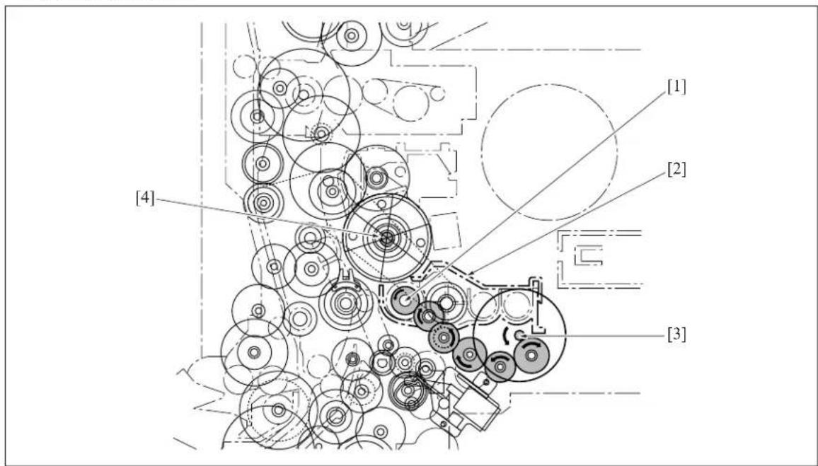
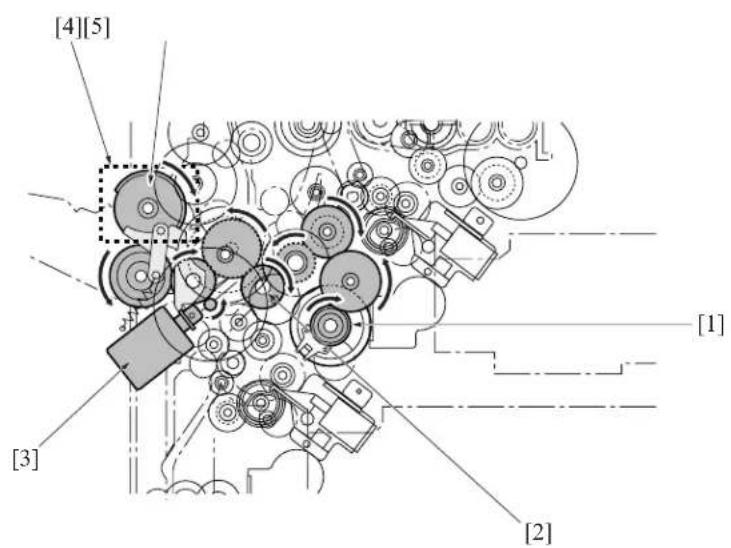
4.5 Paper Feed Drive
4.5.1 Drive from paper feed motor to loop clutch
text_image
[1] [2][1]MC2 (Loop clutch) [2]M9 (Paper feed motor)

4.5.2 Tray 1 drive
text_image
[5][4] [1] [2] [3][I] SD1 (1st paper feed solenoid/U)
[2] Conveyance roller
[3] MC2 (Loop clutch)
[4]Driven when SD1
(1st paper feed solenoid/U) is on.
[5] Feed roller
4.5.3 Tray 2 drive
text_image
[1] [2] [3] [4] [5][1] MC2 (Loop clutch)
[2] Feed roller
[3] SD2 (1st paper feed solenoid/L)
[4]Driven when SD2
(1st paper feed solenoid/L) is on.
[5] Conveyance roller
4.5.4 Bypass feed drive
text_image
[4][5] [3] [2] [1][1]MC2 (Loop clutch) [3]SD3 (Bypass solenoid)
[2] Conveyance roller
[4] Driven when SD3 (Bypass solenoid) is on.
[5]Paper feed roller
4.5.5 Registration clutch drive
text_image
[2] [1][1] M9 (Paper feed motor)
[2] MC1 (Registration clutch)
4.6 ADU Drive

text_image
[8] [7] [6] [5] [4] [3] [2] [1] [9][I]M1 (Main motor) [5]ADU roller
[2] Timing belt
[3] M9 (Paper feed motor)
[4] M6 (ADU motor)
[6] ADU conveyance roller/2
[7] Decurler roller
[8] ADU conveyance roller/1
[9]M11 (Fixing motor)
4.7 Scanner Drive

text_image
[3] [4] [5] [1] [2][1] Optical wire/R
[4] Exposure unit
[2] Optical wire/F
[5] M2 (Scanner motor)
[3]V-mirror unit
4.8 Toner Supply Drive

text_image
[1] [2] [3] [4] [5][1] Toner agitation plate
[2] Toner conveyance screw
[3]SD9 (Toner solenoid)
[4] M4 (Toner supply motor 1)
[5] M10 (Toner supply motor 2)
Blank page
II UNIT EXPLANATION
1. SCANNER SECTION
1.1 Composition
2

text_image
[7] [8] [9] [10] [11] [12] 7235/7228/7222 CB 7145 SCDB CB SCB [6] [5] [4] [3] [2] [1] 7322ma2001e| Symbol | Name Function or method | |
| [1]INV1 (Exposure lamp inverter) L1 (Exposure lamp) turn on | ||
| [2] | PS17 (APS sensor) | Detection of original size in the direction of sub-scanning |
| [3] | ADB (A/D converter board) | Digital conversion of analog signal |
| [4]CCD unit Photoelectric conversion of read image (600dpi) | ||
| [5]Exposure unit Image reading | Light source slit exposureScan speedForward: 230mm/sec. (in 1:1 magnification)Backward: 383mm/sec. | |
| [6]Optical wire Transmission of driving force from M2 to the exposure unit and the V-mirror unit (front and rear) | ||
| [7]V-mirror unit Reflection of reading light (2nd and 3rd mirrors) | ||
| [8]PS14 (Scanner HP sensor) Exposure unit HP detection | ||
| [9]L1 (Exposure lamp) Light source for reading image,Xenon lamp | ||
| [10] | L1INVB (Power supply board for exposure lamp) | Relay board for INV1 (Exposure lamp inverter) and L1 (Exposure lamp) |
| [11] | M2 (Scanner motor) | Driving of the optical wire used to move the exposure unit and the V-mirror unitThree-phase step motor |
| [12] | PS15 (APS timing sensor) | RADF open/close detection |

1.2 Operation
1.2.1 Initial operation when power is turned on and shading correction reading
When the SW2 (Sub power switch) comes on, the exposure unit starts a home position search. At this time, the exposure unit uses the white reference plate attached on the back side of the original pressing board for shading correction. However, two places on the white reference plate are read for correction. The search procedure differs depending on whether the PS14 (Scanner HP sensor) is on or off while the SW2 is on.

A. Home position search when the PS14 is turned on

flowchart
graph TD
    A["Step 1"] --> B["Step 2"]
    B --> C["Step 3"]
    C --> D["Step 4"]
    D --> E["End"]
    style A fill:#f9f,stroke:#333
    style B fill:#ccf,stroke:#333
    style C fill:#cfc,stroke:#333
    style D fill:#fcc,stroke:#333
    style E fill:#ffc,stroke:#333
[1] Exposure unit standby position
[2]PS14 [4]Shading correction position 2
[3] Shading correction position 1

B. Home position search when PS14 is turned off

flowchart
graph TD
    A["Step 1"] --> B["Step 2"]
    B --> C["Step 3"]
    C --> D["Step 4"]
    D --> E["End"]
    style A fill:#f9f,stroke:#333
    style B fill:#ccf,stroke:#333
    style C fill:#cfc,stroke:#333
    style D fill:#fcc,stroke:#333
    style E fill:#ffc,stroke:#333
[1] Exposure unit standby position
[2]PS14 [4]Shading correction position 2
[3] Shading correction position 1
1.2.2 Original reading mode
The following two modes are available for original reading; platen mode and DF mode. In platen mode, the exposure unit moves as necessary to scan the original for reading. In DF mode, the RADF side moves the original while the exposure unit stays fixed in a specified position (DF reading position).

A. Exposure unit movement in platen mode
In platen mode, the scan sequence depends on the copy density selection (either AE or manual).

(1) In manual density copy:

flowchart
graph TD
    A["1"] --> B["2"]
    B --> C["3"]
    C --> D["4"]
    D --> E["5"]
7322ma2017
[1] Exposure unit standby position
[2] PS14
[3] Shading correction position 1
[4] Shading correction position 2
[5]Position at which the approach run of the exposure unit is started
[6]Position at which the reading of an image is started
Note:
- When the tray 1 is selected manually, but not in APS, the shading operation is not executed.

(2) In AE copy:
text_image
[6][4][5] [1][7] [2]7322ma2018
[1] Exposure unit standby position
[2] AE scanning range
[3] PS14
[4] Shading correction position 1
[5]Shading correction position 2
[6]Position at which the approach run of the exposure unit is started
[7]Position at which the reading of an image is started

B. Exposure unit movement in DF mode
flowchart
graph LR
    A["Input Signal: [5"]] --> B["Step Function: [42"][3]]
    B --> C["Output Signal: [1"]]
7322ma2019
[1] Exposure unit standby position
[2]PS14 [5]DF reading position
[3]Shading correction position 1
[4] Shading correction position 2
1.2.3 Original read control
The light from the exposure lamp reflects back from the original, passes through a lens, and hits the CCD sensor. The CCD sensor generates an electric signal (analog signal) corresponding to the light intensity. Then, according to the instruction from the SCB (System control board), the ADB (A/D conversion board) converts this signal into a digital signal.
A. Original read timing
(1) Platen mode, when the manual density is being set

flowchart
graph TD
    A["M2 (Scanner motor)"] --> B["F"]
    A --> C["R"]
    D["PS14 (Scanner HP sensor)"] --> E["1"][3][4]
    D --> F["2"][5]
    style A fill:#f9f,stroke:#333
    style D fill:#ccf,stroke:#333
    style B fill:#dfd,stroke:#333
    style C fill:#dfd,stroke:#333
    style E fill:#dfd,stroke:#333
    style F fill:#dfd,stroke:#333
[1] START button (ON) [4]
[2] Exposure lamp (forward)
[3]Position to which the exposure unit starts
(2) Platen mode, when the AE density is being set
flowchart
graph TD
    A["M2 (Scanner motor)"] --> B["F"]
    A --> C["R"]
    D["PS14 (Scanner HP sensor)"] --> E["[1"]]
    D --> F["[3"]]
    D --> G["[4"]]
    D --> H["[7"]]
    D --> I["[3"]]
    D --> J["[6"]]
    style A fill:#f9f,stroke:#333
    style D fill:#ccf,stroke:#333
[1] START button (ON)
[2] AE scanning (forward)
[3] Position to which the exposure unit starts
[4] Position at which reading of the AE density started
[5] AE scanning (backward)
[6] Exposure lamp (forward)
[7] Position at which reading of the original starts
[8] Exposure scanning (backward)
B. Original read timing (DF mode) *1

other
| Motor | Time (ms) | |-------|-----------| | M2 (Scanner motor) | F | | R | 250 | | PS14 (Scanner HP sensor) | 460 | | M301 (Original feed motor) | R | | F | 230 | | PS302 (Original conveyance motor) | 230 | | PS308 (Original registration sensor) | 460 |[1] START button (ON)
[2]DF reading position [5]
[3]Position to which the original has been conveyed in the specified distance.
[4] Exposure conveyance
Position at which reading of the original starts.
[6] Starting point from the DF reading position to the home position (exposure unit).
*1 In the DF mode, the operation when the manual density setting and the AE density setting is the same.
1.2.4 APS control
The APS control is carried out at close detection of the RADF, and controlled by the CB (Main body control board), based on signals from the PS17 (APS sensor) and the CCD sensor. (For APS control by the RADF, see DF service manual.)
A. APS operation
The PS17 (APS sensor) detects the original size in the sub scanning direction, while the CCD sensor detects the original size in the main scanning direction.
B. Relationship between each of the sensors and the original size
| Original size CCD sensor | (Length of detection: mm) | PS17(ON/OFF) | |
| A3 297 ON | |||
| 11 x 17 279.4 ON | |||
| B4 257 ON | |||
| Original size | CCD sensor(Length of detection: mm) | PS17(ON/OFF) | |
| 8.5 x 14 *1 215.9 ON | |||
| 8.5 x 11R 215.9 Metric system: ON Inch system: OFF | |||
| A4R 210 Metric system: ON Inch system: OFF | |||
| A4 297 OFF | |||
| 8.5 x 11 279.4 OFF | |||
| B5R 257 OFF | |||
| A5R 210 OFF | |||
| B5 182 OFF | |||
| A5 148 OFF | |||
| 5.5 x 8.5 139.7 OFF | |||
| B6 128 OFF | |||
| Postcard | 102 OFF | ||
*1 8.5 x 14 cannot be distinguished from 8.5 x 11R, and is detected as 8.5 x 11R.
C. APS detection timing
(1) Platen mode (when the RADF is closed)
text_image
PS17 (APS sensor) PS15 (APS timing sensor) PS303 (DF open/close sensor)[1] 1st original size detection
[2] 2nd original size detection
(2) Platen mode (when the RADF is open)

text_image
PS17 (APS sensor) PS15 (APS timing sensor) PS303 (DF open/close sensor) [1] [2][1] Original size detection
[2] START button (ON)
1.2.5 AE control
During AE scan, the CCD sensor provided on the ADB (A/D conversion board) reads the density level of the original. The CPU on the SCB (System control board) process the data and, based on the results, selects the correction curve that will best reproduce the original.
A. AE sampling range
(1) While in platen copying
Main scanning direction
- Based on the original size recognized in the APS or out-of-original erasure mode, the range excepting 10mm in front and in rear.
Sub-scanning direction
- The range of 30mm from the leading edge of the original. However, the range excepting L/100mm in left and right when the length of the original is L mm.

text_image
[3] 10 mm [2] 10 mm L/100 mm 30 mm L mm [1][1] Original
[3] AE sampling range
[2] Leading edge of original
(2) While in DF copying
Main scanning direction
- Based on the original size recognized in the APS, the range excepting 20mm in front and in rear.
Sub-scanning direction - The range between 1.5mm and 2.9mm from the leading edge of the original.
text_image
[3] 20 mm [2] 20 mm 1.5 mm 2.9 mm 1.4 mm [1][1]Original [3]AE sampling range
[2] Leading edge of original
1.2.6 Image processing
A. AOC (Automatic offset control)
The analog offset voltage for the CCD sensor output is automatically adjusted by IC on the ADB (A/D conversion board) so that this level becomes the lower limit for the A/D converter.
B. AGC (Automatic gain control)
The analog amplification for the CCD sensor output is automatically adjusted so that the CCD sensor output level in the shading white correction becomes the upper limit for the A/D converter.
C. Shading correction
(1) Types of the shading correction
- White correction
- Black correction
(2) Execution timing
- At SW2 (Sub power switch) ON
- At the start of scan job
D. Other image processing
(1) Brightness/density conversion
(2) Text/dot pattern judgement
(3) Filtering
(4) Magnification change processing
(5) Error diffusion processing
(6) Data compression/elongation processing
2. WRITE UNIT
2.1 Composition
2
text_image
CB SCB [5] [6] [7] [8] [9] [10] [11] [1] 7235 only FM7 [4] [3] [2] 7322ma20022
| Symbol Name Function or method | |
| [1]Index lens Converging of laser beams reflected from the index mirror | |
| [2]INDEX (Index sensor board) | Control of the laser write position in the main scanning direction |
| [3]Polygon mirror Laser beam scanning | Hexahedron, 27,165rpm (7145) /38,976rpm (7235) /33,071rpm (7228/7222) |
| [4]M5 (Polygon motor) Polygon mirror driveDC brushless motor, PLL control | |
| [5]LDB (LD drive board) Laser emission drive1-chip/2-beam system, 15mW 780mm (7145)1-chip/1-beam system, 5mW 780mm (Except the 7145) | |
| [6]Collimator lens Making diffused laser beam parallel | |
| [7]Cylindrical lens 1 | Correction of the laser path against error in the angle of the polygon mirror |
| [8]Index mirror Reflection of laser beam upon the INDEX (Index senror board) | |
| [9]f0 lens | Unified laser scanning speed against the laser irradiation surface on the drum |
| [10]Cylindrical lens 2 | Correction of the laser path against error in the angle of the polygon mirror |
| [11]Dust-proof glass | Preventive measure for keeping the interior of the write unit clean |
| FM7*1 Polygon cooling fan | Cooling of the M5 (Polygon motor) |
2
2
2
*1 7235 only

2.2 Operation
2.2.1 Image writing
The image data from the CCD sensor is converted into digital form by the ADB (A/D conversion board), and its image processing is then carried out on the SCB (System control board). Based on the processed image data, the image is written onto the drum by the laser beam output from the LDB (LD drive board).
2.2.2 Write control
A. Dot diameter adjustment
The sensor on the toner control sensor board detects the patch image density on the drum, and the LDB (LD drive board) controls the quantity of laser beam so that its output value becomes the specified value.
(1) Timing for execution
a. While in copying
- Executed once for every 20 copies added up. However, when 20 copies are added up in the middle of the job, the execution is made at the time of completion of the job.
b. Anytime other than while in copying
- While in the L inspection
- When the drum counter is reset
- When the sub power is turned on. However, this is subject to the settings 6 and 7 of the DIPSW16 in the 25 mode.
B. APC (Automatic power control)
The LDB (LD drive board) monitors the laser output value for every one scan, and maintains the laser beam quantity at the fixed level by driving the laser so that it becomes the output value set for the dot diameter adjustment.
2 C. Write timing
The SCB (System control board) uses a laser detection signal from the INDEX (Index sensor board) to determine the starting point for laser writing for every one scan in the drum shaft direction.
3. DRUM UNIT
3.1 Composition

flowchart
graph TD
    CPU["CPU"] --> M1["M1"]
    CPU --> SD7["SD7"]
    CPU --> HV["HV"]
    CPU --> TCSB["TCSB"]
    CPU --> [10][9][8][7]
    CPU --> [6]
    CPU --> [5]
    CPU --> [4]
    CPU --> [2][3]
    CPU --> [1]
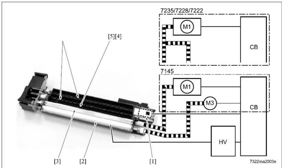
| Symbol | Name Function or method | |
| [1]TSL | (Transfer synchronization lamp) | Separation supportLED |
| [2]Transfer corona unit Transfer of toner | from the drum to paperDC positive corona discharge *1Wire discharge: Tungsten wire with oxide film (φ 0.06mm)With manual wire cleaning mechanism providedConstant current DC output range: 0 to 350 ∝A | |
| [3]Paper entrance guide plate Conveyance | guide for paper suppliedHigh voltage applied to prevent toner adhesion: -500VDC (constant voltage) | |
| [4]Drum Image formation base | OPC drum (φ 60mm) | |
| [5]Developing unit Formation of a toner image on the drum(See “4. Developing unit”.) | ||
| [6]Charging corona unit Application of electric charge on the drum surfaceDC corona discharge (Scotron)Wire discharge: Gold-plated skin-pass tungsten wire (φ 0.06mm)With manual wire cleaning mechanism providedConstant current DC output range: -320 to -1000 ∝AGrid bias: Charging control plateConstant current DC output range: -450 to -1090V | ||
2
| Symbol | Name | Function or method |
| [7]PCL | (Pre-charging exposure lamp) | Erasure of potential on the drum surfaceLED |
| [8]Cleaning/recycle section Cleaning and collection of toner on the drum(See “5. Toner supply/cleaning/recycle section”.) | ||
| [9]Separation claw Support for the separation of paper from the drumPressure/release method by SD7 (Separation claw solenoid) | ||
| [10]Separation corona unit Separation of transferred paper from the drumAC/DC corona discharge *1Wire discharge: Tungsten wire with oxide film ( 0.06mm)With manual wire cleaning mechanism providedConstant current AC output range: 1.5 to 5.0kVConstant current DC output range: 0 to -300 × A | ||
| SD7 Separation claw solenoid Separation claw pressure/release24VDC drive | ||
| M1 Main motor Driving of the drum, cleaning/recycling sectionDC brushless motor, PLL control | ||
| HV High voltage power High voltage power supply to the charging corona, transfercorona, separation corona, paper entrance guide plate anddeveloping biasMethod to increase voltage by inverter from 24VDC | ||
| TCSB | Toner control sensor board | Detection of the patch image density on the drumDetection of temperature around the drum |
*1 Control is made so that an output value becomes a little higher for a thick paper and a little lower for a thin paper as compared with a plain paper.
Note for the transfer/separation corona

Caution:
- A copy should not be made when the ADU door is open with the interlock forcibly turned on. Otherwise, the contact (spring) of the ADU door develops high voltage and you may get an electric shock.
2
text_image
[1] [2] [3] [4][1] ADU door
[2] Contact
[3] Transfer/separation corona unit
[4] HV (High voltage unit)
3.2 Operation
3.2.1 Image formation timing (when copying two sheets)
A. In the case of the 7145

flowchart
graph TD
    M1["Main motor"] --> M3["Developing motor"]
    M3 --> PS1["Registration sensor"]
    PS1 --> MC1["Registration clutch"]
    MC1 --> PCL["Pre-charging exposure lamp"]
    PCL --> HV1["Charging corona"]
    PCL --> HV2["Developing bias"]
    HV1 --> HV3["Transfer corona"]
    HV2 --> HV4["Separation corona"]
    HV3 --> HV5["Paper entrance guide plate"]
    HV4 --> TSL["Transfer synchronization lamp"]
    TSL --> DS7["Separation claw solenoid"]
    DS7 --> PS2["Fixing exit sensor"]

    subgraph Signal Path
        direction LR
        M1 --> M3
        M3 --> PS1
        PS1 --> MC1
        MC1 --> PCL
        HV1 --> HV2
        HV2 --> HV3
        HV3 --> TSL
        TSL --> DS7
        PS2 --> PS2

    end

    M1 --> M3
    M3 --> PS1
    PS1 --> MC1
    MC1 --> PCL
    PCL --> HV1
    HV1 --> HV2
    HV2 --> HV3
    HV3 --> TSL
    TSL --> DS7
    DS7 --> PS2

    style M1 fill:#000,stroke:#000,color:#fff
    style M3 fill:#000,stroke:#000,color:#fff
    style PS1 fill:#000,stroke:#000,color:#fff
    style MC1 fill:#000,stroke:#000,color:#fff
    style PCL fill:#000,stroke:#000,color:#fff
    style HV1 fill:#000,stroke:#000,color:#fff
    style HV2 fill:#000,stroke:#000,color:#fff
    style HV3 fill:#000,stroke:#000,color:#fff
    style TSL fill:#000,stroke:#000,color:#fff
    style DS7 fill:#000,stroke:#000,color:#fff
    style PS2 fill:#000,stroke:#000,color:#fff

    %% Legend: [2], [3][1]
    %% Note: Diagram includes 'Main motor', 'Developing motor', 'Registration sensor', etc.
    %% Values labeled on diagram edges.
[1] START button (ON)
[2]Varies depending on the type of paper.
[3] Driving of the separation claw to prevent the trailing edge of paper from getting stained.

B. In the case of the 7235/7228/7222

flowchart
graph TD
    A["M1 (Main motor)"] --> B["PS1 (Registration sensor)"]
    A --> C["MC1 (Registration clutch)"]
    A --> D["PCL (Pre-charging exposure lamp)"]
    A --> E["HV (Charging corona)"]
    A --> F["HV (Developing bias)"]
    A --> G["HV (Transfer corona)"]
    A --> H["HV (Separation corona)"]
    A --> I["HV (Paper entrance guide plate)"]
    A --> J["TSL (Transfer synchronization lamp)"]
    A --> K["DS7 (Separation claw solenoid)"]
    A --> L["PS2 (Fixing exit sensor)"]

    B --> M["Flow path with arrows"]
    C --> M
    D --> M
    E --> M
    F --> M
    G --> M
    H --> M
    I --> M
    J --> M
    K --> M
    L --> M

    subgraph Control Path
        M1 --> M1a["->"]
        M2 --> M2a["->"]
        M3 --> M3a["->"]
        M4 --> M4a["->"]
        M5 --> M5a["->"]
        M6 --> M6a["->"]
        M7 --> M7a["->"]
        M8 --> M8a["->"]
        M9 --> M9a["->"]
        M10 --> M10a["->"]
        M11 --> M11a["->"]
        M12 --> M12a["->"]
        M13 --> M13a["->"]
        M14 --> M14a["->"]
        M15 --> M15a["->"]
        M16 --> M16a["->"]
        M17 --> M17a["->"]
        M18 --> M18a["->"]
        M19 --> M19a["->"]
        M20 --> M20a["->"]
        M21 --> M21a["->"]
        M22 --> M22a["->"]
        M23 --> M23a["->"]
        M24 --> M24a["->"]
        M25 --> M25a["->"]
        M26 --> M26a["->"]
        M27 --> M27a["->"]
        M28 --> M28a["->"]
        M29 --> M29a["->"]
        M30 --> M30a["->"]
        M31 --> M31a["->"]
        M32 --> M32a["->"]
        M33 --> M33a["->"]
        M34 --> M34a["->"]
        M35 --> M35a["->"]
        M36 --> M36a["->"]
        M37 --> M37a["->"]
        M38 --> M38a["->"]
        M39 --> M39a["->"]
        M40 --> M40a["->"]
        M41 --> M41a["->"]
        M42 --> M42a["->"]
        M43 --> M43a["->"]
        M44 --> M44a["->"]
        M45 --> M45a["->"]
        M46 --> M46a["->"]
        M47 --> M47a["->"]
        M48 --> M48a["->"]
        M49 --> M49a["->"]
        M50 --> M50a["->"]
        M51 --> M51a["->"]
        M52 --> M52a["->"]
        M53 --> M53a["->"]
        M54 --> M54a["->"]
        M55 --> M55a["->"]
        M56 --> M56a["->"]
        M57 --> M57a["->"]
        M58 --> M58a["->"]
        M59 --> M59a["->"]
        M60 --> M60a["->"]
        N1 --> N1a["->"]
    end

    subgraph Control Path
        N2 --> N2a["->"]
        N3 --> N3a["->"]
        N4 --> N4a["->"]
        N5 --> N5a["->"]
        N6 --> N6a["->"]
        N7 --> N7a["->"]
        N8 --> N8a["->"]
        N9 --> N9a["->"]
        N10 --> N10a["->"]
        N11 --> N11a["->"]
        N12 --> N12a["->"]
        N13 --> N13a["->"]
        N14 --> N14a["->"]
        N15 --> N15a["->"]
        N16 --> N16a["->"]
        N17 --> N17a["->"]
        N18 --> N18a["->"]
        N19 --> N19a["->"]
        N20 --> N20a["->"]
        N21 --> N21a["->"]
        N22 --> N22a["->"]
        N23 --> N23a["->"]
        N24 --> N24a["->"]
        N25 --> N25a["->"]
        N26 --> N26a["->"]
        N27 --> N27a["->"]
        N28 --> N28a["->"]
        N29 --> N29a["->"]
        N30 --> N30a["->"]
        N31 --> N31a["->"]
        N32 --> N32a["->"]
        N33 --> N33a["->"]
        N34 --> N34a["->"]
        N35 --> N35a["->"]
        N36 --> N36a["->"]
        N37 --> N37a["->"]
        N38 --> N38a["->"]
        N39 --> N39a["->"]
        N40 --> N40a["->"]
    end

    style Control Path fill:#f9f,stroke:#333,stroke-width:2px
    style Control Path subgraph Control Path
    direction TB
    direction LR
    direction LR
    direction LR
    direction LR
    direction LR
    direction LR
    direction LR
    direction LR
    direction LR
    direction LR
    direction LR
    direction LR
    direction LR
    direction LR
    direction LR
    direction LR
    direction LR
    direction LR
    direction LR
    direction LR
    direction LR
    direction LR
    direction LR
    direction LR
    direction LR
    directionLR
    directionLR
    directionLR
    directionLR
    directionLR
    directionLR
    directionLR
    directionLR
    directionLR
    directionLR
    directionLR
    directionLR
    directionLR
    directionLR
    directionLR
    directionLR
    directionLR
    directionLR
    directionLR
    directionLR
    directionLR
    directionLR
    directionLR
    directionLR
    directionLR
    directionL
[1] START button (ON)
[2] Varies depending on the type of paper.
[3] Varies depending on the environment in which it is installed.

4. DEVELOPING UNIT
4.1 Composition
2
text_image
7235/7228/7222 M1 CB 7145 M1 M3 CB HV 7322ma2003e [5][4] [3] [2] [1]| Symbol | Name Function or method | |
| [1]TDS | (Toner density sensor) Detection | of toner density in the developing unitL detection method |
| [2]Developing sleeve Coveyance of developing materials by magnetic force to the drum surfaceTwo-component developing method (developing materials: Toner + Carrier)Developing bias voltage appliedConstant voltage DC output range: -350 to -830V | ||
| [3] | Developing regulation plate | Regulation of the spiking amount of developing materials on the developing sleeveRegulation plate method |
| [4]Agitator screw Agitation of developer and conveyance of developing materials to the agitator wheelAgitator wheel method | ||
| [5]Agitator wheel Agitation of developer and conveyance of developing materials to the developing sleeve4-vane wheel method | ||
| M1 Main motor Driving of the agitating turbine, the agitating screw and the developing sleeve (except the 7145)DC brushless motor, PLL control | ||
| M3*1 Developing motor Driving of the developing sleeve | ||
2
2
2
*1 7145 only
4.2 Operation
4.2.1 Developing control
For details of each operation timing of developing, see "3. Drum section".
4.2.2 Control of toner density in the developing unit
The TDS (Toner density sensor) uses the L detection method (detection of permeability in developing materials) to detect the toner density of developing materials. The value thus obtained is compared with the standard value of the toner density for the L detection adjustment that is recorded in the PCU contained in the CB (Main body control board) to see if toner should be supplied or not. (For details of toner supply, see "5. Toner supply/cleaning/recycling section".)
5. TONER SUPPLY/CLEANING/RECYCLE UNIT
5.1 Composition
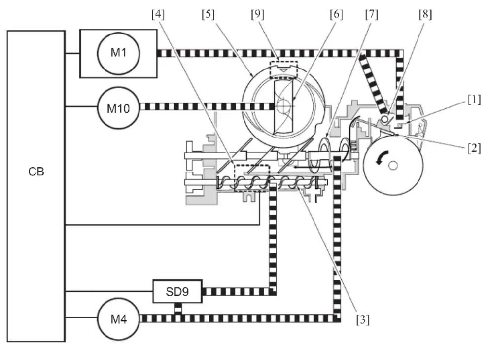
text_image
CB M1 M10 [4] [5] [9] [6] [7] [8] [1] [2] [3] M4 SD9| Symbol | Name Function or method | |
| [1] | Toner collection sheet | Collection of toner separated by the cleaning blade from the drum surfaceRotating collection method |
| [2] | Cleaning blade Drun cleaning | Drum contact/separation method |
| [3] | Toner conveyance screw | Agitation of toner and conveyance of toner to the developing unit Screw method |
| [4] | TLD (Toner level sensor) | Detection of the toner level in the toner supply unit (Detected when the residual quantity of toner gets to about 30g.)Piezo element method |
| [5] | Toner bottle Toner supply (bottle capacity: 676g)Toner bottle rotation method | |
| [6] | Toner supply paddle Conveyance of toner from the toner bottle to the toner supply unitFixed method (Since the toner bottle rotates, this serves as the toner introduction section.) | |
| [7] | Toner agitation plate | Agitation of toner supplied from the toner bottle and the cleaning/ recycle section, and conveyance of the toner to the toner convey-ance screwScrew method |
| [8] | Collected toner conveyance screw | Conveyance of toner from the cleaning section to the toner supply unitScrew method |
| [9]PS5 | (Toner bottle sensor) Detection | of the setting of the toner bottlePhotosensor |
| M1 | Main motor Driving of the toner collection sheet and the collected toner conveyance screwDC brushless motor, PLL control | |
| M4 | Toner supply motor 1 Driving of the toner conveyance screw and the toner agitator plateStepping motor | |
| M10 | Toner supply motor 2 Toner bottleStepping motor | |
| SD9 | Toner solenoid Transmission of driving force from the M4 (Toner supply motor) to the toner conveyance screw24VDC drive | |
5.2 Operation
5.2.1 Toner supply control when the toner level in the toner supply section gets reduced
A. Toner supply operation:
When toner in the toner supply unit is running short, the TLD (Toner level sensor) turns on. This causes the M10 (Toner supply motor 2) to turn on to rotate the toner bottle and replenish toner to the toner supply unit. When toner has been supplied, the TLD turns off to monitor the toner level.
B. Operation when toner is not supplied:
When the TLD (Toner level sensor) has been kept turned on for the specified period of time, it is considered that no toner remains in the toner bottle and a message is displayed on the operation LCD.
C. Toner level detection timing:
The TLD (Toner level sensor) detects at all times the toner level during copy operation.
5.2.2 Toner supply control when toner density in the developing unit gets reduced
A. When power is on:
The TDS (Toner density sensor) detects the toner density in the developing unit the specified period of time after the SW2 (Sub power switch) is turned on. When the value thus detected at this time is below the initial density recorded in the CPU contained in the CB (Main body control board), the M4 (Toner supply motor 1) and the SD9 (Toner solenoid) are turned on to start to replenish toner up to the specified level of density.
B. While in copy operation:
While in copy operation, the TDS (Toner density sensor) monitors the toner density. Using the output voltage of the TDS to turn on the SD9 (Toner solenoid), the M4 (Toner supply motor 1) determines the time required for toner supply.
| TDS output voltage Time required for toner supply | |
| 2.01V or less 0 sec. | |
| 2.02 to 2.08V 0.10 sec. | |
| 2.09 to 2.16V 0.20 sec. | |
| 2.17 to 2.23V 0.30 sec. | |
| 2.24 to 2.31V 0.40 sec. | |
| 2.32 to 2.39V 0.50 sec. | |
| 2.40V or more 0.70 sec. | |
6. PAPER FEED UNIT
6.1 Composition

flowchart
graph TD
    A["Component 1"] --> B["SD1"]
    C["Component 2"] --> D["SD2"]
    E["Component 3"] --> F["SD3"]
    G["Component 4"] --> H["SD1"]
    I["Component 5"] --> J["SD2"]
    K["Component 6"] --> L["SD3"]
    M["Component 7"] --> N["SD1"]
    O["Component 8"] --> P["SD2"]
    Q["Component 9"] --> R["SD3"]
    S["Component 10"] --> T["SD1"]
    U["Component 11"] --> V["SD2"]
    W["Component 12"] --> X["SD1"]
    Y["Component 13"] --> Z["SD2"]
    AA["Component 14"] --> AB["SD1"]
    AC["Component 15"] --> AD["SD2"]
    AE["Component 16"] --> AF["SD1"]
    AG["Component 17"] --> AH["SD2"]
    AI["Component 18"] --> AJ["SD1"]
    AK["Component 19"] --> AL["SD2"]
    AM["Component 20"] --> AN["SD1"]
    AO["Component 21"] --> AP["SD2"]
    AQ["Component 22"] --> AR["SD1"]
    AS["Component 23"] --> AT["SD2"]
    AU["Component 24"] --> AV["SD1"]
    AW["Component 25"] --> AX["SD2"]
    AY["Component 1"] --> Z
    Z --> AB
    AB --> AC
    AC --> AD
    AD --> AE
    AE --> AF
    AF --> AG
    AG --> AH
    AH --> AI
    AI --> AJ
    AJ --> AK
    AK --> AL
    AL --> AM
    AM --> AN
    AN --> AO
    AO --> AP
    AP --> AQ
    AQ --> AR
    AR --> AS
    AS --> AT
    AT --> AU
    AU --> AV
    AV --> AW
    AW --> AX
    AX --> AZ
    AZ --> BA
    BA --> BB
    BB --> BC
    BC --> DA
    DA --> AE
    AE --> AE
    AE --> AF
    AF --> AG
    AG --> AH
    AH --> AI
    AI --> AJ
    AJ --> AK
    AK --> AL
    AL --> AM
    AM --> AN
    AN --> AO
    AO --> AP
    AP --> AQ
    AQ --> AR
    AR --> AS
    AS --> AT
    AT --> AU
    AU --> AV
    AV --> AW
    AW --> AX
    AW --> AZ
    AX --> AO
    AO --> AP
    AP --> AQ
    AQ --> AR
    AR --> AS
| Symbol | Name Function or method | |
| [1]VRI | (Bypass tray paper size sensor VR) | Detection of paper size in the direction of the width of the bypass tray |
| [2]PS | 20(Bypass tray paper size sensor) | Detection of paper size in the direction of the length of the bypass tray |
| [3]PS | 13(Bypass tray no paper sensor) | Detection of the presence of bypass feed paper |
| [4]Double | feed prevention roller Double | feed prevention of paper, Torque limiter |
| [5]Conveyance | roller Paper conveyance | |
| [6]*1 PS | 22 (Timing sensor/L) Detection of | tray 2 paper conveyance condition |
| [7]Double | feed prevention roller Double | feed prevention of paper, Torque limiter |
| [8]M8 | (Tray motor/L) Tray 2 paper liftup | plate drive, DC motor |
| [9]Feed | roller 1st paper feed power trans | mission |
| [10]PS | 12 (Tray set sensor/L) Tray 2 dete | ction and remaining paper detection |
| [11]PS | 10 (Upper limit sensor/L) Tray 2 paper upper limit detection | |
| [12] | PS11 (No paper sensor/L) | Detection of the presence of tray 2 paper |
| [13]Paper feed roller | Tray 2 paper feed | |
| [14] | M7 (Tray motor/U) | Tray 1 paper liftup plate drive, DC motor |
2 *1 7145/7235/7228 only

| Symbol | Name | Function or method |
| [15]PS9 (Tray set sensor/U) Tray 1 detection and remaining paper detection | ||
| [16]PS8 (No paper sensor/U) Detection of the presence of tray 1 paper | ||
| [17]PS7 (Upper limit sensor/U) Tray 1 paper upper limit detection | ||
| [18]Paper feed roller Tray 1 paper feed | ||
| [19]Double feed prevention roller Double feed prevention of paper, Torque limiter | ||
| [20]Feed roller 1st paper feed power transmission | ||
| [21]*1 PS21 (Timing sensor/U) Detection of tray 1 paper conveyance condition | ||
| [22]Conveyance roller Paper conveyance | ||
| [23] | PS1 (Registration sensor) | Detection of the paper passage for the Registration roller rota-tion ON/OFF |
| [24]Registration roller Paper conveyance | ||
| [25]Conveyance roller Paper conveyance | ||
| [26]Feed roller Bypass tray paper feed | ||
| [27]Paper feed roller Paper feed | ||
| M9 Paper feed motor Paper feed system drive, DC brushless PLL control | ||
| MC2 | Loop clutch | 1st paper feed power transmission |
| SD1 | 1st paper feed solenoid/U | Tray 1 paper feed power transmission |
| SD2 | 1st paper feed solenoid/L Tray 2 paper feed power transmission | |
| SD3 | Bypass solenoid | Bypass tray paper feed power transmission |
| PFDB/U | Paper feed detection board/U | Tray 1 paper size detection |
| PFDB/L | Paper feed detection board/L | Tray 2 paper size detection |
| CB Main body control board Overall control | ||

*1 7145/7235/7228 only
6.2 Operation
6.2.1 Tray up drive control
Since the operation is the same for both the tray 1 and the tray 2, the explanation is given of the tray 1.
When the paper feed tray is set, the PS9 (Tray set sensor/U) detects the tray with the M7 (Tray motor/U) turned on. This causes the paper up/down plate in the tray to go up. When the PS7 (Upper limit sensor/U) detects the paper upper limit, the M7 is turned off. When the sheets of paper get reduced as they are being fed through, the PS7 detects no remaining paper. At this time, the M7 is kept turned on until it detects the paper upper limit again, and paper is raised up to the specified level at all times.
When the tray is removed, its coupling with the drive section is disconnected to let the paper up/down plate go down by its own weight.
When papar is supplied by the bypass feed method and the SD3 (Bypass solenoid) turns on after the M9 (Paper feed motor) turns on, the bypass plate goes up to raise paper.
6.2.2 Paper feed control
The following shows the timing of paper feed by the tray 1. The timing of paper feed is basically the same for both the tray 2 and the bypass tray, and the actual paper feed in each case starts when the SD2 (1st paper feed solenoid/L) or the SD3 (Bypass solenoid) turns on respectively.
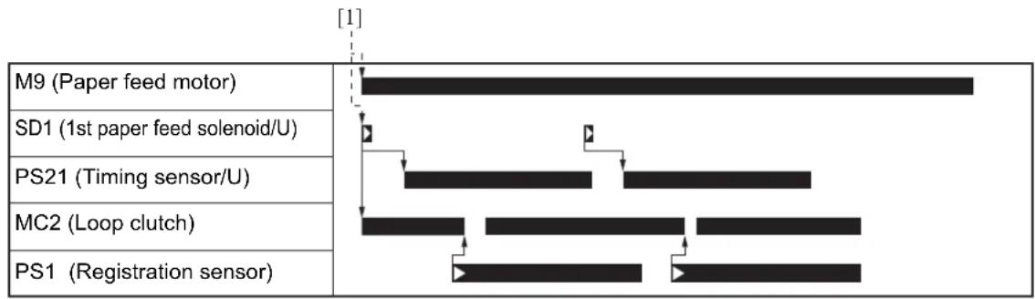
flowchart
graph TD
    A["M9 (Paper feed motor)"] --> B["1"]
    C["SD1 (1st paper feed solenoid/U)"] --> D["2"]
    E["PS21 (Timing sensor/U)"] --> F["3"]
    G["MC2 (Loop clutch)"] --> H["4"]
    I["PS1 (Registration sensor)"] --> J["5"]
[1] START button (ON)
6.2.3 Remaining paper detection control
Since the operation is the same for both the tray 1 and the tray 2, the explanation is given of the tray 1 only.
The remaining paper quantity is detected by the PS9 (Tray set sensor/U). As the remaining paper is getting reduced, the actuator provided on the rear side of the tray starts to ratate gradually as shown in the drawing. The PS9 turns on and off each time it passes through a slit. The remaining paper quantity is detected by counting the number of ON/OFF's after the installation of the tray.
0 count: Full 1 count: Medium 2 counts: Low
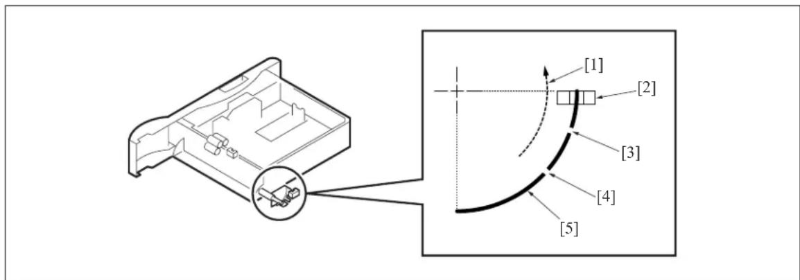
text_image
[1] [2] [3] [4] [5][1] Rotating direction when the paper up/down plate is going up.
[3] Slit 1
[4] Slit 2
[2]PS9 (Tray set sensor/U) [5]Actuator
6.2.4 Paper size detection
The paper size in the tray is detected by the CB (Main body control board), using signals sent from the PFDB/U (Paper feed detection board/U) and the PFDB/L (Paper feed detection board/L).
The paper size in the tray is set by the SW1 of the PFDB/U and the PFDB/L, and the CB detects a switch signal according to the position of the SW1. The table below shows the relationship between the switch signal and the paper size.
For metric area
| Paper size Switch | signal | ||||
| Tray 1 Tray 2 SIZE A S | SIZE B SIZE | C SIZE D | |||
| 8.5 x 14 11 | x 17 | ||||
| B5 B5 O | |||||
| B4 B4 O | |||||
| A5R A5R O | O | ||||
| A4 A4 O | |||||
| A4R A4R O | O | ||||
| F4 | A3 O | O | |||
| 5.5 x 8.5R | F4 | O | O | O | |
| 8.5 x 11 | 8.5 x 11 | O | |||
| 8.5 x 11R | 8.5 x 11R | O | O | ||
For inch area
| Symbol | Name Function or method | |
| [1]Fixing pressure roller Fixing of toner by pressureSilicon rubber + PFA tube | ||
| [2]Fixing heat roller Toner fixing by means of heatAluminum + PFA coatingTemperature setting:Idling: 376 to 369°FWhile in copy operation - Other than when feeding paper by the by-pass tray in the single sided copy mode: 381°FWhile in copy operation - When feeding paper by the bypass tray in the single sided copy mode (by selecting the type of paper)Thick paper mode 1: 381 + 50°FThick paper mode 2: 381 + 50°FThin paper: 381 - 50°F (Except the 7145)Other than the above: 381°FCopying - 381 - 41°F, when a double sided copy is being made.Low power mode: 185°F (can be changed in the 25 mode) | ||
| Symbol | Name | Function or method |
| [3]TH2 | (Fixing temperature sensor/2) | Detection of temperature at the edge (front side) of the fixing heating rollerContact type |
| [4]TH1 | (Fixing temperature sensor/1) | Detection of temperature at the center of the fixing heating rollerContact type |
| [5]Cleaning web Cleaning of the fixing heat rollerWeb wind-up method | ||
| [6]Fixing cleaning roller Tension pressure on the cleaning webSpring pressure | ||
| [7] | TS (Thermostat) | Protection of the fixing heat roller against high temperature abnormality (about 428°F)Contact type |
| [8]L3 | (Fixing heater lamp/2) Heating of the fixing heat roller (Sub)AC drive | |
| [9]L2 | (Fixing heater lamp/1) Heating of the fixing heat roller (Main)AC drive | |
| [10]Fixing guide Paper conveyance guide, pressure/release of the fixing pressure roller | ||
| [11]PS2 | (Fixing exit sensor) Detection of paper at the fixing unit exitPhotosensor + actuator | |
| [12]Neutralizing brush Neutralizing of paper that is exitedNeutralizing by means of a brush | ||
| [13]Fixing claw Separation of paper from the fixing heat rollerSpring pressure type (6 pcs.) | ||
| M11 Fixing motor Driving of the fixing heat roller and the ADU conveyance roller/1DC brushless motor, PLL control | ||
| SD4 Cleaning web solenoid Driving of the cleaning web24V drive | ||
| FCB | Fixing control board | Prevention of noise leak in the drive power for L3 (Fixing heater lamp /2)220V system only |
7.2 Operation
7.2.1 Fixing temperature control
The CB (Main body control board) uses the TH1 (Fixing temperature sensor/1) and the TH2 (Fixing temperature sensor/2) to detect the temperature of the fixing heating roller, and turns on and off the L2 (Fixing heater lamp/1) and the L3 (Fixing heater lamp/2) separately through the DCPS (DC power source) to maintain both the TH1 and the TH2 at the specified temperature.
A. Warm-up
The CB (Main body control board) turns on the fixing heater lamp circuit within the DCPS (DC power source) immediately after the SW2 turns on, and keeps the L2 (Fixing heater lamp/1) and L3 the (Fixing heater lamp/2) turned on until the fixing heat roller reaches the specified temperature.
Once warm-up has completed, the CB switches the L2 and the L3 on and off so that the fixing heat roller can be maintained to the set temperature for idling.
- Warm-up time: 30 seconds or less (at the room temperature of 68^ ) (7145)
- Warm-up time: 19 seconds or less (at the room temperature of 68^ ) (7235/7228/7222)
7.2.2 Cleaning web control
For each output of paper, the cleaning web is let off to be wound up.
The SD4 (Cleaning web solenoid) turns on based on the output of the PS2, causing the cleaning web to be driven to start a wind-up operation.

flowchart
graph TD
    A["PS2 (Fixing exit sensor)"] --> B["SD4 (Cleaning web solenoid)"]
    B --> C["-[1"][2]]
    C --> D["Interval"]
    D --> E["Interval"]
    style A fill:#f9f,stroke:#333
    style B fill:#ccf,stroke:#333
    style C fill:#cfc,stroke:#333
    style D fill:#fcc,stroke:#333
[1] START button (ON)
[2] 100 msec


8. ADU/PAPER EXIT SECTION
8.1 Composition
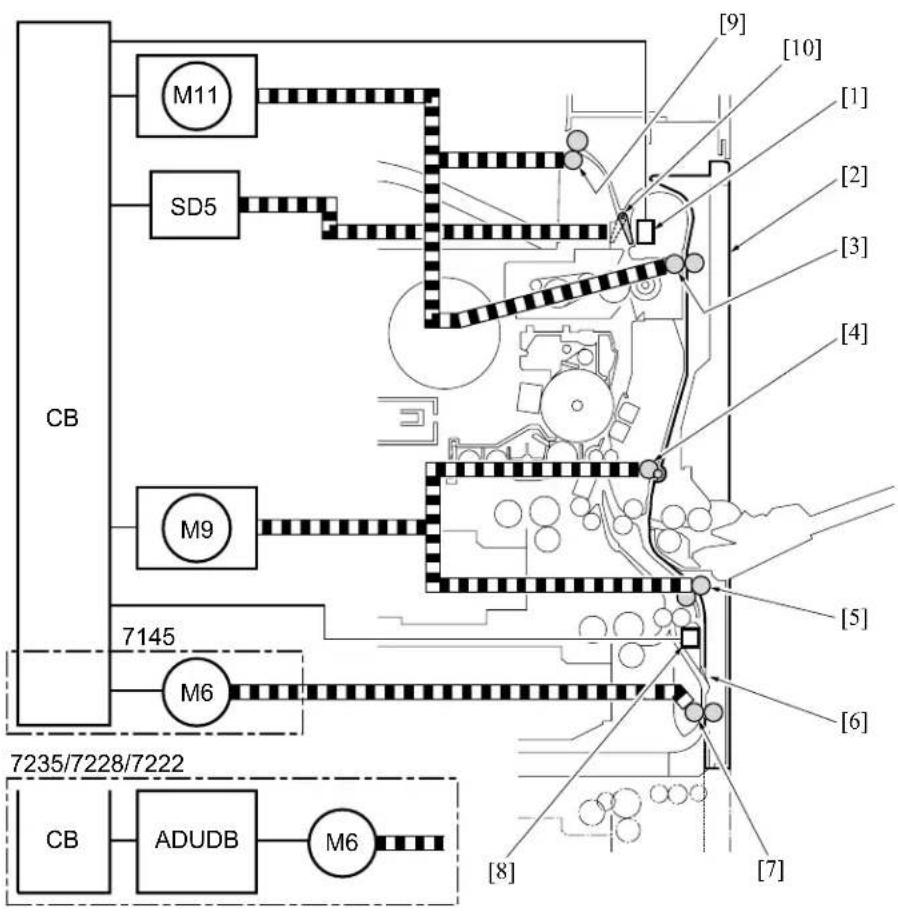
flowchart
graph TD
    A["CB"] --> B["M11"]
    A --> C["SD5"]
    A --> D["M9"]
    A --> E["7145"]
    A --> F["M6"]
    G["7235/7228/7222"] --> H["CB"]
    I["ADUDB"] --> J["M6"]
    K["0-9"] --> L["0-9"]
    M["10"] --> N["10"]
    O["1"] --> P["1"]
    Q["2"] --> R["2"]
    S["3"] --> T["3"]
    U["4"] --> V["4"]
    W["5"] --> X["5"]
    Y["6"] --> Z["6"]
    AA["7"] --> AB["7"]
    AC["8"] --> AD["8"]
| Symbol | Name Function or method | |
| [1]PS2 (Fixing exit sensor) Detection of paper at the fixing unit exitPhotosensor + actuator | ||
| [2]ADU unit (ADU door) Paper conveyance while in double sided copyJam removal while in double sided copy | ||
| [3]ADU conveyance roller/1 Paper conveyance through the ADU entranceMotor drive | ||
| [4]Decurler roller (7145)Conveyance roller (7235/7228/7222) | Paper conveyance through the ADU intermediate section and the correction of paper curling (7145)Paper conveyance through the ADU intermediate section (7235/7228/7222)Motor drive | |
| [5]ADU conveyance roller/2 Paper conveyance through the ADU intermediate sectionMotor drive | ||
| [6]Switching sheet Switching of conveyance path at the paper reverse sectionSwitching by means of the elasticity of the PET sheet | ||

| Symbol | Name | Function or method |
| [7]ADU roller | Paper conveyance through the ADU exit and switching of the conveyance directionMotor drive | |
| [8]PS4 (ADU sensor) Detection of paper at the ADU exitPhotosensor + actuator | ||
| [9]Paper exit roller Paper exit | Motor drive | |
| [10]Switching guide Switching of the paper exit path at the fixing unit exitSolenoid drive | ||
| ADUDB *1 | ADU drive board Driving of the M6 (ADU motor) | |
| M6 ADU motor Driving of the ADU motorStepping motor | ||
| M9 Paper feed motor Driving of the decurler roller (7145 only) and the ADU conveyance rollers/2DC brushless motor, PLL control | ||
| SD5 ADU gate solenoid Pressure and release of the switching guide24VDC drive | ||
| M11 Fixing motor Driving of the paper exit rollerDC brushless motor, PLL control | ||
*1 Except the 7145

8.2 Operation
8.2.1 Switching control of the paper exit/ADU conveyance path
A. Straight paper exit path
The straight paper exit path is applicable when a single side is copied as well as after the back side copy of paper is completed in the double sided copy mode.

text_image
[8] [7] [1] [2] [3] [4][5][6][1] Switching guide (SD5 OFF)
[2] PS2 (Fixing exit sensor)
[3] ADU conveyance driven roller/1
[4] ADU conveyance roller/1
[5] Fixing pressure roller
[6] Fixing heat roller
[7] Paper exit driven roller
[8] Paper exit drive roller
B. ADU conveyance path
The ADU conveyance path is applicable after the front side copy is completed in the double sided copy mode.

text_image
[8] [7] [1] [6] [2] [3][4][5][1]PS2 (Fixing exit sensor) [5]Fixing heat roller
[2] ADU conveyance driven roller/1
[6] Switching guide (SD5 ON)
[3] ADU conveyance roller/1
[7] Paper exit driven roller
[4]Fixing pressure roller [8]Paper exit drive roller
C. Straight paper exit operation (single sided 3 copies)
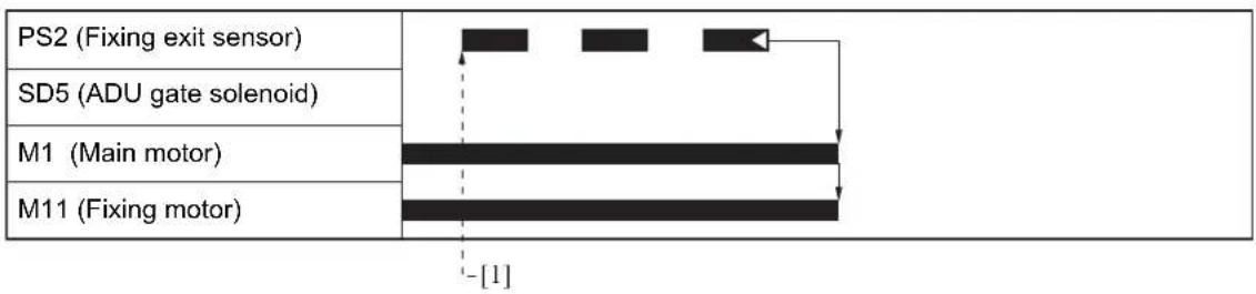
flowchart
graph TD
    A["PS2 (Fixing exit sensor)"] --> B["Main Motor"]
    C["SD5 (ADU gate solenoid)"] --> B
    D["M1 (Main motor)"] --> B
    E["M11 (Fixing motor)"] --> B
    B --> F["-> [1"]]
    style B fill:#000,stroke:#000,color:#fff
    style F stroke-dasharray: 5 5
[1]1st paper exit
D. ADU conveyance operation (double sided 3 copies)
2

flowchart
graph TD
    A["MC2 (Loop clutch)"] --> B["PS2 (Fixing exit sensor)"]
    B --> C["SD5 (ADU gate solenoid)"]
    C --> D["M1 (Main motor)"]
    D --> E["M11 (Fixing motor)"]
    style A fill:#f9f,stroke:#333
    style B fill:#ccf,stroke:#333
    style C fill:#cfc,stroke:#333
    style D fill:#fcc,stroke:#333
    style E fill:#cff,stroke:#333
    subgraph Time
        direction LR
        L1["->"] --> L2["->"]
        L2 --> L3["->"]
        L3 --> L4["->"]
        L4 --> L5["->"]
        L5 --> L6["->"]
        L6 --> L7["->"]
        L7 --> L8["->"]
        L8 --> L9["->"]
        L9 --> L10["->"]
        L10 --> L11["->"]
        L11 --> L12["->"]
        L12 --> L13["->"]
        L13 --> L14["->"]
        L14 --> L15["->"]
        L15 --> L16["->"]
        L16 --> L17["->"]
        L17 --> L18["->"]
        L18 --> L19["->"]
        L19 --> L20["->"]
        L20 --> L21["->"]
        L21 --> L22["->"]
        L22 --> L23["->"]
        L23 --> L24["->"]
        L24 --> L25["->"]
        L25 --> L26["->"]
        L26 --> L27["->"]
        L27 --> L28["->"]
        L28 --> L29["->"]
        L29 --> L30["->"]
        L30 --> L31["->"]
        L31 --> L32["->"]
        L32 --> L33["->"]
        L33 --> L34["->"]
        L34 --> L35["->"]
        L35 --> L36["->"]
        L36 --> L37["->"]
        L37 --> L38["->"]
        L38 --> L39["->"]
        L39 --> L40["->"]
        L40 --> L41["->"]
        L41 --> L42["->"]
        L42 --> L43["->"]
        L43 --> L44["->"]
        L44 --> L45["->"]
        L45 --> L46["->"]
        L46 --> L47["->"]
        L47 --> L48["->"]
        L48 --> L49["->"]
        L49 --> L50["->"]
        L50 -->|[-] | M1
    end
    style M1 fill:#f9f,stroke:#333
    style M11 fill:#f9f,stroke:#333
    style M12 fill:#f9f,stroke:#333
[1] 1st paper exit for the front side
[2] 1st paper exit for the back side
8.2.2 ADU conveyance control

When a sheet of paper, the front of which has been printed in the double sided mode is conveyed to the ADU unit, it is further conveyed to the ADU roller by the decurler roller (7145) or conveyance roller (except the 7145) and the ADU conveyance rollers/2 which are in turn driven by the M9 (Paper feed motor).
8.2.3 Paper reverse control
A. Paper reverse path

(1) When conveying paper
When a sheet of paper is conveyed from the ADU conveyance roller/2, it is further conveyed to the ADU roller by pushing the switching sheet open.

text_image
[9] [8] [7] [6] [5] [1] [2] [3] [4] 7322ma2006[1]ADU conveyance driven roller/2 [6]ADU roller
[2]ADU driven roller [7]Switching sheet
[3] Conveyance path when DB is provided
[4]DB [9]ADU conveyance roller/2
[5]Conveyance path when DB is not provided
[8] PS4 (ADU sensor)


(2) When paper reverse
Paper that has been conveyed is sent back by means of the reverse rotation of the ADU roller. At this time, the switching sheet uses its own elastic power to block the conveyance path to the ADU conveyance roller/2, and the paper is conveyed to the loop roller of the tray 2. As a result, the paper is turned inside out to be copied on the back side after passing through the same route as that for the paper sent from the tray 2.
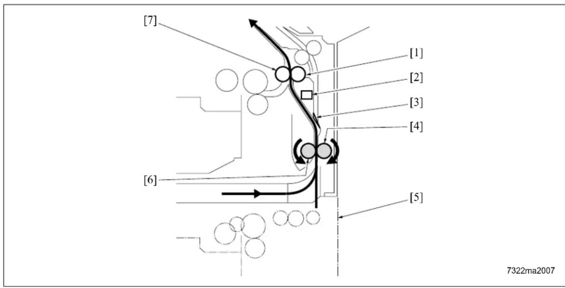
text_image
[7] [1] [2] [3] [4] [6] [5] 7322ma2007[1]Loop roller [5]DB
[2]PS4 (ADU sensor) [6]ADU roller
[3]Switching sheet [7]ADU conveyance roller/2
[4]ADU driven roller

B. Paper reverse operation (7145)

text_image
PS4 (ADU sensor) M6 (ADU motor) F 600mm/s 230mm/s R 230mm/s M9 (Paper feed motor) - [1][2][3][4][5][6][1] Start of 1st paper conveyance
[2] Start of reverse operation of 1st paper
[3] Start of 2nd paper conveyance
[4] Start of reverse operation of 2nd paper
[5] Start of 3rd paper conveyance
[6] Start of reverse operation of 3rd paper

C. Paper reverse operation (7235/7228/7222)

text_image
PS4 (ADU sensor) M6 (ADU motor) F 600mm/s *1 R *1 M9 (Paper feed motor) [1][2][3][4][5][6] 7322ma2013*1 165mm/s (7235) 140mm/s (7228/7222)
[1] Start of 1st paper conveyance
[2] Start of reverse operation of 1st paper
[3] Start of 2nd paper conveyance
[4] Start of reverse operation of 2nd paper
[5] Start of 3rd paper conveyance
[6] Start of reverse operation of 3rd paper
9. INTERFACE SECTION
9.1 Composition
In the case of the 7145
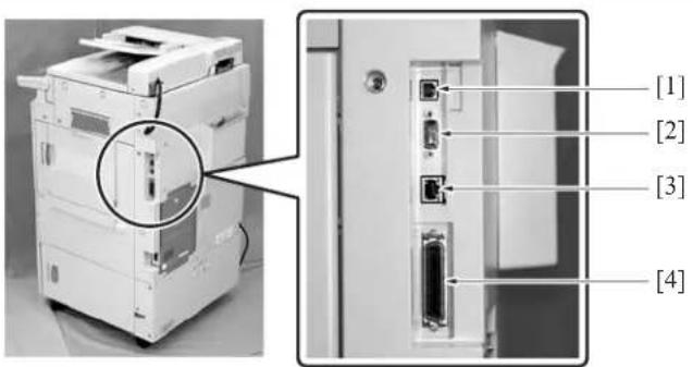
text_image
[1] [2] [3] [4]In the case of the 7235/7228/7222

text_image
[2] [4] [3] [1]| Symbol | Name Function or method | |
| [1] | Serial port (USB TypeB) | For ISW of copier/FAX, For serial output of the printerVer. 1.1 |
| [2] | Serial port (RS-232C) For KRDS communicationD-SUB 9-pin connector | |
| [3] | RJ45 Ethernet port Port for network | |
| [4] | Parallel port(IEEE1284 (Compatible,Nible, ECP)) | For ISW of copier/FAX/printerFor parallel output of the printer36-pin parallel interface |
10.NETWORK SECTION
10.1 Composition
| Item Function name Function Purpose Remarks | ||||
| TCP/IP service Arp | Obtain IP address | |||
| BootPO Obtain IP address | ||||
| DHCP O Obtain IP address | ||||
| DNS O Settle IP address | ||||
| FTP Client O Scan to FTP | ||||
| FTP Server O Scan to Box | ||||
| IPP | O | Support Ver. 1.0 | ||
| LPD/LPR | O Print | |||
| Raw Socket | O Print | Default port number = 9100 | ||
| SMTP | O Scan to Email | |||
| POP O For POP before SMTP | ||||
| POP before SMTP | O | Authorization of SMTP server access | ||
| HTTP 1.1 | O WebUtility | |||
| SNMP v1 (SNMP over TCP) | O MIB access | |||
| SNMP v1 (SNMP over IPX) | O MIB access | |||
| Telnet | X | |||
| SLP | X | |||
| Netware service | Bindery | O Print | ||
| NDS (including simultaneous support of Bindery) | O Print | |||
| PServer mode O | ||||
| RPrinter/NPrinter mode | O | |||
| NDPS (Gateway) | O Print | Corresponding in general purpose Gateway | ||
| PCONSOLE /NWAD-MIN, interchangeable | O | |||
| Frame Type (802.3, 8-02.3, 802.3 SNAP, Ethernet II) | O MAC frame corresponding | |||
| AppleTalk service | EtherTalk PAP | O | ||
| MS Network service | SMB over NetBEUI | X | ||
11. OTHER CONTROLS
11.1 Parts Energized When the Main Power Switch is OFF

text_image
CBR1 SW1 AC(H) NF DCPS AC(N) CBR2The following components are powered regardless of whether the SW1 (Main power switch) is on or off, provided that the power cord remains plugged in.
A. CBR 1 and CBR 2 (Circuit breakers/1 and /2)
The circuit breakers serve to protect internal components against damage from short circuit. If current exceeds the specified value, the circuit breaker(s) will go off, cutting the power to the system.
B. NF (Noise filter)
This filter reduces noises that enter through the power line.
C. DCPS (DC power source)
This supplies power to each unit, and also controls the ON/OFF state of the fixing heater lamp.
11.2 Components Operated When the Power Switch is ON
11.2.1 Components operated when the SW1 (Main power switch) is on
In the case of the 7145
2
flowchart
graph LR
    SW1 --> DCPS
    DCPS --> DCPSD["+24VDC"]
    DCPSD --> DCPSB["+5VDC"]
    DCPSD --> DCPSC["+12VDC"]
    DCPSC --> DCPSD
    DCPSD --> DCPSB["SCB"]
    DCPSB --> DCPSD
    DCPSB --> DCPSC
    DCPSB --> DCPSD
    DCPSD --> DCPSB
    DCPSB --> DCPSC
    DCPSB --> DCPSD
    DCPSD --> DCPSB
    DCPSB --> DCPSC
    DCPSB --> DCPSD
    DCPSD --> DCPSB
    DCPSB --> DCPSC
    DCPSD --> DCPSB
    DCPSB --> DCPSC
    DCPSD --> DCPSB
    DCPSB --> DCPSC
    DCPSD --> DCPSB
    DCPSB --> DCPSC
    DCPSD --> DCPSB
    DCPSB --> DCPSC
    DCPSD --> DCPSB
    DCPSB --> DCPSC
    DCPSD --> DCPSB
2
Setting the SW1 (Main power switch) to the ON position supplies AC power to the DCPS (DC power source) which in turn supplies +12DVC, -12VDC, and +5DVC to the SCB (System control board). The DCPS also supplies +5DVC to the OB (Operation board) through the SCB.
When the PTC (Internal heater) is provided as an option for service parts, according to the setting of the 25 mode DIP SW16-2, +24VDC is supplied to the PTC (Heater) from the DCPS (DC power source).
If options such as a printer controller (IP-432) and/or fax control board (FK-102 Type A/FL-102) are installed, +12VDC, -12VDC and +5VDC are also supplied to these options through the SCB (System control board).
In the automatic start-up mode, the same operation is made consecutively as when the SW2 (Sub power switch) is turned on according to the discretion of the SCB (System control board).
2

In the case of the 7235/7228/7222

flowchart
graph LR
    SW1 --> DCPS
    DCPS --> DCPSD["+12VDC +5VDC"]
    DCPSD --> SCB
    SCB --> OB
    OB --> PSW2B["SW2"]
    SCB --> IP424["IP-424 (OPTION)"]
    SCB --> FK103FL103["FK-103/FL-103 (OPTION)"]
    SCB --> Sub_SW["SUB_SW"]
    DCPSD --> PTC["PTC (OPTION)"]
    style DCPS fill:#f9f,stroke:#333
    style SCB fill:#ccf,stroke:#333
    style OB fill:#cfc,stroke:#333
    style IP424 fill:#fcc,stroke:#333
    style Sub_SW fill:#ffc,stroke:#333
    style SW2B fill:#fcc,stroke:#333
    note right of SW1: SW1
    note right of 7322ma2021

Setting the SW1 (Main power switch) to the ON position supplies AC power to the DCPS (DC power source) which in turn supplies +12DVC and +5DVC to the SCB (System control board). The DCPS also supplies +5DVC to the OB (Operation board) through the SCB.
When the PTC (Internal heater) is provided as an option for service parts, according to the setting of the 25 mode DIP SW16-2, +24VDC is supplied to the PTC (Heater) from the DCPS (DC power source).
If options such as a printer controller (IP-424) and/or fax control board (FK-103/FL-103) are installed, +12VDC and +5VDC are also supplied to these options through the SCB (System control board). However, when the LAN cables are not connected with none of these options provided, a part of the section within the SCB (System control board) is not supplied with +5 VDC.
In the automatic start-up mode, the same operation is made consecutively as when the SW2 (Sub power switch) is turned on according to the discretion of the SCB (System control board).
11.2.2 Components operated when the SW2 (Sub power switch) is on

The SW2 (Sub power switch) is located on the PSW2B (Power SW2 board). Upon the SW2 on, an ON signal is sent from the SW2 to the SCB (System control board) through the OB (Operation board). As a result, the SCB sends a control signal to the DCPS (DC power source), thus causing the DCPS to supply +12VDC, -12VDC (7145 only) and +5VDC to all of the boards and options, including the CB (Main body control board).
The SCB (System control board) then sends to the DCPS (DC power source) a control signal that causes the DCPS to generate +24VDC. This 24VDC power is supplied to all of the drive boards and options.
11.3 Fan Control
11.3.1 Composition of the cooling fan
flowchart
graph TD
    A["DCPS"] --> B["CB"]
    C[" "] --> D[" "]
    E[" "] --> F[" "]
    G[" "] --> H[" "]
    I[" "] --> J[" "]
    K[" "] --> L[" "]
    M[" "] --> N[" "]
    O[" "] --> P[" "]
    Q[" "] --> R[" "]
    S[" "] --> T[" "]
    U[" "] --> V[" "]
    W[" "] --> X[" "]
    Y[" "] --> Z[" "]
| Symbol | Name Function or method | |
| FM1 DC power supply cooling fan Cooling of the DCPS (DC power source) | ||
| FM2*1 Fixing cooling fan Preventing the ends of the fixing roller from getting overheated | ||
| FM3 Internal dehumidifying fan/1 Prevention of internal dew condensation, removal of internal ozone, and prevention against internal temperature getting too high | ||
| FM4 Internal cooling fan/1 Cooling of the drum unit, the write unit and their surroundings | ||
| FM5 Developing suction fan Prevention against scattering of toner around the developing unit | ||
| FM6 Internal dehumidifying fan/2 Prevention of internal dew condensation, removal of internal ozone, and prevention against internal temperature getting too high | ||
| FM7*2 Internal cooling fan/2 Cooling of the interior of the developing unit | ||
| FM7*3 Polygon cooling fan Cooling of the M5 (Polygon motor) | ||
*1 7145/7235 only
*2 7145 only
*3 7235 only
11.3.2 Fan operation
A. Operation of fans other than FM4 (Internal cooling fan/1)
2

flowchart
graph TD
    M1["Main motor"] --> M3["Developing motor"]*2
    M3 --> FM1["DC power source fan"]
    FM1 --> FM2(Fixing cooling fan)*1
    FM2 --> FM3["Internal dehumidifying fan/1"]
    FM3 --> FM5(Developing suction fan)
    FM5 --> FM6["Internal dehumidifying fan/2"]
    FM6 --> FM7["Internal cooling fan/2"]*3
    FM7 --> FM7_Polygon cooling fan*4
    FM7 --> [1]
    FM7 --> [2]
    FM7 --> [3]
    FM7 --> [4]
7322ma2014
[1] START button (ON)
*1 Operation for a small sized paper (such as B5R, A5R, B6R, postcard, 5.5 x 8.5R, 16KR). For paper sizes other than these small ones, the fan turns on when the TH2 (Fixing temperature sensor/2) detects a temperature above 417^ , and turns off when it gets below 408^

*2 7145 only
In the case of the 7235/7228/7222, the operation of the fan, that is based on whether the M3 (Developing motor) turns ON or OFF while in the 7145, is based on whether the M1 (Main motor) turns ON or OFF.

*3 7145 only

*4 7235 only
B. Operation of FM4 (Internal cooling fan/1)
(1) ON/OFF timing
The FM4 (Internal cooling fan/1) is turned on when the machine-inside temperature sensor provided on the TCSB (Toner control sensor board) detects a temperature of 109^ F, and turned off when the temperature gets below 105^ F.
(2) Abnormality detection
The internal temperature sensor installed on the TCSB (Toner control sensor board) detects a temperature of 136^ F, error code F22-1 is displayed on the operation unit and the machine is stopped.
11.4 Operation Unit Control
11.4.1 Composition of operation unit
flowchart
graph TD
    A["SCB"] --> B["OB"]
    B --> C["SGND"]
    B --> D["SUB_SW"]
    C --> E["PSW2B"]
    D --> F["LCD"]
    D --> G["LCDB"]
    G --> H["INV2"]
    G --> I["PAKB"]
    I --> J["SP (OPTION)"]
| Symbol | Name Function or method | |
| SW2 S | Sub power switch Power switch for the operating sectionDoes not function when the SW1 (Main power switch) is off. | |
| PSW2B | Power SW2 board LED packaging to display the on/off status of the SW1 (Main power switch) | |
| LCD LCD Use to display various information | ||
| LCDB Display board Backlight for the LCD | ||
| INV2 Display inverter Inverter used to drive the LCD (Display board) | ||
| PAKB | Panel key board | Touch switch board used to directly select items displayed on the LCD |
| SP | Speaker | When an optional fax control board is installed, a monitor sound on the line while a call is being made. |
| OB | Operation board | Used to control the PSW2B (Power SW2 board), the LCD (Display board), the INV2 (Display inverter) and the PAKB (Panel key board), and also used to control the LED inside the OB and the ten-key |
11.5 Counter Control
11.5.1 Counter composition

flowchart
graph TD
    CB --> SCB
    CB --> TC
    CB --> PS2
    SCB --> OB
    TC --> TC(OPTION)
    TS["7145"] --> TC
    TS --> KC(OPTION)
    TS --> PS2
    OB --> TC(OPTION)
    TC(OPTION) --> TC
    style SCB fill:#f9f,stroke:#333
    style TS fill:#ccf,stroke:#333

| Symbol | Name Function or method | |
| OB Operation board Displays the number of copies by means of the LED. | ||
| TC Total counter(7145 provided as a standard equipment)(7235/7228/7222 optional) | Displays the total number of copies.This is a mechanical counter driven by an electric signal. | |
| KC Key counter (optional) A counter used to make copying unavailable after the specified number of copies is countedThis is a mechanical counter driven by an electric signal. | ||
| PS2 Fixing exit sensor Detects paper at the fixing exit. This information becomes a control signal source for each counter.Photosensor + actuator | ||
11.5.2 Counter operation
This machine uses the following two software counters to count the number of copies. However, the content of the number display counter on the OB (Operation board) may differ depending on the operating condition of the machine.
A. Paper feed counter
This counter increments when the 1st paper feed for the next copy comes ON.
B. Paper exit counter
This counter increments when the PS2 (Fixing exit sensor) goes ON → OFF.
C. Number display counter on the OB (Operation board)
| Normal operation Jam | |
| Indicator shows a count from the paper feed counter. | Indicator shows a count from the paper exit counter. |

Blank page
III DISASSEMBLY/ASSEMBLY
Caution:
- Make sure the power cord of the copier is unplugged from the power outlet before disassembly or assembly.
1. EXTERNAL SECTION
1.1 Replacing the Ozone Filter
A. Periodically replaced parts/cycle
• Ozone filter: Every 240,000 copies (7145)
- Ozone filter: Every 200,000 copies (7235/7228/7222)
B. Procedure
- Remove the 4 screws [1], and remove the scanner exterior/R [2].
Note:
- If an unusual noise is emitted when you open or close the bypass tray, clean the ADU door rib [3] with alcohol.

text_image
[1] [1] [2] [3]- Remove the ozone filter [1].
- Reinstall the above parts following the removal steps in reverse.
Note:
- When installing the ozone filter, take care not to break it.
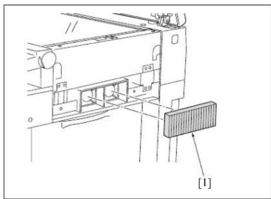
natural_image
Technical line drawing of a mechanical assembly with labeled component [1], no readable text or symbols present1.2 Replacing the Filter Cover Assembly & Suction Filter/A

A. Periodically replaced parts/cycle
• Suction filter/A: Every 120,000 copies (7145)
- Suction filter/A: Every 100,000 copies (7235/7228/7222)
- Filter cover assembly: Every 120,000 copies (7145)
- Filter cover assembly: Every 100,000 copies (7235/7228/7222)
B. Procedure
- Remove the screw [1], then remove the filter cover assembly [2].
- Remove the suction filter /A [3].
- Reinstall the above parts following the removal steps in reverse.
Note:
- When installing the suction filter/A, be sure to install it so that the white filter face is turned to the inside of the main body.
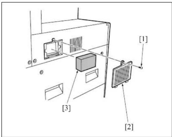
text_image
[1] [2] [3]Note:
- When an elevator tray unit is fitted, perform the following to access the filter section.
- While pressing [1], lift up [2], and pull out the elevator tray unit and the horizontal conveyance unit. Do not remove the finisher.
To remove the finisher, see [III. DISASSEMBLY/ASSEMBLY] of the finisher section.

text_image
[1] [2] 7145ma31302. DRIVE SECTION
2.1 Removing and Reinstalling the Motor Units (Main, Fixing, Feed, Developing)
Caution:
- Be sure to remove the drum unit from the main body before removing or reinstalling the main motor unit. If the drum unit is in place at this time, the drum will rotate when you install or remove the drum rotating plate, resulting in possible damage to the cleaning blade.
A. Procedure
- Remove the developing unit and drum unit from the main body.
- Remove the screw [1], and remove the cord cover/B [2].
- Remove the 2 screws [3], and remove the cord cover/A [4].
-
Remove the 9 screws [5], and remove the rear cover [6].
-
Remove the 2 screws [1], and remove the rear cover/R [2], the rear cover/L [3].
-
Remove the 3 screws [4], and remove the wire-bundle guide plate [5].
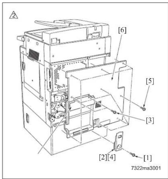
text_image
[6] [5] [3] [2][4] [1] 7322ma3001
text_image
[1] [2] [3] [4] [5]- Remove the 15 screws [1], and remove the board cover/D [2] (7145 only).
- Remove the 13 screws [3], and remove the board cover/A [4].
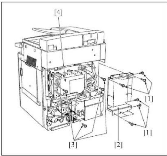
text_image
[4] [1] [3] [2] [1]- Remove the various wiring connectors from the SCB (System control board) [1].
Note:
- Be very careful when handling the ribbon cable connector from the SCB (System control board). See "2.4 Removing the ribbon cable" and "2.5 Installing the ribbon cable".
- Remove the 12 screws [2] (7145) or the 11 screws [3] (7235/7228/7222), and remove the system control board unit [4].

text_image
[1] [2][3] [2] [2][3] [2][3] [4] 7322ma3002-
Disconnect the connectors from each motor unit [1].
-
Remove the 4 screws [2], then remove each motor unit [3], [4] (7145 only), [5].
- Reinstall the above parts following the removal steps in reverse.
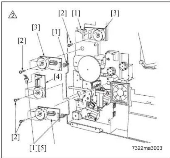
text_image
[2] [3] [1] [2] [4] [2] [1][5] [1] [1] [3] 7322ma30032.2 Replacing the Registration Clutch
Caution:
- Be sure to remove the drum unit from the main body before carry out the following procedure. If the drum unit is in place at this time, the drum will rotate when you install or remove the drum rotating plate, resulting in possible damage to the cleaning blade.
A. Procedure
- Remove the system control board unit.
- For removal procedure, see "2.1 Removing and reinstalling the motor units (main, fixing, feed, developing)".
-
Remove the set screw [1], and remove the drum rotating plate [2].
-
Remove the clutch connector [1].
-
Remove the E-ring [2]. Pull the registration clutch [3] toward you and rotate it to remove.

text_image
[1] [2]
text_image
[1] [2] [3]- Reinstall the above parts following the removal steps in reverse.
Note:
- When installing the registration clutch [1], be sure to set the groove of the clutch detent in the stopper [3].
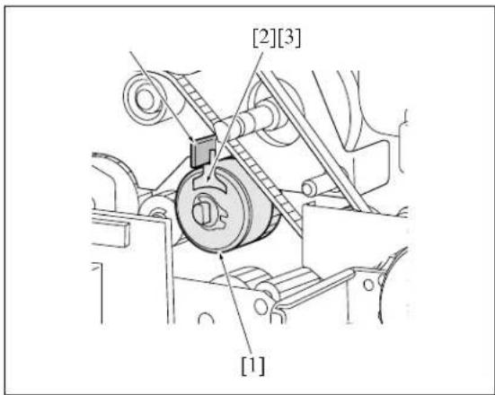
text_image
[2][3] [1]2.3 Replacing the Loop Clutch
A. Procedure
- Remove the system control board unit.
- For removal procedure, see "2.1 Removing and reinstalling the motor units (main, fixing, feed, developing)".
-
Remove the wire bundle from the clamp on the conveyance drive panel [1].
-
Remove the 2 E-rings [2], 3 screws [3] and 2 bearing [4], and remove the conveyance drive panel [1]. (Do not remove the rotation prevention screws on the clutch.)
-
Remove the E-ring [1], then remove the gear [2] and the connector [3], remove the gear [4] at the front, and then remove the clutch [5].
-
Reinstall the above parts following the removal steps in reverse.
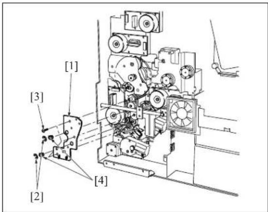
text_image
[1] [3] [2] [4]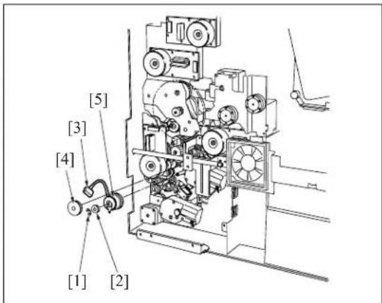
text_image
[1] [2] [3] [4] [5]2.4 Removing the Ribbon Cable
A. Procedure
- Move the lock lever [1] forward to release the lock, then pull out the ribbon cable [2].
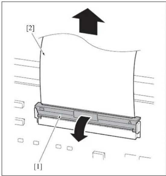
text_image
[2] [1]2.5 Reinstalling the Ribbon Cable
A. Procedure
- Move the lock lever [1] forward, then insert the ribbon cable [2] firmly into the connector while ensuring that the conductive face of the ribbon cable [3] is positioned on the opposite side of the lock lever.

text_image
[2] [1] [3]- Push back the lock lever [1] to lock the ribbon cable [2].

text_image
[2] [1]3. SCANNER SECTION
3.1 Screws That Must Not be Removed
Note:
- The paint-locked screws [1] must not be removed. Be sure that you do not remove these screws.
In the case of the 7145
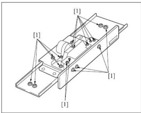
text_image
[1] [1] [1] [1]
In the case of the 7235/7228/7222
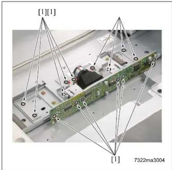
text_image
[1][1] [1] 7322ma30043.2 Adjusting the Angle of the Operation Unit
A. Procedure
- Remove the 2 screws [1].
- Remove the operating section stopper [2].
- Remove the 2 screws [3] for each position. And then install the angle adjustment member [4] in the specified position.
The angle adjustment member corresponds to 7 degrees for the right position and to 15 degrees for the left position. However, this is not used for the setting of 33 degrees. - Change the installation direction of the operating section stopper [2] and set it at the position for 7 or 15 degrees. However, this is not used for the setting of 33 degrees.
Note:
- The angle of the operation unit can be adjusted at the following 3 stages: However, the setting at 33 degrees is available only when combined with the paper exit tray.
- Install the operating section stopper [2].
6.Fasten the operation unit [5] with the 2 screws [1].
- Install the operating section stopper [2].
- Fasten the operation unit [5] with the 2 screws [1].
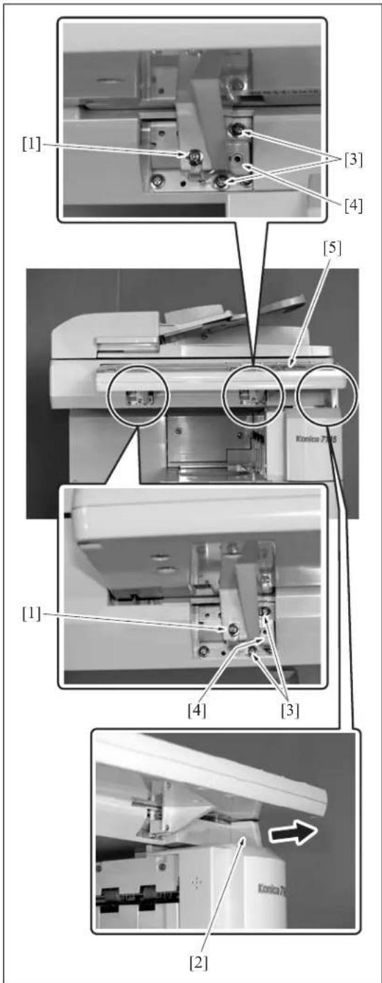
text_image
[1] [3] [4] [5] [1] [4] [3] [2] Konomics 7083.3 Removing the Operating Unit
A. Procedure
- Open the ADU door [1].
- Remove the screw [2] and remove the right side cover /F [3].
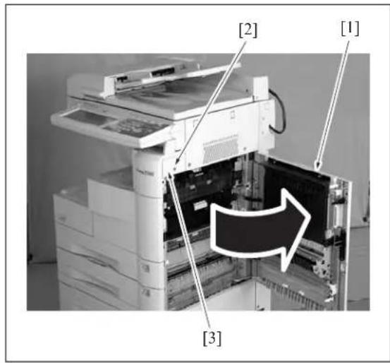
text_image
[1] [2] [3]- Remove the 2 angle adjusting screws [1], and remove the operating section stopper [3] while lifting up the operating section [2].
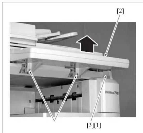
text_image
[2] [3][1]- Loosen the 2 screws [1] and remove the front cover [2] and the front door [3].

text_image
[2] [1] [3]- Remove the connector [1].
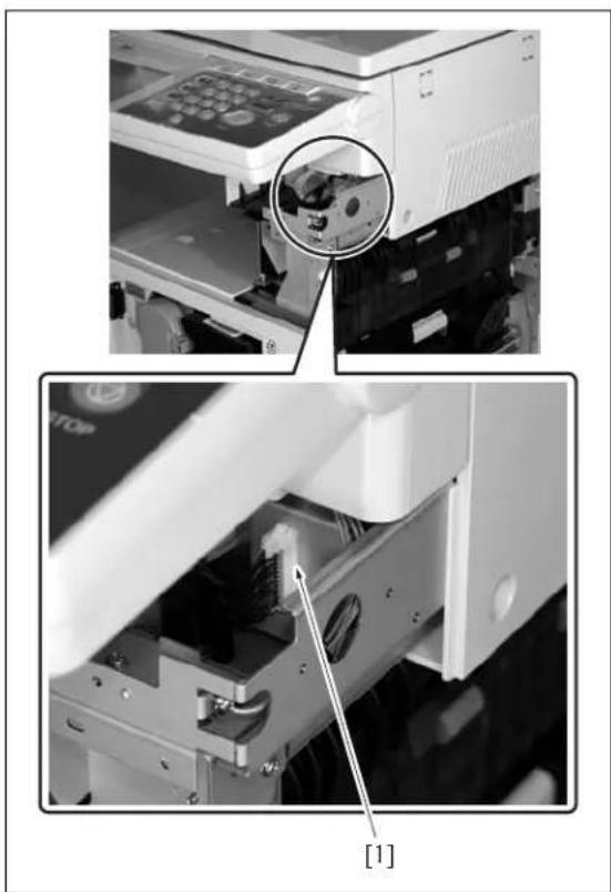
natural_image
Two-panel black-and-white photo showing a printer's internal components, including a close-up of the device and a close-up of the printer's internal structure (no visible text or symbols)- Remove the 3 screws [1], and remove the operating section [2] by pulling it out to this side.
- Reinstall the above parts following the removal steps in reverse.

text_image
[2] [1]3.4 Removing the Platen Glass/Slit Glass
When removing the platen glass, execute only the steps 1, 3, 7, 8 and 9 in the following procedure. For the slit glass, execute all of the steps 1 to 9.
A. Procedure
1.Open the RADF.
2. Remove the operation unit.
3. Remove the 4 screws [1] and remove the scanner exterior/R [2].
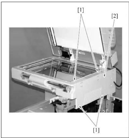
text_image
[1] [2] [1]- Remove the 4 screws [1] and remove the scanner exterior/L [2].
text_image
[2] [1] [1]- Remove the 7 screws [1] and remove the scanner exterior/F [2].
text_image
[1][1] [1][2] [1]- Remove the 2 screws [1] of the slit glass pressure plate and remove the slit glass [2].
- Loosen the screw [3] and slide the glass pressure plate [4] to the paper feed side.
- Lift up once the platen glass [5]. And then slide it to the paper feed side to remove it.
Note:
- Be careful not to stain the white reference plate attached to the back of the scale plate [6] provided on the paper feed side of the platen glass [5].
-
When the white reference plate gets smudged, wipe it thoroughly with a clean cloth.
-
Reinstall the above parts following the removal steps in reverse.
Note:
- When installing the platen glass [5], be sure to fasten it securely while pressing the glass pressure plate [4] to the platen glass [5].
- The slit glass is distinguished between the front and the rear. Be sure to set the slit glass [2] so that a black dot on its side comes in the rear right side when you see the 7145 from the front side. When attaching the slit glass holding plate with the 2 screws [1], tighten these screws while pressing the slit glass [2] onto the original glass [5] side.

text_image
[1] [5] [2][6] [3] [4]3.5 Removing and Reinstalling the CCD Unit
A. Procedure
- Remove the platen glass.
- Remove the 2 screws [1], and remove the photo sensor fastener [2].
- Remove the 8 screws [3], and remove the lens light blocking cover [4].
- Remove the 3 screws [5], and remove the ribbon cable cover [6].

text_image
[3] [2] [1] [5] [6] [5] [4] [3]- Remove the ribbon cable [2] from the ADB (A/D conversion board) [1].
Note:
- Be careful to avoid damage to the ribbon cable when removing it. When reinstalling it, be sure that it is securely in place.
- Remove the 4 screws [3], and remove the CCD unit [4].
- Reinstall the above parts following the removal steps in reverse.
text_image
[3][3][4] [1] [2] 7145ma3052Note:
- Be sure to perform image adjustment after installing the CCD unit. (See "I Adjustment" section.)
3.6 Replacing Exposure Lamp
Caution:
- Do not touch the exposure lamp's lamp area with bare hands.
A. Procedure
-
Remove the RADF.
-
For removing procedure, see the DF service manual.
- Remove the platen glass.
-
Remove the 4 screws [1], and remove the read cover/R [2].
-
Shift the exposure unit [1] to the center of the main body frame.
- Remove the 2 screws [2], and remove the auxiliary reflecting mirror [3].
- Remove the 1 connector [1] and 2 screws [2]. Tilt and remove the exposure lamp [3].
- Reinstall the above parts following the removal steps in reverse.
text_image
[2] [1] [1]
text_image
[2] [3] [1]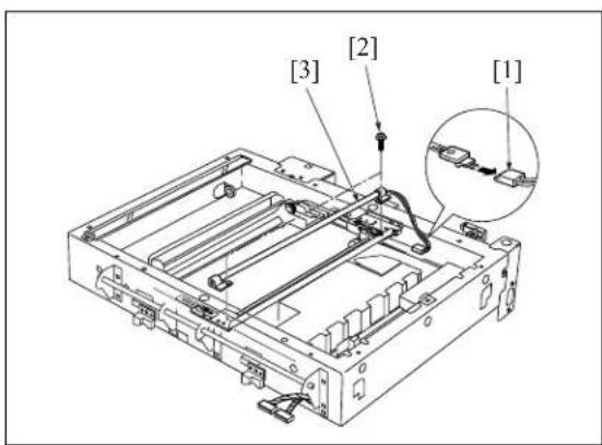
text_image
[3] [2] [1]3.7 Removing and Reinstalling the Exposure Unit
A. Removal procedure
- Remove the RADF.
- Remove the platen glass.
- Remove the scanner cover/R.
- Shift the exposure unit [1] to the center of the main body frame.
- The exposure unit [1] is fixed in place by set screws fastened to the exposure unit mount fittings/F [3], /R [4] (1 screw in each fitting). Remove the 2 screws [2].
- Tilt and slide the exposure unit [1] to remove it from the frame.
- Disconnect the exposure lamp [5] connector [6].
B. Installation procedure
- Fit the exposure unit into the main body.
- Insert the front exposure unit mount fitting/F [2], /R [3] into the corresponding slits in the exposure unit.
- Shift the V mirror unit [4] to the exit side. Through the front, insert the two optics unit positioning jig [5] so that they are at the installation location for the exposure unit. Pass the jig [5] through the V mirror unit [4] to fasten it in place. Position the exposure unit [1] by pushing it against the frame on the right side of the unit.
Note:
- Be sure to the use optics unit positioning jig when reinstalling the exposure unit.
- Fasten the exposure unit mount fittings/F, /R into place (1 screw in each fitting).
- Remove the optics unit positioning jig.
- Finish installation by reversing the sequence of the removal procedure.
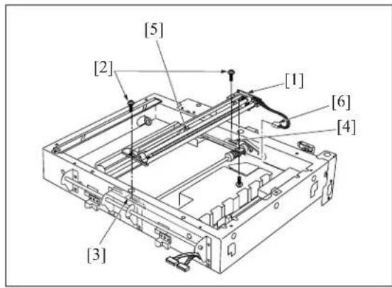
text_image
[5] [2] [1] [6] [4] [3]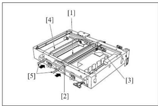
text_image
[1] [4] [3] [2] [5]3.8 Removing the Optics Wire
A. Procedure
- Remove the RADF.
- Remove the platen glass.
- Remove the scanner cover/R.
- Shift the V mirror unit [1] to the paper exit side. Through the front, insert the optics unit positioning jig so that it is at the V mirror attachment location. Pass the jig through the V mirror unit [1] to fasten the it in place.
- Remove the exposure unit [2].
- Detach the nuts [5] and washers [6] from the ends of the optical wires/F [3], /R [4], and remove the wires/F [3], /R [4].
- Remove the screws [7] holding the two drive pulley [8] bearings in place (two screws on each pulley), and remove the bearings [9].
- Remove the optical wires/F [3], /R [4] from the drive pulleys.
text_image
[1] [2] [4] [5] [6] [7] [8] [9] [3] [5]3.9 Installing the Optics Wire
A. Procedure
- Loosen the set screw of the drive pulley [1] on one side so that the drive pulley can rotate freely against the pulley shaft.
-
Fit the metal ball [3] (midway along each optical wire [2]) into the mount opening on the drive pulley [1]. Starting from this position, wind 6 times [4] around the outside and 5 times [5] around the inside.
-
Use the "F" exposure unit mount fitting (the fitting with the "F" printed on it) at the front, and use the "R" fitting at the rear.
- The end with the metal ball [7] at the tip winds around the inside of the pulley shaft [8].
- Wind so that the two ends of the wire come off the top of the pulley.
- After winding the wires [1], fasten them in place (with tape [6], etc.) so that they cannot come off.
Note:
- When winding wire around pulleys, be sure that the winds are close. Be careful to avoid overlap.
-
When changing the wire, be sure to use the optics unit positioning jig.
-
On the metal ball [1] side, pass the optical wire [2] so that it passes under the V mirror unit [3], through the paper exit side pulley [4], and through the inside pulley [5] on the V mirror unit. Hook the end of the wire onto the notch [6] on the frame.
-
On the right side, pass the wire so that it passes through the right side pulley [7], passes over the pulley [8] on the outside of the V mirror unit, and passes under the V mirror unit. Fasten the end to the right side frame with the nut [9] and washer [10].
text_image
[7] [8] [5] [4] [1] [3] [2] [6] [8] [6] [3] [1] [4] [5] [7] [8] [2] [3]
text_image
[1] [4] [3] [2] [8] [6] [2] [5] [7] [4] [5] [9] [10] [8]- Position the V-mirror unit by using the optics unit positioning jig.
- After temporary fastening, use a spring balancer to apply 1.3 \~ 1.7kg of tension to the front and rear optical wires in the arrow direction, then fully tighten the nuts [1].
- Fasten the set screw of the drive pulley which has been loosened.
- Using the optics unit positioning jig to install the exposure unit.
- Remove the optics unit positioning jig.
11.Slide the exposure unit two or three times to make sure that it works correctly. - Finish installation by reversing the sequence of the removal procedure.
text_image
[1] [1]4. WRITE UNIT
4.1 Removing and Reinstalling the Write Unit
Warning:
- Never supply power while the write unit is out of its proper installed position.
- Do not open the cover of the write unit while power is being supplied. Shining of the laser beam on the eye may cause blindness.
Note:
- When removing the write unit, take care to avoid touching with the write mirror and the dust proof glass. (Touching these areas may leave scratches and smudges.)
- When installing the write unit, confirm that the PET sheet at the end is seated correctly in the duct.
- After turning the main power switch OFF, wait at least two minutes before removing the write unit.
A. Procedure
- Open the front door and remove the developing unit and the drum unit.
- Remove the exit tray.
- Remove the front door.
- Remove the main body cover/FR [1], the main body cover/FL [2], the side cover/R [3], the filter cover assembly [4], the main body cover/U [5] and the main body assist cover [6].
text_image
[1] [2] [3] [4] [5] [6]- Remove the write cleaning knob [2] from the dust proof glass cleaning rod [1] and then puch the rod [1] to inside of main body.

text_image
[1][2]- Remove the 11 screws [1], and remove the write cover [2].
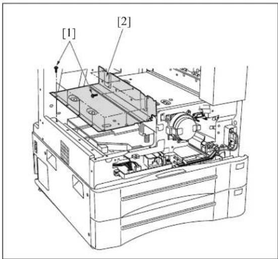
text_image
[1] [2]- Remove the two write unit mount pieces [2] (each is held in place by screw [1]).
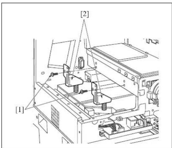
text_image
[1] [2]-
Disconnect the 3 connectors [1].
-
Remove the air duct [2].
-
Remove the 3 screws [3] (SEMS II: long screws), and remove the write unit [4] by pulling it to the paper exit side.
Note:
- When removing the write unit, take care to avoid touching with the write mirror and the dust proof glass.
In the case of the 7145

text_image
[1] [2] [3] [4]
In the case of the 7235/7228/7222
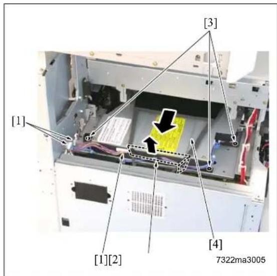
text_image
[1] [3] [1][2] [4] 7322ma3005- Reinstall the above parts following the removal steps in reverse.
Note:
- Reinstall the write unit while inserting the front edge of the cooling air guide sheet [1] into the specified position.
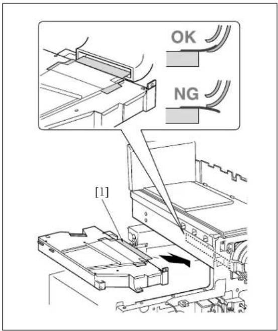
text_image
OK NG [1]5. DRUM UNIT
5.1 Removing and Reinstalling the Drum Unit

A. Periodically replaced parts/cycle
- Drum unit: Every 720,000 copies (7145)
- Drum unit: Every 600,000 copies (7235/7228/7222)
B. Procedure
- Remove the developing unit.
- Open the ADU door [1], and open the conveyance unit [2].
- Loosen the screw [3], and gently pull the drum unit [4] out toward you until it stops. Then tilt it slightly and remove it.
Note:
- When removing the drum unit, be sure to hold it at both ends to prevent a possible deformation of the drum unit.
• After removing the drum unit, close the drum cover and store the unit in a dark place. - During removal and reinstallation work, never rotate the drum in the wrong direction (in the direction opposite to the direction it moves during normal copying). Rotating the drum in the reverse direction may cause scratches to the cleaning blade.
-
When removing the drum unit, do not place your hand on the separation claw unit [5].
-
Reinstall the above parts following the removal steps in reverse.

text_image
[1] [2] [3] [4] [5]5.2 Removing and Reinstalling the Charging Corona Unit
A. Procedure
- Remove the drum unit from the main body.
- Set the unit so the drum is to the top.
- Remove the cleaning rod's [1] shaft stopper fitting [2], and pull out the cleaning rod [1].
-
Disconnect the connector [3] from the drum unit.
-
Remove the 2 screws [4] (7235/7228/7222 only).
-
Remove the back side (rear side) of the charging corona unit [5] in the arrow-marked direction [6] and remove it by sliding in the arrow-marked direction [7].
-
Reinstall the above parts following the removal steps in reverse.
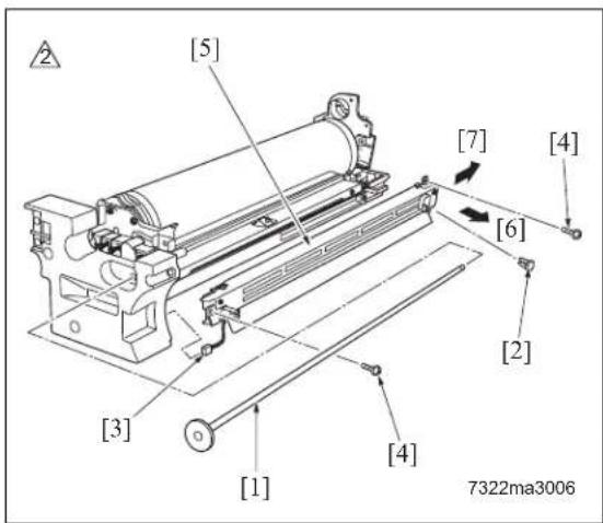
text_image
[5] [7] [4] [6] [2] [3] [1] [4] 7322ma3006Note:
- Be careful not to bend excessively the charging corona pressure spring.
5.3 Removing and Reinstalling the Charge Control Plate
A. Procedure
- Remove the drum unit from the main body.
- Remove the charging corona unit. Move the charging cleaning block to its home position (at the rear side).
- Remove the 2 charge control springs [1], and remove the charge control plate [2].
- To clean: tap lightly with a cloth soaked in drum cleaner, then use a blower brush to remove remaining debris.
- Reinstall the above parts following the removal steps in reverse.

text_image
[1] [2]Note:
- When reinstalling, be sure to set the charge control plate so that the spring held end is toward the front of the charging corona unit.
5.4 Replacing the Charging Wire
A. Procedure
- Remove the drum unit from the main body.
- Remove the charging corona unit. Move the charging cleaning block to its home position (at the rear side).
- Remove the charge control plate.
- Remove the 2 charging covers (charging cover/F [1], and charging cover/R [2]).
② 5.In the case of the 7145
Remove the 2 springs [3], and remove the 2 charging wires [4].
In the case of the 7235/7228/7222
Remove the 2 springs [3], and remove the 1 charging wire [4].
-
To install the replacement wire: first fasten the rear end of the wire to the unit, then pass the wire through the charging cleaning block and fix it in place with the spring. Then complete the installation by reversing the steps above.
-
Finish installation by reversing the sequence of the removal procedure.
5.5 Removing and Reinstalling the Drum
A. Periodically replaced parts/cycle
• Drum: Every 240,000 copies (7145)
• Drum: Every 200,000 copies (7235/7228/7222)
B. Removing procedure
- Remove the drum unit from the main body.
- Remove the charging corona unit from the drum unit.
- Remove the screw [1] and the fixing material [2], and pull out the drum shaft [3].
When the drum shaft is hard to pull out, knock lightly at the rear end of the drum shaft.

text_image
[4] [1] [2] [3]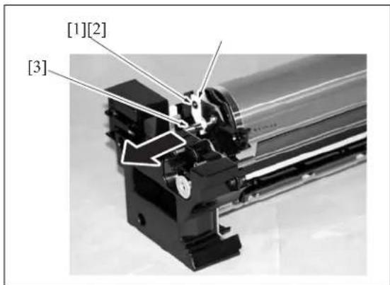
text_image
[1][2] [3]- Remove the 2 screws [1], and remove the drum bearing [2].
- Remove the 2 semicircular seal blocks [3] (one on each end of the drum).
- To remove the drum, lift it up and out from the front side.
Note:
• Take care to avoid scratching the drum's light sensitive areas and the cleaning blade. Do not touch these areas with bare hands.
- When removing or installing, never allow the drum to bump against the plate-metal part of the cleaning blade.
- If you are going to place the drum in storage, be sure to place a cover on the drum (to cut off light to it) and store it in a dark place.
- When removing the drum unit, do not place your hand on the separation claw unit.

text_image
[3] [1] [2]C. Installing procedure
Note:
- Be sure that the toner collection sheet makes contact with the entire span of the drum, with no gaps.
- Coat the entire surface of the drum with setting powder.
- Fit the long convex end [2] of the drum [1] into the rear side of the unit, then set the drum down into the unit. Reattach the two seal blocks [3] (one at each end of the drum).
- Reattach the drum bearing [4]. Fasten it into place with the 2 set screws [5].
- Insert the drum shaft and fasten the hold-down member [4] with a screw. Be sure to attach the hold-down member securely as shown in the drawing right.
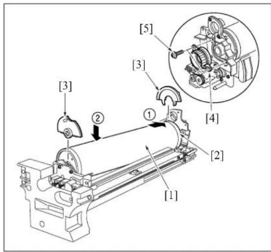
text_image
[3] [2] [1] [5] [3] [4] [2]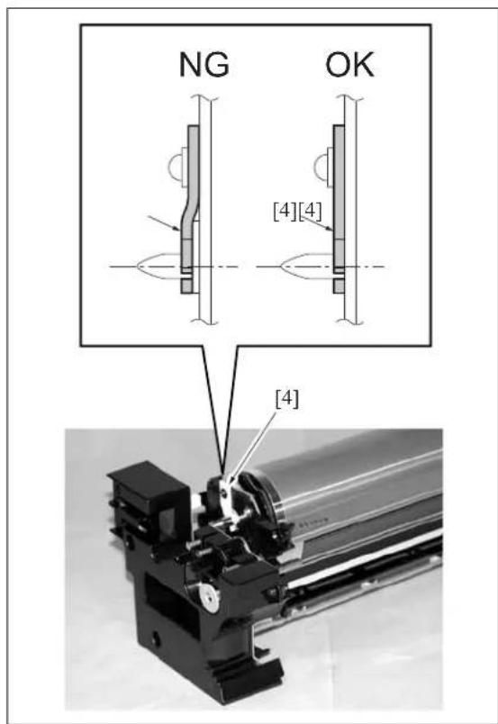
text_image
NG OK [4][4] [4]- Using the jig [1] included on the drum unit cover, rotate the drum clockwise and confirm that there are no gaps in the setting powder coat, and that the toner collection sheet and cleaning blade are smooth, etc.
- Finish installation by reversing the sequence of the removal procedure.
Note:
- Before installing the drum and cleaning blade (regardless of whether new or used), be sure to coat these with setting powder. Apply the powder around the entire drum, and on both sides of the blade.
- If you have coated setting powder onto the drum: Before installing the drum unit back into the main body, use an alcohol-soaked cloth to remove stray powder from the sensor surface on the toner control sensor board. This is necessary to ensure that accurate toner density readings are obtained.
- Be sure that the drum is oriented correctly before installing it. The drum should be positioned so that the convex end of the longer section comes at the back.
- After installing a new drum, be sure to reset the drum-related counters in the 36 mode.
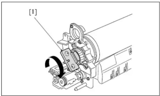
text_image
[1]

5.6 Removing and Reinstalling the Separation Claw
A. Procedure
- Remove the drum unit from the main body.
- Remove the drum from the drum unit.
- Disconnect the relay connector [1].
- Remove the separation rock spring [2].
- Remove the 2 positioning screws [3], the 2 collars [4] and the 2 spacer [5], and then remove the separation claw unit [6].
Note:
- While removing or installing the claw, be careful to avoid damage to the drum.
- Pull out the separation fulcrum shaft [2] while pressing down the claw [1] and remove the 2 separation claws [3].
- Reinstall the above parts following the removal steps in reverse.
Note:
- When installing the claw, be sure that it is correctly oriented and positioned.
- Do not touch the cleaning blade or the drum's light sensitive areas with bare hands.
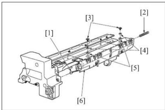
text_image
[1] [3] [2] [4] [5] [6]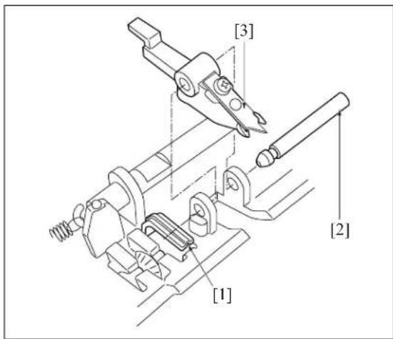
text_image
[1] [2] [3]5.7 Removing and Reinstalling the Transfer and Separation Corona Unit
A. Periodically replaced parts/cycle
• Transfer corona unit: Every 480,000 copies (7145)
• Transfer corona unit: Every 400,000 copies (7235/7228/7222)
B. Procedure
- Open the ADU door.
- Pull the conveyance unit [1] toward you to open.
- Push the rear catch of the transfer/separation corona unit [2], then remove the unit.
- Reinstall the above parts following the removal steps in reverse.
Note:
- When installing the Transfer/Separation corona unit, be sure that the cleaning material is in home position at the rear side.

text_image
[1] [2]5.8 Replacing the Transfer and Separation Wires
Note:
- Do not remove the screw that must not be removed [2] of the paper entrance guide plate [1].
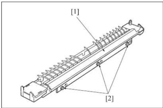
text_image
[1] [2]A. Procedure
- Remove the transfer and separation corona unit from the main body.
- Use a tweezers to remove the hook [1] from the transfer and separation corona unit. Then remove the plunging prevention plate [2].

text_image
[2] [1]- Remove the spark arrestor plates/F [1], /R [2].
text_image
[1] [2]- Move the cleaning block to home position, and remove the top covers [1] from the cleaning block.
- Remove the spring [2] from each wire, and remove the wires [3].
Note:
- When removing the wire, be careful that the wire holding rubber that is in touch with the V-shaped rack [4] does not get lost.
- Reinstall the above parts following the removal steps in reverse.

text_image
[4] [1] [2] [3] [4]Note:
- When installing the wire, be sure that the cleaning block is in home position at the right side. Stretch the wire so that it fits into the V holders [4].
6. DEVELOPING UNIT
6.1 Screws That Must Not be Removed
Note:
- The 4 screws [1] right must not be removed or adjusted in the field. Please do not interfere with these screws.
text_image
[1] [1] [1]6.2 Removing and Reinstalling the Developing Unit

A. Periodically replaced parts/cycle
• Developing unit: Every 720,000 copies (7145)
• Developing unit: Every 600,000 copies (7235/7228/7222)
B. Procedure
- Open the front door [1].

- Loosen the screw [2].
- Pull the developing unit [3] outward to remove.
- To reinstall: fit the rails on the bottom of the developing unit onto the grooves on the main body, and slide the unit into place.
text_image
[1] [2] [3]
6.3 Replacing the Developer
A. Periodically replaced parts/cycle
• Developer: Every 240,000 copies (7145)
- Developer: Every 200,000 copies (7235/7228/7222)
B. Procedure
- Remove the developing unit from the main body.
- Release the hooks [1]. Lift the developing unit cover [2], and remove it.
text_image
[2] [1]- Tilt the developing unit so that the agitator screws [1] are toward the bottom, and rotate the agitator input gear [2] counterclockwise as necessary to discharge all developer from within the developing unit and from the developing sleeve [3].
- Wipe away any toner remaining on the developing regulator plate [4].
- Pour new developer evenly over the agitator screws [1].
Note:
- When carrying out replacement, take care to prevent dirt and debris from entering the system.
- Rotate the agitator input gear [2] 1 counterclockwise so that the developer moves into the inside of the developing unit.
Note:
• After installing new developer, do not turn the developer-input gear or agitator input gear in the clockwise (reverse) direction.
text_image
[1] [2] [3] [4]
text_image
[1] [2]- Repeat steps 5 and 6 as necessary to load all of the developer.
- Rotate the developing input gear counterclockwise and check the bristle height along the entire surface of the developing sleeve.
- Reinstall the developing cover while hooking the cover onto the projection [1]. Be careful to keep the cover clear of the scatter prevention sheet [2].
Note:
• After replacing developer, carry out L detection adjustment before making copies.

text_image
[2] [1]7. TONER SUPPLY/CLEANING/RECYCLE UNIT
7.1 Removing and Reinstalling the Toner Bottle
A. Procedure
- Open the front door [1], and then open the toner supply cover [2].
- Pull the toner bottle [3] slightly out, and turn it clockwise so that the upper part of the cartridge aligns with the cutout.
- Withdraw the toner bottle [3].
- Reinstall the above parts following the removal steps in reverse.
text_image
[1] [2][3]7.2 Removing and Reinstalling the Toner Supply Unit
A. Procedure
- Remove the drum unit and developing unit.
- Remove the toner bottle.
- Remove the rear cover.
- Remove the system control board unit.
- For removal procedure, see "2.1 Removing and reinstalling the motor units (main, fixing, feed, developing)".
- Remove the drum rotating plate.
- Remove the 4 connectors [1].
- Remove the 4 screws [2], and remove the toner supply unit [3] by pulling it toward you.
- Reinstall the above parts following the removal steps in reverse.
text_image
[1] [2] [3]7.3 Removing and Reinstalling the Cleaning Blade

A. Periodically replaced parts/cycle
- Cleaning blade (Cleaning blade assembly): Every 240,000 copies (7145)
- Cleaning blade (Cleaning blade assembly): Every 200,000 copies (7235/7228/7222)
B. Procedure
- Remove the drum unit from the main body.
- Remove the drum from the drum unit.
- Remove the 2 screws [1], and remove the fitting [2] (suppressor piece) holding the cleaning blade in place.
text_image
[1] [2]- Remove the cleaning blade [1].
Note:
- Be careful of the cleaning blade edge. Do not touch the edge with bare hands, and take care to avoid scratching it.
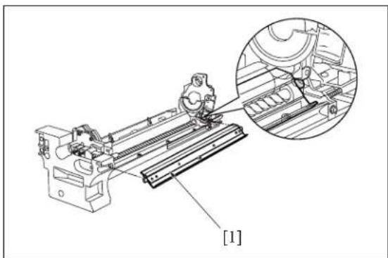
natural_image
Technical line drawing of a mechanical assembly with an inset magnified view (no text or symbols)- Reinstall the above parts following the removal steps in reverse.
Note:
- When installing the cleaning blade [1], install so that the unit's transparent sheet [2] is oriented as shown in the diagram.
- Before installing the drum and cleaning blade (regardless of whether new or used), be sure to coat these with setting powder. Apply the powder around the entire drum, and on both sides of the blade.
- If you have coated setting powder onto the drum: Before installing the drum unit rear into the main body, use an drum cleaner cloth to remove stray powder from the sensor surface on the TCSB (Toner control sensor board). This is necessary to ensure that accurate toner density readings are obtained.

text_image
[2] [1]8. PAPER FEED UNIT
8.1 Replacing the Paper Feed Roller and the Feed Roller (Bypass)
A. Periodically replaced parts/cycle
• Paper feed roller: Every 360,000 copies (Once for every 100,000 copies for actual durable count) (7145)
- Paper feed roller: Every 300,000 copies (Once for every 100,000 copies for actual durable count) (7235/7228/7222)
- Feed roller: Every 360,000 copies (Once for every 100,000 copies for actual durable count) (7145)
- Feed roller: Every 300,000 copies (Once for every 100,000 copies for actual durable count) (7235/7228/7222)
B. Procedure
1.Open the bypass tray.
2. Remove the 3 screws [1] and remove the plate [2].

text_image
[1] [2]- Remove the 2 screws [1], then remove the bypass sensor.
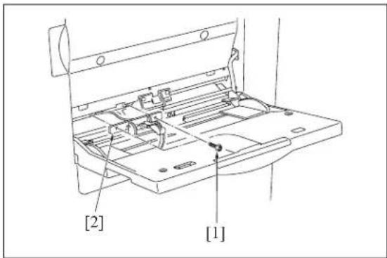
text_image
[2] [1]- Remove the stop ring [1] and the bearing [2].
- Remove the 2 screws [3]. Then slide the bypass feed roller unit [4] to the left side and remove it from the bypass drive shaft [5].
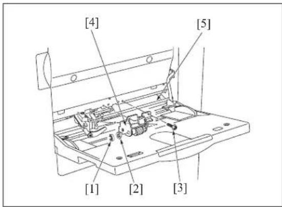
text_image
[4] [5] [1] [2] [3]-
Remove the paper feed roller [1].
-
Remove the 2 stop rings [2].
-
Pull out the bypass conveyance shaft [3], and remove the feed roller [4].
-
Reinstall the above parts following the removal steps in reverse.
Note:
- When reinstalling rollers, pay attention to their orientation.
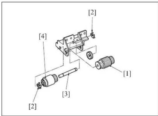
text_image
[2] [4] [3] [2] [1]8.2 Replacing the Double Feed Prevention Roller
A. Periodically replaced parts/cycle
- Double feed prevention roller: Every 360,000 copies (Once for every 100,000 copies for actual durable count) (7145)
- Double feed prevention roller: Every 300,000 copies (Once for every 100,000 copies for actual durable count) (7235/7228/7222)
B. Procedure
- Carry out the steps 1 through to 5 in "8.1 Replacing the paper feed roller and feed roller (bypass)".
- Remove the 2 screws [1], and remove the bypass double feed prevention roller unit [2].
text_image
[2] [1]- Remove the 2 springs [1], the two stop rings [2] and the E ring [3].
- Pull out the shaft [4] to the side where there is no E ring provided, and remove the bypass reverse roller [5] and the roller [6].
- Reinstall the above parts following the removal steps in reverse.

text_image
[2] [4] [6] [5] [1] [1] [3] [2] 7145ma3006Note:
- When reinstalling double feed prevention roller [5], pay attention to their orientation.
8.3 Replacing the Paper Feed Rubber and the Feed Rubber (Tray 1)
A. Periodically replaced parts/cycle
- Paper feed rubber: Every 480,000 copies (Once for every 200,000 copies for actual durable count) (7145)
- Paper feed rubber: Every 400,000 copies (Once for every 200,000 copies for actual durable count) (7235/7228/7222)
- Feed rubber: Every 480,000 copies (Once for every 200,000 copies for actual durable count) (7145)
- Feed rubber: Every 400,000 copies (Once for every 200,000 copies for actual durable count) (7235/7228/7222)
B. Procedure
- Open the ADU door, and then open the conveyance unit.
- Remove the developing unit, the drum unit and the fixing unit.
3.Slide the upper tray 1 [1] out. Remove the 2 screws [2] holding the tray in place, and take the tray 1 [1] off. - Remove the paper feed roller cover [3] in the direction of arrow [2] while pushing it in the direction of arrow [1].
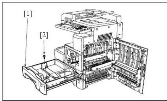
text_image
[1] [2]
text_image
[1] [2] [3]- Remove the 2 stop rings [1] and the bearing [2].
-
Remove the feed shaft [5] from the rocking shaft [4] while raising the shaft on the left side of the paper feed roller unit [3], and remove the paper feed roller unit [3].
-
Remove the collar [1] and pull out the feed shaft [2].
- Remove the feed rubber [4] from the feed roller [3].
- Remove the stop ring [5] and pull out the paper feed shaft [6].
- Remove the paper feed rubber [8] from the paper feed roller [7].
- Reinstall the above parts following the removal steps in reverse.
Note:
- Be sure to install the feed rubber [4] so that the paint mark [9] is turned in the direction as shown in the illustration.
• Install the paper feed roller unit so that the hook of the paper feed roller unit comes above the paper feed roller unit release arm.

text_image
[3] [5] [1] [2] [1] [4]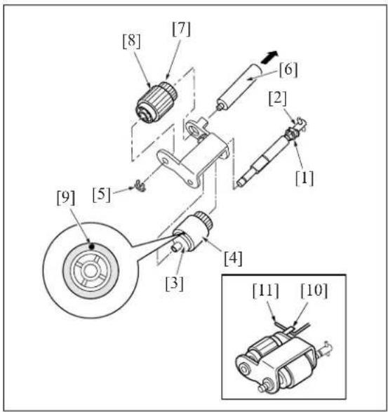
text_image
[8] [7] [6] [2] [1] [9] [5] [4] [3] [11] [10]8.4 Replacing the Double Feed Prevention Rubber (Tray 1)
A. Periodically replaced parts/cycle
- Double feed prevention rubber: Every 480,000 copies (Once for every 200,000 copies for actual durable count) (7145)
- Double feed prevention rubber: Every 400,000 copies (Once for every 200,000 copies for actual durable count) (7235/7228/7222)
B. Procedure
- Open the ADU door.
- Slide the tray 1 [1] out. Remove the 2 screws [2] holding the tray in place, and take the tray 1 [1] off.
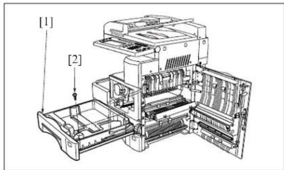
text_image
[1] [2]- Remove the screw [1], and remove the plate [2].
- Remove the screw [3].
- With the claws [4] on both ends sandwiched from the inside of the main body, remove the double feed prevention roller unit [5].
text_image
[1] [2] [3] [4] [5]- Pull out the lever click shaft [1] while pushing the lever section [2] of the lever click shaft [1].
- Remove the double feed prevention rubber [4] from the double feed prevention roller [3].
text_image
[5] [4] [3] [2] [1]- Reinstall the above parts following the removal steps in reverse.
Note:
- Be sure to install the double feed prevention rubber so that the paint mark [5] above is turned in the direction as shown in the illustration.
- When installing the double feed prevention roller unit [1] to the main body, be sure to align the upper section of the claw [2] with the center (the longest scale) of the marking [3] stamped on the main body frame for leveling.
text_image
[1] [3] [2]8.5 Replacing the Paper Feed Rubber and the Feed Rubber (Tray 2)

A. Periodically replaced parts/cycle
- Paper feed rubber: Every 480,000 copies (Once for every 200,000 copies for actual durable count) (7145)
• Paper feed rubber: Every 400,000 copies (Once for every 200,000 copies for actual durable count) (7235/7228/7222) - Feed rubber: Every 480,000 copies (Once for every 200,000 copies for actual durable count) (7145)
- Feed rubber: Every 400,000 copies (Once for every 200,000 copies for actual durable count) (7235/7228/7222)
B. Procedure
- Open the ADU door.
- Remove the screw [1], and remove the plate [2].
text_image
[1] [2]- Remove the 2 stop rings [1] and the bearing [2] on this side, and remove the paper feed roller unit [4] by sliding the bearing [3] on the rear side to the rear.

text_image
[4] [3] θ [1] [2] [1]- Remove the collar [1] and pull out the feed shaft [2].
- Remove the feed rubber [4] from the feed roller [3].
- Remove the stop ring [5] and pull out the paper feed shaft [6].
- Remove the paper feed rubber [8] from the paper feed roller [7].
- Reinstall the above parts following the removal steps in reverse.
Note:
- Be sure to install the feed rubber [4] so that the paint mark [9] is turned in the direction as shown in the illustration.
• Install the paper feed roller unit so that the hook of the paper feed roller unit comes above the paper feed roller unit release arm.
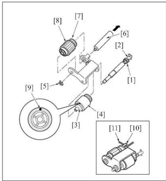
text_image
[8] [7] [6] [2] [1] [9] [5] [4] [3] [11] [10]
text_image
[4] [3] θ [1] [2] [1]
text_image
[8] [7] [6] [2] [1] [9] [5] [4] [3] [11] [10]8.6 Replacing the Double Feed Prevention Rubber (Tray 2)

A. Periodically replaced parts/cycle
- Double feed prevention rubber: Every 480,000 copies (Once for every 200,000 copies for actual durable count) (7145)
- Double feed prevention rubber: Every 400,000 copies (Once for every 200,000 copies for actual durable count) (7235/7228/7222)
B. Procedure
- Open the ADU door.
- Slide the tray 2 [1] out. Remove the 2 screws [2] holding the tray in place, and take the tray 2 [1] off.
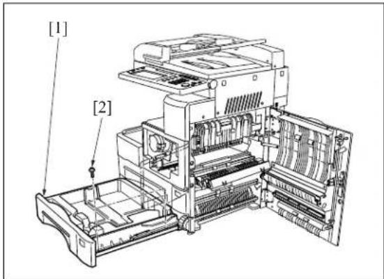
text_image
[1] [2]- Open the guide plate [1], and remove the set screw [2].
- With the claws [3] on both ends sandwiched from the inside of the main body, remove the double feed prevention roller unit [4].
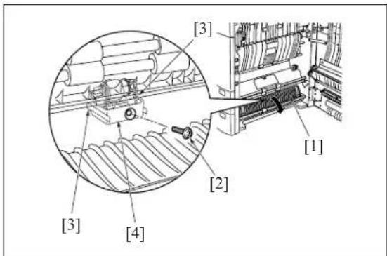
text_image
[3] [2] [1] [3] [4]- While pressing on the lever [2] on the lever click shaft [1], pull out the lever click shaft [1].
- Remove the double feed prevention rubber [4] from the roller [3].
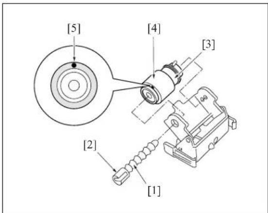
text_image
[5] [4] [3] [2] [1]- Reinstall the above parts following the removal steps in reverse.
Note:
- Be sure to install the double feed prevention rubber so that the paint mark [5] above is turned in the direction as shown in the illustration.
- When installing the double feed prevention roller unit [1] to the main body, be sure to align the upper section of the claw [2] with the center (the longest scale) of the marking [3] stamped on the main body frame for leveling.

text_image
[1] [3] [2]8.7 Cleaning the Paper Dust Removing Brush
- Open the ADU door, and then open the conveyance unit.
- Remove the developing unit and the drum unit.
- Release the catch of the claw [3] while lifting up slightly the lower section on this side [2] of the paper dust removing brush [1], and remove the paper dust removing brush [1] in the arrow-marked direction.
Note:
- Do not bend the metal plate of the paper dust removing brush [1].
- Clean the PET sheet [1] and the plastic part [2] using a cleaning pad and a blower brush.
A. Installation procedure
- Insert the paper dust removing brush [1] from the rear side [2], and confirm that the hole [3] in the brush [1] is engaged with the claw [4].
- Finish installation by reversing the sequence of the removal procedure.

text_image
[1] [3] [2]
text_image
[1] [2]
text_image
[1] [2] [3] [4]9. FIXING UNIT
9.1 Removing and Reinstalling the Fixing Unit
Caution:
- The fixing unit remains extremely hot immediately after power is switched OFF. To avoid injury from burns, do not begin work until the fixing unit has cooled down sufficiently.
- When installing the fixing unit, be sure to firmly tighten the unit's 2 set screws.
A. Procedure
- Open the ADU door [1] and the conveyance unit [2], and loosen the 2 screws [4] holding the fixing unit [3] in place.
- Pull the fixing unit out toward you and remove it.

text_image
[1] [2] [3] [4]Note:
- Do not touch the areas shown in the diagram right when attaching or removing the fixing unit.
-
Observe care, as force applied to the fixing claw and paper exit guide may result in the rollers being scratched.
-
Reinstall the above parts following the removal steps in reverse.
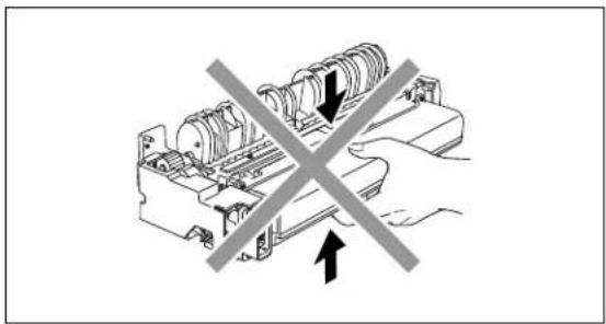
natural_image
Diagram of a mechanical device with a crossed-out X symbol indicating no change or restriction (no text or labels present)9.2 Replacing the Fixing Heater Lamp/1 and Lamp/2
Caution:
- Do not touch the lamp area with bare hands.
A. Periodically replaced parts/cycle
- Fixing heater lamp/1: Every 480,000 copies (7145 only)
- Fixing heater lamp/2: Every 480,000 copies (7145 only)
B. Procedure
- Remove the fixing unit from the main body.
-
Remove the screws [1], and remove the 2 covers/F [2], /R [3].
-
Detach the faston terminal [1] at the rear of each lamp.
Note:
- The marking "B" is stamped on the hole of the lamp support piece for the L3 (Fixing heater lamp /3) [2].
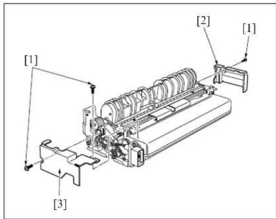
text_image
[1] [2] [1] [3]
text_image
[1] [2]- Detach the faston terminal [1] at the front of each lamp.
- Remove the 2 screws [2], and remove the lamp support piece/F [3].
- Keeping all cord faston terminal wiring straight, pull each fixing heater lamp/1 [4], /2 [5] toward you to remove.
- Reinstall the above parts following the removal steps in reverse.
Note:
- When installing, be sure that manufacturer's mark is mounted on the front side.
- Do not allow the heater lamps to make contact with the inside of the roller.
• Install so that the main lamp is at the top, and the sub lamp is at the bottom.
Heater cords are color-coded as follows.
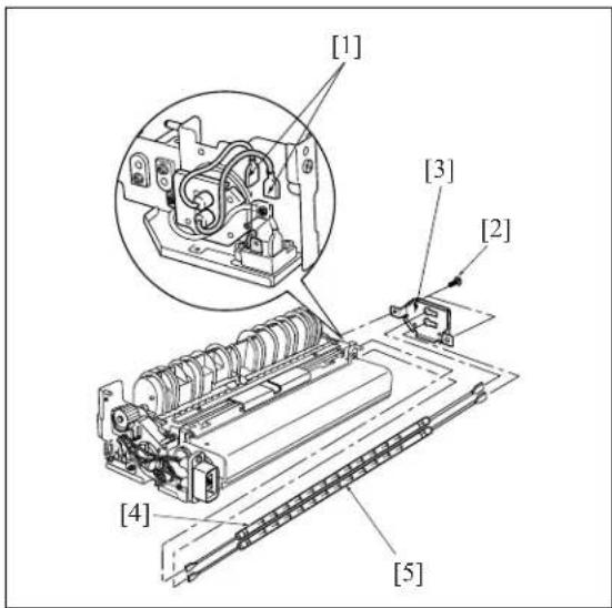
text_image
[1] [3] [2] [4] [5]| Lamp | Color Positions | |||||
| JAPAN U.S.A. | EUROPE OTHERS | |||||
| Front | Rear | Front | Rear | Front | Rear | |
| Main White White Red Red Blue Blue | ||||||
| Sub White Black Red Black Blue Black | ||||||
- When installing the faston terminal on the drive gear side, be sure that the installation position is correct.
9.3 Removing and Reinstalling the Fixing Claw
A. Periodically replaced parts/cycle
• Fixing claw: Every 240,000 copies (7145)
- Fixing claw: Every 200,000 copies (7235/7228/7222)
B. Procedure
- Remove the fixing unit from the main body.
- Remove the 2 covers/F, /R.
3.Open the fixing guide [1]. - Remove the 2 set screws [2], and remove the fixing paper exit board/U [3].
-
Remove the 3 screws [4] from the fixing paper exit board/U, and remove the fixing claw unit [5].
-
Unhook the spring [1] of the fixing claw unit, and remove the fixing claw [2].
- Reinstall the above parts following the removal steps in reverse.
Note:
- When installing the fixing claw, be sure that it is oriented correctly.
- Be sure that the claw is securely attached to the claw spring.
- When installing the fixing paper exit board/U to the fixing unit, be careful not to damage the fixing roller with the fixing claw.
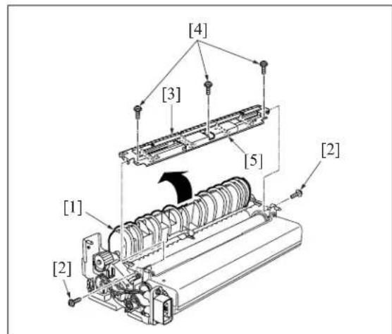
text_image
[4] [3] [5] [2] [1] [2]
text_image
[2] [1]9.4 Replacing the Fixing Web
A. Periodically replaced parts/cycle
- Fixing web (Fixing cleaner assembly) : Every 240,000 copies (7145)
- Fixing web (Fixing cleaner assembly) : Every 200,000 copies (7235/7228/7222)
B. Procedure
- Remove the fixing unit from the main body.
- Remove the front cover and the rear cover of the fixing unit.
- Remove the fixing paper exit board/U.
- Remove the 6 screws [1] and remove the fixing web [2].
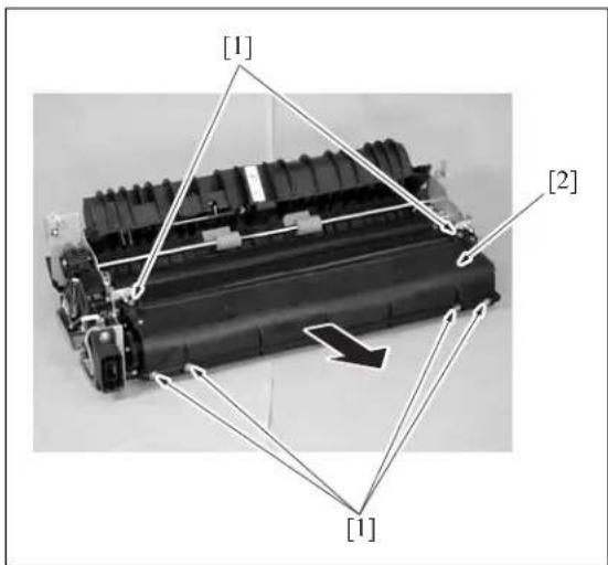
text_image
[1] [2] [1]- Reinstall the above parts following the removal steps in reverse.
Note:
- When replacing the fixing web, be sure to rotate the web drive gear [5] to wind up the edge in blue line [1] of the fixing web until it comes between 0 and 10mm from the nip section [4] of the fixing heating roller [2] and the fixing cleaning roller [3]. On this occasion, be sure to check the web winding shaft [6] if it is also rotating.
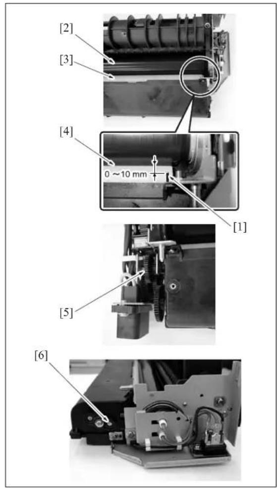
text_image
[2] [3] [4] 0 ~ 10 mm [1] [5] [6]- When installing the fixing claw unit, be careful that the edge of the fixing claw pressing spring [1] does not run on the web case.
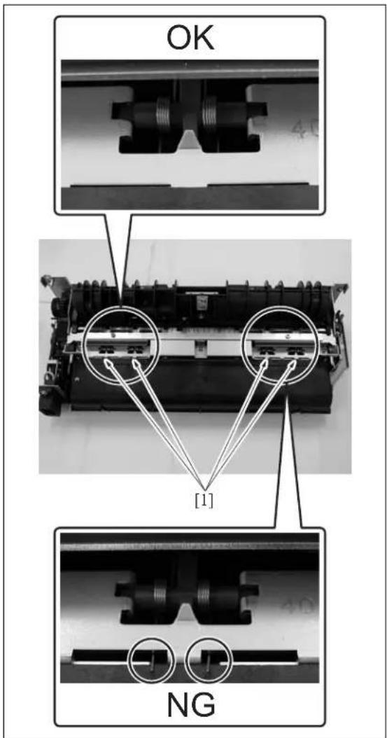
text_image
OK [1] NG9.5 Removing/Reinstalling the Fixing Heat Roller, Fixing Pressure Roller, Heat Insulating Sleeve/A, /B, Fixing Idling gear /B, Fixing Bearing /U, /L, Heater Lamp/1, /2
A. Periodically replaced parts/cycle
- Fixing heat roller: Every 120,000 copies (7145)
- Fixing heat roller: Every 200,000 copies (7235/7228/7222)
- Fixing pressure roller: Every 120,000 copies (7145)
- Fixing pressure roller: Every 200,000 copies (7235/7228/7222)
- Heat insulating sleeve/A: Every 120,000 copies (7145)
- Heat insulating sleeve/A: Every 200,000 copies (7235/7228/7222)
- Heat insulating sleeve/B: Every 120,000 copies (7145)
- Heat insulating sleeve/B: Every 200,000 copies (7235/7228/7222)
- Fixing idling gear/B: Every 120,000 copies (7145)
- Fixing idling gear/B: Every 200,000 copies (7235/7228/7222)
- Fixing bearing /U: Every 240,000 copies (7145)
- Fixing bearing/U: Every 200,000 copies (7235/7228/7222)
• Fixing bearing/L: Every 240,000 copies (7145) - Fixing bearing/L: Every 200,000 copies (7235/7228/7222)
- Fixing heater lamp/1: Every 480,000 copies (7145 only)
- Fixing heater lamp/2: Every 480,000 copies (7145 only)
B. Procedure
- Remove the fixing unit from the main body.
- Remove the fixing claw unit.
- Remove the fixing web.
- Remove the two fixing heater lamps.
- Remove the 2 screws [2] and 2 collars [3] for the connector [1] that was connected to the faston terminal. Remove the connector [1].
- Remove the 2 screws [4], and remove the lamp support piece/R [5].
7.Open the fixing guide [1] to release the pressure.
-
Remove the C-ring [3] at the rear of the heat roller [2], and then remove the gear [4] and heat insulating sleeve/A [5], /B [6].
-
Remove another C-ring [1], then remove the heat insulating sleeve A [2] (the sleeve toward the front).
-
Remove the 2 fixing bearings/U [4] (one at the front, one at the rear) from the fixing unit.
-
Remove the fixing heat roller [3].
Note:
- When the installation, be sure that heat insulating sleeves A and B are oriented and positioned correctly.
When replacing the heating insulating sleeve/A [5], apply solvest 240 [7] to the inside and outside surfaces of the heat insulation sleeve/A [5] and then install it.
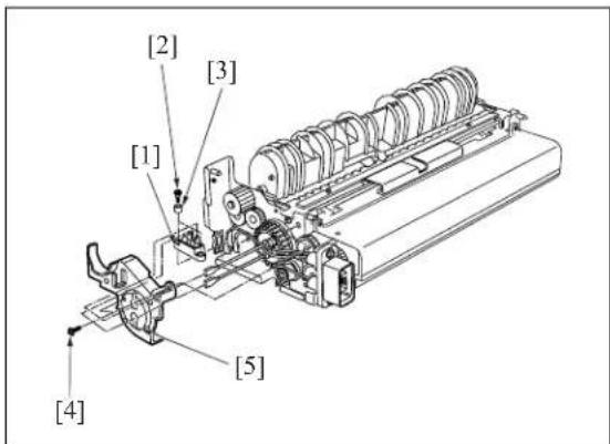
text_image
[2] [3] [1] [4] [5]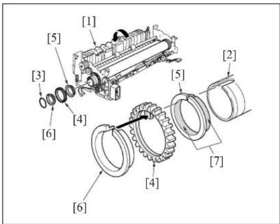
text_image
[1] [5] [3] [4] [6] [5] [2] [7] [4] [6]
text_image
[2] [1] [3] [4]- After removing the fixing pressure roller [1], remove the E-ring at both sides and then remove the 2 fixing bearings/U [2].
- In the case of the 7145 Remove the E-ring, and then remove the fixing idling gear/B [4] and gear [3].
Note:
- When replacing the fixing idling gear/B [4], clean the gear shaft with a drum cleaner.
In the case of the 7235/7228/7222
Remove a screw [1] and then remove the shaft fixing plate caulking [2].
Remove the fixing idling gear/B [3] from the shaft section of shaft fixing plate caulking [2].
Note:
- When replacing the fixing idling gear/B [3] with a new one, clean the shaft section of the shaft fixing plate caulking [2] with drum cleaner.
- Reinstall the above parts following the removal steps in reverse.
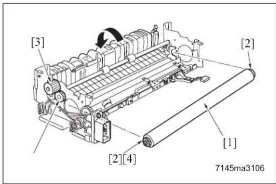
text_image
[3] [2] [1] [2][4] 7145ma3106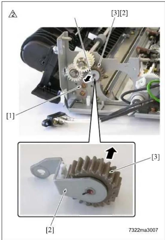
text_image
[1] [3][2] [3] [2] 7322ma3007Note:
- When returning the fixing web in use, be sure to rotate the web drive gear [2] until the original web winding shaft [1] starts to turn.

text_image
[1] [2]- When returning the wiring harness, be sure to hook the wiring harness securely on the wiring harness holder section [1] so that it does not interfere with the web operation lever [2].
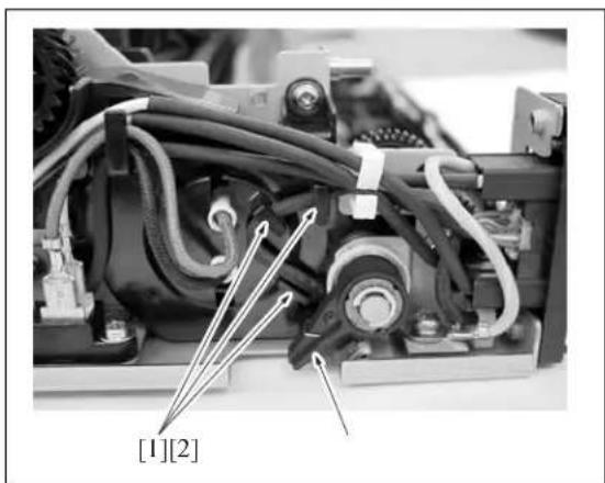
text_image
[1][2]- When installing the fixing claw unit, be careful that the edge of the fixing claw pressing spring [1] does not run on the web case.
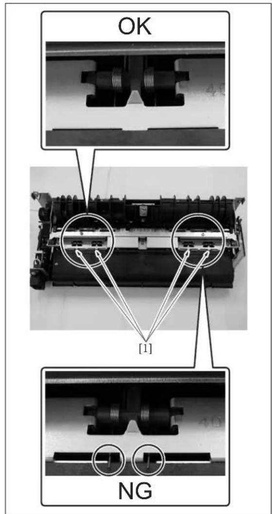
text_image
OK [1] NG9.6 Removing and Reinstalling the Fixing Temperature Sensors
Caution:
• After installing the fixing temperature sensors:
Make sure that the wire bundles are not in contact with the fixing heat roller.
• Make sure that the sensors themselves (the sensor areas) are in contact with the fixing heat roller.
A. Periodically replaced parts/cycle
- Fixing sensor assembly: Every 480,000 copies (7145)
- Fixing sensor assembly: Every 400,000 copies (7235/7228/7222)
B. Procedure
- Remove the fixing unit from the main body.
- Remove the fixing claw unit.
- Remove the fixing web.
- Remove the connector [1].
- Remove the 3 screws [2], and remove the fixing web mounting piece [3].
- Remove the 2 screws [4], and remove the fixing sensor assembly [5].
- Reinstall the above parts following the removal steps in reverse.
Note:
- The fixing sensor assembly [7] is made up of the TH1 (fixing temperature sensor/1) and the TH2 (fixing temperature sensor/2). Since the TH1 and the TH2 have been adjusted at the time of their assembling, avoid surely loosening the screws.
• Make sure that the sensors are in contact with the heat roller.

text_image
[4] [5] [6] [4] [1] [2] [3] [7]- When returning the fixing web in use, be sure to rotate the web drive gear until the original web winding shaft [1] starts to turn.

natural_image
Close-up of an electronic device with visible wiring and components, labeled [1] (no text or symbols on the device itself)- When installing the fixing claw unit, be careful that the edge of the fixing claw pressing spring [1] does not run on the web case.

text_image
OK [1] NG9.7 Removing and Reinstalling the Fuse Mounting Plate Assembly
Caution:
- This is an important safety part. (P/N:SP00-0110) Be sure to observe the following cautions and steps when removing or reinstalling.
Caution:
• After installing the thermostat:
Make sure that the wire bundle is not in contact with the fixing heat roller.
- Make sure that the thermostat itself is in contact with the fixing heat roller.
A. Periodically replaced parts/cycle
- Fuse mounting plate assembly: Every 480,000 copies (7145)
- Fuse mounting plate assembly: Every 400,000 copies (7235/7228/7222)
B. Procedure
- Remove the fixing unit from the main body.
- Remove the fixing claw unit.
- Remove the fixing web.
- Remove the heat roller.
- Remove the fixing web mounting piece.
- Detach the thermostat [1] 2 Faston terminals [2].
- Remove the 2 screws [3], and remove the Fuse mounting plate assembly [4].
- Reinstall the above parts following the removal steps in reverse.
Note:
- When installing the fuse mounting plate assembly, with the base plate sandwiched between the unit's sheet materials, fasten it with the screw while attaching it to the bottom side.
- When connecting the Faston terminals of the thermostat [1], be careful not to deform the plate spring section. Be careful not to mix up the front with the back of the Faston terminal.
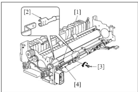
text_image
[2] [1] [3] [4]
- When returning the fixing web in use, be sure to rotate the web drive gear until the original web winding shaft [1] starts to turn after the assembling.

natural_image
Close-up of an electronic device with visible wiring and components, labeled [1] (no text or symbols on the device itself)- When installing the fixing claw unit, be careful that the edge of the fixing claw pressing spring [1] does not run on the web case.
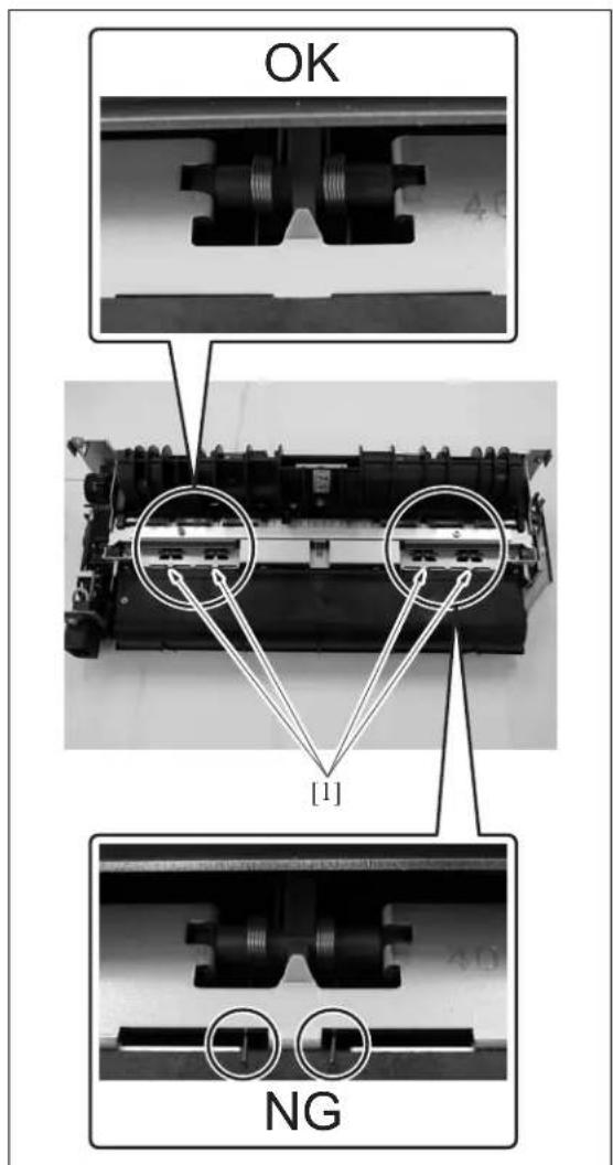
text_image
OK [1] NGBlank page
Konica
SERVICE MANUAL
Models
7145/7222/7228/7235
Service Section
APRIL 2004
KONICA MINOLTA BUSINESS SOLUTIONS U.S.A., INC.
7145/7222/7228/7235
SERVICE MANUAL
APRIL 2004
IMPORTANT NOTICE
Because of the possible hazards to an inexperienced person servicing this equipment, as well as the risk of damage to the equipment, Konica Minolta Business Solutions U.S.A., Inc. strongly recommends that all servicing be performed by Konica Minolta-trained service technicians only.
Changes may have been made to this equipment to improve its performance after this service manual was printed. Accordingly, Konica Minolta Business Solutions U.S.A., Inc., makes no representations or warranties, either expressed or implied, that the information contained in this service manual is complete or accurate. It is understood that the user of this manual must assume all risks or personal injury and/or damage to the equipment while servicing the equipment for which this service manual is intended.
Corporate Publications Department
CONTENTS
SAFETY AND IMPORTANT WARNING ITEMS S-1
IMPORTANT NOTICE S-1
DESCRIPTION ITEMS FOR DANGER, WARNING AND CAUTION S-1
SAFETY WARNINGS S-2
SAFETY INFORMATION S-10
IMPORTANT INFORMATION S-10
SAFETY CIRCUITS S-11
INDICATION OF WARNING ON THE MACHINE S-13
IADJUSTMENT
- HOW TO USE THE ADJUSTMENT SECTION 1-1
1.1 Composition.... 1-1
-
ADJUSTMENTS WHEN REPLACING PARTS 1-1
-
LIST OF ADJUSTMENT ITEMS....1-2
-
CE PASSWORD SETTING 1-4
-
MODE CHANGE MENU 1-4
5.1 Setting method 1-4
- CHECKING BY THE COUNTER KEY FUNCTION 1-5
6.1 Checking method of the counter key function 1-5
- 25 MODE 1-6
7.1 Setting method 1-8
7.2 Setting software DIPSW 1-8
7.3 PM count setting 1-30
7.3.1 PM count reset.... 1-30
7.3.2 Entering PM count start date 1-30
7.3.3 Setting of PM cycle 1-30
7.3.4 Counter clear 1-30
7.4 Data collection.... 1-31
7.5 Copy count for each part to be replaced 1-37
7.5.1 Copy count by parts to be replaced (fixed).... 1-37
7.5.2 Copy count by parts to be replaced (Named; arbitrarily) 1-39
7.6 Password setting 1-41
7.7 Setting phone number of the service center 1-42
7.8 Setting the serial number/the destination 1-42
7.8.1 Setting the serial number 1-42
7.8.2 Setting the destination 1-43
7.9 Displaying the ROM version 1-43
7.10 KRDS setting.... 1-43
7.11 ISW setting 1-43
7.12 Root counter display 1-43
7.13 Setting date 1-44
7.14 Tray size setting 1-44
- 36 MODE 1-45
8.1 Setting method.... 1-45
8.2 Process adjustment 1-45
8.3 L detection adjustment....1-46
8.4 Toner density adjustment....1-46
8.5 Dot diameter adjustment 1-47
8.6 LD1 offset adjustment 1-47
8.7 LD2 offset adjustment (7145 only) 1-48
8.8 Timing adjustment 1-49
8.8.1 Vertical/Horizontal magnification adjustment 1-49
8.8.2 Restart timing adjustment.... 1-52
8.8.3 Paper feed loop amount adjustment....1-54
8.8.4 Leading edge original erasure adjustment 1-55
8.8.5 Centering adjustment 1-56
8.8.6 Image read point adjustment 1-58
8.8.7 Recall standard data....1-59
8.9 Running test mode....1-59
8.9.1 Setting method 1-60
8.10 Test pattern output.... 1-60
8.11 Test pattern density adjustment.... 1-65
8.12 Image quality adjustment.... 1-65
8.12.1 RADF scanning density adjustment 1-65
8.12.2 Non-image area erase check 1-66
8.13 List print 1-67
8.14 Counter clear 1-68
8.15 Adjustment of RADF 1-68
8.15.1 Vertical magnification adjustment in RADF system 1-68
8.15.2 Adjustment of restart timing 1-69
8.15.3 Paper feed loop adjustment 1-70
8.15.4 Centering adjustment 1-70
8.15.5 RADF scanning density adjustment 1-71
8.15.6 RADF image read point adjustment 1-71
8.16 FNS adjustment (FS-112 only) 1-71
8.17 FNS adjustment (FS-114 only) 1-72
8.17.1 Fold & Stitch position adjustment (SK-114) 1-72
8.17.2 Fold position adjustment (SK-114) 1-73
8.17.3 Punch position adjustment (PK-114) 1-73
8.17.4 Punch loop adjustment (PK-114) 1-74
- 47 MODE 1-76
9.1 47 mode setting method 1-76
9.2 RADF original size detection 1-77
9.3 Bypass size detection adjustment 1-77
9.4 Action for mounting when reinstalling the HDD 1-77
9.5 Input check list 1-78
9.6 Output check list 1-84
- OTHER ADJUSTMENTS 1-89
10.1 RADF height adjustment 1-89
10.2 RADF distortion adjustment.... 1-90
10.3 RADF original skew adjustment (front side) 1-91
10.4 RADF original skew adjustment (back side) 1-92
10.5 DB-411 paper-centering adjustment 1-94
10.6 DB-411 tray tilt adjustment 1-95
10.7 LT tray tilt adjustment 1-96
10.8 FS-113 Output Check Mode 1-98
10.9 Lengthwise position adjustment of punch hole of FS-113.... 1-103
10.10 Adjustment of FS-113 Solenoids 1-104
10.11FS-113 Timing Belt Tension Adjustment.... 1-105
10.12FS-113 Adjustment of the Elevator Tray Upper Limit Sensor 1-106
10.13 Adjustment of FS-113 Elevator Tray Overload Detection Level 1-107
10.14 Staple Position Adjustment of FS-114.... 1-108
10.15 Adjustment of the Installation Position of the Shutter Drive Gear of FS-114.... 1-109
10.16Punch Hole Deviance Adjustment of FS-114 (PK-114).... 1-110
10.17Fold Angle Adjustment of SK-114 1-111
10.18 Staple Angle Adjustment of SK-114 1-112
IIISW
- DESCRIPTION OF THE ISW 2-1
- SETUP 2-1
- USB ISW....2-5
IIISERVICE
- SERVICE SCHEDULE 3-1
1.1 Service schedule 3-1
1.1.1 7145....3-1
1.1.2 7235 3-2
1.1.3 7228/7222 3-3
1.2 Maintenance items 3-5
1.2.1 7145....3-5
1.2.2 7235/7228/7222 3-6
1.2.3 DF-318/320 3-7
1.2.4 DB-211/411 3-8
1.2.5 LT-203 3-8
1.2.6 FS-112 3-8
1.2.7 FS-113/RU-101 3-9
1.2.8 FS-114 3-9
1.2.9 PK-114 3-9
1.2.10 SK-114 3-10
1.2.11 BK-114 3-10
1.3 Periodic check items 3-11
1.3.1 7145....3-11
1.3.2 7235/7228/7222 3-13
1.3.3 DF-318 3-15
1.3.4 DF-320 3-15
1.3.5 DB-211 3-16
1.3.6 DB-411 3-16
1.3.7 LT-203 3-16
1.3.8 FS-112 3-17
1.4 Replacement parts list 3-18
1.5 Important maintenance parts 3-20
- 1 PM PARTS KIT 3-21
- SERVICE MATERIALS LIST 3-22
- CE TOOLS LIST 3-23
IVDIAGRAMS
- PARTS LAYOUT DRAWING 4-1
1.1 Main body parts layout drawing 4-1
1.2 DF-318/320 parts layout drawing....4-14
1.3 DB-211 parts layout drawing 4-15
1.4 DB-411 parts layout drawing 4-16
1.5 LT-203 parts layout drawing 4-17
1.6 FS-112 parts layout drawing 4-18
1.7 RU-101 parts layout drawing 4-21
1.8 IT-101 parts layout drawing 4-21
- CONNECTOR LAYOUT DRAWING 4-22
2.1 Main body connector layout drawing 4-22
2.2 DF-318/320 connector layout drawing 4-28
2.3 DB-211 connector layout drawing 4-28
2.4 DB-411 connector layout drawing 4-29
2.5 LT-203 connector layout drawing....4-29
2.6 FS-112 connector layout drawing 4-30
2.7 RU-101 connector layout drawing 4-30
- JAM CODE LIST 4-31
- ERROR CODE LIST 4-39
4.1 Error code list.... 4-39
4.2 About abnormal units isolation.... 4-73
4.3 L detection error code list. 4-74
4.4 Network section status indication 4-74
- TIMING CHART 4-75
5.1 7145 timing chart 4-75
5.2 7235/7228/7222 timing chart 4-76
5.3 7145 ADU timing chart....4-77
5.4 7235/7228/7222 ADU timing chart....4-78
5.5 DF-318/DF-320 timing chart 4-79
5.6 DB-211/DB-411 timing chart 4-81
5.7 LT-203 timing chart 4-82
5.8 FS-112 timing chart 4-83
5.9 FS-113 timing chart 4-85
5.10 FS-114 timing chart 4-89
5.11 SK-114 timing chart 4-91
- OVERALL WIRING DIAGRAM 4-93
6.1 DF-318/320 Overall Wiring Diagram 4-93
6.2 DB-211/411 Overall Wiring Diagram 4-94
6.3 LT-203 Overall Wiring Diagram 4-95
6.4 FS-112 Overall Wiring Diagram.... 4-97
6.5 RU-101 Overall Wiring Diagram 4-99
6.6 FS-113 Overall Wiring Diagram.... 4-101
6.7 SK-114 Overall Wiring Diagram 4-103
7. APPENDIX
7.1 7145 Overall Wiring Diagram (1/4) ...... Appendix-1
7.2 7145 Overall Wiring Diagram (2/4) ...... Appendix-2
7.3 7145 Overall Wiring Diagram (3/4) ...... Appendix-3
7.4 7145 Overall Wiring Diagram (4/4) ...... Appendix-4
7.5 7235/7228/7222 Overall Wiring Diagram (1/4) ......Appendix-6
7.6 7235/7228/7222 Overall Wiring Diagram (2/4) ...... Appendix-7
7.7 7235/7228/7222 Overall Wiring Diagram (3/4) ...... Appendix-8
7.8 7235/7228/7222 Overall Wiring Diagram (4/4) ...... Appendix-9
7.9 FS-114 Overall Wiring Diagram....Appendix-11
Blank page
SAFETY AND IMPORTANT WARNING ITEMS
Read carefully the Safety and Important Warning Items described below to understand them before doing service work.
IMPORTANT NOTICE
Because of possible hazards to an inexperienced person servicing this copier as well as the risk of damage to the copier, Konica Minolta Business Technologies, INC. (hereafter called the KMBT) strongly recommends that all servicing be performed only by KMBT-trained service technicians.
Changes may have been made to this copier to improve its performance after this Service Manual was printed. Accordingly, KMBT does not warrant, either explicitly or implicitly, that the information contained in this Service Manual is complete and accurate.
The user of this Service Manual must assume all risks of personal injury and/or damage to the copier while servicing the copier for which this Service Manual is intended.
Therefore, this Service Manual must be carefully read before doing service work both in the course of technical training and even after that, for performing maintenance and control of the copier properly.
Keep this Service Manual also for future service.
DESCRIPTION ITEMS FOR DANGER, WARNING AND CAUTION
In this Service Manual, each of three expressions “⚠️ DANGER”, “⚠️ WARNING”, and “⚠️ CAUTION” is defined as follows together with a symbol mark to be used in a limited meaning.
When servicing the copier, the relevant works (disassembling, reassembling, adjustment, repair, maintenance, etc.) need to be conducted with utmost care.

DANGER :Action having a high possibility of suffering death or serious injury

WARNING :Action having a possibility of suffering death or serious injury

CAUTION :Action having a possibility of suffering a slight wound, medium trouble, and property damage
Symbols used for safety and important warning items are defined as follows:

:Precaution when using the copier.

General precaution Electric hazard High temperature


):Prohibition when using the copier.

General prohibition Do not touch with wet hand Do not disassemble


:Direction when using the copier.

General instruction

Unplug

Ground/Earth
SAFETY WARNINGS
△ [1] MODIFICATIONS NOT AUTHORIZED BY
KONICA MINOLTA BUSINESS TECHNOLOGIES, INC.
Konica Minolta brand copiers are renowned for their high reliability. This reliability is achieved through high-quality design and a solid service network.
Copier design is a highly complicated and delicate process where numerous mechanical, physical, and electrical aspects have to be taken into consideration, with the aim of arriving at proper tolerances and safety factors. For this reason, unauthorized modifications involve a high risk of degradation in performance and safety. Such modifications are therefore strictly prohibited. the points listed below are not exhaustive, but they illustrate the reasoning behind this policy.

DANGER:PROHIBITED ACTIONS
- Using any cables or power cord not specified by KMBT.
- Using any fuse or thermostat not specified by KMBT. Safety will not be assured, leading to a risk of fire and injury.
- Disabling fuse functions or bridging fuse terminals with wire, metal clips, solder or similar object.
- Disabling relay functions (such as wedging paper between relay contacts)
- Disabling safety functions (interlocks, safety circuits, etc.) Safety will not be assured, leading to a risk of fire and injury.
- Making any modification to the copier unless instructed by KMBT
• Using parts not specified by KMBT

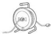


natural_image
Illustration of various electronic components including a transformer, capacitor, and connector (no text or symbols present)


natural_image
Diagram showing two gear heads with a directional arrow indicating rotation (no text or symbols)[2] CHECKPOINTS WHEN PERFORMING ON-SITE SERVICE
Konica Minolta brand copiers are extensively tested before shipping, to ensure that all applicable safety standards are met, in order to protect the customer and customer engineer (hereafter called the CE) from the risk of injury. However, in daily use, any electrical equipment may be subject to parts wear and eventual failure. In order to maintain safety and reliability, the CE must perform regular safety checks.
- Power Supply
![KONICA MINOLTA 7145 - [2] CHECKPOINTS WHEN PERFORMING ON-SITE SERVICE - 1](/content/2026/05/1061009/images/c49319affe8a2f94de433c186ed5c97372af22668d71a869b7cd2dc78be2abf8.jpg)
WARNING: Wall Outlet
- Check that mains voltage is as specified. Plug the power cord into the dedicated wall outlet with a capacity greater than the maximum power consumption.
If excessive current flows in the wall outlet, fire may result. - If two or more power cords can be plugged into the wall outlet, the total load must not exceed the rating of the wall outlet.
If excessive current flows in the wall outlet, fire may result.


text_image
~ kw

WARNING: Power Plug and Cord
- Make sure the power cord is plugged in the wall outlet securely. Contact problems may lead to increased resistance, overheating, and the risk of fire.

- Check whether the power cord is damaged. Check whether the sheath is damaged.
If the power plug, cord, or sheath is damaged, replace with a new power cord (with plugs on both ends) specified by KMBT. Using the damaged power cord may result in fire or electric shock.


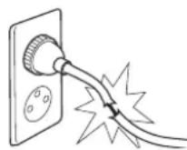
- When using the power cord (inlet type) that came with this copier, be sure to observe the following precautions:
a. Make sure the copier-side power plug is securely inserted in the socket on the rear panel of the copier.
Secure the cord with a fixture properly.
b. If the power cord or sheath is damaged, replace with a new power cord (with plugs on both ends) specified by KMBT.
If the power cord (inlet type) is not connected to the copier securely, a contact problem may lead to increased resistance, overheating, and risk of fire.

natural_image
Line drawing of a hand inserting a cable into a door panel (no text or symbols)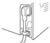
- Check whether the power cord is not stepped on or pinched by a table and so on.
Overheating may occur there, leading to a risk of fire.


WARNING: Power Plug and Cord
- Do not bundle or tie the power cord. Overheating may occur there, leading to a risk of fire.
- Check whether dust is collected around the power plug and wall outlet. Using the power plug and wall outlet without removing dust may result in fire.
- Do not insert the power plug into the wall outlet with a wet hand. The risk of electric shock exists.
- When unplugging the power cord, grasp the plug, not the cable. The cable may be broken, leading to a risk of fire and electric shock.


natural_image
Hand inserting a plug into an electrical socket (no text or symbols visible)


natural_image
Hand holding a screwdriver next to three socket plates (no text or symbols visible)
WARNING: Wiring
- Never use multi-plug adapters to plug multiple power cords in the same outlet. If used, the risk of fire exists.


natural_image
Line drawing of a plug with multiple connectors and wires (no text or symbols)- When an extension cord is required, use a specified one. Current that can flow in the extension cord is limited, so using a too long extension cord may result in fire. Do not use an extension cable reel with the cable taken up. Fire may result.


natural_image
Line drawing of a wire spool with attached cable (no text or symbols)
WARNING: Ground Lead
- Check whether the copier is grounded properly. If current leakage occurs in an ungrounded copier, you may suffer electric shock while operating the copier. Connect the ground lead to one of the following points:


natural_image
Hand connecting a cable to an electrical outlet plug (no text or symbols visible)a. Ground terminal of wall outlet
b. Ground terminal for which Class D work has been done
WARNING: Ground Lead
- Pay attention to the point to which the ground lead is connected.
Connecting the ground lead to an improper point such as the points listed below results in a risk of explosion and electric shock:
a. Gas pipe (A risk of explosion or fire exists.)
b. Lightning rod (A risk of electric shock or fire exists.)
c. Telephone line ground (A risk of electric shock or fire exists in the case of lightning.)
d. Water pipe or faucet (It may include a plastic portion.)


2. Installation Requirements
WARNING: Prohibited Installation Place
- Do not place the copier near flammable materials such as curtains or volatile materials that may catch fire.
A risk of fire exists.
- Do not place the copier in a place exposed to water such as rain water.
A risk of fire and electric shock exists.


natural_image
Line drawing of a kitchen sink with a refrigerator, toilet, and water dispenser (no text or symbols)
WARNING: Nonoperational Handling
- When the copier is not used over an extended period of time (holidays, etc.), switch it off and unplug the power cord.
Dust collected around the power plug and outlet may cause fire.

natural_image
Hand inserting a plug into an electrical socket (no text or symbols visible)CAUTION: Temperature and Humidity
- Do not place the copier in a place exposed to direct sunlight or near a heat source such as a heater.
A risk of degradation in copier performance or deformation exists.
Do not place the copier in a place exposed to cool wind.
Recommended temperature and humidity are as follows:
Temperature: 10^ C to 30^ C
Humidity: 10% to 80% (no dew condensation)
Avoid other environments as much as possible.


natural_image
Illustration of three household appliances: a refrigerator, a portable air conditioner, and a gas stove (no text or symbols present)CAUTION: Ventilation
- Do not place the copier in a place where there is much dust, cigarette smoke, or ammonia gas.
Place the copier in a well ventilated place to prevent machine problems and image faults.

natural_image
Illustration of a portable air conditioner with smoke and bubbles, no text or symbols presentCAUTION: Ventilation
• The copier generates ozone gas during operation, but it is not sufficient to be harmful to the human body.
If a bad smell of ozone is present in the following cases, ventilate the room.
a. When the copier is used in a poorly ventilated room
b. When taking a lot of copies
c. When using multiple copiers at the same time

text_image
Illustration showing a document being discarded into a machine with warning symbols and stacks of waste nearbyCAUTION: Vibration
- When installing the copier, read the Installation Guide thoroughly. Be sure to install the copier in a level and sturdy place.
Constant vibration will cause problems.

text_image
Warning symbol and cartoon illustration of a luggage device with exclamation marks- Be sure to lock the caster stoppers.
In the case of an earthquake and so on, the copier may slide, leading to a injury.
CAUTION: Inspection before Servicing

- Before conducting an inspection, read all relevant documentation (service manual, technical notices, etc.) and proceed with the inspection following the prescribed procedure in safety clothes, using only the prescribed tools. Do not make any adjustment not described in the documentation.
If the prescribed procedure or tool is not used, the copier may break and a risk of injury or fire exists.
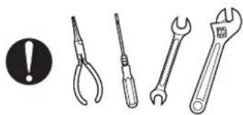
natural_image
Illustration of four different wrenches: a circular warning symbol, five pliers, one wrench, and one adjustable wrench (no text or labels)- Before conducting an inspection, be sure to disconnect the power plugs from the copier and options.
When the power plug is inserted in the wall outlet, some units are still powered even if the POWER switch is turned OFF. A risk of electric shock exists.
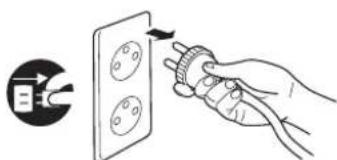
text_image
Diagram showing a hand holding a power plug to switch an electrical outlet, with a battery icon and directional arrow indicating action.• The area around the fixing unit is hot. You may get burnt.
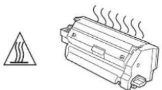
natural_image
Simple line drawing of a heat exchanger with warning symbol (no text or labels)! DANGER: Work Performed with the Copier Powered
• Take every care when making adjustments or performing an operation check with the copier powered.
If you make adjustments or perform an operation check with the external cover detached, you may touch live or high-voltage parts or you may be caught in moving gears or the timing belt, leading to a risk of injury.


DANGER: Work Performed with the Copier Powered
• Take every care when servicing with the external cover detached. High-voltage exists around the drum unit. A risk of electric shock exists.


WARNING: Safety Checkpoints
- Check the exterior and frame for edges, burrs, and other damages. The user or CE may be injured.
- Do not allow any metal parts such as clips, staples, and screws to fall into the copier. They can short internal circuits and cause electric shock or fire.
- Check wiring for squeezing and any other damage. Current can leak, leading to a risk of electric shock or fire.
- When disconnecting connectors, grasp the connector, not the cable. (Specifically, connectors of the AC line and high-voltage parts) Current can leak, leading to a risk of electric shock or fire.
- Carefully remove all toner remnants and dust from electrical parts and electrode units such as a charging corona unit. Current can leak, leading to a risk of copier trouble or fire.
- Check high-voltage cables and sheaths for any damage. Current can leak, leading to a risk of electric shock or fire.
- Check electrode units such as a charging corona unit for deterioration and sign of leakage. Current can leak, leading to a risk of trouble or fire.
- Before disassembling or adjusting the write unit incorporating a laser, make sure that the power cord has been disconnected. The laser light can enter your eye, leading to a risk of loss of eyesight.
- Do not remove the cover of the write unit. Do not supply power with the write unit shifted from the specified mounting position. The laser light can enter your eye, leading to a risk of loss of eyesight.
- When replacing a lithium battery, replace it with a new lithium battery specified in the Parts Guide Manual. Dispose of the used lithium battery using the method specified by local authority. Improper replacement can cause explosion.


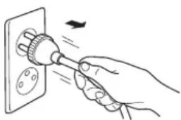
natural_image
Hand using a power tool to switch an electrical outlet (no text or symbols visible)


WARNING: Safety Checkpoints
- After replacing a part to which AC voltage is applied (e.g., optical lamp and fixing lamp), be sure to check the installation state. A risk of fire exists.
- Check the interlock switch and actuator for loosening and check whether the interlock functions properly. If the interlock does not function, you may receive an electric shock or be injured when you insert your hand in the copier (e.g., for clearing paper jam).
- Make sure the wiring cannot come into contact with sharp edges, burrs, or other pointed parts. Current can leak, leading to a risk of electric shock or fire.
- Make sure that all screws, components, wiring, connectors, etc. that were removed for safety check and maintenance have been reinstalled in the original location. (Pay special attention to forgotten connectors, pinched cables, forgotten screws, etc.) A risk of copier trouble, electric shock, and fire exists.

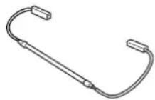


DANGER: HANDLING OF SERVICE MATERIALS
- Toner and developer are not harmful substances, but care must be taken not to breathe excessive amounts or let the substances come into contact with eyes, etc. It may be stimulative. If the substances get in the eye, rinse with plenty of water immediately. When symptoms are noticeable, consult a physician.
- Never throw the used cartridge and toner into fire. You may be burned due to dust explosion.


DANGER : HANDLING OF SERVICE MATERIALS
- Unplug the power cord from the wall outlet. Drum cleaner (isopropyl alcohol) and roller cleaner (acetone-based) are highly flammable and must be handled with care. A risk of fire exists.


natural_image
Hand holding a screwdriver next to a wall-mounted socket (no text or symbols visible)- Do not replace the cover or turn the copier ON before any solvent remnants on the cleaned parts have fully evaporated. A risk of fire exists.

- Use only a small amount of cleaner at a time and take care not to spill any liquid. If this happens, immediately wipe it off. A risk of fire exists.

- When using any solvent, ventilate the room well. Breathing large quantities of organic solvents can lead to discomfort.

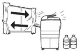
natural_image
Illustration of a portable device emitting air from a stack of bottles, with no visible text or symbols.[3] MEASURES TO TAKE IN CASE OF AN ACCIDENT
![KONICA MINOLTA 7145 - [3] MEASURES TO TAKE IN CASE OF AN ACCIDENT - 1](/content/2026/05/1061009/images/9844bb91b742d3feb13b5d58e9b3ee5745ba64d8128d5a5c20fe8b6da78d0281.jpg)
- If an accident has occurred, the distributor who has been notified first must immediately take emergency measures to provide relief to affected persons and to prevent further damage.
- If a report of a serious accident has been received from a customer, an on-site evaluation must be carried out quickly and KMBT must be notified.
- To determine the cause of the accident, conditions and materials must be recorded through direct on-site checks, in accordance with instructions issued by KMBT.
- For reports and measures concerning serious accidents, follow the regulations given in "Serious Accident Report/Follow-up Procedures".
[4] CONCLUSION
- Safety of users and customer engineers depends highly on accurate maintenance and administration. Therefore, safety can be maintained by the appropriate daily service work conducted by the customer engineer.
- When performing service, each copier on the site must be tested for safety. The customer engineer must verify the safety of parts and ensure appropriate management of the equipment.
SAFETY INFORMATION
IMPORTANT INFORMATION
The Center for Devices and Radiological Health (CDRH) of the U.S. Food and Drug Administration implemented regulations for laser products manufactured since August 1, 1976. Compliance is mandatory for products marketed in the United States.
This copier is certified as a "Class 1" laser product under the U.S.
Department of Health and Human Services (DHHS) Radiation Performance Standard according to the Radiation Control for Health and Safety Act of 1968. Since radiation emitted inside this copier is completely confined within protective housings and external covers, the laser beam cannot escape during any phase of normal user operation.
SAFETY CIRCUITS
This machine is provided with the following safety circuits to prevent machine faults from resulting in serious accidents.
[1] Overall protection circuit
[2] L2 and L3 (fixing heater lamp/1, /2) overheating prevention circuit
These safety circuits are described below to provide the service engineer with a renewed awareness of them in order to prevent servicing errors that may impair their functions.
[1] Overall protection circuit

text_image
CBR1 CBR2 DCPS- Protection by CBR1 and CBR2 (circuit breaker/1, /2)
CBR1 and CBR2 interrupt the AC line instantaneously when an excessive current flows due to a short in the AC line.
CAUTION:
The CBR1 and CBR2 functions must not be deactivated under any circumstances.
[2] L2 and L3 (fixing heater lamp/1, /2) overheating prevention circuit
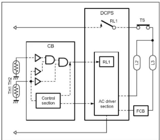
flowchart
graph TD
    A["TH1 TH2"] --> B["Control section"]
    B --> C["CB"]
    C --> D["AC driver section"]
    D --> E["DCPS"]
    E --> F["RL1"]
    F --> G["TS"]
    G --> H["L2"]
    G --> I["L3"]
    H --> J["FCB"]
    I --> J
    J --> K["RL1"]
    K --> L["DCPS"]
    style A fill:#f9f,stroke:#333
    style B fill:#ccf,stroke:#333
    style C fill:#cfc,stroke:#333
    style D fill:#fcc,stroke:#333
    style E fill:#cff,stroke:#333
    style F fill:#ffc,stroke:#333
    style G fill:#cfc,stroke:#333
    style H fill:#fcc,stroke:#333
    style I fill:#cfc,stroke:#333
    style J fill:#fcc,stroke:#333
    style K fill:#cfc,stroke:#333
    style L fill:#fcc,stroke:#333
- Protection by software
The output voltage from TH1, TH2 (fixing temperature sensor/1, /2) is read by the CPU. If this voltage is abnormal, L2 (fixing heater lamp/1), L3 (fixing heater lamp/2) and RL1 (main relay) are turned OFF.
CAUTION:
The RL1 function must not be deactivated under any circumstances.
2. Protection by the hardware circuit
The output voltages from TH1, TH2 (fixing temperature sensor/1, /2) are compared with the abnormality judgment reference value in the comparator circuit. If the output voltage from TH1 or TH2 exceeds the reference value, L2 (fixing heater lamp/1), L3 (fixing heater lamp/2) and RL1 (main relay) are turned OFF in hardware means.
CAUTION:
Periodically check the TH1, TH2 face contacting the roller, and replace TH2 if any abnormality is detected.
The RL1 function must not be deactivated under any circumstances.
3. Protection by TS (thermostat)
When the fixing heat roller exceeds the specified value, TSs (thermostats) are turned OFF, thus interrupting the power to L2 (fixing heater lamp/1), and L3 (fixing heater lamp/2) directly.

CAUTION:
Do not use any other electrical conductor in place of TS1 and TS2.
INDICATION OF WARNING ON THE MACHINE
Caution labels shown below are attached in some areas on/in the machine.
When accessing these areas for maintenance, repair, or adjustment, special care should be taken to avoid burns and electric shock.
③ [1] Main body
1. Right side
<7145>

text_image
CAUTION The fixing unit is very hot. To avoid getting burned DO NOT TOUCH. CAUTION This area generates high voltage. If touched, electrical shock may occur. DO NOT TOUCH! CAUTION (Inside of the main body front door) (Inside of the main body right side door) CAUTION The roller shaft on the inside of the cover is very hot. To avoid getting burned DO NOT TOUCH. If the cover comes off, return it to its original position.CAUTION
You may be burned or injured if you touch any area that you are advised by any caution label to keep yourself away from.
Do not remove caution labels. If any caution label has come off or soiled and therefore the caution cannot be read, contact our Service Office.

<7235/7228/7222>
| CAUTION | High temperature! |
| PRECAUCION | Temperatura alta! |
| 注意 | 高温! |
| 위험 | 고열! |
| Liberiaة مالاً |
| CAUTION | High temperature! |
| VORSICHT | Heisse Oberfläche! |
| ATTENTION | Température élevée! |
| PRECAUCION | ¡Temperatura alta! |
| ATTENZIONE | Alta temperatura! |
| CAUTION | High temperature! |
| ATTENTION | Température élevée! |
| PRECAUCION | ¡Temperatura alta! |
| 注意 | 高温! |
You may be burned or injured if you touch any area that you are advised by any caution label to keep yourself away from.
Do not remove caution labels. If any caution label has come off or soiled and therefore the caution cannot be read, contact our Service Office.

2. Front side

<7145>

You may be burned or injured if you touch any area that you are advised by any caution label to keep yourself away from.
Do not remove caution labels. If any caution label has come off or soiled and therefore the caution cannot be read, contact our Service Office.

<7235/7228/7222>
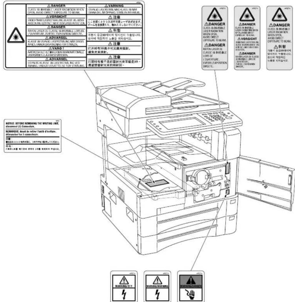
You may be burned or injured if you touch any area that you are advised by any caution label to keep yourself away from.
Do not remove caution labels. If any caution label has come off or soiled and therefore the caution cannot be read, contact our Service Office.


3. Rear/Left side (7235/7228/7222 only)

text_image
警告 WARNING ADVERTÉNCIA 警告 경고 パネルを外す時は、電源プラグを抜いてください。 Unplug the machine before removing panels. Desconecle a unidade da tomada antes de remover os painéis. 在取下后面板之前,请拔出电源插头。 전원를 제거하기전에 기기의 전원 불러그를 돌아구십시오. WARNING DANGER ADVERTÉNCIA 警告 Unplug the machine before removing panels. Débrancher l'appareil avant de retirer les panneaux arrières. Desenchute la máquina antes de quitar los paneles. 在取下背蓋板之前,请拔出電源插頭。 WARNING ADVERTÉNCIA 警告 Unplug the machine before removing panels. Desenchute la máquina antes de quitar los paneles. 在取下后面板之前,请拔出电源插头。 전원를 제거하기전에 기기의 전원 불러그를 돌아구십시오. 경고 السب م Priaz طانه الAIL تيل إزaine اللOutcome الخن DY322sf005e
CAUTION
You may be burned or injured if you touch any area that you are advised by any caution label to keep yourself away from.
Do not remove caution labels. If any caution label has come off or soiled and therefore the caution cannot be read, contact our Service Office.
4. Scanner section
3 <7145>
natural_image
Technical line drawing of a mechanical device with internal compartments and control panels (no text or symbols)7322sf006
CAUTION
You may be burned or injured if you touch any area that you are advised by any caution label to keep yourself away from.
Do not remove caution labels. If any caution label has come off or soiled and therefore the caution cannot be read, contact our Service Office.

<7235/7228/7222>

text_image
Screenshot of an industrial machine with warning icons and labels indicating 'WARNING/WARNING' and 'WARNING/2.2'| 警告 | 原稿ガラスを取り外す時は、電源プラグを抜いてください。 |
| WARNING | Unplug the machine before removing platen glass. |
| ADVERTÊNCIA | Desconecte a unidade da tomada antes de remover o vidro de exposição. |
| 警告 | 在取下稿台玻璃之前,请拔出电源插头。 |
| 경고 | 원고유리판을 제거하기전에 기기의 전원코드를 훔아주십시오. |
| WARNING | Unplug the machine before removing piaten glass. | |
| DANGER | Débrancher le copieur avant de retirer la vitre d'exposition. | |
| ADVERTENCIA | Desenchufe la máquina antes de quitar el vidrio. | |
| 警告 | 在取下原稿台玻璃之前,請拔出電源插頭。 |
| ⚠ WARNING | Unplug the machine before removing platen glass. | |
| ⚠ ADVERTENCIA | Desenchufe la máquina antes de quitar el vidrio. | |
| ⚠警告 | 在取下稿台玻璃之前,请拔出电源插头。 | |
| ⚠경고 | 원고유리판을 제거하기전에 기기의 전원코드를 훈아주십시오. | |
| ### | ### | |
7322sf007e

CAUTION
You may be burned or injured if you touch any area that you are advised by any caution label to keep yourself away from.
Do not remove caution labels. If any caution label has come off or soiled and therefore the caution cannot be read, contact our Service Office.
③ [2] FS-113
![KONICA MINOLTA 7145 - ③ [2] FS-113 - 1](/content/2026/05/1061009/images/8f5ef803602603669f94e982f0116bedbfd1388651a2b69a9fc62e196b366b0c.jpg)
text_image
CAUTION This area is very hot. To avoid getting burned DO NOT TOUCH. (Inside of the Finisher) CAUTION CAUTION ATTENTION ATTENTION VORUSIGHT PRECAUTION PRECAUTION CUDADO FS-113 Finisher 7322sf009③ [3] FS-114
![KONICA MINOLTA 7145 - ③ [3] FS-114 - 1](/content/2026/05/1061009/images/bc567681680ac19b6f9d1c3fa389b1730c005318dedd04f65f7597e5ca1a7152.jpg)
text_image
FS-114 Finisher 注意 CAUTION VORSICHT ATTENTION PRECAUCIÓN 7322sf010CAUTION
You may be burned or injured if you touch any area that you are advised by any caution label to keep yourself away from.
Do not remove caution labels. If any caution label has come off or soiled and therefore the caution cannot be read, contact our Service Office.
I A D J U S
1. HOW TO USE THE ADJUSTMENT SECTION
1.1 Composition
This section details adjusting items and procedures.
A. Checking before starting work
Use this section for making adjustments and as a checklist before implementing corrective measures in the field.
- Does the power supply meet the requirements?
- Is the power supply properly grounded?
- Is the machine sharing its power source with another high current consumption machine that draws large currents intermittently? (e.g. an elevator, air conditioner, or other source of electrical consumption)
-
Is the installation environment suitable?
-
The machine must be installed in a wellventilated place free from high temperature, high humidity and direct sunlight.
-
The machine must be installed on a level floor.
-
Does the cause of a defective image lie in the original itself?
-
Is the density adjusting control at the proper position?
-
Are the platen glass and the slit glass clean?
- Is the correct paper being used for the copy?
- Are the copying materials and parts replaced when they reach the end of their usable life? (developer, drum, cleaning blade, etc.)
- Is there toner in the toner bottle?
T B. Checkpoints when conducting on-site service
Be sure to pay due attention to the following when repairing the machine.
- Only one side of the AC power line is disconnected when the main power of this machine is turned off. Always unplug the machine before beginning work. If absolutely necessary to work with the power on, exercise care to avoid being caught in the scanning rear of the exposure unit.
- Special care should be taken when handling the fixing unit since it operates at extremely high temperatures.
- The developing unit is surrounded by a strong magnetic field. Keep watches and metering equipment away from it.
- Avoid scarring the drum with tools or similar objects.
- Do not touch IC pins with your bare hands.
2. ADJUSTMENTS WHEN REPLACING PARTS
Adjustments (including checks) and settings are not only required when a defective copy image occurs, but also after replacing or reinstalling certain parts.
[How to use the tables]
The following items are used in the tables throughout this section.
- Mode
Indicates the adjustment mode.
"25": 25 mode
"36": 36 mode
"47": 47 mode
2. Symbols used in the tables
①, ②..... : Indicates there is a pri-
ority sequence for
adjustments (including
checks) and settings.
○ (Empty circle) : Indicates adjustments
(including checks) and
settings that can be car-
ried out independently.
- LIST OF ADJUSTMENT ITEMS
3
| Adjustment classification Adjustment | items | Mode | Page | Drum | Developer | Fixing unit-related parts | Write unit | Parameter memory board | Paper feeding-related rubber rollers | RADF | RADF slit glass | E-RDH | ||
| 1 | PM counter resetting | 25 1-30 O O | 1 | |||||||||||
| 2 | PM cycle set 25 1-30 | O | ||||||||||||
| 3 | Process adjustment | L detection adjustment 36 1-46 | 1*1 | O | *2 | |||||||||
| 4 | Process adjustment | Toner density adjustment 36 1-46 O | 2 | 1 | ||||||||||
| 5 | Process adjustment | Dot diameter adjustment 36 1-47 O | 3 | 2 | ||||||||||
| 6 | Process adjustment | LD1 offset adjustment 36 1-47 O | 2 | 4 | 3 | |||||||||
| 7 | Process adjustment | LD2 offset adjustment (7145) 36 | 1-48 O | 3 | 5 | 4 | ||||||||
| 8 | Image adjustment | Magnification adjustment | Vertical magnifi-cation of printer | 36 1-49 | O | O | O | |||||||
| 9 | Image adjustment | Magnification adjustment | Vertical magnifi-cation of scan-ner (platen) | 36 1-51 | O | O | O | |||||||
| 10 | Image adjustment | Magnification adjustment | Vertical magnifi-cation of scan-ner (RADF) | 36 1-52 | O | O | O | O | ||||||
| 11 | Image adjustment | Magnification adjustment | Horizontal mag-nification of scanner | 36 1-51 | O | O | ||||||||
| 12 | Image adjustment | Timing adjust-ment | Main body related | 36 1-52 | O | O | O | |||||||
| 13 | Image adjustment | Timing adjust-ment | RADF | 36 1-53 | O | O | O | O | ||||||
| 14 | Image adjustment | Timing adjust-ment | Paper feed loop amount adjust-ment | 36 1-54 O | ||||||||||
| 15 | Image adjustment | Timing adjust-ment | Leading edge original erasure adjustment | 36 1-55 | O | O | ||||||||
3
| Adjustment classification | Adjustment items | Mode | Page | Drum | Developer | Fixing unit-related parts | Write unit | Parameter memory board | Paper feeding-related rubber rollers | RADF | RADF slit glass | E-RDH | ||
| 16 | Image adjustment Timing adjustment | Image read point adjustment | 36 1-58 ○ | ○ | ||||||||||
| 17 | Image adjustment Centering adjustment | Main body related Centering adjustment | 36 1-56 ○ | ○ | ||||||||||
| 18 | Image adjustment Centering adjustment | DBLT centering adjustment | 36 1-56 ○ | ○ | ||||||||||
| 19 | Image adjustment Centering adjustment | RADF centering adjustment | 36 1-58 ○ | ○ | ○ | |||||||||
| 20 | Image adjustment RADF adjustment | RADF scanner density adjustment | 36 1-65 ○ | ○ | ○ | |||||||||
| 21 | Drum count resetting | Drum count resetting 25/36 | 1-40 ○ | |||||||||||
| 22 | Fixing unit related counter resetting | Fixing unit related counter resetting | 25/36 1-68 | ○ | ||||||||||
| 23 | E-RDH memory check | E-RDH memory check | 47 1-88 | ○ | ||||||||||
*1 After replacing the developer, be sure that you do not make any copies until you have first carried out L detection adjustment.
*2 When PRMB (Parameter memory board) is replaced, remember to replaced the developer before conducting the L deection adjustment.
Note:
- When replacing a board due to the SCB (System control board) being damaged, the PRMB (Parameter memory board) that was installed on the damaged SCB should be used as a rule on the new SCB.
The use of a new PRMB should be limited only when it is considered that the PRMB is also damaged.
On this occasion, adjustment data have not been input into the new PRMB and it is necessary to implement all of the adjustment items. In order to make the new PRMB effective, the 47 mode - 92 (output) should be carried out before implementation of the adjustment items.
- When the adjustment items have been implemented, the 47 mode - 96 (output) should be also executed. The adjustment data are backed up by implementing the 47-96 mode.
For the original PRMB installed on the damaged SCB, the 47-92 mode is protected against inadvertent execution. For details of the cancellation of protection, contact the service manager of the authorized distributor.
4. CE PASSWORD SETTING
Important:
- In order to prevent the malicious CE to access data and to change settings of the machine, ensure to change the CE password.
On key operator mode, if the enhanced security is enabled, CE password must be input to verify the CE to access the following service modes.
"36 mode"
"25 mode"
"47 mode"
Register a CE password by the following procedure.
A. Procedure
- While the SW1 (main power switch) is ON, turn OFF SW2 (sub power switch)
- Turn the SW2 ON while pressing 2 and 5 of the copy quantity setting buttons
CE password input request screen appears.
3.Enter default password "92729272". On the LCD, basic screen for 25 mode appears. - Press [5. Password setting] key. Password setup screen appears.
- Press [4. CE Password setting] key.
CE password input screen appears.
6.Enter new 8-digit CE password then press [Set] key.
7.OFF/ON sub-switch to complete password input procedure and to exit from 25 mode.
Note:
- Only alphanumerical keys can be used for the password. Continuous single alphanumeric cannot be used for the password.
- In order to change the registered password, in the above step 3, enter current password and continue following steps.
Do not use name, your birthday or employee code number as the password since other people can easily guess them.
2 • CE should not inform other people of the password.
5. MODE CHANGE MENU
5.1 Setting Method
The following modes can be selected on the mode change menu screen without turning OFF/ON the power supply:
"1 Basic screen"
"2 36 mode"
"3 25 mode"
"4 Key operation mode"
"5 47 mode"
"6 Exit"
A. Procedure
- Turn on SW1 (main power switch) and SW2 (sub power switch).
- Keep pressing the * button until the message "Enter password for mode selection" appears.
3.Input 9272 as the password and press the [START] key. (The password is fixed and cannot be changed.) - Press the key of the mode to be selected on the screen.
If enhanced security is enabled, enter CE password to access to "25 mode", "36 mode" and "47 mode". Enter Key operator password to access [Key operator mode].
- To return to the "Mode Change Menu screen", keep pressing the * button until the "Mode Change Menu screen" appears.
- When the adjustment ends, press [6. Exit] key and the basic screen will appear.
6. CHECKING BY THE COUNTER KEY FUNCTION
The counter key function enables to display of the following parameters by using the counter button:
"1 Total count"
"2 Total count start date"
"3 PM count/PM count limit"
"4 PM count start date"
"5 Fax send paper count"
"6 Fax receive paper count"
"7 Printer count"
"8 Scanner count"
"9 Drum count"
"10 Developing count"
"11 Fixing unit count"
6.1 Checking Method of the Counter Key Function
A. Procedure
- Turn on SW1 (main power switch) and SW2 (sub power switch).
- Press the counter button.
- The "Counter confirmation screen" appears, and the total count value appears. The counter that appears differs depending upon the installed option.
- If you press the ! button on the "Counter confirmation screen", service-related counters that indicate the PM count, and so on, appear.
- To output the count value list, press the [PRINT] key.
- Press the [OK] key or the stop button to return to the basic screen.
7.25 MODE
| Adjustment item menu Remarks | |||
| 1. Software DIPSW setting | See the “List of soft-ware DIPSW”. | ||
| 2. PM COUNT/CYCLE | 1. PM COUNT reset | ||
| 2. PM CYCLE set | |||
| 3. Counter clear 1. Drum | related counter | ||
| 3. Counter clear 2. Fixing | related counter | ||
| 3. Collecting data 1. Count data collection | Data Collection 1 Copy count of each paper size RADF paper passage count | ||
| 1. Count data collection | Data Collection 2 JAM occurrence count by each point | ||
| 1. Count data collection | Data Collection 3 Copy count of each mode | ||
| 1. Count data collection | Data Collection 4 SC count : F code | ||
| 2. Periodic data collection starts | |||
| 4. Parts counter 1. Count of parts (Fixed) | |||
| 5. Password setting 1. Key operator password setting 8 digits | |||
| 6. Service TEL No. setting | Telephone & Fax. No. of service center setting. | ||
3
| Adjustment item menu Remarks | ||
| 7. Serial number setting | 1. Main body Sets up the serial | number display and the destination. |
| 2. Optional tray | ||
| 3. LCT | ||
| 4. Finisher | ||
| 5. Fax | ||
| 6. Printer | ||
| 7. FL-102/FL-103 | ||
| 8. FS-114 punch unit | ||
| 9. FS-114 saddle unit | ||
| 10.RADF (7235/7228/7222) | ||
| 8. Indication of ROM version | Display each version of ROM. | |
| 9. KRDS setting See the | KRDS man- | ual provided separately. |
| 10. ISW Rewrites the con- | tents of the flash ROM of each board. | |
| 11. Indication of Root counter | Displays the root coun-ter (total counter). | |
| 12. Setting date Sets the | starting date | of the total counter. |
| 13. Tray size setting Set | the paper size of | LT-203. |
7.1 Setting Method
A special operating mode called "25 Mode" has been provided with this machine. This mode enables rewriting of the non-volatile storage and specify other various settings.
A. Procedure
-
Turn OFF the SW2 (sub power switch) when the SW1 (main power switch) remains ON.
-
Turn the SW2 ON while pressing 2 and 5 of the copy quantity setting buttons.
If enhanced security is enabled, CE password input request screen appears. Input the CE password.
25 mode menu screen appears. At this moment, the machine turns to 25 mode and the normal copy operation is disabled. - Press the desired item key on the LCD screen. Each setting screen will appear.
4.Enter data in each selected screen. - Press the [RETURN] key to check the data that has been entered.
- Turn the SW2 off to cancel the 25 mode.
- New data will be effective after restarting.
7.2 Setting Software DIPSW
A. Setting method
This setting specifies the software DIPSW on the software SW setting screen.
Note:
- The bit of the DIP switch is written in the non-volatile memory every time it is changed.
B. Meaning of the values displayed on the screen
text_image
Pheny netting and Software SW Software SW 01 - 0 : ] 01 ON OFF RETURN [1][2][3][4][1]DIPSW number
[2]Bit number (0 to 7)
[3]Bit data : 1:ON, 0:OFF
[4]8-bit switch values in indicated in hexadecimals from 00 to FF.
C. Procedure
- Enter the 25 Mode.
2."25 mode menu screen"
Press the [Software SW] key.
- "Software setting screen"
Select DIP switch number.
Use the arrow key on the left.
- Select bit number of the DIP switch.
Use the arrow key at the center.
- Select ON (=1) or OFF (=0) of the DIP switch.
Use [ON] or [OFF] key.
[ON]: Set bit.
[OFF]: Clear bit.
- Press the [RETURN] key to return to the "25 mode menu screen".
- For each switch function, see "List of software DIPSW".
List of software DIP SW
Note:
- Be sure not to change bits with no particular reference made of the function.

| DIPSW No. | Bit Functions 0 1 Default values | ||||||
| Japan | Inch Metric | ||||||
| DIPSW1 0 | Operation when key counter is removed | Ignore Instantaneous stop Jam | 0 | 1 | 1 | ||
| 1 A | 3 (11 x 17) counting method | Count as 1 Count as 2 0 0 0 | |||||
| 2 | — | — | — | ||||
| 3 S | Selection of maximum number of copies that can be sta-pled by FS-112/113 | *1 | *1 | 0 | 0 | 0 | |
| 4 | 0 | 0 | 0 | ||||
| 5 | — | — | — | ||||
| 6 | — | — | — | ||||
| 7 F | S-112/114 limit on number of stapled sets | None | * | 0 | 0 | 0 | |
| DIPSW2 0 | Toner | replenish stop timing 1 Decide with DIPSW 3-2 | Stop after paper exited | 0 | 0 | 0 | |
| 1 | — | — | — | ||||
| 2 | — | — | — | ||||
| 3 | — | — | — | ||||
| 4 | — | — | — | ||||
| 5 | 1-shot message display at automatic staple mode clearing | Yes | No | 1 | 1 | 1 | |
| 6 | — | — | — | ||||
| 7 P | Prohibition of non-image area erases, repeat (auto) and original position correction | No | Yes | 0 0 0 | |||
| DIPSW3 0 | Use F | 4 size for Latin Amer-ica destination | No | Yes | 0 0 0 | ||
| 1 | SC latch (F34/F35/F36) | Unlatched | Latched | 0 | 0 | 0 | |
| 2 Toner replenish stop timing 2 When copying ends | Interval between copy set | 0 | 0 | 0 | |||

* FS-112: Message is displayed after stopping temporarily at 25 copies.
FS-114: Message is displayed after stopping temporarily at 20 copies.

| DIPSW No. | Bit | Functions | 0 | 1 | Default values | ||
| Japan | Inch | Metric | |||||
| DIPSW3 3 | Return to EKC screen after copying reservation | No Yes 0 | 0 0 | ||||
| 4 | — | — | — | ||||
| 5 | — | — | — | ||||
| 6 | — | — | — | ||||
| 7 | — | — | — | ||||
| DIPSW4 0 | Toner level detection ("Supply toner" indication) | *2 | *2 | 0 | 0 | 0 | |
| 1 | 0 | 0 | 0 | ||||
| 2 | Condition for stopping copy-ing after toner supply display | *3 | *3 | 1 | 1 | 1 | |
| 3 | 1 | 1 | 1 | ||||
| 4 | Non-display of advance/delete buttons for job list | Yes No 0 | 0 0 | ||||
| 5 | Job stop when there is no toner left. | No Yes 1 | 1 1 | ||||
| 6 | Copy reservation allowed (cor-responding to coin vendor) | Can reserve copying | Cannot reverse copying | 0 | 0 | 0 | |
| 7 | — | — | — | ||||
| DIPSW5 | 0 | — | — | — | 0 | 1 | 0 |
| 1 | — | — | — | ||||
| 2 | — | — | — | ||||
| 3 | — | — | — | ||||
| 4 | — | — | — | ||||
| 5 | Toner consumption reduction SW | *5 | *5 | 0 | 0 | 0 | |
| 6 | 0 | 0 | 0 | ||||
| 7 | — | — | — | ||||
| DIPSW6 | 0 | — | — | — | 0 | 0 | 0 |
| 1 K | size selection SW for Tai-wan destination | Metric sizes | K sizes available | 0 | 0 | 0 | |
| 2 | K size selection SW for Taiwan destination (By pass feed) | Metric sizes | K sizes available | 0 | 0 | 0 | |
| 3 | — | — | — | ||||
| DIPSW6 4 | Timing for the polygon motor to stop/start to rotate at low speed | *6 | *6 | 0 | 0 | 0 | |
| 5 | 1 | 1 | 1 | ||||
| 6 Setting for the polygon motor to stop/rotate at low speed | *7 *7 | 1 | 1 | 1 | |||
| 7 | 0 | 0 | 0 | ||||
| DIPSW7 0 | Selection of automatic erasure outside original | *8 | *8 | 1 | 1 | 1 | |
| 1 Automatic restart after feeding paper (Other than Inch) | *9 | *9 | 0 | 0 | 0 | ||
| 2 Automatic conversion of paper size detected by APS (8.5 x 11/A4) | *10 | *10 1 0 0 | |||||
| 3 Nonstandard-size notification for platen APS A4 (Japan, Metric)/8.5x11 (Inch) | *11 | *11 0 0 0 | |||||
| 4 Nonstandard-size notification for platen APS B6 (Japan)/A5 (Metric)/5.5 x 8.5 (Inch) | *11 | *11 0 0 0 | |||||
| 5 Password that requires 25/36/47 mode (9272) | Not required Required 0 0 0 | ||||||
| 6 Selection of A series size (Metric only) | No Yes 0 0 0 | ||||||
| 7 | — | — | — | 0 | 0 | 0 | |
| DIPSW8 0 | — | — — | 1 0 0 | ||||
| 1 Changing of key operator fixed magnification setting | Permit | Prohibit | 1 0 0 | ||||
| 2 Disabling copying when PM count reached | Permit | Prohibit | 0 0 0 | ||||
| 3 | — | — | — | 0 | 0 | 0 | |
| 4 Priority tray when APS is released | *12 | *12 0 0 0 | |||||
| 5 | 0 | 0 | 0 | ||||
| 6 | 0 | 0 | 0 | ||||
| 7 For checking the collected data 2 to 4 in the 25 mode | Display restricted | Display not restricted | 0 | 0 | 0 | ||
| DIPSW9 0 | Selection of copy quantity limit | *13 | *13 0 0 0 | ||||
| 1 | 0 | 0 | 0 | ||||
| 2 | 0 | 0 | 0 | ||||
| 3 | 0 | 0 | 0 | ||||
| 4 | — | — | — | ||||
| 5 | — | — | — | ||||
| 6 Switching of message | *14 | *14 0 0 0 | |||||
| 7 | 0 | 0 | 0 | ||||
| DIPSW10 0 | Setting for summer time | *15 | *15 0 0 0 | ||||
| 1 | 1 | 1 | 1 | ||||
| 2 | 1 | 1 | 1 | ||||
| 3 | 0 | 0 | 0 | ||||
| 4 Selection of magnification mode when APS function is cancelled | Display auto 1.00 0 0 0 | ||||||
| 5 | — | — | — | ||||
| 6 Icon display in the LCD message display section (toner shortage, PM) | No Yes 1 0 0 | ||||||
| 7 Displaying of JAM code | No Yes 0 0 0 | ||||||
| DIPSW11 | 0 Release of the applied function when the RADF is open | No Yes 0 0 0 | |||||
| 1 | — | — | — | ||||
| 2 | — | — | — | ||||
| 3 | — | — | — | ||||
| 4 | — | — | — | ||||
| 5 | — | — | — | ||||
| 6 | — | — | — | ||||
| 7 | — | — | — | ||||
| DIPSW12 0 | — — | — 0 0 0 | |||||
| 1 | — | — | — | ||||
| 2 | — | — | — | ||||
| 3 Setting of PM count at which copying is inhibited | *16 | *16 0 0 0 | |||||
| 4 | 0 | 0 | 0 | ||||
| 5 | 0 | 0 | 0 | ||||
| 6 KRDS connection recognition | Not recognize Recognize 0 0 0 | ||||||
| 7 | F/E code screen switchover (except for F34, F35 and F36) | No | Switched (all in F code) | 0 | 0 | 0 | |
| DIPSW13 0 | — — | — 0 0 0 | |||||
| 1 | — | — | — | ||||
| 2 | — | — | — | ||||
| 3 Selection of filter for jagged edges on slanting lines | ON | OFF | 0 0 0 | ||||
| 4 | — | — | — | ||||
| 5 | — | — | — | ||||
| 6 Judging level of the out-of-original auto erasure mode | *17 | *17 1 1 1 | |||||
| 7 | 0 | 0 | 0 | ||||
| DIPSW14 0 | Operation when stapling is not possible (Other than B6R, post card nonstandard)* | *18 | *18 0 1 0 | ||||
| 1 | 0 | 1 | 0 | ||||
| 2 | — | — | — | ||||
| 3 | — | — | — | ||||
| 4 Operation when one position stapling is not available* | *19 | *19 0 0 0 | |||||
| 5 | 0 | 0 | 0 | ||||
| 6 Operation when two position stapling is not available* | *20 | *20 0 0 0 | |||||
| 7 | 0 | 0 | 0 | ||||
* Common to FS-112/113
| DIPSW No. | Bit | Functions | 0 | 1 | Default values | ||
| Japan | Inch | Metric | |||||
| DIPSW15 0 | — — | — 0 0 0 | |||||
| 1 | — | — | — | ||||
| 2 | — | — | — | ||||
| 3 | — | — | — | ||||
| 4 | — | — | — | ||||
| 5 | — | — | — | ||||
| 6 | Stopping due to overloading when the FNS is not connected (when exiting 100 sheets) | Not stop Stop 0 0 0 | |||||
| 7 | Stopping due to overloading when the FNS, IT is not connected (when exiting 400 sheets) | Decided on DIPSW15-6 | Stop 1 1 1 | ||||
| DIPSW16 0 | Fixing temperature at low power mode | *21 | *21 0 1 1 | ||||
| 1 | *a | 0 | 0 | ||||
| 2 | Operation of internal heater | Always ON Heater off while in off mode | 1 | 1 | 1 | ||
| 3 | Copying before execution of the L detection | Permit | Prohibit | 1 1 1 | |||
| 4 | — | — | — | ||||
| 5 | — | — | — | ||||
| 6 | Control of dot diameter adjustment | *22 | *22 1 1 1 | ||||
| 7 | *b | *b | *b | ||||
| DIPSW17 0 | F4 s | ze setting | *23 | *23 0 0 0 | |||
| 1 | 0 | 0 | 0 | ||||
| 2 | 0 | 0 | 0 | ||||
| 3 | HOST printing cannot be performed when a key counter is installed | Printing takes place | Printer abort processing | 0 | 0 | 0 | |
| 4 | — | — | — | ||||
| 5 | Shift from bypass feed in ATS mode is inhibited | Shift inhibited | Shift possible | 0 0 0 | |||
| 6 | — | — | — | ||||
^* a Default value of the 7145 is "0". Default value of the 7235/7228/7222 is "1".
*b Default value of the 7145 is "0". Default value of the 7235/7228/7222 is "1".
3
| DIPSW No. | Bit Functions 0 | 1 Default values | |||||
| Japan | Inch | Metric | |||||
| DIPSW17 7 | Separation claw operationOFF mode (for machinesdestined for China) | Normal OFF | 0 0 0 | ||||
| DIPSW18 0 | Tray 1 (main body upperstage), separation of defec-tive part | Normal Not allowed to use | 0 | 0 | 0 | ||
| 1 Tray 2 (main body lowerstage), separation of defec-tive part | Normal Not allowed to use | 0 | 0 | 0 | |||
| 2 — | — | — | |||||
| 3 — | — | — | |||||
| 4 Tray 3 (DB upper stage),separation of defective part | Normal Not allowed to use | 0 | 0 | 0 | |||
| 5 Tray 4 (DB lower stage),separation of defective part | Normal Not allowed to use | 0 | 0 | 0 | |||
| 6 Tray 5 (LT), separation ofdefective part | Normal Not allowed to use | 0 | 0 | 0 | |||
| 7 DB is isolated Normal Not allowed to | use | 0 | 0 | 0 | |||
| DIPSW19 0 | Separation of defective partof printer controller | Normal Not allowed to use | 0 | 0 | 0 | ||
| 1 Separation of defective partof FAX board | Normal Not allowed to use | 0 | 0 | 0 | |||
| 2 — | — | — | |||||
| 3 Separation of defective partof HDD | Normal Not allowed to use | 0 | 0 | 0 | |||
| 4 Separation of defective partof ADU | Normal Not allowed to use | 0 | 0 | 0 | |||
| 5 Separation of defective partof scanner | Normal Not allowed to use | 0 | 0 | 0 | |||
| 6 — | — | — | |||||
| 7 Separation of defective partof RADF | Normal Not allowed to use | 0 | 0 | 0 | |||
| DIPSW No. | Bit | Functions | 0 | 1 | Default values | ||
| Japan | Inch | Metric | |||||
| DIPSW20 0 | Separation of defective part of Network | Normal Not allowed to use | 0 | 0 | 0 | ||
| 1 Separation of defective part of IEEE1284 | Normal Not allowed to use | 0 | 0 | 0 | |||
| 2 Separation of defective part of USB | Normal Not allowed to use | 0 | 0 | 0 | |||
| 3 | — | — | — | ||||
| 4 Separation of defective part of FNS | Normal Not allowed to use (Offset not allowed to use)* | 0 | 0 | 0 | |||
| 5 Separation of defective part of the saddle | Normal Not allowed to use | 0 | 0 | 0 | |||
| 6 | — | — | — | ||||
| 7 | — | — | — | ||||
| DIPSW21 0 | Platen size recognition selector switch 1 for Latin America (Inch only) | 8.5 x 11 A4 0 0 0 | |||||
| 1 Platen size recognition selector switch 2 for Latin America (Inch only) | 8.5 x 11R A4 R 0 0 0 | ||||||
| 2 Platen size recognition selector switch 3 for Latin America (Inch only) | 8.5 x 14 F4 0 0 0 | ||||||
| 3 Notice of nonstandard small platen size (Inch only) | Notice of noticed size | Notice as non-standard size | 0 | 0 | 0 | ||
| 4 Job suspension/end at pulling out key counter | *24 | *24 0 0 0 | |||||
| 5 Notice of small size of platen mode (8.5x11/A4 or smaller) | Notice size detected by APS | Notice size as A4 (Japan, Metric) or 8.5x11 (Inch) | 0 | 1 | 0 | ||
| 6 Switching of the count-up function | *25 | *25 0 0 0 | |||||
| 7 When using an EKC, the password screen appears at the end of each job | No Yes 0 | 0 0 | |||||
* The saddle is also detached.
| DIPSW No. | Bit | Functions | 0 | 1 | Default values | ||
| Japan | Inch | Metric | |||||
| DIPSW22 0 | — — | — 1 1 1 | |||||
| 1 Nonstandard size becomes effective at automatic platen start | *26 | *26 0 0 0 | |||||
| 2 | — | — | — | 0 | |||
| 3 | — | — | — | 0 | |||
| 4 Indication of total count start day on counter key mode screen | No Yes 0 0 0 | ||||||
| 5 | — | — | — | 0 | |||
| 6 | — | — | — | 0 | |||
| 7 | — | — | — | 1 | |||
| DIPSW23 0 | Automatic changeover to Tray 1 when FNS tray is full* | No Yes 1 1 1 | |||||
| 1 Automatic changeover to Tray 2 when FNS tray is full* | No Yes 1 1 1 | ||||||
| 2 Automatic changeover to Tray 3 when FNS tray is full* | No Yes 1 1 1 | ||||||
| 3 Automatic changeover to Tray 4 when FNS tray is full* | No Yes 1 1 1 | ||||||
| 4 100 sheets are exited when FNS is not stapled, and tray is detected full* | No Yes 0 0 0 | ||||||
| 5 100 sheets are exited when FNS is stapled, and tray is detected full* | No Yes 1 1 1 | ||||||
| 6 | — | — | — | 0 | |||
| 7 Machine stops when fixing web count reaches to the limit | No Yes 0 0 0 | ||||||

* FS-112 only (7145)

| DIPSW No. | Bit | Functions | 0 | 1 | Default values | ||
| Japan | Inch | Metric | |||||
| DIPSW24 0 | — — | — 0 0 0 | |||||
| 1 | — | — | — | ||||
| 2 A | Automatic change of printer paper size | *27 *27 0 | 0 0 | ||||
| 3 | 0 | 0 | 0 | ||||
| 4 | — | — | — | ||||
| 5 | — | — | — | ||||
| 6 P | Punching of mixed size print job | Release punch automatically | Not release punch and continue | 0 | 0 | 0 | |
| 7 Job stop changeover without print process stop | *29 | *29 0 0 0 | |||||
| DIPSW25 0 | Automatic changeover to tray 1 when the IT tray is full | No Yes | 0 0 0 | ||||
| 1 A | Automatic changeover to tray 2 when the IT tray is full | No Yes | 0 0 0 | ||||
| 2 | — | — | — | ||||
| 3 | Switching of TSL control | Normal on/off | All off | 0 | 0 | 0 | |
| 4 | — | — | — | ||||
| 5 F | For postcard-to-postcard copying, rotation takes place even when APS/AMS is not used | No Yes | 0 0 0 | ||||
| 6 180 degree rotation takes place even when there are no staples | No Yes | 0 0 0 | |||||
| 7 F | AX transmission 8K/16K for machines destined for Taiwan | Image is transmitted in reduced form | Image is transmitted with both edges erased | 0 | 0 | 0 | |
| DIPSW26 0 | — — | — 0 0 0 | |||||
| 1 | — | — | — | ||||
| 2 | — | — | — | ||||
| 3 | Image position reference use for bypass feed copying on non-standard size paper | Center | Rear side of transfer paper | 0 | 0 | 0 | |
| 4 P | Printer EKC mismatch print operation | Permit | Prohibit | 0 0 | 0 | ||
| 5 | — | — | — | ||||

| DIPSW No. | Bit | Functions | 0 | 1 | Default values | ||
| Japan | Inch | Metric | |||||
| DIPSW26 6 | The timer for canceling a job that was interrupted due to removal of the key counter is valid | Disabled Enabled 0 0 0 | |||||
| 7 Scanner function Yes No 0 0 0 | |||||||
| DIPSW27 0 | Automatic copying reservation function | *30 *30 0 0 0 | |||||
| 1 Paper exit function with face up in the double sided copy mode (corresponding to letter head paper) | Not provided Provided 0 0 0 | ||||||
| 2 Permission SW for copying double sided special paper | Permit Prohibit 0 0 0 | ||||||
| 3 | — | — | — | 0 | 0 | 0 | |
| 4 Image rotation control when using scanner | Only those smaller than A4/letter rotate | Those larger than A4/letter also rotate | 0 | 0 | 0 | ||
| 5 Density setting when the printer toner save function is selected | *31 | *31 0 0 0 | |||||
| 6 | 0 | 0 | 0 | ||||
| 7 | 0 | 0 | 0 | ||||
| DIPSW28 0 | Leading edge position adjustment at image rotation | *37 | *37 0 0 0 | ||||
| 1 | 0 | 0 | 0 | ||||
| 2 | 0 | 0 | 0 | ||||
| 3 | 0 | 0 | 0 | ||||
| 4 Image leading edge adjustment in platen memory copy | *38 | *38 0 0 0 | |||||
| 5 | 0 | 0 | 0 | ||||
| 6 | 0 | 0 | 0 | ||||
| 7 | 0 | 0 | 0 | ||||
| DIPSW29 0 | Selection of the transfer/separation output of user paper (tray) | *32 | *32 0 0 0 | ||||
| 1 | 0 | 0 | 0 | ||||
| 2 | 1 | 1 | 1 | ||||
| 3 T SL control of user paper (tray) | *33 | *33 0 0 0 | |||||
| 4 | 0 | 0 | 0 | ||||
| 5 | — | — | — | 0 | 0 | 0 | |
| 6 | — | — | — | 1 | 1 | 1 | |
| DIPSW29 7 | Operation of the rear separation claw while in single-side printing | Not provided | Provided 0 0 0 | ||||
| DIPSW30 0 | Selection of the transfer/separation output of user paper (by-pass) | *34 | *34 0 0 0 | ||||
| 1 | 0 | 0 | 0 | ||||
| 2 | 0 | 0 | 0 | ||||
| 3 TSL control of user paper (by-pass) | *35 | *35 0 0 0 | |||||
| 4 | 0 | 0 | 0 | ||||
| 5 | — | — | — | ||||
| 6 | — | — | — | ||||
| 7 | — | — | — | ||||
| DIPSW31 0 | Automatic power on by RADF operation during the power save mode | *36 | *36 1 1 1 | ||||
| 1 Use of E-mail Permit Prohibit 0 0 0 | 0 | ||||||
| 2 Use of scan to FTP Permit Prohibit 0 0 0 | 0 | ||||||
| 3 Use of BOX | Permit Prohibit | 0 0 0 | |||||
| 4 | — | — | — | ||||
| 5 | — | — | — | ||||
| 6 SMB function setting | No function provided | Function provided | 1 | 1 | 1 | ||
| 7 8.5 x 14 is detected for F4 size | F4 | 8.5 x 14 | 0 0 0 | ||||
| DIPSW32 0 | Mode intended for automatic deletion of document | Except files received by PC-Fax | Delete all | 0 0 0 | |||
| 1 Konica Minolta Scan Distributor setting | No function provided | Function provided | 0 | 0 | 0 | ||
| 2 LDAP function setting | No function provided | Function provided | 1 | 1 | 1 | ||
| 3 | — | — | — | ||||
| 4 | TiFF encoding system used when Scan To E-mail is employed | MMR | MH 0 0 0 | ||||
| 5 | — | — | — | ||||
| 6 | — | — | — | ||||
| 7 Job list name switch | file name user name | 0 0 0 | |||||
3
3
3
| DIPSW No. | Bit | Functions | 0 | 1 | Default values | ||
| Japan | Inch | Metric | |||||
| DIPSW33 0 | Number of punch hole | *39 | *39 0 0 0 | ||||
| 1 | 0 | 0 | 0 | ||||
| 2 Notice of the paper feed tray when a coin bender is being used with APS prohibited | Invalid Valid | 0 0 0 | |||||
| 3 Change-over of the display of FAX transmitting address | Invalid Valid | 0 0 0 | |||||
| 4 Change-over of the display of BOX related list password | “*” Displayed | displayed normally | 0 | 0 | 0 | ||
| 5 | — | — | — | 0 | |||
| 6 | KRDS/RDmode change (7145) | KRDS | RDmode | 0 | 0 | 0 | |
| 7 Mixplex function setting | Valid Invalid | 0 0 0 | |||||
| DIPSW34 0 | System OFF setting when the system is shut off or SW2 (sub-power) is turned off | Not set | Set | 0*a | 0*a | 0*a | |
| 1 | FS-114 paper exit tray position | *40 | *40 0 0 0 | ||||
| 2 | 0 | 0 | 0 | ||||
| 3 | 0 | 0 | 0 | ||||
| 4 | Printing starts when paper is provided in the FS-114 saddle | Permit | Prohibit | 0 0 0 | |||
| 5 Correspondence to Open-Print | Not corresponding | Corresponding | 0 0 0 | ||||
| 6 USB Print | Not corresponding | Corresponding | 1 1 1 | ||||
| 7 Overlay void setting (7235/7228/7222 only) | Not set | Set | 0 0 0 | ||||
| DIPSW35 0 | Paper exit to entire A5R finisher tray | Prohibit | Permit | 0 0 0 | |||
| 1 | — | — | — | 0 | |||
| 2 | — | — | — | 0 | |||
| 3 | — | — | — | 0 | |||
| 4 | — | — | — | 0 | |||
| 5 | — | — | — | 0 | |||
| 6 | — | — | — | 0 | |||
| 7 | — | — | — | 0 | |||

^* a In the case of the 7235/7228/7222, default value is "1".
| DIPSW No. | Bit Functions 0 1 Default values | ||||||
| Japan | Inch Metric | ||||||
| DIPSW40 0 | Use of SNMP Permit Prohibit 0 0 0 | ||||||
| 1 | — | — | — | ||||
| 2 | — | — | — | ||||
| 3 | — | — | — | ||||
| 4 | — | — | — | ||||
| 5 | — | — | — | ||||
| 6 | — | — | — | ||||
| 7 | — | — | — | ||||
*1 FS-112 stapling upper limit
| Mode 1-4 1-3 | ||
| 50 sheets 0 0 | ||
| 45 sheets 0 1 | ||
| 40 sheets 1 0 | ||
| 35 sheets 1 1 |
\*2 Toner level detection (toner supply display)
After the TLD (Toner level sensor) detects the no toner condition for more than a specified period of time, this sets a timing for displaying the message "Please supply toner".
| Mode 4-1 4-0 | ||
| 0 effective copies 0 0 | ||
| 100 effective copies 0 1 | ||
| 200 effective copies 1 0 | ||
| 500 effective copies 1 1 |
\*3 Condition for stopping copying after toner supply display
After displaying a message set in DIPSW4-0/-1, the count up to which the copy is prohibited is set.
| Mode 4-3 4-2 | ||
| 100 effective copies 0 0 | ||
| 400 effective copies 0 1 | ||
| 700 effective copies 1 0 | ||
| 1000 effective copies 1 |
\*5 SW for decreased toner consumption
Decreasing the developing bias, charging grid potential by 50V (20 step) in this setting allows the consumption of toner to be reduced. Increasing the potential by 50V (20 step) allows the image density to increase a little.
| Mode 5-6 5-5 | ||
| No adjustment 0 0 | ||
| Toner consumption increased (image density increased) | 0 | 1 |
| Toner consumption decreased (image density decreased ) | 1 | 0 |
| No adjustment 1 1 |
\*6 Timing for the polygon motor to stop/start a low speed rotation
When the setting of the polygon motor is made for stopping or a low speed rotation, the motor is shifted into a low speed rotation or stopping after the elapse of time specified by this DIPSW. The elapsed time starts either at one of the following:
- When the warm-up is completed.
- When the final operation of the operation keys (except the start key)/RADF/tray while in idling.
- When the output of a copy or print job is completed.
| Mode 6-5 6-4 | ||
| 15 seconds 0 0 | ||
| 30 seconds 0 1 | ||
| 60 seconds 1 0 | ||
| 120 seconds 1 1 |


*7 Setting of the polygon motor for stopping or low speed rotation
In order to reduce the sound of rotation of the polygon motor while in idling, it is possible to switch the rotation of the polygon motor either to a low speed rotation or stopping. The timing for the switching is set based on *6 Timing for the polygon motor to stop/start a low speed rotation. When the polygon motor is stopped or rotating at low speed, the time required for the first copy being made is increased.
| Mode 6-7 6-6 | ||
| No preliminary rotation (high speed) | 0 | 0 |
| Preliminary rotation (low speed) | 0 | 1 |
| Stopping 1 0 |
*8 Out-of-original auto erasure
When the AMS has been released due to the original size being not the same as that of the transfer paper size, this setting is used in the platen copy to decide whether the out-of-original area is erased or not. This is the same function as the memory switch function in the key operator mode. (Switching is not available in the RADF copy mode.)
| Mode 7-0 | |
| Out-of-original auto erasure 0 | |
| Out-of-original erasure only while in APS/AMS | 1 |
*9 Automatic re-starting after paper supply (excluding inch system)
| Mode 7-1 | |
| Re-starting by turning on the START button | 0 |
| Re-starting by setting the tray (automatic) | 1 |
*10 Automatic conversion of the APS detected paper size (8.5 x 11/A4)
The paper size detected by the APS is automatically converted according to the standard shown below before being copied.
| Mode 7-2 | |
| No automatic conversion 0 | |
| A4 → 8.5 x 11 (Inch) | 1 |
| 8.5 x 11 → A4 (Japan, Metric) |
*11 Switching of non-standard size notice of platen APSA4 (Japan/Metric), 8.5 x 11 (inch) When the original size is detected as a non-standard size, the switching is made to decide a copying method: a copy is made forcibly into the following size or it is made in the size selected as a non-standard size.
When both the DIPSW 7-3 and 7-4 are 1, the DIPSW7-4 has preference over 7-3.
| Mode 7-3 | |
| Copied in the size selected 0 | |
| Copied forcibly as A4 (Japan, Metric) /8.5 x 11 (Inch) | 1 |
| Mode 7-4 | |
| Copied in the size selected 0 | |
| Copied forcibly as B6 (Japan) /A5 (Metric)/5.5 x 8.5 (Inch) | 1 |
*12 Priority tray when APS is released This setting sets the tray selection used when APS is set OFF from key-operator mode.
| Mode 8-6 8-5 8-4 | |||
| No priority | 0 | 0 | 0 |
| Main-body upper tray | 0 | 0 | 1 |
| Main-body lower tray | 0 | 1 | 0 |
| DB upper tray | 0 | 1 | 1 |
| DB lower tray | 1 | 0 | 0 |
*13 Copy quantity limit
| Mode 9-3 9-2 9-1 9-0 | |||
| No limit 0 0 0 0 | |||
| 1 sheet 0 0 0 1 | |||
| 3 sheets 0 0 1 0 | |||
| 5 sheets 0 0 1 1 | |||
| 9 sheets 0 1 0 0 | |||
| 10 sheets 0 1 0 1 | |||
| 20 sheets 0 1 1 0 | |||
| 30 sheets 0 1 1 1 | |||
| 50 sheets 1 0 0 0 | |||
| 99 sheets 1 0 0 1 |
*14 Switching of message
| Mode 9-7 9-6 | ||
| Please insert key counter | 0 | 0 |
| Please insert copy card 0 1 | ||
| Please insert coin 1 0 |
*15 Summer time setting
| Mode 10-3 10-2 | 10-1 | 10-0 | ||
| 0 minute | 0 0 | 0 0 | ||
| 30 minutes | 0 0 | 1 1 | ||
| 60 minutes | 0 1 | 1 0 | ||
| 90 minutes | 1 0 | 0 1 | ||
| 120 minutes 1 1 0 0 | ||||
| 150 minutes 1 1 1 1 |
*16 Setting of the number of copies until the copying operation is prohibited when PM is attained
If the setting of the copy prohibition when DIPSW8-2 reaches PM is "1", the copying operation is stopped after the following PM count is reached.
| Mode | 12-5 | 12-4 | 12-3 |
| 1000 copies | 0 | 0 | 0 |
| 2000 copies | 0 | 0 | 1 |
| 3000 copies | 0 | 1 | 0 |
| 4000 copies | 0 | 1 | 1 |
| 5000 copies | 1 | 0 | 0 |
*17 Judging level in the out-of-original auto erasure mode
This setting is for the application function of the out-of-original auto erasure mode. When the out-of-original auto erasure is set to "automatic" in the key operator mode, a threshold value is set for detection of the original area.
| Mode | 13-7 | 13-6 |
| Thick original | 0 0 | |
| Normal original | 0 1 | |
| Corresponding to hybrid lights | 1 | 0 |
| — | 1 | 1 |
*18 Operation if stapling is not possible
The positioning of staples is made against the image of an original. Since stapling is restricted only to the front or rear of the leading edge (the main body side of the paper exited) of the transfer paper, or to both of these two positions, stapling may be sometimes unavailable (when stapling is not allowed) depending on the position specified. This SW is used to set the operation when stapling is not allowed.
| Mode | 14-1 | 14-0 |
| Auto cancel | 0 0 | |
| Auto switching to 1-position stapling | 0 | 1 |
| Inhibit | 1 0 | |
| Forced 2-position stapling mode operation | 1 | 1 |
*19 Operation when one position stapling is not available
| Mode | 14-5 | 14-4 |
| Auto cancel | 0 0 | |
| Auto cancel | 0 1 | |
| Inhibit | 1 0 | |
| Forced 1-position sta-pling mode operation | 1 | 1 |
*20 Operation when two position stapling is not available
| Mode 14-7 14-6 | ||
| Auto cancel 0 0 | ||
| Auto cancel 0 1 | ||
| Inhibit 1 0 | ||
| Forced 2-position sta-pling mode operation | 1 | 1 |
*21 Fixing temperature at low power mode Set the fixing temperature while in the low power mode.
③ In the case of the 7145
| Mode 16-1 16-0 | ||
| 155°C 0 0 | ||
| 120°C 0 1 | ||
| 85°C 1 0 | ||
| 85°C 1 1 |
3 In the case of the 7235/7228/7222
| Mode 16-1 16-0 | ||
| 70°C 0 0 | ||
| 120°C 0 1 | ||
| 120°C 1 0 | ||
| 70°C 1 1 |
*22 Dot diameter adjustment control In this setting, the SW is used to change the timing for the dot diameter adjustment.
| Mode 16-7 16-6 | ||
| The power is off for more than 8 hours with humidity over 60% | 0 | 0 |
| The power is off for more than 8 hours (7145) | 0 | 1 |
| At all times (Every time SW2 is turned on) | 1 | 0 |
| Non (7235/7228/7222) | 1 | 1 |
*23 F4 size setting
| Mode 17-2 17-1 | 17-0 | ||
| 8.5 x 13 0 0 0 | |||
| 8.25 x 13 0 0 1 | |||
| 8.125 x 13 0 1 0 | |||
| 8 x 13 0 1 1 | |||
| 8.5 x 13.5 | 1 0 0 |
*24 Job interruption/termination operation when the key counter is being drawn out This is to set the operation of the copier when outputting a print job.
The details of the operation can be changed by the combination of this setting and the DIPSW1:0 setting.
| Mode | 21-4 |
| DIPSW1-0:0 Terminate by stopping paper feed | 0 |
| DIPSW1-0:1 Clear jamming immediately | |
| DIPSW1-0:0 Interrupt by stopping paper feed | 1 |
| DIPSW1-0:1 Clear jamming immediately |
*25 Switching of the count-up function
| Mode | 21-6 |
| Normal operationCounting up for both the total counter and the key counter | 0 |
| While in copying, both the total counter and the key counter count upIn the printer/FAX mode, only the total counter counts up | 1 |
*26 Automatic feed of non-standard size originals in the platen auto start mode
The setting of the automatic selection of auto-start is available for the memory switch setting in the key operator mode. When this setting is in the following condition, a setting can be made to decide if the paper is automatically fed from the bypass tray.
- The setting of the automatic selection of auto-start is on with the original size (platen) detected as non-standard.
| Mode 22-1 | |
| Auto start does not take place 0 | |
| Auto start takes place when the bypass tray is selected | 1 |
*27 Printer paper size automatic conversion
The paper size specified by the print job is automatically changed and output according to the following standard.
| Mode 24-2 24-3 | ||
| No conversion 0 0 | ||
| Inch → Metric 0 1 | ||
| Metric → Inch 1 0 | ||
| Non (not allowed to select) | 1 | 1 |

*29 Switching of the job stop with no process stop The SW is used to decide if a process stop is made at the breaks between continuous two or more jobs reserved.
| Mode 24-7 | |
| No process stop 0 | |
| Process stop 1 |
*30 Automatic copy reservation function
When this setting is "1", the copy reservation screen automatically appears after the end of the original read operation. Also, the job settings are the same as the settings for the previous job.
| Mode 27-0 | |
| Do not use 0 | |
| Use | 1 |
*31 Density setting when the toner save function is selected in the printer driver screen
When "Toner saving mode" is on in the printer driver, the print density is set in the range shown below.
This setting is effective only for the PCL and PS versions.
| Mode | 27-7 | 27-6 | 27-5 |
| Standard | 0 | 0 | 0 |
| -4 (Lighter) | 0 | 0 | 1 |
| -3 | 0 | 1 | 0 |
| -2 | 0 | 1 | 1 |
| -1 | 1 | 0 | 0 |
| +1 | 1 | 0 | 1 |
| +2 | 1 | 1 | 0 |
| +3 (Darker) | 1 | 1 | 1 |
*32 Selection of the transfer/separation output of the user paper (tray)
This SW is used to set the transfer/separation output which is applicable when the specified paper is selected in the "Paper type setting" in the key operator mode.
| Mode | 29-2 | 29-1 | 29-0 |
| Plain paper (Japan) | 0 | 0 | 0 |
| Plain paper (Inch) | 0 | 0 | 1 |
| Plain paper (Metric) | 0 | 1 | 0 |
| Thick paper | 0 | 1 | 1 |
| Thin paper | 1 | 0 | 0 |
| Recycled paper | 1 | 0 | 1 |
*33 TSL control of user paper (tray)
This SW is used to set the TSL control which is applicable when the specified paper is selected in the "Paper type setting" in the key operator mode.
When this SW is used to select the "Switched according to the environment", the switching is made between "Normal control" and "All off" according to the environment.
- "Switched according to the environment" performs the TSL control according to the humidity detected by the main body HUM1 (Humidity sensor).
| Mode 29-4 29-3 | ||
| Normal control 0 0 | ||
| All off 0 1 | ||
| Switched according to the environment | 1 | 0 |
*34 Selection of the transfer/separation output of user paper (bypass feed)
When selecting the bypass tray on the copy basic screen, this SW is used to set the transfer/separation output which is applicable when selecting the user specified paper for "Special paper setting" or the specified paper for "Paper type setting" in the key operator mode.
| Mode 30-2 30-1 | 30-0 | ||
| Plain paper (Japan) 0 0 0 | |||
| Plain paper (Inch) 0 0 1 | |||
| Plain paper (Metric) 0 1 0 | |||
| Thick paper 0 1 1 | |||
| Thin paper | 1 0 0 | ||
| Recycled paper | 1 0 1 |
*35 TSL control of user paper (bypass feed)
When selecting the bypass tray on the copy basic screen, this SW is used to set the TSL control which is applicable when selecting the user paper for "Special paper setting" or the specified paper for "Paper type setting" in the key operator mode.
When this SW is used to select the "Switched according to the environment", the switching is made between "Normal control" and "All off" according to the environment.
- "Switched according to the environment" performs the TSL controle according to the humidity detected by the main body HUM1 (Humidity sensor).
| Mode 30-4 30-3 | ||
| Normal control 0 0 | ||
| All off 0 1 | ||
| Switched according to the environment | 1 | 0 |
*36 Automatic power on by the RADF operation during the power save mode In this setting, when the following operation is made during the power save mode, the power is automatically turned on.
- When the original is set in RADF (when the PS301 (No original sensor) is turned off).
- When the platen/RADF is opened (when PS15 (APS timing sensor) is turned off).
- When the platen/RADF is closed (when PS15 (APS timing sensor) is turned on).
| Mode | 31-0 |
| Disabled | 0 |
| Enabled | 1 |
*37 While rotating image during copying 1-2 mode, leading edge of the 2nd side shifts 3 to 4mm. This dipswitch is to adjust that shift.
| Mode 28-3 28-2 | 28-1 | 28-0 | |||||
| + | 0 | m | m | 0 | 0 | 0 | |
| + | 0 | . | 5 | m | m | 0 | |
| -0.5mm | 1 | 0 | 0 | 1 | |||
| + | 3 | . | 5 | m | m | 0 | |
| -3.5mm | 1 | 1 | 1 | ||||
*38 In platen copy mode, the paper exit direction is opposite between normal copy and memory copy. Then the image position is not the same.
This amount of gaps is adjusted by this dipswitch.
| 3 | Mode 28-7 28-6 | 28-5 | 28-4 | ||||
| + | 0 | m | m | 0 | 0 | ||
| + | 0 | . | 5 | m | m | ||
| -0.5mm | 1 | 0 | 0 | 1 | |||
| + | 3 | . | 5 | m | m | ||
| -3.5mm | 1 | 1 | 1 | ||||
*39 When using FS-113 (FS-114), number of punch holes can be set independently from engine specifications.
| Mode 33-1 33-0 | ||
| Default 0 0 | ||
| 2-hole only 0 1 | ||
| 2-hole or 3-hole is selectable 1 0 | ||
| 4-hole only 1 1 |
③ *40 FS-114 paper exit tray position
| Mode | 34-3 | 34-2 | 34-1 |
| Undefined | 0 | 0 | 0 |
| Tray 1 | 0 | 0 | 1 |
| Tray 2 | 0 | 1 | 0 |
| Tray 3 | 0 | 1 | 1 |
| Folding/Stitch-and-fold tray | 1 | 0 | 0 |
7.3 PM Count Setting
This function resets the PM count and sets the PM cycle. Care should be taken to reset the PM count properly. The PM count/cycle menu includes the following:
[1. PM count resetting]
[2. PM cycle setting]
[3. Counter clear]
7.3.1 PM count reset
Select whether to reset the count in the PM count reset screen.
A. Procedure
- Enter the 25 Mode.
- "25 mode menu screen" Press the [2. PM COUNT] key.
- "PM Count/Cycle Menu screen" Press the [1. PM count reset] key.
- "PM Count Reset screen" Press the [YES] key. The PM count is reset. Press the [NO] or [RETURN] key. The PM count is not reset and returns to the PM count/cycle menu screen.
7.3.2 Entering PM count start date
When resetting the PM count, it is necessary to input the start date, and the screen below will appear automatically.
A. Procedure
- "PM Count Starting Date Input screen" Enter a PM count start date from the numeric keys.
- Press the [SET] key to enter the data that has been entered.
- Press the [RETURN] key to return to the PM count/cycle menu screen.
Note:
- When pressing the [RETURN] key without pressing the [SET] key, the PM count start date is not changed. It is necessary to reset the count again for inputting the count.
7.3.3 Setting of PM cycle
Set PM Cycle as follows:
A. Procedure
- Enter the 25 Mode.
2."25 mode menu screen" Press the [2. PM COUNT] key. - "PM Count/Cycle Menu screen" Press the [2. PM CYCLE Set] key.
- "PM Cycle set screen" Enter PM cycle from the numeric keys. Enter upper 3-digit (hundred thousand, ten thousand, thousand) only.
- Press the [SET] key to enter a PM cycle that has been entered.
- Press the [RETURN] key to return to the PM count/cycle menu screen.
7.3.4 Counter clear

Reference:
- The operation here is the same as [8. Counter clear] of the "36 mode menu screen".
The counter must be cleared whenever the drum or fixing parts/unit is replaced.
Select the [2. PM Count] and press the [3. Counter clear] key from the "25 mode menu screen" to display the counter clear screen.
Following menu options are available from this screen.
- Drum related counter (Drum counter, Drum drive counter).
- Fixing related counter (Fixing web counter).
A. Procedure
- Enter the 25 Mode.
-
"25 mode menu screen" Press the [2. PM Count] key.
-
"PM count/cycle setting screen"
Press the [3. Counter clear] key. - "Counter clear screen"
Press the key corresponding to the item to be cleared. - Message in the message display area will confirm if you really want to clear the item. Press the [YES] key. When the item is cleared, the "Counter clear screen" will be restored.
- When clearing another counter, repeat above steps 3 and 4.
- Press the [RETURN] key twice to return to the "25 mode menu screen".
7.4 Data Collection

This function enables viewing of the various data recorded in the machine. Also, it is possible for the collected data to be checked by KRDS and management listing. The data collection menu includes the following:
- Count data collection
- Area data collection start (Date count data)
A. Data that can be checked
| No. Classification Pre-peration | ||
| 1 Copy count of each paper size | — | |
| 2 Count of JAM occurrence by each point | Enter the 25 mode ↓Select [1. Software SW] ↓Set the address to 8-7:1 (Note) | |
| 3 Copy count of each mode | ||
| 4 Count of SC occurrence | ||
Note:
- When the DIPSW8-7 is set to 0, the checking of the collected data is limited only to No. 1.
B. Checking method of the collected data
(1) Procedure
- Enter the 25 Mode.
2."25 mode menu screen"
Press the [Data collection] key.
- "Data collection menu screen"
Press the [Count data] key.
4."Data collection screen"
Change the data number with the arrow key. Pressing [NEXT] key enables display of next data collection screen. -
Press the [RETURN] key to return to the data collection menu screen.
-
The data is displayed at the line 2 in the message display area as "Data number (No.): Count value (00000000)".
- Press and hold the arrow key to display the next items continuously.
Note:
- In order to check the collected data 2 to 4, be sure to make preparations given in "Collected data list" in advance.
C. Data collection details
(1) Data collection 1
a. Copy count by each size
| Classification Size No. Paper size for destination KRDS (B1, | B6, B7, B8).J | ||||
| Copy count of each paper size | 0 A3 A3 11 x 17 01 | ||||
| 1 B4 B4 8.5 x 14 02 | |||||
| 2 | A4/A4R A4/A4R | 8.5 x 11/8 | 5 x 11R 03 | ||
| 3 | B5/B5R B5/B5R | 5.5 x | 8.5 04 | ||
| 4 | A5 | A5 | — | 05 | |
| 5 | B6 | F4 | — | 06 | |
| 6 | 8.5 x 14 | — | — 07 | ||
| 7 | 8.5 x 11/8.5 x 11R | — A4/A4R | 08 | ||
| 8 | Metric Metric Inch | 09 | |||
| Special | Special | Special | |||
| 9 | Postcard | — | — 0A | ||
apan Metric Inch
Maximum count number : 99,999,999
b. Scanner and counting of the number of FAX scans
| Classification Size No. | Feed mode | KRDS (BA) | |
| Count of the No. of scan image planes | 10 | Other than 11 x 17, 8.5 x 14, A3 and B4 | 01 |
| 11 | 11 x 17, 8.5 x 14, A3 and B4 | 00 | |
Maximum count number : 99,999,999
c. Count RADF original feed quantities
| Classification Size No. | Feed mode | KRDS (F0) | |
| RADF paper passage count | 15 | ADF mode original feed counter | 00 |
| 16 | RADF mode original feed counter | 01 | |
| 17 | ADF mixed original mode original feed counter | 07 | |
| 18 | RADF mixed original mode original feed counter | 08 | |
Maximum count number : 99,999,999
(2) Data collection 2
a. Jam occurrence count by factor
| No. | Jam Point KRDS (J0) | ||
| 00 | 10-0 By-pass 00 | ||
| 01 | 11-0 Upper tray 01 | ||
| 02 | 12-0 Lower tray 02 | ||
| 03 | 13-0 DB upper tray 03 | ||
| 04 | 14-0 DB lower tray 04 | ||
| 05 | 16-1 Paper feed jam 05 | ||
| 06 | 15-0 LT tray | 06 | |
| 07 | 16-2 LT tray | 07 | |
| 08 | — | — | 08 |
| 09 | 30-0 Conveyance jam | 09 | |
| 10 | 31-0 Conveyance jam | 0A | |
| 11 | — | — | 0B |
| 12 | — | — | 0C |
| 13 | 32-0 | Fixing unit conveyance jam | 0D |
| 14 | — | — | 0E |
| 15 | — | — | 0F |
| 16 | 75-10 IT-101 | 10 | |
| 17 | 75-11 | 11 | |
| 18 | — | — | 12 |
| 19 | 97-1 ADU conveyance jam | 13 | |
| 20 | 97-2 | 14 | |
| 21 | 92-0 | 15 | |
| 22 | 75-12 IT-101 | 16 | |
| 23 | 75-13 | 17 | |
| 24 | 61-1 DF-318/320 | 18 | |
| 25 | 61-2 | 19 | |
| 26 | — | — | 1A |
| 27 | 62-1 DF-318/320 | 1B | |
| 28 | 62-2 | 1C | |
| 29 | 62-3 | 1D | |
| 30 | 62-4 | 1E | |
| 31 | 62-5 | 1F | |
| 32 | — | — | 20 |
| 33 | 63-1 DF-318/320 | 21 | |
| 34 | 63-2 | 22 | |
| 35 | 63-3 | 23 | |
| 36 | 63-4 | 24 | |
| 37 | — | — | 25 |
| 38 | — | — | 26 |
| 39 | — | — | 27 |
| 40 | — | — | 28 |
| 41 | — | — | 29 |
| 42 | 72-16 FS-112/113 | 2A | |
| 43 | 72-17 | 2B | |
3
| No. | Jam Point KRDS (J0) | ||
| 44 | 72-18 | FS-113 | 2C |
| 45 | 72-19 | FS-112 | 2D |
| 46 | 72-21 | FS-112/113 | 2E |
| 47 | 72-23 | FS-112 | 2F |
| 48 | 72-81 | FS-112/113 | 30 |
| 49 | 72-82 | FS-113 | 31 |
| 50 | 72-83 | 32 | |
| 51 | 72-25 | FS-114 | 33 |
| 52 | 72-43 | 34 | |
| 53 | 72-84 | 35 | |
| 54 | 72-85 | 36 | |
| 55 | — | — | 37 |
:
| 79 | — | — | 4F |
| 80 | — | — | 50 |
Maximum count number : 999,999
(3) Data collection 3
a. Copy count of each mode
| No. | Contents | KRDS (F1) |
| 00 | Platen single side → single side | 00 |
| 01 | — | 01 |
| 02 | RADF double side → single side | 02 |
| 03 | RADF double side → double side | 03 |
| 04 | RADF single side → single side | 04 |
| 05 | RADF single side → double side | 05 |
| 06 | Finisher (Staple mode) | 06 |
| 07 | Finisher (Sort mode) | 07 |
| 08 | Finisher (Group mode) | 08 |
| 09 | Finisher (Number of stapling) | 09 |
| 10 | Life-size | 0A |
| 11 | Fixed ratio E3(1.41/2.00) | 0B |
| 12 | Fixed ratio E2(1.22/1.55) | 0C |
| 13 | Fixed ratio E1(1.15/1.29) | 0D |
| 14 | Fixed ratio R1(0.86/0.77) | 0E |
| 15 | Fixed ratio R2(0.82/0.65) | 0F |
| 16 | Fixed ratio R3(0.71/0.50) | 10 |
| 17 | User set magnification | 11 |
| 18 | Zoom | 12 |
| 19 | Maximum zoom | 13 |
| 20 | Minimum zoom | 14 |
| 21 | AMS mode | 15 |
| 22 | APS mode | 16 |
| 23 | AE mode | 17 |
| 24 | Interrupt mode | 18 |
3
| No. | Contents | KRDS (F1) |
| 25 | By-pass feed mode 19 | |
| 26 | Book copy mode 1A | |
| 27 | Frame erase mode 1B | |
| 28 | Fold erase mode 1C | |
| 29 | Image shift mode 1D | |
| 30 | Reduction image shift mode 1E | |
| 31 | — 1F | |
| 32 | — 20 | |
| 33 | Number of paper feed quantities at intersheet mode | 21 |
| 34 | — 22 | |
| 35 | Number of feed in the OHP mode (blank paper interleave) | 23 |
| 36 | Number of paper feed quantities at mixed original mode | 24 |
| 37 | Access number of the JOB memory call mode (Number of pressing the *button) | 25 |
| 38 | Number of times the auto low power mode is used | 26 |
| 39 | Number of starting copy with copy quantity is set to 1 | 27 |
| 40 | Number of starting copy with copy quantity is set between 2 and 5 | 28 |
| 41 | Number of starting copy with copy quantity is set between 6 and 10 | 29 |
| 42 | Number of starting copy with copy quantity is set to 11 or above | 2A |
| 43 | Number of starting copy in inter-sheet mode | 2B |
| 44 | — 2C | |
| 45 | Photo mode 2D | |
| 46 | Passage count in the ADF thick paper mode | 2E |
| 47 | Verti./Horiz. zoom mode 2F | |
| 48 | Memory copy mode 30 | |
| 49 | Proof copy mode 31 | |
| 50 | Text/Photo mode 32 | |
| 51 | Text mode | 33 |
| 52 | User set density mode | 34 |
| 53 | Number of feed in the OHP mode (copy interleave) | 35 |
| 54 | — 36 | |
| 55 | — 37 | |
| 56 | Cover insertion mode | 38 |
| 57 | Chapter mode | 39 |
| 58 | 2 in 1, 4 in 1, 8 in 1 mode | 3A |
| No. | Contents | KRDS (F1) |
| 59 | Repeat mode | 3B |
| 60 | Reverse image mode | 3C |
| 61 | Non-image area erase mode | 3D |
| 62 | Increase contrast mode | 3E |
| 63 | Auto layout mode | 3F |
| 64 | — 40 | |
| 65 | Number of copies in rotation | 41 |
| 66 | Copy quantity of paper feed from tray 1 | 42 |
| 67 | Copy quantity of paper feed from tray 2 | 43 |
| 68 | Copy quantity of paper feed from tray 3 | 44 |
| 69 | Copy quantity of paper feed from tray 4 | 45 |
| 70 | — 46 | |
| 71 | — 47 | |
| 72 | Finisher, Number of stapling (front) | 48 |
| 73 | Finisher, Number of stapling (rear) | 49 |
| 74 | Booklet mode copying count | 4A |
| 75 | CHP mode (without doubled sheet) copying count | 4B |
| 76 | Z-fold mode copying count | 4C |
| 77 | Copy quantity in the non-standard size mode | 4D |
| 78 | Stamping/overlay mode copying count | 4E |
| 79 | Flip side 2 mode copying count | 4F |
| 80 | Number of copies in the punch mode | 50 |
| 81 | — 51 | |
| 82 | Number of copies in the thick paper 1 copy mode | 52 |
| 83 | Number of copies in the thick paper 2 copy mode | 53 |
| 84 | Number of copies in the plain paper mode | 54 |
| 85 | Number of copies in the thin paper mode | 55 |
| 86 | Number of copies in the recycled paper mode | 56 |
| 87 | Number of copies in the user specified paper mode | 57 |
Maximum count number : 99,999,999
(4) Data collection 4
a. Count number of SC occurrence
| No. | Error code (decimal number) | Classification KRDS | ||
| Main code | Sub code | |||
| 001 | 10-1 Communication error E0 00 | |||
| 002 | 10-2 01 | |||
| 003 | — — 02 | |||
| 004 | 18-1 Paper feed | tray error 03 | ||
| 005 | 18-2 04 | |||
| 006 | 18-3 05 | |||
| 007 | 18-4 06 | |||
| 008 | 26-1 L detection error 07 | |||
| 009 | 28-1 High voltage | power error | 08 | |
| 010 | 28-2 09 | |||
| 011 | 28-3 | 0A | ||
| 012 | 34-1 | High fixing temperature abnormality 0C | 0B | |
| 013 | 34-2 | |||
| 014 | 35-1 Low fixing temperature abnormality 0E | 0D | ||
| 015 | 35-2 | |||
| 016 | 35-3 | |||
| 017 | 35-4 10 | |||
| 018 | 35-5 | |||
| 019 | 35-6 Low fixing temperature abnormality 11 | E0 | 12 | |
| 020 | 35-7 13 | |||
| 021 | 35-8 14 | |||
| 022 | 35-9 15 | |||
| 023 | 35-10 | 16 | ||
| 024 | 36-1 Fixing sensor error 17 | |||
| 025 | 36-2 18 | |||
| 026 | 36-3 19 | |||
| 027 | — | |||
| 028 | 40-1 Scanning system error 1A | 1B | ||
| 029 | 40-9 | |||
| 030 | 41-1 | |||
| 031 | 46-1 Image processing system error 1F | 1E | ||
| 032 | 46-8 | |||
| 033 | 46-10 | 20 | ||
| 034 | 46-11 | 21 | ||
| 035 | — — 22 | |||
| 036 | 49-4 Image processing system error 25 | 23 | ||
| 037 | 49-6 24 | |||
| 038 | 51-4 Motor speed error 25 | |||
| 039 | 51-5 26 | |||
| 040 | 51-6 27 | |||
| 041 | 52-1 Fan lock error 28 | |||
| 042 | 52-2 29 | |||
3 3
| No. | Error code (decimal number) | Classification KRDS | ||
| Main code | Sub code | |||
| 043 | E56-1 | Image control communication error | E1 | 00 |
| 044 | E56-2 | 01 | ||
| 045 | E56-3 | 02 | ||
| 046 | E56-4 | 03 | ||
| 047 | E56-5 | 04 | ||
| 048 | E56-6 | Operation control section system error | 06 | 05 |
| 049 | E56-7 | |||
| 050 | E56-8 | 07 | ||
| 051 | E56-9 | 08 | ||
| 052 | E56-10 | 09 | ||
| 053 | — — | E0 2A | ||
| 054 | 60-1 | RADF error | 2B | |
| 055 | 60-9 | 2C | ||
| 056 | 60-11 | 2D | ||
| 057 | 67-3 | 2E | ||
| 058 | 70-1 | Finisher error | 2F | |
| 059 | 70-9 30 | |||
| 060 | 70-11 | 31 | ||
| 061 | 77-2 32 | |||
| 062 | 77-3 33 | |||
| 063 | 77-5 | Finisher error | E0 34 | |
| 064 | 77-6 35 | |||
| 065 | 77-11 | 36 | ||
| 066 | 77-16 | 37 | ||
| 067 | 80-1 | Parameter memory board abnormality | 3A | |
| 068 | 80-2 39 | 38 | ||
| 069 | 80-3 | |||
| 070 | 80-4 | 3B | ||
| 071 | 80-5 | 3C | ||
| 072 | 81-1 | Flash ROM error | 3D | |
| 073 | 81-2 | 3E | ||
| 074 | 81-3 3F | |||
| 075 | E88-1 | Image processing system error | E1 | 0A |
| 076 | E89-1 | System control board communication error | 0B | |
| 077 | E89-2 | |||
| 078 | E89-3 | |||
| 079 | E89-4 | |||
| 080 | E89-5 | |||
| 081 | E89-6 | |||
| 082 | E87-1 | Print controller error | 11 | |
| 083 | 52-5 | Fan lock error | E0 40 | |
| 084 | 86-2 | Fax board error | 41 | |
| 085 | 86-3 42 | |||
| 086 | E86-04 Fax board error E1 12 | |||
| 087 | E86-06 Fax error (System control board side) | E0 | 43 | |
| 088 | E86-88 E1 13 | |||
| 089 | E86-89 14 | |||
| 090 | — — 15 | |||
| 091 | E86-91 Fax error (System control board side) | 16 | ||
| 092 | — — 17 | |||
| 093 | E86-20 | Fax error (Fax board side) | 18 | |
| 094 | 22-1 Machine internal temperature | E0 | 44 | |
| 095 | 23-1 Drum periphery 45 | |||
| 096 | 26-2 L detection | 46 | ||
| 097 | 26-3 | 47 | ||
| 098 | 28-4 | — 48 | ||
| 099 | 43-1 | Scanning system error | 49 | |
| 100 | 52-3 Fan lock error | 4A | ||
| 101 | 36-4 | Broken fixing sensor | 4B | |
| 102 | 52-6 Fan lock error | 4C | ||
| 103 | 87-2 Print controller error 4D | |||
| 104 | 87-3 Print controller error E0 | 4E | ||
| 105 | — — 4F | |||
| 106 | 52-4 Fan lock error | 50 | ||
| 107 | 86-7 Fax board error 51 | |||
| 108 | 86-8 | 52 | ||
| 109 | 18-5 Paper feed | tray error 53 | ||
| 110 | 26-4 | High voltage power error | 54 | |
| 111 | 51-2 | Motor speed error | 55 | |
| 112 | 52-7 | Fan lock error | 56 | |
| 113 | 52-8 | 57 | ||
| 114 | E56-12 | System control board communication error | E1 | 19 |
| 115 | E56-13 | 1A | ||
| 116 | 77-1 | Finisher error | E0 | 58 |
| 117 | 77-4 | 59 | ||
| 118 | 77-12 | 5A | ||
| 119 | 77-17 | 5B | ||
| 120 | 77-54 | 5C | ||
| 121 | 77-55 | 5D | ||
3
3
3
3
3
3
3
| No. | Error code (decimal number) | Classification | KRDS | ||
| Main code | Sub code | ||||
| 122 | 85-1 Network system abnormality 5F | E0 | 5E | ||
| 123 | 85-2 | ||||
| 124 | 85-3 | ||||
| 125 | E85-11 | E1 | 1B | ||
| 126 | E85-12 | 1C | |||
| 127 | E85-13 | 1D | |||
| 128 | E85-14 | 1E | |||
| 129 | E85-15 | 1F | |||
| 130 | E85-16 | 20 | |||
| 131 | E85-17 | 21 | |||
| 132 | E85-18 | 22 | |||
| 133 | E85-20 | 23 | |||
| 134 | E85-21 | 24 | |||
| 135 | E85-22 | 25 | |||
| 136 | E85-23 | 26 | |||
| 137 | 52-9 | Fan lock error E0 61 | |||
| 138 | 81-4 | Flash ROM error 62 | |||
| 139 | 82-1 | Document manager error 64 | 63 | ||
| 140 | 82-2 | ||||
| 141 | E82-10 E1 27 | ||||
| 142 | E89-80 CPU hang up-1 28 | ||||
| 143 | E89-81 CPU hang up-2 29 | ||||
| 144 | 82-3 | I-FAX system error E0 65 | |||
| 145 | E82-50 E1 2A | 2B | |||
| 146 | E82-51 | ||||
| 147 | E82-52 | 2C | |||
| 148 | 77-13 | Finisher error | E0 66 | ||
| 149 | 77-14 | ||||
| 150 | 77-22 | ||||
| 151 | 77-23 | ||||
| 152 | 77-24 | ||||
| 153 | 77-25 | ||||
| 154 | 77-26 | ||||
| 155 | 77-27 | ||||
| 156 | 77-28 | ||||
| 157 | 77-29 | ||||
| 158 | E85-24 | Network system abnormality | E1 | 2D | |
| 159 | E85-25 | 2E | |||
| 160 | 52-10 | Fan lock error | E0 70 | ||
| 161 | E85-30 | Network system abnormality | E1 2F | ||
Maximum count number: 9,999
D. Starting periodic date collection
Reset the periodic data from the setting periodic collection start date. Make a date that this operation is performed as a new periodic collection start date.

The periodic data can be checked with the KRDS/RDmode (7145) and management list.
(1) Procedure
- Enter the 25 mode.
2."25 mode menu screen"
Press the [3. Collecting data] key.
- "Data collection menu screen"
Press the [2. Starting periodic data collection] key.
- "Starting periodic data collection screen"
Press the [YES] key to start the periodic data collection.
Press the [NO] or [RETURN] key, then data collection start date is not reset and returns to the data collection menu screen.
7.5 Copy Count for Each Part to be Replaced
Perform the copy count display, count clear, limit value setting and arbitrarily parts to be replaced setting to the data of the parts to be replaced (fixed/arbitrarily).

Each count value can be check with the management list of 36 Mode and the KRDS/RDmode (7145). The following are included in the part counter menu:
- Copy Count for each fixed replacement part
- Copy Count for each arbitrarily replacement part
7.5.1 Copy count by parts to be replaced (fixed)
Set the parts name of the fixed parts to be replaced (fixed), parts No. and copy count display, and count reset.
A. Procedure
- Enter the 25 Mode.
2."25 mode menu screen"
Press the [4. Parts counter] key.
3."Parts counter menu screen"
Press the [1. Count of parts (Fixed)] key.
4."Copy count screen by parts to be replaced (fixed)"
Press the arrow keys to select the data.
- Press the [Count reset] key.
6."Count reset screen by parts to be replaced (fixed)"
Press the [YES] key to clear the copy count.
Press the [NO] or [RETURN] key, then the copy count is not reset and returns to the copy count screen by parts to be replaced.
B. List of parts to be replaced (fixed)
| No. | Unit Parts name | KRDS (Z1) | |
| 01 | DC (including charging corona unit) | Drum 00 | 01 |
| 02 | Cleaning blade | assembly | |
| 03 | Drum unit 02 | ||
| 04 | Transfer/separation corona | Transfer/separation corona unit | 03 |
| 05 | Developing unit | Developer 04 | |
| 06 | Developing unit | 05 | |
| 07 | Main body Ozone filter 06 | ||
| 41 | Suction filter/A 27 | ||
| 42 | Filter cover assembly 28 | ||
| 08 | Main body paper feed | (Tray 1) Paper feed rubber | 07 |
| 09 | (Tray 1) Feed upper 08 | ||
| 10 | (Tray 1) Double feed prevention rubber | 09 | |
| 11 | (Tray 2) Paper feed rubber | 0A | |
| 12 | (Tray 2) Feed upper 0B | ||
| 13 | (Tray 2) Double feed prevention rubber | 0C | |
| 14 | DB-211/411 | (Tray 3) Paper feed rubber | 0D |
| 15 | (Tray 3) Feed upper 0E | ||
| 16 | (Tray 3) Double feed prevention rubber | 0F | |
| 17 | DB-211 | (Tray 4) Paper feed rubber | 10 |
| 18 | (Tray 4) Feed upper 11 | ||
| 19 | (Tray 4) Double feed prevention rubber | 12 | |
| 20 | By-pass feed unit | Double feed prevention roller | 13 |
| 21 | Paper feed roller | 14 | |
| 22 | Feed roller | 15 |
3
3
3
3
3
| No. | Unit Parts name | KRDS(Z1) | |
| 23 | Fixing unit | Fixing heat roller | 16 |
| 24 | Fixing pressure | roller 17 | |
| 25 | Fixing cleaner assembly | 18 | |
| 26 | Heat insulating sleeve/A | 19 | |
| 27 | Heat insulating sleeve/B | 1A | |
| 28 | Fixing idler gear/B | 2 | |
| 29 | — | 1C | |
| 30 | Fixing claw | 1D | |
| 31 | Fixing roller holder/U 1E | ||
| 32 | Fixing roller holder/L | 1F | |
| 33 | Fixing sensor | 20 | |
| 34 | Fuse mounting plate | 21 | |
| assembly | |||
| 35 | Fixing heater lamp/1 | 22 | |
| 36 | Fixing heater lamp/2 | 23 | |
| 37 | DF-318/320 | Paper feed roller | 24 |
| 38 | Feed roller | 2C | |
| 39 | Double feed prevention roller | 25 | |
| 40 | FS-112 | Paper exit roller/A | 26 |
| 43 | LT-203 | Paper feed rubber | 29 |
| 44 | Feed rubber | 2A | |
| 45 | Double feed prevention rubber | 2B |
7.5.2 Copy count by parts to be replaced (Named; arbitrarily)
Set the limit value for the parts to be replaced, parts No., parts name setting, copy count display and count reset.
A. Copy count display and count reset by parts to be replaced
(1) Procedure
- Enter the 25 Mode.
2."25 mode menu screen"
Press the [4. Parts counter] key.
- "Parts counter menu screen"
Press the [2. Count of parts (Named)] key.
4."Copy count screen by parts to be replaced (named)"
Press the arrow key to select the data to be set or changed. -
The following items can be set below:
-
"COUNT RESET": To clear the copy count.
- "LIMIT SET": To enter the limit value (6-digit).
- "P/N SET": To enter the parts number (9-digit).
- "Parts name": To enter the parts name.
- Press the [RETURN] key, then return to the "Copy screen by parts to be replaced".
B. List of parts to be replaced (arbitrarily)
| No. | Count timing | KRDS(G0) |
| 00 | When copy count (at the paper exit is completed) | 00 |
| 01 | When copy count (at the paper exit is completed) | 01 |
| 02 | When copy count (at the paper exit is completed) | 02 |
| 03 | When copy count (at the paper exit is completed) | 03 |
| 04 | When copy count (at the paper exit is completed) | 04 |
| 05 | When copy count (at the paper exit is completed) | 05 |
| 06 | When copy count (at the paper exit is completed) | 06 |
| 07 | When copy count (at the paper exit is completed) | 07 |
| 08 | When copy count (at the paper exit is completed) | 08 |
| 09 | When copy count (at the paper exit is completed) | 09 |
| 10 | When copy count (at the paper exit is completed) | 0A |
| 11 | When copy count (at the paper exit is completed) | 0B |
| 12 | When copy count (at the paper exit is completed) | 0C |
| 13 | When copy count (at the paper exit is completed) | 0D |
| 14 | When copy count (at the paper exit is completed) | 0E |
| 15 | When copy count (at the paper exit is completed) | 0F |
| 16 | When copy count (at the paper exit is completed) | 10 |
| 17 | When copy count (at the paper exit is completed) | 11 |
| 18 | When copy count (at the paper exit is completed) | 12 |
| 19 | When paper is fed from LT-203 13 | |
| 20 | When paper is fed from by-pass tray 14 | |
| 21 | When paper is fed from tray 1 15 | |
| 22 | When paper is fed from tray 2 16 | |
| 23 | When paper is fed from tray 3 17 | |
| 24 | When paper is fed from tray 4 18 | |
| 25 | When paper is fed from ADU 19 | |
| 26 | When paper is exited from main body 1A | |
| 27 | When RADF is read (1 count each for front and back) | 1B |
| 28 | When RADF is read (1 count each for front and back) | 1C |
| 29 | When RADF is read (1 count each for front and back) | 1D |
C. Count resetting method
(1) Procedure
- Enter the 25 Mode.
2."25 mode menu screen"
Press the [4. Parts counter] key.
- "Parts counter menu screen"
Press the [2. Count of parts (Named)] key.
4."Copy count screen by parts to be replaced (named)"
Press the arrow keys to select the data.
-
Press the [COUNT RESET] key.
-
"Count reset screen by parts to be replaced (named)"
Press the [YES] key to clear the copy count that has been selected.
Press the [NO] or [RETURN] key, then the copy count is not reset and returns to the "Copy count screen by parts to be replaced (named)".
D. Count limit setting method
Enter the new limit value from the numeric keys on the screen.
(1) Procedure
- Enter the 25 Mode.
2."25 mode menu screen"
Press the [4. Parts counter] key.
- "Parts counter menu screen"
Press the [2. Count of parts (Named)] key.
4."Copy count screen by parts to be replaced (named)"
Press the arrow key to select the data to be set or changed.
-
Press the [LIMIT SET] key.
-
"Copy count limit setting screen by parts to be replaced (named)"
Enter new value using the numeric keys.
-
Press the [SET] key to enter the limit value that has been entered.
-
Press the [RETURN] key to return to the copy count screen by parts to be replaced (named).
Note:
- When pressing the [RETURN] key without pressing the [SET] key, the setting is complete without changing a new limit value and returns to the copy count screen by parts to be replaced (Named).
Reference:
- The right side of the limit value will be marked “ * ” if the copy count exceeds its limit value.
E. Parts No. setting
Enter the new parts No. (9-digit) from the numeric keys and alphabet keys on the screen.
(1) Procedure
- Enter the 25 Mode.
2."25 mode menu screen"
Press the [4. Parts counter] key.
- "Parts counter menu screen"
Press the [2. Count of parts (Named)] key.
4."Copy count screen by parts to be replaced (named)"
Press the arrow key to select the data to be set or changed.
-
Press the [P/N SET] key.
-
"Part No. setting screen by parts to be replaced (named)"
Enter new parts No. using the numeric and alphabet keys.
-
Press the [SET] key to enter the limit value that has been entered.
-
Press the [RETURN] key to return to the copy count screen by parts to be replaced (named).
Note:
- When pressing the [RETURN] key without pressing the [SET] key, the setting is complete without changing a new parts No. and returns to the copy count screen by parts to be replaced (Named).
F. Parts name setting
Enter the new parts name from the keys on the screen.
There are three screen in the input screen and are changed with the arrow key:
- Alphabet (a capital letter), numeric number
- Alphabet (a small letter), numeric number
• Symbol, numeric number
The key arrangement can be changed by pressing the [Keyboard] key in the alphanumeric (uppercase letter/lowercase letter), symbol and data input screen.
(1) Procedure
- Enter the 25 Mode.
2."25 mode menu screen"
Press the [4. Parts counter] key.
- "Parts counter menu screen"
Press the [2. Count of parts (Named)] key.
4."Copy count screen by parts to be replaced (named)"
Press the arrow key to select the data to be set or changed.
- Press the [P/N SET] key.
6."Parts name setting screen by parts to be replaced (named)"
Enter new parts name using the keys on the screen.
- Press the [OK] key to enter the parts name that has been entered and return to the copy count screen by parts to be replaced (Named).
Note:
- When pressing the [CANCEL] key without pressing the [OK] key, the setting is completed without setting a parts name and returns to the copy count screen by parts to be replaced (Named).
7.6 Password Setting
The following passwords are set.
- Key operator password (8-digits): Password to enter key operator mode when security enhancement is enabled.
- User account (EKC) master key code (8 digits): An EKC master key code that is required when entering various EKC setting modes.
- Weekly timer password (4 digits): A weekly timer password that is required when entering various weekly timer setting modes.
- CE password (8-digits): Password for CE to access service modes when security enhancement is enabled.
A. Procedure
- Enter the 25 Mode.
- Press the [5. Password setting] key.
- "Password setting menu screen"
Press the key of an item that you want to set.
• [Key Operator Password (8 digits)]
- [User account (EKC) master key code (8 digits)]
• [Weekly timer Password (4 digits)]
• [CE Password (8 digits)]
- Input a new password through the numeric keys and press the [SET] key to update the password.
When the following keys are set for the password, each mode can be used without a password.

- "0000": Weekly timer Password
-
"00000000": User account (EKC) master key code
-
Repeat the procedures 3 and 4 to set passwords for other items.
- Press the [RETURN] key to return to the password setting menu screen.
Note:
- When pressing the [RETURN] key without pressing the [SET] key, the setting is complete. However the new password will not be entered and the password setting menu screen will return.
- Do not use name, your birthday or employee code number as the password since other people can easily guess them.
- The administrator should not inform other people of the password.
7.7 Setting Phone Number of the Service Center
This function displays the telephone and fax numbers (Max. 21 digits) of the service center which is indicated on the screen if a service call is required. This function is not related to KRDS/RDmode (7145) functions. It is designed only for indicating the data on the screen.
A. Procedure
- Enter the 25 Mode.
- "25 mode menu screen" Press the [6. Service TEL No.] key.
- "Service center number setting screen" Press either of the [TEL] or [FAX] key which you want to set.
- Input the telephone number or fax number through the numeric keys and press the [SET] key to update the telephone number or fax number.
- When setting both the telephone number and the fax number, repeat the procedures 3 and 4 above.
- Press the [RETURN] key to return to the "25 mode menu screen".
Note:
- When pressing the [RETURN] key without pressing the [SET] key, the setting is complete. However the new phone number will not be entered and the "25 mode menu screen" will return.
7.8 Setting the Serial Number/the Destination
7.8.1 Setting the serial number
This function is used to display, set and change the serial number of the main body and optional units. The serial numbers can be read from KRDS/RDmode (7145).
A. Procedure
- Enter the 25 Mode.
- "25 mode menu screen" Press the [7. Serial number] key.
- "Serial number setting menu screen" From among the keys, press the key of an item you want to change.
- "Serial number setting screen" Enter the 9-digit serial number from the alphabet and numeric keys on the screen and then press the [SET] key to enter the number that has been entered.
Reference:
- Characters input are entered at the least significant digit and displayed while shifting from right to left.
- Repeat the procedures 3 and 4 to set the serial numbers of other items.
- Press the [RETURN] key to return to the "Serial number setting menu screen".
Note:
- When pressing the [RETURN] key without pressing the [SET] key, the setting is complete. However the new serial number will not be entered and the "Serial number setting menu screen" will return.
7.8.2 Setting the destination
To change the destination setting, press the [Destination] key on the serial number setup menu. The procedure is as follows.
A. Procedure
- Enter the 25 Mode.
2."25 mode menu screen"
Press the [7. Serial No.] key.
- "Serial number setting screen"
Press the [Destination] key.
- "Destination setting screen"
Use the arrow key to select the destination.
- Press the [OK] key to register the setting.
Note:
- If you press [CANCEL] key, the copier will retain the previous destination setting and return you to the "Serial number setting screen".
- Press the [RETURN] key to return to the "25 mode menu screen".
Destination codes
| Code | Destination Code | Destination | |
| JP Japan IE Ireland | |||
| CA Canada FI | Finland | ||
| US U.S.A | SE | Sweden | |
| KR Korea | NO | Norway | |
| SG Singapore | AT | Austria | |
| MY | Malaysia | BE | Belgium |
| CN China | NL | Netherlands | |
| SA | Saudi Arabia | CH | Switzerland |
| TW | Taiwan | FR | France |
| ZA | South Africa | GB | Great Britain |
| PL | Poland | DE | German |
| PT | Portugal | EU | Europe |
| ES | Spain NZ | New Zealand | |
| IT Italy | AU | Australia | |
| DK Denmark | |||
7.9 Displaying the ROM Version
Display ROM version mounted to the machine.
A. Procedure
- Enter the 25 Mode.
2."25 mode menu screen"
Press the [ROM version] key.
3."ROM version display screen"
- System control
- Image control
- Panel control
- Optical control
- Various options
If any option is not installed, its relevant position remains blank.
- Press the [RETURN] key to return to the "25 mode menu screen".
7.10 KRDS Setting
See the "Manual for KRDS".
7.11 ISW Setting
See the chapter "ISW".
7.12 Root Counter Display
The root counter (total counter can be checked in 25 mode on the root counter display.
A. Procedure
- Enter the 25 Mode.
2.“25 mode menu screen”
Press the [11. Root counter] key.
- "Root counter display screen"
Values of the root counter (total counter) are displayed.
- Press the [RETURN] key to return to the "25 mode screen".
7.13 Setting Date
Set the total count start day.
A. Procedure
- Enter the 25 Mode.
2."25 mode menu screen" Press the [12. Setting date] key. - "Setting date screen" Using the numeric keys, enter the year, month and day in that sequence.
- Press the [OK] key to return to the "25 mode screen".
Note:
- Ends when the [CANCEL] key is pressed without amending the entered date, and returns to the "25 mode menu screen".
7.14 Tray Size Setting
This setting is made when changing the paper size of the option tray (LT-203). The paper size that can be selected is only A4 and 8.5 x 11.
A. Procedure
- Enter the 25 mode.
- "25 mode menu screen" Press the [13. Tray size setting] key.
- "Tray size setting screen" Press the arrow key to change the paper size of the LT-203.
- Press the [RETURN] key to return to the "25 mode menu screen".
8. 36 MODE
8.1 Setting Method
A special operating mode called "36 Mode" has been provided with this machine. This mode enables adjustment of the various parts.
A. Procedure
- Turn the SW2 (sub power switch) OFF when the SW1 (main power switch) remains ON.
- Turn the SW2 ON while pressing 3 and 6 of the copy quantity setting buttons.
If security enhancement is enabled, the CE password input request screen appears. In put CE password.
36 mode menu screen appears. At this moment, the machine turns to 36 mode and normal copy operation is disabled.
- Press the desired item key on the LCD screen. Each setting screen will appear.
- Enter data in each setting screen.
- Press the [RETURN] key to check the data that has been entered.
- Turn the SW2 OFF to cancel the 36 mode.
- New data will be effective after restarting.
Note:
- If FNS is not installed, the [FNS adj.] key is netted and neither key can be selected.
8.2 Process Adjustment
Adjust the L detection, various high voltages, developer toner density, dot diameter, and the laser offset.
A. Procedure
- Select [1. Process adjustment] in the 36 mode menu screen and display the "Process adjustment menu screen".
-
The following items are shown on the "Process adjustment menu screen".
-
Charging voltage value adjustment
- Transfer current adjustment
- Separation (AC) voltage adjustment
-
Separation (DC) voltage value adjustment
-
Charging grid voltage adjustment
• Developing bias adjustment
• L detection adjustment
• Automatic toner supply - Toner density adjustment
- Dot diameter adjustment
- LD1 offset adjustment
3 • LD2 offset adjustment (7145 only)
-
LD1 bias adjustment
• LD2 bias adjustment (7145 only) -
Press the arrow key until the item you want to adjust appears. The adjustment screen of the selected item is displayed.
- Press the [Preceding screen] of each process adjustment screen to return to "Process adjustment menu screen".
(1) Process adjustment—Charging voltage value adjustment
- Charging voltage value adjustment is inhibited in the field.
(2) Process adjustment—Transfer current adjustment
- Transfer current adjustment is inhibited in the field.
(3) Process adjustment—Separation (AC) voltage adjustment
- Separation (AC) voltage adjustment is inhibited in the field.
(4) Process adjustment—Separation (DC) voltage value adjustment
- Separation (DC) voltage value adjustment is inhibited in the field.
(5) Process adjustment—Charging grid voltage adjustment
- Charging grid voltage adjustment is inhibited in the field.
(6) Process adjustment—Developing bias adjustment
- Developing bias adjustment is inhibited in the field.
(7) Process adjustment—L detection adjustment
- See "L detection adjustment".
(8) Process adjustment—Automatic toner supply
- Normally carried out automatically, and the process adjustment - automatic toner supply is not made in the field.
(9) Process adjustment—Toner density adjustment
• See "Toner density adjustment".
(10) Process adjustment—Dot diameter adjustment
- See "Dot diameter adjustment".
(11) Process adjustment—LD1 offset adjustment
- See "LD1 offset adjustment".
③ (12) Process adjustment—LD2 offset adjustment (7145 only)
- See "LD2 offset adjustment".
(13) Process adjustment—LD1 bias adjustment
- The LD1 bias adjustment is not made in the field.
(14) Process adjustment—LD2 bias adjustment (7145 only)
- The LD2 bias adjustment is not made in the field.
8.3 L Detection Adjustment
This adjustment be made immediately after replacement of the developer (before any copies are made with the new developer). Developing counter is automatically reset.
Note:
• After replacing the developer, do not make copies until you have performed L detection adjustment.
A. Procedure
- Enter the 36 mode.
2."36 mode menu screen"
Press the [1. Process adjustment] key.
- "Process adjustment screen"
Press the arrow key until the "L detection adjustment value". appears in the message display area.
4."L detection adjustment screen"
Press the [START] key, then confirm that [OK] is displayed at "Result" and the L detection data value.
- Press the [RETURN] key to return to the "36 mode menu screen".
Note:
- If an OK indication does not appear after the developer has been agitated, it means that an L detection adjustment error has occurred. In this case, an error code will appear in the "Result" display area. For the meaning of error codes, refer to the "L detection error code list" of "List of error codes".
8.4 Toner Density Adjustment
The developer toner density can be increased or decreased by making this adjustment.
Major cases in which this adjustment is used:
- When the image fogging has occurred due to the increased density in the developer toner density. (In this case, reduce the toner density.)
Preparation: The drum cartridge must be set in advance.
A. Procedure
-
Enter the 36 mode.
-
"36 mode menu screen"
Press the [1. Process adjustment] key.
-
Press the arrow key repeatedly until the "Toner density adjustment" is displayed in the message column.
-
"Toner density adjustment screen"
Select the set value [-2] to [+2], and press the [START] key.
- Set value: -2 (toner density decreased) to +2 (toner density increased)
- When [Current set value] [New set value] = the same, return the toner density to the normal level.
- When [Current set value] [New set value] = + (plus), increase the transient level of the toner density.
- When [Current set value] → [New set value] = - (minus), decrease the transient level of the toner density.
According to the value set, the toner density is automatically adjusted. When the adjustment is terminated in about 250 seconds.
- Press the [RETURN] key to return to the "36 mode menu screen".
Note:
- When an error code is displayed while in the toner density adjustment, conduct the toner density adjustment again after checking the expected defective parts on the error code list.
F26-3: TDS (Toner density sensor output abnormality)
8.5 Dot Diameter Adjustment
The MPC value can be corrected to change the image density (dot diameter) by entering a setting. (Common to copier/printer/fax)
Major cases in which this adjustment is used:
- When you want to change the image density.
- When changing the write unit or TCSB (toner control sensor board), or when cleaning the dust-proof glass.
Preparation: The drum cartridge must be set in advance.
A. Procedure
-
Enter the 36 mode.
2."36 mode menu screen"
Press the [1. Process adjustment] key. -
Press the arrow key repeatedly until the "Dot diameter adjustment" is displayed in the message column.
-
"Dot diameter adjustment screen" Select the set value [-3] to [+3], and press the [START] key. According to the value set, the dot diameter is automatically adjusted.
- Set value: -3 (toward the lighter) to +3 (toward the darker)
- Press the [RETURN] key to return to the "36 mode menu screen".
Note:
- When the adjustment is made toward the darker, the dot diameter becomes thick and the toner consumption is increased.
8.6 LD1 Offset Adjustment
The write position of the LD1 laser is adjusted.
This adjustment must be made when replacing the write unit, drum and/or the developer.
Preparation: The drum cartridge must be set in advance. The developing unit must be filled with developer. The L detection adjustment, toner density adjustment and the dot diameter adjustment must be completed.
A. Procedure
- Enter the 36 mode.
-
"36 mode menu screen" Press the [1. Process adjustment] key.
-
Press the arrow key repeatedly until the "LD1 offset adjustment" is displayed in the message column.
-
"LD1 offset adjustment screen" Press the [COPY] key.
-
Select A3 or 11 x 17 size paper, then press the START button to print the test pattern.
-
Check the test pattern. Specification: Check to see if the LD1 laser output patterns are uniform as shown in the drawing below and the starting points of the low density section are matched between the reference lines.
3 * Since a single beam is employed for 7235/7228/7222, the pattern shown as LD2 in the illustration below is also output by LD1.
text_image
[1] LD1LD2LD1LD2LD1LD2LD1LD2[1]Reference line
- If it is not within specification, press the # button while holding down the * button.
8."LD1 offset adjustment screen" Input the offset value through the numeric keys and press the [SET] key.
- Setting range: -128 \~ +127
-
Repeat the procedures 4 to 7 until the specified value is attained.
-
Press the [RETURN] key to return to the "36 mode menu screen".
3 8.7 LD2 Offset Adjustment (7145 only)
The write position of the LD2 laser is adjusted.
This adjustment must be made when replacing the write unit, drum and the developer.
Preparation: The drum cartridge must be set in advance. The developing unit must be filled with developer. The L detection adjustment, toner density adjustment, dot diameter adjustment and the LD1 offset adjustment must be completed.
A. Procedure
- Enter the 36 mode.
2."36 mode menu screen"
Press the [1. Process adjustment] key.
-
Press the [Next item] key repeatedly until the "LD2 offset adjustment" is displayed in the message column.
-
"LD2 offset adjustment screen"
Press the [COPY] key.
-
Select A3 or 11 x 17 size paper, then press the START button to print the test pattern.
-
Check the test patterns.
Specification: Check to see if the LD2 laser output patterns are uniform as shown in the drawing below and the starting points of the low density section are matched between the reference lines.
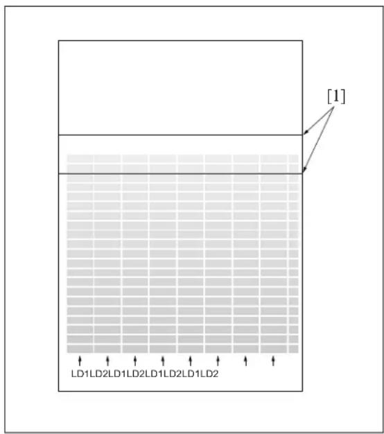
text_image
[1] LD1LD2LD1LD2LD1LD2LD1LD2[1]Reference line
- If it is not within specification, press the # button while holding down the * button.
- "LD2 offset adjustment screen"
Enter the offset value through the numeric keys and press the [SET] key.
- Setting range: -128 \~ +127
- Repeat the procedures 4 to 7 until the specified value is attained.
- Press the [RETURN] key to return to the "36 mode menu screen".
8.8 Timing Adjustment
This function adjusts each timing. When timing adjustment is performed, use A3 or 11 x 17 size paper.
A. Procedure
- Select [2. Timing adj.] in the "36 mode menu screen".
The “Timing adjustment menu screen” will appear.
- The following items are included in the timing adjustment.
"1 Vertical/horizontal magnification adjustment"
"2 Restart timing adjustment"
"3 Paper feed loop amount adjustment"
"4 Leading edge original erasure amount adjustment"
"5 Centering adjustment"
"6 Image read point adjustment"
"7 Restoring standard data"
-
Press the item key to be adjusted. The selected setting screen will appear.
-
Press the [RETURN] key in each of the timing adjustment screens to return to the "Timing adjustment menu screen".
8.8.1 Vertical/Horizontal magnification adjustment
The vertical and horizontal magnifications of the printer system and the copy system are adjusted.
A. Procedure
- Select [2. Timing adj.] in the "36 mode menu screen".
The “Timing adjustment menu screen” will appear.
- Select the [1. Drum clock adj.] on the "Timing adjustment menu screen".
The “Drum clock adjustment (vertical/horizontal magnification adjustment)” will appear.
- This adjustment has the following items. These can be selected by pressing the arrow key:
• Vertical magnification adjustment : Printer
• Vertical magnification adjustment : Printer 2
• Vertical magnification adjustment : Platen
• Horizontal magnification adjustment : Platen
- Vertical magnification adjustment : RADF (single side, 50%)
• Vertical magnification adjustment : RADF (single side, 100%)
• Vertical magnification adjustment : RADF (single side, 200%)
• Vertical magnification adjustment : RADF (single side, 400%)
- Vertical magnification adjustment : RADF (double side, 50%)
- Vertical magnification adjustment : RADF (double side, 100%)
- Vertical magnification adjustment : RADF (double side, 200%)
- Vertical magnification adjustment : RADF (double side, 400%)
-
Enter data from the numeric keys on the screen, then press the [SET] key to enter the data that have been entered.
-
Press the [COPY] key to return to the basic screen, then make a test copy.
-
Press the # button while pressing the * button to return to the Vertical/Horizontal magnification adjustment screen.
-
Press the [RETURN] key in the "Vertical and horizontal magnification adjustment screen" to return to the "Timing adjustment menu screen".
(1) Printer vertical magnification adjustment
With the amount of the paper feed loop adjusted properly between the registration roller and the fixing roller, the transfer slippage in the position about 20mm from the trailing edge of the transfer paper is prevented.
a. Procedure
- Enter the 36 mode.
2."36 mode menu screen"
Press the [2. Timing adj.] key.
- "Timing adjustment menu screen"
Press the [1. Drum clock adj.] key.
- "Timing adjustment screen"
Press the arrow key until "Vertical magnification-printer" appears in the message display area.
- "Vertical/horizontal magnification (drum clock) adjustment screen"
Press the [COPY] key.
6."Basic screen"
Set the copy size to A3 or 11 x 17, and the copy quantity to 5, then press the START button and output an test pattern (No. 9).
- Output five sheets of paper, and check for transfer jitter.
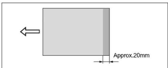
text_image
Approx.20mmCheck the transfer jitter at a point approx. 20mm from the trailing edge of the paper.
-
If it is not within specification, press the # button while holding down the * button.
-
"Vertical/horizontal magnification (drum clock) adjustment screen"
Enter a value through the numeric keys (the change of a value should be made in two steps) and press the [SET] key.
- Setting range: -50 (reduction) \~ +50 (enlargement)

1 step = 0.1%
-
Repeat steps 5 to 9 until the transfer jitter in all five output sheets disappears.
-
Once you have confirmed that there is no transfer jitter, press the arrow key, then select "Printer 2" to adjust the vertical magnification of "Printer 2".
(2) Printer 2 vertical magnification adjustment
Adjust the vertical magnification of the printer system.
Note:
- Ensure that the printer's vertical magnification is adjusted before going ahead with this adjustment
a. Procedure
- Enter the 36 mode.
2."36 mode menu screen"
Press the [2. Timing adj.] key.
- "Timing adjustment menu screen"
Press the [1. Drum clock adj.] key.
- "Vertical/horizontal magnification (drum clock) adjustment screen"
Press the arrow key until "Vertical magnification-printer 2" appears in the message display area.
-
Press the [COPY] key.
-
"Basic screen"
Select A3 or 11 x 17 size paper, then press the START button to print the test pattern.
- Use a ruler to measure the vertical magnification.
• Standard value: 0.5% max (life size)
Within ± 1mm with respect to 205.7mm

text_image
205.7±-
If it is not within specification, press the # button while holding down the * button.
-
"Vertical/horizontal magnification (drum clock) adjustment screen"
Enter a value from the numeric keys, then press the [SET] key.
- Setting range: -50 (reduction) \~ +50 (enlargement)

1 step = 0.1%
- Repeat the procedures 5 to 9 until the specified value is attained.

11Press the [RETURN] key to return to the "Timing adjustment menu screen".
(3) Platen vertical magnification adjustment
Adjust the vertical magnification of the scanner system.
a. Procedure
- Enter the 36 mode.
2."36 mode menu screen"
Press the [2. Timing adj.] key.
- "Timing adjustment menu screen"
Press the [1. Drum clock adj.] key.
- "Vertical/horizontal magnification (drum clock) adjustment screen"
Press the arrow key until "Vertical magnification-platen" appears in the message display area.
- Press the [COPY] key.
- "Basic screen"
Set the new test chart on the original glass and select A3 or 11 x 17 size paper. Then press the START button.
- Use a ruler to measure the vertical magnification.
- Standard value: ± 0.5% max (life size)
Within ± 1mm with respect to 200mm
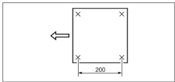
text_image
200- If it is not within specification, press the # button while holding down the * button.
- "Vertical/horizontal magnification (drum clock) adjustment screen"
Enter a value from the numeric keys, then press the [SET] key.
- Setting range: -20 (reduction) \~ +20 (enlargement)
1 step = 0.05%
-
Repeat steps 5 to 9 until the vertical magnification becomes the standard value.
-
Press the [RETURN] key to return to the "Timing adjustment menu screen".
(4) Platen horizontal magnification adjustment
Adjust the horizontal magnification of the copy system.
Note:
- The result of the platen horizontal magnification will be reflected all the images read by scanner (RADF, platen).
a. Procedure
- Enter the 36 mode.
2."36 mode menu screen"
Press the [2. Timing adj.] key.
- "Timing adjustment menu screen"
Press the [1. Drum clock adj.] key.
- "Vertical/horizontal magnification (drum clock) adjustment screen"
Press the arrow key until "Horizontal magnification-platen" appears in the message display area.
- Press the [COPY] key.
- "Basic screen"
Set the new test chart on the original glass and select A3 or 11 x 17 size paper. Then press the START button.
- Use a ruler to measure the horizontal magnification.
- Standard value: ± 0.5% max (life size)
Within ± 1mm with respect to 200mm
text_image
200- Press the # button while pressing the * button to return to the "Vertical/horizontal magnification (drum clock) adjustment screen".
- "Vertical/horizontal magnification (drum clock) adjustment screen"
Enter a value from the numeric keys, then press the [SET] key.
-
Setting range: -10 (reduction) \~ +10 (enlargement) 1 step = 0.1%
-
Repeat steps 5 to 9 until the horizontal magnification becomes the standard value.
-
Press the [RETURN] key to return to the "Timing adjustment menu screen".
(5) RADF vertical magnification adjustment
Adjust the vertical magnification while in RADF copying.
a. Procedure
- Enter the 36 mode.
- "36 mode menu screen" Press the [Timing adj.] key.
- "Timing adjustment menu screen" Press the [1. Drum clock adj.] key.
- "Vertical/Horizontal magnification (drum clock) adjustment screen" Press the arrow key to select the magnification you want to adjust. The screen changes in the following order: Single sided 50% → 100% → 200% → 400% → Double sided 50% → 100% → 200% → 400%.
- Press the [COPY] key.
- Set the ADF adjustment chart on the RADF and select A3 or 11 x 17 size paper. Then press the START button.
- Use a ruler to measure the vertical magnification.
- Standard value: ± 0.5% max (life size)
Within ± 1.0mm with respect to 190mm
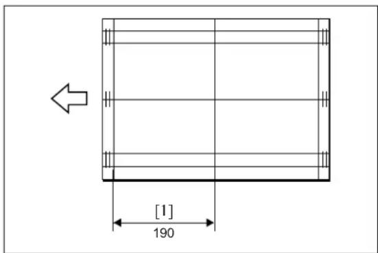
text_image
[1] 190[1]Vertical magnification
- If it is not within specification, press the # button while holding down the *button.
- "Vertical/Horizontal magnification (drum clock) adjustment screen" Enter a value from the numeric keys, then press the [SET] key.
- Setting range: -20 (reduction) \~ +20 (enlargement) 1 step = 0.1%
-
Repeat steps 5 to 9 until the vertical magnification becomes the standard value.
-
To adjust another adjustment item, press the arrow key to select the desired adjustment.
-
Press the [RETURN] key to return to the "Timing adjustment menu screen".
8.8.2 Restart timing adjustment
To adjust the restart timing.
A. Procedure
- Select the [2. Timing adj.] in the "36 mode menu screen", then the "Timing adjustment menu screen" will appear.
- Select the [2. Restart timing] on the "Timing adjustment menu screen". then the "Restart timing adjustment screen" will appear.
-
Using the arrow key will allow you to select the following items.
-
Restart timing adjustment : Engine (All)
- Restart timing adjustment : Engine (Main body upper tray)
- Restart timing adjustment : Engine (Main body lower tray)
- Restart timing adjustment : Engine (DB1)
- Restart timing adjustment : Engine (DB2)
- Restart timing adjustment : Engine (LCT)
- Restart timing adjustment : Engine (Bypass)
- Restart timing adjustment : Engine (ADU)
- Restart timing adjustment : RADF (single side)
- Restart timing adjustment : RADF (double side, front)
- Restart timing adjustment : RADF (double side, back)
-
Enter a desired value from the numeric keys on the screen, then press the [SET] key to validate your entry.
-
Turn on the Basic Screen by pressing the [COPY] key, then make a test copy from the basic screen.
- Press the # button while pressing the *button to return to the "Horizontal/Vertical magnification adjustment screen".
- Press the [RETURN] key in the "Restart timing adjustment screen" to return to the "Timing adjustment menu screen".
(1) Engine restart timing adjustment
a. Procedure
- Enter the 36 mode.
2."36 mode menu screen" Press the [2. Timing adj.] key. - "Timing adjustment menu screen" Press the [2. Restart timing] key.
- "Restart timing adjustment screen" Press the arrow key until the desired adjustment item appears in the message display area.
- Press the [COPY] key.
6."Basic screen"
Select a maximum paper size for the tray you want to adjust and press START to output the test pattern.
- Check the restart timing.
- Standard value: ± 2.0mm max.
- If it is not within specification, press the # button while holding down the * button.
- "Restart timing adjustment screen" Enter a value from the numeric keys, then press the [SET] key.
- Setting range: -127 (slow) \~ +127 (fast) 1 step = 0.1mm
- Repeat steps 5 to 9 until the restart timing becomes the standard value.
- To adjust another adjustment item, press the arrow key to select the desired adjustment.
- Press the [RETURN] key to return to the "Timing adjustment menu screen".
(2) RADF restart timing adjustment
Reference:
- The operation described here is the same as the adjustment in "36 mode menu screen" - [9. RADF adj.].
a. Procedure
- Enter the 36 mode.
2."36 mode menu screen"
Press the [2. Timing adj.] key.
- "Timing adjustment menu screen"
Press the [2. Restart timing] key.
- "Restart timing adjustment screen"
Press the arrow key until the desired RADF adjustment item appears in the message display area.
- Press the [COPY] key.
- "Basic screen"
Set the ADF adjustment chart on the RADF and select A3 or 11 x 17 size paper. Then press the START button.
- Adjustment the "RADF double side (second side)", then make a test copy in double side → single side mode and check the restart timing of 2nd output paper.
- Check the restart timing.
- Standard value: ± 3.0mm max. (life size)
- If it is not within specification, press the # button while holding down the * button.
- "Restart timing adjustment screen"
Enter a value from the numeric keys, then press the [SET] key.
- Setting range: -50 (slow) \~ +50 (fast) 1 step = 0.1mm
- Repeat steps 5 to 9 until the restart timing becomes the standard value.
- Press the [RETURN] key to return to the timing adjustment menu screen.
8.8.3 Paper feed loop amount adjustment
If a paper is skewed, adjust the amount of the loop for each tray.
A. Procedure
- Select the [2. Timing adj.] in the "36 mode menu screen", then the "Timing adjustment menu screen" will appear.
- Select the [3. Paper loop adj.] on the "36 mode menu screen", then the "Paper feed loop amount adjustment screen" will appear.
- Using the arrow key will allow you to select the following items.
• Paper feed loop adjustment : All
- Paper feed loop adjustment : Main body upper tray
- Paper feed loop adjustment : Main body lower tray (small size) B5 only
- Paper feed loop adjustment : Main body lower tray (large size) Other than B5
- Paper feed loop adjustment : DB upper tray (small size) Other than A3, B4, 11 x 17 and 8.5 x 14.
- Paper feed loop adjustment : DB upper tray (large size) A3, B4, 11 x 17 and 8.5 x 14
- Paper feed loop adjustment : DB lower tray (small size) Other than A3 and 11 x 17
- Paper feed loop adjustment : DB lower tray (large size) A3 and 11 x 17
• Paper feed loop adjustment : LCT
- Paper feed loop adjustment : Bypass (normal paper)
- Paper feed loop adjustment : Bypass (thick paper)
- Paper feed loop adjustment : Bypass (post card)
3 • Paper feed loop adjustment : ADU (excepting 8.5 x 5.5)
3 • Paper feed loop adjustment : ADU (8.5 x 5.5)
- Paper feed loop adjustment : RADF (single side)
- Enter a desired value from the numeric keys on the screen, then press the [SET] key to validate your entry.
-
Turn on the Basic Screen by pressing the [COPY] key, then make a test copy from the basic screen.
-
Press the # button while pressing the * button to return to the "Paper feed loop quantity adjustment screen".
- Press the [RETURN] key in the "Paper feed loop quantity adjustment screen" to return to the "Timing adjustment menu screen".
(1) Paper feed loop adjustment for engine
a. Procedure
- Enter the 36 mode.
2."36 mode menu screen"
Press the [2. Timing adj.] key.
- "Timing adjustment menu screen"
Press the [3. Paper loop adj.] key. - "Paper feed loop amount adjustment screen"
Press the arrow key until the desired adjustment item appears in the message display area. - Press the [COPY] key.
- "Basic screen"
Select a tray and a paper size properly and press START to output the test pattern.
- Check the skewing condition.
- When the paper feed loop quantity is not appropriate, press the # button while pressing the * button.
- "Paper feed loop amount adjustment screen"
Enter a value from the numeric keys, then press the [SET] key.
- Setting range: -100 \~ +15
1 step = 0.23mm
- Repeat steps 5 to 9 until the paper feed loop amount becomes appropriate.
- Press the [RETURN] key to return to the "Timing adjustment menu screen".
(2) Paper feed loop adjustment for RADF
1 Reference:
- The operation described here is the same as the adjustment in "36 mode menu screen" - [9. RADF adj.].
a. Procedure
- Enter the 36 mode.
2."36 mode menu screen"
Press the [2. Timing adj.] key.
- "Timing adjustment menu screen"
Press the [3. Paper loop adj.] key.
- "Paper feed loop amount adjustment screen"
Press the arrow key until "RADF" appears in the message display area.
- Press the [COPY] key.
- "Basic screen"
Set the ADF adjustment chart on the RADF and select A3 or 11 x 17 size paper. Then press the START button.
- Check the condition of skewing in the output copy.
- When the paper feed loop quantity is not appropriate, press the # button while pressing the * button.
- "Paper feed loop amount adjustment screen" Enter a value from the numeric keys, then press the [SET] key.
- Setting range: -10 (small) \~ +10 (large) 1 step = 0.5mm
- Repeat steps 5 to 9 until the skewing condition is correct.
- Press the [RETURN] key to return to the "Timing adjustment menu screen".
8.8.4 Leading edge original erasure adjustment
Adjust the leading edge original erasure (leading edge blank cut) amount.
Note:
- If you reduce the erasure width, a black line may appear on the leading edge of the paper when you make an enlarged copy.
A. Procedure
- Enter the 36 mode.
2."36 mode menu screen"
Press the [2. Timing adj.] key.
- "Timing adjustment menu screen"
Press the [4. Lead edge timing] key.
- "Leading edge original erasure adjustment screen"
Press the [COPY] key.
- "Basic screen"
Place the test chart on the platen glass. Select a maximum paper size for the tray you want to adjust and press START.
-
Measure the leading edge original erasure.
-
Standard value: Within 3.0mm
- If it is not within specification, press the # button while holding down the * button.
- "Leading edge original erasure adjustment screen"
Enter a value from the numeric keys, then press the [SET] key.
- Setting range: -20 (small) \~ +20 (large)
1 step = 0.1mm
- Repeat steps 4 to 8 until the leading edge original erasure amount becomes the standard value.
- Press the [RETURN] key to return to the "Timing adjustment menu screen".
8.8.5 Centering adjustment
In the centering adjustment, the centering of the image is adjusted in the direction at a right angle to the feed direction.
A. Procedure
- Select the [2. Timing adj.] in the "36 mode menu screen", then the "Timing adjustment menu screen" will appear.
- Select the [5. Centring adj.] on the "Timing adjustment menu screen", then the centering adjustment screen will appear.
- Using the arrow key will allow you to select the following items.
(1) Each of tray adjustments
- Centering adjustment : All
- Centering adjustment : Main body upper tray (common, small size, large size)
- Centering adjustment : Main body lower tray (common, small size, large size)
- Centering adjustment : DB upper tray (common, small size, large size)
- Centering adjustment : DB lower tray (common, small size, large size)
- Centering adjustment : LCT
- Centering adjustment : ADU (common, small size, large size)
- Centering adjustment : Bypass (common, small size, large size)
(2) Platen adjustment
- Centering adjustment : Platen
(3) RADF adjustment
- Centering adjustment : RADF (single side, double side front, double side back)
-
Enter a desired value from the numeric keys on the screen, then press the [SET] key to validate your entry.
-
Turn on the Basic Screen by pressing the [COPY] key, then make a test copy from the basic screen.
-
Press the # button while pressing the * button to return to the centering adjustment screen.
- Press the [Preceding screen] key in the "Centering adjustment screen" to return to the "Timing adjustment menu screen".
(1) Each tray centering adjustment
a. Procedure
- Enter the 36 mode.
2."36 mode menu screen" Press the [2. Timing adj.] key. -
"Timing adjustment menu screen" Press the [5. Centring adj.] key.
-
"Centering adjustment screen" Press the arrow key until the desired tray appears in the message display area.
-
Press the [COPY] key.
-
"Basic screen" Select A3 or 11 x 17 size paper, then press the START button to print the test pattern.
-
Fold the output at the center in the paper feed direction, and check that the left and right lines overlap completely.
-
Standard value: Within ± 2mm
-
If it is not within specification, press the # button while holding down the * button.
-
"Centering adjustment screen" Enter a value from the numeric keys, then press the [SET] key.
- Setting range: -53 (inward direction of the center line) \~ +53 (rear direction of the center line) 1 step = 0.09mm
- Repeat steps 5 to 9 until the miscentering is within standard value.
Note:
- If it can not be adjusted within the specified range, see "Other Adjustments".
-
To adjust another adjustment item, press the arrow key to select the desired adjustment.
-
Press the [RETURN] key to return to the "Timing adjustment menu screen".
(2) ADU centering adjustment
① Note:
- Be sure to perform the centering adjustment for each tray before starting this adjustment.
a. Procedure
- Enter the 36 mode.
2."36 mode menu screen"
Press the [2. Timing adj.] key.
- "Timing adjustment menu screen"
Press the [5. Centring adj.] key.
- "Centering adjustment screen"
Press the arrow key until "ADU" appears in the message display area.
-
Press the [COPY] key.
-
"Basic screen"
Select copy mode to single side → double side mode, then press the START button to print the test pattern.
- Fold the output at the center in the paper feed direction, and check that the left and right lines overlap completely.
- Standard value: Back : Within ± 3mm Front and back : Within ± 3mm
text_image
[1] [2][1]Lengthwise direction
[2]Miscentering amount between first side and second side
-
If it is not within specification, press the # button while holding down the * button.
-
"Centering adjustment screen"
Enter a value from the numeric keys, then press the [SET] key.
- Setting range: -53 (inward direction of the center line) \~ +53 (rear direction of the center line) 1 step = 0.09mm
-
Repeat steps 5 to 9 until the miscentering is within standard value.
-
To adjust another adjustment item, press the arrow key to select the desired adjustment.
-
Press the [RETURN] key to return to the "Timing adjustment menu screen".
(3) Platen centering adjustment

Note:
- Be sure to perform the centering adjustment for each tray before starting this adjustment.
a. Procedure
- Enter the 36 mode.
2."36 mode menu screen"
Press the [2. Timing adj.] key.
- "Timing adjustment menu screen"
Press the [5. Centring adj.] key.
- "Centering adjustment screen"
Press the arrow key until "Platen" appears in the message display area.
-
Press the [COPY] key.
-
"Basic screen"
Set the new test chart on the original glass and select A3 or 11 x 17 size paper, then press the START button.
- Check the miscentering by comparing the original with the copy.
- Standard value: Within ± 2mm
-
If it is not within specification, press the # button while holding down the * button.
-
"Centering adjustment screen"
Enter a value from the numeric keys, then press the [SET] key.
- Setting range: -74 (inward direction of the center line) \~ +74 (rear direction of the center line) 1 step = 0.04mm
-
Repeat steps 5 to 9 until the miscentering is within standard value.
-
Press the [RETURN] key to return to the "Timing adjustment menu screen".
(4) RADF centering adjustment

Note:
- Be sure to perform the centering adjustment for each tray before starting this adjustment.
a. Procedure
- Enter the 36 mode.
2."36 mode menu screen"
Press the [2. Timing adj.] key.
- "Timing adjustment menu screen"
Press the [5. Centring adj.] key.
- "Centering adjustment screen"
Press the arrow key until "RADF" appears in the message display area.
-
Press the [COPY] key.
-
"Basic screen"
Set the ADF adjustment chart on the RADF and select A3 or 11 x 17 size paper, then press the START button.
- Adjust the "RADF (double side (second side))", then make a test copy in double side → single side mode and check the loop amount of 2nd outputted paper.
- Check the miscentering by comparing the original with the copy.
- Standard value: Within ± 3mm
-
If it is not within specification, press the # button while holding down the * button.
-
"Centering adjustment screen"
Enter a value from the numeric keys, then press the [SET] key.
- Setting range: -74 (inward direction of the center line) \~ +74 (rear direction of the center line) 1 step = 0.04mm
-
Repeat steps 5 to 9 until the miscentering is within standard value.
-
Press the [RETURN] key to return to the "Timing adjustment menu screen".
8.8.6 Image read point adjustment
Adjust the image read point (leading edge timing).
For the image read position adjustment, the following two types are available:
- Platen adjustment
- RADF adjustment
Note:

- Be sure to perform the restart timing adjustment (engine) before starting this adjustment.
- The RADF read position adjustment is inhibited in the field.
- If you shift this value by a large amount, the RADF read density may change.
A. Procedure
- Enter the 36 mode.
2."36 mode menu screen"
Press the [2. Timing adj.] key.
- "Timing adjustment menu screen"
Press the [6. Read point adj.] key.
- "Image read point adjustment screen"
Select the "Platen adjustment", and press the [COPY] key.
- "Basic screen"
Set the new test chart on the original glass and select A3 or 11 x 17 size paper, then press the START button.
-
Make a comparison between original image and test copy image. Then check the image read point.
-
Standard value: 10 ± 1.0mm
- If it is not within specification, press the # button while holding down the * button.
- "Image read point adjustment screen"
Enter a value from the numeric keys, then press the [SET] key.
- Setting range: -20 (small) \~ +20 (large) 1 step = 0.1mm
- Repeat steps 5 to 9 until the image read point is within standard value.
- Press the [RETURN] key to return to the "Timing adjustment menu screen".
8.8.7 Recall standard data
Reset the adjusted set values of timing adjustment to the standard values (factory default data).
The following are included in the return to standard data:
- Recall standard data : Vertical/Horizontal magnification adjustment
- Recall standard data : Restart timing adjustment
- Recall standard data : Paper feed loop amount adjustment
- Recall standard data : Leading edge original erasure adjustment
- Recall standard data : Centering adjustment
- Recall standard data : Original read point adjustment
A. Procedure
- Enter the 36 mode.
2."36 mode menu screen"
Press the [2. Timing adj.] key.
- "Timing adjustment menu screen"
Press the [7. Factory default] key.
- "Resetting standard data screen"
Press the arrow key until the desired item appears in the message display area.
- Press the [YES] key to reset the set values to the standard values that have been selected and to return to the "Timing adjustment menu screen". Press the [NO] or [RETURN] key, then the set values are not reset and return to the "Timing adjustment menu screen".
- To reset another adjustment item, repeat steps 4 to 5.
- Press the [RETURN] key to return to the "Timing adjustment menu screen".
8.9 Running Test Mode
Conduct a test while in continuous copying operation.
Select the [3. Running mode] in the "36 mode menu screen", then the "Running test mode menu screen" will appear.
The following items can be selected:
A. Intermittent copy mode
In this mode, after the set number of copy operations has been completed, the machine goes into the copy ready status, waits 0.5 sec., then starts the same operation again.
B. Paperless intermittent copy mode
It makes copies at roughly the same timing as for a normal copy, without performing paper detection or jam detection. Also, like running mode 1, after the set number of copy operations has been completed, the machine goes into the copy ready status, waits 0.5 sec., then starts the same operation again.
C. Paperless mode
It makes copies at roughly the same timing as for a normal copy, without performing paper detection or jam dection.
D. Paperless/endless mode
It automatically sets the copy quantity to infinity. Also, like running mode 3, it makes copies at roughly the same timing as for a normal copy, without performing paper detection or jam detection.
E. Running mode
Running mode consists of paperless/endless mode plus an operation consisting of an optics each time scan and an automatic paper feed tray change.
8.9.1 Setting method
A. Procedure
- Enter the 36 mode.
- "36 mode menu screen" Press the [3. Running mode] key.
-
"Running test mode menu screen" Press the key according to the desired mode. (Mode 1 to Mode 5)
-
"Basic screen" Press the START button.
-
After checking the copy operation, press the Stop button to stop copy operation.
-
Press the # button while pressing the * button to return to the "Running mode menu screen".
-
To perform another running test mode, repeat steps 3 to 6.
-
Press the [RETURN] key to return to "36 mode menu screen".
8.10 Test Pattern Output
Output various test patterns and use the results to detach defective parts.
Select the [4. Test pattern] in the "36 mode menu screen", then the test pattern output screen will appear.
Note:
3 • For modes not listed specifically on the Service Manual, output should not be made.
A. Procedure
- Enter the 36 mode.
- "36 mode menu screen" Press the [4. Test pattern] key.
- "Test pattern output screen" Enter a pattern number to be output from numeric key.
- Press the [COPY] key.
- "Copy screen" Select A3 or 11 x 17 and press the start button to output a test pattern.
- When you want to output another test pattern, press the # button while pressing the * button and repeat the procedures 3 to 5 above.
- Press the [RETURN] key to return to the "36 mode menu screen".
No.1 Overall Halftone
[Check Items]
- When the density is set to 70 (halftone)
When there are white stripes, black stripes or uneven density found, check the printer system for any abnormality.
[Recommended checkpoints]: Developing unit, and cleaning unit - When the density is set to 0 (white)
When there is image gray back ground, check the printer system for any abnormality.
[Recommended checkpoints]: Charging corona, and high voltage contact - When the density is set at 255 (black)
When the density is thin, check the printer system for any abnormality.
[Recommended check point]: Write unit
* For information about setting the density, see "7.11 Test pattern density adjustment" below.
Test Pattern
When the density is set to 70 When the density is set to 0 When the density is set to 255

natural_image
Blank gray image with no visible content, text, or symbols
natural_image
Blank white image with a thin gray border (no text, symbols, or markings)
natural_image
Completely black image with no visible content, text, or symbols.No.5 Gradation Pattern
[Check Items]
- Check the pattern to see if the laser output of LD1/LD2 is uniform with the gradation continuously reproduced.
[Recommended checkpoints]: Write unit, and LD1/LD2 offset adjustment
* For LD1/LD2 offset adjustment, see "1. Process adjustment".
* Since a single beam is employed for 7235/7228/7222, the pattern shown as LD2 in the illustration below is also output by LD1.
Test Pattern

text_image
LD1LD2No.11 Beam Check
[Check Items 1]
- For development and analysis of the write unit
[Check Items 2]
- Check the solid black pattern to see if there is uneven density found in the main scanning and sub-scanning directions.
[Recommended checkpoints]: Charging corona, transfer/separation corona unit, and developing unit
[Check Items 3]
- Check to see if there is any image repelling in the gradation pattern at the leading/trailing edge of the test pattern in the feed direction.
[Recommended checkpoint]: Transfer/separation corona unit
Test Pattern
text_image
[1] [2][1] Solid black pattern
[2] Gradation pattern
No.16 Linearity Evaluation Pattern
[Check Items]
Judge from this test pattern which of the scanner system and the printer system is abnormal. Items that can be checked include horizontal magnification, vartical magnification, tilt image, and leading edge timing of the printer system. If the copy image is defective despite no abnormality being visible on the test pattern, the scanner system is defective.
Test Pattern

text_image
31mm 237mm [1] 20mm 190mm 190mm 280mm 280mm 205.7mm 205mm 190mm[1] Edge of pager
8.11 Test Pattern Density Adjustment
Density of respective patterns is adjusted in the following procedure.
A. Procedure
- Enter the 36 mode.
2."36 mode menu screen"
Press the [5. Density adj.] key.
- "Print density adjustment menu screen"
Press the [1. Print density adj. (1)] Key.
- "Print density adjustment screen"
Press the key according to the desired test pattern to be adjusted.
-
Enter a desired density by a numeric value from the numeric keys, then press the [SET] key. Input range : 000 (light) to +255 (dark).
-
Press the [COPY] key.
-
"Basic screen"
Press the START button to output a test pattern.
-
Check the density of the output test pattern.
-
Press the # button while pressing the * button to return to the "Print density adjustment screen".
-
To adjust another test pattern, repeat steps 4 to 9.
-
Press the [RETURN] key to return to "Print density adjustment menu screen".
8.12 Image Quality Adjustment
This function adjusts the image quality adjustment.
The following are shown on the image quality adjustment menu:
- RADF scan density adj.
• Non-image area erase check.
8.12.1 RADF scanning density adjustment
When the slit glass is replaced, adjust the density when reading the original with the RADF.
Note:
- The mechanical adjustment, optical adjustment and electrical adjustment of the scanner are completed.
- Make sure that the slit glass is cleaned.
- Make sure that the white chart is not dirty or folded.
A. Procedure
- Enter the 36 mode.
2."36 mode menu screen"
Press the [6. Image quality adj] key.
- "Image quality adjustment screen"
Press the [1. RADF Scan density adj.] key.
4."RADF Scanning density adjustment screen"
Set the white chart in A4 direction on the RADF.
- Press the [START] key.
- Check that "Completed" appears in the message display area.
- If "ERROR" appears in the message display area, then repeat steps 4 and 5.
Note:
- If "ERROR" is displayed repeatedly, there is a possibility of a defect in the adjustment of the scanner machine, optics, or electric-related parts.
- Press the [RETURN] key to return to the "Image quality adjustment screen".
8.12.2 Non-image area erase check
Carry out a survey of the installation environment after the machine is newly installed or moved to a different location.
Preparation:
- Be sure that the RADF is fully open.
- Do not place anything on the platen glass.
• The platen glass must not be dirty.
A. Procedure
- Enter the 36 mode.
- "36 mode menu screen" Press the [6. Image quality adj] key.
- "Image quality adjustment screen" Press the [2. Non-image Area Erase check] key.
- "Non-image area erase check screen" Press the [START] key.
- Confirm that "Operation OK" appears on the message display. If "Operation NG" appears, carry out non-original erasure installation survey once again while seeing to "Trouble and Remedy" below.
- Press the [RETURN] key to return to the "Image quality adjustment screen".
B.
(1) Warning-1
Adjust for Extreme Brightness. In many cases, the Nonimage-area-erase function will not operate correctly.
Please confirm "adjustment" - "36 mode" columns of the Service Manual.
(2) Remedy-1
If you use the non-original erasure function, or copy originals that have a dark background using the nonoriginal erasure method, relatively infrequently, use the machine in its present installation environment.
If, however, you copy originals that have a dark background fairly frequently, re-install the machine in a dark location and facing a direction such that external light does not get into it, then carry out the installation survey once again.
(3) Warning-2
A datum with potential not to function non-imagea-rea-erase is found.
Please confirm "adjustment" - "36 mode" columns of the Service Manual.
(4) Remedy-2
If you use the non-original erasure function relatively infrequently, you can use the machine in its present installation environment.
If, however, you copy originals that have a dark background fairly frequently, reinstall the machine in a dark location and facing a direction such that external light does not get into it, then carry out the installation survey once again. In this case, if there is a bright light source, such as a fluorescent light, directly above the machine, reconsider the installation location and direction, or take steps to block off the light from the light source (by using a cover, for example), then carry out the installation survey once again.
8.13 List Print
Select the [7. List Print] from the "36 mode menu screen" to display the list print menu screen.
You can select following menu options from this screen.
- Test pattern
- Font pattern
- Memory dump list
- Management list
- Adjustment list
- Log list (1)
- Log list (2)
- Analysing list
• E-Mail KRDS com.list

Note:
- Don't try to touch a mode not mentioned.
A. Test pattern
This option is used to output a grid pattern consisted of line width of 2 dots and line-to-line space of 500 dots. From this pattern, you can check the write system for normal performance.
B. Font pattern
This option outputs the font list built in the engine.
C. Memory dump list
This option is used to dump out data (in HEX and ASCII format) after the address specified in E-RDH memory (this list is referenced for troubleshooting).
D. Management list
This option outputs the machine status, counter information and history of jam and so on.
E. Adjustment list
This option outputs a list of current adjusting values in the 25/36 mode.
F. Log list (1)
The data from the memory is dumped in the HEX format and the ASCII format. (for analyzing trouble) Normally not used.
G. Log list (2)
The data from the memory is dumped in the HEX format and the ASCII format. (for analyzing trouble) Normally not used.
H. Analysing list
Outputs the necessary list prints together if trouble occurs in the field. (for analysing trouble) Normally not used.
(1) Procedure
- Enter the 36 mode.
2."36 mode menu screen"
Press the [7. List print] key.
3."List print menu screen"
Press the key corresponding to the desired menu option.
4."List print screen"
When outputting the memory dump list, specify the start and end addresses.
Note:
- The memory dump list is dump output in both the HEX and ASCII format.
-
Press the [COPY] key.
-
"Basic screen"
Press the [START] key to output the list.
-
Press the # button while depressing the * button to return to the list print screen.
-
When outputting another list, repeat above steps 3 to 7.
-
Press the [RETURN] key to return to the list print menu screen.

I. E-Mail KRDS com.list
This option outputs the result of the E-mail KRDS communication.
8.14 Counter Clear
The counter must be cleared whenever the drum or fixing parts/unit is replaced.
Select the [8. Counter Clear] from the 36 mode menu screen to display the counter clear screen.
Following menu options are available from this screen.
- Drum related counter (Drum counter, Drum drive counter).
- Fixing counter (Fixing web counter).
A. Procedure
- Enter the 36 mode.
- "36 mode menu screen" Press the [8. Counter clear] key.
- "Counter clear screen" Press the key corresponding to the item to be cleared.
- Message in the message display area will confirm if you really want to clear the item. Press the [YES] key. When the item is cleared, the "Counter clear screen" will be restored.
- When clearing another counter, repeat above steps 3 and 4.
- Press the [RETURN] key to return to "36 mode menu screen".
Reference:
- The operation here is the same as [2. PM count] - [3. Counter clear] on the "25 mode menu screen".
8.15 Adjustment of RADF
Adjustments of RADF are performed in the following procedures. For the adjustment, A3 or 11 x 17 copy paper should be used.
A. Procedure
- Select the [9. RADF adj.] from the "36 mode menu screen" to display the RADF adjustment menu.
The following are included in the RADF adjustment:
"1 Vertical/horizontal magnification (Drum clock) adjustment"
"2 Restart timing adjustment"
"3 Paper feed loop amount adjustment"
"4 Centering adjustment"
"5 RADF scanning density adjustment" - Press the key corresponding to the desired item. The screen corresponding to the selected item will appear.
- Press the [Preceding screen] key in each of the RADF adjustment screens to return to the "RADF adjustment menu screen".
8.15.1 Vertical magnification adjustment in RADF system
Adjust the vertical magnification of the RADF.
A. Procedure
- Select the [9. RADF adj.] from the "36 mode menu screen" to display the "RADF adjustment menu".
- Select [1. Drum clock adj.] from the "RADF adjustment menu" and the "Magnification screen" will appear.
- Using the arrow key will allow you to select the following items.
• Vertical magnification adjustment : RADF (single side, 50%)
• Vertical magnification adjustment : RADF (single side, 100%) - Vertical magnification adjustment : RADF (single side, 200%)
• Vertical magnification adjustment : RADF (single side, 400%)
• Vertical magnification adjustment : RADF (double side, 50%)
- Vertical magnification adjustment : RADF (double side, 100%)
- Vertical magnification adjustment : RADF (double side, 200%)
- Vertical magnification adjustment : RADF (double side, 400%)
4. Enter a desired value from the numeric keys on the screen, then press the [SET] key to validate your entry.
5. Turn on the Basic Screen by pressing the [COPY] key, then make a test copy from the basic screen.
6. Press the # button while depressing the * button to return to the "Magnification adjustment screen".
7. Press the [Preceding screen] key in the "Vertical/horizontal magnification adjustment screen" to return to the "RADF adjustment menu screen".
B. Vertical magnification adjustment in RADF system
Adjust the vertical magnification while in RADF copying.
a. Procedure
- Enter the 36 mode.
2."36 mode menu screen"
Press the [9. RADF adj.] key.
- "RADF adjustment menu screen"
Press the [1. Drum clock adj.] key.
- "Vertical/Horizontal magnification (drum clock) adjustment screen"
Press the arrow key to select the magnification you want to adjust.
The screen changes in the following order: Single sided 50% → 100% → 200% → 400% → Double sided 50% → 100% → 200% → 400%.
- Press the [COPY] key.
- Set the ADF adjustment chart on the RADF and select A3 or 11 x 17 size paper. Then press the START button.
- Use a ruler to measure the vertical magnification.
- Standard value: ± 0.5% max (life size)
Within ± 1.0mm with respect to 190mm
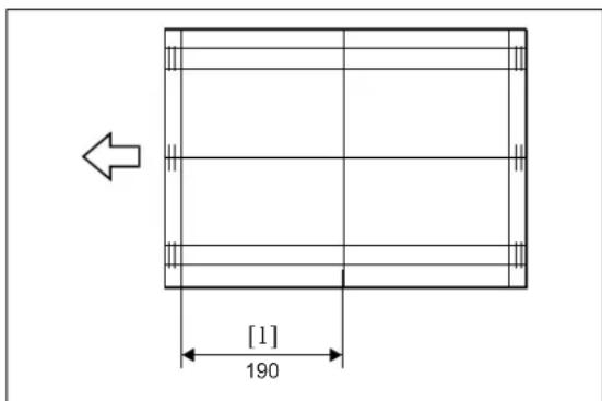
text_image
[1] 190[1] Vertical magnification
- If it is not within specification, press the # button while holding down the * button.
- "Vertical/Horizontal magnification (drum clock) adjustment screen" Enter a value from the numeric keys, then press the [SET] key.
- Setting range: -20 (reduction) \~ +20 (enlargement)
$$ 1 \text { step } = 0.1 \% $$
-
Repeat steps 5 to 9 until the vertical magnification becomes the standard value.
-
To adjust another adjustment item, press the arrow key to select the desired adjustment.
- Press the [RETURN] key to return to the "RADF adjustment menu screen".
8.15.2 Adjustment of restart timing
Use the following procedure to adjust the RADF restart timing.
A. Procedure
- Select the [9. RADF adj.] from the "36 mode menu screen" to display the "RADF adjustment menu".
-
Select [2. Restart timing] from the "RADF adjustment menu" and the "Re-start timing adjustment screen" will appear.
-
Using the arrow key will allow you to select the following items.
- Restart timing adjustment : RADF (single side)
- Restart timing adjustment : RADF (double side, front)
- Restart timing adjustment : RADF (double side, back)
-
Enter a desired value from the numeric keys on the screen, then press the [SET] key to validate your entry.
-
Turn on the Basic Screen by pressing the [COPY] key, then make a test copy from the basic screen.
-
Check the restart timing.
Standard value: -3.0mm maximum (Life size).
-
If it is not within specification, press the # button while depressing the * button
-
"Restart timing adjustment screen"
Enter the value from the numeric keys, then press the [SET] key.
- Setting range: -50 (delays the timing) \~ +50 (advances the timing) 1 step = 0.1mm
-
Repeat steps 5 to 9 until the re-start timing meets the standard value.
-
Press the [RETURN] key in the "Restart timing adjustment screen" to return to the "RADF adjustment menu screen".
8.15.3 Paper feed loop adjustment
1 Reference:
- The operation described here is the same as the adjustment in "36 mode menu screen" -[2. Timing adjustment].
Adjust the paper feed loop quantity while in RADF copying.
A. Procedure
-
Enter the 36 mode.
-
"36 mode menu screen" Press the [9. RADF adj.] key.
-
"RADF adjustment menu screen" Press the [3. Paper Loop adj.] key.
-
"Paper feed loop amount adjustment screen" Press the [COPY] key.
-
"Basic screen" Set the ADF adjustment chart on the RADF and select A3 or 11 x 17 size paper. Then press the START button.
-
Check paper feed loop volume.
-
When the paper feed loop quantity is not appropriate, press the # button while pressing the * button.
-
"Paper feed loop amount adjustment screen" Enter a value from the numeric keys, then press the [SET] key.
- Setting range: -10 (decrease) \~ 00 (standard) \~ +10 (increase) 1 step = 0.5mm
-
Repeat above steps 4 to 8 until an appropriate paper feed loop volume is obtained.
-
Press the [RETURN] key to return to the "RADF adjustment menu screen".
8.15.4 Centering adjustment
① Reference:
- The operation described here is the same as the adjustment in "36 mode menu screen" -[2. Timing adjustment].
Adjust the centering of the image in the direction at a right angle to the original feed direction of the RADF. For adjustment items, the following three items can be selected:
- Centering adjustment : RADF (single side)
- Centering adjustment : RADF (double side, front)
- Centering adjustment : RADF (double side, back)
A. Procedure
- Enter the 36 mode.
2."36 mode menu screen"
Press the [9. RADF adj.] key.
-
"RADF adjustment menu screen" Press the [4. Centring adj.] key.
-
"Centering adjustment screen" Press the arrow key until the desired item appears in the message display area.
-
Press the [COPY] key.
-
"Basic screen"
Set the ADF adjustment chart on the RADF and select A3 or 11 x 17 size paper, then press the START button.
- When the RADF (double side, back) is selected, make copies from double side single side mode, and use the second for the adjustment.
- Check the miscentering by comparing the original with the copy.
- Standard value: Within ± 3mm
-
If it is not within specification, press the # button while holding down the *button.
-
"Centering adjustment screen"
Enter a value from the numeric keys, then press the [SET] key.
- Setting range: -74 (inward direction of the center line) \~ +74 (rear direction of the center line) 1 step = 0.04mm
-
Repeat steps 5 to 9 until the miscentering is within standard value.
-
Press the [RETURN] key to return to the "RADF adjustment menu screen".
8.15.5 RADF scanning density adjustment
Whenever the slit glass is replaced, its density in reading an original must be adjusted in the following manner.
Note:
- Before starting this operation, every adjustment must be completed for the scanner's mechanical, optical and electric system.
- Make sure that the slit glass must be cleaned.
- Make sure that the white chart is not stained or folded.
A. Procedure
- Enter the 36 mode.
2."36 mode menu screen"
Press the [9. RADF adj.] key.
3."RADF adjustment menu screen"
Press the [5. RADF Scan density adj.] key.
4. "RADF scanner density adjustment screen"
Set the white chart in A4 direction on the RADF.
5. Press the [START] key.
- Make sure that the message "Completed" is indicated in the message display area.
- If the message "ERROR" appears in the message display area, repeat above steps 4 and 5.
Note:
- If "ERROR" is displayed repeatedly, there is a possibility of a defect in the adjustment of the scanner machine, optics, or electric-related parts.
- Press the [RETURN] key to return to the "RADF adjustment menu screen".
8.15.6 RADF image read point adjustment
Adjust the original read position while in RADF copying.
Note:
- The RADF read position adjustment is inhibited in the field.
8.16 FNS Adjustment (FS-112 only)
Adjust the alignment plate position of the finisher. When the sheets of paper exited from the finisher are uneven, adjust the corresponding paper size.
A. Procedure
- Enter the 36 mode.
2."36 mode menu screen"
Press the [10. FNS adj.] key.
- "FNS adjustment menu screen"
Press [1. FNS alignment plate position adjustment (rear)] or [2. FNS alignment plate position adjustment (front)].
4."FNS matching plate position adjustment screen"
Press the arrow key until the target paper size of the adjustment is displayed.
- Press the [Copy screen] key to display the basic screen. Set the output setting to the group mode and press the [OK] key.
Conduct the test copy on the paper size in which irregularity occurs.
- Check the positions of the alignment plate and the paper from the paper exit side.
- When irregularity still recurs, press the # button while pressing the *button.
8."FNS matching plate position adjustment screen" Enter an adjusting value from the numeric keys, then press the [SET] key.
- Setting range: -10 \~ +10
1 step = 0.2mm
- To adjustment of another paper size, select it from the arrow keys, then repeat steps 4 to 7.
- Press the [RETURN] key to return to the "FNS adjustment menu screen".
8.17 FNS Adjustment (FS-114 only)
Perform each finisher adjustment.
8.17.1 Fold & Stitch position adjustment (SK-114)
Adjust the fold & stitch position of the saddle kit. It is adjusted when the stapling unit 1 or 2 is replaced, when the staple position is not correct, and when the staple tile adjustment is performed.
A. Procedure
- Enter the 36 mode.
③ 2."36 mode menu screen"
Press any key to return again to "36 mode menu screen". Only through this operation, [10. FNS adj.] is made effective.
Press the [10. FNS adj.] key.
- On the "FNS adj. menu screen", select [1. Fold&Stitch posit adj
- On the "Fold & Stitch posit adj. screen", select the paper size you want to adjust by using the arrow keys.
- Set five A4 originals in the ADF.
- Press the [Copy screen] key to output a fold&stitch sample.
- Fold the output sample along its crease.
- Check the distance between the fold and staple positions.
• Standard A, B: 0 ± 1.5mm


text_image
A Fold Exit direction 4511D528AA
text_image
B Fold Exit direction 4511D527AA- If it is not within the standard, press # button while pressing * button.
- On the "Fold & Stitch position adj. screen", enter a numeric value using the numeric keypad. Then, press [SET] key.
- Setting range: -10 \~ +10
1 step = 0.5mm
• In case of A: set a plus value
• In case of B: set a minus value
-
Repeat the steps 4 through 9 until the fold&stitch position comes within the standard range.
-
Press [RETURN] and go back to the "FNS adj. menu screen".
8.17.2 Fold position adjustment (SK-114)
Adjust the fold position of the saddle kit.
It is adjusted when the fold unit is replaced, when the fold position is incorrect, and when the folding tilt adjustment is performed.
A. Procedure
- Enter the 36 mode.
③ 2."36 mode menu screen"
Press any key to return again to "36 mode menu screen". Only through this operation, [10. FNS adj.] is made effective.
Press the [10. FNS adj.] key.
- On the "FNS adj. menu screen", select [2. Fold position adj.].
- On the "Fold position adj. screen", select the paper size you want to adjust by using the arrow keys.
- Press the [Copy screen] key to output a fold sample.
- Fold the output sample along its crease.
- Check the misalignment.
• Standard A, B: 0 ± 1.5mm

text_image
Exit direction 4511D525AA
text_image
Exit direction B 4511D526AA- If it is not within the standard, press # button while pressing *button.
- On the "Fold position adj. screen", enter a numeric value using the numeric keypad. Then, press [SET] key.
- Setting range: -10 \~ +10
1 step = 0.5mm
• In case of A: set a plus value
• In case of B: set a minus value
-
Repeat the steps 4 through 8 until the fold position comes within the standard range.
-
Press [RETURN] and go back to the "FNS adj. menu screen".
8.17.3 Punch position adjustment (PK-114)
Adjust the hole positions of the punch kit.
A. Procedure
- Enter the 36 mode.
3 2."36 mode menu screen"
Press any key to return again to "36 mode menu screen". Only through this operation, [10. FNS adj.] is made effective. Press the [10. FNS adj.] key.
- On the "FNS adj. menu screen", select [3. Punch position adj.].
- Press the [Copy screen] key to output a punched sample.
- Check the hole positions on the sample.
• Standard A: 13 ± 3mm (2 holes)
9.5 ± 3mm (2 holes and 3 holes)
11 ± 3mm (4 holes)

text_image
Exit direction A [1][2] 7145fs1040
text_image
A [1][2] 7145fs1041
text_image
A [1][2] 7145fs1042
text_image
A [1][2] 7145fs1043-
If it is not within the standard, press # button while pressing * button.
-
On the "Punch position adj. screen", enter a numeric value using the numeric keypad. Then, press [SET] key.
-
Setting range: -10 \~ +10 1 step = 0.5mm
- To shift in [1] direction: set a plus value
-
To shift in [2] direction: set a minus value
-
Repeat the steps 4 through 7 until the punch positions come within the standard range.
-
Press [RETURN] and go back to the "FNS adj. menu screen".
8.17.4 Punch loop adjustment (PK-114)
Adjust the loop amount of the punch kit.
It is adjusted when the punch holes are tilted, or when paper frequently jams in punch mode.
A. Procedure
- Enter the 36 mode.
3 2."36 mode menu screen"
Press any key to return again to "36 mode menu screen". Only through this operation, [10. FNS adj.] is made effective.
Press the [10. FNS adj.] key.
- On the "FNS adj. menu screen", select [4. Punch loop adj.].
- On the "Punch loop adj. screen", select the paper size you want to adjust by using the arrow keys.
- Press the [Copy screen] key to output a punched sample.
- Check the tilt of holes on the sample.
- If the holes are tilted, press # button while pressing * button.
- On the "Punch loop adj. screen", enter a numeric value using the numeric keypad. Then, press [SET] key.
- Setting range: -4 \~ +4 1 step = 1.0mm
[2][1] 7145fs1044
[2][1] 7145fs1045
- When the punch part JAM occurs frequently: set a minus value
- When inclination is in a punch hole: set a plus value (In both the cases of [1] and [2], it sets to plus side.)
- Repeat the steps 4 through 7 until there is no tilt.
- Press [RETURN] and go back to the "FNS adj. menu screen".
9.47 MODE
9.1 47 Mode Setting Method
A. 47 Mode
This mode provides self-diagnostic functions (input/output check function) to check and adjustment the various signals and loads.
B. Operation method (to start 47 mode)
(1) 47 Mode startup
a. Turn the SW2 (Sub power switch) OFF.
b. Turn the SW2 ON while pressing 4 and 7 of the copy quantity setting buttons. If security enhancement is enabled, input CE password.
c. The moment "I/O check mode" is displayed in the message display area at the center of the screen, check to see if the 47 mode is activated.
"47 mode menu screen"

text_image
I/O check mode I/O check mode I/O CHECK MODE < 0 - 000 > IN: —— OUT: —— [1][2][3][4][1] Input/Output check code
[2] Multi code
[3] Input check
[4] Output check
(2) Input check method
a. Using the numeric keys, enter the code input for the desired signal (sensor, etc.) to check.
b. When using the multi mode, press the * button and enter the multi code according to the desired input check item (signal) with the numeric keys.
c. Procedure
- Enter the 47 mode.
2."47 mode menu screen"
Using the numeric keys, enter the input check code. *1
-
When using the multi mode, press the * button.
-
Using the numeric keys, enter the multi code. *1
5.Input check result will appear in the input check result display area.
- To check other signal input check, repeat steps 2 to 5.
*1 See "[5] Input check list".
(3) Output check method
a. Enter the output code (see the input/output check code) of the operating load you want to check with the number of sheets setting button.
b. When using the multi mode, press the * button and enter the multi code according to the desired output check item (load).
c. Press the [START] key to perform the output check.
d. To end the output check, press the [STOP] key.
e. Procedure
- Enter the 47 mode.
2."47 mode menu screen"
Using the numeric keys, enter the output check code.*2
-
When using the multi mode, press the * button.
-
Using the numeric keys, enter the multi code. *2
-
Press the [START] key to perform the output check.
-
To end the output check, press the [STOP] key.
-
To make another output check, repeat steps 2 to 6.
*2 See "[6] Output check list".
(4) Exiting the 47 mode
To end the 47 mode, turn the SW2 OFF.
9.2 RADF Original Size Detection
This adjustment is done when RADF fails to correctly detect size of an original.
A. Procedure
- Enter the 47 mode.
2."47 mode menu screen"
Press "69" by means of the numeric keys.
Check that "069-000" appears in the message display area.
-
Set the original guide plate to the minimum size (width) position, then press the [START] key.
-
To end the output check, press the [STOP] key.
-
Press the *button.
6.Enter "1" from the numeric keys.
Make sure that "069-001" is indicated in the message display area.
-
Set the original guide plate to the maximum size (width) position, then press the [START] key.
-
To end the output check, press the [STOP] key.
-
To end the 47 mode, turn the SW2 OFF.
9.3 Bypass Size Detection Adjustment
Perform this adjustment if paper size detection at the bypass feed tray does not function correctly.
A. Procedure
- Enter the 47 mode.
2."47 mode menu screen"
Press "28" by means of the numeric keys.
Check that "028-000" appears in the message display area.
-
Set a sheet of A4R paper in the bypass tray.
-
Press the * button.
-
Press [1] by means of the numeric keys.
Check that "028-001" appears in the message display area.
-
Press the [START] key.
-
Press the [STOP] key.
-
Set a sheet of A4 paper in the bypass tray.
-
Press the * button.
-
Press "2" by means of the numeric keys.
Check that "028-002" appears in the message display area.
-
Press the [START] key.
-
To end the output check, press the [STOP] key.
-
Set a sheet of B6R paper in the Bypass tray.
-
Press the button.
-
Press [3] by means of the numeric keys.
Check that "028-003" appears in the message display area.
-
Press the [START] key.
-
Press the [STOP] key.
-
To end the 47 mode, turn the SW2 OFF.
9.4 Action for Mounting When Reinstalling the HDD
Removing the HDD for analysis of an abnormality and then reinstalling it after turning on and off the power may result in no recognition of the HDD. To avoid a condition like this, conduct this setting.
A. Procedure
- Enter the 47 mode.
2."47 mode setting screen"
Press the No. of sheets setting button to enter "15". Check to see if "015-000" is displayed in the message display column.
-
Press the * button.
-
Press the No. of sheets setting button to enter "97".
Check to see if "015-097" is displayed in the message display column.
-
Press the [START] key.
-
Press the [STOP] key to terminate the setting.
-
To end the 47 mode, turn the SW2 OFF.
Note:
- When the data is in nonconformity, an error may occur. In that case, execute the format (key operator mode).
9.5 Input Check List
| Classification | Symbol | Code Multi code Name Display | ||||
| ON OFF | ||||||
| Analog signal | TSCB 00 — Toner control sensor board (Drum temperature) | 0 to 255 | ||||
| TSCB 01 — Toner control sensor board 0 to 255 | ||||||
| TSCB 02 — Toner control sensor board 0 to 255 | ||||||
| TH1 03 — Fxing temperature sensor/1 0 to 255 | ||||||
| TH2 04 — Fxing temperature sensor/2 0 to 255 | ||||||
| TDS 05 — Toner temperature sensor 0 to 255 | ||||||
| HUM1 | 06 — Humidity sensor | 0 to 255 | ||||
| Paper feed | PS8 | 10 | 1 | No paper sensor/U | Paper | No paper |
| PS11 | 2 | No paper sensor/L | ||||
| PS103 | 3 | No paper sensor/3 | ||||
| PS108 | 4 | No paper sensor/4 | ||||
| PS13 | 5 | Bypass tray no paper sensor | No paper | Paper | ||
| PS153 | 6 | No paper sensor (LT-203) | ||||
| PS7 12 | 1 Upper limit sensor/U | Upper limit | Not at upper limit | |||
| PS10 | 2 | Upper limit sensor/L | ||||
| PS102 | 3 | Tray upper limit sensor/3 | ||||
| PS107 | 4 | Tray upper limit sensor/4 | ||||
| PS152 | 6 | Tray upper limit sensor (LT-203) | ||||
| PS9 | 13 | 1 | Tray set sensor/U | Yes | No | |
| PS12 | 2 | Tray set sensor/L | ||||
| PS101 | 3 | Tray sensor/3 | ||||
| PS106 | 4 | Tray sensor/4 | ||||
| — | 16 | 1 | Main body upper tray paper size signal | 0 to 9*1 | ||
| — | 2 | Main body lower tray paper size signal | ||||
| PSDTB/3 | 3 | Paper size detection signal board/3 | ||||
| PSDTB/4 | 4 | Paper size detection signal board/4 | ||||
*1 Paper size signal (Inch)
| Tray | Symbol displayed | |||||||||
| 1 | 2 | 3 | 4 | 5 | 6 | 7 | 8 | 9 | 0 | |
| 1 | B5 | B4 | A5R | A4 | A4R | F4 | 5.5 × 8.5 | 8.5 × 11 | 8.5 × 11R | 8.5 × 14 |
| 2,3,4 | A5R | A4 | A4R | A3 | F4 | 5.5 × 8.5 | 8.5 × 11 | 8.5 × 11R | 8.5 × 14 | 11 × 17 |
*1 Paper size signal (Metric)
| Tray | Symbol displayed | |||||||||
| 1 | 2 | 3 | 4 | 5 | 6 | 7 | 8 | 9 | 0 | |
| 1 | B5 | B4 | A5R | A4 | A4R | F4 | 5.5 x 8.5 | 8.5 x 11 | 8.5 x 11R | 8.5 x 14 |
| 2,3,4 | B5 | B4 | A5R | A4 | A4R | A3 | F4 | 8.5 x 11 | 8.5 x 11R | 11 x 17 |
*1 Paper size signal (Common)
| Tray Symbol displayed | ||||||||||
| 1 | 2 | 3 | 4 | 5 | 6 | 7 | 8 | 9 | 0 | |
| LCT(3) | A4 A4R 8.5 x 11 | 8.5 x 11R | B5R B5 | A4 A4R | 8.5 x 11 | 8.5 x 11R | ||||
3
| Classification | Symbol | Code Multi code Name Display | ||||
| ON OFF | ||||||
| Paper feed • Conveyance | PS1 20 | 1 Registration sensor | Paper No paper | |||
| PS104 | 2 Paper feed sensor/U (DB upper tray) | |||||
| PS105 | 3 Paper feed sensor/L (DB lower tray) | |||||
| PS21 | 4 (7145/7235/7228) | Timing sensor/U (Main body upper tray) | ||||
| PS22 | 5 (7145/7235/7228) | Timing sensor/L (Main body lower tray) | ||||
| PS155 | 6 Paper feed sensor (LT-203) | |||||
| SW151 | 7 | Interlock switch (LT-203) | Open | |||
| PS2 22 | 1 Fixing exit sensor | Paper No paper | ||||
| SW3 | 23 1 Interlock switch | Open Close | ||||
| VR1 28 | 1 Bypass tray paper size | sensor VR 0 to 255 | ||||
| Scanner | — | 38 | 1 | Measured LD alarm value (LD1) | 0 to 255 | |
| — | 2 (7145) | Measured LD alarm value (LD2) | 0 to 255 | |||
| — | — (7235/7228/7222) | Measured LD alarm value | 0 to 255*2 | |||
| PS14 | 40 1 | (7145) | Scanner home position sensor | Other than H.P. | H.P. | |
| PS15 | 2 APS timing sensor | Open | Close | |||
| PS17 | 3 APS sensor | Original is provided | No original | |||
③ *2 The results can be displayed by pressing the start button → the stop button in this order.
| Classification | Symbol | Code Multi | code Name Display | |||
| ON OFF | ||||||
| Intrinsic functions | — 50 | 1 Check of F | DB serial communications(7145)Check of DF serial communications(7235/7228/7222) | 0001Normal | 0000Abnormalor notconnected | |
| — 2 Check of F | NS serial communications | |||||
| — 3 Check of s | canner serial communications | |||||
| — | 4(7235/7228/7222) | Check of Main drive board serial communications | ||||
| 51 1 Judging of the main body type — (7145) | 0096 to 0098*3(7235/7228/7222) | |||||
| — 2 Judging of the DB type 0 to 6 | *4 | |||||
| TLD 57 1 Toner level detector sensor Not provided | ||||||
| PS5 | ||||||
| RADF | PS301 | 60 | 1 | No original sensor | Paper | No paper |
| PS304 | 2 | Cover open/close sensor | Open | Close | ||
| PS303 | 3 DF open/close sensor Open | Close | ||||
| PS308 | 4 | Original registration sensor | No paper | Paper | ||
| PS309 | 5 Original conveyance sensor | |||||
| PS302 | 6 | Original exit sensor | Paper | No paper | ||
| PS305 | 7 Original size sensor/1 | |||||
| PS306 | 8 Original size sensor/2 | |||||
| VR301 | 9 Original size VR 0 to 255 | |||||

*3 Judging code of the Main type (7235/7228/7222)
| Display | 0096 | 0097 | 0098 |
| Judging type | 7222 | 7228 | 7235 |
*4 Judging code of the DB type
| Display | 0 | 2 | 3 | 5 | 6 |
| Judging type | Not connected | DB-211 | DB-411 | DB-211 + LT-203 | DB-411 + LT-203 |
| Classification | Symbol | Code Multi code Name Display | ||||
| ON OFF | ||||||
| FS-112 PS701 70 1 | Pressure | sensor (Level) | No | pressure | Pressure applied | |
| PS705 2 | Shutter sensor ON OFF | |||||
| PS701 3 | Pressure sensor (HP) No | pressure | Pressure applied | |||
| PS704 4 | Paper exit full sensor Other | than full | Full | |||
| PS703 8 | Exit sensor Paper No paper | |||||
| PS702 9 | FNS entrance censor | |||||
| PS712 | 24V detect | 10 | Stapler HP sensor | Other than H.P. | H.P. | |
| PS713 | 12 | Staple detection sensor | No staples provided | Staples provided | ||
| PS714 | 14 | Stapler ready sensor | Stapler not ready | Stapler ready | ||
| — 16 | ||||||
| PS711 | 17 | Tray upper limit sensor | Upper limit | Not at upper limit | ||
| PS706 | 18 | Tray lower limit sensor | Lower limit | Other than lower limit | ||
| PS707 | 19 | No paper sensor | Paper | No paper | ||
| PS708 | 20 | Stapler unit HP sensor | H.P. | Other than H.P. | ||
| PS709 | 21 | Alignment HP sensor/R | ||||
| PS710 | 22 | Alignment HP sensor/F | ||||
| FS-113 | PC1 | 70 | 1 | 1st tray exit sensor | Paper | No paper |
| PC3 | 2 Stacking sensor | |||||
| PC4 | 3 Upper path sensor | |||||
| PC2 | 4 Lower path sensor | |||||
| PC6 | 5 1st tray full detection sensor | |||||
| PC7 | 6 Elevate tray full detection sensor | |||||
| PC9 | 7 | Alignment HP sensor | H.P. | Other than H.P. | ||
| PC14 | 8 Staple home sensor | |||||
| PC12 | 9 Stacking roller home sensor | |||||
| PC13 10 | Paper exit roller home sensor | |||||
| PC5 | Process tray paper detection sensor | Paper | ||||
| — | 12 | Stapler 1 home sensor | ||||
| Classification | Symbol | Code | Multi code Name | Display | ||
| ON OFF | ||||||
| FS-113 — | 70 13 Staple empty detection sensor 1 No | staples provided | Staples provided | |||
| — 14 Self-priming sensor 1 Stapler | ready | Stapler not ready | ||||
| — 15 Stapler 2 home sensor H.P. Other | than H.P. | |||||
| — 16 Staple empty sensor 2 No | staples provided | Staples provided | ||||
| — 17 Self-priming sensor 2 Stapler | ready | Stapler not ready | ||||
| PWB-F 18 Elevate tray top face sensor Upper | limit | Not at upper limit | ||||
| PC8 19 Elevate tray paper extractor sensor ON OFF | ||||||
| S2, S3 | 20 Elevate tray upper limit/lower limit switch | Upper limit | Not at upper limit | |||
| PC10 | 21 Shift home sensor H.P. | Other | than H.P. | |||
| S4 | 22 Punch 2-hole/3-hole detection sensor (inch system only) | 2 holes | 3 holes | |||
| PC15 | 23 Punch motor pulse sensor ON | OFF | ||||
| PC11 | 24 Shift motor pulse sensor | |||||
| RU-101 | PS2 | 27 | Passage sensor | Paper | No paper | |
| FS-114 | PC4-FN 70 | 1 | Entrance sensor | Paper exists | No paper | |
| PC5-FN | 2 | Transport sensor | ||||
| PC6-FN | 3 | Alignment home position sensor 1 | Home position | Except home position | ||
| PC7-FN | 4 | Alignment home position sensor 2 | ||||
| S3-FN | 5 | Elevate tray upper/lower limit SW | Upper limit | Except upper limit | ||
| S2-FN | 6 | Shutter detection SW | Close | Open | ||
| S1-FN | 7 | Front cover open/close detection SW | ||||
| — | 9 | Pulse sensor | Shade | Transmit | ||
| PC23-SK | 10 In & out guide home position sensor Shade Transmit | |||||
| PC14-FN | 11 | Elevator tray lower limit sensor | Shade | Transmit | ||
| PC15-FN | 12 Top face detection sensor | |||||
| — 13 BK-114 detection | Equipped | Not equipped | ||||
| PC3-FN | 14 | Elevator tray position detect sensor | Shade | Transmit | ||
| FS-114 PC | C16-FN 70 | 15 Shutter home position sensor Home | position | Except home position | ||
| PC11-FN | 17 Exit padddle home position sensor | |||||
| PC12-FN | 18 Exit roll erer home position sensor | |||||
| PC8-FN | 19 Storage tray paper detect sensor | Paper exists | No paper | |||
| PC10-FN | 20 Staple home position sensor Shade Transmit | |||||
| — 21 | Self-priming sensor | |||||
| — 22 | Staple empty detection sensor | |||||
| — 23 | Staple hoeme sensor | |||||
| — 25 | Punch position sensor 1 Transmit Shade | |||||
| — 26 | Punch position sensor 2 | |||||
| PC1-PK | 27 Punch trash full sensor Shade Transmit | |||||
| PC22-SK | 28 Crease roller home position sensor Home | position | Except home position | |||
| S4-FN | 30 Layable guide home sensor Shade Transmit | Close | Open | |||
| PC26-SK | ||||||
| PC20-SK | 31 Saddle exit sensor | Paper exists | No paper | |||
| PC21-SK | 32 Saddle tray empty sensor | |||||
| — 33 | Saddle staple home position sensor 1 Shade Transmit | |||||
| — 34 | Saddle self-priming sensor 1 | |||||
| — | Saddle staple home position sensor 2 | |||||
| — 36 | Saddle self priming sensor 2 | |||||
| — | Saddle staple home position sensor 2 | |||||
| S4-SK | 38 | Saddle staple empty detection sensor 2 | ||||
| PC18-SK | 40 Saddle exit roller home position sensor | Open | Close | |||
| ADU | PS4 | 80 | — | ADU sensor | Open | Close |
9.6 Output Check List
| Classification | Symbol | Code Multi code Name | Cannot be set or changed in the field | |
| High voltage/image | L1 00 | — Exposure lamp | ||
| M4 01 | — Toner supply motor | 1 | ||
| M3 01 | (7145) | — Developing motor | ||
| M1 01 | — Main motor | |||
| SD9 01 | — Toner solenoid | |||
| HV 02 | — Charging X | |||
| 03 — Transfer X | ||||
| 04 — Separation (AC) X | ||||
| 05 — Transfer + Separation (AC + DC) X | ||||
| 06 — Separation (DC) | X | |||
| 07 — Grid | X | |||
| 08 — Dmax/γ LED | X | |||
| 10 (7145) | — Guide plate | X | ||
| 11 | — Bias (7145)Bias + Guide plate (7235/7228/7222) | X | ||
| PRMB | 15 | 1 | Service counter clear (Clears service related counter values from the PRMB (Parameter memory board)) | |
| 2 | Reuse counter clear (prohibited in the field) | |||
| 10 EKC data block clear | ||||
| 11 Job memory data block clear | ||||
| 12 Arbitrary replacement parts data block clear | ||||
| 13 | Coded dialing data block clear (for Fax) | |||
| 14 One touch data block clear (for Fax) | ||||
| 15 Group data block clear (for Fax) | ||||
| 16 Fax file format (for Fax) | ||||
| 17 FL related non-volatile data initialization (for Fax) | ||||
| 18 E-Mail address list clear | ||||
| 19 FTP address list clear | ||||
| 20 Box No. list clear | ||||
| 21 E-Mail Subject list clear | ||||
| 22 E-Mail Body list clear | ||||
| 23 Initialization of scanner file name | ||||
| 24 Initialization of copier file name | ||||
| 25 Initialization of SMB data | ||||
| 26 Initialization of LDAP data | ||||
| 90 Setting of system/copier and initialization of memory switch | ||||
| 97 HDD mounting measure |
3
3
3
3
3
| Classification | Symbol | Code | Multi code | Name | Cannot be set or changed in the field |
| High voltage/image | PRMB 15 98 Initialize KRDS non volatile area | ||||
| Paper feed | SD1 20 1 | 1st paper feed solenoid/U | |||
| SD2 2 | 1st paper feed solenoid/L | ||||
| SD3 3 | Bypass solenoid | ||||
| SD101 4 | Paper feed solenoid/U | ||||
| SD102 5 | Paper feed solenoid/L | ||||
| SD151 6 | LT Paper feed solenoid | ||||
| M9 21 | 1 Paper feed motor | ||||
| M100 2 | DB Paper feed motor | ||||
| M150 3 | LT Paper feed motor | ||||
| M9, MC1, MC2 | |||||
| M7 23 | 1 Tray motor/U | ||||
| M8 2 | Tray motor/L | ||||
| M101 3 | Tray up motor/3 | ||||
| M102 4 | Tray up motor/4 | ||||
| M151 5 | Tray up motor | ||||
| MC1 25 — Registration clutch | |||||
| MC2 26 — Loop clutch | |||||
| — | 28 | 1 | Bypass size adjustment (A4R in width) | ||
| — | 2 Bypass size adjustment (A4 in width) | ||||
| — | 3 | Bypass size adjustment (B6R in width) | |||
| SD7 29 — Separation claw solenoid | |||||
| Scanner | M2 31 | 1 Scanner motor | |||
| M5, FM7 (7235) | 32 1 Polygon motor (steady rotation) *1 | ||||
| M5, FM7 (7235) | |||||
| M2,L1 | 34 — Shading correction operation | ||||
| LD 36 — Laser PWM (0 to 255) | |||||
| LD,M5 | 37 — Conpel to laser ON | ||||
| LD,M5 | 38 — LD alarm measurement | ||||
| L1 | 39 — Platen still APS | ||||
| Main body | M11 | 40 — Fixing motor | |||
| M1 41 | 1 Main motor (sequential) | ||||
| M1 2 | Main motor (motor alone) | ||||
| FM3 | 42 1 Internal dehumidifying fan/1 | ||||
| FM4 | |||||
3
*1 7235 only, FM7 (Polygon cooling fan) also rotates at the same time.
3
3
3
3
3
| Classification | Symbol | Code | Multi code | Name | Cannot be set or changed in the field |
| Main body F | FM2 42 3 | DC powerDeveloping internal deCooling | (7145/7235) | Fixing cooling fan | |
| FM1 4 | supply cooling fan | ||||
| FM5 5 | suction fan | ||||
| FM6 6 | humidifying fan/2 | ||||
| FM3,FM6 | 7 Internal dehumidifying fan/1, 2 | ||||
| FM301 8 | fan | ||||
| FM7 9 | (7145) | Internal cooling fan/2 (low speed) | |||
| FM7 10 | (7145) | Internal cooling fan/2 (high speed) | |||
| TC 43 | — Total counter | ||||
| L2 45 | 1 Fixing heating lamp/1 | ||||
| L3 2 F | fixing heater lamp/2 | ||||
| Operation panel | OB 48 | — All LED ON | |||
| OB 49 | — Operation panel check (Checking for LCD, keys, and buzzer) | ||||
| Intrinsic functions | M3 50 | 0 Developing motor (motor alone) | |||
| M3 (7145) 1 to 255 Developing motor (sequential)• Use the multicode “1 to 255” to set the No. of rotations. | |||||
| PCL 51 | — | Pre-charging exposure lamp | |||
| TSL | 52 — Transfer synchronization lamp | ||||
| SD4 53 | — Clearing web solenoid | ||||
| M4 55 | 1 Toner supply motor 1 | ||||
| M4, SD9 | 2 Toner supply motor 1, Toner solenoid | ||||
| M10 56 | 1 Toner supply motor 2 (CW) | ||||
| M10 2 | Toner supply motor 2 (CCW) | ||||
| TLD | 57 — Toner level sensor | ||||
| SD9 58 | — Toner supply solenoid | ||||
| — | 59 — 24V power source remote | ||||
| RADF | M301 | 60 1 Original feed motor (CW) | |||
| M301 2 | Original feed motor (CCW) | ||||
| M303 | |||||
| M303 | |||||
| M302 5 | |||||
| M302 6 | |||||
| M302 7 | |||||
| SD302 8 | Rollar pressure solenoid | ||||
| SD301 9 | Paper exit solenoid | ||||
| SD303 | |||||
| VR301 | 69* | 0 Original size adjustment (small size) | |||
| VR301 1 | Original size adjustment (large size) | ||||
* Be sure to execute the operation without fail when DF-320 is installed.
3
3
3
| Classification | Symbol | Code | Multi code | Name | Cannot be set or changed in the field |
| FS-112 M | 701 70 1 | FNS conv | eyance motor | ||
| M702 2 | Paper exit | it motor (forward rotation) | |||
| M702 3 | Paper exit | it motor (reverse rotation) | |||
| M707 4 | Pressure | motor (forward rotation) | |||
| M707 5 | Pressure | motor (reverse rotation) | |||
| M706 6 | Tray up | motor (raise) | |||
| M706 7 | Tray up | motor (lower) | |||
| M705 8 | Stapler sh | shift motor, (initialize) (A4/F) | |||
| M705 9 | Stapler sh | shift motor, (initialize)(A4/R) | |||
| M703,M704 | 10 Alignment motor/R,F (initialize) | ||||
| M703,M704 | 11 Alignment motor/R,F (A4 size position) | ||||
| M703,M704 | 12 Alignment motor/R,F (rocking) | ||||
| M708 1 | 3 Stapler | motor | |||
| FS-114 M | 1-FN | 70 1 | Exit motor | ||
| M2-FN | Transport motor | ||||
| M3-FN | Entrance motor | ||||
| M4-FN | 3 Alignment motor 1 | ||||
| M5-FN | Alignment motor 2 | ||||
| M11-FN | 5 Elevator | motor (up) | |||
| M11-FN | 6 Elevator | motor (down) | |||
| M12-FN | 7 Shutter | opening motor | |||
| M6-FN | 1 Exit open/close motor | ||||
| M9-SK | 2 Saddle | exit open/close motor | |||
| M7-FN | 7 Stapling | unit moving motor | |||
| M10-SK | 23 Crease motor | ||||
| SL1-FN | 53 Storage | paddle solenoid | |||
| SL2-FN | 54 Exit pad | ddle solenoid | |||
| — 78 | Punch motor | ||||
| — 79 | Punch motor | ||||
| IT | SD8 | 75 1 IT gate solenoid | |||
| ADU | M6 80 | 1 Forward | rotation (7145: 230mm/sec,7235: 180mm/sec, 7228/7222: 140mm/sec) | ||
| M6 | 2 Forward rotation (600mm/sec) | ||||
| M6 | 3 Reverse rotation (7145: 230mm/sec,7235: 180mm/sec, 7228/7222: 140mm/sec) | ||||
| M6 | 4 Reverse rotation (600mm/sec) | ||||
| SD5 | 83 | — ADU gate solenoid | |||
| Classification | Symbol | Code Multi code Name | Cannot be set or changed in the field | ||
| Others — | 90 — PM | counter clear | |||
| — | 9 | 1 | Process counter clear (prohibited in the field) | ||
| — | 1 | Drum counter clear (prohibited in the field) | |||
| — 92 | — PRMB | (Parameter memory board) initial-zation(Process initial set/prohibited in the field) | X | ||
| — 93 | — Initial settings | ||||
| — 95 | — Automatic adjustment | of L detection ref-erence value(prohibited in the field) | X | ||
| — 96 | — Process delivery completing setting (pro-hibited in the field) | X | |||
| — 97 | — Light distribution check | ||||
| — 98 | — After completion of process shipment,temporary initialization of the PRMB(Parameter memory board) | X | |||
| — 119 | — Network initialization | ||||
| — 121 | — | Initialize fax-related nonvolatile memory | |||
| — 197 | — E-RDH (DRAM) capacity display | ||||
| — 198 | — E-RDH (DRAM) capacity check | ||||
| — 999 | — Checking of status | control board (prohibited in the field) | X | ||
10. OTHER ADJUSTMENTS
Caution:
- Be sure the power cord has been unplugged from the wall outlet.
10.1 RADF Height Adjustment
A. Procedure
- Close the RADF.
- Open the open/close cover [1], then turn the RADF height adjustment screw [2] until the RADF height adjust pointer [3] comes to center of the scale divisions.
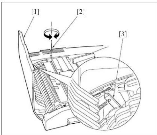
text_image
[1] [2] [3]10.2 RADF Distortion Adjustment
Adjust the amount of distortion of a copy in the following procedures.
A. Procedure
- Set a A3 paper on the tray of the main body.
- Set the ADF adjustment chart on the RADF, then make a copy.
- Check the amount of distortion in the copy. Standard value: ± 0.3% less.
text_image
[1] A B[1] Paper feed direction
-
When the distortion is larger than the tolerance, adjust it using the skew adjustment screw [1].
-
A: Turn the dskew adjustment screw [1] clockwise.
-
B: Turn the skew adjustment screw [1] counterclockwise.
-
Repeat above steps 2 to 4 until the standard value for distortion is met.

text_image
[1]10.3 RADF Original Skew Adjustment (Front Side)
When the front side of the originals are fed being skewed, adjust the registration pully bracket.
A. Procedure
- In the single sided → single sided copy mode, set the adjustment chart to the RADF for copying.
- Check the original skew pattern.
Standard value: Within ± 0.5%
text_image
[1] [3] [2] A B[1]Image
[2]Paper
[3]Paper feed direction
-
When the skew is not up to the standard, open the open/close cover [1], loosen the screw [3] and adjust the position of the registration pulley bracket[2].
-
A: Move the registration pully bracket [2] down [4].
• B: Move the registration pully bracket [2] up [5]. -
Repeat above steps 1 to 3 until the standard value for the skewed original is within standard value.
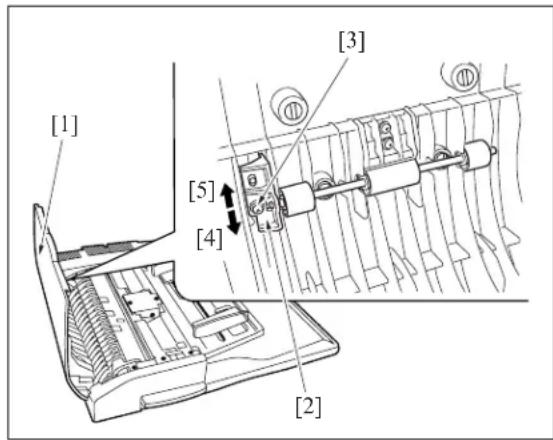
text_image
[1] [2] [3] [4] [5]10.4 RADF Original Skew Adjustment (Back Side)
When the back side of the original is supplied on a skew, adjust the clearance of the guide plate.
A. Procedure
- In the double sided → single sided copy mode, set the adjustment chart to the RADF for copying.
- Check the original skew pattern.
Standard value: Within ± 0.5%

text_image
[1] [2] [3] A B[1]Image
[2]Paper
[3]Paper feed direction
- When the skew is not up to the standards, open the open/close cover [1] and remove the 2 covers [2].
- Loosen the hexagon nut [3], and rotate the set screw[4] to adjust the clearance of the guide plate.
• A: Loosen the hexagon nut [3] at the rear and rotate the set screw [4] clockwise.
- B: Loosen the hexagon nut [3] at the front and rotate the set screw [4] clockwise.
Note:
- Since there is the possibility of jamming, be sure not make the clearance of the guide plate narrower than the standard value. (Be sure not to tighten the hexagon nut [3].)
-
The reference value of the clearance of the guide plate should be determined based on the position where the difference in level [A] of the second stage of the clearance reference block [5] becomes flush with the metal frame surface [B].
-
Repeat the steps 1 to 4 until the original skew gets within the standard value.
text_image
[5] A B [2] [1][2] [3] [4]10.5 DB-411 Paper-Centering Adjustment
Make a copy of the test chart, then perform necessary adjustment until the standard value for the paper centering is fit.
A. Procedure
- Loosen a screw [1] on the side guide situated at bottom of the paper feed tray. And also loosen the 2 screws [3] on the reinforcing plates (front/back) [2] situated at top of the tray.
- Rotate the adjusting cam [4], move the side guide back and forth and adjust it so that the centering of the image center [6] to the paper center [5] becomes within the specified value (within 3mm).
- When the adjustment is complete, tighten the screws provided for the side guide and reinforcing plates.
Note:
- If paper miscentering occurs, move the side guide forwards and backwards, and adjust the gap for the paper in use to between 1.0 and 1.5mm .
(The gap must be set so that the tray meets both the lower limit position and the upper limit position.)

text_image
[2] [3] [1] [4] [7] [6] [5]10.6 DB-411 Tray Tilt Adjustment
Normal paper feed can't be expected if the tray is tilted. In such case, adjust the tray and paper feed roller shaft so that they may be parallel in each other. Whenever the wire is replaced, this adjustment must be implemented.
A. Procedure
- Remove the front cover of the tray.
- Loosen a screw [2] of the wire adjustment part [1] situated in front side of the tray.

text_image
[1] [2]- Position in front and in rear the 2 metal scales [2] in the tray [1] as shown in the drawing.
- Move the wire adjustment part [3] until the distance from top of the side plate to the tray [1] top face is equal in both the front and back sides.
- When the adjustment is complete, tighten the screw [4] for the wire adjustment part [3].
text_image
[1] [3] [2] [4]10.7 LT Tray Tilt Adjustment
Normal paper feed can't be expected if the tray is tilted. In such case, adjust the tray and paper feed roller shaft so that they may be parallel in each other. Whenever the wire is replaced, this adjustment must be implemented.
A. Procedure
- Remove the LT from the main body.
2.Open the top cover and remove the right cover and the front cover. - Loosen a screw [2] of the wire adjustment part [1] situated in front.
natural_image
Mechanical assembly diagram showing a disassembly of a paper into a machine, with labeled parts [1] and [2] (no text or symbols beyond labels)- Position in front and in rear the 2 metal scales [2] in the tray [1] as shown in the drawing.
- Move the wire adjustment part [3] until the distance from top of the side plate to the tray [1] top face is equal in both the front and back sides.
- When the adjustment is complete, tighten the screw [4] for the wire adjustment part [3].
text_image
[1] [2] [3] [4]
10.8 FS-113 Output Check Mode
A. Switches on PWB
| S1 Used to run the Test Mode operation.S2 | |
| S3 DIP switch used to set the Test Mode operation. | |
| LED1~4 Turn ON or OFF, or blink to indicate a specific condition during Test Mode operations. | |

text_image
S3 S2 S1 LED1 LED2 LED3 LED4B. Test Mode
(1) Test Mode Setting Procedure
a. Procedure
- Turn OFF SW2 (Sub power switch) of the copier.
- Flip keys of the DIP switch into the ON or OFF position as necessary. (See Table below.)
- Turn ON SW2 (Sub power switch) of the copier.
- This sets the Finisher into the corresponding Test Mode operation.
b. Resetting Procedure
- Flip all keys of the DIP switch to their respective initial positions (OFF positions) and turn OFF, then ON, SW2 (Sub power switch) of the copier.
(2) Test Mode Operations
| Test Mode Operation | DIP Switch (S3) | LED | ||||||
| 1 | 2 | 3 | 4 | 1 | 2 | 3 | 4 | |
| Online ○ ○ | ○ | ● | ||||||
| 1st Tray exit ON | ● | ○ | ○ | ○ | ||||
| Elevator Tray exit | ON | ○ | ● | ○ | ○ | |||
| Finisher Tray exit | ON | ON | ● | ● | ○ | ○ | ||
| Shifting operation | ON | ON | ● | ○ | ● | ○ | ||
| Aligning Plate operation | ON | ON | ○ | ● | ● | ○ | ||
| Stapling Unit CD movement | ON | ON | ON | ● | ● | ● | ○ | |
| Exit Roller/ Rolls spacing | ON | ○ | ○ | ○ | ||||
| Storage Roller/ Rolls spacing | ON | ON | ● | ○ | ○ | ● | ||
| Elevator Tray operation | ON | ON | ○ | ● | ○ | ● | ||
| Hole Punch operation | ON | ON | ON | ● | ● | ○ | ● | |
| Hole position selection | ON | ON | ○ | ○ | ● | |||
| Sensor test | ON | ON | ON | Indicates sen-sor state | ||||
●: Blinking ○: OFF
(3) Operation in Each Test Mode Operation
a. 1st Tray Exit
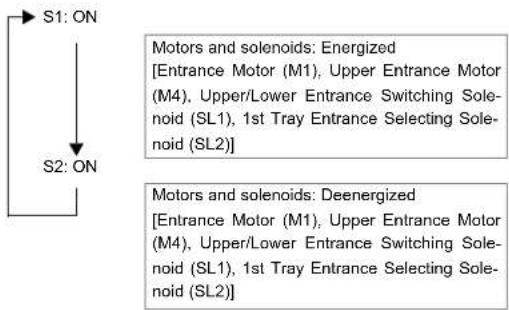
flowchart
graph TD
    S1["ON"] --> S2["ON"]
    S1 --> MotorsAndSolenoids["Ennergized\n[Entrance Motor (M1), Upper Entrance Motor (M4), Upper/Lower Entrance Switching Solenoid (SL1), 1st Tray Entrance Selecting Solenoid (SL2)"]]
    S2 --> MotorsAndSolenoids["Deenergized\n[Entrance Motor (M1), Upper Entrance Motor (M4), Upper/Lower Entrance Switching Solenoid (SL1), 1st Tray Entrance Selecting Solenoid (SL2)"]]
b. Elevator Tray Exit
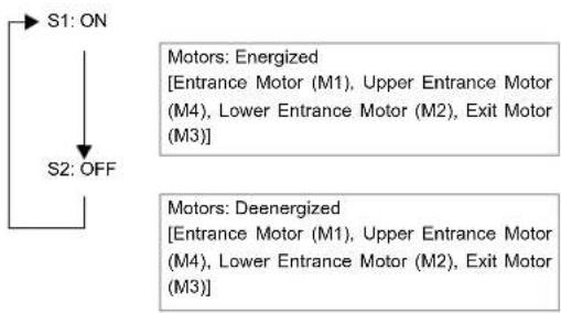
flowchart
graph TD
    A["S1: ON"] --> B["S2: OFF"]
    B --> C["Motors: Energized\n[Entrance Motor (M1), Upper Entrance Motor (M4), Lower Entrance Motor (M2), Exit Motor (M3)"]]
    B --> D["Motors: Deenergized\n[Entrance Motor (M1), Upper Entrance Motor (M4), Lower Entrance Motor (M2), Exit Motor (M3)"]]
c. Finisher Tray Exit

flowchart
graph TD
    A["S1: ON"] --> B["S2: OFF"]
    B --> C["Motors and solenoids: Energized\n[Entrance Motor (M1), Upper Entrance Motor (M4), Lower Entrance Motor (M2), Exit Motor (M3), Upper/Lower Entrance Switching Sole-noid (SL1)"]]
    B --> D["Motors and solenoids: Deenergized\n[Entrance Motor (M1), Upper Entrance Motor (M4), Lower Entrance Motor (M2), Exit Motor (M3), Upper/Lower Entrance Switching Sole-noid (SL1)"]]
d. Shifting Operation

flowchart
graph TD
    S1["ON"] --> S2["ON"]
    S1 --> TheElevatorTrayShiftsToFront
    S2 --> TheElevatorTrayShiftsToRear
e. Aligning Plate Operation
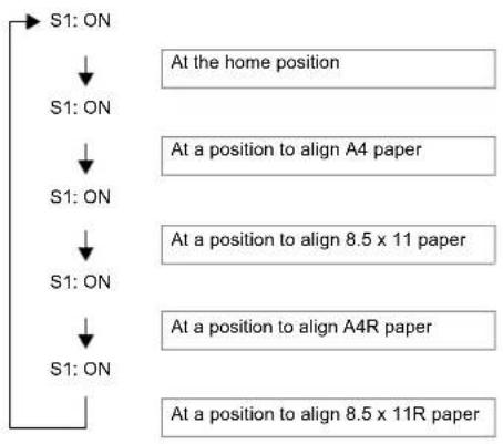
flowchart
graph TD
    A["S1: ON"] --> B["S1: ON"]
    B --> C["S1: ON"]
    C --> D["S1: ON"]
    D --> E["S1: ON"]
    E --> F["At the home position"]
    E --> G["At a position to align A4 paper"]
    E --> H["At a position to align 8.5 x 11 paper"]
    E --> I["At a position to align A4R paper"]
    E --> J["At a position to align 8.5 x 11R paper"]
f. Stapling Unit CD Movement
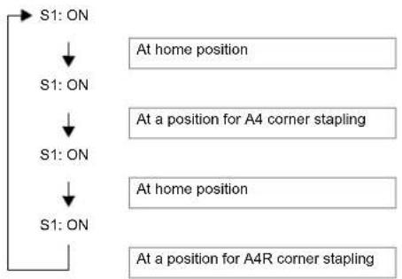
flowchart
graph TD
    A["S1: ON"] --> B["S1: ON"]
    B --> C["S1: ON"]
    C --> D["S1: ON"]
    D --> E["At a position for A4 corner stapling"]
    E --> F["At home position"]
    F --> G["At a position for A4R corner stapling"]
g. Exit Roller/Rolls Spacing

flowchart
graph TD
    A["S1: ON"] --> B["S2: ON"]
    B --> C["Pressed"]
    B --> D["Separated"]
h. Storage Roller/Rolls Spacing

flowchart
graph TD
    A["S1: ON"] --> B["S2: ON"]
    B --> C["Pressed"]
    B --> D["Separated"]
i. Elevator Tray Operation
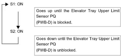
flowchart
graph TD
    S1["Start"] --> S2["State"]
    S2 -->|S1: ON| S1
    S2 -->|S2: ON| S1

    note1["Goes up until the Elevator Tray Upper Limit Sensor PQ\n(PWB-D) is blocked."]
    note2["Goes down until the Elevator Tray Upper Limit Sensor PQ\n(PWB-D) is unblocked."]
j. Hole Punch Operation

flowchart
graph TD
    A["S1: ON"] --> B["S1: ON"]
    B --> C["S2: ON"]
    D["The Punch Motor (M11) is energized."] --> E["The electromagnetic spring clutch is energized."]
    F["The Punch Motor (M11) is deenergized."] --> G["The Punch Motor (M11) is deenergized."]
k. Hole Position Selection U.S.A. and Canada
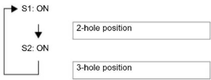
flowchart
graph TD
    S1[" S1: ON "] --> S2[" S2: ON "]
    S2 --> A[" "]
    style S1 fill:#f9f,stroke:#333
    style S2 fill:#ccf,stroke:#333
    note right of S2: 2-hole position
    note right of S2: 3-hole position
I. Sensor Test
| Sensor State LED | |||||
| 1 | 2 | 3 | 4 | ||
| Elevator Tray Upper Limit Sensor PQ (PWB-D) | Unblocked | ○ | ○ | ○ | ● |
| Storage Sensor (PC3) Blocked ○ ○ | ● | ○ | |||
| Lower Entrance Sensor (PC2) | Blocked ○ | ● | ○ | ○ | |
| Upper Entrance Sensor (PC4) | Blocked ● | ○ | ○ | ○ | |
●: ON ○: OFF
10.9 Lengthwise Position Adjustment of Punch Hole of FS-113
A. Procedure
- Set the copier into the Hole Punch mode and make a 1-sided copy from a 1-sided original.
- Fold the copy in half and check to see if the holes are aligned (deviation should be within 2mm).
- If the holes are misaligned, loosen the screw that secure the Punch Unit and slide the Punch Unit as necessary.
- Make a copy again and check for correct hole positions.
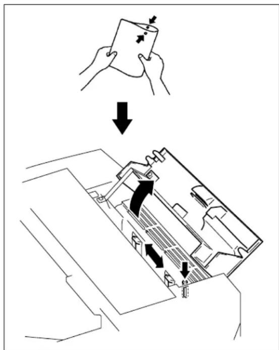
text_image
Diagram illustrating a device operation with labeled arrows indicating movement and assembly steps10.10 Adjustment of FS-113 Sole-noids
A. Adjustment of the Upper/Lower Entrance Switching Solenoid (SL1)
(1) Procedure
- Loosen one screw that secures the solenoid in position.
- Move the solenoid up or down and, when dimension A measures 4.4mm, tighten the screw.
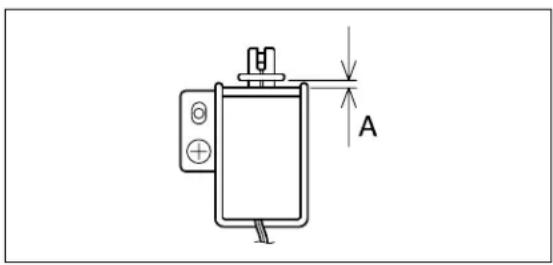
text_image
AB. Adjustment of the 1st Tray Entrance Selecting Solenoid (SL2)
(1) Procedure
- Loosen one screw that secures the solenoid in position.
- Move the solenoid to the right or left and, when dimension B measures 3.6mm, tighten the screw.
natural_image
Technical line drawing of a mechanical component with labeled dimension B (no text or symbols beyond basic geometry)10.11 FS-113 Timing Belt Tension Adjustment
A. Adjustment of the Upper Entrance Motor (M4) Timing Belt
(1) Procedure
- Loosen 2 screws.
- Use a spring balance to apply pressure at C and tighten the 2 screws at the position where the tension becomes 200 ± 100gf when the belt deflects 4mm.
B. Adjustment of the Lower Entrance Motor (M2) Timing Belt
(1) Procedure
- Loosen 2 screws.
- Use a spring balance to pull the square hole [2] given in the lower entrance motor mounting bracket with a force of 800 ± 50gf and tighten the 2 screws.
C. Adjustment of the Exit Motor (M3) Timing Belt
(1) Procedure
- Loosen 3 screws.
- Tighten the 3 screws at the position [3] where the external form of the screw [1] coincides with that of the oblong hole in the exit motor mounting bracket [3].
text_image
Technical diagram of a belt drive system with labeled components and directional arrows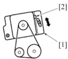
text_image
[2] [1]
text_image
[1] [2] [3]10.12 FS-113 Adjustment of the Elevator Tray Upper Limit Sensor
- This adjustment must be made when the Control Board (PWB-A) or the Elevate Tray Top Face Sensor (PWB-C, D) is replaced with a new one.
A. Procedure
- Set up the sensor test mode.
- Turn VR1 on PWB-A fully counterclockwise.
- Using a sheet of paper, block the Elevator Tray Upper Limit Sensor LED (PWB-C).
- Check that LED4 on PWB-A turns OFF. If it stays ON, slowly turn VR1 clockwise and stop turning it as soon as the LED turns OFF.
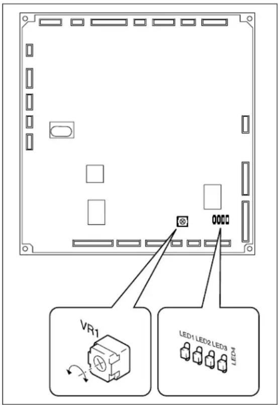
text_image
VR1 LED1 LED2 LED3 LED410.13 Adjustment of FS-113 Elevator Tray Overload Detection Level
- This adjustment must be made when the Control Board (PWB-A) or the Elevator Motor (M7) is replaced with a new one.
A. Procedure
- Set the "Elevator Tray operation" function of the Test Mode.
- Turn VR2 on PWB-A fully counterclockwise.
- Using a sheet of paper, block the Elevator Tray Upper Limit Sensor LED (PWB-C). Then using the "Elevator Tray operation" function, lower the Elevator Tray.
- Place 1,500 sheets of A3 (20lbs) or 3,000 sheets of A4 (20lbs) paper on the Elevator Tray.
- Using the "Elevator Tray operation" function, raise the Elevator Tray.
- While the Elevator Tray is going up, turn VR2 on PWB-A clockwise and, when LED3 on PWB-A turns from a steady light to off, stop turning VR2.
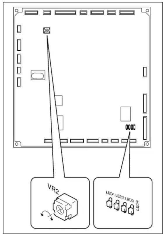
text_image
VR2 LED1 LED2 LED3 LED410.14 Staple Position Adjustment of FS-114
- It is replaced when the stapler is replaced or when the staple position is not correct.
A. Procedure
-
Set the staple mode and make a copy.
-
Check the staple position of the paper.
• 1-Point Tilted Staple
Paper Width 279 to 297mm: 45° tilt
| Measurement position | Specification Adjustment range |
| A, D 4.4 ± 3mm — | |
| B, C 12.1 ± 4mm +1mm to -2mm |
B5, B4: 30^ tilt
| Measurement position | Specification Adjustment range | |
| A 4.9 ± 3mm | — | |
| B 16.2 ± 4mm | +1mm to -2mm | |
| C 10.1 ± 4mm | +1mm to -2mm | |
| D 6.5 ± 3mm | — | |
• 1-Point Parallel Staple
Paper Width 182 to 216mm
| Measurement position | Specification A | Adjustment range |
| A 4.5 ± 3mm | — | |
| B 6.0 ± 4mm | +1mm to -2mm |
text_image
B A C D 4349D503AA
text_image
A B 4349D504AA• 2-Point Staple
| Measurement position | Specification Adjustment range | |
| C, F 6.0 ± 4mm | +1mm to -2mm | |
| D | Y | ± |
| E | X | ± |
Y = (paper width-x-11) / 2
X = A3, A4: 137
B4, B5: 114
A4R: 190
B5R: 162
4 4
Substitute above into the equation.
- If the staple position is misaligned, remove one screw and the cover.
- Loosen two adjustment screws and move the Stapler Unit in the direction of the arrow to make the adjustment.
- Make another copy and check the staple position.
text_image
C D m E m m m F 4349D505AA
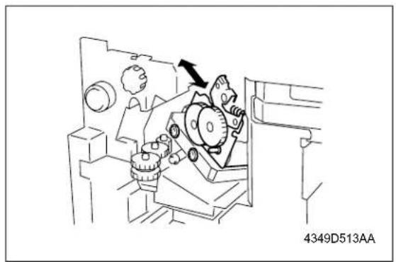
natural_image
Mechanical assembly diagram showing gears and a directional arrow (no text or symbols)10.15 Adjustment of the Installation Position of the Shutter Drive Gear of FS-114
- When the gear/1, 2 or 3 is replaced, or the gear/1, 2 or 3 is removed.
A. Procedure
- Set three gears.
Note:
- Set the gears so that the marks on Gears 1 and 3 are aligned with the rib of Gear 2 as shown on the right.
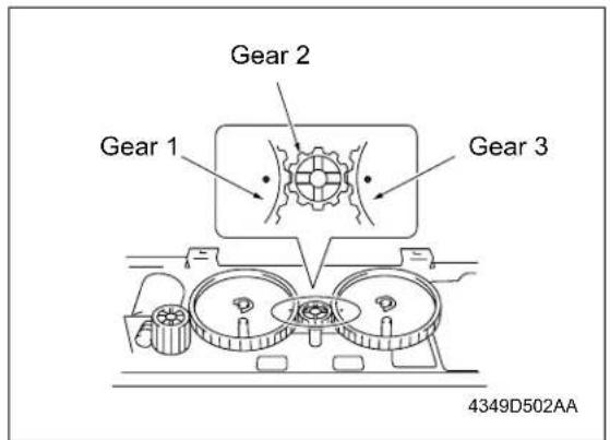
text_image
Gear 2 Gear 1 Gear 3 4349D502AA10.16 Punch Hole Deviance Adjustment of FS-114 (PK-114)
- When the punch kit is replaced or removed.
A. Procedure
- Set the copier into the Hole Punch mode and make a 1-sided copy from a 1-sided original.
- Fold the output paper in half and check whether the punch hole positions are aligned.
Specification: Within 2mm - If the punch hole position is misaligned, remove two screws and the cover.
- Loosen one adjustment screw and move the Punch Unit forward or backward to make the adjustment.
- Make another copy and check the punch hole position.
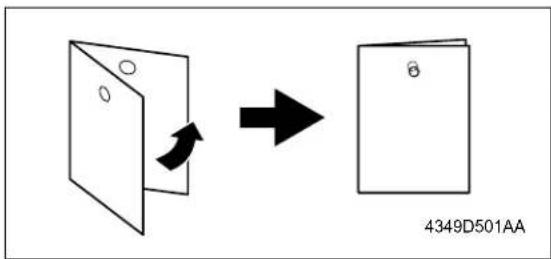
text_image
4349D501AA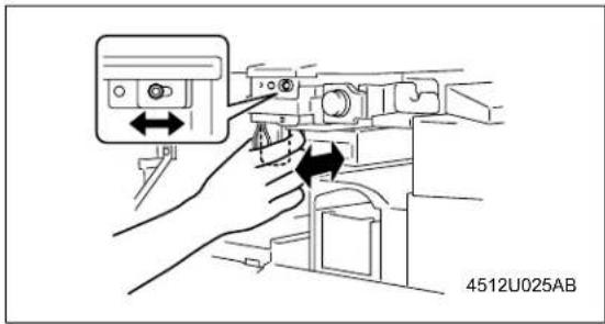
text_image
4512U025AB10.17 Fold Angle Adjustment of SK-114
- It is performed when the fold unit is replaced or a tilt occurs in paper folding.
A. Procedure
- Enter the Crease mode and make a copy. (A3 Size)
- Fold the output paper and half and check whether section A of the paper is aligned. Specification: 0 ± 1.5mm
-
If the fold position is slanted as shown on the left, make the following adjustment.
-
Open the Front Door, loosen one adjustment screw, and move the Crease Unit to the left to make the adjustment.
* If the fold position is slanted opposite to the figure of step 3, move the Crease Unit to the right to make the adjustment.
- Make another copy and check the fold position.

text_image
A Center Fold 4511D529AA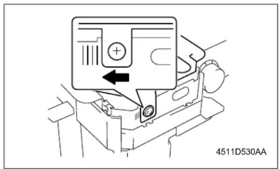
text_image
4511D530AA10.18 Staple Angle Adjustment of SK-114
- It is performed when the staple unit 1 or 2 is replaced or a tilt occurs in center staple position.
A. Procedure
- Set five A4 originals in the ADF.
- Set to 2-point Staple and Crease mode and make a copy. Check whether the staple position is aligned correctly. Specification: 0 ± 1.5mm
- If the staple position is slanted as shown on the figure, make the following adjustment.

text_image
A Exit direction 4511D531AA- Release the lock release lever of the Saddle Unit.
- Loosen one adjustment screw and move the lock lever to the left to make the adjustment.
* If the staple position is slanted opposite to the figure of step 3, move the lock lever to the right to make the adjustment. - Make another copy and check the staple position.

text_image
4511D532AAII ISW
1. DESCRIPTION OF THE ISW
The ISW (In-System Writer) is an operation by which the control program, that is stored in the flash ROM incorporated into a variety of control boards in the digital copier, is rewritten with the board integrated into the main body of the copier. Executing the ISW allows you to renew the version of the control program without changing the board or to install the latest program while changing the board.
As a tool to execute the ISW, you can use the [ISW Trns (PC software)] by which rewriting is made with a personal computer (PC) connected to the digital copier.
This tools allow direct rewriting of the control program in the flash ROM included in the copier main body by connecting the ISW connector of the copier main body.
The method of carrying out the necessary setup work on the main body for executing ISW is described here. For the operation of the "ISW Trns," see the "ISW (In-System Writer) Service Manual."
Note:

- When using the USB, be sure to turn on the USB radio button in the [Setting (S)] - [Communication setting (C)] of the ISWTrns and press the OK button.
- For the ISW method of this machine, only the ISW Trns is available.
2. SETUP
A. Board used for the ISW
The following boards are available for rewriting a program using the ISW in this machine.
• SCB (System control board)
• CB (Main body control board)
• FNSCB (FNS control board) : FS-112
• PWB-A FN (Main control board) : FS-114
- FAX control
- For the printer controller, see the Service Manual of IP.
For boards other than the above, the ROM is required to be changed.
B. Data flow
There are 2 types of data flows for the ISW as shown below:
• PC → SCB → CB → FNSCB/PWB-A FN
• P C → SCB → FAX
Important:
- When the overall control program has not been written into the SCB (System control board), it is not possible to rewrite programs for other boards.
C. Checking before transfer
Before executing the ISW, be sure to check to see if the transfer case and the transfer mode to be used are correct.
(1) When the overall control program has not been installed
When the overall control program has not been installed, the LCD screen is not displayed and data cannot be written in the 25 mode.
Transfer case: When the SCB (System control board) is being replaced.
Transfer mode: When the power is on. (When the data LED indicator lamp is on → The ISW is waiting for transfer. When the lamp is flashing → The ISW is receiving data.)
(2) When the overall control program has been installed
When the overall control program has been installed, it is possible to write data in the 25 mode.
Transfer case: Version up, when boards other than the SCB (System control board) are being replaced.
Transfer mode:25 mode
D. ISW connectors
The ISW connectors are provided on the right side of the main body, and each of the connectors is covered with a cap or seal. Be sure to remove this cap or seal while in use.
The following two types of IF are available:
- USB (B type)
- IEEE1284 (Nibble/ECP/compatible mode)
③ In the case of the 7145
natural_image
Exterior view of a printer unit with a magnified inset showing internal components (no text or symbols visible)3 In the case of the 7235/7228/7222
natural_image
Exterior view of a white office machine with a close-up inset showing internal components (no visible text or symbols)E. Preparation of the copying machine for ISW transfer
When the copier and the PC are USB connected for the first time, it is necessary to install the USB driver into the PC. (It is not required, however, to install the USB driver on and after the second connection.)
For details of the installation procedure of the USB driver, see "3. USB ISW."
Before operating the ISW, maintain the copier in ISW mode.
(1) When the overall control program has been installed
3 a. Procedure
- Enter the 25 mode.
2."25 mode menu screen"
Press the [10.ISW] key.
3."ISW menu screen"
Select the ROM where the ROM data to be rewritten.
[START] key is displayed.
- "Program rewrite screen"
Press the [START] key.
Note:
- This step is to be used only when carrying out the ISW to make a USB connection. When a connection method other than the above is used, proceed to Step 6.
5. "Program rewrite screen"
After confirming that a message "Reading program data" is to be displayed, disconnect once the USB cable that has been connected to the copier and then reconnect it again.
Note:
- The step is to be used only when carrying out the ISW to make a USB connection. When a connection method other than the above is used, proceed to Step 6.
6. "Program rewrite screen"
Pressing [START] key, cause the machine to be data waiting condition.
Note:
- When the ISW is carried out to make a USB connection, this step should be omitted.
- Execute the operation according to the procedures specified in the "ISW (In-System Writer) Service Manual."
- In about 60 seconds after the data transfer from the PC has been completed, the ISW data is written from the system memory in the SCB (System control board) into the flash ROM in which data is stored.
Note:
- When Steps 4 and 5 are not carried out to make a USB connection, the USB port is not opened and the data cannot be sent from the PC. When the normal operation of the ISW is not available, start all over again from Step 1 after turning the SW1 (main switch) OFF and ON.
-
Be sure not turn off the power to the copying machine while the ISW data is being written.
-
When data has been written into the flash ROM, the system is restarted to display the "25 mode menu screen."
(2) When the overall control program is not installed
- Turn on the SW1 (Main power switch) and the SW2 (Sub-power switch).
- Check to see if the data LED indicator lamp is on. In this condition, the ISW is placed in waiting for transfer.
Check to see if the data LED is flashing while the ISW data is being received.
- The procedure after this is the same as the steps above for “(1) When the overall control program has been installed”.
F. Data transfer error
When a transfer error occurs, an error mark is displayed in the message area on the LCD display.
If an error occurs, see the section "Error handling" in the separate "ISW Service Manual" and perform the appropriate countermeasures.
After the countermeasures are completed, perform the re-write operation again from the beginning.
(1) ISW for image control/FNS control/FAX control
3 a. Procedure
- Enter the 25 mode.
2."25 mode menu screen"
Press the [10. ISW] key.
3."ISW menu screen"
Select a ROM the data of which is rewritten. The [START] key is displayed.
- "Program rewrite screen"
Press the [START] key.
Note:
- This step is to be used only when carrying out the ISW to make a USB connection. When a connection method other than the above is used, proceed to Step 6.
- "Program rewrite screen"
After confirming that a message "Reading program data" is to be displayed, connect the USB cable.
Note:
- The step is to be used only when carrying out the ISW to make a USB connection. When a connection method other than the above is used, proceed to Step 6.
- "Program rewrite screen"
Press the [START] key to put the ISW into the state of waiting for transfer.

Note:
- When the ISW is carried out to make a USB connection, this step should be omitted.
- Execute the operation according to the procedure given in the ISW (In-system Writer) Service Manual.
- In about 100 seconds after completion of the transfer of data from the PC, the ISW data is written into the flash ROM in the ISW-intended board.

Note:
- When Steps 4 and 5 are not carried out to make a USB connection, the USB port is not opened and the data cannot be sent from the PC. When the normal operation of the ISW is not available, start all over again from Step 1 after turning the SW1 (main switch) OFF and ON.
-
Do not turn off the power to the copying machine while the ISW data is being written.
-
When the data has been written into the flash ROM, a message "Completed successfully" is displayed.
-
Press the [RETURN] key twice to return to the "25 mode menu screen".
3. USB ISW
The ISW RNs tool for transfer can be installed in the PC by using the setup disk. However, the USB driver (KCAUSB.SYS) is required to be installed by the plug-and-play of the Windows after connecting the PC and the copier with the USB cable.
The installation of the USB driver is required only when the PC is connected to the copier for the first time. (No installation is required on and after the second connection.)
A. Preparation for the installation of the USB driver
- Enter the 25 mode.
2."25 mode menu screen"
Press the [10.ISW] key.
- "ISW menu screen"
Select the ROM where the ROM data to be rewritten.
[START] key is displayed.
- "Program rewrite screen"
Pressing [START] key causes the machine to be data waiting condition.
- Connect the USB connector.
- The "Welcome to the Found New Hardware Wizard" display is shown.
(The succeeding steps of the "B. USB driver installation procedure (Windows 2000/XP)").
B. USB driver installation procedure (Windows 2000/XP)
When the PC and the copier are connected with the USB cable, the USB driver is automatically installed by the plug-and-play.
However, this may cause the USB driver (USBPRINT.SYS) of the Windows to be installed. Accordingly, the USB driver should be set by following the procedure given below:
- Select "Install from a list or specific location [Advanced]" in the display shown below, and then click [Next].

text_image
Found New Hardware Wizard Welcome to the Found New Hardware Wizard This wizard helps you install software for: KONICA MINOLTA7222-7235/IP-424 If your hardware came with an installation CD or floppy disk, insert it now. What do you want the wizard to do? ○ Install the software automatically (Recommended) ● Install from a list or specific location (Advanced) Click Next to continue. < Back Next> Cancel-
Select "Display a list of the known drivers for this device so that I can choose a specific driver" in the "Install Hardware Device Drivers" screen, and then click [Next].
-
Select the USB driver in the driver selection screen, and then click [Next] for installation.
• In the case of the 7145 : Konica Minolta 7145 USB Driver (ISW)
• In the case of the 7235/7228/7222 : Konica Minolta 7222/7228/7235 USB Driver (ISW)
text_image
Found New Hardware Wizard Select the device driver you want to install for this hardware. Select the manufacturer and model of your hardware device and then click Next. If you have a disk that contains the driver you want to install, click Have Disk. Show compatible hardware Model Konica Minolta 7322/7228/7235 USB Driver (ISW) This driver is not digitally signed! Tell me why driver signing is important Have Disk... < Back Next > Cancel- When the "Completing the Upgrade Device Driver Wizard" screen is displayed, click [Finish] to finish the installation.
- In the "Device Manager" screen, check to see if the installation of the USB driver is carried out correctly.
• In the case of the 7145 : Konica Minolta 7145 USB Driver (ISW)
• In the case of the 7235/7228/7222 : Konica Minolta 7222/7228/7235 USB Driver (ISW)
text_image
Device Manager File Action View Help TSCO A20 +Computer +Disk drives +Display adapters +DVD/CD-ROM drives +Floppy disk controllers +Floppy disk drives +IDE ATA/ATAPI controllers +Keyboards +Konica Minolta Copier USB Device(ISW) +Konica Minolta 7322/7228/7235 USB Driver (ISW) +Mice and other pointing devices +Monitors +Network adapters +Other devices +Ports (COM & LPT) +Processors +Sound, video and game controllers +Storage volumes +System devices +Universal Serial Bus controllersIII SERVICE
1. SERVICE SCHEDULE
1.1 Service Schedule
3 1.1.1 7145
| Service item x | 10,000 copies | |||||||||||||||||||
| 12 | 24 | 36 | 48 | 60 | 72 | 84 | 96 | 108 | 120 | 132 | 144 | 15 | 6 | 168 | 180 | |||||
| Main body | Maintenance Every 120,000 copies | ● | ● | ● | ● | ● | ● | ● | ● | ● | ● | ● | ● | ● | ● | ● | ● | ● | ||
| Periodic check (I) Every 240,000 copies | ● | ● | ● | ● | ● | ● | ● | ● | ||||||||||||
| Periodic check (II) Every 360,000 copies | ● | ● | ● | ● | ● | |||||||||||||||
| Periodic check (III) Every 480,000 copies | ● | ● | ● | |||||||||||||||||
| Periodic check (IV) Every 720,000 copies | ● | ● | ||||||||||||||||||
| DF-318 | Maintenance Every 120,000 copies | ● | ● | ● | ● | ● | ● | ● | ● | ● | ● | ● | ● | ● | ● | ● | ● | ● | ||
| Periodic check (I) Every 960,000 copies | ● | |||||||||||||||||||
| Periodic check (II) Every 1,200,000 copies | ● | |||||||||||||||||||
| DB-411 | Maintenance Every 120,000 copies | ● | ● | ● | ● | ● | ● | ● | ● | ● | ● | ● | ● | ● | ● | ● | ● | ● | ||
| Periodic check (I) Every 240,000 copies | ● | ● | ● | ● | ● | ● | ● | ● | ||||||||||||
| DB-211 | Maintenance Every 120,000 copies | ● | ● | ● | ● | ● | ● | ● | ● | ● | ● | ● | ● | ● | ● | ● | ● | ● | ||
| Periodic check (I) Every 480,000 copies | ● | ● | ● | |||||||||||||||||
| Service item x | 10,000 copies | |||||||||||||||||||
| 12 | 24 | 36 | 48 | 60 | 72 | 84 | 96 | 108 | 120 | 132 | 144 | 156 | 168 | 180 | ||||||
| LT-203 | Maintenance Every 120,000 copies | ● | ● | ● | ● | ● | ● | ● | ● | ● | ● | ● | ● | ● | ● | ● | ● | |||
| Periodic check (I) Every 240,000 copies | ● | ● | ● | ● | ● | ● | ● | ● | ||||||||||||
| FS-112 | Maintenance Every 120,000 copies | ● | ● | ● | ● | ● | ● | ● | ● | ● | ● | ● | ● | ● | ● | ● | ● | |||
| Periodic check (I) Every 600,000 copies | ● | ● | ||||||||||||||||||
| FS-113+RU-101 | Maintenance Every 120,000 copies | ● | ● | ● | ● | ● | ● | ● | ● | ● | ● | ● | ● | ● | ● | ● | ● | |||
| FS-114/PK-114 SK-114/BK-114 | Maintenance Every 120,000 copies | ● | ● | ● | ● | ● | ● | ● | ● | ● | ● | ● | ● | ● | ● | ● | ● | |||

1.1.2 7235
| Service item x | 10,000 copies | |||||||||||||||
| 10 | 20 | 30 | 40 | 50 | 60 | 70 | 80 | 90 | 100 | 110 | 120 | |||||
| Main body | Maintenance Every 100,000 copies | ● | ● | ● | ● | ● | ● | ● | ● | ● | ● | ● | ● | ● | ||
| Periodic check (I) Every 200,000 copies | ● | ● | ● | ● | ● | ● | ||||||||||
| Periodic check (II) Every 300,000 copies | ● | ● | ● | ● | ||||||||||||
| Periodic check (III) Every 400,000 copies | ● | ● | ||||||||||||||
| Periodic check (IV) Every 600,000 copies | ● | |||||||||||||||
| DF-320 | Maintenance Every 100,000 copies | ● | ● | ● | ● | ● | ● | ● | ● | ● | ● | ● | ● | ● | ||
| Periodic check (I) Every 1,000,000 copies | ● | |||||||||||||||
| DB-411 | Maintenance Every 100,000 copies | ● | ● | ● | ● | ● | ● | ● | ● | ● | ● | ● | ● | ● | ||
| Periodic check (I) Every 200,000 copies | ● | ● | ● | ● | ● | ● | ||||||||||

| Service item x | 10,000 copies | ||||||||||||||
| 10 | 20 | 30 | 40 | 50 | 60 | 70 | 80 | 90 | 100 | 110 | 120 | ||||
| DB-211 | Maintenance Every 100,000 copies | ● | ● | ● | ● | ● | ● | ● | ● | ● | ● | ● | ● | ● | |
| Periodic check (I) Every 400,000 copies | ● | ● | |||||||||||||
| LT-203 | Maintenance Every 100,000 copies | ● | ● | ● | ● | ● | ● | ● | ● | ● | ● | ● | ● | ● | |
| Periodic check (I) Every 400,000 copies | ● | ● | |||||||||||||
| FS-113+RU-101 | Maintenance Every 100,000 copies | ● | ● | ● | ● | ● | ● | ● | ● | ● | ● | ● | ● | ● | |
| FS-114/PK-114 SK-114/BK-114 | Maintenance Every 100,000 copies | ● | ● | ● | ● | ● | ● | ● | ● | ● | ● | ● | ● | ● | |

1.1.3 7228/7222
| Service item x | 10,000 copies | ||||||||||
| 10 | 20 | 30 | 40 | 50 | 60 | 70 | 80 | ||||
| Main body | Maintenance Every 100,000 copies | ● | ● | ● | ● | ● | ● | ● | ● | ||
| Periodic check (I) Every 200,000 copies | ● | ● | ● | ||||||||
| Periodic check (II) Every 300,000 copies | ● | ● | |||||||||
| Periodic check (III) Every 400,000 copies | ● | ||||||||||
| Periodic check (IV) Every 600,000 copies | ● | ||||||||||
| DF-320 | Maintenance Every 100,000 copies | ● | ● | ● | ● | ● | ● | ● | ● | ||
| DB-411 | Maintenance Every 100,000 copies | ● | ● | ● | ● | ● | ● | ● | ● | ||
| Periodic check (I) Every 200,000 copies | ● | ● | ● | ||||||||

| Service item x | 10,000 copies | |||||||||
| 10 | 20 | 30 | 40 | 50 | 60 | 70 | 80 | |||
| DB-211 | Maintenance Every 100,000 copies | ● | ● | ● | ● | ● | ● | ● | ● | |
| Periodic check (I) Every 400,000 copies | ● | |||||||||
| LT-203 | Maintenance Every 100,000 copies | ● | ● | ● | ● | ● | ● | ● | ● | |
| Periodic check (I) Every 400,000 copies | ● | |||||||||
| FS-113+RU-101 | Maintenance Every 100,000 copies | ● | ● | ● | ● | ● | ● | ● | ● | |
| FS-114/PK-114 SK-114/BK-114 | Maintenance Every 100,000 copies | ● | ● | ● | ● | ● | ● | ● | ● | |

1.2 Maintenance Items
3 1.2.1 7145
Every 120,000 copies/prints
| No. | Classification | Service item Quantity | Implementation classification Materials•Tools | used | ||||
| Cleaning | Check | Lubrication | Replacement | |||||
| 1 | Preparations | (1) Image check | ● | |||||
| (2) Exterior | ● | |||||||
| 2 | Fixing unit (1) | Removal of fixing unit | ||||||
| 3 | Main body (1) | Suction filter/A 1 | ● | |||||
| (2) Filter cover assembly 1 | ● | |||||||
| (3) Cooling fan/1 (FM4)Cooling fan/2 (FM7)Inlet filterDeveloping suction/F, /R | ● | ● | Blower brush | |||||
| 4 | Read unit (1) | Platen glass(include the slit glass) | ● | Drum cleaner/Cleaning pad | ||||
| (2) No. 1 to No. 3 mirrors | ● | Drum cleaner/Cleaning pad | ||||||
| 5 | Paper feed unit | (1) Paper feed roller | ● | Drum cleaner/Cleaning pad | ||||
| (2) Feed roller | ● | Drum cleaner/Cleaning pad | ||||||
| (3) Double feed prevention roller | ● | Drum cleaner/Cleaning pad | ||||||
| (4) Paper dust removing brush | ● | Blower brush/Cleaning pad | ||||||
| 6 | Bypass feed unit | (1) Double feed prevention roller | ● | Drum cleaner/Cleaning pad | ||||
| (2) Paper feed roller | ● | Drum cleaner/Cleaning pad | ||||||
| (3) Feed roller | ● | Drum cleaner/Cleaning pad | ||||||
| 7 | Fixing unit (1) | Fixing claw | ● | Drum cleaner/Cleaning pad | ||||
| (2) Fixing sensor | ● | Drum cleaner/Cleaning pad | ||||||
| (3) Fixing thermostat | ● | Drum cleaner/Cleaning pad | ||||||
| (4) Fixing heat roller 1 | ● | |||||||
| (5) Fixing press roller 1 | ● | |||||||
| (6) Heat insulating sleeve/A | 2 | ● | ● | Solvest 240 or Multemp FF-RM | ||||
| (7) Heat insulating sleeve/B | 1 | ● | ||||||
| (8) Fixing idling gear/B | 1 | ● | ● | Drum cleaner/Cleaning pad | ||||
| (9) Install of fixing unit | ||||||||
| No. | Classification | Service item Quantity Implement | entation classification Materials•Tools | used | ||||
| Cleaning | Check | Lubrication | Replacement | |||||
| 8 | Final check | (1) Loading of toner cartridge | ● | |||||
| (2) Check of W.U.T | ● | |||||||
| (3) Check of image adjustment | ● | |||||||
| (4) Check of copy samples | ● | |||||||
| (5) 25 mode PM counter resetting | ● | |||||||
| (6) Peripheral and exterior of the machine | ● | Drum cleaner/Cleaning pad | ||||||
Note:
- The inlet filters for the FM4/FM7 may get soiled depending on the location in which the machine is placed. Be sure to clean it when the filter is found clogged with dust while in inspection.
When cleaning is not made properly, toner packing may result due to a temperature rise inside the machine.

1.2.2 7235/7228/7222
Every 100,000 copies/prints
| No. | Classification | Service item Quantity | Implementation classification Materials•Tools | used | |||
| Cleaning | Check | Lubrication | Replacement | ||||
| 1 | Preparations | (1) Image check | ● | ||||
| (2) Exterior | ● | ||||||
| 2 | Main body (1) | Suction filter/A 1 | ● | ||||
| (2) Filter cover assembly 1 | ● | ||||||
| (3) Cooling fan/1 (FM4) Inlet filter | ● | ● | |||||
| (4) Developing suction/F, /R | ● | ||||||
| 3 | Read unit (1) | Platen glass(include the slit glass) | ● | ||||
| (2) No. 1 to No. 3 mirrors | ● | ||||||
| 4 | Paper feed unit | (1) Paper feed roller | ● | ||||
| (2) Feed roller | ● | ||||||
| (3) Double feed prevention roller | ● | ||||||
| (4) Paper dust removing brush | ● | ||||||
| 5 | Bypass feed unit | (1) Double feed prevention roller | ● | ||||
| (2) Paper feed roller | ● | ||||||
| (3) Feed roller | ● | ||||||

| No. | Classification | Service item Quantity Implement | entation classification Materials•Tools | used | ||||
| Cleaning | Check | Lubrication | Replacement | |||||
| 6 | Final check | (1) Loading of toner cartridge | ● | |||||
| (2) Check of W.U.T | ● | |||||||
| (3) Check of image adjustment | ● | |||||||
| (4) Check of copy samples | ● | |||||||
| (5) 25 mode PM counter resetting | ● | |||||||
| (6) Peripheral and exterior of the machine | ● | Drum cleaner/Cleaning pad | ||||||
Note:
- The inlet filters for the FM4 may get soiled depending on the location in which the machine is placed. Be sure to clean it when the filter is found clogged with dust while in inspection.
When cleaning is not made properly, toner packing may result due to a temperature rise inside the machine.
3 1.2.3 DF-318/320
Every 120,000 copies/prints (7145)
Every 100,000 copies/prints (7235/7228/7222)
| No. | Classification | Service item Quantity | Implementation classification Materials•Tools | used | |||
| Cleaning | Check | Lubrication | Replacement | ||||
| 1 | Preparations | (1) Paper through check | ● | ||||
| 2 | Paper feed section | (1) Original registration sensor | ● | Blower brush | |||
| (2) Original conveyance sensor | ● | Blower brush | |||||
| (3) Original size sensor/1, /2 | ● | Blower brush | |||||
| (4) Paper feed roller | ● | Drum cleaner/Cleaning pad | |||||
| (5) Feed roller | ● | Drum cleaner/Cleaning pad | |||||
| (6) Double feed prevention roller | ● | Drum cleaner/Cleaning pad | |||||
| (7) Read roller | ● | Water/Cleaning padNote:· Do not use alcohol. | |||||
| (8) Paper dust removing brush | ● | Blower brush | |||||
| 3 | Final check | (1) Paper through check | ● | ||||
| (2) Exterior cleaning | ● | Drum cleaner/Cleaning pad | |||||

1.2.4 DB-211/411
Every 120,000 copies/prints (7145)
Every 100,000 copies/prints (7235/7228/7222)
| No. | Classification | Service item Quantity | Implementation classification Materials•Tools | used | |||
| Cleaning | Check | Lubrication | Replacement | ||||
| 1 | Preparations | (1) Paper through check | ● | ||||
| 2 | Paper feed section | (1) Paper feed roller | ● | Drum cleaner/Cleaning pad | |||
| (2) Feed roller | ● | Drum cleaner/Cleaning pad | |||||
| (3) Double feed prevention roller | ● | Drum cleaner/Cleaning pad | |||||
| 3 | Final check | (1) Paper through check | ● | ||||
| (2) Exterior cleaning | ● | Drum cleaner/Cleaning pad | |||||

1.2.5 LT-203
Every 120,000 copies/prints (7145)
Every 100,000 copies/prints (7235/7228/7222)
| No. | Classification | Service item Quantity Implement | entation classification Materials•Tools | used | ||||
| Cleaning | Check | Lubrication | Replacement | |||||
| 1 | Preparations | (1) Paper through check | ● | |||||
| 2 | Paper feed section | (1) Paper feed roller | ● | Drum cleaner/Cleaning pad | ||||
| (2) Feed roller | ● | Drum cleaner/Cleaning pad | ||||||
| (3) Double feed prevention roller | ● | Drum cleaner/Cleaning pad | ||||||
| 3 | Final check | (1) Paper through check | ● | |||||
| (2) Exterior cleaning | ● | Drum cleaner/Cleaning pad | ||||||

1.2.6 FS-112
Every 120,000 copies/prints (7145 only)
| No. | Classification | Service item Quantity | Implementation classification Materials•Tools | used | |||
| Cleaning | Check | Lubrication | Replacement | ||||
| 1 | Preparations | (1) Paper through check | ● | ||||
| 2 | Conveyance section | (1) Conveyance drive roller/A | ● | Drum cleaner/Cleaning pad | |||
| (2) Paper exit drive roller | ● | Drum cleaner/Cleaning pad | |||||
| 3 | Final check | (1) Paper through check | ● | ||||
| (2) Exterior cleaning | ● | Drum cleaner/Cleaning pad | |||||


1.2.7 FS-113/RU-101
Every 120,000 copies/prints (7145)
Every 100,000 copies/prints (7235/7228/7222)
| No. | Classification | Service item Quantity | Implementation classification Materials•Tools | used | |||
| Cleaning | Check | Lubrication | Replacement | ||||
| 1 | Preparations | (1) Paper through check | ● | ||||
| 2 | FS-113 (1) Each of conveyance rollers | ● | Drum cleaner/Cleaning pad | ||||
| (2) Paddle | ● | Drum cleaner/Cleaning pad | |||||
| (3) Punch scraps box section | ● | Cleaning pad | |||||
| 3 | RU-101 (1) Each of conveyance rollers | ● | |||||
| (2) Exterior | ● | ||||||
| 4 | Final check | (1) Paper through check | ● | ||||
| (2) Exterior cleaning | ● | Drum cleaner/Cleaning pad | |||||

1.2.8 FS-114
Every 120,000 copies/prints (7145)
Every 100,000 copies/prints (7235/7228/7222)
| No. | Classification | Service item Quantity | Implementation classification Materials•Tools | used | |||
| Cleaning | Check | Lubrication | Replacement | ||||
| 1 | Preparations | (1) Paper through check | ● | ||||
| 2 | Conveyance section | (2) Each of conveyance rollers | ● | Drum cleaner/Cleaning pad | |||
| 3 | Alignment section | (1) Paddle | ● | Drum cleaner/Cleaning pad | |||
| 4 | Final check | (1) Paper through check | ● | ||||
| (2) Exterior cleaning | ● | Drum cleaner/Cleaning pad | |||||

1.2.9 PK-114
Every 120,000 copies/prints (7145)
Every 100,000 copies/prints (7235/7228/7222)
| No. | Classification | Service item Quantity | Implementation classification Materials•Tools | used | |||
| Cleaning | Check | Lubrication | Replacement | ||||
| 1 | Conveyance section | (1) Each of conveyance rollers | ● | Drum cleaner/Cleaning pad | |||
| 2 | Punch scraps box | (2) Cleaning the punch scraps box | ● | ||||
3 1.2.10 SK-114
Every 120,000 copies/prints (7145)
Every 100,000 copies/prints (7235/7228/7222)
| No. | Classification | Service item Quantity | Implementation classification Materials•Tools | used | |||
| Cleaning | Check | Lubrication | Replacement | ||||
| 1 | Conveyance section | (1) Each of conveyance rollers | ● | Drum cleaner/Cleaning pad | |||
| 2 | Ex t e section | (2) Exteriorcleaning | ● | Drum cleaner/Cleaning pad | |||
3 1.2.11 BK-114
Every 120,000 copies/prints (7145)
Every 100,000 copies/prints (7235/7228/7222)
| No. | Classification | Service item Quantity | Implementation classification Materials•Tools | used | |||
| Cleaning | Check | Lubrication | Replacement | ||||
| 1 | Tray (1) Tray | stack surface | ● | Drum cleaner/Cleaning pad | |||
1.3 Periodic Check Items
3 1.3.1 7145
A. Periodic check (I) (Every 240,000 copies/prints)
| No. | Classification | Service item Quantity Implement | entation classification Materials•Tools | used | |||
| Cleaning | Check | Lubrication | Replacement | ||||
| 1 | Drum unit (1) | Drum 1 | ● | Setting powder | |||
| (2) Cleaning blade assembly 26TA-209 * | 1 | ● | |||||
| (3) 25 mode or 36 mode Photosensitive counter reset | ● | ||||||
| 2 | Charging corona unit | (1) Charging corona wire | ● | Cotton swab | |||
| (2) Changing control plate | ● | Cleaning pad | |||||
| 3 | Transfer/ separation corona unit | (1) Discharge wire | ● | Cotton swab (2 pcs.: 1 for each of transfer and separation) | |||
| 4 | Developing unit | (1) Developer Developing unit installing | 1 | ● | |||
| (2) 36 mode L detection adjustment | ● | ||||||
| 5 | Main body (1) | Ozone filter 40LA1017 * | 1 | ● | |||
| 6 | Fixing unit (1) | Fixing cleaner assembly 40LA-540 * | 1 | ● | |||
| (2) Fixing claw 26NA5427 * | 6 | ● | |||||
| (3) Fixing bearing /U 26NA5371 * | 2 | ● | |||||
| (4) Fixing bearing /L 26NA5359 * | 2 | ● | |||||
| 7 | Final check | (1) 25 mode or 36 mode Fixing counter reset | ● | ||||
| (2) 36 mode LD1 offset adjustment | ● | ||||||
| (3) 36 mode LD2 offset adjustment | ● | ||||||
| (4) Check of image adjustment | ● | ||||||
B. Periodic check (II) (Every 360,000 copies/prints)
| No. | Classification | Service item Quantity Implementation classification Materials•Tools | used | |||||
| 1 | Bypass feed(Paper feed section) | (1) Double feed prevention roller 40AA-406 * | 1 | ● | Actual durable count: 100,000 | |||
| (2) Paper feed roller 26NA-428 * | 1 | ● | Actual durable count: 100,000 | |||||
| (3) Feed roller 40AA-425 * | 1 | ● | Actual durable count: 100,000 | |||||
C. Periodic check (III) (Every 480,000 copies/prints)
| No. | Classification | Service item Quantity Implementation classification Materials·Tools | used | |||||
| Cleaning | Check | Lubrication | Replacement | |||||
| 1 | Main body paper feed unit | (1) Paper feed rubber 40LA4009 * | 2 | ● | Actual durable count: 200,000 | |||
| (2) Feed rubber 26NA4011 * | 2 | ● | Actual durable count: 200,000 | |||||
| (3) Double feed prevention rubber 26NA4012 * | 2 | ● | Actual durable count: 200,000 | |||||
| 2 | Transfer/ separation corona unit | (1) Transfer corona unit 40LA-260 * | 1 | ● | ||||
| 3 | Fixing unit (1) | Fixing sensor assembly 40LA-534 * | 1 | ● | ||||
| (2) Fuse mounting plate SP00-0110 | 1 | ● | ||||||
| (3) Fixing heater lamp/1 40LA8302 * | 1 | ● | ||||||
| (4) Fixing heater lamp/2 40LA8303 * | 1 | ● | ||||||
D. Periodic check (IV) (Every 720,000 copies/prints)
| No. | Classification | Service item Quantity | Implementation classification Materials•Tools | used | |||
| Cleaning | Check | Lubrication | Replacement | ||||
| 1 | Developing unit | (1) Developing unit (Unit without developer)40LA-300 * | 1 | ||||
| 2 | Drum unit (1) | Drum unit (Unit without drum)40LA-990 * | 1 | ||||

1.3.2 7235/7228/7222
A. Periodic check (I) (Every 200,000 copies/prints)
| No. | Classification | Service item Quantity Implementation classification Materials•Tools | |||||
| Cleaning | Check | Lubrication | Replacement | used | |||
| 1 | Drum unit (1) | Drum 1 | ● | Setting powder | |||
| (2) Cleaning blade assembly 26TA-209 * | 1 | ● | |||||
| (3) 25 mode or 36 mode Photosensitive counter reset | ● | ||||||
| 2 | Charging corona unit | (1) Charging corona wire | ● | Cotton swab | |||
| (2) Changing control plate | ● | Cleaning pad | |||||
| 3 | Transfer/ separation corona unit | (1) Discharge wire | ● | Cotton swab (2 pcs.: 1 for each of transfer and separation) | |||
| 4 | Developing unit | (1) Developer Developing unit installing | 1 | ● | |||
| (2) 36 mode L detection adjustment | ● | ||||||
| 5 | Main body (1) | Ozone filter 40LA1017 * | 1 | ● | |||
| 6 | Fixing unit (1) | Fixing heat roller 26NA5303 * | 1 | ● | |||
| (2) Fixing pressure roller 27LA5304 * | 1 | ● | |||||
| (3) Fixing cleaner assembly 27LA-540* | 1 | ● | |||||
| (4) Heat insulating sleeve /A 26NA5372 * | 2 | ● | Solvest 240 or Multemp FF-RM | ||||
| (5) Heat insulating sleeve /B 26NA5373 * | 1 | ● | |||||
| (6) Fixing claw 27NA5427 * | 6 | ● | |||||
| (7) Fixing bearing /U 26NA5371 * | 2 | ● | |||||
| (8) Fixing bearing /L 26NA5359 * | 2 | ● | |||||
| (9) Fixing idling gear /B 27NA5394 * | 1 | ● | ● | Drum cleaner/Cleaning pad | |||
| (10)Fixing sensor | ● | Drum cleaner/Cleaning pad | |||||
| (11)Fixing thermostat | ● | Drum cleaner/Cleaning pad | |||||
| No. | Classification | Service item Quantity Implementation classification Materials•Tools | used | ||||
| 7 | Final check | (1) 25 mode or 36 mode Fixing counter reset | ● | ||||
| (2) 36 mode LD1 offset adjustment | ● | ||||||
| (3) Check of image adjustment | ● | ||||||
3 B. Periodic check (II) (Every 300,000 copies/prints)
| No. | Classification | Service item Quantity Implementation classification Materials•Tools | used | ||||
| 1 | Bypass feed(Paperfeed section) | (1) Double feed prevention roller 40AA-406 * | 1 | ● Actual durable count: 100,000 | |||
| (2) Paper feed roller 26NA-428 * | 1 | ● Actual durable count: 100,000 | |||||
| (3) Feed roller 40AA-425 * | 1 | ● Actual durable count: 100,000 | |||||
3 C. Periodic check (III) (Every 400,000 copies/prints)
| No. | Classification | Service item Quantity | Implementation classification Materials•Tools | used | ||||
| Cleaning | Check | Lubrication | Replacement | |||||
| 1 | Main body paper feed unit | (1) Paper feed rubber 40LA4009 * | 2 | ● | Actual durable count : 200,000 | |||
| (2) Feed rubber 26NA4011 * | 2 | ● | Actual durable count : 200,000 | |||||
| (3) Double feed prevention rubber 26NA4012 * | 2 | ● | Actual durable count : 200,000 | |||||
| 2 | Transfer/ separation corona unit | (1) Transfer corona unit 40LA-260 * | 1 | ● | ||||
| 3 | Fixing unit (1) | Fixing sensor assembly 26WA-534 * | 1 | ● | ||||
| (2) Fuse mounting plate SP00-0110 | 1 | ● | ||||||
D. Periodic check (IV) (Every 600,000 copies/prints)
| No. | Classification | Service item Quantity Implement | entation classification Materials•Tools | used | |||
| Cleaning | Check | Lubrication | Replacement | ||||
| 1 | Developing unit | (1) Developing unit (Unit without developer)27LA-300 * | 1 | ||||
| 2 | Drum unit (1) | Drum unit(Unit without drum)27LA-200 * | 1 | ||||
3 1.3.3 DF-318
A. Periodic check (I) (Every 960,000 copies/prints)
| No. | Classification | Service item Quantity Implement | entation classification Materials•Tools | used | ||||
| Cleaning | Check | Lubrication | Replacement | |||||
| 1 | Paper feed section | (1) Feed rubber 12QV4034 * | 1 | ● | Actual durable count: 250,000 | |||
| (2) Double feed prevention roller 13GL-405 * | 1 | ● | Actual durable count: 250,000 | |||||
B. Periodic check (II) (Every 1,200,000 copies/prints)
| No. | Classification | Service item Quantity Implement | entation classification Materials•Tools | used | ||||
| Cleaning | Check | Lubrication | Replacement | |||||
| 1 | Paper feed section | (1) Paper feed roller 13GL4011 * | 1 | ● | Actual durable count : 300,000 | |||
3 1.3.4 DF-320
A. Periodic check (I) (Every 1,000,000 copies/prints)
| No. | Classification | Service item Quantity Implement | entation classification Materials•Tools | used | ||||
| Cleaning | Check | Lubrication | Replacement | |||||
| 1 | Paper feed section | (1) Paper feed roller 13GL4011 * | 1 | ● | ||||
| (2) Feed rubber 12QV4034 * | 1 | ● | ||||||
| (3) Double feed prevention roller 13GL-405 * | 1 | ● | ||||||
3 1.3.5 DB-211
A. Periodic check (I)
Every 480,000 copies/prints (7145)
Every 400,000 copies/prints (7235/7228/7222)
| No. | Classification | Service item Quantity | Implementation classification Materials•Tools | used | |||
| Cleaning | Check | Lubrication | Replacement | ||||
| 1 | Paper feed section | (1) Paper feed rubber 40LA4009 * | 2 | ● Actual durable count: 200,000 | |||
| (2) Feed rubber 26NA4011 * | 2 | ● Actual durable count: 200,000 | |||||
| (3) Double feed prevention rubber 26NA4012 * | 2 | ● Actual durable count: 200,000 | |||||
3 1.3.6 DB-411
A. Periodic check (I)
Every 240,000 copies/prints (7145)
Every 200,000 copies/prints (7235/7228/7222)
| No. | Classification | Service item Quantity | Implementation classification Materials•Tools | used | |||
| Cleaning | Check | Lubrication | Replacement | ||||
| 1 | Paper feed section | (1) Paper feed rubber 40LA4009 * | 1 | ● Actual durable count: 200,000 | |||
| (2) Feed rubber 26NA4011 * | 1 | ● Actual durable count: 200,000 | |||||
| (3) Double feed prevention rubber 26NA4012 * | 1 | ● Actual durable count: 200,000 | |||||
3 1.3.7 LT-203
A. Periodic check (I)
Every 240,000 copies/prints (7145)
Every 400,000 copies/prints (7235/7228/7222)
| No. | Classification | Service item Quantity | Implementation classification Materials•Tools | used | |||
| Cleaning | Check | Lubrication | Replacement | ||||
| 1 | Paper feed section | (1) Paper feed rubber 40LA4009 * | 1 | ● Actual durable count: 200,000 | |||
| (2) Feed rubber 26NA4011 * | 1 | ● Actual durable count: 200,000 | |||||
| (3) Double feed prevention rubber 26NA4012 * | 1 | ● Actual durable count: 200,000 | |||||

1.3.8 FS-112
A. Periodic check (I)
Every 600,000 copies/prints
| No. | Classification | Service item Quantity Implement | entation classification Materials•Tools | used | ||||
| Cleaning | Check | Lubrication | Replacement | |||||
| 1 | Exit section | (1) Paper exit roller /A 13GQ4519 * | 1 | ● | Actual durable count : 600,000 | |||
3 1.4 Replacement Parts List
| No. | Unit Parts name Parts No. | Quantity Actual durable | count | ||
| 01 | DC (including changing corona unit) | Drum — 1 240,000 | (7145)200,000(7235/7228/7222) | ||
| 02 | Cleaning blade assembly | 26TA-209 | * | 1 240 | ,000(7145)200,000(7235/7228/7222) |
| 03 | Drum unit 40LA-990 * | (7145)27LA-200 *(7235/7228/7222) | 1 720 | ,000(7145)600,000(7235/7228/7222) | |
| 04 | Transfer/separation corona | Transfer/separation corona unit | 40LA-260 * 1 | 480,000 | (7145)400,000(7235/7228/7222) |
| 05 | Developing unit Developer | — | 1 240,000 | (7145)200,000(7235/7228/7222) | |
| 06 | Developing unit | 40LA-300 *(7145)27LA-300 *(7235/7228/7222) | 1 720 | ,000(7145)600,000(7235/7228/7222) | |
| 07 | Main body | Ozone filter | 40LA1017 * | 1 | 240,000(7145)200,000(7235/7228/7222) |
| 41 | Suction filter /A | 40LA-318 * | 1 | 120,000(7145)100,000(7235/7228/7222) | |
| 42 | Filter cover assembly | 40LA-314 * | 1 | 120,000(7145)100,000(7235/7228/7222) | |
| 08 | Main body paper feed Unit(Tray 1) Feed rubber | (Tray 1) Paper feed rubber | 40LA4009 * | 1 | 200,000 |
| 09 | 26NA4011 | * | 1 200 | ,000 | |
| 10 | (Tray 1) Double feed prevention rubber | tion rubber | 26NA4012 * | 1 200 | ,000 |
| 11 | (Tray 2) Paper feed rubber | 40LA4009 * | 1 200 | ,000 | |
| 12 | (Tray 2) Feed rubber | 26NA4011 | * | 1 200 | ,000 |
| 13 | (Tray 2) Double feed prevention rubber | tion rubber | 26NA4012 * | 1 200 | ,000 |
3
| No. | Unit | Parts name | Parts No. | Quantity | Actual durable count |
| 14 | DB-211/411(Tray 3) Feed rubber 26N | (Tray 3) Paper feed rubber | 40LA4009 * | 1 200 | ,000 |
| 15 | A4011 | * 1 | 200,000 | ||
| 16 | (Tray 3) Double feed prev | en-tion rubber | 26NA4012 * | 1 200 | ,000 |
| 17 | DB-211 (Tray 4) Paper feed rubber 40LA4009 | * 1 | 200,000 | ||
| 18 | (Tray 4) Feed rubber 26N | A4011 | * 1 | 200,000 | |
| 19 | (Tray 4) Double feed prev | en-tion rubber | 26NA4012 * 1 | 200,000 | |
| 20 | By-pass feed unit Double Paper feed roller 26NA-428 | * | 1 100 | ,000 | |
| 21 | * 1 | 100,000 | |||
| 22 | Feed roller 40AA-425 | * | 1 100 | ,000 | |
| 23 | Fixing unit | Fixing heat roller 40LA5303 | *(7145)26NA5303 *(7235/7228/7222) | 1 120 | ,000(7145)200,000(7235/7228/7222) |
| 24 | Fixing pressure roller | 40LA5304 *(7145)27LA5304 *(7235/7228/7222) | 1 120 | ,000(7145)200,000(7235/7228/7222) | |
| 25 | Fixing cleaner assembly | 40LA-540 *(7145)27LA-540 *(7235/7228/7222) | 1 240 | ,000(7145)200,000(7235/7228/7222) | |
| 26 | Heat insulating sleeve/A | 26NA5372 * | 2 | 120,000(7145)200,000(7235/7228/7222) | |
| 27 | Heat insulating sleeve/B | 26NA5373 * | 1 | 120,000(7145)200,000(7235/7228/7222) | |
| 28 | Fixing idling gear/B | 40LA5394 *(7145)27LA5394 *(7235/7228/7222) | 1 120 | ,000(7145)200,000(7235/7228/7222) | |
| 30 | Fixing claw | 26NA5427 * | (7145)27LA5427 *(7235/7228/7222) | 6 240 | ,000(7145)200,000(7235/7228/7222) |
| 31 | Fixing bearing/U 26NA537 | 1 * 2 240,000 | (7145)200,000(7235/7228/7222) | ||
| 32 | Fixing unit Fixing bearing/ | L 26NA5359 | * | 2 240 | ,000(7145)200,000(7235/7228/7222) |
| 33 | Fixing sensor assembly 4 | 0LA-534 * | (7145)26WA-534 *(7235/7228/7222) | 1 480 | ,000(7145)400,000(7235/7228/7222) |
| 34 | Fuse holder SP00-0110 1 | 480,000 | (7145)400,000(7235/7228/7222) | ||
| 35 | Fixing heater lamp/1 (7145) | 5) 40LA8302 | * | 1 480 | ,000 |
| 36 | Fixing heater lamp/2 (7145) | 5) 40LA8303 | * | 1 480,000 | |
| 37 | DF-318/320 | Paper feed roller | 13GL4011 * | 1 300,000 | |
| 38 | Feed rubber | 12QV4034 | * | 1 25 | 0,000 |
| 39 | Double feed prevention roller | 13GL-405 | * | 1 25 | 0,000 |
| 40 | FS-112 | Paper exit roller/A (7145) | 13GQ4519 * | 1 60 | 0,000 |
| 43 | LT-203 | Paper feed rubber | 40LA4009 * | 1 | 200,000 |
| 44 | Feed rubber | 40LA4011 | * | 1 20 | 0,000 |
| 45 | Double feed prevention rubber | 26NA4012 | * | 1 20 | 0,000 |
1.5 Important Maintenance Parts
- The important parts specified by Konica Minolta in order to maintain safety of the products are referred to as “important maintenance parts”. The important maintenance parts for this machine are as described below:
| No. | Unit | Parts name | Parts No. | Quantity |
| 1 | Fixing unit | Fuse mounting plate assembly | SP00-0110 | 1 |
Note:
- "SP" is indicated in front of the parts number of the important maintenance part. Exercise care when installing the parts according to "III. Directions for disassembly and assembly" in this manual.
2.1 PM PARTS KIT
③ 7145
120,000 copies/kit
| Name Parts No. Quantity | ||
| Fixing heat roller 40LA5303 | * 1 | |
| Fixing press roller 40LA5304 | * 1 | |
| Heat insulating sleeve/A 26NA5372 | * 2 | |
| Heat insulating sleeve/B 26NA5373 | * 1 | |
| Fixing idling gear/B 40LA5394 | * 1 | |
| Suction filter/A 40LA-318 | * 1 | |
| Filter cover assembly 40LA-314 | * 1 | |
| Dust bag — 1 | ||
| Cleaning pad (10 pcs.) — 1 | ||
| Cotton swabs (4 pcs.) | — 1 |
③ 7235/7228/7222
200,000 copies/kit
| Name Parts No. Quantity | ||
| Cleaning blade assembly | 26TA-209 * | 1 |
| Ozone filter | 40LA1017 * | 1 |
| Fixing heat roller | 26NA5303 * | 1 |
| Fixing pressure roller 27LA5304 | * | 1 |
| Fixing cleaner assembly | 27LA-540 * | 1 |
| Heat insulating sleeve/A 26NA5372 | * | 2 |
| Heat insulating sleeve/B 26NA5373 | * | 1 |
| Fixing claw | 27LA5427 * | 6 |
| Fixing bearing/U | 26NA5371 * | 2 |
| Fixing bearing/L | 26NA5359 * | 2 |
| Fixing idling gear /B | 27LA5394 * | 1 |
| Suction filter/A 40LA-318 | * | 2 |
| Filter cover assembly 40LA-314 | * | 2 |
| Dust bag — 2 | ||
| Cleaning pad (10 pcs.) — 2 | ||
| Cotton swabs (4 pcs.) | — 2 |
3. SERVICE MATERIALS LIST
| Material No. | Name Shape Remark | ||
| 00V-16-0 Drum cleaner 200ml |  | ||
| 000V-19-0 Setting powder 25g |  | ||
| 000V-18-1 Cleaning pad 10pcs/1pack | [0ZTY] | ||
| 00GR00260 Multemp FF-RM 25g |  | ||
| 00GR00210 Solvest 240 Multemp FF-RM |  | recommended | |
- CE TOOLS LIST
| Tool No. | Name Shape Quantity | Remark | ||
| 26NA21340 | Drum rotation material |  | 1 Mounted on the drum unit. | |
| 26NAJG011 | Mirror positioning jig 2 |  | ||
| 00VD-5000 | New pyramid | chart 1 | ||
| 120A9711 * | Adjustment chart 1 For DF adjustment |  | DF-320 is contained in the same package. | |
| 120A9712 * | White chart |  | 1 For DF adjustment | DF-320 is contained in the same package. |
| 00VC-2-00 | Drum cover |  | 1 | |
| 00VD-1000 | Blower brush |  | 1 | |
| 00VE-1003 | Tester |  | 1 | |
| 14GS46310 | Stapler unit position-ing jig |  | 1 For SK | K-114 staple adjust-ment |
Blank page
IV DIAGRAMS
1. PARTS LAYOUT DRAWING
3 1.1 Main Body Parts Layout Drawing
A. Switches and sensors
(1) Main body rear side

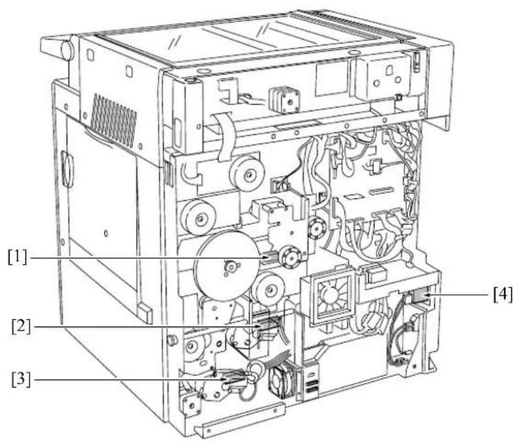
text_image
[1] [2] [3] [4]7322fs4011
[1] TLD (Toner level sensor)
[2] PS9 (Tray set sensor/U)
[3] PS12 (Tray set sensor/L)
3 [4] SW1 (Main power switch)
(2) Bypass tray/Developing unit
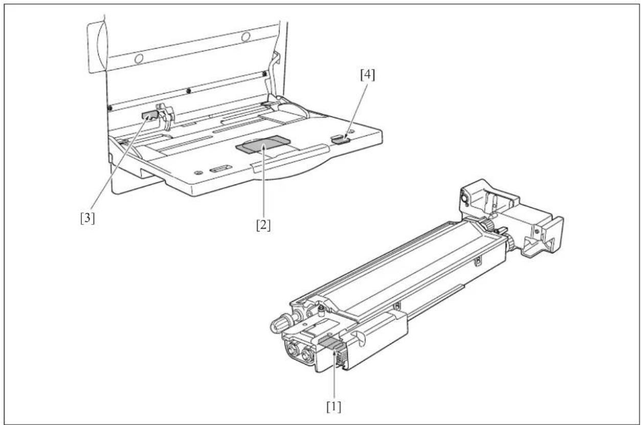
text_image
[1] [2] [3] [4][1] TDS (Toner density sensor)
[3] PS13 (Bypass tray no paper sensor)
[2] VR1 (Bypass tray paper size sensor VR)
[4] PS20 (Bypass tray paper size sensor)
(3) Fixing unit

text_image
[4] [1] [2] [3][1]TH2 (Fixing temperature sensor/2) [3]TS (Thermostat)
[2] TH1 (Fixing temperature sensor/1)
[4] PS2 (Fixing exit sensor)
(4) Scanner section/Operation section

text_image
[1] [2] [3] [4][1] SW2 (Sub power switch)
[3] PS17 (APS sensor)
[2] PS14 (Scanner home position sensor)
[4] PS15 (APS timing sensor)
(5) Main body right side (Paper feed section/ADU)

text_image
[8] [7] [6] [5] [4] [3] [2] [1][1] PS4 (ADU sensor)
[2] PS8 (No paper sensor/U)
[3] PS11 (No paper sensor/L)
[4] PS1 (Registration sensor)
3 [5] PS22 (Timing sensor/L) (7145/7235/7228 only)
[6] PS10 (Upper limit sensor/L)
3 [7] PS21 (Timing sensor/U) (7145/7235/7228 only)
[8] PS7 (Upper limit sensor/U)
(6) Main body front side/Main body left side

text_image
[3] [2] [4] [1][1] SW3 (Interlock switch)
[2] SW1 (Main power switch)
[3] HUM1 (Humidity sensor)
[4] PS5 (Toner bottle sensor)
B. Loads
(1) Main body rear side
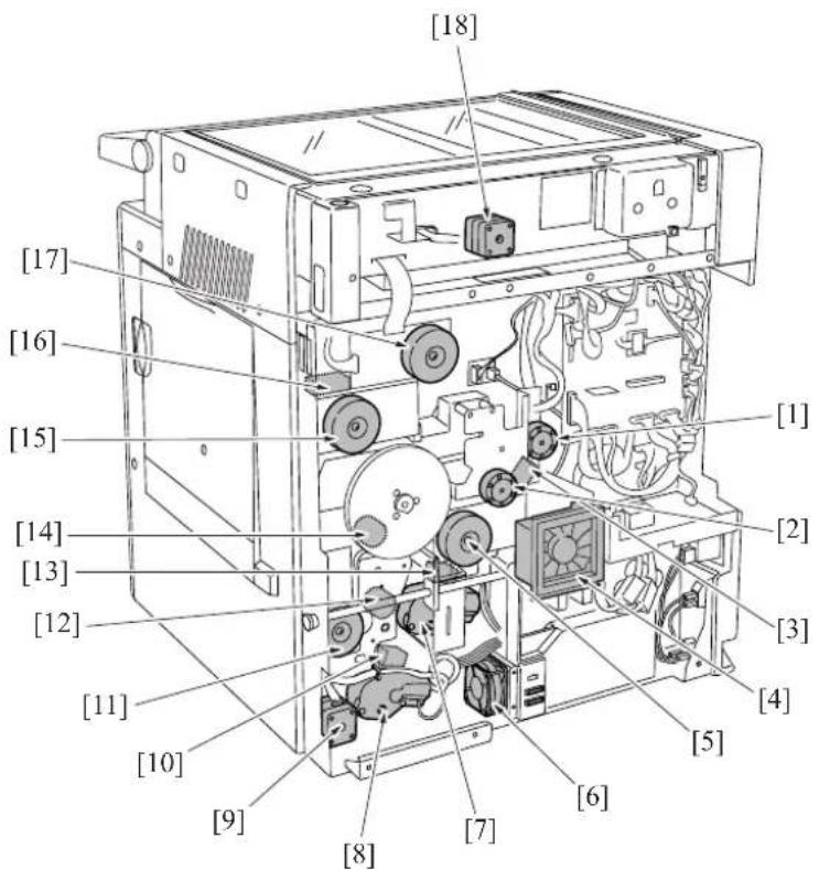
text_image
[18] [17] [16] [15] [14] [13] [12] [11] [10] [9] [8] [7] [6] [5] [4] [3] [2] [1][1] M4 (Toner supply motor 1)
[2] M10 (Toner supply motor 2)
[3] SD9 (Toner solenoid)
[4] FM7 (Internal cooling fan/2) (7145 only)
[5] M3 (Developing motor) (7145 only)
[6] FM1 (DC power supply cooling fan)
[7]M7 (Tray motor/U) [16]SD5 (ADU gate solenoid)
[8] M8 (Tray motor/L)
[9] M6 (ADU motor)
[10] SD2 (1st paper feed solenoid/L)
[11] M9 (Paper feed motor)
[12] MC2 (Loop clutch)
[13] SD1 (1st paper feed solenoid/U)
[14] MC1 (Registration clutch)
[15] M1 (Main motor)
[17] M11 (Fixing motor)
[18] M2 (Scanner motor)
(2) Main body right side (Paper feed section/ADU)

text_image
[5] [/] [1] [2] [4][3]
[1] FM3 (Internal dehumidifying fan/1)
[2] SD4 (Cleaning web solenoid)
[3]SD3 (Bypass feed solenoid)
(3) Write unit
[4] TSL (Transfer synchronization lamp)
[5] FM6 (Internal dehumidifying fan/2)

natural_image
Interior view of an open battery pack with visible internal components and wiring (no text or symbols)[1]
[1]M5 (Polygon motor)
(4) Drum unit/Fixing unit
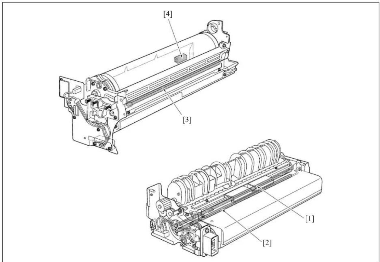
text_image
[4] [3] [1] [2][1] L2 (Fixing heater lamp/1)
[2] L3 (Fixing heater lamp/2)
[3] PCL (Pre-charging exposure lamp)
[4] SD7 (Separation claw solenoid)
(5) Operation section/Scanner section

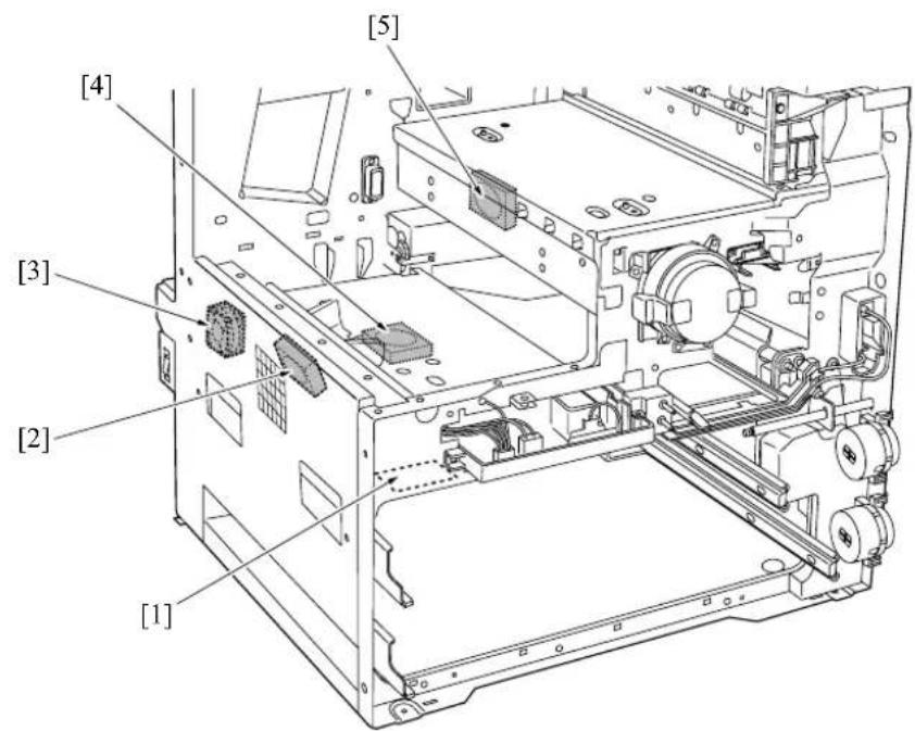
text_image
[1] [2] [3] [4] [5]7322fs4001
[1]PTC (Heater): Option of the service parts setting
[2] FM4 (Internal cooling fan/1)
[3] FM5 (Developing suction fan)
3 [4] FM7 (Polygon cooling fan) (7235 only)
3 [5] FM2 (Fixing cooling fan) (7145/7235 only)
C. PCBs and others
(1) Main body rear side

In the case of the 7145
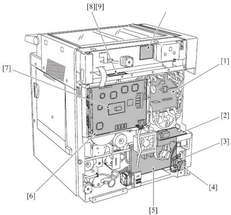
text_image
[8][9] [7] [1] [2] [3] [4] [5] [6][1] CB (Main body control board)
[2] FCB (Fixing control board): only 220V system
[3] CBR2 (Circuit breaker/2)
[4] CBR1 (Circuit breaker/1)
[5]DCPS (DC power supply)
[6] SCB (System control board)
[7] PRMB (Parameter memory board)
[8] INV1 (Exposure lamp inverter)
[9] SCDB (Scanner drive board)


In the case of the 7235/7228/7222
text_image
[8] [7] [9] [1] [2] [3] [4] [5][6][1] CB (Main body control board)
[2] FCB (Fixing control board)
[3] CBR1 (Circuit breaker/1)
[4] CBR2 (Circuit breaker/2)
[5]DCPS (DC power supply)
[6] ADUDB (ADU drive board)
[7] SCB (System control board)
[8] PRMB (Parameter memory board)
[9] INV1 (Exposure lamp inverter)
(2) Operation section/Scanner section
text_image
[1] [2] [3] [4] [5] [6] [7] [8]
[1]TC (Total counter)
(7145 is provided as standard equipment)
[2]KC (Key counter) [7]PSW2B (Power SW2 board)
[3] OB (Operation board)
[4]INV2 (Display inverter)
[5] LCDB (Display board)
[6] PAKB (Panel key board)
[8] L1INVB (Exposure lamp power supply board)
(3) Main body front side
text_image
[3] [1] [2][1] PFDB/U (Paper feed detection board/U)
[2]PFDB/L (Paper feed detection board/L)
[3] HV (High voltage power)
(4) Write unit/Drum unit
text_image
[3] [2] [1][1] TCSB (Toner control sensor board)
[2]INDEX (Index sensor board)
[3] LDB (LD drive board)

1.2 DF-318/320 Parts Layout Drawing
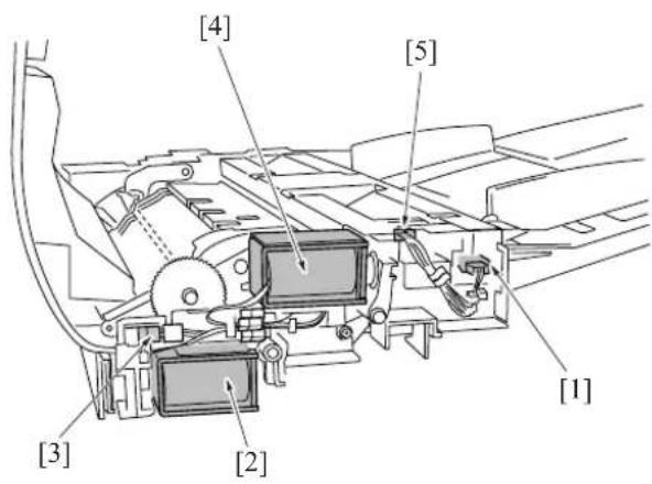
text_image
[4] [5] [1] [3] [2] [2][1] PS301 (Original no paper sensor)
[2] SD301 (Paper exit solenoid)
[3]PS303 (DF open/close sensor)
[4] SD302 (Roller pressure solenoid)
[5] PS304 (Cover open/close sensor)
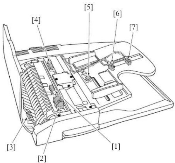
text_image
[4] [5] [6] [7] [3] [2] [1][1] PS308 (Original registration sensor)
[2] SD303 (Stamp solenoid)
[3] PS309 (Original conveyance sensor)
[4]PS302 (Original exit sensor)
[5] VR301 (Original size VR)
[6] PS305 (Original size sensor/1)
[7] PS306 (Original size sensor/2)

text_image
[1] [2] [3] [4] [5][1] M301 (Original feed motor)
[2] M303 (Original reverse motor)
[3]M302 (Original conveyance motor)
[4] FM301 (Cooling fan)
[5] DFDB (DF drive board)
1.3 DB-211 Parts Layout Drawing

text_image
[8] [9] [1] [7] [6] [5] [4] [3] [2][1] PS103 (No paper senso /3)
[2] PS108 (No paper sensor/4)
[3] PS105 (Paper feed sensor/L)
[4] PS107 (Tray upper limit sensor/4)
[5] PSDTB/4 (Paper size detection board/4)
[6] PSDTB/3 (Paper size detection board/3)
[7]HTR100 (Heater): Option of the service parts setting
[8] PS102 (Tray upper limit sensor/3)
[9] PS104 (Paper feed sensor/U)

text_image
[7] [8] [1] [6] [5] [4] [2][3]
[1] PS106 (Tray sensor/4)
[2]DBDB (DB drive board) [6]M100 (DB feed motor)
[3] SD102 (Paper feed solenoid/L)
[4] M102 (Tray up drive motor/4)
[5] M101 (Tray up drive motor/3)
[7] SD101 (Paper feed solenoid/U)
[8] PS101 (Tray sensor/3)
1.4 DB-411 Parts Layout Drawing
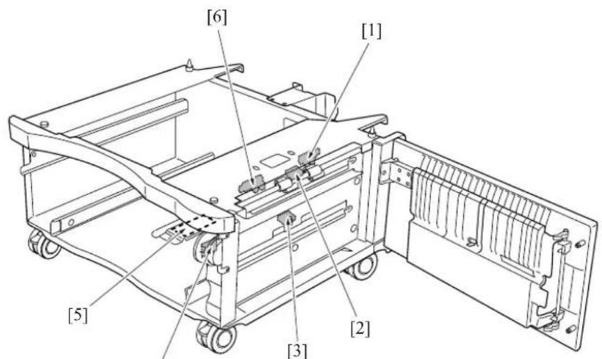
text_image
[1] [2] [3] [5] [6][4]
[1] PS103 (No paper sensor/3)
[2] PS104 (Paper feed sensor/U)
[3] PS105 (Paper feed sensor/L)
[4] PSDTB/3 (Paper size detection board/3)
[5]HTR100 (Heater): Option of the service parts setting
[6]PS102 (Tray upper limit sensor/3)

text_image
[1] [2] [3] [4] [5] [6][1] PS109 (Remaining paper sensor)
[2] PS101 (Tray sensor/3)
[3] M100 (DB feed motor)
[4] M101 (Tray up drive motor/3)
[5] SD101 (Paper feed solenoid/U)
[6] DBDB (DB drive board)
1.5 LT-203 Parts Layout Drawing

text_image
[8] [9][10] [11] [1] [2] [7] [3] [4] [5] [6][1] LTDB (LT drive board)
[2] SW151 (Interlock switch)
[3] PS154 (Remaining paper sensor/1)
[4] PS151 (Remaining paper sensor/2)
[5]HTR150 (Heater): Option of the service parts setting
[6] SD151 (LT paper feed solenoid)
[7] PS153 (No paper sensor)
[8] PS155 (Paper feed sensor)
[9] PS152 (Tray upper limit sensor)
[10] M151 (Tray up drive motor)
[11] M150 (LT paper feed motor)
1.6 FS-112 Parts Layout Drawing
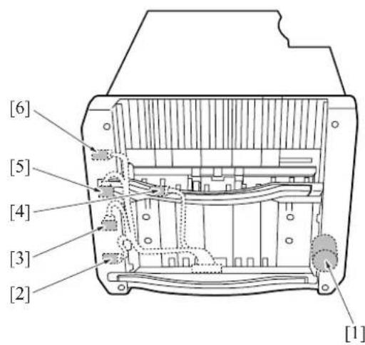
text_image
[6] [5] [4] [3] [2] [1][1] M706 (Tray up/down motor)
[2] PS706 (Tray lower limit sensor)
[3] PS716 (Tray count sensor)
[4] PS703 (Paper exit sensor)
[5] PS704 (Paper exit full sensor)
[6] PS711 (Tray upper limit sensor)

text_image
Technical diagram showing a printer internal structure with labeled parts, including a magnified view of the device's internal components.[1] PS710 (Alignment HP sensor /F)
[4] PS709 (Alignment HP sensor /R)
[2]M704 (Alignment motor /F) [5]PS707 (No paper sensor)
[3]M703 (Alignment motor /R)
text_image
[1] [2][1] PS708 (Stapler unit HP sensor)
[2] M705 (Stapler movement motor)
natural_image
Interior view of an electronic device showing internal circuit board and wiring (no text or symbols visible)[1] MS701 (Front door switch)
[2] FNSCS (FNS control board)
text_image
[5] [4] [3] [2] [1] [6] [7] [8] [9][1] M707 (Paper pressure motor)
[2] MS702 (Shutter switch)
[3]PS705 (Shutter sensor) [8]FM701 (Cooling fan)
[4] PS701 (Paper pressure sensor)
[5]PS702 (FNS entrance sensor)
[6] M702 (Paper exit motor)
[7] M701 (FNS conveyance motor)
[9] SD701 (Roller release solenoid)
text_image
[4] [3] [2] [1][1]M708 (Stapler motor) [3]PS712 (Stapler HP sensor)
[2] PS713 (Staple detection sensor)
[4] PS714 (Stapler ready sensor)
1.7 RU-101 Parts Layout Drawing
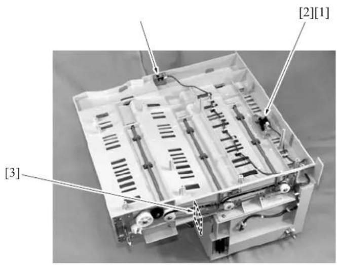
text_image
[2][1] [3][1] PS1 (Front door sensor)
[3] FUB (Fuse board)
[2]PS2 (Paper exit sensor)
1.8 IT-101 Parts Layout Drawing
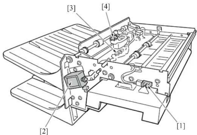
text_image
[3] [4] [2] [1][1] PS25 (IT door sensor)
[3] PS24 (IT paper exit sensor /L)
[2] SD8 (Gate solenoid)
[4] PS23 (IT paper exit sensor /U)
2. CONNECTOR LAYOUT DRAWING
3 2.1 Main Body Connector Layout Drawing
A. Main body control board
In the case of the 7145
flowchart
graph TD
    A["16 (W: 15 pin)"] --> B["17 (W: 36 pin)"]
    C["18 (W: 14 pin)"] --> D["23 (GY: 22 pin)"]
    E["1 (W: 8 pin)"] --> F["38 (W: 9 pin)"]
    G["42 (W: 8 pin)"] --> H["41 (W: 11 pin)"]
    I["24 (W: 40 pin)"] --> J["36 (W: 10 pin)"]
    K["25 (W: 36 pin)"] --> L["27 (W: 8 pin)"]
    M["26 (W: 34 pin)"] --> N["35 (W: 5 pin)"]
    O["19 (W: 9 pin)"] --> P["2 (BK: 68 pin)"]
    Q["40 (W: 4 pin)"] --> R["20 (W: 4 pin)"]
    S["41 (W: 11 pin)"] --> T["21 (W: 6 pin)"]
    U["37 (W: 8 pin)"] --> V["22 (W: 5 pin)"]
    W["38 (W: 9 pin)"] --> X["27 (W: 8 pin)"]

In the case of the 7235/7228/7222

flowchart
graph TD
    A["17 (W: 36 pin)"] --> B["Block"]
    C["28 (W: 22 pin)"] --> D["Block"]
    E["29 (W: 30 pin)"] --> F["Block"]
    G["32 (W: 3 pin)"] --> H["Block"]
    I["19 (W: 3 pin)"] --> J["Block"]
    K["33 (W: 4 pin)"] --> L["Block"]
    M["18 (W: 14 pin)"] --> N["Block"]
    O["90 (W: 8 pin)"] --> P["Block"]
    Q["24 (W: 38 pin)"] --> R["Block"]
    S["15 (W: 30 pin)"] --> T["Block"]
    U["42 (W: 8 pin)"] --> V["Block"]
    W["25 (W: 34 pin)"] --> X["Block"]
    Y["14 (W: 4 pin)"] --> Z["Block"]
    AA["15 (W: 30 pin)"] --> AB["Block"]
    AC["26 (W: 36 pin)"] --> AD["Block"]
    AE["27 (W: 8 pin)"] --> AF["Block"]
    AG["31 (W: 11 pin)"] --> AH["Block"]
    AI["36 (W: 10 pin)"] --> AJ["Block"]
    AK["38 (W: 9 pin)"] --> AL["Block"]
B. System control board

In the case of the 7145

flowchart
graph TD
    A["40 (W: 36 pin)"] --> B["41 (W: 8 pin)"]
    B --> C["39 (W: 9 pin)"]
    C --> D["45 (W: 4 pin)"]
    D --> E["46 (W: 50 pin)"]
    E --> F["34 (W: 24 pin)"]
    F --> G["431 (W: 5 pin)"]
    G --> H["44 (W: 22 pin)"]
    H --> I["432 (W: 24 pin)"]
    I --> J["47 (W: 2 pin)"]
    J --> K["33 (BK: 24 pin)"]
    K --> L["32 (BK: 20 pin)"]
    L --> M["35 (W: 144 pin)"]
    M --> N["501 (BK: 44 pin)"]
    N --> O["42 (W: 9 pin)"]
    O --> P["502 (W: 3 pin)"]
    P --> Q["38 (BK: 100 pin)"]
    Q --> R["500 (W: 4 pin)"]
    R --> S["31 (W: 7 pin)"]
    S --> T["37 (BK: 120 pin)"]
    T --> U["7145fs4033"]

In the case of the 7235/7228/7222
other
| Pin Number | Weight (Pin) | Value | | ---------- | ------------ | ----- | | 46 | 50 | 28 | | 52 | 28 | 28 | | 58 | 20 | 20 | | 59 | 24 | 24 | | 44 | 22 | 22 | | 431 | 5 | 5 | | 502 | 3 | 3 | | 53 | 144 | 144 | | 432 | 12 | 12 | | 40 | 36 | 36 | | 501 | 44 | 44 | | 42 | 9 | 9 | | 41 | 8 | 8 | | 48 | 4 | 4 | | 56 | 100 | 100 | | 55 | 120 | 120 | | 500 | 4 | 4 | | 43 | 6 | 6 | 7322fs4004C. High voltage power
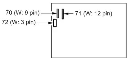
text_image
70 (W: 9 pin) 71 (W: 12 pin) 72 (W: 3 pin)D. DC power supply

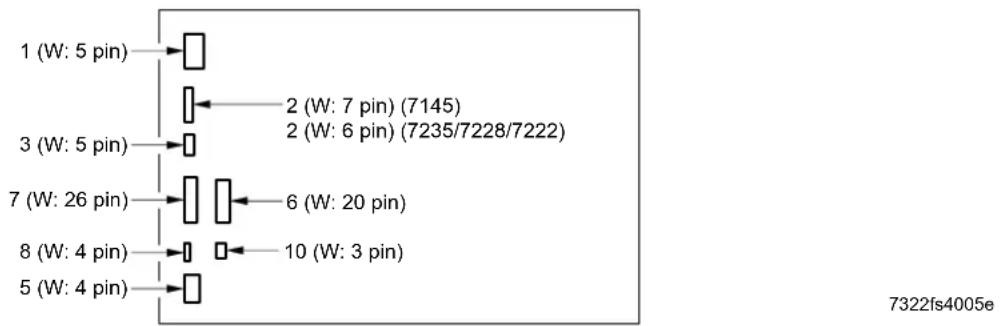
other
| Pin Count | Weight (W) | | --------- | ---------- | | 1 | 5 | | 2 | 7 | | 3 | 5 | | 4 | 4 | | 5 | 4 | | 6 | 20 | | 7 | 26 | | 8 | 4 | | 9 | 3 |E. A/D conversion board
text_image
60 (W: 50 pin)
F. Scanner drive board (7145 only)

text_image
61 (W: 15 pin) 64 (W: 9 pin) 60 (W: 5 pin) 63 (W: 4 pin)62 (W: 3 pin)G. Operation board

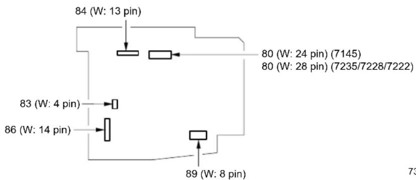
other
| Pin | Power (W) | |---|---| | 80 | 24 | | 80 | 28 | | 83 | 4 | | 84 | 13 | | 86 | 14 | | 89 | 8 | 73H. LD drive board

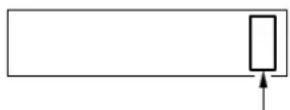
50 (W: 24 pin) (7145)
50 (W: 12 pin) (7235/7228/7222)
7322fs4006e
I. Index sensor board

text_image
51 (W: 5 pin)J. Toner control sensor board
K. Power SW2 board

text_image
1 (W: 8 pin)L. Paper size detection board /U, /L

M. Parameter memory board

N. Exposure lamp power supply board

text_image
97 (W: 2 pin) 96 (W: 2 pin)O. Display inverter

text_image
77 (W: 4 pin) 71 (W: 3 pin)P. Exposure lamp inverter

text_image
931 (W: 4 pin) 930 (W: 3 pin)3 Q. ADU drive board (Except the 7145)
text_image
70 (W: 9 pin)71 (W: 6 pin)7322fs4008
R. Fixing control board (Metric size only)
text_image
99 (W: 4 pin)
2.2 DF-318/320 Connector Layout Drawing
A. DF drive board
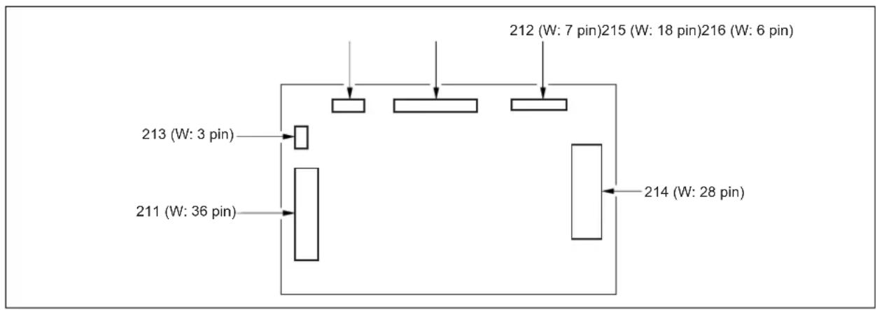
flowchart
graph TD
    A["Block 1"] --> B["Block 2"]
    C["Block 3"] --> D["Block 4"]
    E["Block 5"] --> F["Block 6"]
    G["Block 7"] --> H["Block 8"]
    I["Block 9"] --> J["Block 10"]
    K["Block 11"] --> L["Block 12"]
    M["Block 13"] --> N["Block 14"]
    O["Block 15"] --> P["Block 16"]
    Q["Block 17"] --> R["Block 18"]
    S["Block 19"] --> T["Block 20"]
    U["Block 21"] --> V["Block 22"]
    W["Block 23"] --> X["Block 24"]
    Y["Block 25"] --> Z["Block 26"]
    AA["Block 27"] --> AB["Block 28"]
2.3 DB-211 Connector Layout Drawing
A. DB drive board
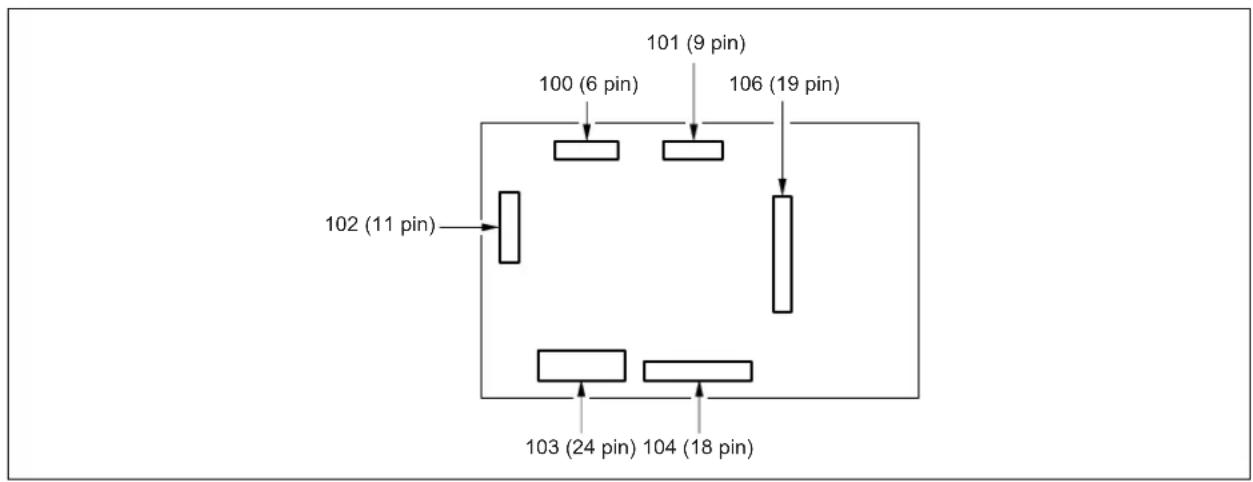
flowchart
graph TD
    A["Block 1"] --> B["Block 2"]
    B --> C["Block 3"]
    C --> D["Block 4"]
    D --> E["Block 5"]
    E --> F["Block 6"]
    F --> G["Block 7"]
    G --> H["Block 8"]
    H --> I["Block 9"]
    I --> J["Block 10"]
    style A fill:#f9f,stroke:#333
    style B fill:#ccf,stroke:#333
    style C fill:#ccf,stroke:#333
    style D fill:#ccf,stroke:#333
    style E fill:#ccf,stroke:#333
    style F fill:#ccf,stroke:#333
    style G fill:#ccf,stroke:#333
    style H fill:#ccf,stroke:#333
    style I fill:#ccf,stroke:#333
    style J fill:#ccf,stroke:#333
B. Paper size detection board /3

text_image
1 (5 pin)C. Paper size detection board /4

text_image
1 (5 pin)2.4 DB-411 Connector Layout Drawing
A. DB drive board
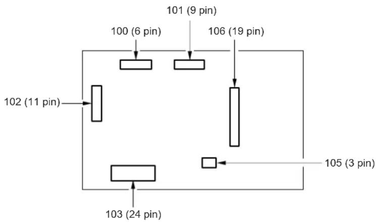
flowchart
graph TD
    A["100 (6 pin)"] --> B["Block"]
    C["101 (9 pin)"] --> D["Block"]
    E["102 (11 pin)"] --> F["Block"]
    G["103 (24 pin)"] --> H["Block"]
    I["106 (19 pin)"] --> J["Block"]
    K["105 (3 pin)"] --> L["Block"]
    B --> M["Horizontal Block"]
    D --> N["Horizontal Block"]
    J --> O["Horizontal Block"]
B. Paper size detection board /3
2.5 LT-203 Connector Layout Drawing
A. LT drive board
text_image
112 (11 pin) 113 (17 pin) 110 (19 pin) 114 (3 pin)2.6 FS-112 Connector Layout Drawing
A. FNS control board
text_image
701 (10 pin) 715 (30 pin) 712(2 pin) 706 (2 pin) 711 (2 pin) 709 (12 pin) 714 (15 pin) 704 (12 pin) 708 (8 pin) 716 (36 pin) 702 (11 pin) FNS CB 703 (12 pin) 713 (3 pin) 710 (2 pin) 705 (W: 6 pin) 717 (2 pin) 707 (30 pin)2.7 RU-101 Connector Layout Drawing
A. Fuse board
text_image
F1 3 (W: 6 pin) 4 (W: 2 pin)- JAM CODE LIST
| Classification | Jam Code | Causes Resulting | operation | Correction | |
| Bypass | J10 | During operation | PS1 (Registration sensor) failed to turn ON within a predetermined time after SD3 (Bypass solenoid) ON. | If copying is in progress at time of jam, the copier completes ejection and then stops. | Take out the paper from the bypass tray, and remove any jammed paper. |
| Upper tray | J11 PS1 | 15 Registration sensor) failed to turn ON within a predetermined time after SD1 (First paper feed solenoid/U) ON. | Open the ADU door, remove any jammed paper. Pull out the tray, and remove any jammed paper. | ||
| Lower tray | J12 PS1 | 1 (Registration sensor) failed to turn ON within a predetermined time after SD2 (First paper feed solenoid/L) ON. | |||
| DB tray | J13 PS1 | 104 (First paper feed sensor/U) failed to turn ON within a predetermined time after SD101 (Paper feed solenoid/U) ON. | Open the DB conveyance door, remove any jammed paperr. Pull out the tray, and remove any jammed paper. | ||
| J14 PS1 | 105 (First paper feed sensor/L) failed to turn ON within a predetermined time after SD102 (Paper feed solenoid/L) ON. | ||||
| LT-203 | J15 PS1 | 5 (Paper feed sensor) failed to turn ON within a predetermined time after SD151 (LT paper feed solenoid) ON. | Open the LT top cover, remove any jammed paper. | ||
| DB tray | J16-1 | The PS1 (Registration sensor) is not turned ON in the specified period of time after either of the PS104 (Paper feed sensor/U), the PS105 (Paper feed sensor/L) and the PS155 (Paper feed sensor) is turned ON and then turned OFF. | Open the ADU door, remove any jammed paper. | ||
| LT-203 | J16-2 PS1 | 104 (Paper feed sensor/U) or PS105 (Paper feed sensor/L) failed to turn ON within a predetermined time after SD151 (LT paper feed solenoid) ON. | Open the LT top cover, remove any jammed paper. | ||
| Others | J20-2 ADU | do door open jamSW3 (Interlock switch) went OFF during copying/printing. | Printer section stops immediately. | Remove jammed paper according to message. | |
| Others FS-112 | J20-3 FNS | front door open jamMS701 (Front door) went OFF during copy-ing/printing or, came off from the main body. | |||
| Others FS-113 | J20-3 FNS | upper front cover open jamPC17 (Front door detection sensor) went OFF during copying/printing or, came off from the main body. | |||
| Others FS-114 | J20-3 FNS | front door open jamThe S1-FN (Front cover open/close detection SW) turned OFF while in copying/print-ing. | |||


| Classification | Jam Code | Causes Resulting | operation | Correction | |
| Others J20-4 | During operation | When an emergency stop instruction is received from the system while in the system emergency stop jam print job. | Printer section stops immediately. | Remove jammed paper according to message. | |
| Others RU-101 | J20-5 R | 101 front door open jamPS1 (Front door sensor) went OFF during copying/printing. | |||
| Others FS-112 | J20-6 FNS | shutter switch operation jamMS702 (Shutter) went ON during copying/printing. | |||
| Others FS-114 | J20-6 Inter | mediate transport guide open jamThe S4-FN (Intermediate jam guide detection SW) turned OFF while in copying/printing. | |||
| Shutter open jamThe S2-FN (Shutter detection SW) turned OFF while in copying/printing. | |||||
| Others FS-113 | J20-7 Top | cover open jamPC18 (Top cover detection sensor) went OFF during copying/printing. | |||
| Others SK-114 | J20-7 SK-1 | 14 open jamThe S4-SK (Saddle safety switch) turned OFF while in copying/printing. | |||
| Others FS-113 | J20-8 Con | necting connector coming off jamThe FS-113 connecting connector comes off from the main body during copying/printing. | |||
| Conveyance | J30 PS1 (Registration sensor) failed to turn ON within a predetermined time after MC1 (Registration clutch) ON. | Open the ADU door, remove any jammed paper. | |||
| J31 PS2 (Fixing exit sensor) failed to turn ON within a predetermined time after MC1 (Registration clutch) ON. | |||||
| Fixing/Exit | J32 The PS2 (Fixing exit sensor) is not turned OFF in the specified period of time (by paper sizes) after it is turned ON. | ||||
| Others J50-1 Failed | to receive print request from system within a predetermined time after PS1 (Registration sensor) ON. | The main body stop immediately. | |||
| J50-2 "Valid" signal failed to turn ON within a predetermined time after start of printing. | |||||
| J50-3 MC1 (Registration clutch) failed to turn ON within a predetermined time after start of printing. | |||||
3
3
3
| Classification | Jam Code | Causes Resulting | operation | Correction | |
| DF-318/320 | J61-1 | During operation | The PS304 (Cover open/close sensor) is turned OFF while in operation. | The RADF stops immediately. | Open the open/ close cover, remove any jammed paper. Remove any jammed paper from the main body's conveyance section. |
| J61-2 | PS303 (DF open/close sensor) is turned OFF while in operation. | ||||
| J62-1 | nal did not feed. | ||||
| J62-2 P | S3 | 09 (Original conveyance sensor) failed to turn ON within a predetermined time after start of refeed for single sided original. | |||
| J62-3 P | S3 | 09 (Original conveyance sensor) failed to turn ON within a predetermined time after start of reverse refeed for double sided original. | |||
| J62-4 P | S3 | 09 (Original conveyance sensor) did not go OFF within the specified period after it went ON, during original exit. | |||
| J62-5 P | S3 | 09 (Original conveyance sensor) did not go OFF within the specified period after it went ON, during original reversal. | |||
| J63-1 P | S3 | 02 (Original exit sensor) did not go ON during original exit. | |||
| J63-2 P | S3 | 02 (Original exit sensor) did not go OFF within the specified period after it went ON, during original exit. | |||
| J63-3 P | S3 | 08 (Original registration sensor) failed to turn OFF within a predetermined time after start of refeed for single sided original. | |||
| J63-4 P | S3 | 09 (Original conveyance sensor) failed to turn OFF within a predetermined time after start of reverse refeed for double sided original. | |||
| J65-1 | When idling | PS308 (Original registration sensor) ON during idling state. | —Open the open/ close cover, remove any jammed paper. | ||
| J65-2 P | S3 | 09 (Original conveyance sensor) ON during idling state. | |||
| J65-3 P | S3 | 08 (Original registration sensor), PS309 (Original conveyance sensor) ON during idling state. | |||
| J65-8 P | S3 | 02 (Original exit sensor) ON during idling state. | |||
| J65-9 P | S3 | 08 (Original registration sensor), PS302 (Original exit sensor) ON during idling state. | |||
| J65-10 | PS309 (Original conveyance sensor), PS302 (Original exit sensor) ON during idling state. | ||||
3
| Classification | Jam Code | Causes Resulting | operation | Correction | ||
| DF-318/320 | J65-11 | When idling | PS308 (Original registration sensor), PS309 (Original conveyance sensor), PS302 (Original exit sensor) ON during idling state. | —Open the open/ | close cover and the reverse guide and remove jammed paper, if any. | |
| FS-112 | J72-1 PS702 | (FNS entrance sensor) ON during idling state. | Remove jammed paper, if any, from the FNS/main body. | |||
| FS-113 | J72-1 The RU-101 | PS2 (Passage sensor) of RU-101 is turned ON while in idling. | Remove jammed paper, if any, from the FNS/RU/main body. | |||
| FS-114 | J72-1 PC4-FN | (Fentrance sensor) is ON during idling. | Remove jammed paper, if any, from the FNS/main body.FS-112 J72-2 | |||
| FS-113 | J72-2 While | state. | Remove jammed paper, if any, from the FNS/main body. | |||
| FS-114 | J72-2 PC5-FN | (Fransport sensor) is ON during idling. | Remove jammed paper, if any, from the FNS/main body. | |||
| J72-3 PC8-FN | (Storage tray detecting sensor) is ON during idling. | |||||
| SK-114 | J72-4 PC20-SK (Saddle exit sensor) is ON during idling. | Remove jam paper from SK/FNS if any. | ||||
| FS-112 | J72-16 During operation | The FNS/main body stop immediately. | Remove jammed paper, if any, from the FNS/main body. | |||
| FS-113 | J72-16 | After the PS2 (Fixing exit sensor) is turned ON, the PS2 (Passage sensor) of RU-101 is not turned ON. | Remove jammed paper, if any, from the FNS/RU/main body. | |||
| FS-114 | J72-16 | PC4-FN (Entrance sensor) does not ON after specified time from PS2 (fixing exit sen-sor) ON. | Open front door and remove jammed paper if any. | |||
| FS-112 | J72-17 | Within a predetermined time after PS702 (FNS entrance sensor) ON. (Straight, sort/ group mode for other than small size) | Remove jammed paper, if any, from the FNS/the main body. | |||
| Classification | Jam Code | Causes Resulting | operation | Correction | |
| FS-113 | J72-17 | During operation | The PS2 (Passage sensor) of RU-101 is not turned OFF.After the PS2 of RU-101 is turned ON, the PC1 (1st tray exit sensor) is not turned ON. (Sort/Group)After the PS2 of RU-101 is turned ON, the PC4 (Upper path sensor) is not turned ON. (Staple)After the PS2 of RU-101 is turned ON, the PC2 (Lower path sensor) is not turned ON. (Staple/Sort/Group)The PC4 is not turned OFF after it is turned ON. (Staple)The PC2 is not turned OFF after it is turned ON. (Staple/Sort/Group)After the PC4 is turned ON, the PC3 (Storage sensor) is not turned ON. (Sta-ple)After the PC2 is turned ON, the PC3 is not turned OFF. (Staple/Sort/Group) | The FNS/main body stop immediately. | Pull out the FNS from the main body, and remove jammed paper, if any, from the FNS/main body. |
| FS-114 | J72-17 | PC4-FN (Entrance sensor) does not OFF after specified time from ON. | Open front door and remove jammed paper if any.PC5-FN(Transpo IV DIAGRAMS | ||
| after specified time from PC4-FN (Entrance sensor) ON. | |||||
| FS-113 | J72-18 | After the PC1 (1st tray exit sensor) is turned ON, it is not turned OFF.After the PC3 (Storage sensor) is turned ON, it is not turned OFF. | Pull out the FNS from the main body, and remove jammed paper, if any, from the FNS/main body. | ||
| FS-114 | J72-18 | PC5-FN (Transport sensor) does not OFF after specified time from ON. | Open front door and remove jammed paper if any. | ||
| FS-112 | J72-19 | PS702 (FNS entrance sensor) failed to turn OFF within a predetermined time after turning ON. (Staple, sort/group) | Remove jammed paper, if any, from the FNS/main body. | ||
| J72-21 | PS707 (No paper sensor) failed to turn OFF within a predetermined time after PS703 (Paper exit sensor) turning ON. (Small size staple, sort/group) | ||||
| FS-113 | J72-21 | During operation | While exiting paper after completion of stapling, the PC5 (Process tray paper detection sensor) is not turned OFF after it is turned ON. | The FNS/main body stop immediately. | Pull out the FNS from the main body, and remove jammed paper, if any, from the FNS/ main body. |
| FS-114SK-114 | J72-21 | After specified time from stapling, PC8-FN (Storage tray paper detect sensor) or PC20-SK (Saddle exit sensor) of SK-114 does not ON. | Remove jammed paper, if any, from the FNS/main body. | ||
| FS-112 | J72-23 | PS707 (No paper sensor) failed to turn OFF within a predetermined time after PS703 (Paper exit sensor) turning ON. (Straight) | |||
| FS-114SK-114 | J72-25 | PC22-SK (Crease roller home position sensor) does not ON within specified time. | Open front door and remove jammed paper if any.FS-114 | ||
| PK-114 | J72-43 | M1-PK (Punch motor) does not OFF after specified time from ON. | |||
| FS-112 | J72-81 | Staple jam M708 (Stapler motor) failed to turn OFF within a predetermined time after turning ON. (Forward operation not completed.) | Remove the jammed staple. | ||
| FS-113 | J72-81 | After the staple motor 1 starts forward rotation, the PC14 (Staple home sensor) is not turned ON in the specified period of time. Then, the staple motor 1 starts backward rotation and the PC14 is turned ON in the specified period of time. | The FNS/main body stop immediately. | Pull out the FNS from the main body, and remove jammed staples, if any. | |
| FS-114 | J72-81 | Staple home position sensor does not ON after specified time from staple motor forward rotation. | Remove jammed staple, if any. | ||
| FS-113 | J72-82 | After the staple motor 2 starts forward rotation, the PC14 (Staple home sensor) is not turned ON in the specified period of time. Then, the staple motor 2 starts backward rotation and the PC14 is turned ON in the specified period of time. | Pull out the FNS from the main body, and remove jammed staples, if any. | ||
| J72-83 | After the staple motors 1 and 2 start forward rotation, the PC14 (Staple home sensor) is not turned ON in the specified period of time. Then, the staple motors 1 and 2 start backward rotation and the PC14 is turned ON in the specified period of time. | ||||
1
| Classification | Jam Code | Causes Resulting | operation | Correction | |
| SK-114 | J72-84 | During operation | Saddle staple home position sensor 1 does not ON within specified time from saddle staple motor 1 forward rotation. | The FNS/main body stop immediately. | Remove jammed staple, if any. |
| J72-85 | Saddle staple home position sensor 2 does not ON within specified time from saddle staple motor 2. | ||||
| IT-101 J | 75-1 | When idling | PS23 (IT exit sensor/U) or PS24 (IT exit sensor /L) went ON during idling. | —Open the | IT cover, remove any jammed paper. |
| J75-10 | During operation | PS23 (IT exit sensor/U) failed to turn ON within a predetermined time after PS2 (Fix-ing exit sensor) turning ON. | Printer section stops immedi-ately. | ||
| J75-11 | PS24 (IT exit sensor/L) failed to turn ON within a predetermined time after PS2 (Fix-ing exit sensor) turning ON. | ||||
| J75-12 | PS2 (Fixing exit) failed to turn OFF within a predetermined time after PS23 (IT exit sen-sor /U) or PS24 (IT exit sensor/L) turning ON. | ||||
| J75-13 | The IT door open jam PS25 (IT door sensor) went OFF during copying/printing. | ||||
| Paper feed | J81 | When idling | PS1 (Registration sensor) ON during idling state. | —Open the | ADU door, remove any jammed paper. |
| J82 PS | 105 | (Paper feed sensor/L) ON during idling state. | Open the DB con-veyance door, remove jammed paper. If paper is jammed in the main body: open the ADU door, remove the jammed paper. | ||
| J83 PS | 155 | (Paper feed sensor) ON during idling state. | Open the LT top cover, remove any jammed paper. | ||
| Paper exit | J90 PS2 | (Fixing exit sensor) ON during idling state. | Open the ADU door, remove any jammed paper. | ||
| ADU conveyance | J92 | During operation | PS1 (Registration sensor) failed to turn ON within a predetermined time after start of ADU reversal. | Printer section stops immediately. | Open the ADU door, remove any jammed paper. |
| J97-1 P | S4 | (ADU sensor) failed to turn ON within a predetermined time after PS2 (Fixing exit sensor) ON. | |||
| J97-2 P | S4 | (ADU sensor) failed to turn OFF within a predetermined time after turning ON. | |||
| J100 | When idling | PS4 (ADU sensor) ON during idling state. — | |||
4. ERROR CODE LIST
4.1 Error Code List

| Classification | Warning code | Causes Resulting | operation | Estimated abnormal parts | |
| Main body | Communication abnormalities | F10-1 | Communication error at CB (Main body control board)Failure in serial communication between the SCB (System control board) and CB (Main body control board). | The main body stops immediately, and the RL1 (Main) turn OFF. | CB (Main body control board)SCB (System control board) |
| F10-2 | Communication error at CB (Main body control board)Serial communication error to the sub CPU in the CB, receiving command error, and platen operation sequence error. | CB (Main body control board) | |||
| F10-3 | Communication error between the CB (Main body control board) and DBDB (DB drive board). | CB (Main body control board)DBDB (DB drive board) | |||
| F10-4 | Sub-CPU A/D conversion errorTwo consecutive failures to respond to CB (Main body control board) A/D conversion request. | CB (Main body control board) | |||
| Paper feed tray abnormalities | F18-1 | Error in main body upper tray upPS10 (Upper limit sensor/L) failed to turn ON within a predetermined time after M7 (Tray motor /U) ON. | CB (Main body control board)M7 (Tray motor/U)PS7 (Upper limit sensor/U) | ||
| F18-2 | Error in main body lower tray upPS10 (Upper limit sensor/L) failed to turn ON within a predetermined time after M8 (Tray motor/L) ON. | CB (Main body control board)M8 (Tray motor/L)PS10 (Upper limit sensor/L) | |||
| F18-3 | Error in DB upper tray upPS102 (Tray upper limit sensor/3) failed to turn ON within a predetermined time after M101 (Tray up drive motor/3) ON. | DBDB (DB drive board)M101 (Tray up drive motor/3)PS102 (Tray upper limit sensor/3) | |||
| Main body | Paper feed tray abnormalities | F18-4 | Error in DB lower tray/LCT tray upPS107 (Tray upper limit sensor/4) failed to turn ON within a predetermined time after M102 (Tray up drive motor/4) ON. | The main body stops immediately, and the RL1 (Main) turn OFF. | DBDB (DB drive board)M102 (Tray up drive motor/4)PS107 (Tray upper limit sensor/4) |
| F18-5 | Error in LT tray upPS152 (Tray upper limit sensor) failed to turn ON within a predetermined time after M151 (Tray up drive motor) ON. | LTDB (LT drive board)M151 (Tray up drive motor)PS152 (Tray upper limit sensor) | |||
| Main body | High voltage power error | F28-1 Charging abnormalityWhen the EM signal (charge_em 1) is detected 5 times at the specified intervals. | If any copying operation is being made, stop the main body after completion of paper exit.Turn the RL1 (Main) off. | Charging coronaHV (High voltage power)CB (Main body control board) | |
| F28-2 Transfer lightning abnormalityWhen the EM signal (trans_em) is detected 3 times at the specified intervals, this phenomenon occurs 5 times in 1 job. | The main body stops immediately, and the RL1 (Main) turn OFF. | Transfer corona sectionHV (High voltage power)CB (Main body control board) | |||
| Classification | Warning code | Causes Resulting | operation | Estimated abnormal parts | |
| F28-3 | Separation lightning abnormalityWhen the EM signal(separate_em) is detected 3 times at the specified intervals, this phenomenon occurs 5 times in 1 job. | The main body stops immediately, and the RL1 (Main) turn OFF. | Separation coronaHV (High voltage power)CB (Main body control board) | ||
| High fixing temperature abnormalities | F34-1 | High fixing temperature abnormality (TH1)The TH1 (Fixing temperature sensor/1) detects a temperature over 457°F continuously for a specified period of time. | The main body stops immediately, and the RL1 (Main) turn OFF. Acceptance of all keys is disabled. | TH1 (Fixing temperature sensor/1)TH2 (Fixing temperature sensor/2)L2 (Fixing heater lamp/1)L3 (Fixing heater lamp/2)CB (Main body control board)DCPS (DC power supply)⚠ WARNING• When F34-* ,*F35- * *or F36- * * (fixing temperature related abnormality) occurs, be sure to repair a defective part before setting the 25 DIPSW 3-1 to 0. If the 25 DIPSW 3-1 is set to 0 without repairing a defective part, this may cause a fire. | |
| F34-2 | High fixing temperature abnormality (TH2)The TH2 (Fixing temperature sensor/2) detects a temperature over 457°F continuously for a specified period of time. | ||||
| Low fixing temperature abnormalities | F35-1 | Low fixing temperature abnormality (L2 burnt out)When turning on electricity to the L2 (Fixing heater lamp/1) for more than the specified period of time while in idling. | |||


| Classification | Warning code | Causes Resulting | operation | Estimated abnormal parts | |
| Main body | Low fixing temperature abnormalities | F35-2 Low | fixing temperature abnormality (L2 burnt out)In other than warming-up, the TH1 (Fixing temperature sensor/1) elapses for more than the specified period of time in a temperature below 329°F (7145)/320°F (except the 7145). | The main body stops immediately, and the RL1 (Main) turn OFF. Acceptance of all keys is disabled. | TH1 (Fixing temperature sensor/1)TH2 (Fixing temperature sensor/2)L2 (Fixing heater lamp/1)L3 (Fixing heater lamp/2)CB (Main body control board)DCPS (DC power supply)⚠ WARNINGWhen F34-* ,*F35- * *or F36- * * (fixing temperature related abnormality) occurs, be sure to repair a defective part before setting the 25 DIPSW 3-1 to 0. If the 25 DIPSW 3-1 is set to 0 without repairing a defective part, this may cause a fire. |
| F35-3 TH | 1 (Fixing temperature sensor/1) low temperature abnormality• In warming up, when the temperature detected by the TH1 at the start of turning on electricity to the L2 (Fixing heater lamp/1) is below 320°F (7145)/302°F (except the 7145), the difference between the TH1 temperature at the time of turning on electricity to the L2 and the TH1 temperature after the elapse of the specified period of time does not reach the specified value.• When the temperature detected by the TH1 at the start of turning on electricity to the L2 is above 320°F (7145)/302°F (except the 7145), the TH1 temperature does not reach the warming-up completion temperature in the specified period of time after the start of turning on electricity to the L2. | ||||
| F35-4 Low | fixing temperature abnormality (L3 burnt out)When turning on electricity to the L3 (Fixing heater lamp/2) for a specified period of time during in idling. | ||||
3
3
3
| Classification | Warning code | Causes Resulting | operation | Estimated abnormal parts | |
| Main body | Low fixing temperature abnormalities | F35-5 Low fixing temperature abnormality (L3 burnt out)In other than warming up, the TH2 (Fixing temperature sensor/2) elapses for more than the specified period of time in a temperature below 329°F (7145)/320°F (except the 7145). | The main body stops immediately, and the RL1 (Main) turn OFF. Acceptance of all keys is disabled. | TH1 (Fixing temperature sensor/1)TH2 (Fixing temperature sensor/2)L2 (Fixing heater lamp/1)L3 (Fixing heater lamp/2)CB (Main body control board)DCPS (DC power supply)⚠ WARNINGWhen F34-*,*F35-* *or F36- * *(fixing temperature related abnormality) occurs, be sure to repair a defective part before setting the 25 DIPSW 3-1 to 0.If the 25 DIPSW 3-1 is set to 0 without repairing a defective part, this may cause a fire. | |
| F35-6 TH2 (Fixing temperature sensor/2) low temperature abnormality• In warming up, when the temperature detected by the TH2 at the start of turning on electricity to the L3 (Fixing heater lamp /2) is below 320°F (7145)/302°F (except the 7145), the difference between the TH2 temperature at the start of turning on electricity to the L3 and the TH2 temperature after the elapse of the specified period of time does not reach the specified value.• When the temperature detected by the TH2 at the start of turning on electricity to the L3 (Fixing heater lamp/2) is above 320°F (7145)/302°F (except the 7145), the TH2 temperature does not reach the warming-up completion temperature in the specified period of time after the start of turning on electricity to the L3. | |||||
| F35-7 Fixing heat roller wrapping jam failure (TH1)While in copying, the TH1 (Fixing temperature sensor/1) detects a condition in which the temperature is lower than the specified one as compared with the temperature taken the specified period of time previously. | |||||

| Classification | Warning code | Causes Resulting | operation | Estimated abnormal parts | |
| Main body | Low fixing temperature abnormalities | F35-8 Fixing heat roller wrapping jam failure (TH2) While in copying, the TH2 (Fixing temperature sensor/2) detects a condition in which the temperature is lower than the specified one as compared with the temperature taken the specified period of time previously. | The main body stops immediately, and the RL1 (Main) turn OFF. Acceptance of all keys is disabled. | TH1 (Fixing temperature sensor/1) TH2 (Fixing temperature sensor/2) L2 (Fixing heater lamp/1) L3 (Fixing heater lamp/2) CB (Main body control board) DCPS (DC power supply) ▲WARNINGWhen F34-*, *F35- * *or F36- * * (fixing temperature related abnormality) occurs, be sure to repair a defective part before setting the 25 DIPSW 3-1 to 0. If the 25 DIPSW 3-1 is set to 0 without repairing a defective part, this may cause a fire. | |
| F35-9 TH1 (Fixing temperature sensor/1) contact failure In warming up, when the temperature detected by the TH2 (Fixing temperature sensor/2) reaches the Ready temperature earlier than the temperature detected by the TH1, the temperature detected by the TH1 does not reach the Ready temperature in the specified period of time after the temperature detected by the TH2 reaches the Ready temperature. | |||||
| F35-10 TH2 (Fixing temperature sensor/2) contact failure In warming up, when the temperature detected by the TH1 (Fixing temperature sensor/1) reaches the Ready temperature earlier than the temperature detected by the TH2, the temperature detected by the TH2 does not reach the Ready temperature in the specified period of time after the temperature detected by the TH1 reaches the Ready temperature. | |||||
| Sub CPU fixing sensor abnormalities | F36-1 TH1 (Fixing temperature sensor/1) high temperature abnormality (Sub CPU detection) In the sub CPU, the TH1 detects a temperature above 457°F for the specified period of time. | ||||

| Classification | Warning code | Causes Resulting | operation | Estimated abnormal parts | |
| Main body | Sub CPU fixing sensor abnormalities | F36-2 TH1 (Fixing temperature sensor/1)open abnormality(Sub CPU detection)In the sub CPU, the TH1 detects a temperature from 18°F to -4°F continuously for the specified period of time. | The main body stops immediately, and the RL1 (Main) turn OFF. Acceptance of all keys is disabled. | TH1 (Fixing temperature sensor/1)TH2 (Fixing temperature sensor/2)L2 (Fixing heater lamp/1)L3 (Fixing heater lamp/2)CB (Main body control board)DCPS (DC power supply)⚠ WARNINGWhen F34-* ,* F35- * * or F36- * * (fixing temperature related abnormality) occurs, be sure to repair a defective part before setting the 25 DIPSW 3-1 to 0.If the 25 DIPSW 3-1 is set to 0 without repairing a defective part, this may cause a fire. | |
| F36-3 TH2 (Fixing temperature sensor/2) high temperature abnormality(Sub CPU detection)In the sub CPU, the TH2 detects a temperature above 457°F for the specified period of time. | |||||
| F36-4 TH2 (Fixing temperature sensor/2) open abnormality(Sub CPU detection)In the sub CPU, the TH2 detects a temperature from 18°F to -4°F continuously for the specified period of time. | |||||
| Scanner abnormalities | F41-1 M2 (Scanner motor) drive abnormalityOccurs at exposure unit initial search or at return scan if PS14 (Scanner home position sensor) fails to turn ON within a predetermined time. | Scanner stops immediately. | M2 (Scanner motor)SCDB (Scanner drive board)(7145 only)CB (Main body control board) | ||
| F43-1 L1 (Exposure lamp) abnormalityAfter the L1 is turned ON, an L1 abnormality signal is detected continuously after the elapse of the specified period of time. | L1 (Exposure lamp) | ||||
| Image control abnormalities | F46-1 Laser driver abnormality Caused by overcurrent in laser output. | The main body stops immediately, and the RL1 (Main) turn OFF. | Laser diodeLDB (LD drive board) | ||
| F46-8 Laser index abnormalityOccurs if index period is different from expected value. | INDEX (Index sensor board)M5 (Polygon motor)SCB (System control board)Laser route | ||||
| F46-10 AOC abnormalityAOC counter overflow | Scanner stops immediately. | ADB (A/D conversion board)L1 (Exposure lamp)INV1 (Exposure lamp inverter)SCB (System control board)Exposure unit stop position | |||
| F46-11 AGC abnormalityAGC counter overflow | |||||
| Main body | Image control abnormalities | F49-4 IN | DEX (Index sensor board) connection abnormality | The main body stops immediately, and the RL1 (Main) turn OFF. | INDEX (Index sensor board)SCB (System control board) |
| F49-6 ADB (A/D conversion board) connection abnormality | Scanner stops immediately. | CCD on ADB (A/D conversion board)SCB (System control board)Flex wiring harness | |||
| Motor speed abnormalities | F51-2 M | 11 (Fixing motor) speed abnormalityMotor lock detection (LOCK) signal has been detected 5 times at the specified intervals. | The main body stops immediately, and the RL1 (Main) turn OFF. | M11 (Fixing motor)CB (Main body control board) | |
| F51-4 (7145) | M3 (Developing motor) speed abnormalityMotor lock detection (LD) signal has been detected 5 times at the specified intervals. | M3 (Developing motor)CB (Main body control board) | |||
| F51-5 (7145) | M1 (Main motor) speed abnormalityMotor lock detection (LOCK) signal has been detected 5 times at the specified intervals. | M1 (Main motor)CB (Main body control board) | |||
| F51-6 M | 5 (Polygon motor) speed abnormalityM5 was not locked 7 sec. after starting to run. | M5 (Polygon motor)CB (Main body control board) | |||
| Fan lock abnormalities | F52-1 FM | 3 (Internal dehumidifying fan) abnormalityWhen the motor lock signal (EM) was detected at the specified cycle with [H] detected continuously, the fan has been judged abnormal in the succeeding two retries. | FM3 (Internal dehumidifying fan/1)CB (Main body control board) | ||
3
| Classification | Warning code | Causes Resulting | operation | Estimated abnormal parts | |
| Main body | Fan lock abnormalities | F52-2(7145/7235) | FM2 (Fixing cooling fan/1) abnormalityWhen the motor lock signal (LOCK) was detected at the specified cycle with [H] detected continuously, the cooler has been judged abnormal at the succeeding two retries. | The main body stops immediately, and the RL1 (Main) turn OFF. | FM2 (Fixing cooling fan)CB (Main body control board) |
| F52-3 FM4 (Internal cooling) abnormalityWhen the motor lock signal (EM) was detected at the specified cycle with [H] detected continuously, the fan has been judged abnormal at the succeeding two retries. | FM4 (Internal cooling fan/1)CB (Main body control board) | ||||
| F52-4 FM5 (Developing suction fan) abnormalityWhen the motor lock signal (EM) was detected at the specified cycle with [H] detected continuously, the fan has been judged abnormal at the succeeding two retries. | FM5 (Developing suction fan)CB (Main body control board) | ||||
| F52-5 FM6 (Internal dehumidifying fan/2) abnormalityWhen the motor lock signal (EM) was detected at the specified cycle with [H] detected continuously, the fan has been judged abnormal at the succeeding two retries. | FM6 (Internal dehumidifying fan/2)CB (Main body control board) | ||||
| F52-6 Printer controller cooling fan abnormalityWhen an error status signal was sent from the printer controller. | Printer controller | ||||
| F52-7 FM301 (Cooling fan) abnormalityWhen the motor lock signal (EM) was detected at the specified cycle with [H] detected continuously, the fan has been judged abnormal at the succeeding two retries. | FM301 (Cooling fan)CB (Main body control board) | ||||


| Classification | Warning code | Causes Resulting | operation | Estimated abnormal parts | |
| Main body | Fan lock abnormalities | F52-8 (7145) | FM7 (Internal cooling fan/2) abnormalityWhen the motor lock signal (EM) was detected at the specified cycle with [H] detected continuously, the fan has been judged abnormal at the two succeeding retries. | The main body stops immediately, and the RL1 (Main) turn OFF. | FM7 (Internal cooling fan/2) CB (Main body control board) |
| F52-9 HD-103 cooling fan abnormalityWhen a lock signal was detected while in the HDD operation. | HD-103 Cooling fan SCB (System control board) | ||||
| F52-10 (7235) | FM7 Polygon cooling fan abnormalityWhen motor lock signal (EM) was detected at the specified cycle with [H] also detected continuously, the fan was judged to be abnormal after being twice retried. | FM7 (Polygon cooling fan) CB (Main body control board) | |||
| Image control communication abnormalities | E56-1 Communication abnormality between system-control of the SCB (System control board) and engine-control of the CB (Main body control board).Occurs if SCB fails to responds when SW2 (Sub power switch) turns ON. | Engine power supply OFF | SCB (System control board) CB (Main body control board) | ||
| E56-2 Communication abnormality between system-control of the SCB (System control board) and engine-control of the CB (Main body control board). While on standby, the process Ready signal has not been detected for the specified period of time. | |||||
| E56-3 Communication abnormality between system-control of the SCB (System control board) and engine-control of the CB (Main body control board). While on standby, the scanner Ready signal has not been detected for the specified period of time. | |||||
| Main body | Image control communication abnormalities | E56-4 C | Communication abnormality between system-control of the SCB (System control board) and engine-control of the CB (Main body control board). While on standby, the FNS Ready signal has not been detected for the specified period of time. | Engine power supply OFF | SCB (System control board)FNSCB (FNS control board)CB (Main body control board) |
| E56-5 C | Communication abnormality between system-control of the SCB (System control board) and engine-control of the CB (Main body control board). Platen-original size notification timeout. | SCB (System control board)CB (Main body control board) | |||
| Operations unit control abnormalities | E56-6 O | Operation status errorMemory access error at copy insertion. | SCB (System control board) | ||
| E56-7 O | Operation management errorControl error at panel manager | ||||
| E56-8 O | Operation drawing error 1Screen-data drawing mismatch | ||||
| E56-9 O | Operation drawing error 2Drawing-component data error | ||||
| E56-10 O | Operation panel communication abnormalityCommunication error with the operating section CPU | SCB (System control board)OB (Operation board) | |||
| Image control communication abnormalities | E56-11(Except the 7145) | Machine type judgement abnormalityThe type information of the SCB (System control board) is different from the type information of the CB (Main body control board). | SCB program | ||
| E56-12 | Communication abnormality between system-control of the SCB (System control board) and engine-control of the CB (Main body control board). There is no response from the engine after a signal is sent for periodic communication. | SCB (System control board)CB (Main body control board) | |||
3
| Classification | Warning code | Causes Resulting | operation | Estimated abnormal parts | |
| Main body | Image control communication abnormalities | E56-13 | Communication abnormality between system-control of the SCB (System control board) and engine-control of the CB (Main body control board). The destination value RAM area on the engine side is unjustly rewritten. | Engine power supply OFF | SCB (System control board)CB (Main body control board) |
| FNS | FNS communication abnormalities (FS-112/113/114) | F70-1 FNS | Communication abnormalityFailure in serial communication between the CB (Main body control board) and FNSCB (FNS control board). | The main body stops immediately, and the RL1 (Main) turn OFF. | CB (Main body control board)FNSCB (FNS control board) |
| FS-112 | F70-11 FS | -112 flash-ROM abnormalityDetected checksum error in FNS flash ROM. | FNSCB (FNS control board) | ||
| FS-113 | F77-1 M8 | (Shift motor) drive abnormalityWhen starting to return to the home position, the PC10 (Shift home sensor) is not turned ON in the specified period of time after the M8 is turned ON.When starting to move to the shift position, the PC10 is not turned OFF in the specified period of time after the M8 is turned ON. | M8 (Shift motor)PC10 (Shift home sensor)PC11 (Shift motor pulse sensor)PWB-A (Control board) | ||
| FS-112 F | F77-2 • The | PS711 (Tray upper limit sensor) is not turned ON in the specified period of time after the paper extractor starts to go up.While in copying, the PS711 is not turned ON in the specified period of time after the M706 starts to go up.Paper is not detected even after the paper detection operation is made 3 times. | M706 (Tray up drive motor)FNSCB (FNS control board)PS711 (Tray upper limit sensor)PS706 (Tray lower limit sensor) | ||

| Classification | Warning code | Causes Resulting | operation | Estimated abnormal parts | |
| FNS | FS-113 F | 77-2 M7 | (Elevator motor) drive abnormalityWhile the elevate tray is going up, the PWB-F (Elevate tray top face sensor) is not turned OFF in the specified period of time after the M7 is turned ON.While the elevate tray is going down, the M7 is locked.The S2 (Elevate tray upper limit switch) or the S3 (Elevate tray lower limit switch) is turned ON in the specified period of time after the elevate tray starts to drive. | The main body stops immediately, and the RL1 (Main) turn OFF. | M7 (Elevator motor)PWB-A (Control board)PWB-F (Elevate tray top face sensor)S2 (Elevate tray upper limit switch)S3 (Elevate tray lower limit switch) |
| FS-114 F | 77-2 M11 | -FN (Elevator motor) drive failureDuring tray ascending, PC14-FN (Top face detection sensor) does not ON after specified time from M11-FN ON.During tray descending, it does not reach the target position within specified time.During tray descending, M11-FN is locked. | M11-FN (Elevator motor)PWB-A FN (Control board)PC15-FN (Top face detection sensor) | ||
| FS-112 F | 77-3 M70 | (Alignment motor /F) drive abnormalityThe PS710 (Alignment HP sensor/F) cannot be attained in the specified period of time after the start of the alignment plate HP search.The PS710 cannot be passed through in the specified period of time after the alignment plate starts to move to the size position. | M704 (Alignment motor/F)PS710 (Alignment plate HP sensor/F)FNSCB (FNS control board)Sensor wiring harness/2Motor wiring harness/2 | ||
| FNS | FS-113 | F77-3 M5 | (Alignment motor) drive abnormalityWhile in search of the home position, the PC9 (Alignment home sensor) is not turned ON in the specified period of time after the M5 is turned ON.When the alignment operation starts, the PC9 is not turned OFF in the specified period of time after the M5 is turned ON. | The main body stops immediately, and the RL1 (Main) turn OFF. | M5 (Alignment motor)PWB-A (Control board)PC9 (Alignment home sensor) |
| FS-114 | F77-3 M4 | FN (Alignment motor 1) driving failurePC6-FN (Alignment home position sensor 1) does not ON within specified time from start of alignment plate HP searching.PC6-FN does not OFF within specified time from start of alignment plate home position search. | M4-FN (Alignment motor 1)PWB-A FN (Control board)PC6-FN (Alignment home position sensor 1) | ||
| FS-113 | F77-4 M13 | (Paper exit roller separation motor) drive abnormalityWhen the pressure position drive starts, the PC13 (Paper exit roller home sensor) is not turned ON in the specified period of time after the M13 is turned ON.When the separation position drive starts, the PC13 is not turned OFF in the specified period of time after the M13 is turned ON. | M13 (Paper exit roller separation motor)PWB-A (Control board)PC13 (Paper exit roller home sensor) | ||
1
| Classification | Warning code | Causes Resulting | operation | Estimated abnormal parts | |
| FNS | FS-114 F | 77-4 M6- | FN (Exit open/close motor) drive failureAfter starting pressing position driving, PC12-FN (Exit roller home position sensor) does not ON within specified time from M6-FN ON.After starting separation position driving, PC12-FN does not OFF within specified time from M6-FN ON. | The main body stops immediately, and the RL1 (Main) turn OFF. | PWB-A FN (Control board)M6-FN (Exit open/close motor)PC12-FN (Exit roller home position sensor) |
| FS-112 F | 77-5 M70 | 7 (Paper pressure motor) drive abnormalityThe M707 does not make a turn in the specified period of time after it starts to operate. | M707 (Paper pressure motor)FNSCB (FNS control board)Sensor wiring harness/1 | ||
| FS-113 F | 77-5 M12 | (Storage roller separation motor) drive abnormalityWhen the pressure position drive starts, the PC12 (Storage roller home sensor) is not tuned on in the specified period of time after the M12 is turned ON.When the separation position drive starts, the PC12 is not turned ON in the specified period of time after the M12 is turned ON. | M12 (Storage roller separation motor)PWB-A (Control board)PC12 (Storage roller home sensor) | ||
| FS-112 F | 77-6 M70 | 5 (Stapler movement motor) abnormalityThe PS708 (Stapler unit HP sensor) is not turned ON in the specified period of time after the start of the home position search.The PS708 is not turned OFF in the specified period of time after the start of the movement to the 2-staple standby position. | FNSCB (FNS control board)M705 (Stapler movement motor)PS708 (Stapler unit HP sensor)Sensor wiring harness/2Motor wiring harness/1 | ||
| FNS | FS-113 | F77-6 M6 | (Staple movement motor) drive abnormalityThe PC14 (Staple home sensor) is not turned ON in the specified period of time after the M13 is turned ON.The home position cannot be passed through in the specified period of time after the start of the movement to the 1-staple position. | The main body stops immediately, and the RL1 (Main) turn OFF. | PWB-A (Control board)M6 (Staple movement motor)PC14 (Staple home sensor) |
| FS-114 | F77-6 M7 | FN (Stapling unit moving motor) driving failurePC10-FN (Staple home position sensor) does not ON within specified time from starting of HP search.PC10-FN does not OFF when starting to move to 1-position stapling position. | M7-FN (Stapling unit moving motor)PWB-A FN (Control board)PC10-FN (Staple home position sensor) | ||
| FS-112 | F77-11 Stapler reversal abnormalityThe PS712 (Stapler HP sensor) cannot be attained in the specified period of time after the start of the reverse rotation of the M708 (Staple motor). | FNSCB (FNS control board)M708 (Staple motor)PS712 (Stapler HP sensor) | |||
| FS-113 | F77-11 Stapler /F drive abnormalityThe home position cannot be passed through in the specified period of time after the start of the staple 2/F drive.While in the staple 2/F drive, the home position cannot be attained in the specified period of time after the home position is turned OFF.The home position cannot be attained in the specified period of time after the start of the reverse drive of the staple 2/F. | PWB-A (Control board)Staple motor 2 | |||
→
| Classification | Warning code | Causes Resulting | operation | Estimated abnormal parts | |
| FSF | FS-113 F | 77-12 Stapler /R drive abnormalityThe home position cannot be passed through in the specified period of time after the start of the staple1/R drive.While in the staple1/F drive, the home position cannot be attained in the specified period of time after the home position is turned OFF.The home position cannot be attained in the specified period of time after the start of the reverse drive of the staple1/F. | The main body stops immediately, and the RL1 (Main) turn OFF. | PWB-A (Control board)Staple motor 1 | |
| FS-114 F | 77-12 Stapler drive failureStaple motor does not move from home position within specified time from start of staple driving.Staple motor does not reach the home position within specified time from start of staple reverse driving. | PWB-A FN (Control board)Staple motor | |||
| F77-13 Saddle staple 1 drive failureDuring driving of saddle staple motor 1, saddle staple does not move from home position within specified time.During reverse driving of saddle staple motor 1, it does not reach the home position within specified time. | PWB-C SK (Control board)Saddle staple motor 1 | ||||
| F77-14 Saddle staple 2 drive failureDuring saddle staple motor 2 driving, it does not move from home position.During reverse driving of saddle staple motor 2, it does not reach the home position within specified time. | PWB-C SK (Control board)Saddle staple motor 2 | ||||
| FS | FS-112 F77-16 M703 (Alignment motor/R) abnormalityThe PS709 (Alignment HP sensor/R) cannot be attained in the specified period of time after the start of the alignment plate HP search.The PS709 cannot be passed through in the specified period of time after the alignment plate starts to move to the size position. | The main body stops immediately, and the RL1 (Main) turn OFF. | M703 (Alignment motor/R)PS709 (Alignment HP sensor/R)FNSCB (FNS control board)Sensor wiring harness/2Motor wiring harness/1 | ||
| FM701 (Cooling fan)FNSCB (FNS control board)Motor wiring harness/2 | |||||
| PWB-C SK (Control board)M13-SK (In & out guide motor)PC23-SK (In & out guide home position sensor) | |||||
| PWB-C SK (Control board)M14-SK (Layable guide motor)PC26-SK (Layable guide home position sensor) | |||||
1
| Classification | Warning code | Causes Resulting | operation | Estimated abnormal parts | |
| FSF | FS-114 F | 77-24 Saddle exit roller drive failurePC18-SK (Saddle exit open/ close motor) does not ON within specified time from press-operation starting of M9-SK (Saddle exit open/ close motor).PC18-SK does not OFF within specified time from M9-SK separation operation starting. | The main body stops immediately, and the RL1 (Main) turn OFF. | PWB-C SK (Control board)M9-SK (Saddle exit open/ close motor)PC18-SK (Saddle exit roller home position sensor) | |
| F77-25 M10-SK (Crease motor) drive failureDuring M10-SK driving, PC22-SK (Crease roller home position sensor) does not ON within specified time. | PWB-C SK (Control board)M10-SK (Crease motor)PC22-SK (Crease roller home position sensor) | ||||
| F77-26 M8-SK (Saddle exit motor) drive failureLock signal ON is continuously detected for the specified period within specified time from M8-SK drive start.Lock signal OFF is continuously detected for the specified period within specified time from stopping of M8-SK drive signal. | PWB-C SK (Control board)M8-SK (Saddle exit motor) | ||||
| F77-27 Shutter drive failureDuring M6-FN (Exit open/ close motor) driving (closing shutter), PC16-FN (Shutter home position sensor) does not ON within specified time.During M6-FN driving (opening shutter) PC16-FN does not OFF within specified time. | 6-FN (Exit open/close motor)PWB-A FN (Control board)PC16-FN (Shutter home position sensor) | ||||
| FNS | FS-114 F | 77-28 M5 | FN (Alignment motor 2) driving failurePC7-FN (Alignment home position sensor 2) does not ON within specified time from starting of alignment plate home position search.PC7-FN does not OFF within specified time from starting of alignment plate HP search. | The main body stops immediately, and the RL1 (Main) turn OFF. | M5-FN (Alignment motor 2)PWB-A FN (Control board)PC7-FN (Alignment home position sensor 2) |
| F77-29 SL2-FN (Exit paddle solenoid) driving failurePC11-FN (Exit paddle home position sensor) does not ON within specified time from SL2-FN ON (paddle move aside).PC11-FN does not OFF within specified time from SL2-FN ON (during pressing paper). | L2-FN (Exit paddle solenoid)PWB-A FN (Control board)PC11-FN (Exit paddle home position sensor) | ||||
| FS-113 F | 77-53 | M11 (Punch motor) drive abnormality The PC15 (Punch motor pulse sensor) does not turn OFF the specified period of time after the M11 turns on. | M11 (Punch motor)PC15 (Punch motor pulse sensor) | ||
| F77-54 M14 (Punch movement motor) drive abnormality (inch system only)When starting the punch 2-hole position switch drive, the S4 (punch hole position switch) is not turned ON in the specified period of time after the M14 is turned ON.When starting the punch 3-hole position switch drive, the S4 is not turned OFF in the specified period of time after the M14 is turned ON. | PWB-A FN (Control board)Punch motorPunch position sensor 1Punch position sensor 2 | ||||
| FS-114 F | 77-55 Punch motor drive failureDuring driving punch motor,punch position sensor 1,2 do not OFF within specified time. | PWB-A (Control board)M14 (Punch movement motor)S4 (Punch hole position switch) | |||
3
| Main body | HDD | ||||||||||||||||||||||||||||||||||||||||||||||||||||||||||||||||||||||||||||||||||||||||||||||||||||||||||||||||||||||||||||||||||||||||||||||||||||||||||||||||||||||||||||||||||||||||||||||||||||||||||||||||||||||||||||||||||||||||||||||
| Main body | |||||||||||||||||||||||||||||||||||||||||||||||||||||||||||||||||||||||||||||||||||||||||||||||||||||||||||||||||||||||||||||||||||||||||||||||||||||||||||||||||||||||||||||||||||||||||||||||||||||||||||||||||||||||||||||||||||||||||||||||
| Main body | |||||||||||||||||||||||||||||||||||||||||||||||||||||||||||||||||||||||||||||||||||||||||||||||||||||||||||||||||||||||||||||||||||||||||||||||||||||||||||||||||||||||||||||||||||||||||||||||||||||||||||||||||||||||||||||||||||||||||||||||
| Main body | Main body | ||||||||||||||||||||||||||||||||||||||||||||||||||||||||||||||||||||||||||||||||||||||||||||||||||||||||||||||||||||||||||||||||||||||||||||||||||||||||||||||||||||||||||||||||||||||||||||||||||||||||||||||||||||||||||||||||||||||||||||||
| Main body | Nonvolatile memory abnormalities | F80-1 Nonvolatile memory abnormality*1 | |||||||||||||||||||||||||||||||||||||||||||||||||||||||||||||||||||||||||||||||||||||||||||||||||||||||||||||||||||||||||||||||||||||||||||||||||||||||||||||||||||||||||||||||||||||||||||||||||||||||||||||||||||||||||||||||||||||||||||||
| F80-2 Nonvolatile memory abnormality*1 | |||||||||||||||||||||||||||||||||||||||||||||||||||||||||||||||||||||||||||||||||||||||||||||||||||||||||||||||||||||||||||||||||||||||||||||||||||||||||||||||||||||||||||||||||||||||||||||||||||||||||||||||||||||||||||||||||||||||||||||||
| F80-3 Nonvolatile memory abnormality*1 | |||||||||||||||||||||||||||||||||||||||||||||||||||||||||||||||||||||||||||||||||||||||||||||||||||||||||||||||||||||||||||||||||||||||||||||||||||||||||||||||||||||||||||||||||||||||||||||||||||||||||||||||||||||||||||||||||||||||||||||||
| F80-4 Nonvolatile memory abnormality*1 | |||||||||||||||||||||||||||||||||||||||||||||||||||||||||||||||||||||||||||||||||||||||||||||||||||||||||||||||||||||||||||||||||||||||||||||||||||||||||||||||||||||||||||||||||||||||||||||||||||||||||||||||||||||||||||||||||||||||||||||||
| F80-5 Nonvolatile memory abnormality*1 | |||||||||||||||||||||||||||||||||||||||||||||||||||||||||||||||||||||||||||||||||||||||||||||||||||||||||||||||||||||||||||||||||||||||||||||||||||||||||||||||||||||||||||||||||||||||||||||||||||||||||||||||||||||||||||||||||||||||||||||||
| Flash ROM abnormalities | F81-1 Flash ROM abnormality Detected checksum error in SCB (System control board)'s FlashROM. | SCB (System control board) | |||||||||||||||||||||||||||||||||||||||||||||||||||||||||||||||||||||||||||||||||||||||||||||||||||||||||||||||||||||||||||||||||||||||||||||||||||||||||||||||||||||||||||||||||||||||||||||||||||||||||||||||||||||||||||||||||||||||||||||
| F81-2 Software abnormality CB (Main body control board) and SCB (System control board) have non-matching software device types. | SCB program SCB program | ||||||||||||||||||||||||||||||||||||||||||||||||||||||||||||||||||||||||||||||||||||||||||||||||||||||||||||||||||||||||||||||||||||||||||||||||||||||||||||||||||||||||||||||||||||||||||||||||||||||||||||||||||||||||||||||||||||||||||||||
| OS error | F81-4 An OS error occurs in the image control unit in the SCB (System control board). | SCB (System control board) | |||||||||||||||||||||||||||||||||||||||||||||||||||||||||||||||||||||||||||||||||||||||||||||||||||||||||||||||||||||||||||||||||||||||||||||||||||||||||||||||||||||||||||||||||||||||||||||||||||||||||||||||||||||||||||||||||||||||||||||
| HDD initialization abnormality | F82-1 A physical abnormality occurs in the HDD and a checksum abnormality in the DRAM occur. | SCB (System control board) HDD (Hard disk) Reformatting of the HDD | |||||||||||||||||||||||||||||||||||||||||||||||||||||||||||||||||||||||||||||||||||||||||||||||||||||||||||||||||||||||||||||||||||||||||||||||||||||||||||||||||||||||||||||||||||||||||||||||||||||||||||||||||||||||||||||||||||||||||||||
| HDD abnormalities | F82-2 Document manager initialization abnormality | ||||||||||||||||||||||||||||||||||||||||||||||||||||||||||||||||||||||||||||||||||||||||||||||||||||||||||||||||||||||||||||||||||||||||||||||||||||||||||||||||||||||||||||||||||||||||||||||||||||||||||||||||||||||||||||||||||||||||||||||
| HDD error | F82-3 I-FAX report initializing error HDD (Hard disk) | SCB (System control board) | |||||||||||||||||||||||||||||||||||||||||||||||||||||||||||||||||||||||||||||||||||||||||||||||||||||||||||||||||||||||||||||||||||||||||||||||||||||||||||||||||||||||||||||||||||||||||||||||||||||||||||||||||||||||||||||||||||||||||||||
| Access abnormalities | E82-10 Document manager access abnormality (overall) The count of E82-11 to E82-17 is an overall count for E82-10. Abnormality VxWorks error | E82-12 Document manager access abnormality Job control access error | E82-11 Document manager access abnormality VxWorks error | E82-13 Document manager access abnormality Image conversion job access error | E82-12 Document manager access abnormality Job control access error | E82-13 Document manager access abnormality Image conversion job access error | E82-12 Document manager access abnormality Job control access error | E82-13 Document manager access abnormality Job control access error | E82-12 Document manager access abnormality Job control access error | E82-13 Document manager access abnormality Job control access error | E82-12 Document manager access abnormality Job control access error | E82-13 Document manager access abnormality Job control access error | E82-12 Document manager access abnormality Job control access error | E82-13 Document manager access abnormality Job control access error | E82-12 Document manager access abnormality Job control access error | E82-13 Document manager access abnormality Job control access error | E82-12 Document manager access abnormality Job control access error | E82-13 Document manager access abnormality Job control access error | E82-12 Document manager access abnormality Job control access error | E82-13 Document manager access abnormality Job control access error | E88-13 Document manager access abnormality Job control access error | E88-12 Document manager access abnormality Job control access error | E88-13 Document manager access abnormality Job control access error | E88-12 Document manager access abnormality Job control access error | E88-13 Document manager access abnormality Job control access error | E88-12 Document manager access abnormality Job control access error | E88-13 Document manager access abnormality Job control access error | E88-12 Document manager access normality Job control access error | E88-13 Document manager access normality Job control access error | E88-12 Document manager access normality Job control access error | E88-13 Document manager access normality Job control access error | E88-12 Document manager access normality Job control access error | E88-13 Document manager access normality Job control access error | E88-12 Document manager access normality Job control access error | E88-13 Document manager access normality Job control success error | E88-12 Document manager access normality Job control success error | E88-13 Document manager access normality Job control success error | E88-12 Document manager access normality Job control success error | E88-13 Document manager access normality Job control success error | E88-12 Document manager access normality Job control success error | E88-13 Document manager access normality Job control success error | E88-12 Document manager access normality Job control success error | E 88-13 Document manager access normality Job control success error | E88-12 Document manager access normality Job control success error | E88-13 Document manager access normality Job control success error | E88-12 Document manager access normality Job control success error | E88-13 Document manager access normality Job control success error | E88-12 Document manager access normality Job control success error | E88- 13 Document manager access normality Job control success error | E88-12 Document manager access normality Job control success error | E88-13 Document manager access normality Job control success error | E88-12 Document manager access normality Job control success error | E88-13 Document manager access normality Job control success error | E88-12 Document manager access normality Job control success error | E88-13 Document Manager access normality Job control success error | E88-12 Document Manager access normality Job control success error | E88-13 Document Manager access normality Job control success error | E88-12 Document Manager Access normality Job control success error | E88-13 Document Manager Access normality Job control success error | E88-12 Document Manager Access Normality Job control success error | E88-13 Document Manager Access Normality Job control success error | E88-12 Document Manager Access Normality Job control success error | E88-13 Document Manager Access Normality Job control success error | E88-12 Document Manager Access Normality Job control success error | E88-13 Document Manager Access Normality Job control success error | E88-12 Document Manager Access Normality Job control success error | E88-13 Document Manager Access Normality Job control accuracy error | E88-12 Document Manager Access Normality Job control accuracy error | E88-13 Document Manager Access Normality Job control accuracy error | E88-12 Document Manager Access Normality Job control accuracy error | E88-13 Document Manager Access Normality Job control accuracy error | E88-12 Document Manager Access Normality Job control accuracy error | E88-13 Document Manager Access Normality Job control accuracy error | E88-12 Document Manager Access Normality Job control accuracy error | E 88-13 Document Manager Access Normality Job control accuracy error | E88-12 Document Manager Access Normality Job control accuracy error | E88-13 Document Manager Access Normality Job control accuracy error | E88-12 Document Manager Access Normality Job control accuracy error | E88-13 Document Manager Access Normality Job control accuracy error | E88-12 Document Manager Access Normality Job control accuracy error | E88- 13 Document Manager Access Normality Job control accuracy error | E88-12 Document Manager Access Normality Job control accuracy error | E88-13 Document Manager Access Normality Job control accuracy error | E88-12 Document Manager Access Normality Job control accuracy error | E88-13 Document Manager Access Normality Job control accuracy error | E88-12 Document Manager Access Normality Job control accuracy error | E88-13 DocumentManager Access Normality Job control accuracy error | E88-12 DocumentManager Access Normality Job control accuracy error | E88-13 DocumentManager Access Normality Job control accuracy error | E88-12 DocumentManagerAccess Normality Job control accuracy error | E88-13 DocumentManagerAccess Normality Job control accuracy error | E88-12 DocumentManagerAccess Normality Job control accuracy error | E88-13 DocumentManagerAccess Normality Job control accuracy error | E88-12 DocumentManagerAccess Normality Job control accuracy error | E88-13 DocumentManagerAccess Normality Job control accuracy error | E88-12 DocumentManagerAccess Normality Job control accuracy error | E88-13 DocumentManagerAccess Normality Jobcontrol accuracy error | E88-12 DocumentManagerAccess Normality Job control accuracy error | E88-13 DocumentManagerAccess Normality Job control accuracy error | E88-12 DocumentManagerAccess Normality Job control accuracy error | E88-13 DocumentManagerAccess Normality Job control accuracy error | E88-12 DocumentManagerAccess Normality Job control accuracy error | E88-13 DocumentManagerAccess Normality Job control accuracy error | E_88 - 13 DocumentManagerAccess NormalityJobControl Accuracy Error | E_88 - 13 DocumentManagerAccess NormalityJobControl Accuracy Error | E_88 - 13 DocumentManagerAccess NormalityJobControl Accuracy Error | E_88 - 13 DocumentManagerAccess NormalityJobControl Accuracy Error | E_88 - 13 DocumentManagerAccess NormalityJobControl Accuracy Error | e_88 - 13 DocumentManagerAccess NormalityJobControl Accuracy Error | e_88 - 13 DocumentManagerAccess NormalityJobControl Accuracy Error | e_88 - 13 DocumentManagerAccess NormalityJobControl Accuracy Error | e_88 - 13 DocumentManagerAccess NormalityJobControl Accuracy Error | e_8813 DocumentManagerAccess NormalityJobControl Accuracy Error | e_8813 DocumentManagerAccess NormalityJobControl Accuracy Error | e_8813 DocumentManagerAccess NormalityJobControl Accuracy Error | e_8813 DocumentManagerAccess NormalityJobControl Accuracy Error | e_8813 DocumentManagerAccess NormalityJob control accuracy error | e_8813 DocumentManagerAccess NormalityJob control accuracy error | e_8813 DocumentManagerAccess NormalityJob control accuracy error | e_8813 DocumentManagerAccess NormalityJob control accuracy error | e_8813 DocumentManagerAccess NormalityJob control accuracy error | e_8813 - 13 DocumentManagerAccess NormalityJob control accuracy error | e_8813 DocumentManagerAccess NormalityJob control accuracy error | e_8813 DocumentManagerAccess NormalityJob control accuracy error | e_8813 DocumentManagerAccess NormalityJob control accuracy error | e_8813 DocumentManagerAccess NormalityJobcontrol accuracy error | e_8813 DocumentManagerAccess NormalityJobcontrol accuracy error | e_8813 DocumentManagerAccess NormalityJobcontrol accuracy error | e_8813 DocumentManagerAccess NormalityJobcontrol accuracy error | e_8813 DocumentManagerAccess NormalityJobcontrol accuracy error | e_8812 DocumentManagerAccess NormalityJobcontrol accuracy error | e_8812 DocumentManagerAccess NormalityJobcontrol accuracy error | e_8812 DocumentManagerAccess NormalityJobcontrol accuracy error | e_8812 DocumentManagerAccess NormalityJobcontrol accuracy error | e_8812 DocumentManagerAccess NormalityJobcontrol accuracyerror | e_8812 DocumentManagerAccess NormalityJobcontrol accuracy error | e_8812 DocumentManagerAccess NormalityJobcontrol accuracy error | e_8812 DocumentManagerAccess NormalityJobcontrol accuracy error | e_8812 DocumentManagerAccess NormalityJobcontrol accuracy error | e_8812 - 12 DocumentManagerAccess NormalityJobcontrol accuracy error | e_8812 DocumentManagerAccess NormalityJobcontrol accuracy error | e_8812 DocumentManagerAccess NormalityJobcontrol accuracy error | e_8812 DocumentManagerAccess NormalityJobcontrol accuracy error | e_8812 DocumentManagerAccess NormalityJob control accuracy error | e_8812 DocumentManagerAccess NormalityJob control accuracy error | e_8812 DocumentManagerAccess NormalityJob control accuracy error | e_8812 DocumentManagerAccess NormalityJob control accuracy error | e_8812 DocumentManagerAccess NormalityJob control accuracy error | e_8811 DocumentManagerAccess NormalityJobcontrol accuracy error | e_8811 DocumentManagerAccess NormalityJobcontrol accuracy error | e_8811 DocumentManagerAccess NormalityJobcontrol accuracy error | e_8811 DocumentManagerAccess NormalityJobcontrol accuracy error | e_8811 DocumentManagerAccess NormalityJobcontrol accuracy error | e_8810 DocumentManagerAccess NormalityJobcontrol accuracy error | e_8810 DocumentManagerAccess NormalityJobcontrol accuracy error | e_8810 DocumentManagerAccess NormalityJobcontrol accuracy error | e_8810 DocumentManagerAccess NormalityJobcontrol accuracy error | e_889 DocumentManagerAccess NormalityJobcontrol accuracy error | e_889 DocumentManagerAccess NormalityJobcontrol accuracy error | e_889 DocumentManagerAccess NormalityJobcontrol accuracy error | e_889 DocumentManagerAccess NormalityJobcontrol accuracy error | e_889 DocumentManagerAccess NormalityJobcontrol accuracy error | E_8810 DocumentManagerAccess NormalityJobcontrol accuracy error | E_8810 DocumentManagerAccess NormalityJobcontrol accuracy error | E_8810 DocumentManagerAccess NormalityJobcontrol accuracy error | E_8810 DocumentManagerAccess NormalityJobcontrol accuracy error | E_8810 DocumentManagerAccess NormalityJobcontrol accuracyerror | E_8810 DocumentManagerAccess NormalityJobcontrol accuracy error | E_8810 DocumentManagerAccess NormalityJobcontrol accuracy error | E_8810 DocumentManagerAccess NormalityJobcontrol accuracy error | E_8810 DocumentManagerAccess NormalityJobcontrol accuracy error | E_8810 - 10 DocumentManagerAccess NormalityJobcontrol accuracy error | E_8810 DocumentManagerAccess NormalityJobcontrol accuracy error | E_8810 DocumentManagerAccess NormalityJobcontrol accuracy error | E_8810 DocumentManagerAccess NormalityJobcontrol accuracy error | E_8810 DocumentManagerAccess NormalityJob control accuracy error | E_8810 DocumentManagerAccess NormalityJobcontrol accuracy error | E_8810 DocumentManagerAccess NormalityJobcontrol accuracy error | E_8810 DocumentManagerAccess NormalityJobcontrol accuracy error | E_8810 DocumentManagerAccess NormalityJobcontrol accuracy error | E_8811 DocumentManagerAccess NormalityJobcontrol accuracy error | E_8811 DocumentManagerAccess NormalityJobcontrol accuracy error | E_8811 DocumentManagerAccess NormalityJobcontrol accuracy error | E_8811 DocumentManagerAccess NormalityJobcontrol accuracy error | E_8811 DocumentManagerAccess NormalityJobcontrol accuracyerror | E_8811 DocumentManagerAccess NormalityJobcontrol accuracy error | E_8811 DocumentManagerAccess NormalityJobcontrol accuracy error | E_8811 DocumentManagerAccess NormalityJobcontrol accuracy error | E_8811 DocumentManagerAccess NormalityJobcontrol accuracy error | E_8811 - 11 DocumentManagerAccess NormalityJobcontrol accuracy error | E_8811 DocumentManagerAccess NormalityJobcontrol accuracy error | E_8811 DocumentManagerAccess NormalityJobcontrol accuracy error | E_8811 DocumentManagerAccess NormalityJobcontrol accuracy error | E_8811 DocumentManagerAccess NormalityJob control accuracy error | E_8811 DocumentManagerAccess NormalityJobcontrol accuracy error | E_8811 DocumentManagerAccess NormalityJobcontrol accuracy error | E_8811 DocumentManagerAccess NormalityJobcontrol accuracy error | E_8811 DocumentManagerAccess NormalityJobcontrol accuracy error | E_8810 DocumentManagerAccess NormalityJobcontrol accuracy error | E_8810 DocumentManagerAccess NormalityJobcontrol accuracy error | E_8810 DocumentManagerAccess NormalityJobcontrol accuracy error | E_8810 DocumentManagerAccess NormalityJobcontrol accuracyError | E_8810 DocumentManagerAccess NormalityJobcontrol accuracy error | E_8810 DocumentManagerAccess NormalityJobcontrol accuracy error | E_8810 DocumentManagerAccess NormalityJobcontrol accuracy error | E_8810 DocumentManagerAccess NormalityJobcontrol accuracy error | E_8810 + 10 DocumentManagerAccess NormalityJobcontrol accuracy error | E_8810 DocumentManagerAccess NormalityJobcontrol accuracy error | E_8810 DocumentManagerAccess NormalityJobcontrol accuracy error | E_8810 DocumentManagerAccess NormalityJobcontrol accuracy error | E_8810 DocumentManagerAccess Normalityjob control accuracy error | E_8810 DocumentManagerAccess Normalityjob control accuracy error | E_8810 DocumentManagerAccess Normalityjob control accuracy error | E_8810 DocumentManagerAccess Normalityjob control accuracy error | E_8810 DocumentManagerAccess Normalityjob control accuracy error | E_8811 DocumentManagerAccess Normalityjob control accuracy error | E_8811 DocumentManagerAccess Normalityjob control accuracy error | E_8811 DocumentManagerAccess Normalityjob control accuracy error | E_8811 DocumentManagerAccess Normalityjob control accuracy error | E_8811 DocumentManagerAccess Normalityjob control accuracyerror | E_8811 DocumentManagerAccess Normalityjob control accuracy error | E_8811 DocumentManagerAccess Normalityjob control accuracy error | E_8811 DocumentManagerAccess Normalityjob control accuracy error | E_8811 DocumentManagerAccess Normalityjob control accuracy error | E_8811 + 11 DocumentManagerAccess Normalityjob control accuracy error | E_8811 DocumentManagerAccess Normalityjob control accuracy error | E_8811 DocumentManagerAccess Normalityjob control accuracy error | E_8811 DocumentManagerAccess Normalityjob control accuracy error | E_8811 DocumentManagerAccess Normalityjobcontrol accuracy error | E_8811 DocumentManagerAccess Normalityjob control accuracy error | E_8811 DocumentManagerAccess Normalityjob control accuracy error | E_8811 DocumentManagerAccess Normalityjob control accuracy error | E_8811 DocumentManagerAccess Normalityjob control accuracy error | E_8810 DocumentManagerAccess Normalityjob control accuracy error | E_8810 DocumentManagerAccess Normalityjob control accuracy error | ||||
| Classification | Warning code | Causes Resulting | operation | Estimated abnormal parts | |
| Main body | Access abnormalities | E82-14 | Document manager access abnormalityFax communication job access error | Engine power supply OFF | SCB (System control board) |
| E82-15 | Document manager access abnormalityNet communication job access error | ||||
| E82-16 | Document manager access abnormalityFile storage job access error | ||||
| E82-17 | Document manager access abnormalityPrint job access error | ||||
| E82-18 | Document manager access errorFaxFile document conversion job access error | ||||
| HDD error | E82-50 | I-FAX report initializing error | |||
| Access error | E82-51 | I-FAX report access error (overall)Job control access error 1.* In the count, E82-52 count is also included. | |||
| E82-52 | I-FAX report access errorJob control access error 2 | ||||
| Network | Network abnormalities | F85-1 | Network device abnormalityNetworkDriver has not been registered for some reason (including hardware factors).Copier/Fax can be used. | Stop the Network I/O | SCB (System control board)NetWork section |
| F85-2 | IEEE1284 device abnormalityIEEE1284 (Parallel) Driver has not been registered for some reasons (including hardware factors).Copier/Fax can be used. | Stop the IEEE1284 (Parallel) I/O | SCB (System control board)IEEE1284 (Parallel) section | ||
| F85-3 | USB device abnormalityUSBDriver has not been registered for some reasons (including hardware factors).Copier/Fax can be used. | Stop the USBI/O | SCB (System control board)USB section | ||
| E85-11 | Network protocol stack initialization abnormalityThe resetting of the Network protocol stack has been failed. | Stop the Network function | SCB (System control board)NetWork section | ||
| Network | Network abnormalities | E85-12 | Network reset abnormalityThe resetting of the Network protocol stack has been failed. | Stop the Network function | SCB (System control board)NetWork section |
| E85-13 | Network print operation abnormalitySoftware abnormality in the Network print JOB sequence. | Stop the Network print function | SCB (System control board)JOB, NetWork section | ||
| E85-14 | Network print operation abnormalitySoftware abnormality when receiving a Network print signal. | ||||
| E85-15 | Network print operation abnormalitySoftware abnormality when receiving a Network print (Apple-Talk) signal. | ||||
| E85-17 | Network scan operation abnormalitySoftware abnormality in the Network scan JOB sequence. | Stop the Network scan function | |||
| E85-18 | Network scan operation abnormalitySoftware abnormality when sending a Network scan signal. | SCB (System control board)NetWork section | |||
| E85-20 | MIB module abnormalityMIB software abnormality | Stop the MIB function | |||
| E85-21 | IPP module abnormalityIPP software abnormality | Stop the IPP function | |||
| E85-22 | FTP server module abnormalityFTP server software abnormality | Stop the FTP server function | |||
| E85-23 | WebTool module abnormalityWebTool software abnormality | Stop the WebTool function | |||
| E85-24 | eKRDS transmission operation abnormalitySoftware abnormality while in transmission operation | Network eKRDS Sending function stop | |||
| E85-25 | eKRDS reception operation abnormalitySoftware abnormality while in reception operation | Network eKRDS Receiving function stop | |||
| E85-30 | LDAP module abnormalityNo memory obtainable.Improper operation on MIO LDAP. | LDAP function stop | |||
| HDD | HDD abnormality | E86-6(7145) | FAX file initialization abnormality Stop the HDD function | HDD (Hard disk)Reformatting of the HDD | |
| IP | Printer board abnormalities | F87-1 | Printer controller not identified.Printer controller did not respond.Copier/Fax can be used. | Printer cannot be used. | Printer controller |
| F87-2 | Printer controller abnormalityError F87-1 occurred 3 times in succession. | Engine power supply OFF | |||
| F87-3 | Printer controller HDD abnormality HDD cannot be accessed. | ||||
| Main body | System control communication abnormalities | E88-1 | Image abnormalityAbnormality detected in image processing at system control side. | If any copying operation is being made, stop the main body after completion of paper exit.Turn the RL1 (Main) off. | SCB (System control board) |
| E89-1 | Copy sequence abnormalityAbnormality in job object pointer.(Could not get page-control object for some reason.) | Engine power supply OFF | SCB (System control board)Engine section | ||
| E89-2 | Copy sequence abnormalityAbnormality in memory copy sequence. (Cause unknown) | ||||
| E89-3 | Copy sequence abnormalityAbnormality in through copy sequence (FCOT). (Cause unknown) | ||||
| E89-4 | Copy sequence abnormalityMemory scanner did not complete stop. (Notification of stop completion not received from engine.) | ||||
| E89-5 | Copy sequence abnormalityMemory printer did not complete stop. (Notification of stop completion not received from engine.) | ||||
| E89-6 | W2 (Sub power switch) OFF processing wait timeout | Engine power supply OFFAll indicators on the operation panel light. | SCB (System control board) | ||
| Main body | System control communication abnormalities | E89-11 | Carriage return not possible error Abnormality when setting a timer (Count is made at E89-6.) | Engine power supply OFF | SCB (System control board) |
| E89-12 | Carriage return not possible error Abnormality when canceling a timer (Count is made at E89-6.) | ||||
| E89-21 | Carriage return not possible error Operation abnormality when copying interrupt. (Printer user job) (Count is made at E89-6.) | ||||
| E89-22 | Carriage return not possible error Operation abnormality when copying interrupt. (Printer job 0) (Count is made at E89-6.) | ||||
| E89-23 | Carriage return not possible error Operation abnormality when copying interrupt. (Printer job 1) (Count is made at E89-6.) | ||||
| E89-24 | Carriage return not possible error Operation abnormality when copying interrupt. (FCOT printer user job) (Count is made at E89-6.) | ||||
| E89-25 | Carriage return not possible error Operation abnormality when copying interrupt. (FCOT user job) (Count is made at E89-6.) | ||||
| E89-26 | Carriage return not possible error Operation abnormality when copying interrupt. (Copy print job) (Count is made at E89-6.) | ||||
| E89-27 | Carriage return not possible error Operation abnormality when copying interrupt. (Copy print job 0) (Count is made at E89-6.) | ||||
| Main body | System control communication abnormalities | E89-28 | Carriage return not possible errorOperation abnormality when copying interrupt.(Copy print job 1)(Count is made at E89-6.) | Engine power supply OFF | SCB (System control board) |
| E89-31 | Abnormality when deleting task 0 due to the generation of queue 1 not possible. | ||||
| E89-32 | Abnormality when deleting queue 0 due to the generation of queue 1 not possible. | ||||
| E89-33 | Abnormality when deleting queue n due to the generation of task n not possible. | ||||
| E89-34 | Abnormality when deleting task 0 due to the generation of task 1 not possible. | ||||
| E89-35 | Abnormality when deleting queue 0 due to the generation of task 1 not possible. | ||||
| E89-36 | Abnormality when starting task n | ||||
| E89-37 | Abnormality when deleting task n | ||||
| E89-38 | Abnormality when deleting queue n | ||||
| E89-41 | cheduling abnormality (queue operation abnormality) when FAX print cannot be started due to memory shortage. | ||||
| E89-42 | cheduling abnormality (message transmission error) when FAX print cannot be started due to memory shortage. | ||||
| E89-43 | Printer scheduling abnormality (message transmission error) due to memory being full. | ||||
| E89-51 | Operation abnormality when copying interrupt (scanner scan user job) | ||||
| E89-52 | Operation abnormality when copying interrupt (scanner mixed scan job 0) | ||||
| E89-53 | Operation abnormality when copying interrupt (scanner Z-fold-ing scan job 0) | ||||
| Main body | System control communication abnormalities | E89-54 | Operation abnormality when copying interrupt (scanner normal scan job 0) | Engine power supply OFF | SCB (System control board) |
| E89-55 | Operation abnormality when copying interrupt (scanner scan job 1) | ||||
| E89-56 | Operation abnormality when copying interrupt (FAX scan user job) | ||||
| E89-57 | Operation abnormality when copying interrupt (FAX mixed scan job 0) | ||||
| E89-58 | Operation abnormality when copying interrupt (FAX Z-folding scan job 0) | ||||
| E89-59 | Operation abnormality when copying interrupt (FAX normal scan job 0) | ||||
| E89-60 | Operation abnormality when copying interrupt (FAX scan job 1) | ||||
| E89-61 | Operation abnormality when copying interrupt (FCOT scan user job) | ||||
| E89-62 | Operation abnormality when copying interrupt (FCOT scan job) | ||||
| E89-63 | Operation abnormality when copying interrupt (copy scan user job) | ||||
| E89-64 | Operation abnormality when copying interrupt (copy mixed scan job 0) | ||||
| E89-65 | Operation abnormality when copying interrupt (copy Z-folding scan job 0) | ||||
| E89-66 | Operation abnormality when copying interrupt (copy normal scan job 0) | ||||
| E89-67 | Operation abnormality when copying interrupt (copy scan job 1) | ||||
| E89-80 | Suspend occurrenceCPU hang up due to software bug | ||||
| E89-81 | Exception occurrenceCPU hang up due to software bug | ||||
*1 Parameter memory board abnormality display priority. For these error codes, the priority for display has been specified. When two or more errors occur at the same time, they are displayed in the following order:
1.F80-4
2.F80-5
3.F80-3
4.F80-1
5.F80-2
Note:
- For FAX related error codes, see "FK/FL Service Manual".
3
| Classification | Warning code | Causes Resulting | operation | Estimated abnormal parts | |
| Network | Network abnormalities | N14 I-FA | X reception abnormalityAn attached file other than TIFF has been received.An attached file has been received in a wrong format. Or, an attached file in a coding format that is not supported has been received.The number of attached files has been in excess of the upper limit of 10 files.The number of pages of the mails received has been in excess of the upper limit of 1000 pages. | Stop the I-FAX function | SCB (System control board)Network sectionJOB |
| N14-00 | eKRDS reception abnormalityWhen an time-out condition occurs while an E-Mail is being received.(In this case, the mail is deleted from the mail box.) | Do not stop the functions | |||
| N14-02 | eKRDS reception abnormalityWhen the format of an E-Mail received is found illegal due to the cause other than the number of attached files being in excess of its upper limit. | ||||
| N14-04 | eKRDS reception abnormalityWhen the number of attached files in the E-Mail received is in excess of the upper limit of 255.(Since a wrong mail has been received, the mail is deleted from the mail box.) | ||||
| N24 DNS | errorThe LDAP server address was specified incorrectly. | Stop the LDAP function | SCB (System control board)Network section | ||
| N25 Connection errorThe connection from the LDAP server was rejected. | |||||
| N26 Connection errorThe LDAP server is corresponding to any version other than 3.0. | |||||

| Classification | Warning code | Causes Resulting | operation | Estimated abnormal parts | |
| Network | Network abnormalities | N27 Connection errorThe LDAP server does not support the SASL authorization system. | Stop the LDAP function | SCB (System control board)Network section | |
| N28 LDAP connection errorThe MIO does not support the SASL authorization system which has been supported by the server. | |||||
| N29 LDAP connection errorThe log-in name or password is incorrect. | Stop the Network scan (SMB) function | ||||
| N30 | Network scan operation abnormalityThe protocol is not initialized. | ||||
| N31 | Network scan operation abnormalityThe connection has been cut off while in authorization. | ||||
| N32 | Network scan operation abnormalityThe host name is incorrect. | ||||
| N33 | Network scan operation abnormalityThe user name or user password is incorrect. | ||||
| N34 | Network scan operation abnormalityThe folder name is incorrect. | ||||
| N35 | Network scan operation abnormalityThe log-in failed due to the SMB protocol error other than N30 to N34. | ||||
| N36 | Network scan operation abnormalityThe file name is incorrect. | ||||
| N37 | Network scan operation abnormalityThe file or folder attribute is erroneous. | ||||
| N38 | Network scan operation abnormalityThe medium of the transfer address is erroneous. | ||||
| N39 | Network scan operation abnormalityResetting was made while in transfer. | ||||
| N40 | Network scan operation abnormalityShortage of the buffer. | ||||
| N41 | Network scan operation abnormalityThe MIO is busy. | ||||
| N42 | Network scan operation abnormalityThe server has no free space. | ||||
3
| Classification | Warning code | Causes Resulting | operation | Estimated abnormal parts | |
| Network | Network abnormalities | N43 | Network scan operation abnormalityThe connection was cut off while in transfer. | Stop the Network scan (SMB) function | SCB (System control board)Network section |
| N44 | Network scan operation abnormalityThe server has run out of free space while in transfer. | ||||
| N45 | Network scan operation abnormalityAn error occurred with the file system of the server while in transfer. | ||||
| N50 | Network scan operation abnormalityThe SMTP server address is not set. | Stop the Network scan function (E-Mail) | |||
| N52 | Network scan operation abnormalityThe protocol has not been initialized. | ||||
| N53 | Network scan operation abnormalityThe Network connection route is abnormal. | SCB (System control board)Network cable | |||
| N54 | Network scan operation abnormality• The server is not started.• The port number is wrong.• An erroneous POP server authentication has been made for “POP before SMTP.”• The SMTP server connection is abnormal.• There is not sufficient free space left in the SMTP server. | SCB (System control board)Network section | |||
| N55 | Network scan operation abnormalityThe connection is abnormal. | SCB (System control board)Network cable | |||
| N56 | Network scan operation abnormalityThe communication time has run out. | ||||
| N57 | Network scan operation abnormality• The POP reception is being made in the same account.• There is not sufficient free space left in the SMTP server. | SCB (System control board)Network sectionJOB | |||
| N58 | Network scan operation abnormalityThe network connection route is abnormal.TCP/IP setting is disable. | SCB (System control board)Network cable | |||
| N59 | Network scan operation abnormalityThe SMTP server connection is abnormal. | SCB (System control board)Network section | |||
3
| Classification | Warning code | Causes Resulting | operation | Estimated abnormal parts | |
| Network | Network abnormalities | N60 | Network scan operation abnormality• The SMTP server connection is abnormal.• The length of time set for “POP before SMTP” is longer than the retention time approved for the POP server. | Stop the Network scan function (E-Mail) | SCB (System control board) Network section |
| N61 | Network scan operation abnormality• An attached file in excess of the maximum size for the SMTP server has been sent.• The SMTP server was down while an attached file was being sent. | ||||
| N62 | Network scan operation abnormality• A reset operation has been made while in the network scan operation. | JOB | |||
| N63 | Network scan operation abnormality• The size of an attached file is in excess of the maximum size for the SMTP server.• There is not sufficient free space left in the SMTP server. | SCB (System control board) Network section | |||
| N64 | Network scan operation abnormality Shortage of the buffer. | ||||
| N65 | Network scan operation abnormality The EPNET Mail has been in contention with other mails for sending. | ||||
| N66 | Network scan operation abnormality The “From” address has been specified in the domain that is not allowed for the SMTP server. | ||||
| N70 LDAP connection errorThe MIO has not completed the preceding transaction. | Stop the LDAP function | ||||
| N71 LDAP connection/search errorA request for cancel has been issued by the client. | |||||
| N72 LDAP search errorThe route of retrieval has been incorrectly specified. | |||||
3
| Classification | Warning code | Causes Resulting | operation | Estimated abnormal parts | |
| Network | Network abnormalities | N73 LDAP | search errorThe results of retrieval are in excess of the maximum number. | Stop the LDAP function | SCB (System control board)Network section |
| N74 LDAP | search errorThe LDAP server has been set the Referral setting and cannot access to the reference data. | ||||
| N75 LDAP | connection/search errorA time-out occurred due to the LDAP server being not found. | ||||
| N76 LDAP | connection errorCannot connect to the LDAP server. (At serch operation) | ||||
| N77 LDAP | parameter abnormalityNo bind can be made successfully due to parameter abnormality. | ||||
| N80 | Network scan operation abnormality• The IP address of the FTP parameter is abnormal.• The length of the file name is in excess of the upper limit of 32 bytes.• The descriptor is illegal. | Stop the Network scan function (FTP) | |||
| N81 | Network scan operation abnormality• The server is not started.• The port number is wrong.• The IP address is wrong.• The proxy server connection is abnormal. | SCB (System control board)Network sectionNetwork cable | |||
| N82 | Network scan operation abnormality• The FTP server was down while data was being sent. | SCB (System control board)Network section | |||
| N83 | Network scan operation abnormalityThe network connection route is abnormal. | SCB (System control board)Network sectionNetwork cable | |||
| N84 | Network scan operation abnormalityThe log-in name and the password are illegal. | SCB (System control board)Network section | |||
| N86 | Network scan operation abnormality• The network connection route is abnormal.• The server supporting the “Passive” mode has not been set to “Passive.” | Stop the Network scan function (FTP) | SCB (System control board)Network sectionNetwork cable | ||
3
| Classification | Warning code | Causes Resulting | operation | Estimated abnormal parts | |
| Network | Network abnormalities | N87 | Network scan operation abnormality• The FTP server directory is abnormal.• The same file as the sending file has been open on the FTP server. | Stop the Network scan function (FTP) | SCB (System control board)Network section |
| N88 | Network scan operation abnormalityThe reset operation was made while in the network scan operation. | ||||
| N89 | Network scan operation abnormalityThere is not sufficient free space left in the FTP server. | ||||
| N91 | Network scan operation abnormalityShortage of the buffer. | ||||
| N92 | Network scan operation abnormalityThe network is in the busy condition. | ||||
4.2 About Abnormal Units Isolation
As for the abnormalities listed below, the device can be used temporarily by separating the defective unit. Pressing the auto reset key while an error code appears and turning ON/OFF the SW2 (Sub power switch) allows you to detach the defective unit as a software and use other functions. However, when the SW2 is turned ON or OFF without removing the cause of trouble, the abnormality will be detected again with an error code displayed. (Function effective for once only)

| Error code Error Unit to be cut off Remarks | |||
| 18-1 Error in main body upper tray up | Main body upper tray Tray can not be selected. | ||
| 18-2 Error in main body lower tray up | Main body lower tray Tray can not be selected. | ||
| 18-3 Error in DB upper tray up DB upper tray tray can not be selected. | |||
| 18-4 Error in DB lower tray/LCT tray up | DB lower tray/LCT tray Tray can not be selected. | ||
| 18-5 Error in LT tray up LT tray Tray can not be selected. | |||
| 70-1, 70-9 FNS abnormality FNS | FNS can not be used; FNS must be removed. | ||
| 70-11 | FNS abnormality | FNS | FNS can not be used; FNS must be removed. (FS-112) |
| 77-2 Tray up/down drive abnormality | FNS | FNS can not be used; FNS must be removed. (FS-112) | |
| 77-5 Pressure motor drive abnormality | FNS | FNS can not be used; FNS must be removed. (FS-112) | |
| 77-17 | Fan motor drive abnormality | FNS | FNS can not be used; FNS must be removed. |
| 77-3, 77-16 | Error in FNS alignment plate | FNS stack section | Only straight exit remains available. (FS-112) |
| 77-6, 77-11 | FNS stapler error | FNS stack section | Only straight exit remains available. (FS-112) |
| 77-3, 77-6, 77-12, 77-28 | Staple drive abnormality | FNS | The selection of the staple, sort or saddle mode (stitch-and-fold) is not available. (FS-114) |
| 77-13, 77-14, 77-22, 77-23, 77-26 | Saddle drive abnormality | SK | The selection of the saddle mode (stitch-and-fold) is not available. (SK-114) |
| 82-2 Document manager initialization abnormality | HDD | Copying, printing (except a personal letter) remain enabled. | |
| 82-3 I-FAX report initialization abnormality | HDD | Copying, printing (except a personal letter) remain enabled. | |
| 85-1 Network device abnormality | Network | Copying and faxing remain enabled. | |
| 85-2 IEEE1284 device abnormality | IEEE1284 Copying and faxing remain enabled. | ||
| 85-3 USB device abnormality USB | Copying and faxing remain enabled. | ||

| Error code | Error | Unit to be cut off | Remarks |
| 86-2, 86-3 FAX | board error FAX Copying and printing remain | enabled. | |
| 86-6 FAX file in | initialization abnormality | HDD Copying, printing (except a personal letter) remain enabled. | |
| 86-7, 86-8 FL-1 | 102/FL-103 board error | FL-102/FL-103 Copy, FAX (1 line) and printer can be used. | |
| 87-2, 87-3 Printer | ter board abnormalities | Printer Copying and faxing remain enabled. | |
4.3 L Detection Error Code List
| Code Cause Clearance method Suspected defective part | |||
| 0003 The TDS (Toner density sensor) output ripple at the end of L detection was 0.5V or less. | SW2 (Sub power switch)OFF/ON | • Developing unit connector• TDS• CB (Main body control board) | |
| 0004 The TDS output ripple while the developer is being agitated during L detection adjustment was 0.02V or less (there is almost no change in output). | SW2OFF/ON | • M1 (Main motor)• Developing agitator screw• Developing unit connector• TDS• CB | |
| 0005 TDS control voltage cannot be adjusted to within the range 5.76~7.46V. | SW2OFF/ON2 | • Developer• TDS• CB | |
| 0006 TCSB (Toner control sensor board) output signal D/A conversion error | SW2OFF/ON | • CB• T S C B | |
4.4 Network Section Status Indication
For the SCB (System control board), there are two orange and green status indicator LED's. The table below shows the status indicated by these two LED's.
| ON/OFF of LED | Status of network section |
| Green LED flashin | Data being sent and received |
| Orange LED on | Network speed at 100 Mb/s |
| Orange LED off | Network speed at 10 Mb/s |
5. TIMING CHART
5.1 7145 Timing Chart
A. 8.5x11, life size, 2 copies, feed from tray 1

line
| Item | Time (sec) | | --- | --- | | SD1 (1st paper feed solenoid /U) | 0 | | PS1 (Registration sensor) | 1 | | V-Valid | 2 | | PS21 (Timing sensor /U) | 3 | | MC1 (Registration clutch) | 4 | | MC2 (Loop clutch) | 5 | | PS2 (Fixing exit sensor) | 6 | | PS23 (IT exit sensor /U) | 7 | | M9 (Paper feed motor) | 8 | | M11 (Fixing motor) | 9 | | M1 (Main motor) | 10 | | M3 (Developing motor) | 11 | | SD7 (Separation claw solenoid) | 12 | | SD4 (Cleaning web solenoid) | 13 | | HV (Charging corona) | 14 | | HV (Developing bias) | 15 | | HV (Transfer corona section) | 16 | | HV (Separation corona) | 17 | | PCL (Pre-charging exposure lamp) | 18 | | TSL (Transfer synchronization lamp) | 19 | | HV (Paper entrance guide plate) | 20 |START button ON
☐ : Does not come ON for some copy counts.

5.2 7235/7228/7222 Timing Chart
A. 8.5x11, life size, 2 copies, feed from tray 1 Note:
• This timing chart shows the case of 7235.

line
| Item | Time (sec) | | --- | --- | | SD1 (1st paper feed solenoid /U) | 0 | | PS1 (Registration sensor) | 1 | | V-Valid | 2 | | PS21 (Timing sensor /U) | 3 | | MC1 (Registration clutch) | 4 | | MC2 (Loop clutch) | 5 | | PS2 (Fixing exit sensor) | 6 | | PS23 (IT exit sensor /U) | 7 | | M9 (Paper feed motor) | 8 | | M11 (Fixing motor) | 9 | | M1 (Main motor) | 10 | | SD7 (Separation claw solenoid) | 11 | | SD4 (Cleaning web solenoid) | 12 | | HV (Charging corona) | 13 | | HV (Developing bias) | 14 | | HV (Transfer corona section) | 15 | | HV (Separation corona) | 16 | | PCL (Pre-charging exposure lamp) | 17 | | TSL (Transfer synchronization lamp) | 18 | | HV (Paper entrance guide plate) | 19 |START button ON
☐ : Does not come ON for some copy counts.
7322fs4009
5.3 7145 ADU Timing Chart
A. 8.5x11, life size, 3 copies, feed from tray 1
other
| Motor | State | Time (sec) | |-------|-------|------------| | M6 (ADU motor) | F | 600mm/s | | M6 (ADU motor) | R | 230mm/s | | PS24 (IT exit sensor /L) | | | | PS24 (IT exit sensor /L) | | | | MC1 (Registration clutch) | | | | MC1 (Registration clutch) | | | | PS21 (Timing sensor /U) | | | | PS21 (Timing sensor /U) | | | | PS1 (Registration sensor) | | | | PS1 (Registration sensor) | | | | PS4 (ADU sensor) | | | | PS4 (ADU sensor) | | | | SD5 (ADU gate solenoid) | | | | SD5 (ADU gate solenoid) | | | | MC2 (Loop clutch) | | | | MC2 (Loop clutch) | | | | PS2 (Fixing exit sensor) | | | | PS2 (Fixing exit sensor) | | | | PS24 (IT exit sensor /L) | | | | PS24 (IT exit sensor /L) | | | | M1 (Main motor) | | | | M1 (Main motor) | | | | SD1 (1st paper feed solenoid /U) | | | | SD1 (1st paper feed solenoid /U) | | | | MC1 (Registration clutch) | | | | MC1 (Registration clutch) | | | | PS21 (Timing sensor /U) | | | | PS21 (Timing sensor /U) | | | | MC1 (Registration clutch) | | | | MC1 (Registration clutch) | | | | MC2 (Loop clutch) | | | | MC2 (Loop clutch) | | | | SD5 (ADU gate solenoid) | | | | SD5 (ADU gate solenoid) | | | | PS4 (ADU sensor) | | | | PS4 (ADU sensor) | | | | M1 (Main motor) | | | START button ON
5.4 7235/7228/7222 ADU Timing Chart
A. 8.5x11, life size, 3 copies, feed from tray 1
Note:
• This timing chart shows the case of 7235.
other
| Item | Time (sec) | Duration | |------|------------|----------| | M6 (ADU motor) | F | 600mm/s | | M6 (ADU motor) | R | 165mm/s* | | M1 (Main motor) | | |* 165mm/s (7235)
140mm/s (7228/7222) START button ON
7322fs4010

5.5 DF-318/DF-320 Timing Chart
A. 8.5x11, life size, single side original, 3 sheets

other
| Item | Time (sec) | State | | --- | --- | --- | | PS301 (No original sensor) | 0 | Start button ON | | PS308 (Original registration sensor) | 1 | Start button ON | | PS309 (Original conveyance sensor) | 2 | Start button ON | | Valid (Scan) | 3 | Start button ON | | M301 (Original feed motor) | F | 100mm/s | | M301 (Original feed motor) | R | 250mm/s | | M301 (Original feed motor) | F | 460mm/s | | M301 (Original feed motor) | R | 230mm/s | | M302 (Original conveyance motor) | F | 460mm/s | | M302 (Original conveyance motor) | R | 230mm/s | | M303 (Original reversal motor) | F | 230mm/s | | M303 (Original reversal motor) | R | 460mm/s | | SD302 (Roller pressure solenoid) | 4 | Start button ON | | SD301 (Paper exit solenoid) | 5 | Start button ON | | PS302 (Original exit sensor) | 6 | Start button ON |B. 8.5x11, life size, double side originals, 3 sheets

other
| Item | Time (sec) | Duration (mm/s) | | --- | --- | --- | | PS301 (No original sensor) | 0 | 6 | | PS308 (Original registration sensor) | 2 | 4 | | PS309 (Original conveyance sensor) | 4 | 4 | | Valid (Scan) | 6 | 4 | | M301 (Original feed motor) | F | 100 | | M301 (Original feed motor) | R | 250 | | M302 (Original conveyance motor) | F | 460 | | M302 (Original conveyance motor) | R | 230 | | M303 (Original reversal motor) | F | 230 | | M303 (Original reversal motor) | R | 460 | | SD302 (Roller pressure solenoid) | 6 | 4 | | SD301 (Paper exit solenoid) | 8 | 4 | | SD302 (Original exit sensor) | 10 | 4 | | SD302 (Roller pressure solenoid) | 12 | 4 | | SD301 (Paper exit solenoid) | 14 | 4 | | SD302 (Original exit sensor) | 16 | 4 | | SD301 (Paper exit solenoid) | 18 | 4 | | SD302 (Original exit sensor) | 20 | 4 | | SD301 (Paper exit solenoid) | 22 | 4 | | SD302 (Original exit sensor) | 24 | 4 | | SD301 (Paper exit solenoid) | 26 | 4 | | SD302 (Original exit sensor) | 28 | 4 | | SD301 (Paper exit solenoid) | 30 | 4 | | SD302 (Original exit sensor) | 32 | 4 | | SD301 (Paper exit solenoid) | 34 | 4 | | SD302 (Original exit sensor) | 36 | 4 | | SD301 (Paper exit solenoid) | 38 | 4 | | SD302 (Original exit sensor) | 40 | 4 | | SD301 (Paper exit solenoid) | 42 | 4 | | SD302 (Original exit sensor) | 44 | 4 | | SD301 (Paper exit solenoid) | 46 | 4 | | SD302 (Original exit sensor) | 48 | 4 | | SD301 (Paper exit solenoid) | 50 | 4 | | SD302 (Original exit sensor) | 52 | 4 | | SD301 (Paper exit solenoid) | 54 | 4 | | SD302 (Original exit sensor) | 56 | 4 | | SD301 (Paper exit solenoid) | 58 | 4 | | SD302 (Original exit sensor) | 60 | 4 | | SD301 (Paper exit solenoid) | 62 | 4 | | SD302 (Original exit sensor) | 64 | 4 | | SD301 (Paper exit solenoid) | 66 | 4 | | SD302 (Original exit sensor) | 68 | 4 | | SD301 (Paper exit solenoid) | 70 | 4 | | SD302 (Original exit sensor) | 72 | 4 | | SD301 (Paper exit solenoid) | 74 | 4 | | SD302 (Original exit sensor) | 76 | 4 | | SD301 (Paper exit solenoid) | 78 | 4 | | SD302 (Original exit sensor) | 80 | 4 | | SD301 (Paper exit solenoid) | 82 | 4 | | SD302 (Original exit sensor) | 84 | 4 | | SD301 (Paper exit solenoid) | 86 | 4 | | SD302 (Original exit sensor) | 88 | 4 | | SD301 (Paper exit solenoid) | 90 | 4 | | SD302 (Original exit sensor) | 92 | 4 | | SD301 (Paper exit solenoid) | 94 | 4 | | SD302 (Original exit sensor) | 96 | 4 | | SD301 (Paper exit solenoid) | 98 | 4 | | SD302 (Original exit sensor) | 100 | 4 | START button ON5.6 DB-211/DB-411 Timing Chart

A. 8.5x11, single side, 3 copies, feed from tray 3
Note:
flowchart
graph TD
    A["Item"] --> B["Time (sec)"]
    B --> C["M9 (Paper feed motor)"]
    B --> D["M100 (DB Paper feed motor)"]
    B --> E["SD101 (Paper feed solencid/U)"]
    B --> F["PS1 (Registration sensor)"]
    B --> G["V-Valid"]
    B --> H["MC1 (Registration clutch)"]
    B --> I["MC2 (Loop clutch)"]
    B --> J["PS104 (Paper feed sensor /U)"]
    B --> K["PS2 (Fixing exit sensor)"]
START button ON
• This timing chart shows the case of 7145.
• This timing chart shows the case of 7145.

5.7 LT-203 Timing Chart

A. 8.5x1, single side, 3 copies

Note:
• This timing chart shows the case of 7145.

other
| Item | Time (sec) | | --- | --- | | M9 (Paper feed motor) | 0 | | M100 (DB Paper feed motor) | 3 | | M150 (LT paper feed motor) | 3 | | SD151 (LT paper feed solenoid) | 0 | | PS1 (Registration sensor) | 0 | | V-Valid | 0 | | MC1 (Registration clutch) | 0 | | MC2 (Loop clutch) | 0 | | PS155 (Paper feed sensor) | 0 | | PS104 (Paper feed sensor /U) | 0 | | PS2 (Fixing exit sensor) | 0 |START button ON
5.8 FS-112 Timing Chart
A. 8.5x11, sort mode, 2 originals, 2 sets setting

other
| Item | Time (sec) | | --- | --- | | PS2(Main body fixing exit sensor) | 0-8 sec | | PS702(FNS entrance sensor) | 0-8 sec | | PS703(Paper exit sensor) | 0-8 sec | | M701(FNS conveyance motor) | 600mm/s | | M701(FNS conveyance motor) | 230mm/s | | SD701(Roller release solenoid) | 0-8 sec | | M702(Paper exit motor) | F 600mm/s | | M702(Paper exit motor) | 230mm/s | | R | 0-8 sec | | M703(Alignment motor /R) | Alignment/Shift | | M703(Alignment motor /R) | Open | | M704(Alignment motor /F) | Alignment | | M704(Alignment motor /F) | Shift/Open | | M705(Stapler movement motor) | F | | M705(Stapler movement motor) | R | | M708(Stapler motor) | 0-8 sec | | M707(Paper pressure motor) | Pressure | | M707(Paper pressure motor) | Release | | M706(Tray up/down motor) | Raise | | M706(Tray up/down motor) | Lower |B. 8.5x11, staple mode, 2 originals, 1 position, 2 sets setting

line
| Item | Time (sec) | | --- | --- | | PS2(Main body fixing exit sensor) | 600mm/s | | PS702(FNS entrance sensor) | 230mm/s | | PS703(Paper exit sensor) | 600mm/s | | M701(FNS conveyance motor) | 230mm/s | | SD701(Roller release solenoid) | 600mm/s | | M702(Paper exit motor) | 230mm/s | | R | 600mm/s | | M703(Alignment motor /R) | 600mm/s | | Open | 600mm/s | | M704(Alignment motor /F) | 600mm/s | | Shift/Open | 600mm/s | | M705(Stapler movement motor) | 600mm/s | | R | 600mm/s | | M708(Stapler motor) | 600mm/s | | M707(Paper pressure motor) | 600mm/s | | Release | 600mm/s | | Raise | 600mm/s | | Lower | 600mm/s |5.9 FS-113 Timing Chart
A. Non-sort, 1 original, 1 copy setting
other
| Component | Signal State | | ----------------------------- | ------------ | | PS2 (Fixing exit sensor) | L H | | M1 (Entrance motor) | ON OFF | | M4 (Upper entrance motor) | ON OFF | | SL1 (Upper/lower entrance switching solenoid) | ON OFF | | SL2 (1st tray entrance selecting solenoid) | ON OFF | | PC1 (1st tray exit sensor) | L H |B. Sort, 2 originals, 2 sets setting
other
| Motor Type | Signal | Value | |------------|--------|-------| | PS2 | Fixing exit sensor | L H | | PS2 | Fixing exit sensor | ① | | PS2 | Fixing exit sensor | ② | | PS2 | Fixing exit sensor | ①' | | PS2 | Fixing exit sensor | ②' | | M1 | Entrance motor | ON OFF | | M1 | Entrance motor | L H | | M1 | Entrance motor | ① | | M1 | Entrance motor | ② | | M1 | Entrance motor | ①' | | M1 | Entrance motor | ②' | | PC3 | Storage sensor | L H | | PC3 | Storage sensor | ON OFF | | PC3 | Storage sensor | H L | | PC3 | Shift motor | Forward rotation Stop Backward rotation | | M8 | Shift motor | Forward rotation Stop Backward rotation | | PC10 | Shift home position sensor | Shift position (dashed line) | | M3 | Exit motor | Forward rotation Stop Backward rotation | Shift position (dashed line) to the right end of the chart.C. Rear corner stapling, 8.5x11R, 2 originals, 2 sets setting
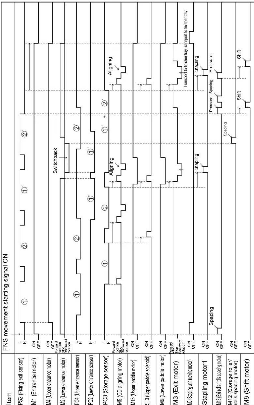
other
| Motor | Signal Type | Event Description | |-------|-------------|-------------------| | PS2 | Fixing exit sensor | L H ① ② ① ② | | M1 | Entrance motor | ON OFF | | M4 | Upper entrance motor | ON OFF Forward rotation Stop Backward rotation Switchback | | M2 | Lower entrance motor | Forward rotation Stop Backward rotation | | PC4 | Upper entrance sensor | L H ① ② ① ② | | PC2 | Lower entrance sensor | H L ① ① ① | | PC3 | Storage sensor | L H ① ② ① ② Aligning ① + ② Aligning | | M5 | CD aligning motor | Forward rotation Stop Backward rotation | | M15 | Upper paddle motor | ON OFF | | SL3 | Upper paddle solenoid) | ON OFF | | M9 | Lower paddle motor | ON OFF | | M3 | Exit motor | Forward rotation Stop Backward rotation | | M6 | Stapling unit moving motor | ON OFF | | Stapling motor1 | - | ON OFF Spacing | | M13 | Exit roller/rolls spacing motor) | ON OFF Spacing | | M12 | Storage roller/rolls spacing motor) | ON OFF Spacing | | M8 | Shift motor | ON OFF Shift Shift |D. Non-sort, hole punch, 1 original, 1 copy setting

other
| Signal | State | Description | | --- | --- | --- | | PS2 (Fixing exit sensor) | L | High frequency | | PS2 (Fixing exit sensor) | H | Low frequency | | M1 (Entrance motor) | ON | On/OFF | | M1 (Entrance motor) | OFF | Off | | M4 (Upper entrance motor) | ON | On/OFF | | M4 (Upper entrance motor) | OFF | Off | | SL1 (Upper/lower entrance switching solenoid) | ON | On/OFF | | SL1 (Upper/lower entrance switching solenoid) | OFF | Off | | SL2 (1st tray entrance selecting solenoid) | ON | On/OFF | | SL2 (1st tray entrance selecting solenoid) | OFF | Off | | M11 (Punch motor) | ON | On/OFF | | M11 (Punch motor) | OFF | Punching movement | | Punch clutch | ON | On/OFF | | Punch clutch | OFF | Punching movement | | PC1 (1st tray exit sensor) | L | High frequency | | PC1 (1st tray exit sensor) | H | Low frequency |5.10 FS-114 Timing Chart
A. Non-sort, 8.5x11, 1 copy setting
1

text_image
Transport sensor (PC5-FN) ON OFF Entrance motor (M3-FN) Forward Stop Transport motor (M2-FN) High Low Stop Exit motor (M1-FN) Forward Stop4349T506BA
B. 1 staple, 2 holes, 8.5x11, 2 originals, 2 sets setting
→
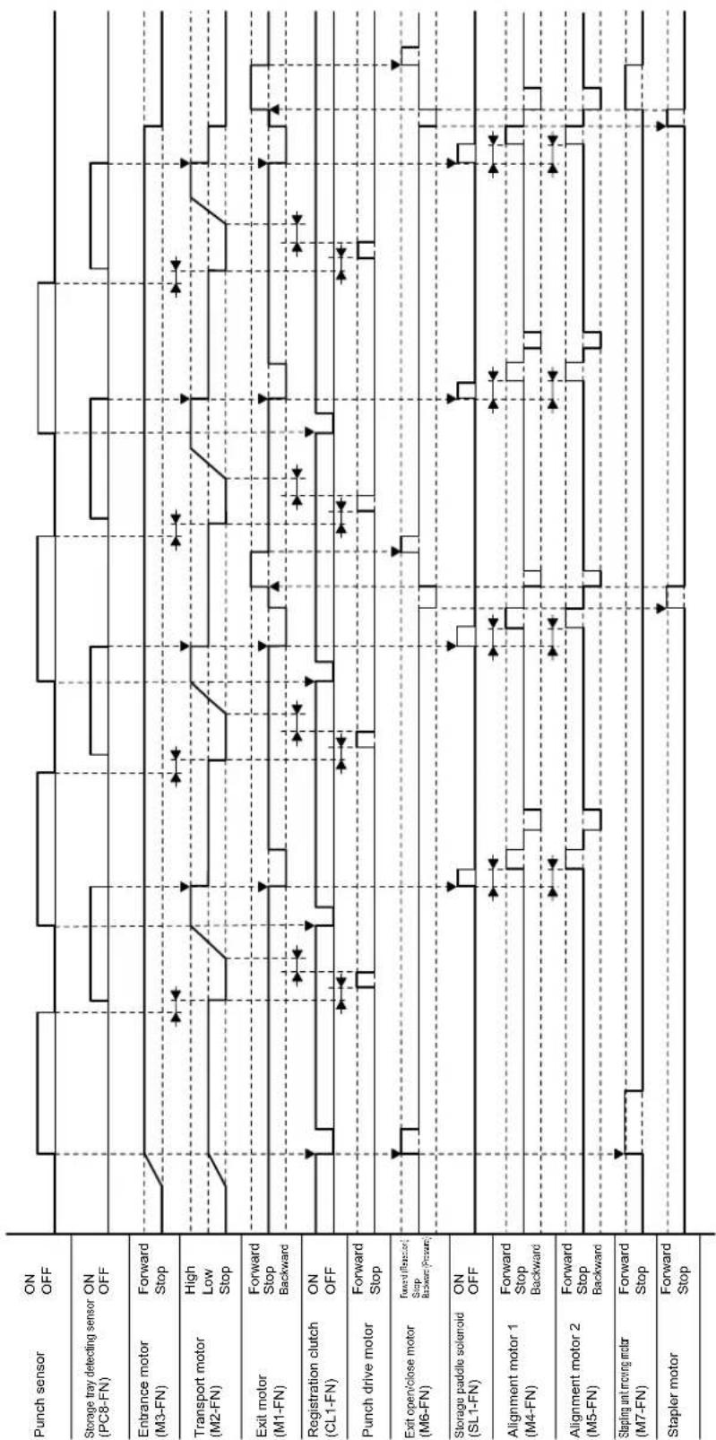
other
| Sensor Type | Signal State | Notes | | --- | --- | --- | | Punch sensor | ON OFF | | | Storage tray detecting sensor (PC8-FN) | ON OFF | | | Entrance motor (M3-FN) | Forward Stop | | | Transport motor (M2-FN) | High Low Stop | | | Exit motor (M1-FN) | Forward Stop Backward | | | Registration clutch (CL1-FN) | ON OFF | | | Punch drive motor | Forward Stop | | | Exit open/close motor (M6-FN) | Forward (Reassort) Stop Backward (Previous) | | | Storage paddle solenoid (SL1-FN) | ON OFF | | | Alignment motor 1 (M4-FN) | Forward Stop Backward | | | Alignment motor 2 (M5-FN) | Forward Stop Backward | | | Stapling unit moving motor (M7-FN) | Forward Stop | | | Stapler motor | Forward Stop | |4349T505BA
5.11 SK-114 Timing Chart
A. Booklet-binding, 2-point stapling, 8.5x11R, 2 originals, 1 set setting
1

other
| Sensor Type | Motor | State | Value | | --- | --- | --- | --- | | Punch sensor | PC8-FN | ON/OFF | ON | | Storage tray detecting sensor | PC8-FN | ON/OFF | ON | | Entrance motor | M3-FN | High/Low/Stop | High | | Transport motor | M2-FN | High/Low/Stop | High | | Exit motor | M1-FN | Forward/Stop/Backward | Forward | | Registration clutch | CL1-FN | ON/OFF | ON | | Crease motor | M10-SK | Forward/Stop | Forward | | Exit open/close motor | M6-FN | Forward/Stop/Backward | Forward | | Storage paddle solenoid | SL1-FN | ON/OFF | ON | | Alignment motor 1 | M4-FN | Forward/Stop/Backward | Forward | | Alignment motor 2 | M4-FN | Forward/Stop/Backward | Forward | | Saddle exit open/close motor | M9-SK | Forward/Stop/Backward | Forward | | Stapler motor 1 | - | Forward/Stop | Forward | | Stapler motor 2 | - | Forward/Stop | Forward | | Saddle exit motor | M8-SK | Forward/Stop | Forward |4511T504BA
Blank page
6. OVERALL WIRING DIAGRAM
6.1 DF-318/320 Overall Wiring Diagram
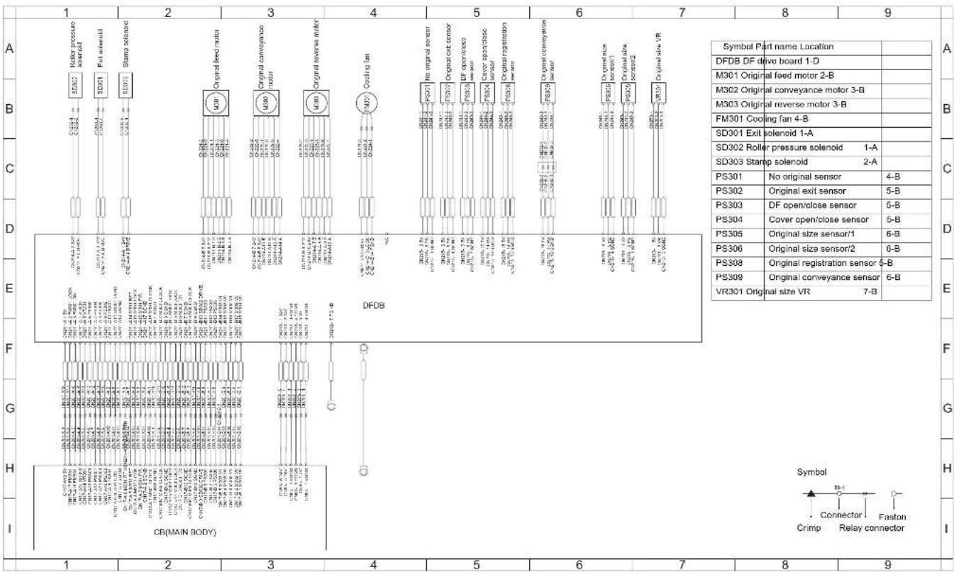
other
| Panel | Component Name | Symbol | |-------|-----------------------------------|--------| | A | Motor pressure solenoid | SDM2 | | A | Full row motor | SOD1 | | A | Stamp solenoid | SOD3 | | B | Original feed motor | UQJ | | B | Original conveyor motor | UQJ | | B | Original reverse motor | UQJ | | C | Coating fan | UQJ | | C | No integral sensor | PSD1 | | C | Original cut sensor | PSD2 | | C | DF open/close sensor | PSD3 | | C | Cover open/close sensor | PSD4 | | C | Original registration sensor | PSD5 | | D | Original conveyance sensor | PSD6 | | D | Original ramp voler 2-A | PSD7 | | D | Original ramp voler 2-A | PSD8 | | E | PS301: No original sensor | PS301 | | E | PS302: Original exit sensor | PS302 | | E | PS303: DF open/close sensor | PS303 | | E | PS304: Cover open/close sensor | PS304 | | E | PS305: Original size sensor'1 | PS305 | | E | PS306: Original size sensor'2 | PS306 | | E | PS308: Original registration sensor 5-B | PS308 | | E | PS309: Original conveyance sensor 6-B | PS309 | | F | VR301: Original size VR | VR301 | | G | CR(MAIN BODY) | CR-MAIN BODY | | H | CR-MAIN BODY | CR-MAIN BODY | | I | CR-MAIN BODY | CR-MAIN BODY | Symbol: 55-1 Connector: Faston Crimp Relay connector6.2 DB-211/411 Overall Wiring Diagram
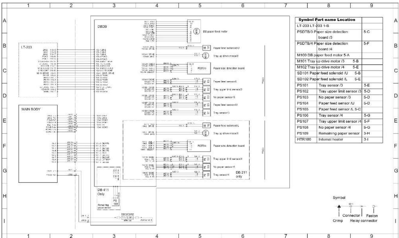
text_image
Symbol Part name Location LT-203 LT-203 1-B PSDTB/3 Paper size detection board /3 5-C PSDTB/4 Paper size detection board /4 5-F M100 DB paper feed motor 5-A M101 Tray up drive motor /3 5-B M102 Tray up drive motor /4 5-E SD101 Paper feed solenoid /U 5-B SD102 Paper feed solenoid /L 5-E PS101 Tray sensor /3 5-E PS102 Tray upper limit sensor /3 5-D PS103 No paper sensor /3 5-D PS104 Paper feed sensor /U 5-D PS105 Paper feed sensor /L 5-C PS106 Tray sensor /4 5-G PS107 Tray upper limit sensor /4 5-F PS108 No paper sensor /4 5-G PS109 Remaining paper sensor 3-H HTR100 Internal heater 3-I A B C D E F G H I 1 2 3 4 5 6 7 8 9 DBDB DB paper feed motor Paper feed solenoid/U Tray up drive motor/ Paper size detection board Paper feed sensor/ Tray upper limit sensor/ Paper feed sensor/ Tray sensor/ Paper feed solenoid/L Tray up drive motor/ Paper size detection board Tray upper limit sensor/ Tray upper limit sensor/ Tray sensor/daily DB-211 only DM-1.2.2.2.2.2.2.2.2.2.2.2.2.2.2.2.2.2.2.2.2.2.2.2.2.2.2.2.2.2.2.2.2.2.2.2.2.2.2.2.2.2.2.2.2.2.2.2.2.2.2.3 MAIN BODY DB-411 Only Remarling PSP 109 HRD 100 Symbol Connector Faston Crimp Relay connector6.3 LT-203 Overall Wiring Diagram

text_image
DB-211 DB-411 DBDB 105.1 2402 105.2 2370 065.3 2402 066.4 2402 108.1 1978 108.2 1978 108.3 1978 108.4 1978 108.5 1978 108.6 1978 108.7 1978 108.8 1978 108.9 1978 108.10 1978 108.11 1978 108.12 1978 108.13 1978 108.14 1978 108.15 1978 108.16 1978 108.17 1978 108.18 1978 108.19 1978 108.20 1978 LTDB 150.3 2402 150.4 2370 150.5 2402 150.6 2402 150.7 2402 150.8 2402 150.9 2402 LT paper feed motor (ENI) (N-CT) LT paper feed sensor LT paper feed sensor Paper feed sensor Tray upper limit sensor No paper sensor Removing paper sensor1 Removing paper sensor2 Symbol Part name Location DB-211 DB-211 1-B DB-411 DB-411 1-B M150 LT paper feed motor 6-C M151 Tray up drive motor 6-B SD161 LT paper feed sole-noid 6-D PS151 Remaining paper sensor /2 6-F PS152 Tray upper limit sensor 6-E PS153 No paper sensor 6 E PS154 Remaining paper sensor /1 6-F PS155 Paper feed sensor 6 D MS151 Interlock switch 6-A HTR150 Internal heater 4-G Symbol D- Connector Faston Crimp Relay connectorOVERALL WIRING DIAGRAM
Blank page
6.4 FS-112 Overall Wiring Diagram
flowchart
graph TD
    subgraph Main Body
        A["FSNCS"] --> B["FNSCB"]
        B --> C["Main Body"]
    end
    subgraph Control
        D["RS convection motor"] --> E["Paper set motor"]
        E --> F["Coating motor"]
        F --> G["Polar release salam"]
        G --> H["Amgen motor"]
        H --> I["Stapler movement motor"]
        I --> J["Trigger sensor"]
    end
    subgraph Power Supply
        K["Switch switch"] --> L["Front cover satur"]
        M["Switch sensor"] --> N["Pressure sensor"]
        O["Pressure unit"] --> P["Pressure unit"]
        Q["Turn-up/HP sensor"] --> R["Paper set sensor"]
        S["Paper set full sensor"] --> T["Turn-off sensor"]
        U["Turn-down/HP sensor"] --> V["Stopper motor"]
        W["Stopper IP sensor"] --> X["Stopper driver sensor"]
        Y["Stopper ready sensor"] --> Z["Stopper motor"]
    end
    subgraph Control Source
        AA["Main Body"] --> AB["Connector"]
        AC["Faston"]
    end
    subgraph Power Supply
        AD["RS convection motor"] --> AE["Paper set motor"]
        AF["Coating motor"] --> AG["Polar release salam"]
        AH["Amgen motor"] --> AI["Stapler movement motor"]
        AJ["Trigger sensor"] --> AK["Trigger sensor"]
    end
    subgraph Power Supply
        AL["Switch switch"] --> AM["Front cover satur"]
        AN["Switch sensor"] --> AO["Pressure sensor"]
        AP["Pressure unit"] --> AQ["Turn-up/HP sensor"]
        AR["Turn-down/HP sensor"] --> AS["Paper set sensor"]
        AT["Paper set full sensor"] --> AU["Turn-off sensor"]
        AV["Turn-down/HP sensor"] --> AW["Stopper motor"]
    end
    subgraph Power Supply
        AX["Switch switch"] --> AY["Front cover satur"]
        AZ["Switch sensor"] --> BA["Polar release salam"]
        BB["Polar unit"] --> BC["Amgen motor"]
        BD["Amgen motor"] --> BE["Trip output motor"]
    end
    subgraph Control Source
        BF["Main Body"] --> BG["Crimp"]
        BH["Faston"]
    end
OVERALL WIRING DIAGRAM
| Symbol Part name Location | ||
| FNSCB FNS control board 1-D | ||
| M701 FNS conveyance motor 1-H | ||
| M702 Paper exit motor 1-H | ||
| M703 Alignment motor /R 2-I | ||
| M704 Alignment motor /F 3-I | ||
| M705 Stapler movement motor 3-I | ||
| M706 Tray up/down motor 4-I | ||
| M707 Pressure motor 3-B | ||
| M708 Stapler motor 6-C | ||
| FM701 Cooling motor | 2-I | |
| SD701 | Roller release solenoid 2-H | |
| MS701 | Front door switch | 1-B |
| MS702 | Shutter switch | 1-B |
| PS701 | Pressure sensor | 2-B |
| PS702 | FNS entrance sensor | 2-B |
| PS703 | Paper exit sensor | 3-B |
| PS704 | Paper exit full sensor | 4-B |
| PS705 | Shutter sensor | 2-B |
| PS706 | Tray lower limit sensor | 4-B |
| PS707 | No paper sensor 5-B | |
| PS708 | Stapler unit HP sensor | 5-B |
| PS709 | Alignment HP sensor /R | 5-B |
| PS710 | Alignment HP sensor /F | 5-B |
| PS711 | Tray upper limit sensor 3-B | |
| PS712 | Stapler HP sensor 6-B | |
| PS713 | Staple detection sensor | 6-B |
| PS714 | Stapler ready sensor | 7-B |
| PS716 | Tray count sensor | 4-B |
6.5 RU-101 Overall Wiring Diagram
other
| Component | Terminal | Connection Type | Label | | :--- | :--- | :--- | :--- | | Main BODY | CN300-B3 | CN2008-5 | MRTS | | Main BODY | CN300-B4 | CN2008-3 | GND | | Main BODY | CN300-B6 | CN2008-4 | MRXD | | Main BODY | CN300-B8 | CN2008-2 | MRTS | | Main BODY | CN300-B10 | CN2008-6 | GND | | Main BODY | CN300-B11 | CN2008-7 | M1XD | | FUB | CN300-A5 | CN3-6 | CN4-1 | | FUB | CN300-A6 | CN3-5 | CN4-2 | | FUB | CN300-A7 | CN3-4 | | | FUB | CN300-A8 | CN3-3 | | | FUB | CN300-A9 | CN3-2 | | | FUB | CN300-A10 | CN3-1 | | | Passage sensor | PS2 | CN1-1 | CN200A-7 | | Passage sensor | PS2 | CN1-2 | CN200A-6 | | Passage sensor | PS2 | CN1-3 | CN200A-5 | | Front door sensor | PS1 | CN2-1 | CN200A-4 | | Front door sensor | PS1 | CN2-2 | CN200A-3 | | Front door sensor | PS1 | CN2-3 | CN200A-2 | | FS-113 Symbol (Symbol) (Symbol) (Symbol) (Symbol) (Symbol) (Symbol) (Symbol) (Symbol) (Symbol) (Symbol) (Symbol) (Symbol) (Symbol) (Symbol) (Symbol) (Symbol) (Symbol) (Symbol) (Symbol) (Symbol) (Symbol) (Symbol) (Symbol) (Symbol) (Symbol) (Symbol) (Symbol) (Symbol) (Symbol) (Symbol) (Symbol) (Symbol) (Symbol) (Symbol) - Connector Relay connector (Crimp) (9c-1) (Faston Relay connector) (Faston Relay connector) (Faston Relay connector) (Faston Relay connector) (Faston Relay connector) (Faston Relay connector) (Faston Relay connector) (Faston Relay connector) (Faston Relay connector) (Faston Relay connector) (Faston Relay connector) (Faston Relay connector) (Faston Relay connector) (Faston Relay connector) (Faston Relay connector) - Connector Relay connector (Faston Relay connector) (Faston Relay connector) (Faston Relay connector) (Faston Relay connector) (Faston Relay connector) (Faston Relay connector) (Faston Relay connector) (Faston Relay connector) (Faston Relay connector) (Faston Relay connector) (Faston Relay connector) (Faston Relay connector) (Faston Relay connector) (Faston Relay connector) (FS-113)OVERALL WIRING DIAGRAM
Blank page
6.6 FS-113 Overall Wiring Diagram

flowchart
graph TD
    A["1"] --> B["2"]
    B --> C["3"]
    C --> D["4"]
    D --> E["5"]
    E --> F["6"]
    F --> G["7"]
    G --> H["8"]
    H --> I["9"]

    subgraph Control Board
        J["Pin 1: Pulling Motor & Control Body"]
        K["Pin 2: Pulling Motor & Control Body"]
        L["Pin 3: Pulling Motor & Control Body"]
        M["Pin 4: Pulling Motor & Control Body"]
        N["Pin 5: Pulling Motor & Control Body"]
        O["Pin 6: Pulling Motor & Control Body"]
        P["Pin 7: Pulling Motor & Control Body"]
        Q["Pin 8: Pulling Motor & Control Body"]
        R["Pin 9: Pulling Motor & Control Body"]
    end

    subgraph Power Line
        S["Power Line: Pulling Motor & Control Body"]
        T["Power Line: Pulling Motor & Control Body"]
        U["Power Line: Pulling Motor & Control Body"]
        V["Power Line: Pulling Motor & Control Body"]
        W["Power Line: Pulling Motor & Control Body"]
        X["Power Line: Pulling Motor & Control Body"]
        Y["Power Line: Pulling Motor & Control Body"]
        Z["Power Line: Pulling Motor & Control Body"]
        AA["Power Line: Pulling Motor & Control Body"]
        AB["Power Line: Pulling Motor & Control Body"]
        AC["Power Line: Pulling Motor & Control Body"]
        AD["Power Line: Pulling Motor & Control Body"]
        AE["Power Line: Pulling Motor & Control Body"]
        AF["Power Line: Pulling Motor & Control Body"]
    end

    subgraph Control Panel
        AG["Pump Motor & Control Body"]
        AH["Pump Motor & Control Body"]
        AI["Pump Motor & Control Body"]
        AJ["Pump Motor & Control Body"]
        AK["Pump Motor & Control Body"]
        AL["Pump Motor & Control Body"]
        AM["Pump Motor & Control Body"]
        AN["Pump Motor & Control Body"]
        AO["Pump Motor & Control Body"]
        AP["Pump Motor & Control Body"]
        AQ["Pump Motor & Control Body"]
        AR["Pump Motor & Control Body"]
        AS["Pump Motor & Control Body"]
        AT["Pump Motor & Control Body"]
        AU["Pump Motor & Control Body"]
        AV["Pump Motor & Control Body"]
        AW["Pump Motor & Control Body"]
        AX["Pump Motor & Control Body"]
        AY["Pump Motor & Control Body"]
        AZ["Pump Motor & Control Body"]
        BA["Pump Motor & Control Body"]
        BB["Pump Motor & Control Body"]
        BC["Pump Motor & Control Body"]
        BD["Pump Motor & Control Body"]
        BE["Pump Motor & Control Body"]
        BF["Pump Motor & Control Body"]
        BG["Pump Motor & Control Body"]
        BH["Pump Motor & Control Body"]
        BI["Pump Motor & Control Body"]
        BJ["Pump Motor & Control Body"]
        BK["Pump Motor & Control Body"]
        BL["Pump Motor & Control Body"]
        BM["Pump Motor & Control Body"]
        BN["Pump Motor & Control Body"]
        BO["Pump Motor & Control Body"]
        BP["Pump Motor & Control Body"]
        BQ["Pump Motor & Control Body"]
        BR["Pump Motor & Control Body"]
    end

    subgraph Power Line
        CA["Pump Motor & Control Body"]
        CB["Pump Motor & Control Body"]
        CD["Pump Motor & Control Body"]
        DD["Pump Motor & Control Body"]
        DE["Pump Motor & Control Body"]
        EF["Pump Motor & Control Body"]
        GF["Pump Motor & Control Body"]
    end

    subgraph Power Line
        GH["Pump Motor & Control Body"]
        GH1["Pump Motor & Control Body"]
        GH2["Pump Motor & Control Body"]
        GH3["Pump Motor & Control Body"]
        GH4["Pump Motor & Control Body"]
        GH5["Pump Motor & Control Body"]
        GH6["Pump Motor & Control Body"]
    end

    subgraph Power Line
        GH1 --> GH2 --> GH3 --> GH4 --> GH5 --> GH6 --> GH7 --> GH8 --> GH9 --> GH10 --> GH11 --> GH12 --> GH13 --> GH14 --> GH15 --> GH16 --> GH17 --> GH18 --> GH19 --> GH20 --> GH21 --> GH22 --> GH23 --> GH24 --> GH25 --> GH26 --> GH27 --> GH28 --> GH29 --> GH30 --> GH31 --> GH32 --> GH33 --> GH34 --> GH35 --> GH36 --> GH37 --> GH38 --> GH39 --> GH40 --> GH41 --> GH42 --> GH43 --> GH44 --> GH45 --> GH46 --> GH47 --> GH48 --> GH49 --> GH50 --> GH51 --> GH52 --> GH53 --> GH54 --> GH55 --> GH56 --> GH57 --> GH58 --> GH59 --> GH60 --> GH61 --> GH62 --> GH63 --> GH64 --> GH65 --> GH66 --> GH67 --> GH68 --> GH69 --> GH70 --> GH71 --> GH72 --> GH73 --> GH74 --> GH75 --> GH76 --> GH77 --> GH78 --> GH79 --> GH80 --> GH81 --> GH82 --> GH83 --> GH84 --> GH85 --> GH86 --> GH87 --> GH88 --> GH89 --> GH90 --> GH91 --> GH92 --> GH93 --> GH94 --> GH95 --> GH96 --> GH97 --> GH98 --> GH99 --> SG100
    end

    subgraph Power Line
        BZ["Power Line: Pulling Motor & Control Body"]
        BZ1["Power Line: Pulling Motor & Control Body"]
        BZ2["Power Line: Pulling Motor & Control Body"]
        BZ3["Power Line: Pulling Motor & Control Body"]
    end

    subgraph Power Line
        BZ1P["Power Line: Pulling Motor & Control Body"]
        BZ2P["Power Line: Pulling Motor & Control Body"]
        BZ3P["Power Line: Pulling Motor & Control Body"]
    end

    subgraph Power Line
        BZ1A["Power Line: Pulling Motor & Control Body"]
        BZ2A["Power Line: Pulling Motor & Control Body"]
    end

    subgraph Power Line
        BZ1B["Power Line: Pulling Motor & Control Body"]
        BZ2B["Power Line: Pulling Motor & Control Body"]
    end

    subgraph Power Line
        BZ1C["Power Line: Pulling Motor & Control Body"]
        BZ2C["Power Line: Pulling Motor & Control Body"]
    end

    subgraph Power Line
        BZ1D["Power Line: Pulling Motor & Control Body"]
        BZ2D["Power Line: Pulling Motor & Control Body"]
    end

    subgraph Power Line
        BZ1E["Power Line: Pulling Motor & Control Body"]
        BZ2E["Power Line: Pulling Motor & Control Body"]
    end

    subgraph Power Line
        BZ1F["Power Line: Pulling Motor & Control Body"]
        BZ2F["Power Line: Pulling Motor & Control Body"]
    end

    subgraph Power Line
        BZ1G["Power Line: Pulling Motor & Control Body"]
        BZ2G["Power Line: Pulling Motor & Control Body"]
    end

    subgraph Power Line
        BZ1H["Power Line: Pulling Motor & Control Body"]
        BZ2H["Power Line: Pulling Motor & Control Body"]
    end

    subgraph Power Line
        BZ1I["Power Line: Pulling Motor & Control Body"]
        BZ2I["Power Line: Pulling Motor & Control Body"]
    end

    subgraph Power Line
        BZ1J["Power Line: Pulling Motor & Control Body"]
        BZ2J["Power Line: Pulling Motor & Control Body"]
    end

    subgraph Power Line
        BZ1K["Power Line: Pulling Motor & Control Body"]
        BZ2K["Power Line: Pulling Motor & Control Body"]
    end

    subgraph Power Line
        BZ1L["Power Line: Pulling Motor & Control Body"]
        BZ2L["Power Line: Pulling Motor & Control Body"]
    end

    subgraph Power Line
        BZ1M["Power Line: Pulling Motor & Control Body"]
        BZ2M["Power Line: Pulling Motor & Control Body"]
    end

    subgraph Power Line
        BZ1N["Power Line: Pulling Motor & Control Body"]
        BZ2N["Power Line: Pulling Motor & Control Body"]
    end

    subgraph Power Line
        BZ1O["Power Line: Pulling Motor & Control Body"]
        BZ2O["Power Line: Pulling Motor & Control Body"]
    end

    subgraph Power Line
        BZ1P["Power Line: Pulling Motor & Control Body"]
        BZ2P["Power Line: Pulling Motor & Control Body"]
    end

    subgraph Power Line
        BZ1Q["Power Line: Pulling Motor & Control Body"]
        BZ2Q["Power Line: Pulling Motor & Control Body"]
    end

    subgraph Power Line
        BZ1R["Power Line: Pulling Motor & Control Body"]
        BZ2R["Power Line: Pulling Motor & Control Body"]
    end

    subgraph Power Line
        BZ1S["Power Line: Pulling Motor & Control Body"]
        BZ2S["Power Line: Pulling Motor & Control Body"]
    end

    subgraph Power Line
        BZ1T["Power Line: Pulling Motor & Control Body"]
        BZ2T["Power Line: Pulling Motor & Control Body"]
    end

    subgraph Power Line
        BZ1U["Power Line: Pulling Motor & Control Body"]
        BZ2U["Power Line: Pulling Motor & Control Body"]
    end

    subgraph Power Line
        BZ1V["Power Line: Pulling Motor & Control Body"]
        BZ2V["Power Line: Pulling Motor & Control Body"]
    end

    subgraph Power Line
        BZ1W["Power Line: Pulling Motor & Control Body"]
        BZ2W["Power Line: Pulling Motor & Control Body"]
    end

    subgraph Power Line
        BZ1X["Power Line: Pulling Motor & Control Body"]
        BZ2X["Power Line: Pulling Motor & Control Body"]
OVERALL WIRING DIAGRAM
| Symbol Part name Location | ||
| RU-101 RU-101 1-F | ||
| M1 Transport motor 3-B | ||
| M2 Lower entrance motor 3-A | ||
| M3 Exit motor 2-A | ||
| M4 Upper entrance motor 3-B | ||
| M5 CD aligning motor 5-B | ||
| M6 Stapling unit moving sensor 3-A | ||
| M7 Elevator motor 1-D | ||
| M8 Shift motor 1-C | ||
| M9 Lower paddle motor 5-A | ||
| M11 Punch motor | 1-C | |
| M12 | Storage roller/rolls spacing motor | 2-A |
| M13 | Exit roller/rolls spacing motor | 7-D |
| M14 | Hole punch selector motor | 7-A |
| M15 | Upper paddle motor | 7-D |
| CL | Punch clutch | 6-A |
| SL1 | Upper/Lower entrance switching solenoid | 7-E |
| SL2 | 1st entrance switching solenoid | 7-E |
| SL3 | Upper paddle solenoid | 7-D |
| S1 | Set switch | 1-E |
| S2 | Elevator tray upper limit switch | 1-E |
| S3 | Elevator tray lower limit switch | 1-D |
| S4 | Hole punch position switch | 7-A |
| PC1 | 1st tray exit sensor | 7-G |
| PC2 | Lower entrance sensor | 7-G |
| PC3 | Storage sensor | 5-H |
| PC4 | Upper entrance sensor 5-H | |
| PC5 | Finisher tray paper detecting sensor | 2-I |
| PC6 | 1st tray full detecting sensor | 7-F |
| PC7 | Elevator tray full detecting sensor | 7-H |
| PC8 | Elevator tray paper detecting sensor | 2-H |
| PC9 | CD aligning home position sensor | 2-I |
| PC10 | Shift home position sensor | 2-H |
| PC11 | Shift motor pulse sensor | 2-H |
| PC12 | Storage roller home position sensor | 5-H |
| PC13 | Exit roll home position sensor | 7-H |
| PC14 | Staple home position sensor | 6-I |
| PC15 | Punch motor pulse sensor | 6-B |
| PC17 | Front door detecting sensor | 7-F |
| PC18 | Upper cover detecting sensor | 7-F |
| PS1 Front door sensor (RU-101) 7-B | ||
| PS2 Passage sensor (RU-101) | 7-B | |
| PWB-C | Elevator tray upper limit sensor LED | 7-E |
| PWB-D | Elevator tray upper limit sensor PQ | 5-I |
6.7 SK-114 Overall Wiring Diagram
| Symbol Part name Location | ||
| FS-114 FS-114 4-H, 7-E | ||
| M8-SK Saddle exit motor 3-I | ||
| M9-SK Saddle exit open/close motor 3-H | ||
| M10-SK Crease motor 7-G | ||
| M13-SK In & out guide motor 3-H | ||
| M14-SK Layable guide motor 3-G | ||
| PC18-SK Saddle exit roller home position sensor 7-A | ||
| PC20-SK Saddle exit sensor 7-B | ||
| PC21-SK Saddle tray empty sensor | 7-A | |
| PC22-SK Crease roller home position sensor 7-H | ||
| PC23-SK In & out guide home position sensor | 7-B | |
| PC25-SK Transport pulse sensor | 7-C | |
| PC26-SK Layable guide home sensor | 7-C | |
| S4-SK | Saddle interlock switch | 2-D |
| PWB-C SK | Main control board | 3-A |
APPENDIX
7. APPENDIX
7.1 7145 Overall Wiring Diagram (1/4)
△
flowchart
graph TD
    subgraph Input
        A["Input A"] --> B["DCPS"]
        C["Input B"] --> D["DCPS"]
        E["Input C"] --> F["DCPS"]
        G["Input D"] --> H["DCPS"]
        I["Input E"] --> J["DCPS"]
        K["Input F"] --> L["DCPS"]
        M["Input G"] --> N["DCPS"]
        O["Input H"] --> P["DCPS"]
        Q["Input I"] --> R["DCPS"]
    end

    subgraph Outputs
        S["DCPS"] --> T["DCPS"]
        U["DCPS"] --> V["DCPS"]
        W["DCPS"] --> X["DCPS"]
        Y["DCPS"] --> Z["DCPS"]
        AA["DCPS"] --> AB["DCPS"]
        AC["DCPS"] --> AD["DCPS"]
        AE["DCPS"] --> AF["DCPS"]
        AG["DCPS"] --> AH["DCPS"]
        AI["DCPS"] --> AJ["DCPS"]
        AK["DCPS"] --> AL["DCPS"]
        AM["DCPS"] --> AN["DCPS"]
        AO["DCPS"] --> AP["DCPS"]
        AQ["DCPS"] --> AR["DCPS"]
        AS["DCPS"] --> AT["DCPS"]
        AU["DCPS"] --> AV["DCPS"]
        AW["DCPS"] --> AX["DCPS"]
        AY["DCPS"] --> AZ["DCPS"]
    end

    subgraph Outputs
        BA["PAKB"] --> BB["OB"]
        BC["LCD8"] --> BD["BL"]
        BE["INV2"] --> BF["PSW2B /SW2"]
        BG["PACB"] --> BH["PCB"]
        BI["PACB"] --> BJ["PACB"]
        BK["PACB"] --> BL["PACB"]
        BN["PACB"] --> BO["PACB"]
        BP["PACB"] --> BP["PACB"]
        BP["PACB"] --> BP["PACB"]
        BP["PACB"] --> BP["PACB"]
        BP["PACB"] --> BP["PACB"]
        BP["PACB"] --> BP["PACB"]
        BP["PACB"] --> BP["PACB"]
        BP["PACB"] --> BP["PACB"]
    end

    subgraph Outputs
        BS["SCB 1/3"]
        BT["Symbol"]
        BU["Crimp"]
        BV["Faston"]
    end

    style Inputs fill:#f9f,stroke:#333
    style Outputs fill:#ccf,stroke:#333
Appendix-1
APPENDIX
7.2 7145 Overall Wiring Diagram (2/4)

other
| Component | Label | | --------- | -------------------------- | | A | | | B | | | C | | | D | | | E | | | F | | | G | | | H | | | I | | | ADB | ADB | | FK-102/FL-102 | FK-102/FL-102 | | CN37 Board to Board Connector | CN37 Board to Board Connector | | HD-103 Type A DIMM | HD-103 Type A DIMM | | PRMB | PRMB | | FANBattery | FANBattery | | SCB 2/3 | SCB 2/3 |Appendix-2
APPENDIX
7.3 7145 Overall Wiring Diagram (3/4)

text_image
LT-203 FS-112 FS-113 FS-114 Symbol Connector Fason Crimp Relay connector DF-318 CB 1/2 COPY VENDER Copy Vender Copy Vender Copy Vender Copy Vender Copy Vender Copy Vender Copy Vender Copy Vender Copy Vender Copy Vender Copy Vender Copy Vender Copy Vender Copy Vender Copy Vender Copy Vender Copy Vender Copy Vender Copy Vender Copy Vender Copy Vender Copy Vender Copy Vender Copy Vender Copy Vender Copy Vendeer Copy Vendeer Copy Vendeer Copy Vendeer Copy Vendeer Copy Vendeer Copy Vendeer Copy Vendeer Copy Vendeer Copy Vendeer Copy Vendeer Copy Vendeer Copy Vendeer Copy Vendeer Copy Vendeer Copy Vendeer Copy Vendeer Copy Vendeer Copy Vendeer Copy Vendeer Copy Vendeere Copy Vendeere Copy Vendeere Copy Vendeere Copy Vendeere Copy Vendeere Copy Vendeere Copy Vendeere Copy Vendeere Copy Vendeere Copy Vendeere Copy Vendeere Copy Vendeere Copy Vendeere Copy Vendeere Copy Vendeere Copy Vendeere Copy Vendeere Copy Vendeere Copy Vendeere Copy Vendeeres Copy Vendeeres Copy Vendeeres Copy Vendeeres Copy Vendeeres Copy Vendeeres Copy Vendeeres Copy Vendeeres Copy Vendeeres Copy Vendeeres Copy Vendeeres Copy Vendeeres Copy Vendeeres Copy Vendeeres Copy Vendeeres Copy Vendeeres Copy Vendeeres Copy Vendeeres Copy Vendeeres Copy Vendeeres Copy VendeereAppendix-3
7.4 7145 Overall Wiring Diagram (4/4)
3

text_image
A B C D E F G H I 1 2 3 4 5 6 7 8 9 LDB INDEX SCDB IP-432 SCB 3/3 Symbol Connector Faston Crimp Relay connector CB 2/2 IT-101APPENDIX
3
Symbol Part name Location Symbol Part name Location Symbol Part name Location
| COPY VENDER COPY VENDER Appendix 3 1-M2 Scanner motor Appendix-4 2-E P62 | ||
| DB-211 | DB-211 | Appendix-1 2-C |
| DB-411 | D0-411 | Appendix-1 2-G |
| DIMM | DIMM | Appendix-2 3-F |
| FK-102/FL-102 | FK-102/FL-102 | Appendix-2 4-A |
| FS-112 | FS-112 | Appendix-3 4-A |
| FS-113 | FS-113 | Appendix-3 4-A |
| HD-105 Type A | HD-105 | Appendix-2 2-F |
| IP-432 | IP-432 | Appendix-4 7-A |
| IT-101 | IT-101 | Appendix-4 5-H |
| KC | Key counter | Appendix-4 3-F |
| LT-203 | LT-203 | Appendix-3 2-A |
| TC | Total counter | Appendix-3 5-I |
| DF-318 | DF-318 | Appendix-3 7-A |
| ADB | A/D conversion board | Appendix-2 1-C |
| CB | Main control board | Appendix-3 1-F |
| FCB | Fixing control board | Appendix-1 8-B |
| INDEX | Index sensor board | Appendix-4 3-B |
| L1INVS | Exposure lamp power supply board | Appendix-4 2-E |
| LCDB | Display board | Appendix-1 4-F |
| LOB | LD drive board | Appendix-4 2-B |
| CB | Operation board | Appendix-1 5-F |
| PARK | Panel key board | Appendix-1 4-F |
| PFDBL | Paper feed detection board L | Appendix-4 5-I |
| PFDR/U | Paper feed detection board U | Appendix-4 4-I |
| PRMS | Parameter memory board | Appendix-2 9-F |
| PSW2B | Power SW2 board | Appendix-1 6-I |
| SCB | System control board | Appendix-1 6-C |
| SCDB | Scanner drive board | Appendix-4 1-B |
| TCSB | Timer control sensor board | Appendix-3 9-D |
| DCPS | DC power supply unit | Appendix-1 1-A |
| HV | High voltage unit | Appendix-3 2-E |
| INV1 | Exposure lamp inverter | Appendix-4 2-D |
| INV2 | Display inverter | Appendix-1 4-II |
| CBR1 | Circuit breaker /1 | Appendix-1 2-A |
| CBR2 | Circuit breaker /2 | Appendix-1 2-B |
| NF | Noise filter | Appendix-1 3-A |
| L1 | Exposure lamp | Appendix-4 2-F |
| L2 | Fixing heater lamp f1 | Appendix-1 8-B |
| L3 | Fixing heater lamp f2 | Appendix-1 6-G |
| PCL | Pre-charging lamp | Appendix-3 7-D |
| TSL | Transfer synchronization lamp | Appendix-1 5-I |
| LCD | LCD | Appendix-1 4-F |
| BL | Back light | Appendix-1 4-H |
| M1 | Main mode | Appendix-3 2-I |
| mdx-4 7-1 | ||
| M3 | Developing motor | Appendix-3 8-4 |
| M4 | Toner supply motor #1 | Appendix-3 5-4 |
| M5 | Polyport motor | Appendix-3 7-0 |
| M6 | ADU motor | Appendix-4 5-4 |
| M7 | Tray motor #U | Appendix-3 9-4 |
| M8 | Tray motor #L | Appendix-3 7-4 |
| M9 | Paper feed motor | Appendix-3 3-4 |
| M10 | Toner supply motor #2 | Appendix-3 8-4 |
| M11 | Firing motor | Appendix-3 3-4 |
| PM1 | DCPS cooling fan | Appendix-1 6-F |
| PM2 | Firing cooling fan | Appendix-3 4-4 |
| PM3 | Internal dehumidifying fan #1 | Appendix-3 7-4 |
| PM4 | Internal cooling fan #1 | Appendix-3 9-4 |
| PM5 | Developing suction fan | Appendix-3 8-4 |
| PM6 | Internal dehumidifying fan #2 | Appendix-3 7-4 |
| PM7 | Internal cooling fan #2 | Appendix-3 9-4 |
| MC1 | Registration clutch | Appendix-3 6-4 |
| MC2 | Loop clutch | Appendix-4 6-4 |
| SD1 | 1st paper feed solderoid #U | Appendix-4 3-4 |
| SD2 | 1st paper feed solderoid #L | Appendix-4 2-4 |
| SD3 | By-pass paper feed solderoid | Appendix-4 3-4 |
| SD4 | Cleaning web solderoid | Appendix-3 6-4 |
| SD5 | ADU gate solderoid | Appendix-3 5-4 |
| SD7 | Separation class solderoid | Appendix-3 6-E |
| SD8 | Gate solderoid | Appendix-4 7-4 |
| SD9 | Toner solderoid | Appendix-3 4-4 |
| PS1 | Registration sensor | Appendix-4 1-4 |
| PS2 | Fixing cell sensor | Appendix-3 5-E |
| PS4 | ADU sensor | Appendix-4 4-4 |
| PS5 | Toner bottle sensor | Appendix-3 5-4 |
| PS7 | Upper limit sensor #U | Appendix-4 2-4 |
| PS8 | No paper sensor #U | Appendix-4 1-4 |
| PS9 | Tray set sensor #U | Appendix-4 1-4 |
| PS10 | Upper limit sensor #L | Appendix-4 5-4 |
| PS11 | No paper sensor #L | Appendix-4 5-4 |
| PS12 | Tray set sensor #L | Appendix-4 1-4 |
| PS13 | By-pass no paper sensor | Appendix-4 4-4 |
| PS14 | Scanner home position sensor | Appendix-4 3-E |
| PS15 | APS timing sensor | Appendix-4 3-E |
| PS17 | APS sensor | Appendix-4 3-E |
| PS20 | By-pass tray paper slot sensor | Appendix-4 3-4 |
| PS21 | Timing sensor #U | Appendix-4 2-4 |
| PS22 | Timing sensor #L | Appendix-4 2-4 |
| PS23 | IT and sensor #U | Appendix-4 7-4 |
| PS25 | IT door sensor | Appendix-4 7-I |
| TH1 | Fixing temperature sensor /1 | Appendix-3 5-E |
| TH2 | Fixing temperature sensor /2 | Appendix-3 5-E |
| HUM1 | Humidity sensor | Appendix-3 6-D |
| TD8 | Tenet density sensor | Appendix-3 5-E |
| TLD | Tenet level sensor | Appendix-3 5-I |
| TS | Thermosist | Appendix-1 8-A |
| SW1 | Main power switch | Appendix-1 6-C |
| SW2 | Sub power switch | Appendix-1 9-I |
| SW3 | Interlock switch | Appendix-1 5-E |
| VR1 | By-pass tray paper size VR | Appendix-4 9-I |
| PTC | PTC heater | Appendix-1 8-E |
| BATTERY | Battery | Appendix-2 2-G |
APPENDIX
7.5 7235/7228/7222 Overall Wiring Diagram (1/4)

text_image
Symbol Connector + Faston Crimp Relay connector A B C D E F G H I 1 2 3 4 5 6 7 8 9 DCPS DCPS PSY PAKB OB SCB 1/3 DB-211 DB-411 PLC00000000000000000000000000000000000000000000000000000000000000000000000000000000000000000000000000 INV2Appendix-6
APPENDIX
7.6 7235/7228/7222 Overall Wiring Diagram (2/4)

text_image
Symbol Connector Faston Crimp Relay connector A ADB FK-103/FL-103 CN55 Board to Board Connector B C D HD-103 Type A DIMM PRMB E Battery FAN SCB 2/3 G IP-424 H LDB INDEX I 1 2 3 4 5 6 7 8 9 1 2 3 4 5 6 7 8 9APPENDIX
7.7 7235/7228/7222 Overall Wiring Diagram (3/4)
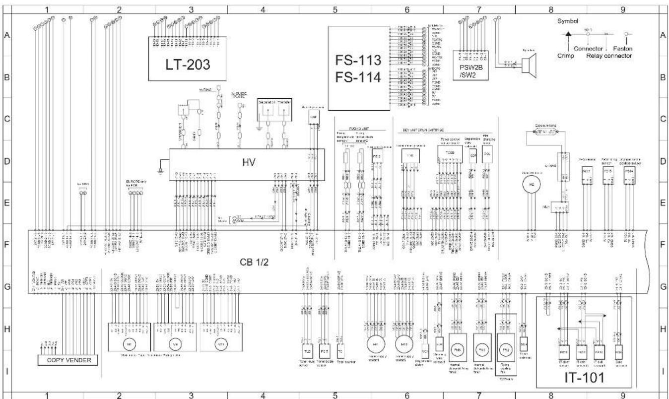
text_image
LT-203 FS-113 FS-114 PSW2B /SW2 Symbol Connector Crimp Faston Relay connector HV CB 1/2 COPY VENDER IT-101APPENDIX
7.8 7235/7228/7222 Overall Wiring Diagram (4/4)

text_image
DF-320 AD-307 (JAFLAN ONLY) ADUDB Symbol Connector Faster Crimp Relay connector SCB 3/3Appendix-9
APPENDIX
3
Symbol Part name Location Symbol Part names Location Symbol Part names Location
COPY VENDER COPY VENDER Appendix-3 14 M1 Maln motor Appendix-3 2-H PS24 IT seal sensor I Appendix
AD-307 AD-307 Appendix-4 5-C M2 Scanner motor Appendix-3 8-D PS25 IT door sensor Appendix-3 8-H
| DB-211 | DO-211 | Appendix-1 2-G |
| DB-411 | DB-411 | Appendix-1 2-G |
| DF-320 | DF-320 | Appendix-1 1-B |
| DIMM | DIMM | Appendix-2 3-D |
| FK-103/FL-103 | FK-103/FL-103 | Appendix-2 4-A |
| FS-113 | FS-113 | Appendix-3 5-A |
| FG-114 | FG-114 | Appendix-3 5-A |
| HD-103 Type A | HD-103 | Appendix-2 1-D |
| IP-124 | IP-124 | Appendix-2 8-D |
| IT-101 | IT-101 | Appendix-3 8-G |
| KC | Key counter | Appendix-4 1-D |
| LT-203 | LT-203 | Appendix-3 2-A |
| TC | Total counter | Appendix-3 5-H |
| AOS | A/D conversion board | Appendix-2 1-A |
| AOUTR | ADU drive board | Appendix-4 8-C |
| CB | Math control board | Appendix-3 1-F |
| PCB | Fixing central board | Appendix-1 5-B |
| INDEX | Index sensor board | Appendix-2 2-H |
| L1NVB | Exposure lamp power supply board | Appendix-3 8-D |
| LCDB | Display board | Appendix-1 5-G |
| LOB | LB drive board | Appendix-2 1-H |
| CB | Operation board | Appendix-1 9-F |
| PAVB | Panel key board | Appendix-1 4-F |
| PDBCL | Paper feed detection board iL | Appendix-4 6-H |
| PFDBU | Paper feed detection board iU | Appendix-4 5-H |
| PYWD | Parameter memory board | Appendix-2 4-D |
| PSW2B | Power GW2 board | Appendix-3 7-A |
| SOB | System control board | Appendix-1 8-E |
| TCSB | Timer control sensor board | Appendix-3 9-D |
| DCPS | DC power supply unit | Appendix-1 1-A |
| HV | High voltage unit | Appendix-3 3-D |
| INV1 | Exposure lamp inverter | Appendix-3 9-E |
| INV2 | Display inverter | Appendix-1 4-I |
| CRR1 | Circuit breaker #1 | Appendix-1 2-A |
| CRR2 | Circuit breaker #2 | Appendix-1 2-U |
| NF | Noise filter | Appendix-1 3-A |
| L1 | Exposure lamp | Appendix-3 8-C |
| L2 | Fixing heater lamp #1 | Appendix-1 7-B |
| L3 | Fixing heater lamp #2 | Appendix-1 7-B |
| PCL | Pre-charging lamp | Appendix-3 7-D |
| TSL | Transfer synchronization lamp | Appendix-4 5-I |
| LCD | LCD | Appendix-1 5-G |
| BL | Back light | Appendix-1 4-H |
| x3 9-H | ||
| M4 | Toner supply motor /I | Appendix-3 5-H |
| M5 | Polygan motor | Appendix-4 4-A |
| M6 | ADU motor | Appendix-1 5-D |
| M7 | Tray motor /U | Appendix-4 7-I |
| M8 | Tray motor /L | Appendix-4 8-I |
| M9 | Paper feed motor | Appendix-3 3-H |
| M10 | Toner supply motor /2 | Appendix-3 6-H |
| M11 | Ficking motor | Appendix-4 7-I |
| FM1 | DCPS cooling fan | Appendix-1 4-F |
| FM2 | Ficking cooling fan | Appendix-3 7-H |
| FM3 | Internal dehumidifying fan /I | Appendix-3 7-H |
| FM4 | Internal cooling fan /I | Appendix-1 4-I |
| FM5 | Developing suction fan | Appendix-4 4-I |
| FM6 | Internal dehumidifying fan /2 | Appendix-3 7-H |
| FM7 | Polygan cooling fan | Appendix-1 4-D |
| MC1 | Registration clutch | Appendix-3 6-H |
| MC2 | Loop clutch | Appendix-4 4-I |
| SD1 | 1st paper fove solenoid /U | Appendix-4 2-I |
| SD2 | 1st paper fove solenoid /L | Appendix-4 2-I |
| SD3 | By-pass paper feed solenoid | Appendix-4 3-I |
| SD4 | Clearing web solenoid | Appendix-3 6-H |
| SD5 | ADU gate solenoid | Appendix-4 6-D |
| SD7 | Separation drain solenoid | Appendix-3 7-D |
| SD8 | Gate solenoid | Appendix-3 9-H |
| SD9 | Toner solenoid | Appendix-3 8-H |
| PS1 | Registration sensor | Appendix-4 1-I |
| PS2 | Fitting cell sensor | Appendix-3 6-D |
| PS4 | ADU sensor | Appendix-4 6-D |
| PS5 | Toner bottle sensor | Appendix-3 5-H |
| PS7 | Upper limit sensor /U | Appendix-4 2-I |
| PS8 | No paper sensor /L | Appendix-4 2-I |
| PS9 | Tray set sensor /U | Appendix-4 1-I |
| PS10 | Upper limit sensor /L | Appendix-4 5-I |
| PS11 | No paper sensor /U | Appendix-1 5-I |
| PS12 | Tray set sensor /L | Appendix-4 1-I |
| PS13 | By-pass no paper sensor | Appendix-4 3-I |
| PS14 | Scanner home position sensor | Appendix-3 9-D |
| PS15 | APS timing sensor | Appendix-3 9-D |
| PS17 | APS sensor | Appendix-3 8-D |
| PS20 | By-pass tray paper size sensor | Appendix-1 3-I |
| PS21 | Timing sensor /U | Appendix-4 7-I |
| PS22 | Timing sensor /L | Appendix-4 2-I |
| PS23 | IT test sensor /U | Appendix-3 8-I |
| TH1 | Fixing temperature sensor /1 | Appendix-3 5-D |
| TH2 | Fixing temperature sensor /2 | Appendix-3 6-D |
| HUM1 | Humidity sensor | Appendix-3 5-C |
| TDS | Toner density sensor | Appendix-3 6-D |
| TLD | Toner level sensor | Appendix-3 5-H |
| TS | Thermode | Appendix-1 7-A |
| SW1 | Main power switch | Appendix-1 6-C |
| SW2 | Sub power switch | Appendix-3 7-A |
| SW3 | Interlock switch | Appendix-1 5-E |
| VR1 | By pass into paper size VR | Appendix-4 3-I |
| PTC | PTC heater | Appendix-1 6-E |
| BATTERY | Battery | Appendix-2 1-E |
APPENDIX
7.9 FS-114 Overall Wiring Diagram
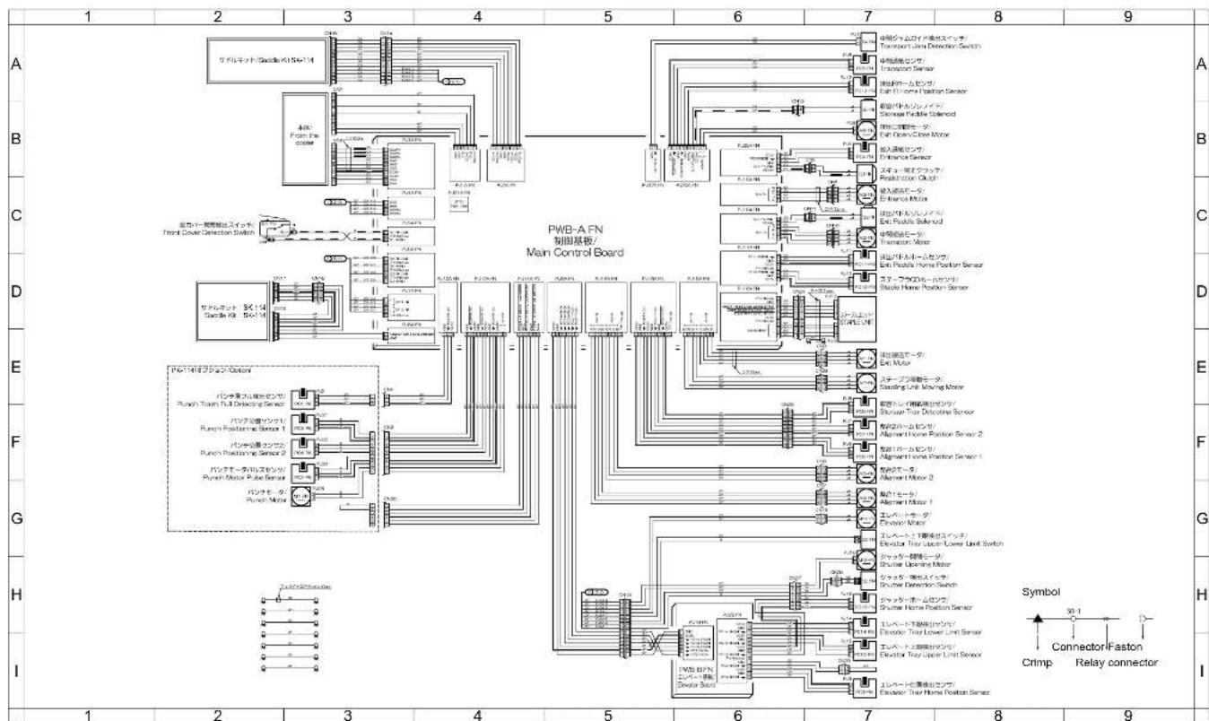
flowchart
graph TD
    A["传感器"] --> B["从前线"]
    B --> C["输入信号"]
    C --> D["输出信号"]
    D --> E["主控板"]
    E --> F["控制面板"]
    F --> G["输出端口"]
    style A fill:#f9f,stroke:#333
    style B fill:#ccf,stroke:#333
    style C fill:#cfc,stroke:#333
    style D fill:#fcc,stroke:#333
    style E fill:#cff,stroke:#333
    style F fill:#ffc,stroke:#333
    style G fill:#cfc,stroke:#333
    subgraph PWB-A FN Main Control Board
        H["输入信号"] --> I["输出信号"]
        J["输出信号"] --> K["控制面板"]
        L["输入信号"] --> M["输出端口"]
    end
Appendix-11
APPENDIX
| Symbol Part name Location | ||
| PK-114 PK-114 1-E | ||
| SK-114 SK-114 1-A, 1-D | ||
| CL1-FN Registration clutch 7-B | ||
| M1-FN Exit motor 7-E | ||
| M2-FN Transport motor 7-C | ||
| M3-FN Entrance motor 7-C | ||
| M4-FN Alignment motor 1 7-G | ||
| M5-FN Alignment motor 2 7-F | ||
| M6-FN Exit open/close motor 7-B | ||
| M7-FN Stapling unit moving motor 7-E | ||
| M11-FN | Elevator motor | 7-G |
| M12-FN | Shutter opening motor 7-G | |
| PC3-FN | Elevator tray home position sensor | 7-I |
| PC4-FN | Entrance sensor | 7-B |
| PC5-FN | Transport sensor | 7-A |
| PC6-FN | Alignment home position sensor 1 7-F | |
| PC7-FN | Alignment home position sensor 2 7-F | |
| PC8-FN | Storage tray detecting sensor | 7-E |
| PC10-FN | Staple home position sensor | 7-D |
| PC11-FN | Exit paddle home position sensor | 7-D |
| PC12-FN | Exit roller home position sensor | 7-A |
| PC14-FN | Elevator tray lower limit sensor | 7-H |
| PC15-FN | Top face detection sensor | 7-I |
| PC16-FN | Shutter home position sensor | 7-H |
| S1-FN | Front cover open/close detection SW | 2-C |
| S2-FN | Shutter detection SW | 7-H |
| S3-FN | Elevate tray upper/lower limit SW | 7-G |
| S4-FN | Transport jam detection SW | 7-A |
| SL1-FN | Storage paddle solenoid | 7-B |
| SL2-FN | Exit paddle solenoid | 7-C |
| M1-PK Punch motor | 2-G | |
| PC1-PK | Punch trash full sensor | 2-E |
| PC2-PK | Punch motor pulse sensor | 2-F |
| PC3-PK | Punch positioning sensor 1 | 2-F |
| PC4-PK | Punch positioning sensor 2 | 2-F |
| PWB-A FN | Main control board | 3-B |
| PWB-B FN | Elevator board | 5-H |