LED-FA025i2220 - Screen NEC - Free user manual and instructions
Find the device manual for free LED-FA025i2220 NEC in PDF.

| Product Type | LED Monitor |
| Screen Size | 25 inches (diagonal) |
| Resolution | 1920 x 1080 (Full HD) |
| Aspect Ratio | 16:9 |
| Brightness | 250 cd/m² |
| Contrast Ratio | 1000:1 |
| Response Time | 5 ms |
| Viewing Angle | 178° horizontal / 178° vertical |
| Connectors | HDMI, VGA, Audio Out |
| Power Consumption | 25 W (typical), <0.5 W standby |
| Input Voltage | 100-240 V AC, 50/60 Hz |
| Weight (with stand) | 4.5 kg |
| Dimensions (with stand) | 560 x 420 x 180 mm |
| VESA Mount | 100 x 100 mm |
| Special Features | Flicker-free, Low Blue Light, Anti-glare coating |
| Included Accessories | Power cord, HDMI cable, Quick start guide |
| Cleaning Instructions | Use a soft, dry cloth; avoid solvents |
| Safety Precautions | Do not disassemble; keep away from water; ensure proper ventilation |
Frequently Asked Questions - LED-FA025i2220 NEC
User questions about LED-FA025i2220 NEC
0 question about this device. Answer the ones you know or ask your own.
Ask a new question about this device
Download the instructions for your Screen in PDF format for free! Find your manual LED-FA025i2220 - NEC and take your electronic device back in hand. On this page are published all the documents necessary for the use of your device. LED-FA025i2220 by NEC.
USER MANUAL LED-FA025i2220 NEC
Fine Pitch LED Video Display Indoor
NEC FA Series & FE Series LED Wall Bundle
Quick Start GUIDE
For models:
LED-FA012i2 (110 inch)
LED-FA015i2 (137 inch)
LED-FA019i2 (110 inch)
LED-FA019i2 (165 inch)
LED-FA025i2 (220 inch)
LED-FE012i2 (110 inch)
LED-FE015i2 (137 inch)
LED-FE019i2 (110 inch)
LED-FE019i2 (165 inch)
LED-FE025i2 (220 inch)
2020-08-18
Version 2.0
Languages:
English Page 3
Russian Page 19
Turkish Page 35
Arabic Page 51
Fine Pitch LED Video Display Indoor
NEC FA Series & FE Series LED Wall Bundle
Quick Start GUIDE - ENGLISH
For models:
LED-FA012i2 (110 inch)
LED-FA015i2 (137 inch)
LED-FA019i2 (110 inch)
LED-FA019i2 (165 inch)
LED-FA025i2 (220 inch)
LED-FE012i2 (110 inch)
LED-FE015i2 (137 inch)
LED-FE019i2 (110 inch)
LED-FE019i2 (165 inch)
LED-FE025i2 (220 inch)
2020-08-18
Version 2.0
Table of Contents
1. About this User Guide.... 5
1.1 Safety Symbols Used in this Manual 5
2. Safety and Compliance Guidelines.... 6
2.1 Qualification of Personnel....6
2.2 Personal Protection....6
2.3 General Safety Guidelines....6
2.3.1 Risk of Fire....7
2.4 Safety for Electricity and Power Supply 7
2.5 Safe Usage of LED Lamps....8
3. About The LED WALL......9
3.1 Turn on the LED Wall....9
4. The Video Controller ....11
4.1 Front and Rear Panel....11
4.2 Display and Menu 12
4.2.1 Select an Input Source 12
4.2.2 Adjust the Brightness....13
5. Troubleshooting....14
6. Disposal....15
6.1 Within the European Union.... 15
6.2 Outside the European Union 15
7. Copyright and Disclaimer ....16
7.1 Copyright 16
7.2 Disclaimer 16
8. Service & Support in Europe....17
1. About this User Guide
Dear customer,
Thank you for choosing one of NEC DISPLAY SOLUTIONS' fine pitch direct view LED display systems.
In this NEC Quick Start Guide, you can find a short overview about the components and handling of the LED Wall.
We hope your experience with our product meets or exceeds your expectations.
Please contact us if you have any questions.
1.1 Safety Symbols Used in this Manual
Safety instructions emphasize potential hazards for personal injury or property damage. This manual uses the following safety notices to indicate the severity of a potential hazard:
text_image
Warning sign with exclamation mark inside yellow triangle, commonly used for safety alerts
Warning!
A warning for a potentially hazardous situation that can result in death, personal injury, or property damage if not adhered to.
text_image
Yellow triangular warning sign with black exclamation mark, commonly used to indicate a hazard or alert event.
Caution!
A recommendation for a potentially hazardous situation that may result in personal injury or property damage if not adhered to.
Notice
A recommendation for a potentially hazardous situation that may result in property damage if not adhered to.
2. Safety and Compliance Guidelines
Read the instruction manuals carefully and follow the given instructions and safety information thoroughly.
The operating safety of the system is only ensured through its proper use.
Only operate the system with supplied accessories and tools.
2.1 Qualification of Personnel
Only authorized and qualified technical personnel can perform the installation.
Only personal qualified by NEC DISPLAY SOLUTIONS and/or respectively authorized personal may carry out repairs, service and maintenance work on the system. A case of service occurs as soon as one component is damaged in any way, is not fully functional any more.
Only trained personnel, such as electricians or NEC personnel, may connect the internal power supply to mains power supply.
2.2 Personal Protection

Warning!
Electric shock hazards.
Follow the relevant legal electric requirements of the country, where the system will be operated, as well as the existing regulations of the operator, such as work, operating and safety regulations.
2.3 General Safety Guidelines

Warning!
Risk of electric shock or fire due to high-voltage components.
- Do not expose this unit to rain or moisture.
- Do not submerge this unit partially, or completely in water, or liquids.
- Do not use this unit's polarized plug with an extension cord receptacle or other outlets unless the prongs can be fully inserted.
- Do not open the cabinet because of the high-voltage components inside. There are no user-serviceable parts are inside.
- Only qualified service personnel are allowed to service and open the unit.


Caution!
Risk of electric shock.
- If not in use, fully disengage the power to the unit by disconnecting the power cord from the AC outlet.
- Do not use damaged cables. Check cables regularly. Replace damaged cables immediately, they are not user-serviceable.
 | Caution! |  |
| Risk of fire and product damage by aggressive substances.Keep the system away from aggressive substances, inflammable gases and vapors.Clean the unit only with materials or chemicals that are inert, nonabrasive, noncorrosive and non-marking. Consult the manufacturer for further advice should any doubts exist regarding any cleaning procedure. | ||
 | Caution! | |
| Risk of fire, injuries and product damage.Keep the system away from flammable material.Never block the air ventilation spaces around the LED Wall. Keep them free at all times.Only use the supplied cables, which are fit for the system and its components. | ||
 | Caution! | |
| Risk of product damage due to dusty environment.Do not operate the system in a dusty environment. | ||
 | Caution! | |
| Risk of product damage by moisture or water.Do not clean the system with water. Do not wipe the LED Pixel Cards with a damp cloth. | ||
2.3.1 Risk of Fire
Keep flammable materials away from the installation. During operation a lot of energy is transferred into heat.
Proper ventilation must be provided. Never block the air ventilation holes. Keep them free at all times.
2.4 Safety for Electricity and Power Supply
The electrical systems and their components are not to be opened. The parts inside modules, which are not user-serviceable, hold high voltages, including when these components are not in-use for a long time. Accessing these components may lead to serious injury, or property damage.
Only authorized and qualified personnel may open the system and its components! All repairs to the system may only be carried out by NEC DISPLAY SOLUTIONS and/or by respectively authorized and qualified technical personnel.
- The limit values specified in the technical data must never be exceeded.
- Do not operate or touch the system with wet hands.
2.5 Safe Usage of LED Lamps
text_image
Yellow triangular warning sign with black lightning bolt symbol indicating electrical hazardCaution!
Risk of product damage due to static electricity and surge voltage.
Do not touch the LED display areas.

text_image
Yellow triangular warning sign with black exclamation mark, commonly used to indicate a hazard or alert event.Caution!
Risk of product damage due to moisture.
The LED lamps may absorb and hold moisture during the LED module installation or if not used for a long time. Therefore, in such cases, the brightness must be increased gradually during a break-in period before setting the normal brightness.
If the LED lamps are lit with 100% brightness while moisture is retained, the temperature will rise very quickly and the water inside the lamps will evaporate and expand. This will cause the encapsulating resin to expand, which may lead to separation of the boundary surface inside the LED lamps. This separation can cause the LED lamps not to light up properly.
Lamp break-in
Configure the brightness settings as shown below with a video displayed on the LED module. After a break-in period of approx. 3 hours, the LED module can be used under normal conditions.
Time since start-up:
0 hour 1 hour 2 hours 3 hours (just after start-up)
Full white
Brightness value 20%
50% 70% Normal operation
Video content
60%40% 80% Normal operation
3. About The LED WALL
The LED Wall is a high definition LED display product in 16:9 ratio with a high contrast ratio and refresh rate.
The LED Wall consists of single LED modules, which are interconnected and centrally controlled. The quantity of the modules depends on the size of your LED Wall.
To display videos, the LED Wall is connected to a video controller. The controller receives the video input and the control signal from PCs. The Controller converts the video input signal from the source and sends the video signal to the LED Wall. To monitor the input source, a regular screen can be connected to the video controller.

text_image
dvLED B C D I G F J H E DFigure 1: General Setup of the LED Wall and Video Controller
| A | LED Wall | F | Input Source for Monitoring |
| B | Video Controller (NovaStar MCTRL660 PRO) | G | Video Input to Video Controller |
| C | Video Output to LED Wall H Source PC with Video | Input Material | |
| D | Power Supply I Control Signal | ||
| E | Monitoring Screen J PC with Control Software NovaLCT | ||
3.1 Turn on the LED Wall
Notice
The electrical setup of the LED Wall and the video input setup depends on individual customer requirements. Below, you can find the most common setups. Before following the instructions, please ensure that your system fits one of the described setups.
How to turn on the LED Wall, depends on the electrical setup for the LED Wall.
1) The LED Wall is directly connected to mains
The LED Wall is always powered on and turns black if not needed (no video input).
- Ensure the video controller and the control PC is turned on.
- Start the video input on the PC with the video material. Result: The LED Wall displays the video material.
2) The LED Wall is has to be plugged in to mains (only for smaller LED Walls)
- Plug in the LED Wall to mains. The amount and type of plugs depends on the LED Wall setup and your region.
- Ensure the video controller and the control PC is turned on.
- Start the video input on the PC with the video material. Result: The LED Wall displays the video material.
3) Setup with SX ON/OFF Switch
The LED Wall and video controller are connected to a SX ON/OFF Switch, which turns the LED Wall and the video controller on and off.
- Press the SX ON/OFF Switch on the system control rack.
- Ensure the control PC is turned on.
- Start the video input on the PC with the video material. Result: The LED Wall displays the video material.
4. The Video Controller
| Notice | |
| The NovaStar Controller is no product of NEC DISPLAY SOLUTIONS.For detailed information on the NovaStar Controller, see the respective manual for NovaStar Controller MCTRL660 PRO. Download the current version at: https://www.novastar.tech/downloads/controller/ |  |
4.1 Front and Rear Panel
Front Panel
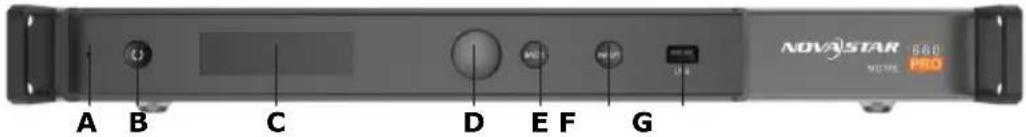
text_image
NOVA STAR 860 MUTE PROFigure 2: Front Panel of MCTRL660 PRO Video Controller
| A | LED: Green: normal operationRed: Standby mode | D Function knob: To navigate the menu* |
| E Back button: To go to previous menu | ||
| B Standby button F Input button: To select a video source | ||
| C Display G USB port: For firmware updates | ||
* How to use the Function knob:
• To enter a menu page or confirm an operation, press the Function knob.
• To select a menu item or adjust a menu parameter, rotate the Function knob.
- To lock or unlock all the buttons, press the Function knob and Back button simultaneously for 3 seconds.
Rear Panel
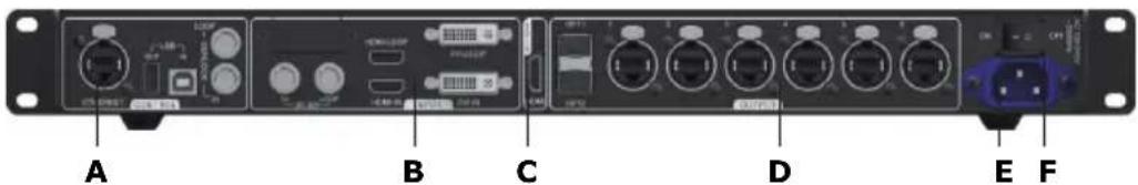
text_image
A B C D E FFigure 3: Rear Panel of MCTRL660 PRO Video Controller
| A Control: · Ethernet · USB In/Out · Genlock In/Loop | C Monitor, HDMI | |
| D Output: · OPT1, OPT2 (Optical ports) · RJ45, Ethernet ports 1–6 | ||
| B Input: · 3G-SDI In/Loop · HDMI In/Loop · DVI In/Loop | E | Power Switch |
| F | Power Supply (100 V – 240 V AC) | |
4.2 Display and Menu
For the LED Wall, the video controller is normally set to sending card mode. This means the video controller receives the video signal from a PC, processes the video signal and sends it to the LED Wall. The display of the video controller in normal operation (home screen) is shown below.

text_image
A MCTRL660 PRO B 192.168.0.10 C HDMI 1920x1080@60Hz DVI 4 5 6 3 Fiber 1 2 G F E DFigure 4: Display of Video Controller in Sending Card Mode
| A | Device Name E Screen brightness | ||
| B• | With Input Source: LED Wall resolution and color depth• No Input Source: Display control status | F | Operating Status (Backup, Alarms, Connected Ports) |
| G | Connection Status of Ethernet Ports | ||
| CIP Address or Sending Card Name H Video Source | |||
| DFront Panel Locked/Unlocked* | |||
* To lock or unlock all the buttons, press the Function knob and Back button simultaneously for 3 seconds.
4.2.1 Select an Input Source
The following input sources are supported:
• 3G-SDI
- Single-Link DVI
• HDMI
Select an input source that matches the type of the external video source.
Notice
The following constraints apply for the input sources:
- Only one video input source can be selected at the same time.
• Interlaced SDI video sources do not support low latency. -
SDI video sources do not support the following functions: Color depth adjustment, preset resolution, custom resolution, image mirroring.
-
On the home screen, press the Function knob to enter the menu.
- Select Input Settings and press the Function knob to see the settings.
- Select Input Source and press the Function knob to enter the submenu.
- Select the target video source and press the Function knob to enable it.
4.2.2 Adjust the Brightness
There are two ways to adjust the brightness of the LED Wall:
- Via Software NovaLCT on Control PC (also possible via remote access). For more information, see the Software Manual or the Complete Manual for the LED Wall.
- Via the video controller. The steps are as follows.
- On the home screen, press the Function knob to enter the menu.
- Select Brigthness and press the Function knob to enter the brightness menu.
- Rotate the Function knob to adjust the brightness value. The LED Wall displays the adjustment effect in real time.
- Press the Function knob to apply the brightness value.
5. Troubleshooting
Table 1: Troubleshooting Solutions summarizes the most common problems you could encounter with the appliance.
If you are unable to solve the problem with the information below, contact the NEC DISPLAY SOLUTIONS service team: LED-support@nec-displays.com
Table 1: Troubleshooting Solutions
| ProblemSolution | |
| Nothing is displayed on all LED modules. | Check that power is being supplied to the LED modules. |
| Check that the LED controller is turned on. | |
| Check that the LED controller has a video input signal. | |
| Check that a LAN cable is correctly connected between the LED controller and the LED module. | |
| Check that the brightness is not set to 0% (= not lit). | |
| Nothing is displayed on one LED module. | Check that a LAN cable is correctly connected between the LED controller and the LED module. |
| The Receiving card inside the LED module may be broken. Call a service technician. | |
| The power unit inside the LED module may be broken. Call a service technician. | |
| No image is displayed on one Pixel card. | The Pixel card may be broken. Call a service technician. |
| Control (communication) is not possible. | Check that the communication cable is correctly connected between the computer and the LED controller. |
| Check that the LED controller is turned on. | |
| If the communication cable is a USB cable, check that the device driver runs correctly. |
6.1 Within the European Union
WEEE Mark (European Directive 2012/19/EU and amendments)
natural_image
Symbol of a trash bin crossed with no text or numbers, representing waste sorting or disposal (no text present)Disposing of your used product: In the European Union
EU-wide legislation as implemented in each Member State requires that used electrical and electronic products carrying the mark (see on the left) must be disposed of separately from normal household waste. This includes monitors and electrical accessories, such as signal cables or power cords. When you dispose of such products, please follow the guidance of your local authority or ask the shop where you purchased the product, or if applicable, follow applicable legislation or agreement you may have. The mark on electrical and electronic products my only apply to the current European Member States.
6.2 Outside the European Union
If you wish to dispose of used electrical and electronic products outside the European Union, please contact your local authority and ask for the correct method of disposal.
7. Copyright and Disclaimer
7.1 Copyright
This document is © NEC DISPLAY SOLUTIONS, all rights reserved.
NEC is a registered trademark of NEC Corporation.
All product and company names are property of their respective owners. Use of them does not imply any affiliation with or endorsement by them.
The terms HDMI and HDMI High-Definition Multimedia Interface, and the HDMI Logo are trademarks or registered trademarks of HDMI Licensing Administrator, Inc. in the United States and other countries.
Microsoft and Windows 10 are registered trademarks of the Microsoft Corporation.
NovaStar and NovaLCT are registered trademarks of Xi'an NovaStar Tech Co., Ltd.
7.2 Disclaimer
All instructions and specifications in this manual are based on information available at the time of publishing for the features and safety guidelines of the described products.
Technical specifications, measurements, weights and properties are not guaranteed. The manufacturer reserves the right to make product alterations within legal provisions as well as changes to improve product quality.
NEC DISPLAY SOLUTIONS shall not be liable for personal injury or damage to materials caused by failure to observe this warning and safety information of this manual. Furthermore, NEC DISPLAY SOLUTIONS cannot be held responsible for damage or injury, caused by incorrect, inadequate or unsafe use, maintenance or installation of the entire system. The liability as well as the effects of the same will become void if other than genuine parts are used.
LOCAL REGULATIONS
This product and assembly variants that are shown in these instructions for assembly and use may be subject to local regulations, guidelines and norms.
The product use bears the responsibility for compliance to and with such regulations.
Subject to local regulations, we reserve the right not to supply all products illustrated here.
8. Service & Support in Europe
In case of questions feel free to contact us at the following address:
NEC Display Solutions Europe GmbH
Landshuter Allee 12–14
80637 Munich – Germany
Phone: +49 89 99 699 607
Fax: +49 89 99 699 500
E-Mail: LED-support@nec-displays.com
For the latest information please see
https://www.nec-display-solutions.com
Data is subject to change without notice.
Fine Pitch LED Video Display Indoor
text_image
Warning sign with exclamation mark inside yellow triangle, commonly used for safety alertsПРЕДУПРЕЖДЕНИЕ!
text_image
Yellow triangular warning sign with black exclamation mark symbolВнимание!
text_image
Yellow triangular warning sign with black lightning bolt symbol indicating electrical hazardВнимание!
text_image
Warning sign with yellow triangle and black exclamation mark symbolВнимание!
text_image
dvLED B C D I G F J H E Dnatural_image
Front view of a network equipment rack with multiple ports and connectors (no visible text or labels)ABCDEF
https://www.nec-display-solutions.com
Fine Pitch LED Video Display Indoor
NEC FA Series & FE Series LED Duvar Paketi
QUICK START GUIDE - TURKISH
Modeller:
LED-FA012i2 (110 inç)
LED-FA015i2 (137 inç)
LED-FA019i2 (110 inç)
LED-FA019i2 (165 inç)
LED-FA025i2 (220 inç)
LED-FE012i2 (110 inç)
LED-FE015i2 (137 inç)
LED-FE019i2 (110 inç)
LED-FE019i2 (165 inç)
LED-FE025i2 (220 inç)
2020-08-18
Sürüm 2.0
1. BU KULLANIM KILAVUZU HAKKINDA ....37
text_image
Warning sign with exclamation mark inside yellow triangle, commonly used for safety alertsUyari!
text_image
Yellow triangular warning sign with black exclamation mark symbolDikkat!
text_image
Yellow triangular warning sign with black lightning bolt symbol indicating electrical hazardDikkat!
text_image
Warning sign with yellow triangle and black exclamation mark symbolDikkat!
text_image
dvLED B C D J IG F H E Dnatural_image
Symbol of a trash bin crossed with no visible text or labelshttps://www.nec-display-solutions.com
Fine Pitch LED Video Display Indoor
NEC FA Series & FE Series
بقاة ج د ار الليد
.NEC DISPLAY SOLUTIONS
NEC DISPLAY SOLUTIONS
هل من قبل شركة
LED-support@nec-displays.com :SOLUTIONS
natural_image
Symbol of a trash bin crossed with a diagonal line, no text or numbers presentMunich – Germany 80637
+49 89 99 699 607 : الهاتف
https://www.nec-display-solutions.com