ANT2409v2 - Wi-Fi Antenna NETGEAR - Free user manual and instructions
Find the device manual for free ANT2409v2 NETGEAR in PDF.

| Product Type | Wi-Fi Antenna |
| Brand | NETGEAR |
| Model | ANT2409v2 |
| Frequency Bands | 2.4 GHz |
| Gain | 9 dBi |
| Polarization | Vertical |
| Connector Type | RP-SMA Male |
| Dimensions (W x H x D) | 120 x 120 x 80 mm |
| Weight | 0.3 kg (0.66 lb) |
| Operating Temperature | 0°C to 40°C (32°F to 104°F) |
| Power Supply | Passive (no external power required) |
| Mounting Type | Wall or desktop stand included |
| Compatibility | NETGEAR routers with removable antennas |
| Indoor/Outdoor Use | Indoor |
| Radiation Pattern | Omnidirectional |
| VSWR | < 2.0:1 |
| Impedance | 50 Ohms |
| Color | Black |
| Package Contents | 1 x Antenna, 1 x Mounting Kit, 1 x Quick Start Guide |
| Warranty | 1 year limited |
Frequently Asked Questions - ANT2409v2 NETGEAR
User questions about ANT2409v2 NETGEAR
0 question about this device. Answer the ones you know or ask your own.
Ask a new question about this device
Download the instructions for your Wi-Fi Antenna in PDF format for free! Find your manual ANT2409v2 - NETGEAR and take your electronic device back in hand. On this page are published all the documents necessary for the use of your device. ANT2409v2 by NETGEAR.
USER MANUAL ANT2409v2 NETGEAR
natural_image
White vertical antenna with metallic base and mounting bracket (no text or symbols visible)Installation Guide for the 9 dBi Omni-directional Antenna ANT2409
NETGEAR
NETGEAR, Inc. 4500 Great America Parkway Santa Clara, CA 95054 USA
201-11248-01 April 2008
© 2008 by NETGEAR, Inc. All rights reserved.
Trademarks
NETGEAR, the NETGEAR logo, and Smart Wizard are trademarks or registered trademarks of NETGEAR, Inc. Microsoft, Windows, and Windows NT are registered trademarks of Microsoft Corporation. Other brand and product names are registered trademarks or trademarks of their respective holders.
Statement of Conditions
In the interest of improving internal design, operational function, and/or reliability, NETGEAR reserves the right to make changes to the products described in this document without notice. NETGEAR does not assume any liability that may occur due to the use or application of the product(s) or circuit layout(s) described herein.
Federal Communications Commission (FCC) Compliance Notice: Radio Frequency Notice
In the U.S., the ANT2409 antenna should only be used with devices that have been FCC approved for use with it. Please check the NETGEAR web site at http://www.NETGEAR.com/go/antannas_fcc for an updated list of FCC approved devices.
European Emission Statement
For EU, use of any antenna requires careful planning and extra consideration to comply with EU emissions, health standards and regulations. It is recommended that a qualified professional installer service is consulted for site survey and proper installation. Antenna installation must comply with the maximum level authorized by each country. See http://www.NETGEAR.com/go/antannas_eu for product combinations that comply with EU regulations.
Contents
Chapter 1
Getting Started
Package Contents 1-1
Pole Mounting Configuration 1-3
Flat Surface Mounting Configuration 1-4
Placement and Other Important Considerations ....1-4
Chapter 2
Installing the Wireless Antenna
First, Assemble and Mount the Antenna 2-1
Now, Connect the Antenna 2-4
Connecting the Antenna for and Outdoor Installation 2-4
Connecting the Antenna for an Indoor Installation 2-5
Chapter 3
Specifications
Wireless Antenna and Mounting Assembly 3-1
2 Meter Antenna Cable 3-2
N/SMA Adaptor Accessory ....3-3
Lightning Arrestor Specifications 3-4
Radiation Patterns 3-5
Chapter 1 Getting Started
Thank you for purchasing the NETGEAR 9 dBi Omni-directional Antenna. This Installation Guide provides installation instructions and guidelines for using the wireless antenna.
Package Contents

text_image
NETGEAR Installation Guide, Warranty and Support information card Lightning arrester Reverse N/SMA adapter 2-meter cable 1. M5 Screws...... 4 pcs 2. Screws...... 4 pcs 3. Spring washer...... 4 pcs 4. Washe...... 4 pcs 5. Screw nute...... 4 pcs 6. Plastic fixing...... 4 pcs 2 U-bolts "L" bracket 9 dBi Omni-Directional Antenna ANT2409Figure 1-1
The package should contain the following items:
• NETGEAR 9 dBi Omni-directional Antenna
- 2-meter low loss antenna cable to connect the antenna to a lightning arrestor
• Lightning Arrestor

Note: A ground cable is not included but required for outdoor installation. The grounding cable must be equivalent or better than: AWG 10, UL 1015, Stranded, 600 V, 105°C, green or green/yellow insulation, 2 clip of 5.5 mm inner diameter cramped at both ends, cable no longer than 5 meters
- Reverse N/SMA Adapter
- Antenna mounting assembly (tube, grommet, 2 brackets, screws, washers)
• L shape bracket for top & ceiling mounting - Screws, bolts, washers, U-bolts and plastic anchors
- This Installation Guide, and a Warranty and Support Information card
If any of the parts are incorrect, missing, or damaged, contact your NETGEAR dealer. Keep the carton, including the original packing materials, in case you need to return the product for repair.
To obtain optimal results in extending wireless range with antenna installations, consult a qualified professional installer for site survey and installation assistance.
Antenna cable for connecting the wireless device is sold separately. Please use a NETGEAR model ACC-10314-01, 02, 03, 04, or 05 cable.
In the U.S., the ANT2409 antenna should only be used with devices that have been FCC approved for use with it. Please check the NETGEAR website at http://www.NETGEAR.com/go/antennas_fcc for an updated list of FCC approved devices.
For Europe, use of any antenna requires careful planning and extra consideration to comply with EU emissions and health standards and regulations. Antenna installation must comply with the maximum level authorized by each country.
Please check the NETGEAR website at
http://www.NETGEAR.com/go/antennas_eu for a list of restrictions and approved devices.
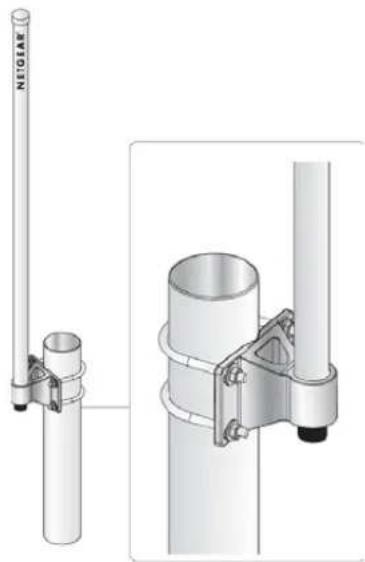
Pole Mounting Configuration
The following illustration shows the pole mount configuration option.

natural_image
Technical illustration of a vertical pole-mounted antenna with attached mounting bracket and cylindrical base (no text or symbols)Figure 1-2
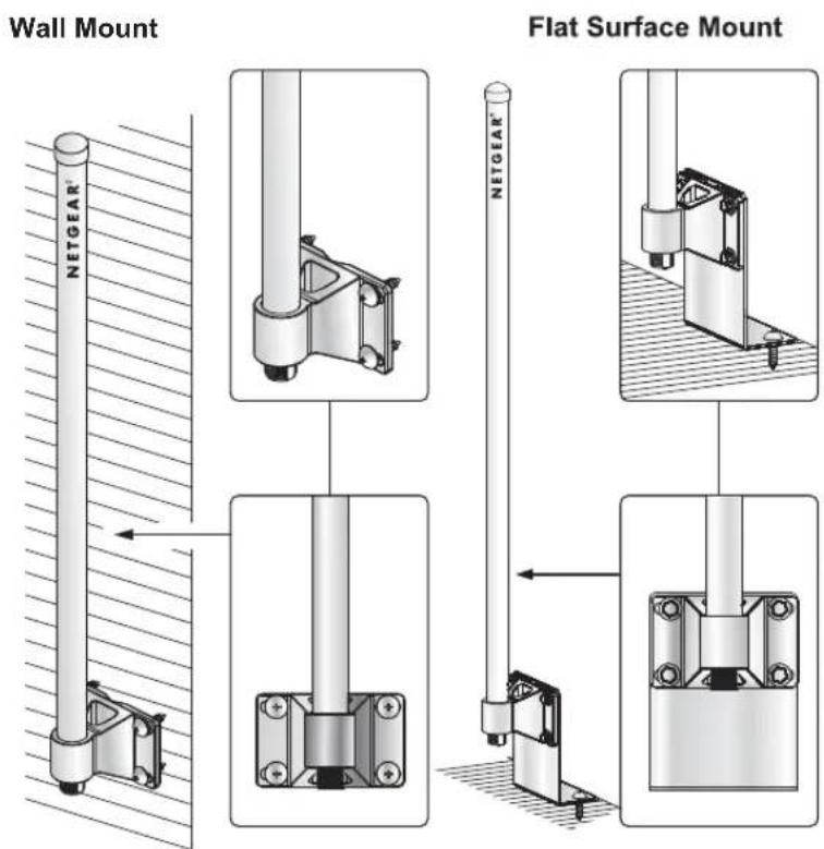
Flat Surface Mounting Configuration
This illustration shows a flat surface mount configuration.
text_image
Wall Mount Flat Surface Mount NETGEAR®Figure 1-3
For wall mount installation, the L-bracket is not used.
Placement and Other Important Considerations
Before installing your wireless antenna, observe the placement considerations. Antenna placement dramatically affects potential coverage. Follow these guidelines to maximize coverage:
- Place the antenna in a vertical position. Either right side up or up-side-down is OK.
- Place the antenna in the middle of the coverage zone and at 1.5 ~m or higher above the floor.
- Minimize obstructions around the antenna. Ideally there shall be a visual line of sight between the ANT2409 and the client antenna(s).
- High ceiling: place the ANT2409 in the center of the room installed up side down on a pole or on the ceiling with the L shape bracket.
- Outdoors: Place the ANT2409 on a roof fixed on a pole 2m above the roof level, or fixed directly on the roof near the edge, or against a wall, or on top of a telephone box. In most of the cases one ANT2409 is sufficient because the multipath fading is low or acceptable. However in cases where the building density is high, or narrow streets, or direct echo from another building, etc. two ANT2409 can improve the wireless performance (throughput and range). This latter is applicable only if the wireless device has two RF ports.
- NOTE: Ground cable is not provided but is required. Use AWG 10, UL 1015, Standard 600 V, 105°C, green or green/yellow insulation, 2 clips with a 5.5 mm inner diameter clamped at both ends, and cable no longer than 5 meters.
- Indoors: Place the ANT2409 above cubicle level, at the center of large room area preferred attached to the ceiling, a pole, or a column. Ideally, it should be located outside an IT data center or outside a room with multiple metal partitions. Use a NETGEAR antenna cable of up to 10 m length to connect the antenna to the wireless access point/router. In some situations one ANT2409 is sufficient because the multipath fading is low or acceptable and/or the client adapter wireless node provide spatial diversity. However in other cases where the multipath fading effect is medium to high two ANT2409 spaced by a few meters can improve the wireless performance (throughput and range). This latter is applicable only if the wireless device has two RF ports.
Indoor wireless propagation loss increases as follows:
– Wood building -- relatively little loss
– Floors in concrete -- some loss
- Reinforced concrete -- more loss
- Metal floor or reinforced concrete with a lot of metal pipes, metal air conditioning channel, etc. -- most loss
- The best performance is achieved with a short cable between the antenna and the wireless device. The shortest approved cable to be used in conjunction with the ANT2409 in North America is the NETGEAR 1.5 m (ACC-10314-01) cable.
- The antenna should be installed so that it is a minimum of 30 cm (12 inches) away from people.
Chapter 2 Installing the Wireless Antenna
There are two parts to the wireless antenna installation process:
- Assemble the wireless antenna for pole mount installation or flat surface mount installation.
- Connect the appropriate electrical hardware depending on if the installation is indoors or outdoors.
Follow the instructions in this section of the manual to install your antenna.
First, Assemble and Mount the Antenna
The antenna can be mounted vertically right-side-up or up-side-down.
- Assemble the antenna as shown in the following illustration:
natural_image
Technical illustration of a vertical pole-mounted antenna with attached metal bracket and mounting bracket (no text or symbols)Figure 2-1
-
Securely attach the antenna cable. Make sure to use the correct cable.
-
Outdoors. Use the provided 2m antenna cable to connect to the lightning arrestor. A separate antenna must be purchased to connect the antenna to the access point.
-
Indoors. Use the provided N/SMA adapter with a NETGEAR cable model ACC-10314-01, 02, 03, 04 or 05 (sold separately) to connect the antenna to the access point. Do not use the provided 2m cable, which is only for connecting to lightning arrestor in outdoor installation.
-
Mount the antenna as shown in the following illustrations. The antenna can be pole mounted, wall mounted, or flat-surface mounted.
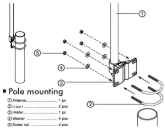
text_image
Pole mounting ① Artenna....1 pc ② U-boit....2 pcs ③ Holder....1 pc ④ Washer....4 pcs ⑤ Screw nut....4 pcsFigure 2-2

text_image
■ Wall mounting ① Antenna....1 pc ② Plastic Fixing ....4 pcs ③ Holder....1 pc ④ Washer ....4 pcs ⑤ Screw ....4 pcsFigure 2-3
- Flat Surface Mount
① "L" bracket.....1 pcs
⑦ Plastic fixing.... 2 pcs
① Screw 2 pcs
④ Antenna 4 pcs
③ "M5" screw, 4 pcs
⑥ Washe.... 4 pcs
⑦ Spring washer.... 4 pcs
⑧ Screw Note 4 pcs
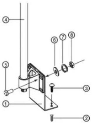
text_image
Technical diagram of a mechanical assembly with numbered components for identificationFigure 2-4
Now, Connect the Antenna
The instructions below cover outdoor and indoor installations.
Connecting the Antenna for and Outdoor Installation
-
Turn off your wireless unit.
-
In the procedure "Pole Mounting Configuration" on page 1-3, the antenna should have been assembled for outdoor installation using the provided 2-meter cable. Connect the other side of the cable to the lighting arrestor as shown here. You can connect the cable to either of the two RF ports on the lightning arrestor.
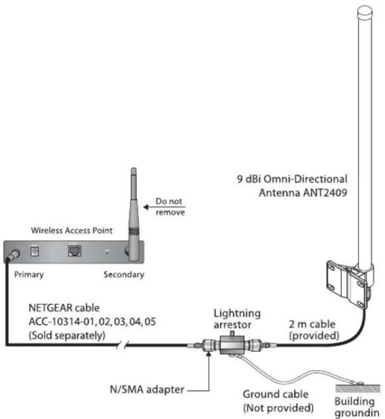
text_image
Wireless Access Point Primary Secondary Do not remove 9 dBi Omni-Directional Antenna ANT2409 NETGEAR cable ACC-10314-01,02,03,04,05 (Sold separately) Lightning arrestor 2 m cable (provided) N/SMA adapter Ground cable (Not provided) Building groundinFigure 2-5
- Connect the grounding cable (not included) from the lightning arrestor to the ground of the building.
Grounding cable: The grounding cable must be equivalent or better than: AWG 10, UL 1015, Stranded, 600 V, 105°C, green or green/yellow insulation, 2 clip of 5.5 mm inner diameter cramped at both ends, cable no longer than 5 meters.

Warning: The lightning arrestor and appropriate ground cable must be used for outdoor installation. NETGEAR does not assume any responsibility in case of hazard resulting of non-compliance with these instructions.
-
Screw the N/SMA Reverse Adapter on the lightning arrestor (clockwise) on the second RF port. Connect a NETGEAR cable model ACC-10314-01, 02, 03, 04 or 05 (sold separately) to the adapter.
-
Locate the primary detachable antenna on the wireless access point. Remove the antenna and connect the other end of the NETGEAR cable ACC-10314-01, 02, 03, 04 or 05 to this port.

Note: On access points with two antennas, if you are only replacing one antenna, be sure to replace the primary antenna and do not remove the secondary antenna
- After attaching your new 9 dBi antenna(s), reconnect your wireless device to the network and turn them on.
Connecting the Antenna for an Indoor Installation
In the procedure “First, Assemble and Mount the Antenna” on page 2-1, the antenna should have been assembled for indoor installation using a NETGEAR cable ACC-10314-01, 02, 03, 04 or 05 and the reverse N/SMA adaptor connected to the antenna. The provided 2m cable should not have been used.
To connect the antenna:
-
Turn off your wireless unit.
-
Locate the primary detachable antenna. Remove the antenna and connect the other end of NETGEAR cable ACC-10314-01, 02, 03, 04 or 05 to this port.
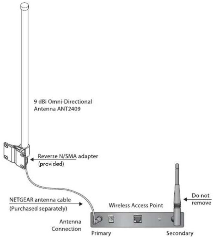
text_image
9 dBi Omni-Directional Antenna ANT2409 Reverse N/SMA adapter (provided) NETGEAR antenna cable (Purchased separately) Antenna Connection Wireless Access Point Primary Secondary Do not removeFigure 2-6

Note: On access points with two antennas, if you are only replacing one antenna, be sure to replace the primary antenna and do not remove the secondary antenna.
- After attaching your new 9dBi antenna, reconnect your wireless device to the network and turn it on.
Chapter 3
Specifications
This chapter provides specifications.
Wireless Antenna and Mounting Assembly
The following table shows specifications for the antenna and mounting assembly.
Table 3-1. Wireless Antenna and Mounting Assembly
| Illustration | Usage Outdoors and | Indoors |
| NETGEAR | Frequency range 2400–2485 MHz | |
| Type Omnidirectional | ||
| Impedance 50 Ohms nominal | ||
| VSWR ≤ 2.0 | ||
| Return loss < –10 dB | ||
| Gain 9 dBi | ||
| Polarization Vertical | ||
| Connector type N Jack Male | ||
| Dimensions 21 mm (0.8 in) max. at antenna baseLength: ~630 mm (25 in) max. for cabling with hardware | ||
| Hardware included 2 U-bolds, 4 screws, 4 plastic fixings, 4 screw nuts, 4 washers | ||
| Antenna color White | ||
| Antenna weight 0.2 kg (0.4 lbs) | ||
| Rust proof Hardware is rust proof. | ||
| Water | Water resistant | |
| UV | UV resistant | |
| Temperature, humidity | -30°C to +80°C (-22°F to 176°F), 20 to 90% RH | |
The following table shows the specifications for the 2 meter antenna cable.
Table 3-2. 2 Meter Antenna Cable
| Specifications | |
 | |
| Frequency range 0–3 GHz | |
| VSWR 1.5: 1 max. | |
| Cable type CFD200 (coaxial cable) | |
| Transmission loss 1.5 dB max. @ 2.4–2.5 GHz | |
| Connector type N plug female* 2 | |
| Max. working voltage 250 Vrms min. | |
| Minimum bend radius 25 mm (1 in) | |
| Jacket PVC | |
| Recommended coupling nut torque 229 | mm.kg* to 559 mm.kg* (4.1 in lbs to 10.0 in lbs) |
| Coupling nut retention force 2.5 kg* (5.5 | lbs) min. |
| Connector body & contact Brass Ni | |
| Insulation | PE |
| Operating temperature/humidity –30°C to 80°C (–22°F to 176°F)/ 20 to 90% RH | |
| Transportation temperature/humidity –40°C to 85°C (–40°F to 185°F)/ 20 to 90% RH | |
| Storage temperature/humidity | –40°C to 85°C (–40°F to 185°F)/ 20 to 90% RH |
| Waterproof | Rain resistant |
| RoHS compliant | Yes |
| UV | UV resistant |
N/SMA Adaptor Accessory
The following table shows the specifications for the N/SMA adapter accessory.
Table 3-3. 2 N/SMA Adapter Accessory
| Illustration Specifications | ||
 | Frequency range 0–3 GHz | |
| VSWR 1.5:1 max. | ||
| Connector type N Plug female to SMA Jack Male | ||
| Insulation resistance 5000 MOhms | ||
| Center contact resistance 6 mOhms | ||
| Outer contact resistance 2 mOhms | ||
| Working voltage 500 V | ||
| Impedance 50 ± 5 Ohm | ||
| Body & center contacts Brass | ||
| Insulation PTFE | ||
| Gasket Silicone Rubber | ||
| Storage & operating temperature | -30°C to +80°C (-22 °F to 176 °F) | |
| Waterproof Rain resistant | ||
| RoHS compliant | Yes | |
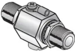
Lightning Arrestor Specifications
The following table lists the specifications for the lightning arrestor.
Table 3-4. Lightning Arrestor
| Illustration Specifications | ||
 | Frequency range 0–6 GHz | |
| VSWR 1.5:1 max. | ||
| Insertion loss 1.3 dB Max | ||
| Impulse breakdown voltage | 110V min. (voltage on upgrade ration @500V/s) | |
| Max. power rating 200 W | ||
| AC current range 20 A at v | voltage release =1S, testing period =5S, testing duration=3 min., per test | |
| Pulse current range 200 A | (at 10/1000us, wave=300, testing duration=3 min., per test | |
| Impedence 50 Ohms | ||
| Insulation resistance 1000 | MOhms | |
| Max. withstanding current | 5000 A, 8/20 μ | |
| Overvoltage protection 90V | min. (100mA, < 150ms) | |
| Connectors N Jack Male *2 | ||
| Color Silver | ||
| Operating temperature -30°C to +80°C (-22 °F to 176 °F) | ||
| Storage temperature -40°C to 85°C (-40°F to 185°F) | ||
| Waterproof Rain resistant | ||
| RoHS compliant | Yes | |
Radiation Patterns
The following illustration shows the radiation pattern for the elevation (vertical plane).

radar
| Angle | Value | |-------|-------| | 0° | -15 | | 30° | -12 | | 60° | -8 | | 90° | -5 | | 120° | -3 | | 150° | -1 | | 180° | -2 | | 210° | -4 | | 240° | -6 | | 270° | -8 | | 300° | -10 | | 330° | -12 | | 360° | -14 | | 390° | -15 | | 420° | -14 | | 450° | -12 | | 480° | -8 | | 510° | -5 | | 540° | -3 | | 570° | -1 | | 600° | 1 | | 630° | 3 | | 660° | 5 | | 690° | 7 | | 720° | 9 | | 750° | 11 | | 780° | 13 | | 810° | 15 | | 840° | 14 | | 870° | 12 | | 900° | 9 | | 930° | 6 | | 960° | 3 | | 990° | 1 |Figure 3-1
The following illustration shows the radiation pattern for the Azimuth (horizontal plane).

radar
| Angle (degrees) | Value | | --------------- | ----- | | 0 | 10 | | 30 | 10 | | 60 | 10 | | 90 | 10 | | 120 | 10 | | 150 | 10 | | 180 | 10 | | 210 | 10 | | 240 | 10 | | 270 | 10 | | 300 | 10 | | 330 | 10 | | 360 | 10 | | 390 | 10 | | 420 | 10 | | 450 | 10 | | 480 | 10 | | 510 | 10 | | 540 | 10 | | 570 | 10 | | 600 | 10 | | 630 | 10 | | 660 | 10 | | 690 | 10 | | 720 | 10 | | 750 | 10 | | 780 | 10 | | 810 | 10 | | 840 | 10 | | 870 | 10 | | 900 | 10 | | 930 | 10 | | 960 | 10 | | 990 | 10 | | 1020 | 10 | | 1050 | 10 | | 1080 | 10 | | 1110 | 10 | | 1140 | 10 | | 1170 | 10 | | 1200 | 10 | | 1230 | 10 | | 1260 | 10 | | 1290 | 10 | | 1320 | 10 | | 1350 | 10 | | 1380 | 10 | | 1410 | 10 | | 1440 | 10 | | 1470 | 10 | | 1500 | 10 | | 1530 | 10 | | 1560 | 10 | | 1590 | 10 | | 1620 | 10 | | 1650 | 10 | | 1680 | 10 | | 1710 | 10 | | 1740 | 10 | | 1770 | 10 | | 1800 | 10 | | 1830 | 10 | | 1860 | 10 | | 1890 | 10 | | 1920 | 10 | | 1950 | 10 | | 1980 | 10 | | 2010 | 10 | | Note: The data is in a single column format. The 'Value' column contains the absolute values of the 'Value' column in the chart. There is no label for the data series. The 'Angle' column is calculated based on the number of angles and is used for plotting the data points on the chart. There is no additional data series present in this case. |Figure 3-2
NETGEAR, Inc.
4500 Great America Parkway
Santa Clara, CA 95054 USA

text_image
Black and white barcode image with vertical lines and a central dot201-11248-01
April 2008