DC130-X - Freezer Bushman - Free user manual and instructions
Find the device manual for free DC130-X Bushman in PDF.

| Product Type | Chest Freezer |
| Capacity | 130 L |
| Dimensions (H x W x D) | 850 x 550 x 550 mm |
| Weight | 30 kg |
| Power Supply | 220-240 V ~ 50 Hz |
| Power Consumption | 120 W |
| Energy Class | A+ |
| Temperature Range | -18°C to -24°C |
| Defrost Type | Manual |
| Noise Level | 42 dB |
| Cooling System | Static |
| Climate Class | SN-T (subnormal to tropical) |
| Refrigerant | R600a |
| Storage Time During Power Failure | 12 hours |
| Freezing Capacity | 10 kg/24h |
| Adjustable Thermostat | Yes |
| Interior Light | No |
| Basket Included | Yes |
| Lock | No |
| Door Switch | No |
| Warranty | 2 years |
| Cleaning Recommendation | Clean with mild detergent and soft cloth |
| Safety Features | Do not store flammable substances; keep ventilation openings clear |
Frequently Asked Questions - DC130-X Bushman
User questions about DC130-X Bushman
0 question about this device. Answer the ones you know or ask your own.
Ask a new question about this device
Download the instructions for your Freezer in PDF format for free! Find your manual DC130-X - Bushman and take your electronic device back in hand. On this page are published all the documents necessary for the use of your device. DC130-X by Bushman.
USER MANUAL DC130-X Bushman
User Manual & Operating Instructions

BUSHMAN

natural_image
Line drawing of an open refrigerator with doors open, showing internal shelves and doorways (no text or symbols)DC-X Fridges
CARAVAN - MARINE - RV - OFFGRID
Congratulations on your purchase of a Bushman DC-X fridge. Please read these instructions carefully before installation and use.
Please be safe and use common sense and caution when installing, operating and cleaning this appliance. If you are unsure about any of these instructions, contact your local stockist before proceeding.
IMPORTANT INFORMATION
Do not lay your fridge on its back, top or sides or at any angle exceeding 30^ . If your fridge has been incorrectly handled, ensure that the fridge is placed in a level upright position for 12 hours to allow the internal fluids to redistribute evenly.
Never operate your fridge directly from a 240 V or AC power supply.
Do not use a modified sine wave inverter to operate your fridge.
PRIOR TO INSTALLATION
DELIVERY
At delivery, please check that the fridge is complete and is not damaged in any way. Remove all packaging and securing tapes from the fridge. To avoid injury and causing damage to the appliance, be extremely cautious when using sharp or pointed tools to complete this task.
Do not connect an appliance that has been damaged, contact your local dealer immediately.
INSTALLATION
Installation of the DC-X range of fridges must be completed by a suitably trained professional only.
POWER SUPPLY
Your fridge must be connected to a stable and regulated 12 V or 24 V DC power supply only. The compressor will automatically detect which voltage is present adjust accordingly.
If you are using a generator or other power supply, the output must be a pure sine wave. Any fluctuations in generator current may damage the compressor.
WIRING
For optimum results, you will need the correct sized wire depending on the distance from your power supply to the fridge. Wiring must be directly from your fridge to your battery and should be continuous without joins. Please also ensure the earth is wired directly to your battery, not to a chasse. If your wiring is insufficient, your fridge may not perform correctly or may be even be damaged.
| CROSS SECTIONIN MM2 | MAXIMUM LENGTH OF WIRE IN METRES | |
| 12 V | 24 V | |
| 2.5 | 2.5 | 6 |
| 4 | 4 | 8 |
| 6 | 6 | 12 |
| 10 | 10 | 20 |
Any switches must have a breaking load not less than 20 A on 12 V or 10 A on 24 V.
The power supply wiring must also be protected with a 15 A fuse.
Ensure sure the wiring polarity is correct. Connect the red wire to the positive terminal (+) and the black wire to the negative terminal (-).
Never connect bare electric wires. Use only connections of a size suitable for the cross section of the wire being used.
INSTALLATION INTO A CAVITY
DC-X fridges are designed to be installed in a cavity. A gap of minimum 40mm is recommended for the rear. Refer to the following table for the recommended cut-out dimensions. If you are using the mounting kit, allow an extra 5mm width for the mounting kit frame and screws.
| MODEL | CUT-OUT CAVITY DIMENSIONS (MM) | ||
| WIDTH | DEPTH | HEIGHT | |
| DC50-X | 385 | 495 | 530 |
| DC65-X | 455 | 515 | 530 |
| DC85-X | 480 | 550 | 630 |
| DC130-X | 530 | 550 | 755 |
EFFICIENT OPERATION
VENTILATION
Ventilation will have a significant impact on the efficient operation of your fridge. A minimum of 2 vents need to be provided from the rear of the fridge cavity to the outside environment, or to the general area where the fridge is located. The vents should be located at the bottom and top of the fridge cavity and have a free cross section of minimum 200cm2 each. By providing free air flow to the compressor area your cooling system will remove heat faster and the fridge will operate more efficiently.
MOUNTING KIT
The mounting kit is first affixed to the side and top of the fridge cabinet using the screws provided.
Once the fridge has been connected to the power supply and moved into its final position, the mounting kit can be affixed to the front of the cavity.
• Turn the thermostat knob around from 0 to power up the fridge.
• The cooling level can be set between 1 and 7.
- 7 is the coldest setting and 1 is the warmest.
EQUALISING THE FRIDGE
During the first 24 hours of operation, your compressor will operate for longer than usual. This process allows the internal air temperature, food, drinks, condenser and insulation to equalise.
ENERGY SAVING TIPS
- Have a much ventilation as possible – the more the better.
- Keep the fridge out of direct sunlight whenever possible
• Only open the fridge or freezer door when necessary - Allow hot food to cool down before placing inside the fridge
• Defrost the fridge as soon as a layer of ice forms - Set the fridge to be only as cold as necessary
USING THE FRIDGE IN EXTREME HEAT
If you are using your fridge in a very hot area or situation, removing the drip tray will improve cold air circulation throughout the fridge cabinet. Note the DC130-X models do not have a drip tray.
CLEANING
Wash the inside of your fridge with luke warm water and a mild soap. Never use abrasive or corrosive cleaning agents, steel wool or scouring sponges. A soft sponge, towel, or soft brush is recommended.
Always keep the inside of the fridge clean and dry. Remove any condensate water or ice which gathers in or near the tray under the freezer compartment.
Be careful when opening or closing the freezer door if ice has been allowed to accumulate in this area.
Keep the door of the fridge ajar when the fridge is not in use, to allow fresh air to circulate inside the fridge compartment.
DEFROSTING
Defrosting needs to be carried out when the ice layer reaches a thickness of 5mm.
Set the thermostat to 0 and move your food and beverages to another cool place. Do not use any objects to remove the ice or frost, it must be allowed to melt naturally. Once the ice has melted, dry the inside of the fridge and freezer compartment.
MOVING THE DOOR HINGES TO THE LEFT-HAND SIDE
To change the hinge side, unscrew the door hinges from the fridge cabinet, move to the other side and re-affix using the same screws. There is a black washer on the bottom hinge, this must stay in place.
MOVING THE DOOR HANDLE
- Remove the 2 screws which hold the door handle in place. Access is provided under the logo sticker. You can more easily remove the sticker by applying moderate heat from a hair dryer.
- Gently lift the door handle off.
- Reposition the door handle on the preferred side.
- Drill 2 small (2mm) pilot holes through the door handle for the original screws.
- Reaffix the door handle using the original screws.
- Reapply the logo sticker onto the door handle by applying moderate heat to the sticker.
- Use the supplied DC-X Series sticker to cover the old screw holes.
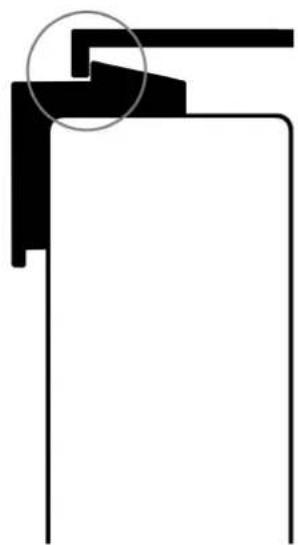
- Check that the plastic door latch is flush with the top metal rail when the door is closed. If there is more than 1-2mm of movement, you will need to adjust the position of the top metal rail. To do this, unscrew the top metal rail and move it backwards so that the plastic latch is just touching. Reaffix in this position. See diagram below:
CORRECT 0-1MM GAP
natural_image
Pure geometric line drawing with no text, numbers, or symbolsINCORRECT 2MM+ GAP

natural_image
Pure geometric line drawing with no text, numbers, or symbolsRUBBER SEALS
- There are magnets inside the rubber seal which pull towards the metal fridge cabinet to keep it airtight.
- After you have adjusted your door latch, check to see that the rubber seal is making contact with the fridge cabinet on all 4 sides. If there is even a small gap, this will affect the performance of your fridge.
- Starting from a corner, gently heat up the rubber seal with a hair dryer or light heat from a heat gun (be careful not to overheat the rubber or it will melt). As the rubber heats up, the magnets inside will pull the seal towards the fridge cabinet. Slowly work your way along the rubber from one corner to the other until it is fully sealed.
REPLACING THE FRONT DOOR PANEL
- Follow steps 1 to 2 under "Moving the door handle" above.
- Gently remove the bottom door profile which supports the door panel. Using a screwdriver gently lever the bottom door profile outwards only. Do not lever it down.
- Gently slide the original door panel down and out of the door.
- Slide the new door panel upwards and into place.
- Reposition the bottom door profile to be flush.
- Continue from steps 3 to 6 under "Moving the door handle" above.
TROUBLE SHOOTING
VOLTAGE
The most common cause of an incorrectly functioning fridge is a lack of voltage.
Your fridge has built in battery protection and needs the following minimum voltage for the compressor to start (Cut-in) or stop (Cut-out).
Battery Protection Settings
| VOLTAGE | CUT OUT | CUT IN |
| 12 V | 9.5 V | 11 V |
| 24 V | 21 V | 23V |
During fridge operation, a load is placed on your power supply which can cause your supplied voltage level to drop by as much as 2 – 3V. This occurs especially if the wiring in insufficient or if there is a loose connection.
If this occurs, your fridge may exhibit a continuous start / stop / start pattern. If so, have your wiring checked by an electrician when under a 10 A load.
TROUBLESHOOTING
Check:
- Correct power supply
- The voltage to the compressor is still 12V when a 10 A load is placed on the wire
- The fan is operating
• The polarity of the connections are correct
• There is adequate ventilation to the rear of the fridge - The fuse is not blown
- The rubber door seal is touching the fridge cabinet all the way around on all 4 sides
• The door latch has a tight fit when closed - You have given the fridge enough time to cool down
TECHNICAL SPECIFICATIONS
| DC50-X | DC65-X | DC85-X | DC130-X | |
| COMPRESSOR | Secop | Secop | Secop | Secop |
| BD35 | BD35 | BD35 | BD35 | |
| VOLTAGE | 12 V / 24 V | 12 V / 24 V | 12 V / 24 V | 12 V / 24 V |
| DC | DC | DC | DC | |
| WATT RATING | 60 W | 60 W | 60 W | 60 W |
| EXTERNAL | W 380 | W 450 | W 475 | W 525 |
| DIMENSIONS(mm) | D 495 | D 515 | D 550 | D 550 |
| H 525 | H 525 | H 625 | H 750 | |
| NETT WEIGHT | 16.4 kg | 18 kg | 22.5 kg | 27.2 kg |

text_image
380 160 140 525 365 110 385 60 445 50 20MODEL: DC50-X
MOUNTING KIT
COOLING UNIT
SCALE: (MM)
text_image
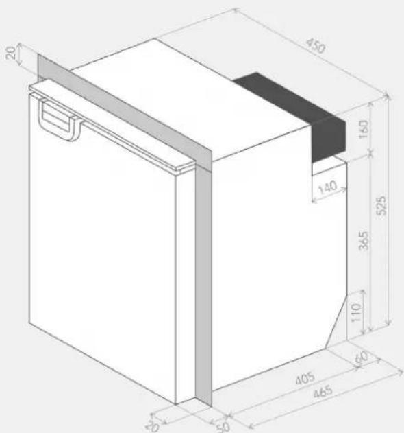
20 450 160 140 365 525 110 405 60 465 80 50MODEL: DC65-X
MOUNTING KIT
COOLING UNIT
SCALE: (MM)

text_image
MODEL: DC85-X MOUNTING KITMOUNTING KIT
COOLING UNIT
SCALE: (MM)
text_image
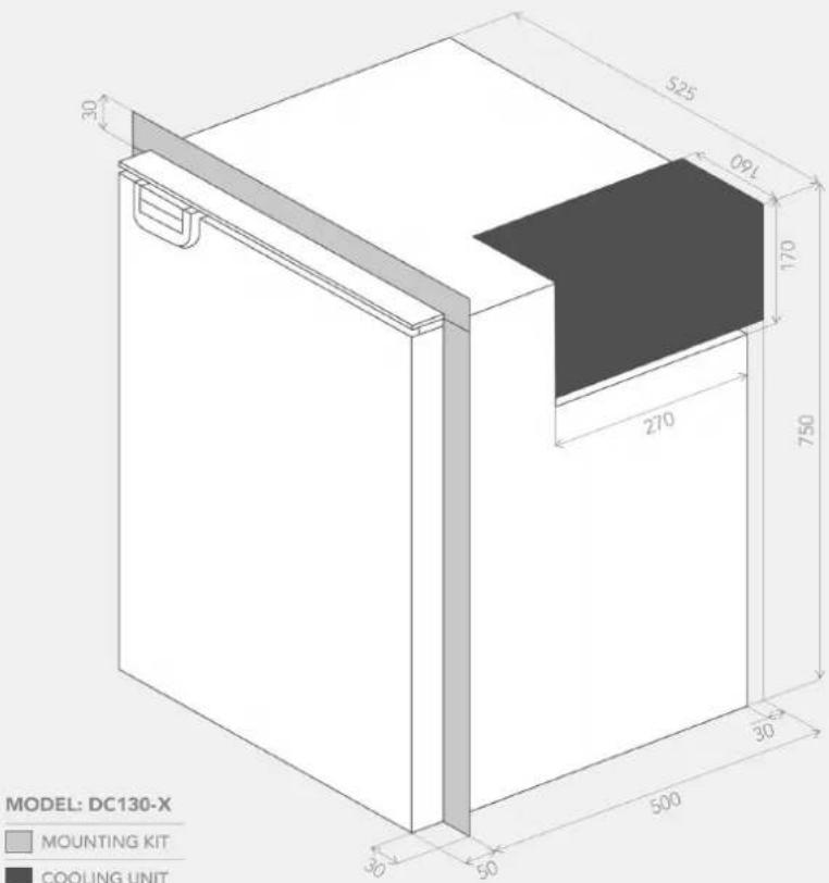
MODEL: DC130-X MOUNTING KIT COOLING UNITMOUNTING KIT
COOLING UNIT
SCALE: (MM)
VENTILLATION OPTIONS DC-X

text_image
min 200cm²▲ Exterior Ventilation
text_image
min 40mm min 40mm min 40mm
text_image
min 150mm▲ Interior Ventilation Option 1
▲ Interior Ventilation Option 2

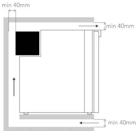
text_image
min 40mm ↑ ← min 40mm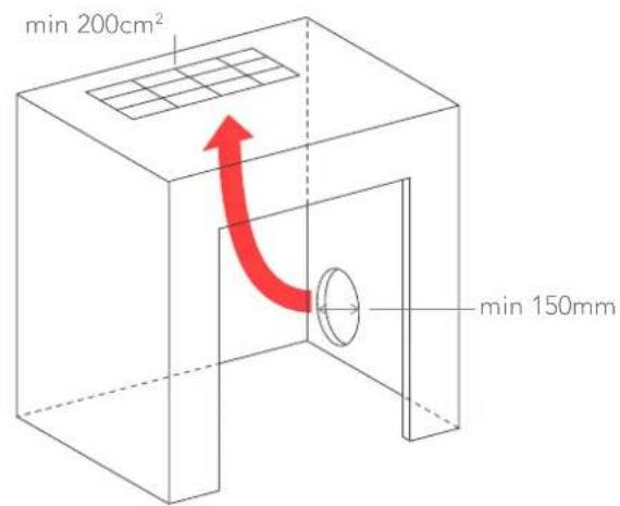
text_image
min 200cm² min 150mm▲ Interior Ventilation Option 3
▲ Interior Ventilation Option 4
NOTES
WARRANTY
DP Refrigeration Pty Ltd trading as Bushman Fridges ABN 94 615 295 255 (Bushman) warrants, to the original owner, that this product is free from defects in workmanship and material for a period of three (3) years from the purchase date. This warranty shall be limited to repairing or replacing, at Bushman's option and without charge to the purchaser, defective components. All warranty work shall be performed at a Bushman approved facility. Shipping charges related to returning the product to the Bushman facility are not covered under this warranty. However, this warranty covers shipping charges related to returning the repaired product to the customer. This warranty does not apply to damage or wear to the product caused by accident, abuse, misuse, neglect, unauthorized alteration or repair, or if the product was not used in accordance with Bushman printed installation and operating instructions. To obtain service under this warranty, the defective product must be returned to Bushman together with a copy of the original purchase receipt. Any product repaired or replaced under this warranty will be warranted for the balance of the warranty period with respect to the original purchased product. Bushman is not liable for any incidental or consequential loss or damages whatsoever as a result of use or misuse of this product. Any statutory warranty also applies.

BUSHMAN
For after sales service and enquiries, please contact: