95 (1961) - Car SAAB - Free user manual and instructions
Find the device manual for free 95 (1961) SAAB in PDF.

User questions about 95 (1961) SAAB
0 question about this device. Answer the ones you know or ask your own.
Ask a new question about this device
Download the instructions for your Car in PDF format for free! Find your manual 95 (1961) - SAAB and take your electronic device back in hand. On this page are published all the documents necessary for the use of your device. 95 (1961) by SAAB.
USER MANUAL 95 (1961) SAAB
natural_image
Line drawing of a vintage car with open windows and wheels, shown from front and side views (no text or symbols)owner's manual
OWING AUTO SALES
Lincoln St. - Rt. 3A
Hitcham, Mass.
Riverview·P-1617
SAAB [15]
owner's manual
78 78 61
SAAB
SVENSKA AEROPLAN AKTIEBOLAGET
TROLLHÄTTAN
SWEDEN
BOHUSLÄNS GRATISKA AB - UDDEV - LLA
face
Saab Oner,
is a great pleasure to present you with this manual for your Saab 95.
The Saab 95 is a high quality estate-car, manufactured to fulfill the greatest demands regarding quality and performance.
However, no car will give proper satisfaction if not correctly maintained, no matter how well it is designed and manufactured. Faulty driving technique and neglected maintenance will spoil the good qualities of the car and shorten its life. Particularly while the car is new, it needs regular inspection and service by trained experts. By reading this booklet and keeping it conveniently accessible, you will become familiar with your car and its qualities and you will also be able to ensure that it receives all the care it needs. The contents do not involve any obligations concerning the equipment of the car, which may be subjected to modifications during the series production.
The first section of the manual, "Technical Data", is a summary of specifications and performances. The second part, "Description", provides brief information about the construction of the car, its various systems and equipment. The third section, "Operation and Maintenance" — the most important part — includes instructions for running-in, general driving hints and directions regarding the care and maintenance of the car. Since some of the maintenance operations described are very important, it is recommended that they be carried out preferably by an approved service garage.
We are convinced that the contents of this booklet will be of benefit for your car, and that your Saab 95 will give you the profit and pleasure expected from it.
Trollhättan in March 1961.
SVENSKA AEROPLAN AKTIEBOLAGET

text_image
SPAGIntroducing the SWEDISH AIRCRAFT COMPANY
Formed originally in 1937 to manufacture airplanes, the Swedish Aircraft Co. Ltd. — SAAB — has since World War II also become a major producer of automobiles.
SAAB began automobile production in 1949—50 with a four-passenger two-cylinder car — the Saab 92 — which rapidly gained popularity for its rugged design, excellent economy and outstanding driving characteristics. In 1956 the Saab 92 was replaced in production by a new model, the threecylinder Saab 93, which quickly became a real best-seller, not only in the highly competitive Swedish market, but also in the export markets. Its outstanding qualities have been proved by overall victories in several international car rallies, including the 4th Annual Great American Mountain Rallye in 1956. The Saab 93 also won the European Rallye Championship in 1957.
In 1959 a station wagon, the Saab 95, appeared on the market and in the spring of 1960 a new standard model the Saab 96 was introduced. Featuring numerous improvements the Saab 96 represents the greatest change that the Saab car has undergone since the 93 model was introduced. The most noticeable change is the completely new rear end with the much larger rear window.
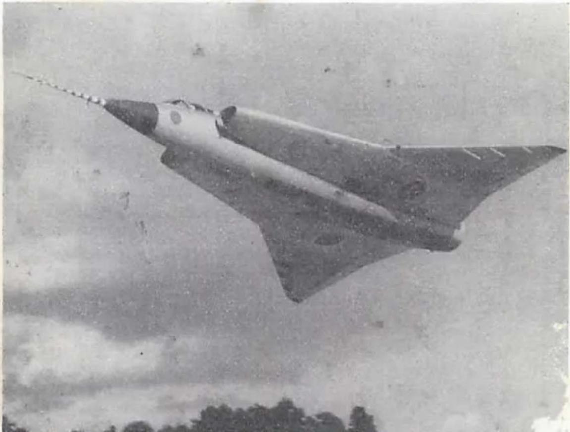
The Swedish Aircraft Co. Ltd. is today the largest privately-owned airplane manufacturer on the European continent, employing in its own factories more than 9,000 people. It supplies most of the aircrafts used by the Swedish Air Force, and is well known in international aviation circles for the modernity of its airplanes. In 1951 SAAB started delivering the Saab 29, the first swept-wing jet fighter in service in Western Europe. The company has also supplied the Swedish Air Force with large quantities of the Saab 32 "Lansen", a two-seat radar-equipped allweather attack, fighter and reconnaissance airplane, which can attain supersonic diving speed. Another well-known aircraft is the Saab 91 "Safir", which is being used in many countries for military and commercial pilot training.
Late in 1955 another SAAB combat airplane made its first flight, spectacular Saab 35 "Draken", single-seat, allweather fighter. Featuring a special type of delta wing called the "double delta", developed exclusively in Sweden, the Saab 35 has a top speed of

text_image
SAABmore than twice the speed of sound and a phenomenal rate of climb. This highly advanced fighter has now gone into service with the Swedish Air Force.
SAAB today operates four major plants in addition to a number of smaller factories. The main plant and the center of airplane development and production is at Linköping. The three other major plants are situated at Trollhättan (motorcars and jet engine parts), Gothenburg (motorcar power units etc.) and Jönköping (airplane and missile equipment etc.) A helicopter division is situated at Norrköping.
natural_image
Black-and-white photo of a missile in flight against a cloudy sky (no visible text or markings)The Saab 35 Draken is one of the world's most modern interceptor fighters. Top speed exceeds 1,200 mph.
Index
| Technical Data page | Description page | Operation and Maintenance page | |
| Engine | 8 | 12 | 28, 32 |
| Fuel System | 8 | 14 | 32 |
| Cooling System | 8 | 14 | 35 |
| Transmission | 8 | 16 | 26, 37 |
| Suspension | 9 | 16 | 38 |
| Brake System | 9 | 18 | 27, 38 |
| Steering Mechanism | 9 | 18 | 25, 30 |
| Wheels and Tires | 9 | 41 | |
| Instruments, Controls and Equipment | — | 19 | 27 |
| Electrical System | 10 | 22 | 44 |
Driving Instructions 25,30
Useful Hints 31
Trouble Shooting 54
Optional Extras 57
Lubrication Directions 61
The following operations are described:
Carburetor, idling adjustment 33
Fuel Pump, checking and adjustment of breaker points ..... 34
Clutch Pedal, adjusting play 37
* Bleeding of Brake System 39
* Brake Adjustments 39
Fan Belt, adjustment of tightness 45
* Ignition Distributor, checking breaker points and gap ..... 46
* Ignition Timing 47
* Aiming Headlights 49
Bulb Replacements 52
Fuse Replacement 53
SAB 95B
Technical Data
General
Overall length; including bumpers ...
Overall width ....
Overall height, empty ....
Road clearance (2 passengers) .....
Track, front and rear ....
Wheelbase....
Turning radius ....
Hill climbing performance
1st speed
2nd speed
3rd speed
4th speed ....
Reverse
Empty weight, excl. fuel and water ..
Empty weight, incl. fuel, water, tools and spare wheel....
Weight distribution Empty ...... Fully loaded, incl. 7 pass. 1480 kg (3265 lbs.) ....
Loading capacity with 1 pass.
with 2 pass.
with 5 pass.
Height of loading space ....
approx. 4120 mm (13 ft. 6 in.)
1570 mm ( 5 ft. 2 in.)
approx. 1470 mm (4 ft. 10 in.)
approx. 190 mm (7.5 in.)
1220 mm (4 ft.)
2488 mm (8 ft. 2 in.)
approx. 5.5 m (18 ft.)
| 4-speed | 3-speed |
| 40 % | 34 % |
| 23 % | 16 % |
| 13 % | 9 % |
| 7 % | — |
| 37 % | 41 % |
approx. 860 kg (1895 lbs.)
approx. 900 kg (1985 lbs.)
front 54 %
front 48 %
1600×950 mm (63×37 in.)
510 kg (1125 lbs.)
1600×950 mm (63×37 in.)
425 kg (940 lbs.)
1000×950 mm (39×37 in.)
170 kg (375 lbs.)
800 mm (32 in.)
Engine
Type two-stroke, three
cylinders in line
Power
SAE at 5000 rpm 42 bhp
DIN at 250 rpm 38 bhp
May. for at 30' pinn 8.2 kpm (59 ft.-lbs)
Cyli er time, total 841 cc (51.9 cu.in.)
Bor of 1 and s 70 mm (2.76 in.)
73 mm (2.87 in.)
on ratio, nominal 7.3:1
stem
el tank capacity .... approx. 43 liters (11.5 US gal.)
Carburetor, down-draft type .... Solex, type 40 AI
Fuel pump, electric SU, type AUA 79
Cooling System
Ce city, incl. heater .... approx. 7.5 liters (2 US gal.)
Ten. erature, normal .... approx. 90° C (195° F)
Ther stat, opens at approx. 85°C (185°F)
Transmission
Oil facility, gearbox with differential approx. 2 liters (2 US qts.)
Clut..... single dry plate with
cushioning device
Plat meter, outer 180 mm (7 in.)
Gear ratios, total 4-speed 3-speed
1st speed 19.3:1 17.2:1
2nd speed 11.4:1 8.5:1
3rd speed 7.0:1 5.3:1
4th speed 4.6:1
Reverse 15.2:1 21.0:1
Differential gear ratio 5.43:1
Road speed at 1000 rpm engine speed.
3-speed
1st speed 6.8 km/h (4.2 mph)
2nd speed 13.6 km/h (8.4 mph)
3rd speed 22.4 Lm/h (13.8 mph)
Reverse 5.5 km/h (3.4 mph)
4-speed
1st speed ..... 6.0 km/h (3.7 mph)
2nd speed ..... 10.3 km/h (6.4 mph)
3rd speed.... 16.8 km/h (10.4 mph)
4th speed 255 km/h (15.8 mph)
Reverse 7.3 km/h (4.5 mph)
Suspens
Maximum sl.
Front wheel.
Rear wheels . .
Shock absorbers, fr
rear
ic-arm shoe
Maximum stroke, front w. 2 mm (3.2 in.)
rear wheels 3 mm (4.4 in.)
Brake System
Foot brake, four-wheel ...... Lockheed, hyd .ulic
Parking brake, rear wheels .... me' inical
Brake lining sizes:
Front 13/4
Rear 8 1/2"
Total area 675 cm² (105 in.)
Steering Mechanism
Steering gear ratio, steering wheel/road wheels average 14:1
Number of turns, lock to lock .... 21/4
Wheels and Tires
Type wide base, disc wheels
Rim dimensions 4J×15"
Tire pressure: kp/cm² Front 5.60 × 15"
Tire dimensions 1.4—1.6
Rear 1.4—1.8
(lbs/sq..n.) Front 20—23
Rear 20—26
Electrical System
Voltage 12 volts
Battery acity 33 amp/h
St. 0.5 hp
Generator 160 watts
Spark plugs:
ead M 18
read length 12 mm (0.5 in.)
Electrode gap 0.7 mm (.028 in.)
Heat range:
Ordinary driving and running-in ... Champion UK 10,
(Hot plug.) or equivalent
Fast driving (exceptionally) .... Bosch M 225 T1
(Cold plug.) or equivalent
Ignition timing at 3000 rpm 20° before T.D.C.
Timing, advance weights retracted .... 10° before T.D.C.
Breaker point gap, distributor .... 0.3-0.4 mm (.012-.016 in.)
Firing sequence (No. 1 is the rear cyl.) 1—2—3
BULBS and FUSES
Sealed Beam (U.S.A.) 50/40
Headlights (R.H.D.) 12620 45/40
License plate lights, 2 12844 5
Turn and parking lights, front, 2 ..... 1034 20/5
Parking lights, rear, 2 12821 5
Turn and stop lights, rear, 2 ..... 1073 18
Instrument light and control lights, 5 12913 2
Courtesy lights, 2 12844 5
10 + 2 fuses, 25 mm (1 in.) ....8' amp
Tools
Jack and ratchet wrench in bag
Tool bag, containing:
1 Spark plug/wheel bolt wrench (socket and pin)
1 Adjustable wrench
2 Fixed wrenches
1 Combination pliers
2 Screwdrivers
1 Square key for transmission filler, drain and inspection plugs
natural_image
Side profile sketch of a vintage car with front wheel and side panel (no text or symbols)
natural_image
Top-down line drawing of a car viewed from the side, showing front and rear views with no text or symbols.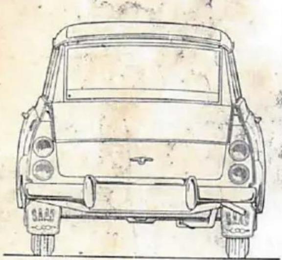
natural_image
Front view line drawing of a vintage car with visible headlights and front wheels (no text or symbols)
natural_image
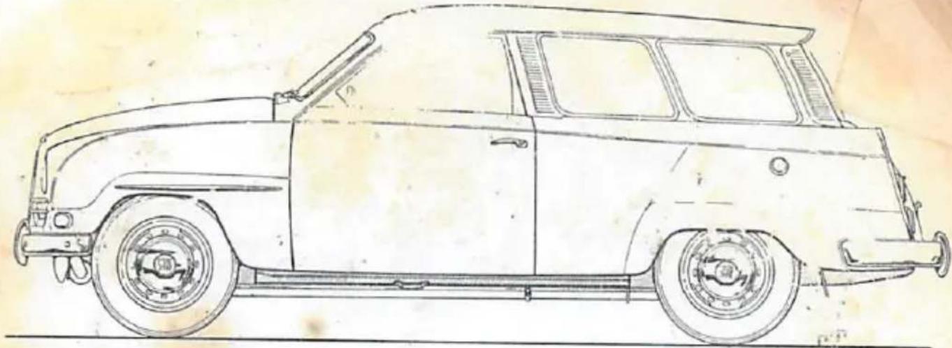
Front view line drawing of a classic car with front grille and grille grilles (no text or symbols)Fig. 1. Four-view drawing
text_image
SAAB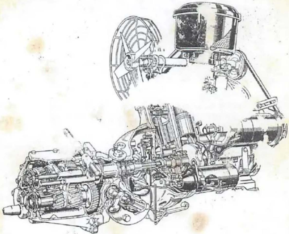
natural_image
Technical line drawing of a mechanical assembly, showing internal gears and shafts (no text or labels)Fig. 4. Engine, sectioned
The cylinder block is integral with the upper part of the crankcase and with the lower crankcase half. These two parts are iron castings while cylinder head and piston. I aluminum alloy.
The crankshaft is supported in the crankcase by four ring bal bearings, and the big-end bearings of the piston rod roller bearings. Since the crankshaft is built-up of disk nected with main and big-end bearing pins with very close special precision tools, it should be recondition the manufacturer.
The engine and the transmission are bolted together with a unit, which is supported on three rub or he lifted out very easily either separately
Cooling System
The capacity of the cooling system, including the heater element, is approx. 7.5 liters (2 US gal.). The main parts of the system are radiator, thermostat and pump. Before the engine has reached its proper operating temperature, the radiator inlet hose is closed by the thermostat. The coolant flows through a by-pass until it has reached a temperature of approx. 85°C (185°F), when the thermostat opens. The fan is driven by a V-belt and the coolant pump impeller is attached to the generator shaft extension.
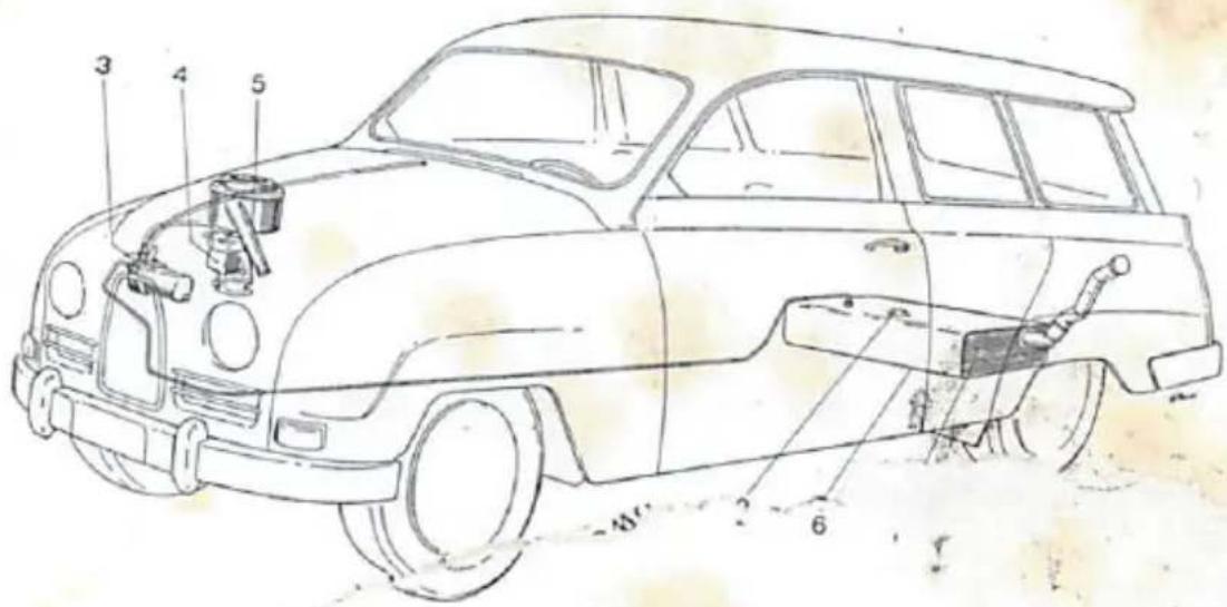
Fuel System
The fuel tank with built-in mixer is located under the luggage compartment floor panel and has approx. 43 lit. (11,5 US gal.) capacity. From the tank the fuel runs in a pipe via the electric fuel pump and through a flexible pipe up to the carburetor. There are two fuel filters, one inside the banjo fitting at the carburetor, fig. 17, and one in the pump fig. 18.
text_image
Technical diagram of a vintage car with numbered parts for identificationFig. 5. Fuel System
- Fuel tank with mixer
- fuel gauge, tank unit
-
Fuel pump
-
Carburetor, Solex 40 AI
-
Suction silencer with filter
-
Drain plug (under the car)
Air Filter
The suction silencer containing the air filter element is secured on top of the carburetor by a clamp screw and to the fan shaft stand by a bracket. The air intake pipe may be extended for collecting heated air at the exhaust manifold, see fig. 16.
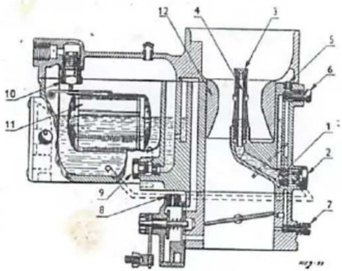
Carburetor
text_image
Technical diagram of a mechanical device with numbered components for identificationFig. 6. Carburetor, Solex 40 AI
- Main jet 7. Idling air adjustment screw
- Main jet carrier 8. Starting air jet
- Emulsion jet 9. Starting jet
- Emulsion pipe 10. Needle valve
- Idling air jet 11. Float
- Idling jet 12. Air throat
Adjustments of the down-draft Solex 40 AI carburetor should be carried out only by experienced mechanics. The following figures give the nominal choke and jet sizes and numbers refer to fig. 6:
Air throat, 12 28 mm (1.1 in.)
Main system:
Main jet, 1 135
Emulsion jet, 3 250
Emulsion pipe, 4 1
Idling system:
Air jet, 5 100
Fuel jet, 6 45
Cold start system:
Air jet, 8 3.5
Fuel jet, 9 190
Transmission
The transmission housing has three compartments, the rear one containing shafts, gears, shift forks, etc. constituting the gearbox. The center part contains free wheel device and pinion/ring gear with differential, to which the drive shafts are connected. The front part of the housing is limited by the engine and covers the release bearing and the clutch.

text_image
Technical diagram of a mechanical device with numbered components labeled 2 and 3Fig. 7. Transmission plugs
- Filler plug
- Level plug
- Drain plug
The Saab 95 may be equipped with either three speed or four speed gearbox. They both have helical gears in constant mesh, which are locked to their shafts by coupling sleeves. In the three speed gearbox 2nd and 3rd gears are synchronized and the coupling sleeve for the first gear is integral with the sliding reverse gear pinion. In the four speed gearbox all forward speeds are synchronized. The free wheel device between clutch shaft and gearbox is operated from the driver's seat.
For gear shifting and free wheel operation instructions, see page 26.
Suspension
The Saab 95 has coil spring suspension at the front as well as at the rear. Rubber bushings are used extensively to minimize road noise and reduce the number of lubrication points. The suspension, fig. 8, consists of two separate front axle units and one rigid rear axle.

The front wheels are independently suspended and each front axle is mounted by ball joints to one upper and one lower transverse spring arm. Each one of these wishbone spring arms is attached to the body brackets by rubber bushings. A coil spring is installed between a seat on the upper spring arm and a similar one in the body. The spring arm deflections are limited by rubber bumpers.

natural_image
Line drawing of a vintage car showing internal components including suspension springs, drivetrain, and suspension frame (no text or labels)Fig. 8. Axles and Suspension
The rear wheels are carried on spindles fitted in the swept-back ends of the rigid, U-shaped axle, which is mounted in a recess under the body by a central rubber bushing and braced by two longitudinal side links. The coil springs are installed between seats in the body and on the inner extensions of the wheel spindles.
Rubber bumpers and straps limit the upward and downward deflections respectively.
Shock Absorbers
The double-acting, hydraulic-telescopic shock absorbers of the front suspension are rubber mounted to the lower spring arms. The rear suspension has double-acting arm shocks, which are mounted to the body, and the arm is attached to the rear axle via a connecting rod.

text_image
SAAB
Bra.
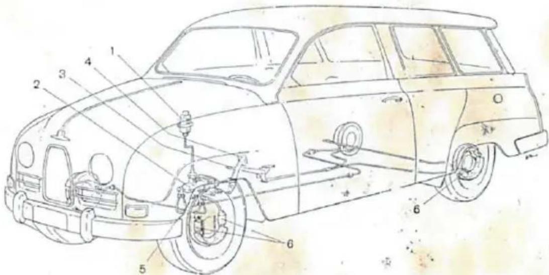
The brake acts on all four wheels. A rear wheel has one double cylinder and a front wheel has two single-acting ones. The fluid container is located in the engine compartment to the radiator, and below the container stop light switch is fitted to the wheel housing panel.
The parking brake is mechanical and works on the rear wheels only. The brake lever is placed between the front seats and is connected to the rear wheel cylinders by two Bowden cables.
text_image
Technical diagram of a car with numbered parts for identification and assembly referenceFig. 9. Brake System
- Brake fluid reservoir 4. Brake pedal
- Master cylinder 5. Stop light switch
- Hand brake lever 6. Wheel cylinders
Steering Mechanism
The steering movement is transmitted from a pinion at the end of the steering tube to a transverse rack, the ends of which are connected to the steering arms by adjustable drag rods of equal length. The drag rods are attached to rack and steering arms by adjustable ball joints and drag rod ends respectively.
NOTE. All adjustments of the steering gear should be carried out by an authorized Saab service shop.

text_image
Technical line drawing of a vintage car with numbered parts for identification
text_image
Technical diagram of a mechanical assembly with numbered parts, showing cross-sectional and top views.Fig. 10. Steering Mechanism
-
Steering gear
-
Steering tube pinion
-
Inner ball joint
-
Rack
-
Outer ball joint
-
Rack damper, spring and plunger
-
Spindle housing
-
Drag rod
Instruments, Controls and Equipment
- Cold start control. For operation see page 27.
- Air temperature and defroster controls, see fig. 33.
- Fan motor switch, see fig. 33.
- Instrument light intensity control, when the lights are on.
- Light switch. On pulling out the knob to first position the parking lamps will be lighted, in the second position the headlights.
- Instrument unit, see fig. 12.
- Hood lock lever.
- Ignition and starter switch (thief-proof). — Integral with ignition coil.

text_image
Technical diagram of a car interior with numbered components for identificationFig. 11. Instruments and Controls
- Windshield wiper switch and pump for windshield washer. The wipers are started by turning the knob. On pulling out the knob the pump will start working.
- Ashtray. A second one is provided for the rear seat.
- Gear shift lever. Regarding gear shift positions, see fig. 15.
-
Glove compartment with lid. Radio installation is possible by removing the detachable panel in the lid.
-
Turn indicator switch.
- Grill screen control.
- Free wheel control. The free wheel is locked by pulling out the handle entirely, see page 26.
- Headlight dip switch, main and low beam.
- Brake lever.
- Seat adjustment mechanism. When the lever is depressed, the seats are unlocked for longitudinal adjustment.
- Mechanism for adjusting the seat back inclination.
The ventilator lever, which is not visible on the fig., is located under the instrument panel behind the ash tray.

text_image
0 20,40 60 80 100 120 140 1 57242 7 6 5 4 3 2Fig. 12. Instrument Unit
The instruments are placed in a panel in front of the driver and are easily visible through the duo-spoked steering wheel.
-
Speedometer and mileage recorder. The speedometer, graduated from 0 to 140 km/h (90 mph), is actuated via a flexible shaft by a worm gear on the pinion shaft of the gearbox. The mileage recorder is driven from the same shaft as the speedometer. The mileage is registered in full kilometers (miles).
-
Clock.
- The ammeter shows charging or discharging current of battery.
- Control lamp for turn indicators flashing a green light when the indicators are operating.

- Headlight or is on.
- The fuel level indicates the fuel level in the tank when the igni+ switch on. A warning light comes on when about 7 li U.S. of fuel remain.
- T1-nometer indicates the coolant temperature in C° (F°). normal driving conditions the temperature should be about 0°C (95°F), i.e. rather high on the green part of the scale.
Electrical System
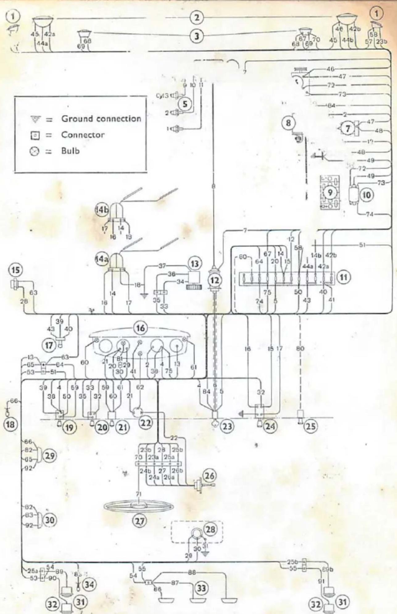
The electric system is shown schematically in the adjacent wiring diagram. In order to facilitate service and maintenance the various cables have different insulation colors as per the following table:
Black: 1, 7, 18, 19, 23a, 24a, 32, 37, 45, 46, 47, 48, 49; 71, 77, 78, 79, 80.
Red: 2, 5, 8, 9, 10, 11, 14, 15, 20, 21, 27, 28, 33, 34, 39, 63, 65, 67, 68, 72, 92.
Green: 16, 22, 50, 51, 52, 53, 54, 55, 56, 57, 58, 59, 60, 61, 86, 87, 88, 90, 91.
Grey: 4, 12, 13, 25b, 26b, 29, 35, 36, 38, 44a, 62, 64, 69, 70; 74, 75, 76.
White: 23b, 24b, 40, 41, 42b.
Yellow: 17, 25a, 26a, 30, 43, 44b, 66, 73, 81, 82, 83, 84, 89a, 89b.
Blue: 42a.
Explanations to the encircled numbers of Fig. 13.
- Turn signals and parking lamps
- Door-contact for courtesy light
- Light switch (headlights)
- Headlights
- Heater fan switch
- Horns 21. Instrument light switch
- Distributor 22. Flasher
- Spark plugs 23. Ignition and starter switch
- Generator (thief-proof)
- Fuel pump 24. Wiper switch
- Starter 25. Cigar lighter
- Battery 26. Turn signals switch
- Relay 27. Wheel with horn button
- Fuse box 28. Tank unit, fuel gauge
- Ignition coil 29. Courtesy light with switch
- Heater fan motor 30. Courtesy light
- Wiper motor 31. Stop lights and turn signal
- Stop light switch 32. Parking lamps
- Instrument unit 33. Licence plate lights
text_image
1 45 42a 44a 68 69 ② ③ 67 70 68 69 46 42b 45 44b 58 23b = Ground connection = Connector = Bulb ① ⑤ Cy13 2 1 46 47 72 73 84 2 7 47 48 -1? -48 -49 72 -49 73 ⑧ ⑨ 10 74 15 63 14b 17 14 19 14a 14 18- 37 36 34 12 7 12 58 14b 42b 80 67 14 15 44a 42a 75 50 43 41 11 51 60 16 15 17 80 32 39 4 59 33 59 61 62 38 50 35 32 60 21 19 20 21 22 23 b 28 25b 23 a 25a 24 b 27 26b 24 a 26a 70 71 26 27 28 30 31 25b 55 80b 91 32 31 34 54 88 86 87 33 32 31 29Fig. 13. Wiring Diagram.
The cable numbers refer to the color diagram and the encircled numbers are explained on the opposite page.
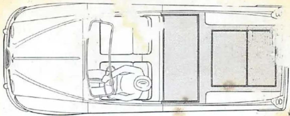
Loading capacity and passenger seats
natural_image
Top-down line drawing of a car interior layout showing driver, dashboard, and window (no text or symbols)a) Maximum loading floor
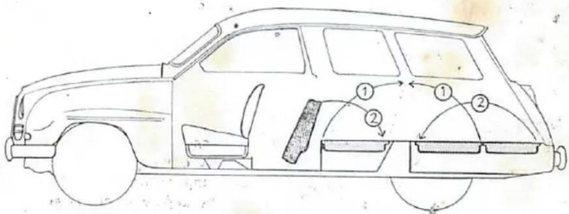
text_image
Technical diagram of a car with numbered parts indicating structural components or parts in the body.inversion into passenger seats
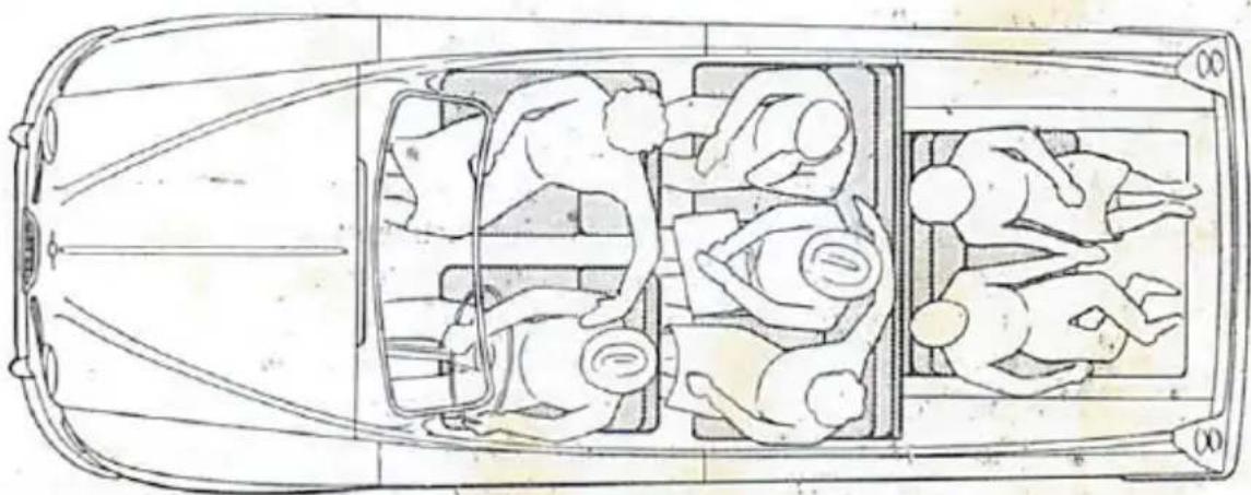
natural_image
Top-down line drawing of a car interior with multiple figures in various poses (no text or symbols)c). Seven passenger seats
Fig. 15. Loading capacity and passenger seats.
95B
Operation and Maintenance
Driving Instructions
Qualities of the car
General
Each type of car has its own characteristics and even cars of the same type and make may differ considerably depending on the condition of the car. Wheel alignment, steering mechanism, brakes, tires, shock absorbers etc. should therefore be kept well adjusted and in good condition for maintaining the features designed into the car. There are, however, other important things consider which affect the performance, e.g. how the car is loaded, road condition and driver. The following statements are thus composed exclusively with respect to the construction of the car.
Steering Qualities
The Saab 95 is understeered which means that, when cornering with a certain steering deflection, the car straightens out the turning circle as the speed increases. This feature tends to eliminate tail skidding and provides directional stability. If, however, owing to a brusque manoeuvre, tail skidding should occur, it is easily checked. When the car is loaded, however, the understeering is reduced and when a heavy load is placed in the rear, even oversteering tendencies may occur. To eliminate this tendency a heavy load should be stowed as much forward on the floor as possible. Due to the front wheel drive the car will maintain its directional stability on slippery roads even if the pedals are used carelessly.
Free Wheel
The free wheel device between clutch and main shaft can be engaged or disengaged by means of a control, located above the brake pedal. When the control is pulled out, the free wheel is disengaged, i.e. locked. The car should preferably be stopped before pulling out the free wheel control entirely. To engage the free wheel device, push in the control.
Generally the free wheel should be engaged, thus enabling the car to coast with idling engine, when the accelerator is released. This gives more miles per gallon of fuel and reduces engine wear. Gear-shifting is also carried out more smoothly and the driving becomes more comfortable. Take advantage of the free wheel, not only downhill, but also on level roads. The only occasions when the free wheel should be locked are when the motion of the car is required for starting the engine, and when descending long, steep grades in order to use the engine for braking the car, which reduces the brake lining wear. Further information is found under "Brakes" on the following page.

text_image
4-speed R 1 2 N 3 4
flowchart
graph TD
    R["Node R"] --> N["Node N"]
    N --> 1["Node 1"]
    N --> 2["Node 2"]
    N --> 3["Node 3"]
    style R fill:#f9f,stroke:#333
    style N fill:#ccf,stroke:#333
    style 1 fill:#cfc,stroke:#333
    style 2 fill:#fcc,stroke:#333
    style 3 fill:#cff,stroke:#333
Fig. 15. Gear shift positions
Gearshifting
The three speed gearbox is provided with synchro-mesh for 2nd and 3rd speeds, and in the four speed gearbox all forward speeds are synchronized, which means that the spur pinions of the gears cannot engage with their shafts before the rotation speed of the gear is the same as that of the shaft.
The synchronizer and the toothed couplings facilitate gear shifting
and for shifting to a lower gear, the clutch pedal need not be used provided that the free wheel is engaged. All gearshifts, however, should be carried out with easy and firm movements and with a slight, scarcely noticeable stop in the neutral position. Note that when shifting to reverse in a four speed gearbox, the shift lever must be pulled away from the steering column in the position , see fig 15, and at the same time it should be lifted up and pulled backwards.
When shifting, the clutch pedal should be released smoothly and carefully. Make it a habit always to remove your foot from the clutch pedal when not in use. To drive with a slipping clutch or with your foot resting on the pedal is bad practice since this will soon wear down release bearing and clutch linings. At standstill, the gear shift lever should be put in neutral and the clutch pedal released.
Brakes
The car is delivered with a thoroughly tested type of brake linings with very good heat resistant qualities, which will stand high temperatures without their proper function being impaired. Be certain, therefore, that original Saab linings, or linings recommended by SAAB, are fitted when relining the brakes.
There is, however, a limit to the temperature resistance for every type of brake lining. When driving downhill on mountain roads, with considerable altitude differences, the free wheel should be locked in order to use the engine for braking. In top gear the retarding effect is rather small and the second gear should therefore be engaged, or on extremely steep grades, the first gear. The speed must under these circumstances not exceed 60 km/h (40 mph) in second gear and 30 km/h (20 mph) in first gear.
Cold Start Device
For easy starting at low temperatures, the carburetor is provided with a cold start device, the control of which is placed to the left on the instrument panel. By pulling out the control knob, a special jet combination in the carburetor provides a richer fuel-air mixture than normally.
The cold start control has two positions. When starting a cold engine, the knob should be pulled out to the intermediate position, or under very cold conditions, to the outer position. While warming up the engine, the knob may be left in the intermediate position, but it should be pushed in completely as soon as possible. The engine should be warmed up by driving, not by idling at the curb.
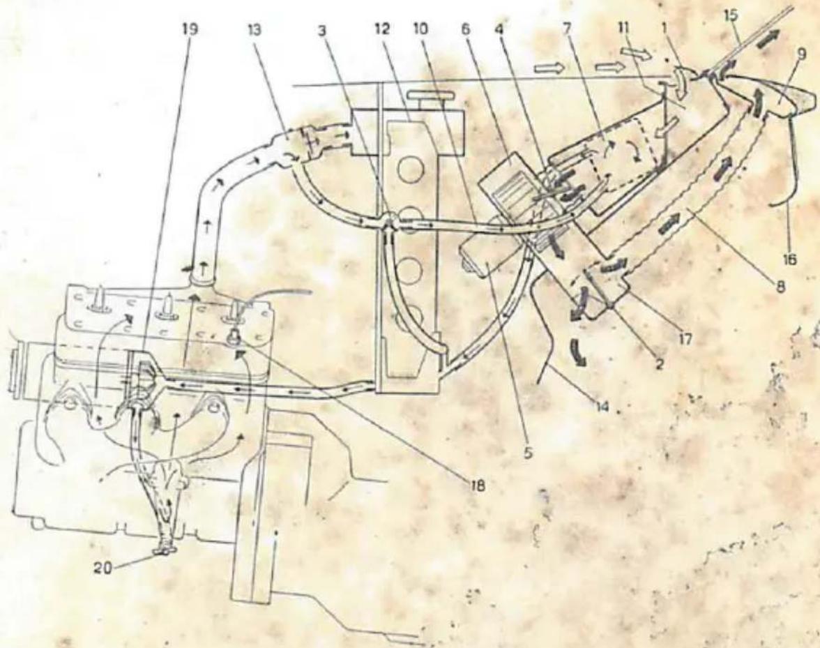
Preheater
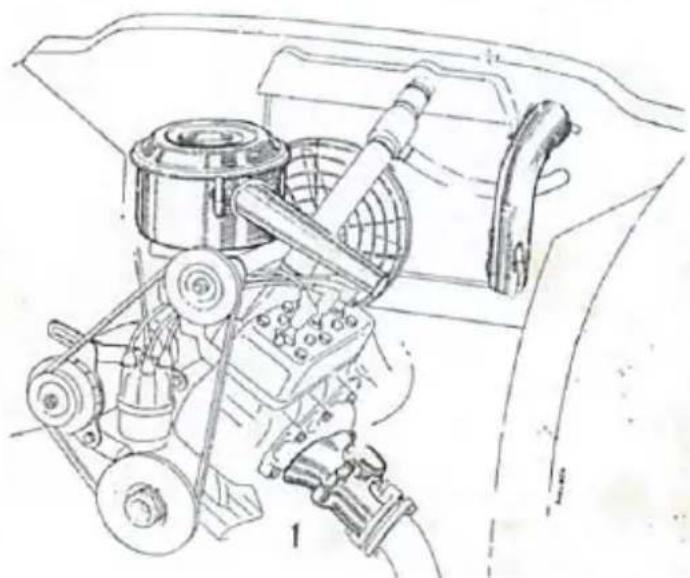
The engine is provided with a device for heating the carburetor air to prevent icing in the carburetor, which may occur at temperatures between -50^ and 15^ (20—60°F) if the relative humidity of the air is over 55% . The icing causes excessive fuel consumption and decreased engine power. It is therefore recommended that the preheater always be connected except during the warm season. When the preheater is not being used, the connection pipe should be secured to the bracket on the radiator frame, and the lower clamps fastened to the end of the pipe as shown in fig. 16.
natural_image
Technical line drawing of a mechanical assembly with gears and levers (no text or symbols)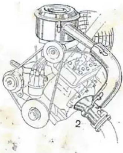
natural_image
Technical line drawing of a mechanical assembly with gears and housing (no text or symbols)Fig. 16. Preheater
-
Cold (summer driving)
-
Warm (winter driving)
Starting the Engine
Cold Engine
- Gear lever in neutral.
- Switch on ignition.
- Depress clutch pedal.
- Cold start knob out. — At very low temperature, keep the control pulled out entirely.
- Starter control out.
- Starter control in and cold start knob to intermediate position when engine starts.
- Release clutch pedal.
- Push in the cold start knob completely as soon as the engine becomes warm enough to operate on normal mixture.
NOTE
When the cold start is operated, never depress the accelerator as this will obstruct the function of the cold start device.
Push in the cold start control entirely as soon as possible.
Cold Engine at very Low Temperature
When stopping the engine and leaving the car outdoors in cold weather, proceed as follows to facilitate the subsequent cold start:
- Depress accelerator slightly.
- Pull out cold start knob.
- Turn off ignition and release accelerator.
For subsequent starting, follow starting instructions for "Cold Engine".
Warm Engine
- Gear lever in neutral.
- Ignition on.
- Starter control cut.
- Starter control in when engine starts.
If the engine fails to start, it may have received too much fuel. In this case, keep the accelerator depressed 5—10 mm ( 14 — 12 in.), while the starter is running.
Never use the cold start device when the engine is warm.
A few operation hints
General
The Saab 95 has an excellent roadability. However, even a skilful driver needs a certain time to get acquainted with a new car and its characteristics. It is therefore recommended to exercise care in the beginning to become gradually familiar with the car. Also the car needs a running-in period of approx. 3,000 km (2,000 miles) during which rough driving should be avoided.
Running-in
Every new car requires a certain running-in period during which it should be driven with care. Pistons, cylinder bores and bearings need to be operation for some time to produce smooth and resistive surfaces. Straining a new engine impedes this gradual bedding down and will probably shorten the life of the engine.

During the running-in period which covers the first 3,000 km (2,000 miles), avoid driving at too high engine speeds. This, however, does not mean that the engine, e.g. when driving uphill, should pull hard before shifting down. Select the gear to keep the engine speed sufficiently high at low road speed so that the engine is running without strain.
The following running-in speeds may serve as a general guide.
Avoid giving full throttle during the first 3,000 km (2,000 miles) and remember that the fuel should contain 4 % of oil during this running-in period.
Driving Economy
To achieve the best economy with regard to fuel consumption as well as wear, the Saab 95, as every other car, needs careful and even driving. Avoid excessive acceleration and high engine speeds especially in low gears. As previously described, the car has a free wheel device which enables further reduction of the fuel consumption. The car is also equipped with a device for heating the carburetor air, see fig. 16, thus preventing icing in the carburetor which may occur under cold and damp weather conditions and is noticeable only by increased fuel consumption and poor idling.
Driving on Slippery Roads
When driving on slippery roads it is more important than ever that the characteristics of the car be maintained. Especially tires and brakes must be in proper condition to ensure even braking power. A driver who prefers to make use of the engine braking power can lock the free wheel. There is no general recommendation for driving with locked free wheel and each driver may choose the alternative which suits him best.
Regardless of whether the free wheel is locked or not when you are driving on slippery roads, the most important thing is to be able to use the wheel brakes. Even under the most slippery road conditions, engine braking cannot stop the car in shorter distance than proper braking with the wheel brakes, provided that the car is two-wheel driven and has four-wheel brakes.
In case of a tail skid, the general rule is to give gas and to steer in the same direction as the tail skids. If the front wheels skid, let up on the accelerator to regain steering and traction ability and then gradually open the throttle again.
All pedal operations should be carried out more smoothly and carefully when driving on slippery roads. As soon as the winter season begins, take the opportunity to practice turning and braking in some open area which is free from traffic. In a situation when a skid occurs, this practice may prove quite useful, since you will know instinctively how to regain control of the car.
Learn the technique of winter driving and it will become a pleasure.
Maintenance
Useful hints
- Be sure that the ignition is switched off when the engine is not running, otherwise the crankcase may be flooded with fuel if the carburetor needle valve should be leaking. It is also possible that ignition coil and breaker points may be damaged.
- Learn the quickest way to start the engine. If the engine is cranked too long without starting, it will become flooded and more difficult to start.
- Drive in top gear whenever possible without straining the engine at low engine speeds. Avoid fast driving in 1st and 2nd gear.
- Make use of the free wheel as much as possible. Release the accelerator entirely when the car is maintaining speed without throttle. When driving on motor roads and similar highways allowing high speeds, the accelerator should be released entirely now and then in order to make use of the free wheel, and to allow the car to coast for a while with idling engine. This driving technique affects the average speed very little but is beneficial to the engine and gives more miles per gallon.
- Do not change carburetor jets. Adjustments, if required, should be carried out by qualified Saab mechanics.
- Keep the brakes adjusted so that they do not drag.
- Keep the battery well charged. A poorly charged battery cannot start the engine quickly. It may also freeze at low temperatures.
- During the cold season the door locks should be prepared in order to prevent ice formation in the lock cylinders. There are several means available at the service shops for this purpose. Should,
however, the lock cylinder have stuck, be careful not to destroy the key. Try to warm up the lock in some way until the ice melts and the key can be turned. To prevent new ice formation the lock cylinder may be greased sparingly with ethylene glycol or Silicone spray.
NOTE. Be careful to protect the finish from glycol.
- When refueling at temperatures below 0°C (32°F), the oil should be diluted with an equal amount of gasoline before being poured into the tank.
The special Saab-oil does not need pre-mixing.
-
Do not change to using cold spark plugs as long as the hot ones function satisfactorily. Consult your approved service shop before any change.
-
When loading the car, a heavy load should be stowed as much forward as possible to avoid oversteering tendencies.
Engine
The most favorable operating temperature of the engine is approx. 90°C (195°F) i.e. rather high on the thermometer scale range. Keep the coolant temperature too high rather than too low. Do not forget to close the wheel housing openings behind the radiator when the cold season begins.
The engine should always be kept in a good operating condition. For normal driving it would be decarbonized after every 30,000 km (20,000 miles). Carbon deposits in combustion chambers, lucts and exhaust system increase the exhaust resistance and impair the efficiency and economy of the engine. Carbonization can be reduced by avoiding slow driving in top gear and by using oil and gasoline of good quality.
Decarbonizing and other major maintenance operations should be carried out by an approved Saab service shop.
Fuel System
Air Filter
The air filter in the suction silencer should be replaced every 30,000 km (20,000 miles) or at least every second year.
The filter element should be protected against moisture, and must therefore not be washed or oiled. It may be necessary, however, to clean the interior of the filter housing (the suction fencer), especially when changing the filter element. This should be dried out carefully in order to prevent impurities from falling down to the ca. uretor.
Carburetor
It is essential that the carburetor be kept free from impurities. For this reason a filter, 10, is provided in the carburetor feed pi connection. This filter should be inspected regularly and cleaned whenever necessary as should also the jets. The design of the Solex carburetor allows the removal of all jets, except the idling air jet, without dismantling. Positions and designations of the jets are shown in figs. 6 and 17. It is important that carburetor adjustments are carried out in accordance with the manufacturer's recommendations, otherwise the proper function of the carburetor and thereby the engine operation may be impaired. Wrong carburetor adjustment may cause abnormal fuel consumption and rapid wear of the engine.

text_image
Technical diagram of a mechanical device with numbered components for identificationFig. 17. Carburetor, Solex 40 AI
- Starting air jet
- Idling mixture, adjustment
- Starting jet
screw (see fig. 6.) - Emulsion jet
- Idling speed, adjustment screw
- Idling jet
- Cold start lever
- Main jet
- Fuel feed pipe connection with
- Idling air jet
filter
Idling djustment
Idling djustment should always be carried out when the engine is warm 'he proce' is as follows and the numbers refer to fig. 17.
- the idli need rather high with the adjusting screw 8.
-
Adjust the engine to run uniformly with the adjusting screw 7, which is achieved when the screw is opened about 2 turns.
-
Adjust the engine speed with the screw 8 until the proper idling speed, 700—800 rpm, is attained.
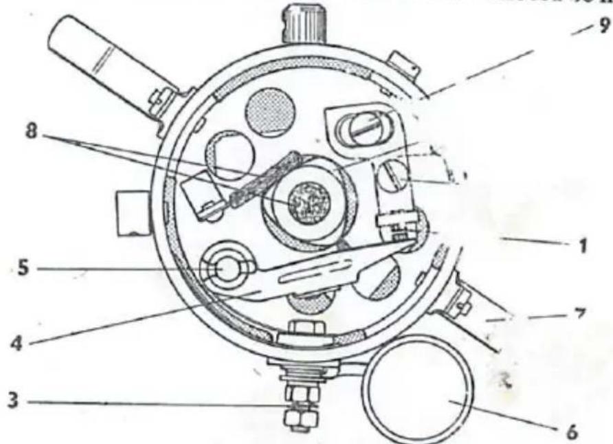
Fuel Pump
In the fuel pump there is a filter 16, which can be removed by screwing out the plug 17. This filter should be cleaned every 12,000 km (8,000 miles) or whenever impurities in the fuel are suspected. If the fiber washer 15, fitted between the plug and the pump housing, comes loose, be sure to replace it when inserting the plug. The contact points in the breaker mechanism should also be checked and if necessary adjusted every 12,000 km (8,000 miles). In case the owner himself wants to carry out this operation, the procedure is as follows:
- Check that the ignition is switched off so that the cable to the fuel pump is dead.
- Remove the terminal nut 21, which holds the electric cable.
- Remove the cable and the nut 22 after which the cover 9 can be removed.
When carrying out the following operations, the greatest cleanliness should be observed to prevent grease or impurities from entering the breaker mechanism.
- The contacts 6 and 7 can now be cleaned by pulling a strip of stiff paper or very fine emery cloth between their faces. Should

text_image
Technical diagram of a mechanical assembly with numbered parts and labeled partsFig. 18. Fuel Pump The numbers refer to the tex

text_image
SAABthe points be burnt, or otherwise be in poor condition, the pump should be checked by a service garage.
- Assemble cover 9, nut 22 cable, and nut 21 to their original positions. Tighten the terminal nut 21 firmly to ensure satisfactory contact.
. Cooling System
General
When topping up or draining the cooling system, the heater control 4, fig. 33. should be in the "Hot" position. Note that the filler cap must be loosened when draining. Topping up of the radiator must be done in two steps, so that the heater element will also be filled with coolant. When the radiator is full, more coolant may be added, if the engine is raced moderately for a few seconds. Use only clean coolants, preferably pure rain water, which eliminates the formation of deposits in the system. Never top up with a considerable amount of cold water if the engine is hot, as this may crack the cylinder block.
Greatest care should be exercised when removing the filler cap in case the coolant is boiling. Unscrew the cap carefully to let out the steam before removing the cap.
Cleaning the Cooling System
The coolant should be changed twice a year, spring and autumn, and in connection with this the system should be cleaned by flushing. The flushing is carried out in opposite direction to the normal flow of the coolant. Thus the block should be flushed through the upper neck and downward and the radiator through the lower pipe and upward. Cracked hoses and defective clamps should be replaced.
If the flushing proves to be insufficient for removing deposits, the system should be cleaned by a service shop with special equipment for cleaning cooling systems. In order to prevent further formation of deposits some rust inhibitor or glycol may be used.
Remember
-
That the heat control should be in the "Hot" position when draining and filling the cooling system.
-
That filling of coolant should be carried out in two steps, so that the heater element becomes completely filled up.
-
That the filler cap should be loosened when draining.
Radiator Repairs
A leaky radiator core should be repaired by soldering. Patent solutions added to the coolant in order to seal the radiator should be used only in case of emergency as they may clog the cooling jackets and pipes.
Anti-freeze Solutions
During the cold season when the temperature often falls below the freezing point it is necessary to fill the cooling system with a freeze-proof mixture instead of water, which may freeze and damage the radiator core or the cylinder block. Methylated spirit or ethylene glycol may be used as antifreeze solutions. Methylated spirit, how- is not very suitable because of its low boiling point, especially driving with high coolant temperature, which is desirable during the cold season to make effective use of the heater. See page 58.
Glycol, on the other hand, has a boiling point above that of water and therefore only water need be added when replenishing. The dis-
| ethylene glycol volume % | Freezing point | Boiling point | Spec. grav. | ||
| °C | °F | °C | °F | ||
| 10 | -4 | 25 | 101 | 214 | 1.012 |
| 20 | -10 | 14 | 102 | 216 | 1.027 |
| 30 | -17 | 2 | 103 | 217 | 1.041 |
| 40 | -26 | -15 | 104 | 219 | 1.055 |
| 50 | -39 | -38 | 106 | 223 | 1.068 |
| 60 | -56 | -68 | 109 | 228 | 1.076 |
| Ethylene glycol (U.S. gal.) | Volume % | Freezing point | Boiling point | Spec. grav. | ||
| °C | °F | °C | °F | |||
| 1 quart | 13 | —6 | 21 | 101 | 214 | 1.012 |
| 2 quarts | 25 | —14 | 7 | 103 | 217 | 1.041 |
| 3 quarts | 38 | —24 | —11 | 104 | 219 | 1.055 |
| 4 quarts | 50 | —39 | —38 | 106 | 223 | 1.068 |
advantage with glycol is that it is rather expensive, and like methylated spirit, it must be handled with care as it can spoil the finish of the car. It also reduces the thermal conductivity of the water and thus it should not constitute too great a percentage of the coolant.
Transmission
Check the oil level in the transmission every 3,000 km (2,000 miles) by unscrewing the level opening plug 2, fig. 7. The oil level should not be more than 5 mm (1/4 in.) under the opening. Add oil when required and be sure not to mix different lubricants.
The transmission oil should be changed the first time after the running-in, i.e. 2,500—3,000 km (1,500—2,000 miles) after which oil is to be changed every 12,000 km (8,000 miles) or every autumn. Drain the transmission after the car has been driven 20 minutes and rinse with flushing oil. The transmission should then be filled with approx. 2 liters (2 U.S. qts.) of oil until it comes out through the level opening. See Lubrication Chart.
text_image
Technical diagram of a mechanical linkage system with labeled parts 1, 2, and 3Fig. 19. Clutch Cable with Adjusting Nut
- Adjusting nut
- Bracket at firewall
- Pulley segment
Clutch
The clutch pedal should have a play of about 25 mm (1 in.) which is adjusted with the nut 1, fig. 19. Screw out the nut to reduce the play. To avoid excessive wear of the clutch linings and the release bearing, the play should be checked regularly.
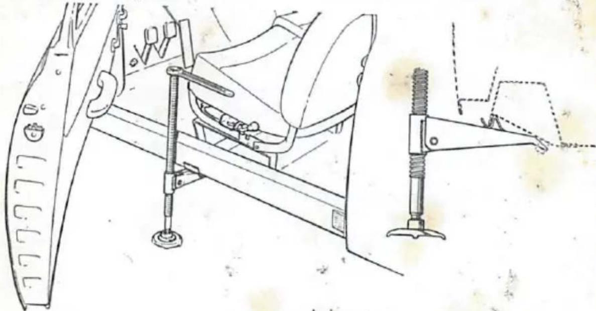
Jack and Spare Wheel
When jacking up the car for wheel change, brake adjustment etc. the jack should be fitted in the bracket located under the floor member, see fig. 20.
natural_image
Technical line drawing of a vehicle suspension system with attached bracket and guide rail (no text or symbols)Fig. 20. Positioning of the Jack
When using a garage jack make certain that it does not damage the underside of the body. Strongpoints for the jack are provided. The front strongpoint is a bent plate behind the muffler and the rear one is located on the body center line, just in front of the rear axle tunnel. Place a piece of wood on the lifting head when lifting the rear end of the car.
The spare wheel, the jack and the tool kit are placed under the rear seat cushion in the car, easily accessible even when the car is loaded.
Suspension
Front and rear axle suspensions require no particular service since rubber attachments are employed throughout. If suspension troubles are suspected, the car should be checked by an authorized service shop.
Brake System
Replenishing Brake Fluid
Inspect the brake fluid level every 3,000 km (2,000 miles) and check that the holes in the lid are not clogged. Never use inferior brake fluids, which may ruin the rubber parts and thus impair the functioning of the hydraulic system.
\* Bleeding of Brake System
A resilient brake pedal or braking power that is obtained after two or more pedal depressions signifies air in the hydraulic system which should then be bled as follows:
- Check that the container is well filled and make sure that the vent holes in the cover are not clogged.
- Connect a suitable hose to the bleeder screw 1, fig. 21, inside the left rear wheel.
- Immerse the free hose end in a glass jar filled with clean brake fluid.
- Open the bleeder screw 12 —1 turn.
- Have the pedal pumped with long even strokes until the discharged fluid is free from air bubbles. The end of the hose should be kept immersed during the bleeding.
- Tighten the bleeder screw during a pedal depression.
- Bleed also at the front wheels in the sequence right and left. Check that the fluid level in the container does not get too low.
- Check that all bleeder screws are tightened, and top up with brake fluid. Never use the fluid collected in the jar.
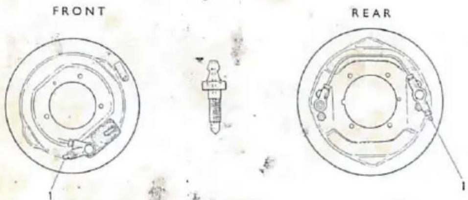
text_image
FRONT REAR 1 1Fig. 21. Location and Design of Bleeder Screws
\* Brake Adjustments
If the stroke of the brake pedal has increased gradually during an extended period of driving, it is likely that the brake linings are worn. Never let the fully pressed down pedal come closer to the floor than two inches.
The brakes are adjusted in the following manner:
and
^7je
two wheels are free from the ground.
the opening for adjustment, remove one wheel until the hole faces one of the each front wheel, one at each rear
ing screw with a screwdriver until the wheel is inscrew one or more notches until the wheel
- Wh our wheels have been adjusted, check that the brake pedal is 5—10 mm ( 14 — 12 in.) otherwise the brakes will drag when the pedal is released.
If a wheel cannot be locked with the adjusting screw, the brake linings are badly worn and should be replaced without delay. To ensure uniform brake power, reline both front wheels or both rear wheels and never on one side only. When relining, use only Saab original linings, or linings recommended by SAAB.

text_image
FRONT 1 1 REARFig. 22. Foot Brake Adjusting Screws
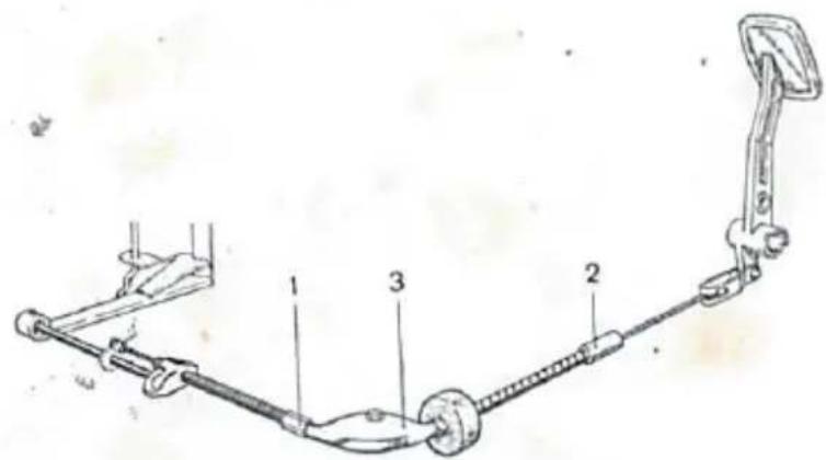
Parking Brake
The brake lever movement is transmitted Bowden cables. The brake lever play is 23, accessible from the driver's seat. The brake lever two notches before t'les must not be carried out unless the to make ted as previously described.
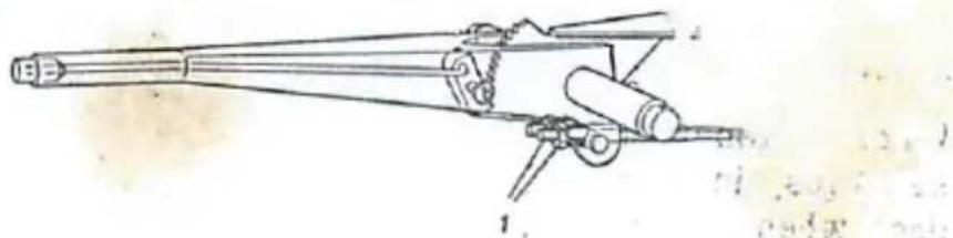
natural_image
Line drawing of a mechanical gun with lever and barrel (no text or symbols)Fig. 23. Brake Lever with Adjusting Nuts
Wheels and Tires
In case of puncture the air leaks out very slowly from a tubeless tire since the hole in the synthetic rubber layer is squeezed almost tight by the tire pressure. If the penetrating object remains in the tire, pressure may be retained long enough for braking safely, or even proceeding to a service station, before the tire is deflated. Furthermore, the repair of a tubeless tire is so simple that in most cases removal of the wheel is not required.
Fitting and repair of tubeless tires should preferably be carried out by a tire repair shop. The following directions are intended for those who wish to carry out minor repairs themselves or for those occasions when no service is available.
Fitting Tires
When fitting a tire to the rim, be sure that the surfaces of the tire beads are clean and even. The tire bead and the inside of the rim edge should be thoroughly cleaned and any rust should be removed with a wire brush and steel wool. Particular attention should be paid to the area around the valve hole. If the corrosion is so severe that the surface has become rough, the affected are the tire bead should be coated with a thick layer of rubber. The tire should then be fitted before the cement has dried seams on the rim should be filed off if there is reason to leave that they may cause air leakage.
After the valve has been attached to the wheel rim, the tire is fitted. This operation should be carried out very carefully to ensure
tire bead damaged by sharp edges on the tools. Check to be properly seated in the rim. A most simple to place the wheel at a 45° angle against a wall im with your foot. Turn the wheel and repeat the the other side.
The initial inflation should be done with the valve needle removed, so that the tire is properly seated on the rim by the suddenly increased air pressure. Insert the needle, inflate to 2.5—3 kp/cm² (35—40 lbs./sq.in.) and then bleed the tire until the proper pressure is obtained.
Repair of Leaks
If a tire does not keep its pressure, it is possible to locate the fault by merely inspecting the tire and after the puncturing object, if any, has been removed, the tire can often be repaired without removing the wheel. To locate minor leaks it may be necessary to remove the wheel and immerse it in water.
Tires
A puncture can be repaired without difficulty by inserting a rubber plug in the hole after the plug and the hole have been coated with rubber cement. A special needle is required for this operation. Repair kits containing a needle, plugs of various sizes, and rubber cement, i.e. everything required for repairing tire punctures, are available in the market. Directions for use are also enclosed.
Wheel Rim
Air leaks due to minor deformation of the rim may be remedied by straightening the edge using hammer and anvil. Small holes etc. are repaired by hot riveting and if an existing rivet is leaking, its head may be hammered out. A rim leak must never be sealed by brazing or welding. For safety reasons a cracked rim should be replaced instead of being repaired.
Valve
Air leaks around the valve can often be stopped by cleaning the rubber washers and valve and then coating with rubber cement. If the valve has a hexagon nut, this can be tightened. If the valve is integral or if the remedies mentioned above fail to stop the leak, the valve must be replaced. Before fitting a new valve, inspect and clean its contact surface on the rim.
Tire Pressure
Check the tire pressure once a week with a re and follow carefully the directions on page 9.
A tire with correct pressure makes road contact tread. Uniform wear and effective traction is thus act.
Tires with too high pressure cause a bumpy ride and wear excessively in the middle of the tread, where cracks may occur in the bottom of the pattern grooves.
Tires with too low pressure are worn most on the outer edge of the tread. They impair the roadholding by causing the car to sway when cornering, and cracks may occur on the tire sides.

text_image
Technical diagram of a circular mechanical component with numbered parts and directional arrows indicating motion or flow.Fig. 24. Tightening Wheel Bolts
Interchanging Wheels and Tires
The front tires are subjected to heavier wear than the rear ones, and after a certain period of driving it is therefore advisable to shift the wheels, so that the least worn tires are placed in front. Note that some tires may have a certain rotation direction, which must be maintained. By shifting the wheels the life will be approximately the same for all the tires.
Fig. 24 shows the tightening sequence of the wheel bolts.
Front Wheel Alignment
It is essential that the alignment of the front wheels be correct. Wrong alignment impairs the road characteristics and it may be tiring and difficult for the driver to manoeuvre the car. The abnormal wear on tires and steering mechanism will result in increased tire and repair expenses.
To prevent incorrect front wheel alignment, the car should be taken
to an authorized service garage for inspection and possible adjustment every 6,000 km (4,000 miles) or whenever there is reason to believe that the alignment is faulty.
The various alignment angles are shown in the figure below. Note, that the dimensions A and B are measured between the wheel rims.

text_image
Technical diagram showing mechanical assembly with labeled components and dimensional annotationsFig. 25. Front Wheel Alignment
-
Toe-in B-A = 2 mm + 1 (08 in + 04)
-
Camber = 3/4°
-
"King pin" inclination* = 7°
-
Caster 12
Electrical System
Battery
The battery is one of the most important parts of the car and should be checked and serviced carefully.
Check the electrolyte level at least once a month in the winter and every second week in the summer. It should be 6—8 mm (approx. 1/4 in.) above the cell plates. Use only distilled water when topping up. The charge of the battery is measured with a hydrometer which shows the specific gravity of the electrolyte. The specific gravity values from fully charged to discharged are listed in the table below.
In order to prevent corrosion of the terminals, they should be coated liberally with Vaseline. All grease, dirt, etc. should be removed before coating. Check also that the battery is firmly secured and that the terminal nuts and the ground connections are tightened.
| Battery condition | Specific gravity |
| Fully charged | 1.28 |
| 34 charged | 1.24 |
| 12 charged | 1.21 |
| 14 charged | 1.16 |
| Discharged | 1.12 |
* Since this car has ball joint suspension of the wheels, the term king pin refers to an imaginary line through the centers of the ball joints. See fig. 25.
Avoid long and heavy discharges of the battery because they shorten its life considerably. In case of repeated attempts to start the engine, the battery should be allowed to recover for a short while between attempts.
Generator
The generator is located to the right of the engine and is driven by a V-belt from the crankshaft pulley. To tighten the belt, loosen the bolts 1 and 2, fig. 26, and pull the generator outwards. The correct tension is attained when the belt can be pressed inwards about 6—8 mm ( ^1/_4 in.) on the longest run. See fig. 26. Do not overtighten the belt, since this will cause excessive load on the generator bearings and heavy belt wear. When the tension has been correctly adjusted, tighten the bolts 1 and 2.
Should the generator or relay be defective, take the car to an approved service garage without delay. The generator should be lubricated when overhauled.

text_image
6-8 mm 1 2 3 Fig. 2 1 2. 3.Fig. 26. Adjustment of Belt Tension
- Adjusting bolt
- Fastening bolts
- Index for ignition timing (piston in cyl. 2 at T.D.C.)
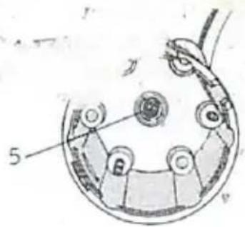
Ignition Distributor
The ignition distributor is mounted to the right on the engine. The rotor is driven by the crankshaft via a worm gear and a pinion. It rotates clockwise and as shown in fig. 28, the firing sequence is 1—2—3 (No. 1 cyl. being the rear one).
It is essential that the distributor gear be lubricated regularly every 3,000 km (2,000 miles) and that the contact gap be checked every 12,000 km (8,000 miles). The distributor shaft and the lubricating felts should also be oiled at this time. See Lubrication Chart.
\* t out-ct Point:
The (8,000 miles, that the contact and point 5.1 we the distribution of
extent that they 1
Do not forget to lubricate the brea' ant as used on the lubricating sites for the can and rotor shaft. Note. All lubrication in the distributor should be moderate.
text_image
Technical diagram of a mechanical device with numbered parts labeled 1 through 9Fig. 27. Ignition Distributor
- Contact points 7. Clamp spring
- Breaker cam
- Primary cable terminal 8. Grease felts
- Adjusting screw
- Breaker arm 10. Fines
- Breaker arm pivot 10. Fixed breaker po
- Condenser
After checking the contact points, the point adjusted. The correct gap is 0.3—0.4 mm (0.12—0.5) when the breaker arm peg is on the highest point feeler gauge when checking. The gap is adjusting lock screw 11, fig. 27, of the stationary point. The adjusting screw is obtained lock screw. Chec
Note. When fitt ie re one lock , sh must be replaced by a new one. After adjustment of the point gap, always check the ignition timing.
ter 1t
-m, of
one cylinder, engine and tributor are indexed with cylinder 2 as determinant for the timing, which is used out as follows:
wictor cap re- breaker turn the til the index aft., pulley coincides with the crankcase index underneath the distrib- butor, as shown in fig. 26. pistor in cylinder 2 is top dead centre.
index of the rotor would now coincide with the index of the distributor body. This index is located e rear side of the body and to the left of the guide g which also serves as a support for one of the clamp springs. See fig. 28.
- Switch on ignition and by using a test lamp for indication, turn the crankshaft until the breaker points close. We re that the advance regulator weights are retracted by turning the rotor anticlockwise. When the setting is correct the
text_image
5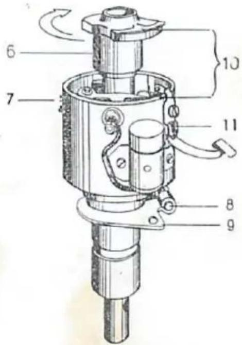
text_image
Technical diagram of a mechanical device with numbered components and directional arrows indicating motion or flow.Fig. 28. Ignition Distributor
- Ignition cable, cylinder 1
- Ignition cable, cylinder 2
- Ignition cable, cylinder 3
- Cable to ignition ce.l
- Center carbon te pinal
- Rotor
- Ve-He
- Dip again and screw
- Loc. rotor, f
- Indexes for ignition timing
- Clamp spring support with guide lug.
points begin to t Poi.t 10°, or if a dial gauge is use (.028 in.) before I.D.C. If a dial gauge is not available, the distance between the pulley index and the crankcase index, fig. 26, may be measured. The distance measured on the pulley periphery corresponding to 10° is 12—13 mm (½ in.).
If adjustment of the timing is required, proceeds follows:
a. Turn the crankshaft until the piston before T.D.C. (See item 3 above). Note the rotor and distributor body should
b. Loosen screw 8, fig. 28, and turn the until the weaker points open. Make certain that the advance regulator lights are retracted. When the correct setting is obtained, tighten the distributor screw.
d. Check the correctness of the timing by turning the crankshaft a few full turns.
- Cle: the distributor cap, inside as well as outside, with a dry and clean cloth, and check that all contact faces are clean and undamaged. Also check that the center carbon terminal 5 slides freely in its holder. Clamp on distributor cap so that the lug on the spring attachment fits in the corresponding notch. Check that the ignition cables are correctly inserted and make good contact. If required, the distributor shaft should be lubricated through the nipple at the front of the distributor body and at the felt in the shaft under the rotor, which must be removed.
Important
All high tension insulators must be kept clean and dry. The following parts should be cleaned every 6,000 km (4,000 miles): ignition coil bakelite cap, distributor cap (inside and outside), ignition cables and spark plug insulators.
Spark Plugs
The spark plugs should be cleaned after approx. 6,000 km (4,000 miles) driving. At the same time, check with a feeler gauge that the spark gap is 0.7 mm (.028 in.) If adjustment is required it must be done with the side electrode since the insulator may crack if the
centro. e. trade is subjected to bending. After 10,000—15,000 km (6,000—10,000 miles) the spark plugs should be replaced.
The type of spark plugs to be used is determined to a great extent by how the car is being driven. Hot spark plugs should be used for running in, city driving and when the car is used ordinarily. Long distance, high driving requires cold spark plugs in exceptional
only if the hot ones have proved to burn down... ... 11, Champion UK 10 or equivalent are generally the plugs for ordinary use of the car.
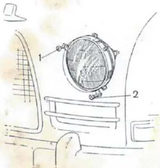
\* Aiming Headlights
The headlights are mounted in the hood by three attachm of which is pivoted and the other two serving as adjusti See fig. 29.
The upper screw, 1, is used for horizontal adjustment and by screwing the lower one, 2, in or out, the beam is raised or lowered respectively.
Before aiming, check that tire pressures are correct and place the car on a level floor and square with the target. The car should be unloaded except for the driver.
Fig. 29. Screws for adjusting Headlights
- Horizontal adjustment
- Vertical adjustment
text_image
Technical diagram of a car interior with labeled components, showing a circular component mounted on the side panel.It is very important that the headlights be correctly adjusted in order to ensure the best possible illumination of the road and at the same time to avoid dazzling on-coming traffic.
Sealed Beam Head
A = 50 mm (2 in.)
B = 150 mm (6 in.)
C = 480 mm (19 in.)
text_image
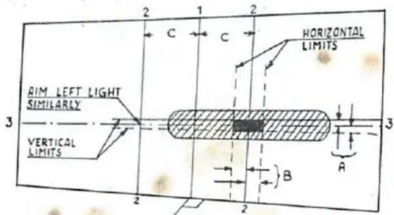
AIM LEFT LIGHT SIMILARLY VERTICAL LIMITS 2 1 2 C C HORIZONTAL LIMITS 3 A B 2 2
natural_image
Line drawing of a vintage car viewed from the side, showing front and rear panels (no text or symbols)Fig. 30. Aiming Sealed Beam Headlights against Target
- Car center line
- Vertical and
- Horizontal center line of headlights
the aiming of Sealed Beam asymmetric headlights should be cried out against a target, as shown in fig. 30, or with special equipment giving equivalent results. The various lines of the target re the car center line, 1, the two vertical headlight center lines 2-2 and the horizontal headlight center line, 3-3.
Measure the distance between headlight and target, 7.5 meter (25 ft.) and adjust the line 3-3 to be horizontal at the height of the headlight centers. Switch on the main beams and aim one at a time, with the other one masked. The centers of the high intensity zones should be adjusted against the intersection points of the lines 2-2 and the line 3-3. However, there are certain limits within which the beam centers should be kept. Thus they must not be to the left of or more than 150 mm (6 in.) to the right of straight ahead, neither above or
more than 100 mm (4 in.) lower than the This horizontally and vertically limited area is shown as a black field on the target in fig. 30. If the headlights are aimed according to this description, no separate adjustment will be required for the low beams.
Asymmetric Headlights (R.H.D.)

text_image
380mm 380mm 60mm H Fig. 31. Aiming R.H.D. Asymmetric Headlights against Target H=Height of headlight centersH=Height of headlight centers
The target for aiming the asymmetric headlights is shown in fig. 31. Place the car at a distance of 5 meters (17 ft.) from the target, switch on the low beams and mask one lamp. Check, and if necessary, adjust the beam until the horizontal part of its light-darkness limit falls exactly 6 cm (23% in.) below and entirely to the left of the headlight center (+). The inclined part of the light-darkness limit must be entirely to the right of this mark and should thus intersect the horizontal limit under the headlight center.

natural_image
Sketch of a car with visible engine and roof (no text or symbols)e other headlight similarly, after which a routine high beams should show that these are symmetric.
then temporarily using the car for L.H.D. the asymmetric the lens should be covered with a piece of nontrans- king tape, by which ordinary symmetric light will be
Lulb 4. nacements
Headlights U. S. A., Sealed Beam
Open the hood and disconnect the cables from the unit. Screw out the headlight adjustment screws and detach the unit by loosening its upper pivoted attachment. Note the coil spring at each attachment. Separate the sealed beam unit from the sheet metal body by detach- g the chromium-plated clamp ring. Fit the new sealed beam unit in the headlight body and secure it by tightening the screws of the clamp ring. Make sure that the unit is correctly installed by following the maker's instructions. Install the headlight in the hood. First fit the upper attachment with spring to the hood and then screw in the two adjustment screws. Fit the two coil springs and tighten screws. Connect the cables to the unit and aim the headlights.
Domestic Headlights
Open the hood and remove the rubber cap behind the headlight. Disconnect the lampholder by detaching the spring clamp. After removing the bulb insert the holder and secure it with the spring
Use a clean cloth or the bulb wrapping when inserting the new bulb. Avoid touching it with your hand. Make sure that the guide lug is properly seated and fit the rubber cap so that it seals tightly around the holder.
Instrument Lights
All the bulbs in the instrument unit are fitted in removable sockets. They are very easily replaced and accessible from under the instrument panel.
Other Lamps
Loosen the attachment screws are placed the lamp and check that it is contact. Clean the lamp and the rest by tightening the screws and be sure the rubber packing.
to glass (and frame). Re- itioned and makes good at the glass (and frame) in proper sealing against
Fuses
The electrical system is equipped with twelve fuses, two intended for optional extras or as spares. The fuses are a fuse box under the hood on the right hand side of the box lid is indicated the electric units protected by each fi
If the fuse is intact when locating a fault, the cause may be or contact at some cable connection. Check that the connection are properly tightened and not oxidized. When fitting a new case, it sure that it makes proper contact.
Note. A fuse does not protect the part of a circuit before the fuse.
Should the same fuse blow frequently, the car should be taken to a service shop without delay for insulation tests of cables and equipment.
Body
Care of Finish
The car should be washed by hosing with clean water until most of the dirt is removed, the rest being wiped off with a sponge and plenty of water. Be careful not to scratch the finish. The car should then be hosed again and dried with a clean chamois. To get a satisfactory result, washing should preferably be done in the shade.
The wheel housings and the rear axle tunnel should also be hosed with water when the car is washed.
If the car is frequently left outdoors, especially in sunshine the finish may gradually lose its luster, but it may be restored v good quality car polish. The car should then be waxed.
Spots of asphalt, oil etc., should be removed without delay using a cloth moistened in gasoline, turpentine or similar solvent. Having removed the spot, rinse off the cleaner with water.
Should the finish be moderately damaged, for example by a flying stone, the spot can be cleaned and then coated with a suitable air-drying touch-up paint. Small cans containing paint for Saab cars are available as spare parts.
Care of Upholstery
The upholstery in the car is plastic-coated cloth and silk fabric. The plastic-coated cloth rep and is oil and gasoline proof. Should the plastic surface be so easily be cleaned with water and some synthetic detergent, orally soiled, by oil or grease, it can be cleaned with kerosene, 10 morethylene, etc. These organic solvents,
SADB 95B
95B
3 carburetor are

= engine and the .
O. plugs.
f. Check that the cold start lever on the carburetor operation correctly. Let the starter crank the engine while the accelerator is kept pressed down constantly 5—10 mm ( 14 — 12 in.). g. Check that the fuel pump is feeding fuel by loosening the fuel hose fitting at the carburetor and switching on the ignition for a moment.
- Should the engine still fail to start, check if sparks appear at the spark plugs:
a. Remove the ignition cable from one of the spark plugs and hold its terminal close to the cylinder block while the starter rotates with the ignition switched on. A spark should now jump the gap between cable and cylinder block. Repeat for the other spark plugs. b. If there is no spark or only a faint one, check that the ignition cables are properly inserted in the distributor cap and ignition coil. Remove the cables and clean their terminals. c. Remove the distributor cap and wipe it dry. Inspect and clean all connections.
- Sparks appear, but the engine fails to start although fuel is properly fed to the carburetor:
Check that the carburetor jets and ducts are not clogged. Clean the carburetor if required, see figs. 6 and 17.
If the engine misfires, the cause may be:
- An ignition cable has loosened or become grounded.
- A spark plug is fouled. Clean and adjust gap.
- An ignition cable makes poor contact in the distributor cap.
- The distributor cap is cracked or moist.
- A contact in the distributor cap is oxidized or burnt.
Reduced engine power. Check that:
- Ignition cables are properly connected.
- Spark plugs are clean and have correct gaps.
- There is no short in the ignition system.
-
Carburetor icing does not occur. If weather is cold and damp, connect the preheater.
-
Carburetor jets and ducts are not clogged.
-
Accelerator is not stuck thus obstructing the throttle valve motion.
No negative reading on the ammeter when ignition is switched on. May be due to:
-
Blown fuse for ignition coil and fuel pump.
-
Discharged battery or a loose battery cable.
-
Poor contact at the ignition switch or at the ammeter.
-
Faulty ammeter.
No sparks at the spark plugs, although ignitic is switched on and ammeter reading is correct. The cause may be:
- Poor connections between cables and distributor or ignition coil.
- Ignition cable is ruptured, causing short-circuit.
- Moisture in distributor or on spark plug insulators.
- Distributor rotor or cap is cracked.
- Defective ignition coil.
A cracked distributor cap or ignition coil cover may be temporarily repaired by cleaning it and scraping the crack clean.
Ammeter fails to register when driving, although the battery is not fully charged.
- V-belt broken or not sufficiently tightened.
- Generator relay defective.
- Generator carbon brushes badly worn, stuck in their holders, or the collector is burnt.
Starter runs very slowly:
- Battery discharged.
- Ground connections, cable connections of battery or starter are oxidized or not sufficiently tightened.
- The starter carbon brushes may be stuck, badly worn or dirty.
Battery discharged. The cause may be:
- Too low electrolyte level.
- Slipping V-belt.
- Defective generator relay.
- Poorly insulated cables.
- Some current-consuming unit fails to switch off.
SAB 95B
Optional Extras for the Saab 95
The Automatic Clutch, "Sax-O-Mat"
The "Sax-O-Mat" clutch is available as an optional extra for the Saab 95, when equipped with 3-speed gearbox. As its installation affects the design of the power unit, this operation is performed on the assembly line.
The "Sax-O-Mat" consists mainly of two independent systems, the centrifugal clutch and the servo clutch. Thus the clutch pedal is superfluous as the clutch is disengaged automatically whenever the accelerator is released or the gear shift lever is touched. Should it be necessary to drive with slipping clutch, this is possible by operating the accelerator very gently.
The centrifugal clutch is installed in the flywheel and its function is entirely dependent upon the engine speed. At an rpm lower than 1,000 the clutch is released but as the engine speed increases the flyweights are thrown out and the clutch begins to slip. At engine speeds above 1,800 rpm maximum clutch pressure is obtained.
The Servo clutch is operated by the vacuum generated in the inlet manifold when the accelerator is released. The hose connection between the servomotor and inlet manifold passes via the electromagnetic control valve, the operation of which is controlled by the gear shift lever.
When touching the gear shift lever, the control valve is opened and the servo cylinder immediately starts to work if the accelerator is released. The motion of the servo cylinder diaphragm is transmitted via the servo cylinder rod and the clutch lever to the release bearing. The clutch is disengaged so quickly that no resistance at all is noticeable in the gear shift lever. As soon as the lever is released, the control valve is closed and the clutch pressure increases as the vacuum in the servo cylinder is gradually decreasing. By pressing down the accelerator immediately after releasing the gear shift lever, the maximum clutch pressure will be obtained almost instantly.
Note. When using the engine for braking the car, the free wheel must be locked and, after each change down in gear, the accelerator must be depressed for a moment, otherwise the car will coast with the engine idling as the flyweights of the centrifugal clutch are retracted.
Heater
text_image
Technical diagram of a mechanical device with numbered components and directional arrows indicating flow or movement.Fig. 32. Cooling System with Fresh-air Heater
- Fresh-air intake
- Air distributor
- Two-way cock
- Damper
- Fan motor
- Fan housing
7.Heater element - Hose to defroster
- Defroster box
- Hose
- Collector box
- Radiator
- .Thermostat
- Cowl
- Windshield
- Instrument panel
- Distributor box
- Thermometer bulb
- Pump
- Drain cock
The fresh-air heater comprises a heater element placed in the radiator by-pass conduit, an electrically driven fan and controls. This equipment is mounted behind the radiator on cowl. With the controls,
fig. 33,-cold or heated air can be admitted without unpleasant draft.
The control marked "Floor-Defr." distributes the incoming air. In the intermediate position, the air flow is equally divided between the outlets.
The heat control "Cold-Hot" closes or opens the cock which regulates the coolant flow through the heater element.
With the air control "Closed-Open" the air stream can be reduced or completely shut off.
The fan motor has two different speeds, half or full capacity, operating when pulling out the fan switch to the first or second position respectively.
Use the Fan when Driving Slowly
At speeds above 50 km/h (30 mph), the relative velocity of the air is generally sufficient for the heater to function satisfactorily. The fan is required only at standstill or when driving slowly.
Keep the Coolant Temperature High
The coolant temperature should be kept at approx. 90° C (195° F), i.e., rather high on the green part of the thermometer scale range. This calls for a coolant with high boiling point and therefore ethylene glycol is recommended as anti-freeze solution since its boiling point is higher than that of water. See also page 36.
Fig. 33. Heater Controls
- Defroster openings
- Defroster control
- Air control
- Heat control
- Grill screen control
- Fan motor switch
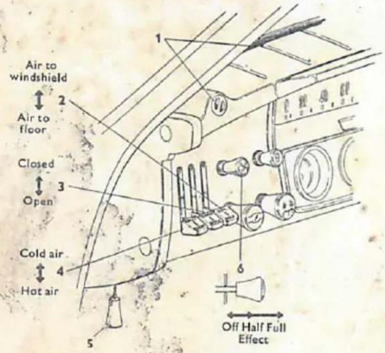
text_image
Air to windshield Air to floor Closed Open Cold air Hot air Off Half Full Effect
The car is equipped with covers for the two holes in the wheel housing walls behind the radiator. Do not forget to close the covers in winter and to remove them in summer. Through these steps the cooling system is adapted to the season and the proper engine temperature will be reached more quickly.
Safety Belt
Safety belt kits are stocked as spares and they are very easily installed as per the description enclosed. The rear attachment of the belt is located just under the quarter window, where the panel is reinforced. The other end of the belt is attached to the floor between the front seats.
Heavy Duty Rear Springs
If a Saab 95 is to be used frequently for very heavy transports, the rear suspension ought to be modified by fitting the extra strong coil springs, which are available as spare parts.

text_image
60 SAABLubrication Directions
Proper lubrication is very important for maintaining the car in good condition. It is cheaper to lubricate the car regularly and with first class lubricants than to pay for repairs caused by neglecting the lubrication directions.
The Lubrication Chart and fig. 34 on the following pages show the lubrication points on the Saab 95 and indicate the proper lubricants to be used, method of application and intervals between lubrications.
To check the oil level in the transmission, remove the inspection plug and check with a wire that the level is not lower than 5 mm ( 14 in.) under the inspection plug, which corresponds to a capacity of 2 liters (2 U.S. qts.). In general, SAE 90 EP is recommended throughout the year, but if the car is frequently left outdoors in very cold weather, SAE 80 EP should be used.
Non-freezing grease should be used for the steering gear to ensure the best possible functioning during the winter.
If the car is to be out of service for an extended period, it should first be thoroughly lubricated. To prevent corrosion of the engine, it should be prepared as follows:
- Remove air filter cover and filter insert.
- Start engine and run it at fairly high speed (3,000—3,500 rpm).
-
Pour a suitable rust inhibitor or engine oil SAE 40 or SAE 50 into the carburetor and let the engine take in oil until it stops. The quantity required is about 0.2 liters (1/2 U.S. pint). Note, that the accelerator should be kept in the same position until the engine is choked.
-
Switch off the ignition and replace filter.
If necessary, drain the cooling system and remove the battery, which should be stored at room temperature and be kept properly charged.
After this preparation, the engine should not be started until the car is to be used again.
Lubrication Chart
| Lubrication intervals | See fig. 34 | Lubrication points | Num-ber of | Lupricant | Method of lubrication | ||
| 1,500 km 1,000 miles | 3,000 km 2,000 miles | 12,000 km 8,000 miles | |||||
| × | 1 | Upper & lower ball joints, L & R | 4 | Universal or chassis grease | Grease gun | ||
| × | 2 | Drive shaft, outer joint, L & R | 2 | —"— | —"— | ||
| × | 3 | Drag rod ends | 2 | —"—1 | —"— | ||
| × | 4 | Steering gear | 1 | —"—1 | —"— | ||
| × | 5 | Distributor gear | 1 | —"— | —"— | ||
| × | 6 | Inner drive shafts | 2 | Lubricating oil | Oil can | ||
| × | 7 | Accelerator | 5 | "—"— | —"— | ||
| × | 8 | Hydraulic brake system | 1 | SAE 70 R 12 | Check level | ||
| × | 9 | Pedals | 3 | Lubricating oil | Oil can | ||
| × | 10 | Hinges and locks3 | 9 | —"— | —"— | ||
| × | 11 | Brake levers | 3 | —"— | —"— | ||
| × | 12 | Distributor shaft | 2 | —"— | —"— | ||
| × | 13 | Distributor cam asse | 2 | Bosch Ft 1 v 4 | Grea | ||
| × | 14 | Transmission | 1 | SAE 90 EP5 | Oil | ||
| × | 15 | Speedometer cable | 1 | SAE 10 | Oil e | ||
| × | — | Rear shock absorbers | 2 | Shock abs. oil | Che | ||
| Approx. 25,000 km (16,000 miles) Approx. 50,000 km (32,000 miles) —"— —"— When fueling | 16 | Heater fan motor bearings | 2 | SAE 10 | Oil ce | ||
| 17 | Fan shaft bearings | 2 | Universal or ball bearing grease | p | |||
| 18 | Front wheel bearings | 2 | —"— | ||||
| 19 | Rear wheel bearings | 2 | —"— | ||||
| 20 | Engine | 1 | Saab Oil or other two stroke oil7 | ||||
1 Alt. Non-freezing lubricant. See page 61.
- Lockheed HD 103 or equivalent.
3 The rollers and striker plates should be greased
with paraffin wax and the door stoppers with
Vaseline.
4 First oil change at 2,500—3,000 km (1,500—2,000
miles) with subsequent check every 3,000 km
(2,000 miles).
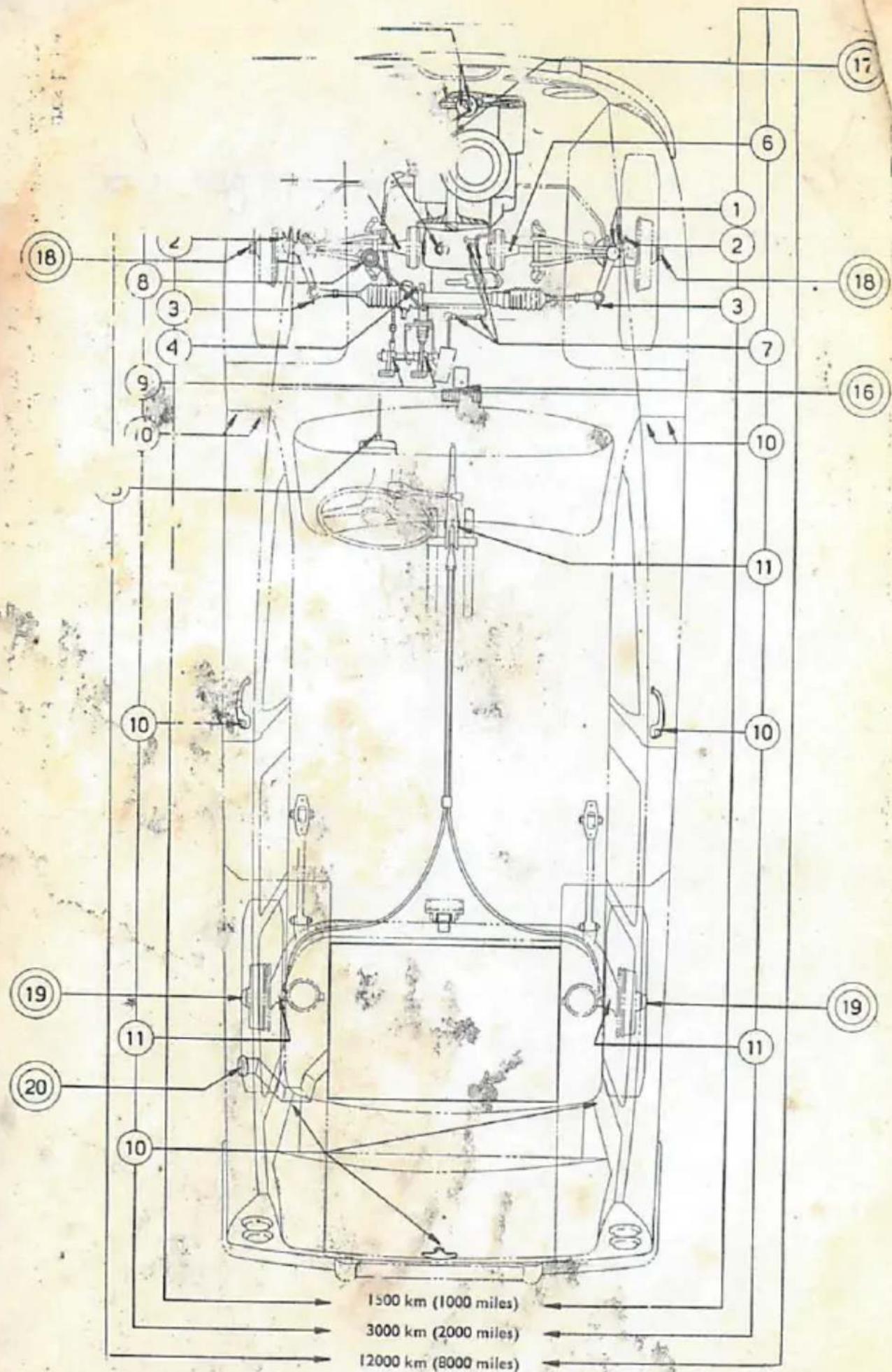
text_image
Technical diagram of a vehicle's internal components with numbered parts and distance annotations in kilometers.Fig. 34. Lubrication Points. The numbers refer to the Lubrication Chart.
NOTES
2/19/44 - trade one Sobaro foe one Sobaro + 100 -
natural_image
Ancient manuscript with weathered paper and scattered dark specks, no legible text or symbolsDon't Forget
I To add oil when buying gasoline, see below.
2 To check coolant in radiator.
3 To check electrolyte level in battery.
4 To grease the car (see Lubrication Chart.)
ENGINE LUBRICATION RECOMMENDATIONS
Your Saab 95 is lubricated by adding oil to the gasoline tank when you buy fuel.
To insure long trouble free engine life, only high quality two cycle oil of either 30 or 40 weight viscosity should be used when refueling the Saab automobile. When refueling at temperatures below freezing the oil should be premixed with an equal quantity of gasoline before adding to the tank.
To meet these requirements SAAB OIL has been made available through all authorized SAAB agencies in single quarts or in handy six-pack containers. Premixing is not required with the use of SAAB oil, due to its special formulation to facilitate mixing.
Break-in (First 2000 miles) . . . Whenever refueling pour one quart of oil into gas tank, followed by SIX gallons of gasoline.
After Break-In . . . Pour one quart of oil into gas tank, then add approximately SEVEN to EIGHT gallons of gasoline. During the next few thousand miles avoid application of full throttle for extended periods of time.
USE ONLY SAAB ORIGINAL SPARE PARTS
Crankshafts and engines, reconditioned by the factory, are stocked as spares. The replacement system saves time and the prices are so low that extensive repairs as a rule are not profitable.