Axcor Wash 600 CL3000 - Lighting Claypaky - Free user manual and instructions
Find the device manual for free Axcor Wash 600 CL3000 Claypaky in PDF.

User questions about Axcor Wash 600 CL3000 Claypaky
0 question about this device. Answer the ones you know or ask your own.
Ask a new question about this device
Download the instructions for your Lighting in PDF format for free! Find your manual Axcor Wash 600 CL3000 - Claypaky and take your electronic device back in hand. On this page are published all the documents necessary for the use of your device. Axcor Wash 600 CL3000 by Claypaky.
USER MANUAL Axcor Wash 600 CL3000 Claypaky
natural_image
Line drawing of a portable device with mesh chamber and control panel (no text or symbols)| INDEX | |
| Page | Contents |
| 2 | 1. Safety information |
| 3 | 2. Unpacking and preparation |
| 4 | 3. Installation and start-up |
| 4 | 3.1 Installing the fixture |
| 4 | 3.2 Connecting to manis supply |
| 5 | 3.3 Connecting the control signal line: DMX / Art-Net |
| 5 | 3.4 Switching on the fixture and basic SetUp |
| 7 | 4. Maintenance |
| 7 | 4.1 Opening the covers |
| 8 | 4.2 Periodical cleaning |
| 9 | 4.3 Effects module removal |
| 14 | 4.4 Cleaning of the filters |
| 16 | 4.5 Battery removal |
| 17 | 4.6 Frost filter removal |
| 17 | 4.7 Accessories |
| 18 | 5. Dimensions |
Congratulations on choosing a Claypaky product!
We thank you for your custom.
Please note that this product, as all the others in the rich Claypaky range, has been designed and made with total quality to ensure excellent performance and best meet your expectations and requirements.
1. SAFETY INFORMATION
EN
SAFETY INFORMATION
IMPORTANT: Claypaky recommends you carefully read and keep the safety information on this product, also available in digital format at the following link:
www.claypaky.com
Ref: [FIS00W - Safety Information Axcor 600 series]
IT
Rif: [FIS00W - Safety Information Axcor 600 series]
DE
Ref: [FIS00W - Safety Information Axcor 600 series]
ES
Ref: [FIS00W - Safety Information Axcor 600 series]
FR
CONSIGNES DE SÉCURITÉ
text_image
SAFETY INFORMATION Read carefully CLAYPAKY HOW TO GET YOUR USER MANUAL CLAYPAKY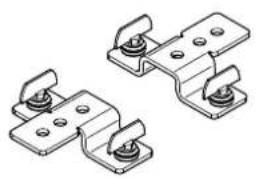
natural_image
Technical illustration of two mechanical bracket components with mounting holes (no text or symbols)2 x 183102/805

Packing contents - Fig. 1
2

text_image
2 LOCKED UNLOCKED
text_image
90° 90° °06 °06
text_image
3 45° 45° 45° 45° 45° 45°PAN Mechanism Lock and Release (every 90°) - Fig. 2
TILT Mechanism Lock and Release (every 45°) - Fig. 3
3. INSTALLATION AND START-UP
3.1 Installing the fixture
4
natural_image
Technical line drawing of a mechanical device with a cylindrical lens and attached base (no text or symbols)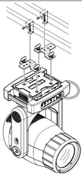
natural_image
Technical line drawing of a mechanical device with clamps and a base plate (no text or symbols)
natural_image
Technical line drawing of a mechanical device with mounting brackets and a cylindrical component (no text or symbols)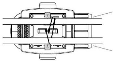
natural_image
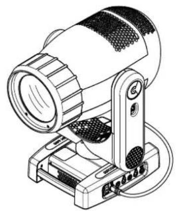
Technical line drawing of a mechanical assembly with no visible text or symbolsInstalling the projector - Fig. 4
The projector can be installed on the floor resting on special rubber feet, on a truss or on the ceiling or wall.
WARNING: with the exception of when the projector is positioned on the floor, the safety cable must be fitted. (Cod. 105041/001 available on request).
This must be securely fixed to the support structure of the projector and then connected to the fixing point at the centre of the base.
3.2 Connecting to manis supply
text_image
5 QXCOR H TBD N THU ELENEST 2 1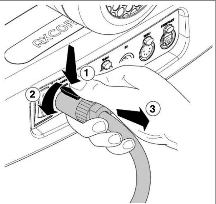
text_image
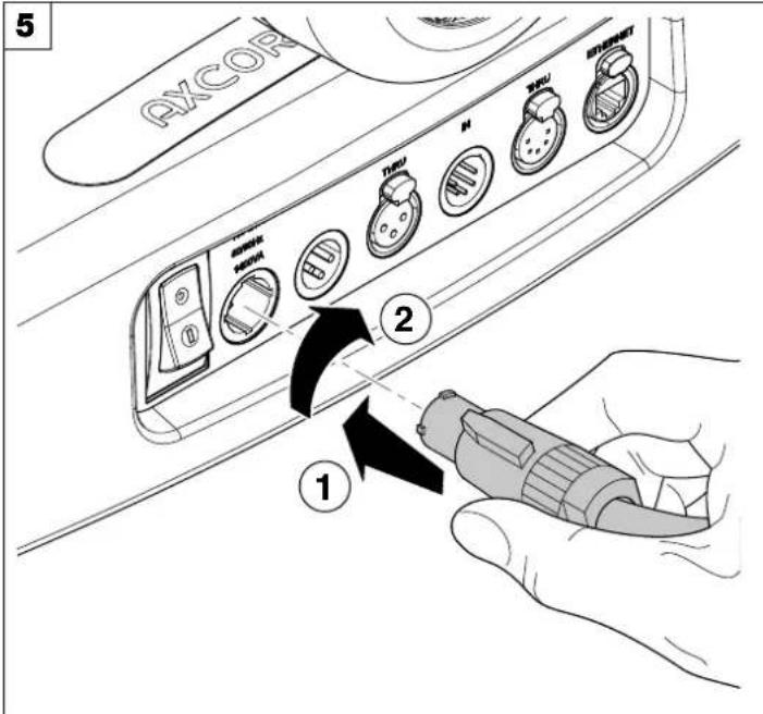
AXCOR 1 2 3Connecting and disconnecting power cable - Fig. 5
6

text_image
MainsConnecting to the mains supply - Fig. 6
3.3 Connecting the control signal line: DMX / Art-Net
7

text_image
DMX 512 3 PIN SIGNAL - 1 SCREEN + SIGNAL + DMX 512 5 PIN SCREEN + SIGNAL + SIGNAL +Connecting to the control signal line (DMX) - Fig. 7
Use a cable conforming to specifications EIA RS-485: 2-pole twisted, shielded, 120Ohm characteristic impedance, 22-24 AWG, low capacity. Do not use microphone cable or other cable with characteristics differing from those specified. The end connections must be made using XLR type 3 or 5 pin male/female connectors. A terminating plug must be inserted into the last projector with a resistance of 120Ohm (minimum 1/4 W) between terminals 2 and 3.
IMPORTANT: The wires must not make contact with each other or with the metal casing of the connectors. The casing itself must be connected to the shield braid and to pin 1 of the connectors.
3.4 Switching on the fixture and basic SetUp
8

text_image
Fixture ID Dmx Address 2 1 Warning Message LAVPAKY OKSwitching on the projector - Fig. 8
Press the switch. The projector starts resetting the effects. At the same time, the following information scrolls on the display:

Model Axcor 600
Firmware
Version X.X.X
Date - Hour
xxx (Fixture ID)
Dmx Address xxx
System errors
E: ......
W: ....
On conclusion of resetting in case of absence of the dmx signal, Pan and Tilt move to the "Home" position (Pan 128 bit - Tilt 128 bit). The control panel (Fig. 8) has a display and buttons for the complete programming and management of the projector menu. The display can be in one of two conditions: rest status and setting status. When it is in the rest status, the display shows the projector's DMX address and the Fixture ID address (if set).
During menu setting status, after a wait time (about 30 seconds) without any key having been pressed, the display automatically returns to rest status. It should be noted that when this condition occurs, any possible value that has been modified but not yet confirmed with the OK key will be cancelled.
9

text_image
LAPAKY OK 28Reversal of the display - Fig. 9
To activate this function, press UP ⬆ and DOWN ⬇ keys simultaneously while the display is in the rest mode. This status will be memorised and maintained even for the next time it will be switched on. To return to the initial state, repeat the operation all over again.
Setting the projector starting address
On each projector, the starting address must be set for the control signal (addresses from 1 to 512).
The address can also be set with the projector switched off.
Setting the projector Fixture ID
On each projector, the Fixture ID address must be set for an easy identification of the fixtures in an installation (ID from 1 to 255).
The Fixture ID address can be set with the projector switched off.
Functions of the buttons - Using the menu
flowchart
graph TD
    A["OK"] --> B["Arrow 1"]
    A --> C["Arrow 2"]
    A --> D["Arrow 3"]
    A --> E["Arrow 4"]

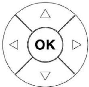
Confirms the displayed value, or activates the displayed function, or enters the successive menu.

Decreases the value displayed (with auto-repetitions) or passes to the next item in the menu.

Increases the value displayed (with auto-repetitions) or passes to the previous item in a menu.

Return to the top level

Commute from units, tens, hundreds, in the "Address", "Fixture ID" and "Calibration" menù.
RIGHT
USING THE MENU:
1) Press OK once – “Main Menu” appears on the display.
2) Use the UP ⬆ and DOWN ⬇ keys to select the menu to be used:
- Setup (Setup Menu): To set the setting options.
- Option (Option Menu): To set the operating options
- Informations (Informations Menu): To read the counters, software version and other information.
- Manual Control (Manual control Menu): To trigger the test and manual control functions.
- Test (Test Menu): To check the proper functioning of effects
- Advanced (Advanced Menu): Access to the "Advanced menu" is recommended for a trained technical personnel.
3) Press OK to display the first item in the selected menu.
4) Use the UP ⬆ and DOWN ⬇ keys to select the MENU items.
Setting addresses and options with the projector disconnected
The projector's DMX address, as well as other possible operating options, can also be set when the appliance is disconnected from the electricity supply. All that is needed is to press OK to momentarily activate the display and thus access the settings. Once the required operations have been carried out, the display will switch off again after a wait time of 30 seconds.
4. MAINTENANCE
4.1 Opening the covers
1011

text_image
1/4 Turn ①
natural_image
Technical line drawing of a mechanical device with labeled components (no text or symbols present)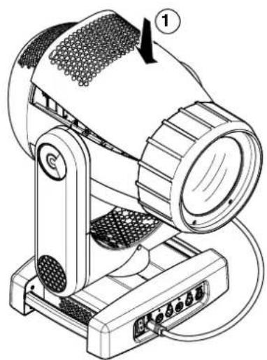
natural_image
Technical line drawing of a mechanical device with labeled component (1), no readable text or symbols present.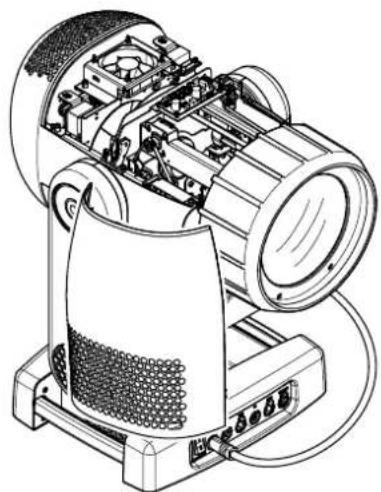
natural_image
Technical line drawing of a mechanical device with internal components and wiring (no text or symbols)
text_image
1/4 Turn 1 2
text_image
CLICK!!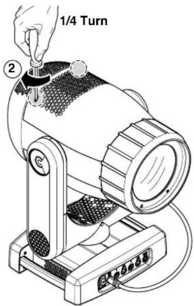
text_image
1/4 Turn ②Locking and releasing Pan and Tilt movements - Refer to the instructions in the UNPACKING AND PREPARATION section.
Opening the head covers - Fig. 10.
Closing the head covers - Fig. 11.
4.2 Periodical cleaning
12
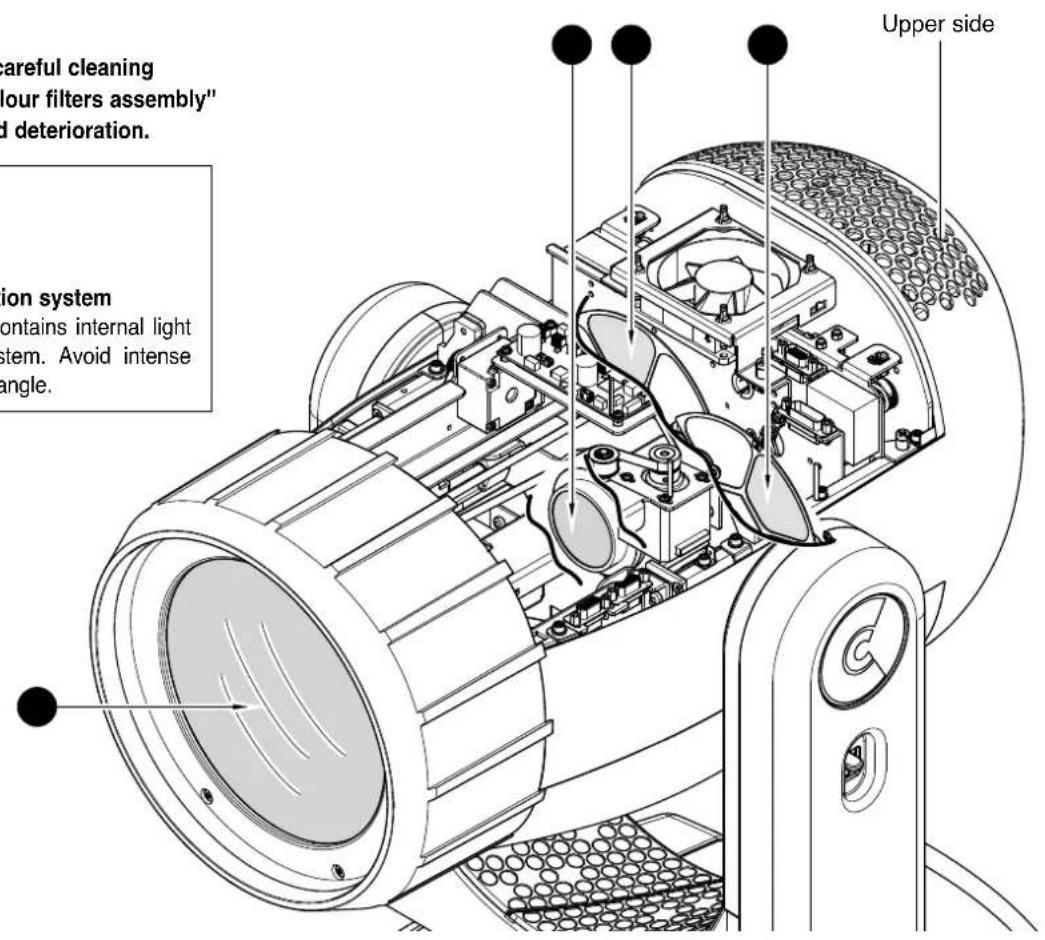
NOTE: keep a careful cleaning of the "CMY/colour filters assembly" to prevent rapid deterioration.

Light collimation system
This product contains internal light collimation system. Avoid intense light from any angle.
text_image
Careful cleaning four filters assembly" d deterioration. ion system contains internal light system. Avoid intense angle. Upper side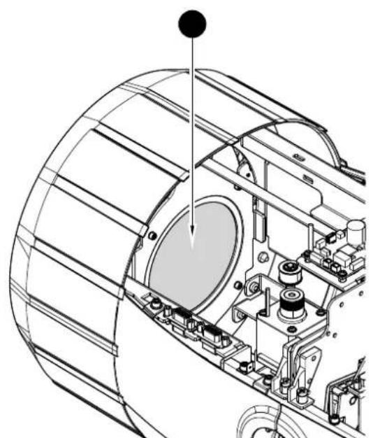
natural_image
Technical line drawing of a mechanical assembly with no visible text or symbols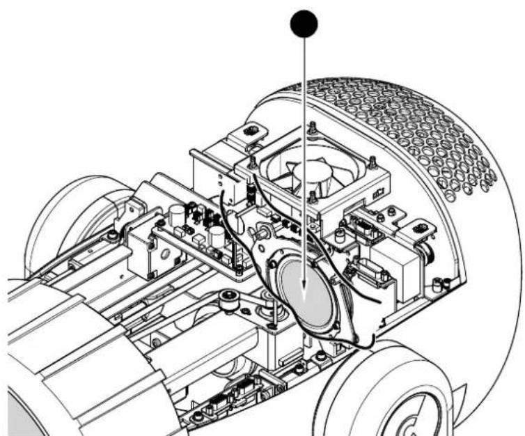
natural_image
Technical line drawing of a vehicle chassis with internal components and a sensor array (no text or symbols)Periodical cleaning - Fig. 12
To ensure optimal operation and performance for a long time it is essential to periodically clean the parts subject to dust and grease deposits. The frequency with which the following operations are to be carried out depends on various factors, such as the amount of the effects and the quality of the working environment (air humidity, presence of dust, salinity, etc.).
Use a soft cloth dampened with any detergent liquid for cleaning glass to remove the dirt from the reflectors, from the lenses and filters. It is recommended that the projector undergoes an annual service by a qualified technician for special maintenance involving at least the following operations:
- General cleaning of internal parts.
- Restoring lubrication of all parts subject to friction, using lubricants specifically supplied by Claypaky.
- General visual check of the internal components, cabling, mechanical parts, etc.
- Electrical, photometric and functional checks; eventual repairs.
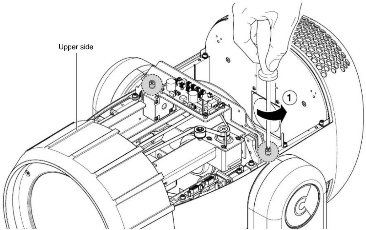
4.3 Effects module removal
13

text_image
Upper side 1 2 3Extraction of the effect modules: Preliminary operations - Fig. 13.
NOTE:
- Do not disconnect wiring harnesses when the fixtures is switched-on, to avoid to damage electronic boards.
- Do not switch-on the fixtures with wiring harness disconnected.

Extraction of the effect modules: Preliminary operations - Fig. 14.
NOTE:
- Do not disconnect wiring harnesses when the fixtures is switched-on, to avoid to damage electronic boards.
- Do not switch-on the fixtures with wiring harness disconnected.
15
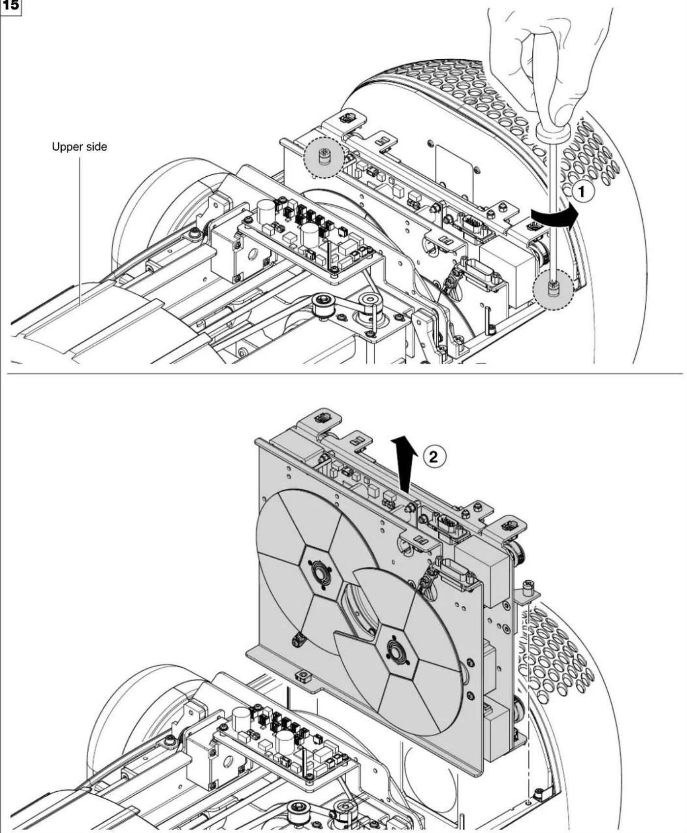
text_image
15 Upper side 1 2Extraction of the effect modules - Fig. 15.
IMPORTANT: Grasp the modules using the support structure and not the details which could get damaged.
Insertion of the effect modules: Repeat the operations indicated in Fig. 15, 16, 17 and 18 in reverse order.
16
text_image
Upper side 1
natural_image
Technical line drawing of a mechanical assembly with labeled components (no text or symbols present)Extraction of the effect modules - Fig. 16. IMPORTANT: Grasp the modules using the support structure and not the details which could get damaged. Insertion of the effect modules: Repeat the operations indicated in Fig. 15, 16, 17 and 18 in reverse order.
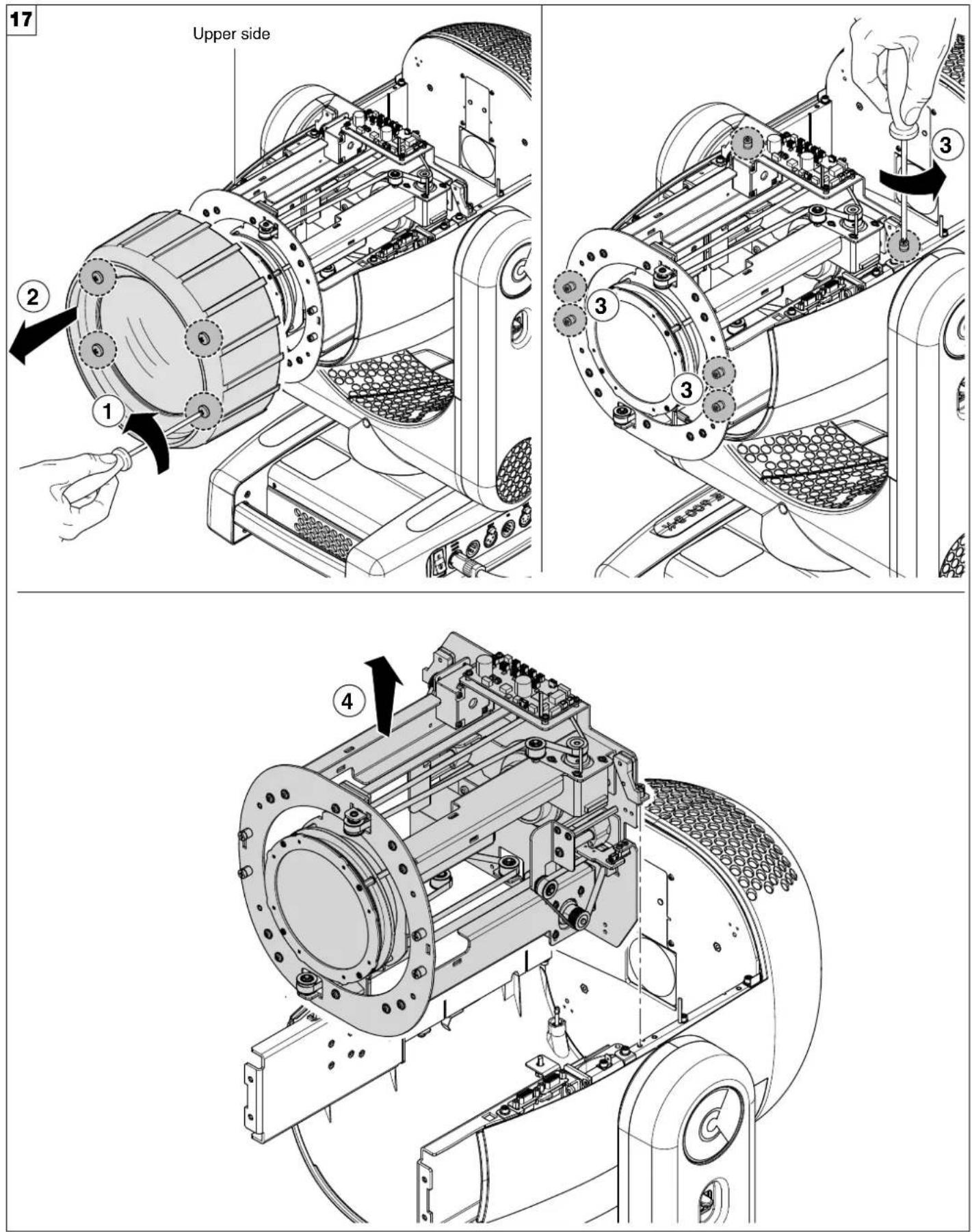
Extraction of the effect modules - Fig. 17.
IMPORTANT: Grasp the modules using the support structure and not the details which could get damaged.
Insertion of the effect modules: Repeat the operations indicated in Fig. 15, 16, 17 and 18 in reverse order.
4.4 - Cleaning of the filters
18

natural_image
Diagram of a mechanical device with labeled components and directional arrows indicating rotation or movement (no text or symbols present)
text_image
1/4 Turn 2
natural_image
Technical line drawing of a curved mechanical component with internal compartments and mounting brackets (no text or symbols)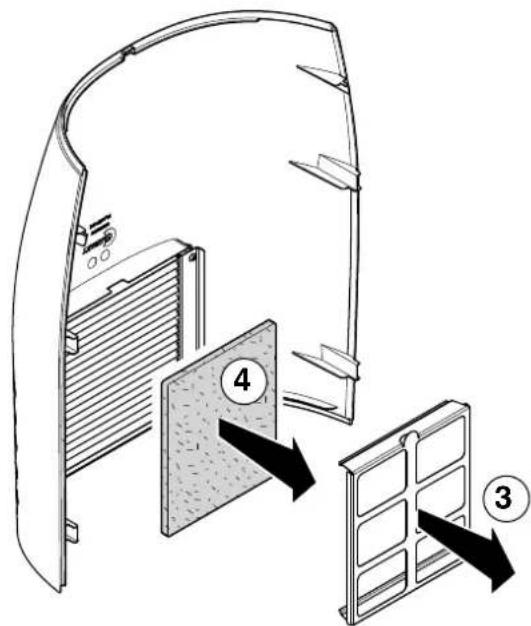
text_image
Diagram showing a door panel installation with labeled components and directional arrows indicating assembly or movement.
natural_image
Illustration of two hands using a tool to apply a spray or droplet onto a textured surface (no text or symbols)Cleaning of the filters - Fig. 18.
19

natural_image
Diagram of a handheld device with ports and control panel, showing directional arrows indicating motion (no text or symbols)
text_image
1/4 Turn ①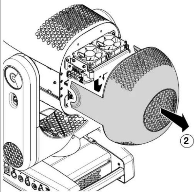
natural_image
Technical diagram of a mechanical device with internal components and a numbered label (2), showing no readable text or symbols.
text_image
Technical diagram showing a mechanical assembly with labeled components and directional arrows indicating movement or assembly.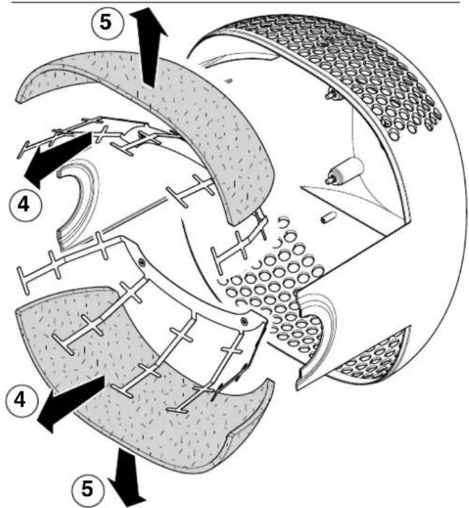
text_image
Technical diagram of a mechanical device with numbered components and directional arrows indicating motion or assembly.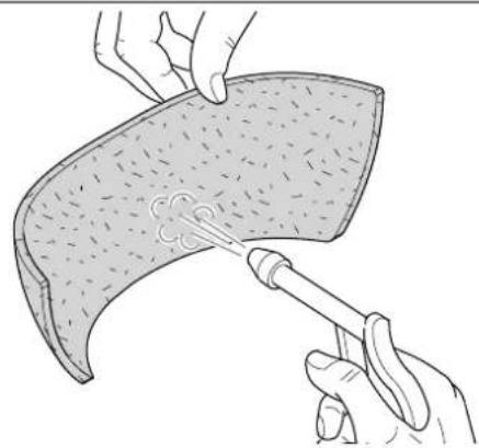
natural_image
Illustration of a hand using a pipette to apply liquid onto a curved surface (no text or symbols)Cleaning of the filters - Fig. 19.
4.5 Battery removal
20

text_image
20 1 RDCOR WIREN 600 RDCOR WIREN 600 2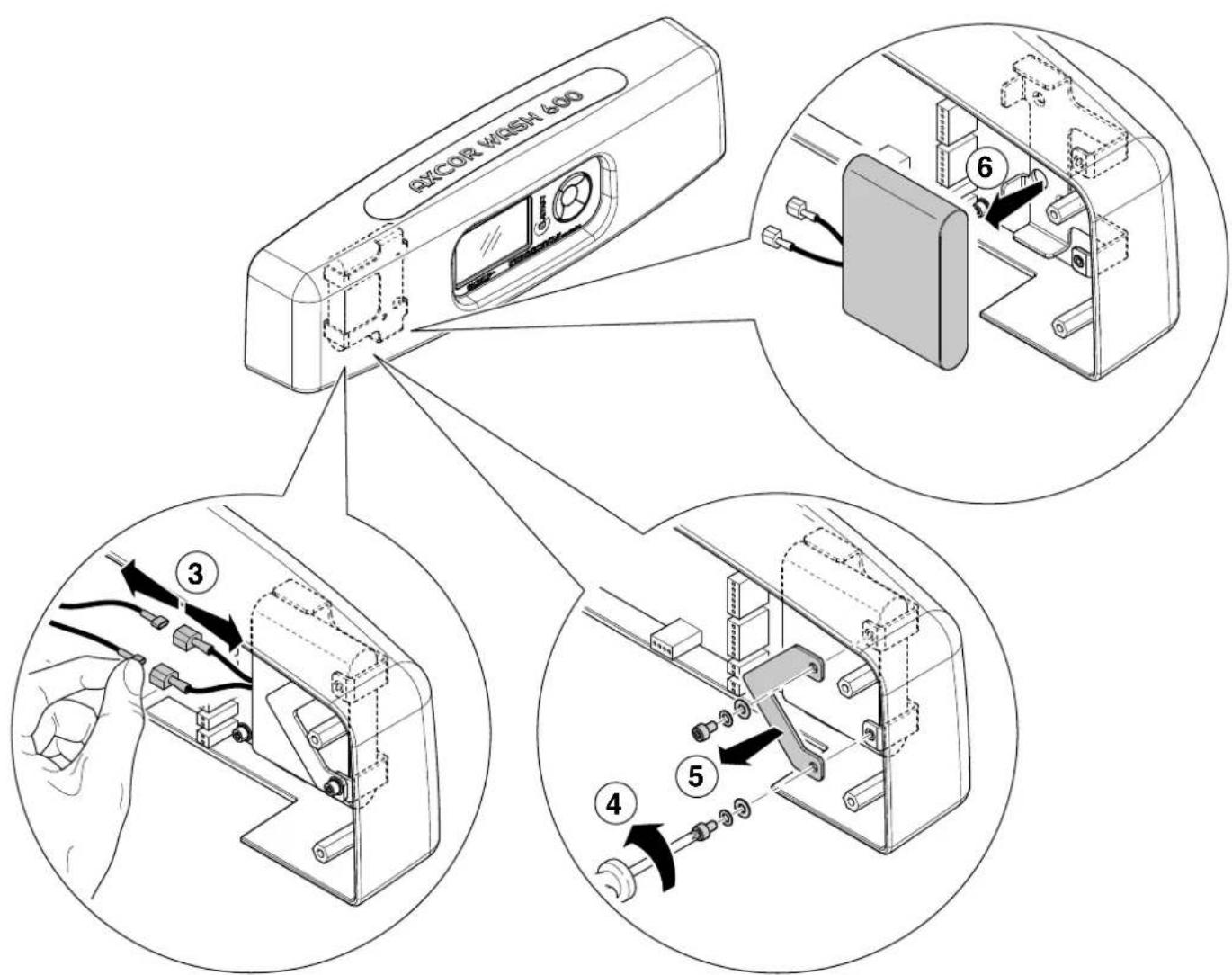
text_image
QXCOR W/OSH 600 ③ ④ ⑤
This product contains a rechargeable battery. To preserve the environment, please dispose the battery at the end of its life according to the regulation in force.
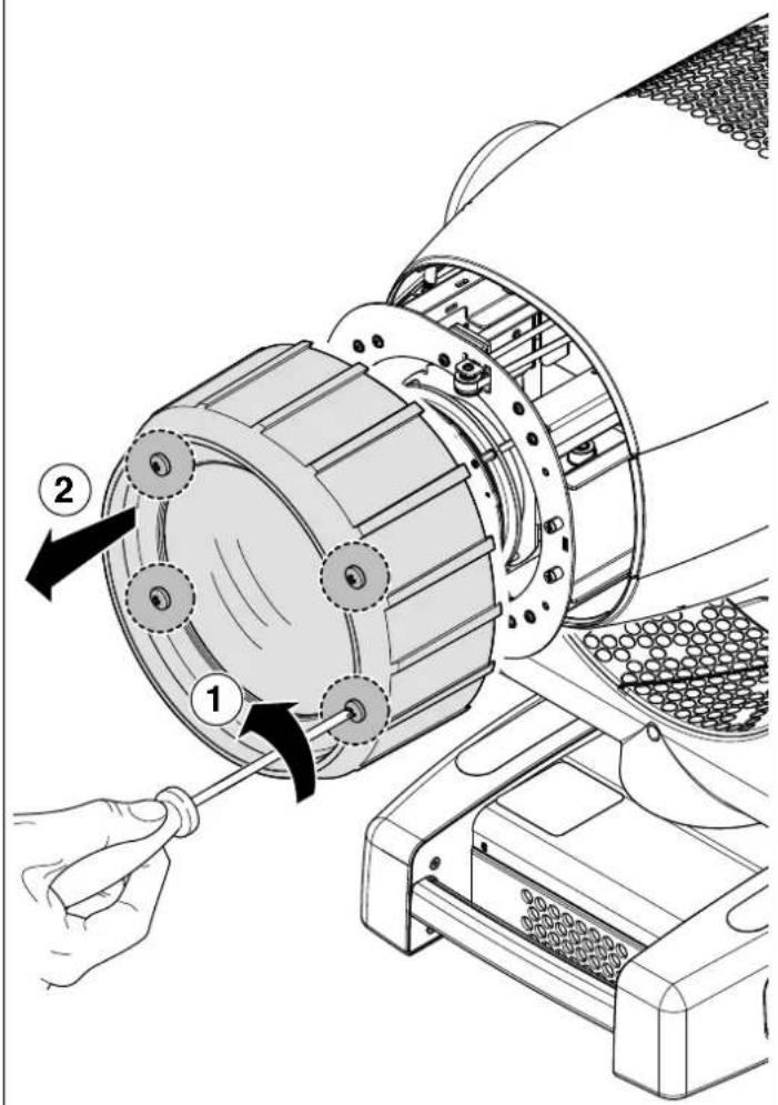
4.6 - Frost filter removal
21
text_image
Technical diagram of an electric motor assembly with labeled parts and directional arrows indicating components
text_image
Technical diagram showing mechanical assembly with numbered parts and directional arrows indicating components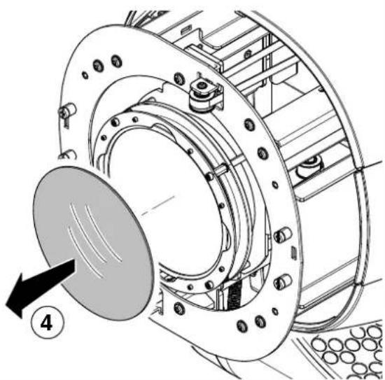
natural_image
Technical diagram of a mechanical assembly with a circular component and bolted parts, no visible text or symbolsFrost filter removal - Fig. 21.
4.7 - Accessories
22
CZ1000 - Fresnel Lens Kit CZ1001 - Clear Lens Kit

natural_image
Technical line drawing of a cylindrical mechanical component with ribbed texture (no text or symbols)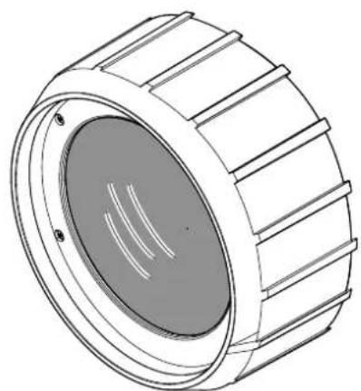
natural_image
Technical line drawing of a cylindrical mechanical component with ribbed texture (no text or symbols)Accessories - Fig. 22.
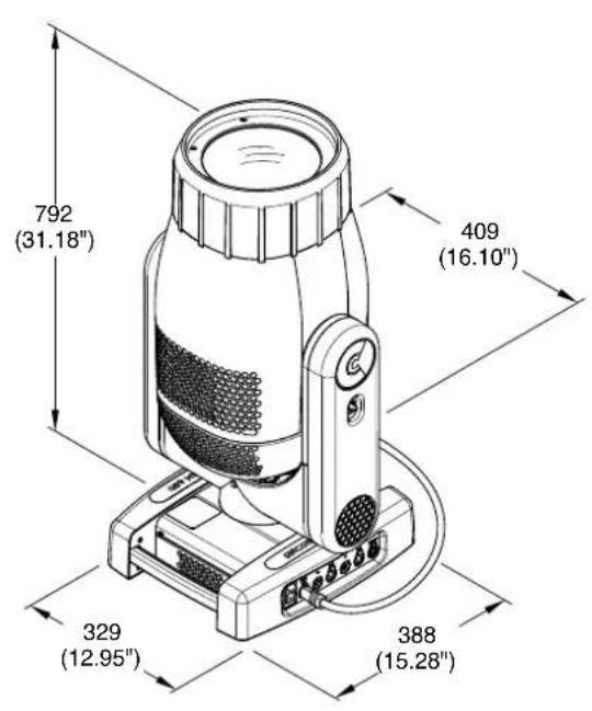
5. DIMENSIONS

text_image
621 (24.45") 578 (22.76") 636 (25.04")