M1435-EXP - Battery White Lightning - Free user manual and instructions
Find the device manual for free M1435-EXP White Lightning in PDF.

User questions about M1435-EXP White Lightning
0 question about this device. Answer the ones you know or ask your own.
Ask a new question about this device
Download the instructions for your Battery in PDF format for free! Find your manual M1435-EXP - White Lightning and take your electronic device back in hand. On this page are published all the documents necessary for the use of your device. M1435-EXP by White Lightning.
USER MANUAL M1435-EXP White Lightning
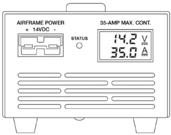
Model M1435-EXP 14-Volt 35-Amp Maximum Continuous

text_image
AIRFRAME POWER + 14VDC 35-AWP MAX. COAT. 142 Ω 350 Ω WHITE LIGHTNING AVIATION GROUND POWERIMPORTANT DISCLAIMERS & LIABILITY LIMITATIONS
As a condition for use, Audio Authority Corp. authorizes this device for use ONLY by aviation professionals, such as licensed pilots and maintenance technicians, knowledgeable about the aircraft's electrical system and batteries. Experimental/Amateur-Built aircraft electrical systems not only vary widely; they are unique. Many aircraft electrical systems also become altered from the original builder's configuration and these changes are often poorly documented in the aircraft records.
The concepts, recommendations, and instructions in this manual are necessarily general and make assumptions that do not apply to every aircraft and may not be correct for your particular aircraft. Incorrect use of this device has the potential to damage the GPU and/or aircraft components. This product also requires installation of electrical wiring to the airframe to function.
It is the operator's sole responsibility to read completely and fully understand this manual, plus all available documentation on their aircraft's electrical system design, to properly determine the appropriate use of this, or any, external power source. If you cannot do this, do not use this product. Instead, consult a qualified technician familiar with your specific aircraft type and configuration before connecting the GPU to your aircraft, or return it to the seller before using.
General Description and Application
The Model M1435-EXP Mini-GPU is a specialized switching-mode power supply designed to provide pilots and aviation maintenance professionals with a portable, affordable source of stable, high-current, noise-free DC power that replicates the in-flight electrical environment. Its rated output is 14 Volts DC up to 35 amps maximum continuous current. It is designed specifically for the owner/operator/maintainer of Experimental/Amateur-Built (E/AB) aircraft. The GPU's intended purpose is to energize aircraft's main electrical bus without using the battery or engine. It will safely provide continuous power for the most delicate electronics and airframe systems up to its full rated output.
| Typical Uses | ●power avionics for flight planning, familiarization, and training |
| ●update flight deck database and software | |
| ●troubleshooting and maintenance |
text_image
AIRFRAME POWER + 14VDC - STATUS 35-AMP MAX. CONT. 14.2 V 35.0 A
text_image
Mini-GPU by Audio Authority Corp Assembled in Lexington, KY USA MANUAL SHUT DOWN TIMER USB POWER FUSE ON OFFFRONT PANEL VIEW REAR PANEL VIEW
Special Features
- Color-coded, keyed SB-50 type output connections to prevent accidental voltage mismatch (Yellow designates 12/14 volt compatibility)
- Dual digital output meters for voltage and current load
●Front panel status indicator LED - Programmable auto-shutdown timer
- Dual USB power ports for mobile device charging
- QuietFiltered™ output for interference-free COM radio operation
●Auto protection/recovery from short circuit, reverse polarity, over voltage/load/temperature
Operating Conditions and Limitations
The M1435-EXP is internally fan-cooled and relies on unobstructed ventilation access for proper operation. The GPU should operate on a clean, hard surface so that debris cannot be ingested. Its design assumes a dry operating environment. If used outdoors, it is the operator's responsibility to ensure that the unit is not exposed to moisture.
The M1435-EXP is designed to provide airframe power only. It is not a battery charger. It does not monitor the state-of-charge of the aircraft battery. It is not suitable for engine starting.
Safety Precautions
- Do not use this or any electrical device near uncontained fuel or fuel vapors.
- Use in a well-ventilated area.
- Do not use in a wet environment.
- Do not use in the presence of open fuel containers or if you detect fuel vapors.
- Disconnect GPU from aircraft when not in use.
- Do not leave unattended while in use.
Special Considerations for Experiment/Amateur-Built (E/AB) Aircraft
E/AB aircraft typically differ from certified aircraft in several important ways that affect providing electrical power for ground operations:
- E/A-B aircraft are generally smaller with less complex design and systems.
- Certified aircraft are usually designed with a triggered external power receptacle that routes electrical power directly to the airframe and/or engine while bypassing the battery. E/A-B builders do not usually include an external power receptacle in their electrical wiring to reduce expense.
- Certified aircraft must conform to their type design. E/AB aircraft have no type design conformity requirements and can differ significantly from one aircraft to another. Builders are free to design and build the aircraft to suit their individual preferences.
To use a GPU, most E/AB aircraft will need to install the provided wiring kit to create an easily accessible electrical connection to the aircraft's main electrical bus.
External Power Wiring Techniques and Diagrams
Best practice for wiring an external power receptacle, whether for battery maintenance charging or airframe power, is to wire to the battery contactor, NOT directly to the battery. There are two options as to which side of the contactor for making the connection, each with trade-offs to consider:
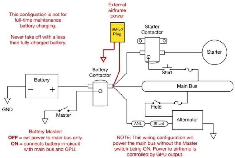
1) CONTACTOR OUTPUT – Wiring to the output side of the battery contactor provides direct access to the main bus for airframe power and bypasses the battery (unless the Battery Master Switch is ON).
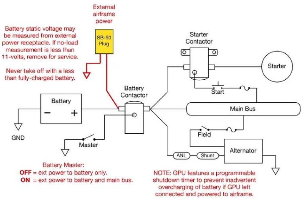
2) CONTACTOR INPUT – Wiring to the input side of the contactor provides direct access to the battery and cannot energize the airframe (unless the Battery Master Switch in ON).
Option 1 is the most appropriate and preferred for GPU operations. It keeps the battery out of the power circuit unless desired and deliberately enabled by turning the Battery Master switch ON.
Option 2 may be considered if the operator wants to provide an electrical connection for both the GPU and a full-time maintenance type battery charger (e.g., BatteryMINDer ^® ) from a single SB-50 plug. Option 2 also allows the GPU voltmeter to display no-load battery voltage when connected with the GPU power OFF. Some users may find this useful to assess the battery's state-of-charge.
Option 3, and the better approach if both GPU and maintenance charging are desired, is to install two separate SB-50 plugs, one to the battery side of the contactor for full-time maintenance charging; and another to the main bus side of the contactor for connecting a GPU for airframe power.
With E/AB aircraft it is ultimately the decision and at the sole discretion of the builder to evaluate the trade-offs for how and where to install in the receptacle(s) for GPU and/or battery charging in the aircraft. See the wiring diagrams below. The most common wiring scheme for external power receptacle is a shared connection for both battery charging and GPU airframe power, option diagram 2.
Wiring Diagrams for External Power Receptacle 12-Volt Experimental/Amateur-Built Aircraft
Option 1 – Output or Bus Side of Battery Contactor
flowchart
graph TD
    A["External airframe power"] --> B["SB-50 Plug"]
    B --> C["Battery Contactor"]
    C --> D["Main Bus"]
    D --> E["Alternator"]
    E --> F["Field"]
    F --> G["ANL"]
    G --> H["Shunt"]
    H --> I["Master"]
    I --> J["Battery"]
    J --> K["GND"]
    L["Start"] --> M["Starter Contactor"]
    N["External Airframe Power"] --> O["External Airframe Power"]
    P["External Airframe Power"] --> Q["External Airframe Power"]
    R["External Airframe Power"] --> S["External Airframe Power"]
    T["External Airframe Power"] --> U["External Airframe Power"]
    V["External Airframe Power"] --> W["External Airframe Power"]
    X["External Airframe Power"] --> Y["External Airframe Power"]
    Z["External Airframe Power"] --> AA["External Airframe Power"]
    AB["External Airframe Power"] --> AC["External Airframe Power"]
    AD["External Airframe Power"] --> AE["External Airframe Power"]
    AF["External Airframe Power"] --> AG["External Airframe Power"]
    AH["External Airframe Power"] --> AI["External Airframe Power"]
    AJ["External Airframe Power"] --> AK["External Airframe Power"]
    AL["External Airframe Power"] --> AM["External Airframe Power"]
    AN["External Airframe Power"] --> AO["External Airframe Power"]
    AP["External Airframe Power"] --> AQ["External Airframe Power"]
    AR["External Airframe Power"] --> AS["External Airframe Power"]
    AT["External Airframe Power"] --> AU["External Airframe Power"]
    AV["External Airframe Power"] --> AW["External Airframe Power"]
    AX["External Airframe Power"] --> AY["External Airframe Power"]
    AZ["External Airframe Power"] --> BA["External Airframe Power"]
    BB["External Airframe Power"] --> BC["External Airframe Power"]
    BD["External Airframe Power"] --> BE["External Airframe Power"]
    BF["External Airframe Power"] --> BG["External Airframe Power"]
    BH["External Airframe Power"] --> BI["External Airframe Power"]
    BJ["External Airframe Power"] --> BK["External Airframe Power"]
    BL["External Airframe Power"] --> BM["External Airframe Power"]
    BN["External Airframe Power"] --> BO["External Airframe Power"]
    BP["External Airframe Power"] --> BQ["External Airframe Power"]
    BR["External Airframe Power"] --> BS["External Airframe Power"]
    BT["External Airframe Power"] --> BU["External Airframe Power"]
    BV["External Airframe Power"] --> BW["External Airframe Power"]
    BX["External Airframe Power"] --> BY["External Airframe Power"]
    BZ["External Airframe Power"] --> CA["External Airframe Power"]
    CB["External Airframe Power"] --> CC["External Airframe Power"]
    DD["External Airframe Power"] --> EE["External Airframe Power"]
    FF["External Airframe Power"] --> DG["External Airframe Power"]
    DH["External Airframe Power"] --> DI["External Airframe Power"]
    DJ["External Airframe Power"] --> DK["External Airframe Power"]
    DL["External Airframe Power"] --> DM["External Airframe Power"]
    DN["External Airframe Power"] --> DE["External Airframe Power"]
    DF["External Airframe Power"] --> DG
    DG --> DW["External Airframe Power"]
Option 2 – Input or Battery Side of Contactor
flowchart
graph TD
    A["External airframe power"] --> B["SB-50 Plug"]
    B --> C["Battery Contactor"]
    C --> D["Main Bus"]
    D --> E["Alternator"]
    E --> F["Field"]
    F --> G["ANL"]
    G --> H["Shunt"]
    H --> I["Master"]
    I --> J["Battery"]
    J --> K["GND"]
    L["Battery static voltage may be measured from external power receptacle. If no-load measurement is less than 11-volts, remove for service."] --> M["Never take off with a less than fully-charged battery."]
    N["OFF = ext power to battery only."] --> O["ON = ext power to battery and main bus."]
    P["NOTE: GPU features a programmable shutdown timer to prevent inadvertent overcharging of battery if GPU left connected and powered to airframe."] --> Q["Start"]
    Q --> R["Starter Contactor"]
    R --> S["Starter"]
Installing the External Power Plug
- Locate a place near the battery contactor for the external power plug with convenient access, protected from heat and exposure, and permanently mount the SB-50 plug.
- Prepare two lengths of primary wire to connect the positive lug of the SB-50 plug to the battery contactor, and the negative lug to the airframe ground.
- Touch solder and install the connector lugs. Instructions are included with the wiring kit. It is recommended to install the included protective cover for the plug.
- Once the external power plug is installed, polarity tested and labeled, the GPU is ready to use.
Connecting GPU to Aircraft
- Connect the GPU AC input cord to a grounded power receptacle, 90-240VAC, 50-60Hz.
- Connect the output cable (dual 8-gauge cable with Yellow SB-50 plug on each end) to the GPU.
- Turn GPU power switch ON, observe as proper voltage stabilizes on the output display.
- Connect GPU output cable to SB-50 plug on the aircraft, observe that the airframe is energized and shows a stable load of less than 35 amps. If voltage or current load are not as expected, or GPU status indicator is flashing or red, disconnect the GPU from the airframe and investigate the problem.
SAFETY TIP: Using the GPU during preflight allows a thorough inspection of all systems and lights, without depleting the battery. In fact, if the battery is in-circuit, the GPU can provide a brief "top-off" charge for the aircraft battery!
Status Indicator
The GPU incorporates a status indicator between the volt/amp meter and the output connector. Indications are interpreted as follows:
| OFF | Power Switch OFF, or no AC input power |
| GREEN | ON or powered, normal operation |
| FLASHING GREEN | Auto-shutdown engaged |
| FLASHING RED | Fault condition – see troubleshooting table for more details |
Automatic Shutdown Timer
The M1435-EXP features a programmable timer to automatically shut down the GPU after a period of time in use, as selected by the user. This is to prevent the GPU from inadvertently being left on for an extended period and potentially overcharging the aircraft's battery, if in-circuit with the GPU.
A 10-position rotary switch on the back panel determines the duration of continuous operation. Each number represents 12 hour. This switch is factory set at 5 (2.5 hours); adjust with a small screwdriver. To disable the auto-shutdown feature, set the switch to the 0 position.
To reset the timer and restart the GPU after auto-shutdown, cycle the power switch OFF then back ON.
USB Mobile Device Charging
Two convenience USB charging ports are provided on the rear panel of the GPU. These provide a 5VDC output, up to 2A total combined, suitable for charging many portable devices like phones and speakers.
Troubleshooting
| PROBLEM / CONDITION | CAUSE | SOLUTION |
| GPU does not turn ONVolt/Amp meter OFF*Status indicator OFF | No AC input to GPU. | Verify power cord connections.Check AC input fuse. If blown, replace (only once). 1 extra fuse is contained in the fuse drawer.If fuse blows a second time, do not replace until GPU is repaired. See Limited Warranty statement for technical service contact information. |
| GPU displays voltage but no output to aircraft (zero amps)Status indicator GREEN | Faulty connection between GPU and aircraft electrical system. | Check connections from GPU to the aircraft's external power receptacle. |
| Volt/amp meter OFF*Status indicator FLASHING GREEN | Auto-shutdown timer expired. | Cycle power switch OFF, then back ON,to restart shutdown timer.Adjust timer settings if desired, or zero to disable shutdown timer. |
| Status indicator FLASHING REDVoltage drops to < 13 volts | Current overload. | Reduce load to less than 35 amps. |
| Status indicator FLASHING REDVolt/Amp meter OFF | Internal protection engaged.Over temperature, or Sustained overload. | Reduce load to less than 35 amps.Turn off aircraft equipment to reduce current draw.Cycle Power Switch OFF then ON again to reset. |
| Status indicator FLASHING REDGPU displays voltage but no output to aircraft (zero amps) | Internal protection engaged. | If cable connections are good, then turn power switch OFF.Disconnect DC output cord from aircraft external power receptacle. Wait for GPU meter to go OFF.Power switch ON. Meter ON.Reconnect to aircraft. |
* If there is battery voltage back feeding to the GPU from the aircraft, the voltmeter will display that condition, which may trigger the GPU into protection mode and not turn back on if power is interrupted. Follow instructions above for disconnecting from the aircraft and resetting the GPU to restore proper operation.
| SPECIFICATIONS | |
| Input | 90-240 Volts AC, 50-60 Hz, 5.3A @ 115VAC |
| Input fuse | 8A Littelfuse 617 Series. P/N 0617008.MXP |
| Output | 14.25 +/- 0.25 Volts DC, 35 amps maximum continuous |
| Output cable | 8 AWG dual conductor, SB-50 plug each end, yellow (12/14V) |
| Chassis dimensions | 4.13” H x 5.32” W x 13.4” L |
| Carry weight | 9.5 lbs., cables included |
| Carton dimensions | 6” H x 10” W x 16” L |
| Shipping weight | 11 lbs |
One Year Limited Warranty
Model M1435-EXP Mini-GPUs are warranted to the original purchaser to be free of defects in materials and workmanship for a period of one year from date of shipment. If you suspect a failure, please contact our service department for instructions or see our Service Policies online at www.audioauthority.com/page/Service_policy.
Service Department
Audio Authority Corporation
2048 Mercer Road, Lexington, KY 40511
Phone: 800-322-8346 (or 859-233-4599)
Email: support@audioauthority.com
Units received that are in-warranty will be repaired without charge. Units returned for service require a return authorization number and must be shipped freight prepaid. Units repaired under warranty will be returned freight prepaid via UPS ground or equivalent. A repair estimate will be provided for out-of-warranty repairs. This warranty is void for products that, in our opinion, have been subject to overload, moisture, accident, damage, alteration, misuse, abuse, or acts of nature.
THE SOLE AND EXCLUSIVE REMEDY UNDER THIS WARRANTY IS LIMITED TO REPAIR OR REPLACEMENT AS SPECIFIED ABOVE. THERE ARE NO OTHER WARRANTIES EXPRESSED OR IMPLIED. SPECIFICALLY, BUT WITHOUT LIMITATION, THERE ARE NO IMPLIED WARRANTIES OF MERCHANTABILITY OR FITNESS FOR A PARTICULAR PURPOSE. IN NO EVENT WILL AUDIO AUTHORITY BE RESPONSIBLE FOR ANY INCIDENTAL OR CONSEQUENTIAL DAMAGES ARISING FROM ANY DEFECT, OR FAILURE TO OPERATE PROPERLY, OR ARISING OUT OF ANY BREACH OF THE WARRANTY MADE HEREIN.
No person is authorized to give any other warranty or to assume any additional obligation or liability on behalf of Audio Authority Corporation, without its express written approval.

text_image
WHITE AVIATION TM LIGHTNING GROUND POWERAudio Authority Corp.
2048 Mercer Road
Lexington, KY 40511
800-322-8346 or 859-233-4599
support@audioauthority.com
AudioAuthority.com/aviation