NS-SPST2B - Speaker Stand INSIGNIA - Free user manual and instructions
Find the device manual for free NS-SPST2B INSIGNIA in PDF.

| Product Type | Speaker Stand |
| Brand | Insignia |
| Model | NS-SPST2B |
| Material | Steel |
| Height Adjustment Range | 24 to 36 inches |
| Maximum Load Capacity | 50 lbs (22.7 kg) |
| Base Dimensions (W x D) | 12 x 14 inches |
| Weight | 8 lbs (3.6 kg) |
| Color | Black |
| Cable Management | Yes, built-in channels |
| Assembly Required | Yes |
| Warranty | 1 year limited |
| Compatible Speaker Types | Bookshelf speakers up to 8 inches deep |
| Top Plate Size | 6 x 9 inches |
| Spikes/Feet Included | Yes, carpet spikes and rubber pads |
| Weight Capacity per Stand | 50 lbs (22.7 kg) |
| Number of Stands per Package | 2 |
| Recommended for | Home theater and stereo systems |
Frequently Asked Questions - NS-SPST2B INSIGNIA
User questions about NS-SPST2B INSIGNIA
0 question about this device. Answer the ones you know or ask your own.
Ask a new question about this device
Download the instructions for your Speaker Stand in PDF format for free! Find your manual NS-SPST2B - INSIGNIA and take your electronic device back in hand. On this page are published all the documents necessary for the use of your device. NS-SPST2B by INSIGNIA.
USER MANUAL NS-SPST2B INSIGNIA
natural_image
Technical line drawing of a vertical pole-mounted device with three inset views showing internal components (no text or symbols)INSIGNIA™
ENGLISH
Contents
Introduction 2
IMPORTANT SAFETY INSTRUCTIONS ....3
Features 4
Package contents 4
Dimensions....4
Parts....5
Hardware....5
Tools needed 5
Installation instructions....6
Specifications....18
ONE-YEAR LIMITED WARRANTY....19
ESPAÑOL
Índice
Congratulations on your purchase of a high-quality Insignia product. Your NS-SPST2B speaker stands are designed for reliable and trouble-free performance.
IMPORTANT SAFETY INSTRUCTIONS
SAVE THESE INSTRUCTIONS

CAUTION: Avoid potential personal injuries and property damage!
- Check your speaker's documentation to see if there are any special requirements for mounting your speaker.
- Read through these instructions completely to be sure you're comfortable with this installation process.
- Do not use this product for any purpose not explicitly specified by the manufacturer.
- The manufacturer is not responsible for damage or injury caused by incorrect assembly or use.
- If you do not understand these instructions or have doubts about the safety of the installation, assembly, or use of this product, contact Customer Service at 1-877-467-4289.
- The weight of your speakers must not exceed 4 lbs. (1.8 kg).
- This product contains small items that could be a choking hazard if swallowed. Keep these items away from young children!
Features
- 28 – 38 in. (71.1 – 96.5 cm) of height adjustment place your speakers where you want them
- Wide-ranging capability supports most popular speaker brands weighing up to 4 lbs. (1.8 kg)
- Integrated cable management system conceals and organizes your cables
- Wide, teardrop-shaped base guards against accidental tip-overs
• Durable steel frame adds strength and sturdiness
• For customer service, call: 1-877-467-4289
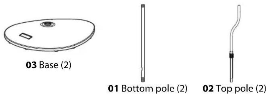
Package contents
- Speaker stands (2)
• Assembly hardware
-User Guide
Dimensions

text_image
28 - 38 in. (71.1 - 96.5 cm)Parts
text_image
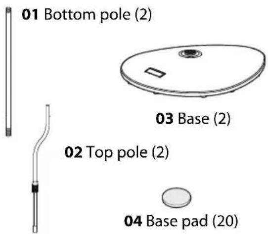
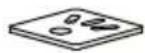
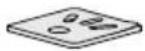
01 Bottom pole (2) 03 Base (2) 02 Top pole (2) 04 Base pad (20)
text_image
05 Adjusting nut (2) 07 Top plate (2)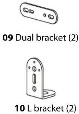
text_image
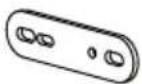
09 Dual bracket (2) 10 L bracket (2)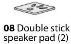
Hardware
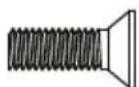
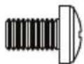
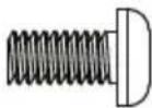
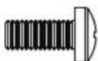
| # | Hardware Qty # Hardware | Qty | |
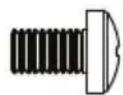
| 06 |  | 1/4-20 × 12 mm screw | |
| 11 |  | M5 × 15 mm screw | |
| 12 |  | M4 washer | |
| 13 |  | M4 x 7 mm screw | |
 M4 x 10 mm screw M4 x 10 mm screw | ||
 M5 × 12 mm screw M5 × 12 mm screw | ||
 1/4-20 × 1/2 in.screw 1/4-20 × 1/2 in.screw | ||
 Hook ‘n loopstrap Hook ‘n loopstrap |
Tools needed

Phillips screwdriver
Installation instructions
STEP 1 - Installing the base pads
You'll need
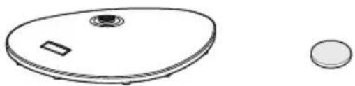
natural_image
Simple line drawing of a circular device with a small rectangular component and a circular base (no text or symbols)03 Base (2) 04 Base pad (20)
1 Carefully place the base (03) top-down on a cushioned, clean surface to protect it from scratches or damage.
2 Clean the 10 pad locations with denatured or isopropyl alcohol so that the base pads (04) will bond securely.
3 Remove the paper backing from the 10 base pads and place them on the pad locations on the base.

text_image
03 03 044 Repeat for the second base.
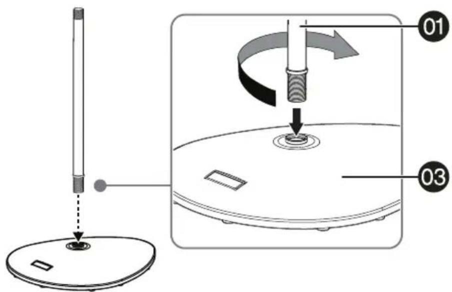
STEP 2 - Attaching the pole to the base and adjusting the height
You'll need
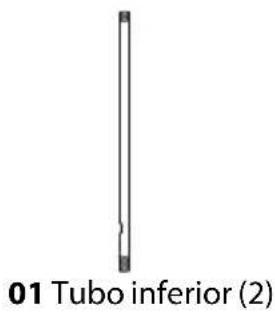
1 Carefully screw the bottom pole (01) clockwise into the base (03). Make sure that you screw the pole fully into the base to ensure stability.
text_image
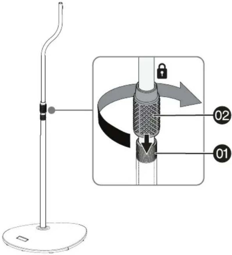
Diagram illustrating a mechanical or electrical setup with labeled components and directional arrows indicating motion or movement.2 Insert the top pole (02) into the bottom pole (01), lift it up or down to adjust to the height you want, then tighten the locking collar by turning it clockwise only until the top pole doesn't slip down.

text_image
02 locking collar 013 Adjust the top pole (02) so that the curved section is over the long section of the base (01), then fully tighten the locking collar by turning it clockwise.
text_image
Diagram illustrating the step-by-step installation of a stand-mounted device, showing lock operation and labeled parts 01 and 02.4 Repeat for the second speaker stand.
STEP 3 - Option 1: Attaching rear-mount speakers with threaded screw inserts
You'll need

10 L bracket (2)
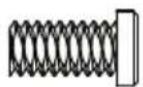
(11) M5 × 15 mm screw (2)

(12) M4 washer (2)

(13) M4 x 7 mm screw (2)
(14) M4 x 10 mm screw (2)
09 Dual bracket (2) 05 Adjusting nut (2)


(15) M5 × 12 mm screw (2 or 4)
(16) 1/4-20 × 1/2 in.
screw (2 or 4)
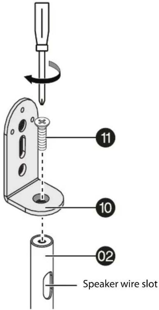
1 Attach the L bracket (10) to the top pole (02) with an M5 x 15 mm screw (11), with the speaker wire slot arranged as shown. Tighten securely.

text_image
Speaker wire slot 10 11 022 For speakers with a single hole in the back - Attach the speaker to the stand using an M4 washer (12) and an M4 x 7 mm screw (13), an M4 x 10 mm screw (14), or an M5 x 12 mm screw (15) or 1/4-20 x 1/2 in. screw (16) with no washer. Tighten securely, then skip to STEP 4 - Routing the speaker cables

text_image
10 12 13 or 14 15 or 163 For speakers with two holes in the back - Attach the dual bracket (09) to the speaker (threaded screw facing outwards) with two M5 x 12 mm screws (15), or two 1/4-20 x 1/2 in. screws (16). Tighten securely.
Attach the speaker/bracket assembly to the stand with an adjusting nut (05). Tighten securely then skip to STEP 4 - Routing the speaker cables on page 17.
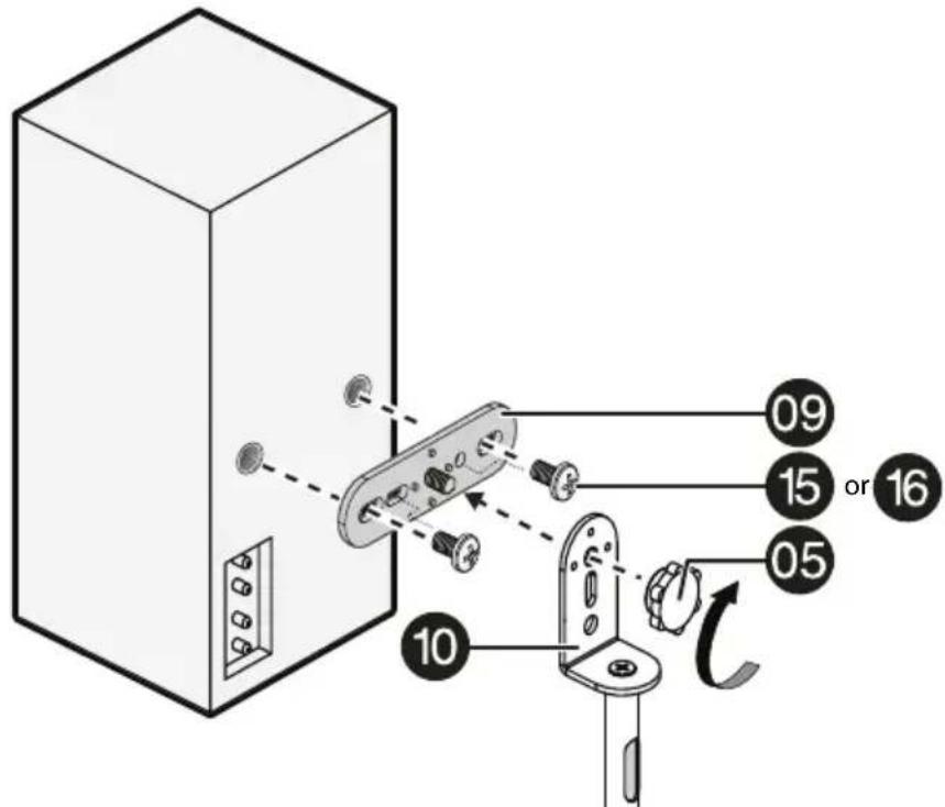
text_image
09 15 or 16 05 10STEP 3 - Option 2: Attaching rear-mount speakers with key-hole slots
You'll need
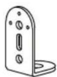
10 L bracket (2)
(11) M5 × 15 mm screw (2)

05 Adjusting nut (2)
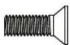
(06) 1/4-20 × 12 mm screw (2)
1 Attach the L Bracket (10) to the top pole (02) with an M5 x 15 mm screw (11), with the speaker wire slot arranged as shown. Tighten securely.
text_image
Speaker wire slot 10 11 022 Attach the (06) 1/4-20 × 12 mm screw to the L bracket (10) with an adjusting nut (05). Tighten securely.
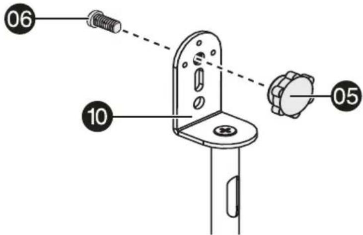
text_image
06 10 053 Attach the speakers to the stands by sliding the slots on the backs of the speakers over the (06) 1/4-20 × 12 mm screws, then skip to STEP 4 - Routing the speaker cables on page 17.
natural_image
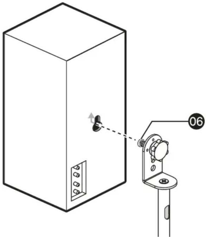
Technical line drawing of a cabinet with a switch and labeled component (no text or symbols present)STEP 3 - Option 3: Attaching bottom-mount speakers
You'll need
07 Top plate (2)
08 Double stick speaker pad (2)

(12) M4 washer (2)


(11) M5 × 15 mm screw (2)
(13) M4 x 7 mm screw (2)
(15) M5 × 12 mm screw (4)
(16) 1/4-20 × 1/2 in. screw (4)
Option A - Attach the top plates (07) to the top poles (02) with M5 x 15 mm screws (11), with the speaker wire slot arranged as shown. Tighten securely.

text_image
Speaker wire slot 02 07 111 If the speakers have mounting holes on the bottom, attach the speakers to the stands using option A or B. Otherwise, use option C.
2 Use M5 x 12 mm screws (15) or 1/4-20 x 1/2 in. screws (16). Tighten securely, then skip to STEP 4 - Routing the speaker cables on page 17.

text_image
07 15 or 16Option B - Use an M4 washer (12) and an M4 x 7 mm screw (13). Tighten securely, then skip to STEP 4 - Routing the speaker cables.

text_image
07 12 13Option C - Attach the double-stick speaker pads (08) to the top plates (07) by removing the paper covering the adhesive surface on the bottom of the pads and pressing them firmly onto the top plates. When the pads are firmly attached to the top plates, remove the paper covering the adhesive surface on the top of the double-stick speaker pads (08) and press the speakers firmly onto the pads.

text_image
Diagram showing a device assembly with labeled parts and directional arrows indicating movement or adjustment.STEP 4 - Routing the speaker cables
You'll need
Option A - Route the speaker cables by passing the wires into the speaker wire slot at the top of the top pole, then down the pole assembly and out the hole in the bottom pole and under the base.

natural_image
Technical diagram showing a vertical-mounted device with attached cable and a vertical-mounted stand, connected to a circular base (no text or symbols present)Option B - Run the wires on the outside of the poles and attach them to the poles using the hook 'n loop straps (17) as necessary.
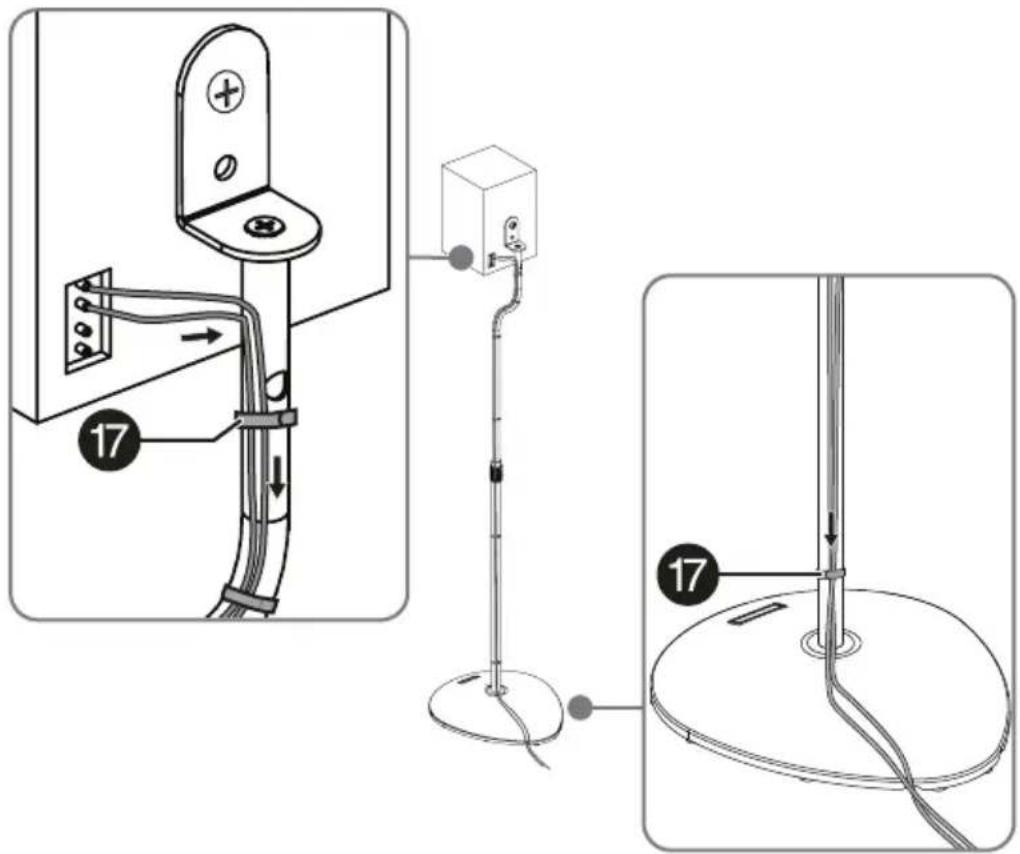
text_image
Technical diagram showing three-step installation of a device with labeled parts and connection pointsSpecifications
| Dimensions (H × W × D) 9.06 × 10.38 x 28 to 38 in. (23.01 × 26.36 x 71.12 to 96.5 cm) |
| Height adjustment range |
| Weight Gross: 11.1 lbs. (5 kg)Net: 9.8 lbs. (4.4 kg) |
| Supported weight 4 lbs. (1.8 kg) per speaker stand |
ONE-YEAR LIMITED WARRANTY
Definitions:
The Distributor* of Insignia branded products warrants to you, the original purchaser of this new Insignia-branded product ("Product"), that the Product shall be free of defects in the original manufacturer of the material or workmanship for a period of one (1) year from the date of your purchase of the Product ("Warranty Period").
For this warranty to apply, your Product must be purchased in the United States or Canada from a Best Buy branded retail store or online at www.bestbuy.comor www.bestbuy.ca and is packaged with this warranty statement.
How long does the coverage last?
The Warranty Period lasts for 1 year (365 days) from the date you purchased the Product. Your purchase date is printed on the receipt you received with the Product.
What does this warranty cover?
During the Warranty Period, if the original manufacture of the material or workmanship of the Product is determined to be defective by an authorized Insignia repair center or store personnel, Insignia will (at its sole option): (1) repair the Product with new or rebuilt parts; or (2) replace the Product at no charge with new or rebuilt comparable products or parts.
Products and parts replaced under this warranty become the property of Insignia and are not returned to you. If service of Products or parts are required after the Warranty Period expires, you must pay all labor and parts charges. This warranty lasts as long as you own your Insignia Product during the Warranty Period. Warranty coverage terminates if you sell or otherwise transfer the Product.
How to obtain warranty service?
If you purchased the Product at a Best Buy retail store location or from a Best Buy online website (www.bestbuy.com or www.bestbuy.ca), please take your original receipt and the Product to any Best Buy store. Make sure that you place the Product in its original packaging or packaging that provides the same amount of protection as the original packaging.
To obtain warranty service, in the United States and Canada call 1-877-467-4289. Call agents may diagnose and correct the issue over the phone.
Where is the warranty valid?
This warranty is valid only in the United States and Canada at Best Buy branded retail stores or websites to the original purchaser of the product in the country where the original purchase was made.
What does the warranty not cover?
This warranty does not cover:
- Food, beverage, and/or medicine loss/spoilage.
- Customer instruction/education
• Installation - Setup adjustments
- Cosmetic damage
- Damage due to weather, lightning, and other acts of God, such as power surges
- Accidental damage
- Misuse
- A b u s e
• Negligence - Commercial purposes/use, including but not limited to use in a place of business or in communal areas of a multiple dwelling condominium or apartment complex, or otherwise used in a place of other than a private home.
- Modification of any part of the Product, including the antenna
- Display panel damaged by static (non-moving) images applied for lengthy periods (burn-in).
• Damage due to incorrect operation or maintenance
- Connection to an incorrect voltage or power supply
- Attempted repair by any person not authorized by Insignia to service the Product
- Products sold "as is" or "with all faults"
- Consumables, including but not limited to batteries (i.e. AA, AAA, C etc.)
- Products where the factory applied serial number has been altered or removed
- Loss or Theft of this product or any part of the product
- Display panels containing up to three (3) pixel failures (dots that are dark or incorrectly illuminated) grouped in an area smaller than one tenth (1/10) of the display size or up to five (5) pixel failures throughout the display. (Pixel based displays may contain a limited number of pixels that may not function normally.)
- Failures or Damage caused by any contact including but not limited to liquids, gels or pastes.
REPAIR REPLACEMENT AS PROVIDED UNDER THIS WARRANTY IS YOUR EXCLUSIVE REMEDY FOR BREACH OF WARRANTY. INSIGNIA SHALL NOT BE LIABLE FOR ANY INCIDENTAL OR CONSEQUENTIAL DAMAGES FOR THE BREACH OF ANY EXPRESS OR IMPLIED WARRANTY ON THIS PRODUCT, INCLUDING, BUT NOT LIMITED TO, LOST DATA, LOSS OF USE OF YOUR PRODUCT, LOST BUSINESS OR LOST PROFITS. INSIGNIA PRODUCTS MAKES NO OTHER EXPRESS WARRANTIES WITH RESPECT TO THE PRODUCT, ALL EXPRESS AND IMPLIED WARRANTIES FOR THE PRODUCT, INCLUDING BUT NOT LIMITED TO ANY IMPLIED WARRANTIES OF AND CONDITIONS OF MERCHANTABILITY AND FITNESS FOR A PARTICULAR PURPOSE, ARE LIMITED IN DURATION TO THE WARRANTY PERIOD SET FORTH ABOVE AND NO WARRANTIES, WHETHER EXPRESS OR IMPLIED, WILL APPLY AFTER THE WARRANTY PERIOD. SOME STATES, PROVINCES AND JURISDICTIONS DO NOT ALLOW LIMITATIONS ON HOW LONG AN IMPLIED WARRANTY LASTS, SO THE ABOVE LIMITATION MAY NOT APPLY TO YOU. THIS WARRANTY GIVES YOU SPECIFIC LEGAL RIGHTS, AND YOU MAY ALSO HAVE OTHER RIGHTS, WHICH VARY FROM STATE TO STATE OR PROVINCE TO PROVINCE.
Contact Insignia:
1-877-467-4289
www.insigniaproducts.com
INSIGNIA is a trademark of Best Buy and its affiliated companies.
* Distributed by Best Buy Purchasing, LLC
7601 Penn Ave South, Richfield, MN 55423 U.S.A.
©2023 Best Buy. All rights reserved.
ESPAÑOL
Introducción
natural_image
Simple line drawing of a circular object with a central hole and a small rectangular cutout (no text or symbols)03 Base (2)
text_image
01 Tubo inferior (2)
text_image
02 Tubo superior (2)text_image
Diagram illustrating the step-by-step installation of a stand-mounted device, showing lock mechanism and component positioning.text_image
Diagram illustrating a mechanical or electrical component with labeled parts 01 and 02, showing a switch and lock mechanism.text_image
Diagram of a device panel assembly with numbered parts and directional arrows indicating assembly stepsnatural_image
Technical line drawing of a cabinet with a switch and labeled component (no text or symbols present)text_image
Diagram showing a device assembly with labeled parts and directional arrows indicating movement or transformation.natural_image
Technical diagram showing a vertical-mounted device with attached cable and a vertical-mounted stand, connected to a circular base (no text or symbols present)text_image
Technical diagram showing three-step installation of a door handle with cable routing and grounding points labeled 17.Especificaciones
| Dimensiones( Alto x Ancho x Profundia38φulg.) | 23.01 × 26.36 x 71.12 a 96.5 cm (9.06 × 10.38 x 28 |
| Rango de ajuste de altura 71.1 a | 96.5 cm (28 a 38 pulg.) |
| Peso Bruto: 5 kg (11.1 lb) | Neto: 4.4 kg (9.8 lb) |
| Peso admitido 1.8 kg (4 lb) por base de altavoz | |
GARANTÍA LIMITADA DE UN AÑO
Descripción:
INSIGNIA is a trademark of Best Buy and its affiliated companies.
Distributed by Best Buy Purchasing, LLC
7601 Penn Ave South, Richfield, MN 55423 U.S.A.
©2023 Best Buy. All rights reserved.
www.insigniaproducts.com