DS-MP7608HN/GW - Video recorder Hikvision - Free user manual and instructions
Find the device manual for free DS-MP7608HN/GW Hikvision in PDF.

| Product Type | Network Video Recorder (NVR) |
| Model | DS-MP7608HN/GW |
| Brand | Hikvision |
| Video Input | 8-channel IP camera input |
| Recording Resolution | Up to 12 MP per channel |
| Compression Format | H.265+/H.265/H.264+/H.264 |
| Storage Capacity | Supports up to 2 HDDs, each up to 10 TB |
| Dimensions (W x D x H) | Approx. 380 x 320 x 53 mm (without packaging) |
| Weight | Approx. 2.5 kg (without HDDs) |
| Power Supply | DC 12V, 2A (adapter included) |
| Power Consumption | < 15 W (without HDDs) |
| Network Interface | 1x RJ45 10/100/1000 Mbps |
| Audio Input/Output | 1x RCA input, 1x RCA output |
| Alarm Input/Output | 4x alarm input, 1x alarm output |
| Remote Access | Via Hik-Connect app or web browser |
| Recording Modes | Continuous, scheduled, motion detection, alarm trigger |
| Playback | Simultaneous playback of up to 8 channels |
| Backup | USB flash drive, eSATA, network download |
| Maintenance | Clean dust with dry cloth; ensure proper ventilation |
| Safety | Overvoltage protection; use only supplied adapter |
| Spare Parts / Repairability | HDD replacement; contact Hikvision support for other repairs |
Frequently Asked Questions - DS-MP7608HN/GW Hikvision
User questions about DS-MP7608HN/GW Hikvision
0 question about this device. Answer the ones you know or ask your own.
Ask a new question about this device
Download the instructions for your Video recorder in PDF format for free! Find your manual DS-MP7608HN/GW - Hikvision and take your electronic device back in hand. On this page are published all the documents necessary for the use of your device. DS-MP7608HN/GW by Hikvision.
USER MANUAL DS-MP7608HN/GW Hikvision
natural_image
Abstract graphic with geometric shapes and a red square, featuring a white globe and hand icon (no text or symbols)TABLE OF CONTENTS
Chapter 1 Panel Introducon ....8
1.1 Front Panel 8
1.2 Rear Panel....9
Chapter 2 Installaon and Connecons....11
2.1 Environment.... 11
2.2 Install HDD....11
2.3 Install SIM Card....15
2.4 Install SD Card....17
2.5 Alarm Input/Output Connecon 19
2.5.1 Alarm Input Connecon 19
2.5.2 Alarm Output Connecon.... 20
2.6 Sensor-in Wiring 20
2.7 Power Cord Wiring 20
2.7.1 Shutdown Delay.... 20
2.7.2 Timed Shutdown 21
Chapter 3 Start Up Device 23
3.1 Startup....23
3.2 Acvaon.... 23
Chapter 4 Network....25
4.1 Set Local Network....25
4.2 Connect Wireless Network 25
4.2.1 3G/4G Dialing....25
4.2.2 Set Wi-Fi 26
4.2.3 Set Wi-Fi AP 27
4.3 Firewall Setngs 28
Chapter 5 IP Camera Management....30
5.1 Acvate IP Camera....30
5.1.1 Auto Acvaon 30
5.1.2 Manual Acvaon.... 30
5.2 Add IP Camera 32
5.2.1 Quick Add 32
5.2.2 Manual Add 32
5.2.3 Edit Protocol 33
5.3 Edit IP Camera 33
5.4 Delete IP Camera 34
Chapter 6 Camera Management .... 35
6.1 Basic Image Settings 35
6.1.1 Set OSD Parameters 35
6.1.2 Set Image Parameters.... 35
6.2 Set Privacy Mask....36
6.3 Set Mirror Type.... 37
Chapter 7 Live View ...... 39
Mobile Network Video Recorder User Manual
7.1 Preview Settings 39
7.2 Set Camera Order 39
7.3 Right-Click Menu 41
7.4 PTZ Operation 41
7.4.1 Configure PTZ Settings 41
7.4.2 PTZ Control Panel 42
Chapter 8 Storage 43
8.1 Storage Settings 43
8.1.1 Format HDD 43
8.1.2 Configure Overwrite 43
8.1.3 Configure Picture Partition ____ 44
8.1.4 View S.M.A.R.T. Information 44
8.2 Recording Settings 45
8.2.1 Configure Record Settings 45
8.2.2 Configure Motion Detection Recording 47
8.2.3 Configure Alarm Triggered Recording 47
8.2.4 Configure Alarm Terminal
8.2.5 Configure Schedule 49
8.3 Sensor-in Settings
Chapter 9 Playback 51
9.1 Instant Playback 51
9.2 Play Video by File 51
Chapter 10 Platform....53
10.1 eHome S3
10.2 Guarding Vision 53
10.3 Register Device in Guarding Vision platform 54
Chapter 11 Backup 55
Mobile Network Video Recorder User Manual
13.3 Edit User 66
Chapter 14 General System Configuration 67
14.1 Configure Basic Display Settings 67
14.2 Configure DST Settings 67
14.3 Configure NTP 68
14.4 Configure Advanced Display Settings 69
Chapter 15 Maintenance
15.1 Check Status 70
15.2 View System Information 70
15.3 Upgrade the System....70
15.3.1 Upgrade by Local USB Flash Disk 71
15.3.2 Upgrade by Remote FTP server 71
15.4 Log Operation 72
15.4.1 Search Log File 72
15.4.2 Export Log File 73
15.5 Restore Default Settings 73
15.6 Import/Export Configuration File 74
15.6.1 Import Configuration File 74
15.6.2 Export Configuration File 74
15.7 Serial Port Settings 75
Chapter 16 Shut Down Device 77
16.1 Enable Scheduled Startup/Shutdown 77
16.2 Configure Delayed Shutdown 77
16.3 Reboot 78
Chapter 17 Remote Control 79
17.1 Buttons Description 79
17.2 Operation Introduction 80
User Manual
COPYRIGHT © 2017 Hangzhou Hikvision Digital Technology Co., Ltd.
ALL RIGHTS RESERVED.
Any and all informaon, including, among others, wordings, pictures, graphs are the properes of Hangzhou Hikvision Digital Technology Co., Ltd. or its subsidiaries (hereinaer referred to be “Hikvision”). This user manual (hereinaer referred to be “the Manual”) cannot be reproduced, changed, translated, or distributed, parally or wholly, by any means, without the prior written permission of Hikvision. Unless otherwise spulated, Hikvision does not make any warranties, guarantees or representaons, express or implied, regarding to the Manual.
About this Manual
This Manual is applicable to Mobile Network Video Recorder.
The Manual includes instrucons for using and managing the product. Pictures, charts, images and all other informaon hereinaer are for descripon and explanation only. The informaon contained in the Manual is subject to change, without noce, due to rmware updates or other reasons. Please nd the latest version in the company website (hp://overseas.hikvision.com/en/).
Please use this user manual under the guidance of professionals.
Trademarks Acknowledgement
HIKVISION and other Hikvision's trademarks and logos are the properes of Hikvision in various jurisdicons. Other trademarks and logos menoned below are the properes of their respective owners.
Legal Disclaimer
TO THE MAXIMUM EXTENT PERMITTED BY APPLICABLE LAW, THE PRODUCT DESCRIBED, WITH ITS HARDWARE, SOFTWARE AND FIRMWARE, IS PROVIDED "AS IS", WITH ALL FAULTS AND ERRORS, AND HIKVISION MAKES NO WARRANTIES, EXPRESS OR IMPLIED, INCLUDING WITHOUT LIMITATION, MERCHANTABILITY, SATISFACTORY QUALITY, FITNESS FOR A PARTICULAR PURPOSE, AND NON-INFRINGEMENT OF THIRD PARTY. IN NO EVENT WILL HIKVISION, ITS DIRECTORS, OFFICERS, EMPLOYEES, OR AGENTS BE LIABLE TO YOU FOR ANY SPECIAL, CONSEQUENTIAL, INCIDENTAL, OR INDIRECT DAMAGES, INCLUDING, AMONG OTHERS, DAMAGES FOR LOSS OF BUSINESS PROFITS, BUSINESS INTERRUPTION, OR LOSS OF DATA OR DOCUMENTATION, IN CONNECTION WITH THE USE OF THIS PRODUCT, EVEN IF HIKVISION HAS BEEN ADVISED OF THE POSSIBILITY OF SUCH DAMAGES.
REGARDING TO THE PRODUCT WITH INTERNET ACCESS, THE USE OF PRODUCT SHALL BE WHOLLY AT YOUR OWN RISKS. HIKVISION SHALL NOT TAKE ANY RESPONSIBILITES FOR ABNORMAL OPERATION, PRIVACY LEAKAGE OR OTHER DAMAGES RESULTING FROM CYBER ATTACK, HACKER ATTACK, VIRUS INSPECTION, OR OTHER INTERNET SECURITY RISKS; HOWEVER, HIKVISION WILL PROVIDE TIMELY TECHNICAL SUPPORT IF REQUIRED.
MONITORING LAWS VARY BY JURISDICTION. PLEASE CHECK ALL RELEVANT LAWS IN YOUR JURISDICTION BEFORE USING THIS PRODUCT IN ORDER TO ENSURE THAT YOUR USE CONFORMS THE APPLICABLE LAW. HIKVISION SHALL NOT BE LIABLE IN THE EVENT THAT THIS PRODUCT IS USED WITH ILLEGITIMATE PURPOSES.
IN THE EVENT OF ANY CONFLICTS BETWEEN THIS MANUAL AND THE APPLICABLE LAW, THE LATER PREVAILS.
Regulatory Information
FCC Information
Please take attention that changes or modification not expressly approved by the party responsible for compliance could void the user's authority to operate the equipment.
FCC compliance: This equipment has been tested and found to comply with the limits for a Class A digital device, pursuant to part 15 of the FCC Rules. These limits are designed to provide reasonable protection against harmful interference when the equipment is operated in a commercial environment. This equipment generates, uses, and can radiate radio frequency energy and, if not installed and used in accordance with the instruction manual, may cause harmful interference to radio communications. Operation of this equipment in a residential area is likely to cause harmful interference in which case the user will be required to correct the interference at his own expense.
FCC Conditions
This device complies with part 15 of the FCC Rules. Operation is subject to the following two conditions:
- This device may not cause harmful interference.
- This device must accept any interference received, including interference that may cause undesired operation.
EU Conformity Statement
CE This product and - if applicable - the supplied accessories too are marked with "CE" and comply therefore with the applicable harmonized European standards listed under the EMC Directive 2014/30/EU, the LVD Directive 2014/35/EU, the RoHS Directive 2011/65/EU
Applicable Models
This manual is applicable to the models listed in the following table.
| Series | Model |
| DS-MP7608HN | DS-MP7608HN |
| DS-MP7608HN/GW | |
| DS-MP7608HN/GW/WI | |
| DS-MP7608HN/GW/WIS8 |
Symbol Conventions
The symbols that may be found in this document are defined as follows.
| Symbol | Description |
| Provides additional information to emphasize or supplement important points of the main text. | |
| Indicates a potentially hazardous situation, which if not avoided, could result in equipment damage, data loss, performance degradation, or unexpected results. | |
| Indicates a hazard with a high level of risk, which if not avoided, will result in death or serious injury. |
Safety Instructions
- Proper configuration of all passwords and other security settings is the responsibility of the installer and/or end-user.
- In the use of the product, you must be in strict compliance with the electrical safety regulations of the nation and region. Please refer to technical specifications for detailed information.
- Input voltage should meet both the SELV (Safety Extra Low Voltage) and the Limited Power Source with 9 to 32 VDC according to the IEC60950-1 standard. Please refer to technical specifications for detailed information.
- Do not connect several devices to one power adapter as adapter overload may cause over-heating or a fire hazard.
- Please make sure that the plug is firmly connected to the power socket.
- If smoke, odor or noise rise from the device, turn off the power at once and unplug the power cable, and then please contact the service center.
Preventive and Cautionary Tips
Before connecting and operating your device, please be advised of the following tips:
- Ensure unit is installed in a well-ventilated, dust-free environment.
- Keep all liquids away from the device.
- Ensure environmental conditions meet factory specifications.
- Ensure unit is properly secured to a rack or shelf. Major shocks or jolts to the unit as a result of dropping it may cause damage to the sensitive electronics within the unit.
- Use the device in conjunction with an UPS if possible
Chapter 1 Panel Introduction
1.1 Front Panel

text_image
1 2 3 4 5 6 7Figure 1-1 Front Panel
Table 1-1 Interface Description
| No. | Name | Description |
| 1 | Dummy HDD | Two HDDs can be installed. |
| 2 | Network interface | 10M/100M/1000M RJ45 Ethernet interface. |
Mobile Network Video Recorder User Manual
| ● Unit: Dialing module is abnormal. ● Solid green: Device is dialing. ● Flashing green: Dialing up succeeded. | ||
| ALM | ● Alarm indicator. ● Red: Alarm occurs. | |
| 5 | IR receiver | IR receiver for remote control. |
| 6 | Dummy HDD lock | Lock/unlock the dummy HDD. |
| 7 | SD card slot | Slot for SD card. |
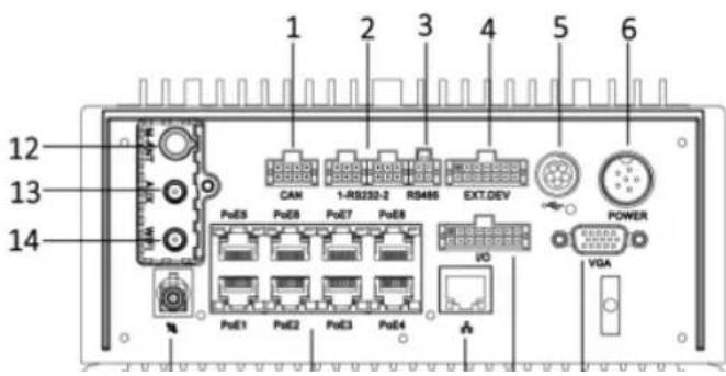
1.2 Rear Panel
text_image
1 2 3 4 5 6 12 13 14 PstE5 PstE8 PstE7 PstE8 PstE1 PstE2 PstE3 PstE4 CAN 1-RB232-2 RS486 EXT.DEV POWER VO VGAMobile Network Video Recorder User Manual
| 6 | Power | 6-pin aviation plug for power supply. |
| 7 | GNSS antenna | GNSS antenna interface. |
| 8 | PoE 1 to 8 | 8 × PoE interface. |
| 9 | Network interface | 1 × 10M/100M/1000M RJ45 Ethernet interface. |
| 10 | I/O | 4-ch alarm input, 2-ch alarm output, 4-ch sensor in, 1-ch pulse signal input. |
| 11 | VGA | VGA video output interface. |
| 12 | M-ANT | Main 3G/4G antenna interface. |
| 13 | AUX | Aux Wi-Fi antenna interface. |
| 14 | WIFI | Main Wi-Fi antenna interface. |
Chapter 2 Installation and Connections
2.1 Environment
To ensure the device can ventilate well, find a position with enough space. Recommended installation space is shown in Figure 2-1.

text_image
242.3 125.5 40 30 Unit: mm 30Figure 2-1 Recommended Installation Space
Mobile Network Video Recorder User Manual

Sunk Screws
Purpose:
Perform the following steps to install the HDD on the device. Figures in following steps are only for reference.
Step 1 Insert the key and turn counterclockwise to unlock dummy HDD.

natural_image
Technical diagram of an electronic device rear panel with ports and connectors (no text or labels)Figure 2-3 Unlock Dummy HDD
Step 2 Unfasten the two screws of dummy HDD and null dummy HDD out of device.
Mobile Network Video Recorder User Manual

text_image
Diagram showing assembly steps of an electronic device with labeled components and directional arrows indicating process flow.Figure 2-5 Take Apart Dummy HDD
Step 4 Place the first HDD into the dummy HDD, with the PCB facing down.

natural_image
Mechanical assembly diagram showing a component being lowered into a housing (no text or symbols visible)Mobile Network Video Recorder User Manual

natural_image
Technical line drawing of a mechanical assembly with screwdriver and housing (no text or symbols)Figure 2-8 Fix HDD
Step 7 Repeat step 4 to 6 to install the secondary HDD in the other socket of dummy HDD.

natural_image
Mechanical assembly diagram showing a lever mechanism with screwdriver and bracket (no text or symbols)Step 9 Plug the dummy HDD back to the device and then tighten the screws clockwise.
Step 10 Turn the key clockwise to lock dummy HDD.

natural_image
Technical line drawing of an electronic device showing internal components and a close-up view (no text or symbols)Figure 2-11 Finish Installation
2.3 Install SIM Card
Purpose:
Pluggable 3G/4G wireless communication module is designed for the device and you should install the SIM card to realize the wireless communication function.
Before You Start
Prepare the tools and components for installation:
SIM card
Wrench

Mobile Network Video Recorder User Manual
Step 2 Pull out the 3G/4G and Wi-Fi module.
Step 3 Press the yellow button on the 3G/4G slot and then pull the SIM card tray out.

text_image
SIM Card Tray Yellow ButtonSIM Card Slot
Figure 2-14 Pull out SIM Card Tray
Step 4 Place the SIM card on SIM card tray.

Mobile Network Video Recorder User Manual
natural_image
Diagram of an electronic circuit board layout with components and connections, no visible text or symbolsFigure 2-16 Insert SIM Card Tray back to SIM Card Slot
Step 6 Install the 3G/4G module back to the device and tighten the set screw.
2.4 Install SD Card
Before You Start
Prepare the tools and components for installation:
● Key to dummy HDD (delivered with device)
SD card

Mobile Network Video Recorder User Manual

text_image
Unfasten ScrewsFigure 2-19 Unfasten Screws
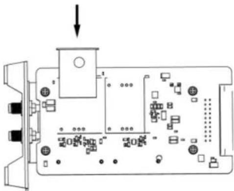
Step 3 Open the cover of SD card slot.

natural_image
Technical illustration of a heat exchanger or cooling unit with cooling fins and mounting ports (no text or symbols)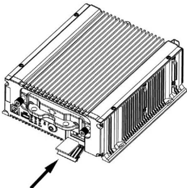
natural_image
Technical line drawing of an industrial heat exchanger unit with cooling fins and heat sinks (no text or symbols)Figure 2-21 Insert SD Card
Step 5 Plug the dummy HDD back to the device, close the cover of SD card slot, and then ghten the screws clockwise.
Step 6 Turn the key clockwise to lock dummy HDD.

natural_image
Technical line drawing of an electronic device showing internal structure before and after assembly (no text or symbols)Figure 2-22 Finish Installaon
2.5 Alarm Input/Output Connecon
2.5.1 Alarm Input Connecon
The device adopts the high/low-level electrical signals triggering (high level: 6 to 36 VDC; low level: 0 to 5 VDC) to realize alarm input. And in order to avoid error report caused by voltage actuaon, no alarm will be triggered by voltage ranging of 5 to 6 VDC.

text_image
Alarm Input IN(n) m DC (6~36V)Figure 2-23 Alarm Input Connecon
2.5.2 Alarm Output Connection
The alarm output interfaces A1 and B1 of the device is opened normally if no alarm occurs. When an alarm output is triggered, the corresponding A1 and B1 interfaces will be connected. Thus, the active alarm device is required for the system.

text_image
A1 B1 C1 D0Figure 2-24 Alarm Output Connection
2.6 Sensor-in Wiring
Step 1 Connect the delivered extension cable to I/O interface.
Step 2 Connect the vehicle braking, reversing, left-turn, and right-turn signals to sensor-in interface.
2.7 Power Cord Wiring
2.7.1 Shutdown Delay
Purpose:
The device starts up when the vehicle ignites and shuts down after the vehicle is off. The
Mobile Network Video Recorder User Manual

flowchart
graph TD
    A["Acc"] --> B["DC PN"]
    B --> C["Key of vehicle power"]
    C --> D["Vehicle ignition switch"]
    D --> E["positive pole ignition"]
    E --> F["Vehicle batteries"]
    F --> G["Positive pole"]
    G --> H["Negative pole"]
    H --> I["Vehicle power system"]
    I --> J["Connection of PoE Switch"]
    J --> K["Point of connection"]
Figure 2-25 Connection of Positive Pole Ignition Switch
i NOTE
- Please contact the vehicle manufacturer for the connection information of starting switch.
- The vehicle ignition switch, also called car key, controls the startup and shutdown of the vehicle. Most of vehicles adopt positive pole ignition switch currently.
- The normal vehicle power refers to the main power of the vehicle power supply system. After the vehicle is off, the normal vehicle power still provides direct-current source for the other devices inside and generally a main switch is used to turn on/off it.
2.7.2 Timed Shutdown
Step 1 Connect the "DC IN+" and "KEY+" of the device to the positive pole of vehicle
Mobile Network Video Recorder User Manual
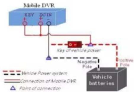
flowchart
graph TD
    A["Mobile DVR"] --> B["Key"]
    A --> C["DCIN"]
    B --> D["Vehicle Power system"]
    C --> E["Connection of Mobile DVR"]
    D --> F["Point of connection"]
    E --> G["Negative Pole"]
    F --> H["Positive Pole"]
    G --> I["Vehicle batteries"]
    H --> I
    style A fill:#4CAF50,stroke:#333
    style I fill:#2196F3,stroke:#333
Figure 2-26 Timing On/Off
Chapter 3 Start Up Device
3.1 Startup
Before you start:
● Install the HDD. Refer to 2.1 Environment for details.
- Connect the cables and modules correctly. Refer to Chapter 2 Installation and Connections for details.
Step 1 Insert the key into the dummy HDD lock.
Step 2 Rotate it clockwise to ON status.

NOTE
- Do not perform any operations during the startup process.
- The startup process takes about 1 minute. The system enters the live view interface after startup.
3.2 Activation
Purpose:
For the first-time access, you need to activate the device by setting an admin password. No operation is allowed before activation.
Step 1 Enter the same password in the text field of New Password and Confirm.

WARNING
STRONG PASSWORD RECOMMENDED—We highly recommend you create a strong password of your own choosing (Using a minimum of 8 characters, including at least three of the following categories: upper case leers, lower case leers, numbers, and special characters.) in order to increase the security of your product. And we recommend you reset your password regularly, especially in the high security system, reseng the password monthly or weekly can beer protect your product.
Step 2 Click OK to save the password and acvate the device.

For the old version device, if you upgrade it to the new version, a dialog box will pop up once the device starts up. You can click YES and follow the wizard to set a strong password.
Chapter 4 Network
4.1 Set Local Network
Step 1 Go to Menu > Basic Settings > Network.

text_image
Network Settings Ethernet Port IP Address Subnet Mask Default Gateway Preferred DNS Server Alternate DNS Server MAC Address Static IP Address More Settings Network Interface 1 10 12 5 204 255 .255 .255 .0 10 12 5 254 00:40:3b:9d:96:9b 192.168.1.65 Set Apply OK CancelFigure 4-1 Local Network Settings
Step 2 Select Ethernet Port to configure.
● Network Interface 1: The network interface in front panel.
● Network Interface 2: The network interface in rear panel.
Step 3 Enter the device IP Address, Subnet Mask, Default Gateway, DNS Server Address, and Download Server IP.
Step 4 Optionally, click Set of More Settings to enable/disable LAN Sharing.
Mobile Network Video Recorder User Manual

text_image
Dial Settings Select Module Module(WCDMA) Enable Dialing Network Mode Auto More Settings Set OK CancelFigure 4-2 Dialing Settings
Step 2 Check Enable Dialing.
Step 3 Configure the 3G/4G VPDN (Virtual Private Dialup Network) settings. Please consult the local operator for the network parameters of the VPDN.
1) Click Set of More Settings.
2) Select Bearing Mode.
3) Enter APN (Access Point Name), Dial Number, User Name, and Password.
4) Select Verification Protocol.
5) Click OK.
Step 4 Click OK and reboot the device to activate the new settings.
Step 5 Optionally, go to Menu > Status > Dial to view dialing status.
4.2.2 Set Wi-Fi
Purpose:
Step 3 Select the Configuration file. 5 configuration files are available and only one SSID can be set for each file.
Step 4 Select network SSID (Service Set Identifier), Security Type, Encryption Type, and Key.
Step 5 Set the IP address and DNS server for Wi-Fi network.
1) Click Set of More Settings.
2) Configure IP address and DNS parameters.
3) Click OK.

text_image
WIFI Settings DHCP IP Address Subnet Mask Default Gateway Auto-Obtain DNS Preferred DNS Server Alternate DNS ServerFigure 4-4 IP & DNS Settings for Wi-Fi
Step 6 Click OK.
Step 7 Optionally, go to Menu > Status > WiFi to view the Wi-Fi status.

text_image
WiFi Status Enable Disable Status Unknown SSID UnknownMobile Network Video Recorder User Manual
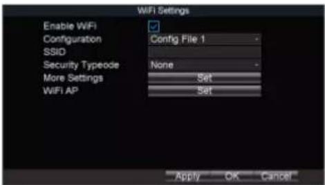
text_image
WiFi Settings Enable WiFi Configuration SSID Security Typeode More Settings WiFi AP Config File 1 None Set Set Apply OK CancelFigure 4-6 Wi-Fi Settings
Step 2 Click Set of WiFi AP

text_image
WiFi Access Point Enable WiFi AP Enable WiFi Broadcast Enable WiFi Hotspot SSID Encryption Type More Mobile AP No Settings Apply OK CancelFigure 4-7 Wi-Fi Access Point Settings
Step 3 Check Enable WiFi AP and edit other parameters as required.
Enkla WIEI AB: Once enabled, the devices can work as a misalignment route.
Mobile Network Video Recorder User Manual
- The IP address of the platform server to add the device is set as the trusted IP address.
- Up to 16 IP addresses can be added on the authorized list.
Step 1 Go to Menu > Other Settings > Firewall.
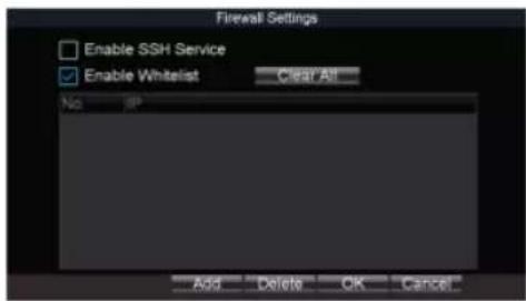
text_image
Firewall Settings Enable SSH Service Enable Whitelist Clear All No Add Delete OK CancelFigure 4-8 Firewall Settings
Step 2 Optionally, select Enable SSH Service to effectively prevent information leakage during remote management.
Step 3 Click Add.
Step 4 Enter the trusted IP address and click OK.

text_image
Add IP Address OK CancelFigure A-9 Add ID Address
Chapter 5 IP Camera Management
Purpose:
Add IP cameras to the device. You can get the live view, record the video, and set the parameters of the connected IP camera. If the device provides PoE function, you can connect the PoE cameras to the device PoE interfaces.
5.1 Activate IP Camera
Purpose:
Before adding an IP camera, activate it by setting a password for it.
5.1.1 Auto Activation
Purpose:
Activate the IP camera by setting its password the same with the device password.
Step 1 Go to Menu > Other Settings > IPC Settings.
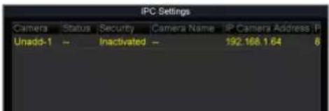
text_image
IPC Settings Camera Status Security Camera Name IP Camera Address IP Unadd-1 -- Inactivated -- 192.168.1.64 8Mobile Network Video Recorder User Manual

text_image
IPC Settings Camera Status Security Camera Name IP Camera Address P Unadd-1 - Inactivated - 192 108.1.64 8 Refresh Quickly Add Manual Add Edit Quickly Activate Manual Activate ExitFigure 5-2 IPC Settings
Step 2 Select an inactivated IP camera.
Step 3 Click Manually Activate.
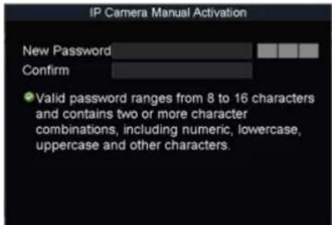
text_image
IP Camera Manual Activation New Password Confirm • Valid password ranges from 8 to 16 characters and contains two or more character combinations, including numeric, lowercase, uppercase and other characters.5.2 Add IP Camera
Purpose:
You can add the online IP cameras. Ensure the network communicaon between the device and IP camera is well.
5.2.1 Quick Add
Purpose:
The online IP cameras in the same network segment with the device will be displayed on a list. If the IP camera on the list has the same password with the device, you can quickly add it.
Before you start:
Make sure the IP camera password is the same with the device.
Step 1 Go to Menu > Other Sengs > IPC Sengs.
Step 2 Select an online IP camera.
Step 3 Click Quickly Add.
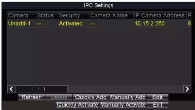
text_image
IPC Settings Camera Status Security Camera Name IP Camera Address P Unadd-1 -- Activated -- 10.15.2 250 8 Refresh Delete Quickly Add Manually Add Edit Quickly Activate Manually Activate ExitFigure 5-4 Quick Add
● : The IP camera is disconnected.
● : The IP camera is connected.
5.2.2 Manual Add
Step 1 Go to Menu > Other Sengs > IPC Sengs.
Step 2 Click Manually Add.
Step 3 Select the IP channel No. for the IP camera.
Step 4 Edit the required informaon, including the IP Address, Protocol, Port No., User Name, and Password.
Step 5 Click OK.
Mobile Network Video Recorder User Manual

text_image
Add IP Camera Manually Channel No. D1 - IP Address 10 15 2 250 Manufacturer HIKVISION - Management Port 8000 User Name admin Password Protocol OK CancelFigure 5-5 Manual Add
5.2.3 Edit Protocol
Purpose:
To connect the network cameras which are not configured with the standard protocols, you can configure the customized protocols for them. The system provides 16 customized protocols.
Step 1 Go to Menu > Other Settings > IPC Settings.
Step 2 Click Manually Add.
Step 3 Click Protocol.
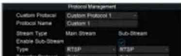
text_image
Protocol Management Custom Protocol Custom Protocol 1 Protocol Name Custom 1 Stream Type Main Stream Sub-Stream Enable Sub-Stream Type RTSP RTSP Transfer Protocol SubMobile Network Video Recorder User Manual

text_image
Edit Added IP Camera Channel No D1 IP Address 80 15 2 250 Manufacturer Management Port 8000 User Name admin Password **** OK CancelFigure 5-7 Edit IP Camera
5.4 Delete IP Camera
Step 1 Select an IP camera and click Delete.
Step 2 Click Yes on the pop-up dialog box.
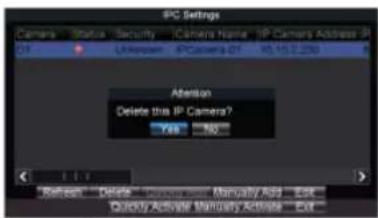
text_image
IPC Settings Camera Status Security ICamera Name IP Camera Address IP 01 TI Unknown IPCamera 01 10.15.2.230 Attention Delete this IP Camera? Yes No Refresh Delete Advisors Monally Add... Edit... Quick Active Maternity Active... Edit...Figure 5-8 Delete IP Camera
Chapter 6 Camera Management
6.1 Basic Image Settings
6.1.1 Set OSD Parameters
Purpose:
Configure the camera name, OSD (On Screen Display) settings, etc.
Step 1 Go to Menu > Other Settings > Camera.

text_image
Camera Settings Camera IP Camera 1 Camera Name IPCamera 01 Display Type Camera Name Date Week Date Format MM-DD-YYYY Time Format 24-Hour OSD Property Non-Transparent & Not - OSD Position OSD Position More Setting Set Copy to All Copy OK CancelFigure 6-1 Camera Settings
Step 2 Select Camera to configure.
Step 2 Edit parameters as your design
Mobile Network Video Recorder User Manual

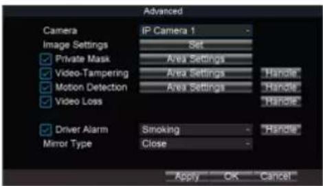
text_image
Advanced Camera IP Camera 1 Image Settings Set Private Mask Area Settings Video-Tampering Area Settings Handle Motion Detection Area Settings Handle Video Loss Handle Driver Alarm Smoking Handle Mirror Type Close Apply OK CancelFigure 6-2 More Setting
Step 3 Click Set of Image Settings.

text_image
Brightness Contrast Saturation Hue Default OK CancelFigure 6-3 Image Settings
Step 4 Edit the parameters.
Step 5 Click OK.
Step 6 Click OK in advanced settings interface.
Step 7 Click OK in camera settings interface.
6.2 Set Privacy Mask
Mobile Network Video Recorder User Manual
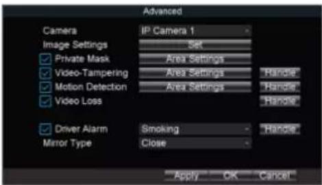
text_image
Advanced Camera IP Camera 1 Image Settings Set Private Mask Area Settings Video-Tampering Area Settings Handle Motion Detection Area Settings Handle Video Loss Handle Driver Alarm Smoking Handle Mirror Type Close Apply OK CancelFigure 6-4 Advanced Settings
Step 2 Click Set of More Setting.
Step 3 Check Private Mask.
Step 4 Click Area Settings of Private Mask.
Step 5 Draw areas.
Step 6 Right click and select Exit.
Step 7 Click OK in Advanced settings interface.
Step 8 Click OK in Camera settings interface.
6.3 Set Mirror Type
Purpose:
Set the mirror type of the image as left/right, up/down, or center. The camera image will
Step 3 Select Mirror Type as required.
Step 4 Click OK in Advanced sengs interface.
Step 5 Click OK in Camera sengs interface.
Chapter 7 Live View
7.1 Preview Settings
Purpose:
Configure the dwell time of live view, set the camera order, enable/disable the audio preview, etc.
Step 1 Go to Menu > Other Settings > Preview.

text_image
Preview Settings Video Output VGA Preview Mode 4 * 4 Dwell Time No Switch Camera Order Set Enable Audio Output OK CancelFigure 7-1 Preview Settings
Step 2 Select the Video Output according to the actual needs.
Step 3 Configure the Preview Mode, Dwell Time, and Enable Audio Output.
● Preview Mode: Select the window division mode for live view.
Mobile Network Video Recorder User Manual

text_image
Preview Settings Video Output VGA Preview Mode 4 * 4 Dwell Time No Switch Camera Order Set Enable Audio Output OK CancelFigure 7-2 Preview Settings
Step 2 Configure Preview Mode. We take the example of preview mode is 1+1 to describe the following steps.
Step 3 Click Set of Camera Order.
Step 4 Click // of window-1 to select camera to display.
Step 5 Click /> of window-2 to select camera to display.
Step 6 Click ▶ to switch to next page.
Step 7 Repeat step 4 to 6 to configure camera order for other pages.
Step 8 Click OK.
7.3 Right-Click Menu
Purpose:
In live view, right click to pop up right-click menu.
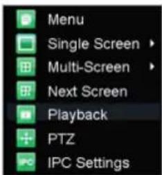
text_image
Menu Single Screen > Multi-Screen > Next Screen Playback PTZ IPC SettingsFigure 7-4 Right-Click Menu
Table 7-1 Item Description
| Item | Description |
| Menu | Enter the main menu of the system by right clicking the mouse. |
| Multi-Screen | Adjust the screen layout by choosing from the dropdown list. |
| Next Screen | Switch to the next screen. |
| Playback | Enter the playback interface and start playing back the video of the selected channel immediately. |
| PTZ | Click to pop up PTZ control panel. |
Mobile Network Video Recorder User Manual

text_image
PTZ Settings Camera IP Camera 1 Baudrate 9000 Data Bit 8 Stop Bit 1 Parity None Flow Ctrl None PTZ Protocol PELCO-D Address 1 Copy to All Copy OK CancelFigure 7-5 PTZ Settings
Step 2 Select the Camera for PTZ settings.
Step 3 Configure the parameters of the PTZ camera.

NOTE
All the parameters should be exactly the same with those of the PTZ camera.
Step 4 Click OK.
7.4.2 PTZ Control Panel
In live view interface, right click a PTZ camera and click PTZ on right-click menu.

text_image
Zoom Focus Iris Preset PatrolChapter 8 Storage
8.1 Storage Sengs
8.1.1 Format HDD
Purpose:
A newly installed hard disk drive (HDD) must be initialized before it can be used.
Step 1 Go to Menu > Storage.
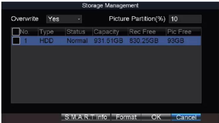
text_image
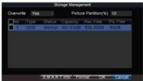
Storage Management Overwrite Yes Picture Partition(%) 10 No. Type Status Capacity Rec Free Pic Free 1 HDD Normal 931.51GB 830.25GB 93GB S.M.A.R.T Info Format OK CancelFigure 8-1 Storage Management
Step 2 Check the HDD to format.
Step 3 Click Format.
8.1.2 Congure Overwrite
Purpose:
The overwrite funcon is enabled by default. If the funcon is disabled, the recording and capturing will be stopped when the storage device is full.
Step 1 Go to Menu > Storage.
Mobile Network Video Recorder User Manual
text_image
Storage Management Overwrite Yes Picture Partition(%) 10 No. Type Status Capacity Rec Free Pic Free 1 HOC Normal 931.51GB 830.25GB 90GB SMART Info Format OK CancelFigure 8-2 Storage Management
Step 2 Select Overwrite as Yes or No.
Step 3 Click OK.
8.1.3 Configure Picture Partition
Purpose:
Specify the percentage of picture partition among the whole storage capacity. You can start capturing in eHome platform.
Step 1 Go to Menu > Storage.
text_image
Storage Management Overwrite Yes Picture Partition(%) 10 No Type Status Capacity Rec Free Pic Free 1 HDD Normal 231.51GB 830.25GB 95GBMobile Network Video Recorder User Manual
The S.M.A.R.T. (Self-Monitoring, Analysis and Reporting Technology) is a monitoring system for HDD to detect and report on various indicators of reliability in the hopes of anticipating failures.
Step 1 Go to Menu > Storage.
text_image
Storage Management Overwrite Yes Picture Partition(%) 10 No Type Status Capacity Rec Free Pic Free 1 HDD Normal 801.51GB 830.25GB 91GB SMART Info Format OK CancelFigure 8-4 Storage Management
Step 2 Select an HDD.
Step 3 Click S.M.A.R.T. Info.

text_image
S.M.A.R.T Info Hard Disk Hard Disk2 S.M.A.R.T Info ID Property Flags TI 0x1 Raw Read Error Rate 24 5 0x4 Start/Stop Count 32 0 0x5 Reallocated Sector Count 33 14 0x7 Seek Error Rate 2e 0 0x9 Power-on Hours Count 32 0 0x10 Up-Up Retay Count 32 0Mobile Network Video Recorder User Manual

text_image
Record Settings Camera IP Camera 1 Encoding Parameters Main Stream(Normal) Stream Type Video Resolution 1920*1080(1080P) Bitrate Type Variable Video Quality Medium Frame Rate 6fps Max. Bitrate(Kbps) 1024 Schedule Set More Settings Set Copy to All Copy Add(Y) OK CancelFigure 8-6 Record Settings
Step 2 Select Camera.
Step 3 Configure the image parameters.
- Encoding Parameters
● Main Stream (Normal): Used for continuous recording.
● Main Stream (Event): Used for event recording.
- Sub-Stream: Used for network transmission.
Stream Type
Video and Video & Audio are selectable.
- Bitrate Type
● Variable and Constant are selectable.
● Variable: The video quality is configurable.
- Constant: The video quality is set as Medium and cannot be edited.
-
-
- 4.
-
Mobile Network Video Recorder User Manual
- Post-Record: After the event finished, the video can also be recorded for a certain time. For example, when an alarm ends at 11:00, if the post-record time is set as 5 seconds, the camera records till 11:00:05.
Step 6 Click OK.
8.2.2 Configure Motion Detection Recording
Purpose:
In the motion detection recording, once a motion event occurs, the device starts to record.
Step 1 Go to Menu > Other Settings > Camera.
Step 2 Click Set of More Setting.

text_image
Advanced Camera Image Settings ✓ Private Mask ✓ Video-Tampering ✓ Motion Detection ✓ Video Loss ✓ Video Quality ✓ Driver Alarm Mirror Type Analog 1 Set Area Settings Area Settings Area Settings Handle Handle Handle Smoke Close Apply OK CancelFigure 8-7 Motion Detection Settings
Step 3 Check Motion Detection.
Step 4 Click Area Settings of Motion Detection.
Mobile Network Video Recorder User Manual
Step 1 Go to Menu > Other Settings > Alarm In.

text_image
Alarm Input Settings Alarm Input No. Ac-1 Alarm Name Trigger Level High Level Triggered Camera Set Schedule Set Linkage Action Copy to All Copy Apply OK CancelFigure 8-8 Alarm Input Settings
Step 2 Click Set of Triggered Camera to select the alarm triggered recording channel.
Step 3 Click OK.
Step 4 Enter the record settings interface to set alarm triggered recording schedule. Refer to 8.2.5 Configure Schedule for record settings. Recording type must be alarm, motion | alarm, or motion & alarm.
8.2.4 Configure Alarm Terminal
Before you start:
● Install an alarm terminal. For details, refer to alarm terminal user manual.
- The RS-232 serial port should be used in the way of transparent channel and the baud rate should be set as 9600.
Step 4 Select Set of Triggered Camera to set the alarm triggered recording channel.
Step 5 Click OK.
8.2.5 Configure Schedule
Step 1 Go to Menu > Basic Settings > Record.
Step 2 Click Set of Schedule.
Step 3 Check Enable Schedule.
Step 4 Select the day from the dropdown list for settings.
Step 5 Configure all day schedule or custom schedule.
- Check All Day to enable all-day recording, and then select the recording type from the drop-down list.
- Uncheck All Day, customize the time period for recording, and select the recording type for each time period.
Step 6 Click OK.

NOTE
- 5 recording types are selectable: Normal, Motion Detection, Alarm, Motion|Alarm, and Motion&Alarm.
- Up to 8 time periods can be set for each day and each of the time periods cannot be overlapped.

Mobile Network Video Recorder User Manual

text_image
Sensor-In Settings Seq Sensor-In Behavior Triggering Level Full Screen Monitoring S1 Brake High Level No Triggering S2 Left Turn High Level No Triggering S3 Right Turn High Level No Triggering S4 Reverse High Level No Triggering OK CancelFigure 8-11 Sensor-In Settings
Step 2 Set Triggering Level and Full Screen Monitoring for sensor-in. Step 3 Click OK.
Chapter 9 Playback
9.1 Instant Playback
Purpose:
You can search and play back the record files stored on the device instantly.
Step 1 Go to Menu > Video Search.

text_image
Video Search Search Mode General Camera IP Camera 1 Video Type All Start Time < 2017 > < 11 > < 21 > < 0 > < 0 > < 0 > End Time < 2017 > < 11 > < 21 > < 23 > < 59 > < 59 > Play Search CancelFigure 9-1 Video Search
Step 2 Select Search Mode as General. Only the general video supports instant playback.
General: Normal videos.
Step 3 Select Camera.
Mobile Network Video Recorder User Manual
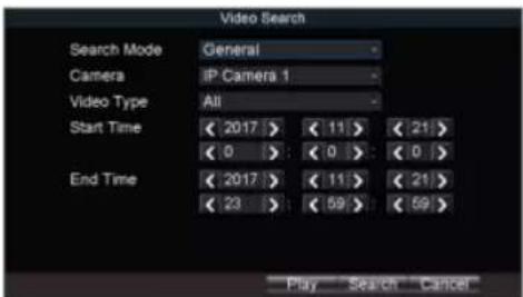
text_image
Video Search Search Mode General Camera IP Camera 1 Video Type All Start Time < 2017 > < 11 > < 21> < 0 > < 0 > < 0 > End Time < 2017 > < 11 > < 21> < 23 > < 59 > < 59 > Play Search CancelFigure 9-2 Video Search
Step 2 Select Search Mode.
● General: Normal videos.
Event: Motion detection, alarm, motion|alarm, and motion&alarm videos.
Step 3 Select Camera.
Step 4 Select Video Type.
Step 5 Specify Start Time and End Time.
Step 6 Click Search. The matched videos will be displayed.

text_image
Search Results Channel Start Time End Time Size D1 11-22-2017 10:15:23 10:36:14 33,434 KB D1 11-22-2017 10:38:24 10:39:31 1,788 KB D1 11-22-2017 10:39:41 11:14:18 107,438 KB D1 11-22-2017 11:14:31 11:17:03 8,997 KBChapter 10 Platform
10.1 eHome
Purpose:
The device can be remotely accessed via eHome platform.
Before you start:
Create the device ID on the eHome platform.
Step 1 Go to Menu > Basic Settings > Platform.
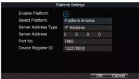
text_image
Platform Settings Enable Platform Select Platform Platform eHome Server Address Type IP Address Server Address 0 0 0 0 Port No. 7660 Device Register ID 122578038 OK CancelFigure 10-1 Platform Settings
Step 2 Check Platform Enable.
Before you start:
Register the device in guarding vision platform. For detailed steps, refer to 10.3 Register Device in Guarding Vision platform.
Step 1 Go to Menu > Basic Settings > Platform.

text_image
Platform Settings Enable Platform Select Platform Guarding Vision OK CancelFigure 10-2 Platform Settings
Step 2 Check Enable Platform.
Step 3 Select Platform as Guarding Vision.
Step 4 Click OK and reboot the device to activate the new settings.
Step 5 Optionally, go to Menu > Status > Platform to view the platform status.
10.3 Register Device in Guarding Vision platform
Step 1 Access Guarding Vision platform.
Chapter 11 Backup
11.1 Manual Backup
Purpose:
Back up the videos stored on the device.
Step 1 Go to Menu > Video Search.

text_image
Video Search Search Mode General Camera IP Camera 1 Video Type All Start Time < 2017 > < 11 > < 21 > < 0 > < 0 > < 0 > End Time < 2017 > < 11 > < 21 > < 23 > < 59 > < 59 > Play Search CancelFigure 11-1 Video Search
Step 2 Select Search Mode.
● General: Normal videos.
Event: Motion detection, alarm, motion | alarm, motion&alarm videos.
Step 2 Select Camera
Step 7 Select the videos and click Export.
11.2 Format Backup Device
Purpose:
View the status and the free space/capacity of the connected backup device. And you can also format the backup device.
Step 1 Go to Menu > Maintenance > Storage.

text_image
Backup Medium Backup Device USB Status Normal Free Space/Capacity 14.40GB / 14.43GB Format OK CancelFigure 11-3 Backup Device
Step 2 Select Backup Device.
Step 3 View the Status and Free Space/Capacity of the backup device.
Step 4 Click Format to format the selected backup device.
Chapter 12 Events and Alarms
12.1 Configure Motion Detection Alarm
Purpose:
When motion detection alarm is configured, once a motion event is detected, the device starts to record and multiple linkage actions will be triggered.
Step 1 Go to Menu > Other Settings > Camera.
Step 2 Click Set of More Setting.
text_image
Advanced Camera Image Settings ✓ Private Mask ✓ Video-Tampering ✓ Motion Detection ✓ Video Loss Driver Alarm Mirror Type IP Camera 1 Set Area Settings Area Settings Area Settings Handle: Handle: Handle: Smoking Close Apply OK CancelFigure 12-1 Motion Detection Settings
Step 3 Check Motion Detection.
Mobile Network Video Recorder User Manual
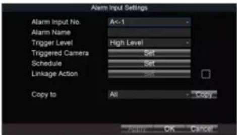
text_image
Alarm Input Settings Alarm Input No. A<-1 Alarm Name Trigger Level High Level Triggered Camera Set Schedule Set Linkage Action Copy to All Copy Apply OK CancelFigure 12-2 Alarm Input Settings
Step 2 Select Alarm Input No.
Step 3 Enter Alarm Name.
Step 4 Select Trigger Level.
● High level: 6 to 36 VDC.
● Low level: 0 to 5 VDC.

In order to avoid error caused by voltage fluctuation, no alarm will be triggered by voltage ranging from 5 VDC to 6 VDC.
Step 5 Click Set of Schedule to set arming schedule. For detailed steps, refer to 12.10 Configure Arming Schedule and Linkage Actions.
Step 6 Check Linkage Action and click Set of Linkage Action to set the linkage actions. For detailed steps, refers to 12.10 Confuse Action Schedule and Linkage Actions
Mobile Network Video Recorder User Manual

text_image
Alarm Output Settings Alarm Output No. A->1 Alarm Name Dwell Time 6s Arming Schedule Set Copy to All Copy OK CancelFigure 12-3 Alarm Output Settings
Step 2 Select Alarm Output No.
Step 3 Enter Alarm Name.
Step 4 Select Dwell Time.
● Dwell Time: Alarm output will keep alarming for the dwell time.
Step 5 Click Set of Schedule to set the arming schedule for alarm outputs. For detailed steps, refer to 12.10 Configure Arming Schedule and Linkage Actions.
Step 6 Click OK.
12.4 Configure Alarm Terminal
Step 1 Go to Menu > Other Settings > Alarm Terminal.

12.5 Congure Video Loss Alarm
Purpose:
When the device cannot receive video signal from the front-end devices, the video loss alarm will be triggered. Linkage acons, including audible warning and alarm output, can be set to respond.
Step 1 Go to Menu > Other Sengs > Camera.
Step 2 Click Set of More Seng.

text_image
Advanced Camera IP Camera 1 Image Settings Set ✓ Private Mask Area Settings ✓ Video-Tampering Area Settings ✓ Motion Detection Area Settings ✓ Video Loss Handle Handle Handle ✓ Driver Alarm Smoking ✓ Handle Mirror Type Close Apply OK CancelFigure 12-5 Video Loss
Step 3 Check Video Loss.
Step 4 Set arming schedule and linkage acons. For detailed steps, refer to 12.10 Congure Arming Schedule and Linkage Acons.
Step 5 Click OK.
12.6 Congure Video Tampering Alarm
Purpose:
A tampering alarm is triggered when the camera is covered and the monitoring area cannot be viewed. Linkage acons, including audible warning, alarm output, can be set to respond.
Step 1 Go to Menu > Other Sengs > Camera.
Step 2 Click Set of More Seng.
Mobile Network Video Recorder User Manual

text_image
Advanced Camera IP Camera 1 Image Settings Set Private Mask Area Settings Video-Tampering Area Settings Handle Motion Detection Area Settings Handle Video Loss Handle Driver Alarm Smoking Handle Mirror Type Close Apply OK CancelFigure 12-6 Video-Tampering
Step 3 Check Tamper-proof.
Step 4 Set area for video tampering detection. For detailed steps, refer to 12.11 Configure Detection Area.

NOTE
The video tampering alarm can be triggered only when the view of the camera is fully covered.
Step 5 Set arming schedule and linkage actions. For detailed steps, refer to 12.10 Configure Arming Schedule and Linkage Actions.
Step 6 Click OK.
12.7 Configure Exception Alarm
Step 2 Select Exception Type and set corresponding alarm linkage actions, including audible warning and alarm output.
Step 3 Click OK.
Exception types include:
- HDD Full: The HDD is full.
- HDD Error: Writing HDD error, unformatted HDD, etc.
● Network Disconnected: Network cable is disconnected.
● IP Conflicted: Duplicated IP address. - Illegal Login: Incorrect user ID or password.
- Video Input/Output Standard Mismatched: Input and output video standards do not match.
● Abnormal Recording: No space for saving recorded files.
12.8 Configure Satellite Positioning
Purpose:
The built-in GNSS module supports GPS (Global Positioning System), enabling device positioning and speed limit alarm.
Step 1 Go to Menu > Basic Settings > Position.

text_image
Positioning Settings Positioning Module Built-in Satellite Time Adjusting □ Time Zone (GMT+08.00) Beijing, U Speed Unit km/h Speed Limit 100Step 6 Click Set of Display Channel and select display channels. The device positioning information will be displayed on the selected channels.
Step 7 Click OK.
Step 8 Optionally, go to Menu > Status > Position to view positioning status.
12.9 Configure G-Sensor Alarm
Purpose:
G-Sensor detects and records acceleration information in 3-axial (X, Y, Z) directions.
Before you start:
Connect an external sensor to the device for obtaining and providing the acceleration speed in 3-axial directions.
Step 1 Go to Menu > Basic Settings > G-Sensor.
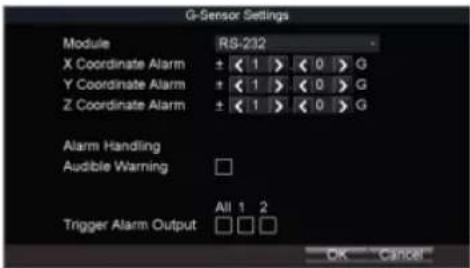
text_image
G-Sensor Settings Module RS-232 X Coordinate Alarm ± < 1 > < 0 > G Y Coordinate Alarm ± < 1 > < 0 > G Z Coordinate Alarm ± < 1 > < 0 > G Alarm Handling Audible Warning Trigger Alarm Output All 1 2 OK CancelFigure 12-9 G-Sensor Settings
12.10 Configure Arming Schedule and Linkage Actions
Step 1 Click Handle to set the arming schedule and alarm linkage actions.
Step 2 Select the day from Arming Schedule dropdown list.
Step 3 Set the arming period for selected day.
Step 4 (Optional) Copy the current settings to other days in the week.
Step 5 Check to enable linkage actions.
● Full Screen Monitoring
When an alarm is triggered, the local monitor displays the video image from the alarming channel configured for full screen monitoring.
Audible Warning
Trigger an audible beep when an alarm is detected.
- Trigger Alarm Output
Trigger an alarm output when an alarm is detected.
Step 6 Click OK.
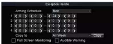
text_image
Exception Handle Arming Schedule Mon 1 < 0 > < 0 > - < 24 > < 0 > 2 < 0 > < 0 > - < 0 > < 0 > 3 < 0 > < 0 > - < 0 > < 0 > 4 < 0 > < 0 > - < 0 > < 0 > Copy to All Week Copy Full Screen Monitoring Audible WarningChapter 13 User Account Management
13.1 Add User
Purpose:
Add and delete users, and modify the password and permission of users.
Step 1 Go to Menu > Other Settings > User.

text_image
User Settings No User Name Level 1 admin Administrator Add Delete ModifyFigure 13-1 User Management
Step 2 Click Add.

text_image
Add User Name PasswordMobile Network Video Recorder User Manual
13.2 Delete User
Step 1 Go to Menu > Other Settings > User.
Step 2 Select a user and click Delete.
Step 3 Click Yes in confirmation message box.
13.3 Edit User
Step 1 Go to Menu > Other Settings > User.
Step 2 Select a user and click Modify.
Step 3 Edit parameters as required.
Step 4 Click OK.
Chapter 14 General System Configuration
14.1 Configure Basic Display Settings
Purpose:
Set system time, select CVBS output standard, enable password and configure DST settings, etc.
Step 1 Go to Menu > Other Settings > Display.
NOTE
The system language is set as English by default and is not editable.
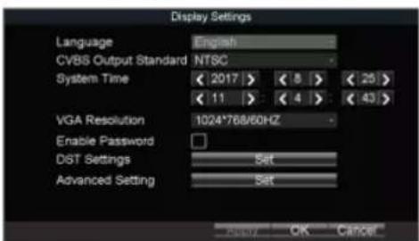
text_image
Display Settings Language English CVBS Output Standard NTSC System Time < 2017 > < 8 > < 25 > < 11 > < 4 > < 43 > VGA Resolution 1024*768/60HZ Enable Password DIST Settings Set Advanced Setting Set Reply OK CancelFigure 14-1 Display Settings
Mobile Network Video Recorder User Manual
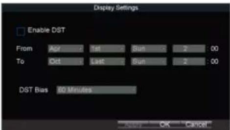
text_image
Display Settings Enable DST From Apr 1st Sun 2:00 To Oct Last Sun 2:00 DST Bias 80 Minutes OK CancelFigure 14-2 DST Settings
Step 3 Check Enable DST.
Step 4 Set the start time and end time for DST.
Step 5 Select DST bias.
Step 6 Click OK in DST settings interface.
Step 7 Click OK in Display Settings.
14.3 Configure NTP
Step 1 Go to Menu > Basic Settings > Network.
Step 2 Click Set of More Settings.
Step 3 Click Set of NTP.

Step 8 Click OK in network sengs interface.
14.4 Congure Advanced Display Sengs
Purpose:
Set the system me, select the CVBS output standard, enable the password, conjure the DST sengs, etc.
Step 1 Go to Menu > Other Sengs > Display.
Step 2 Click Set of Advanced Sengs.
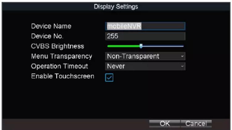
text_image
Display Settings Device Name mobileNVR Device No. 255 CVBS Brightness Menu Transparency Non-Transparent Operation Timeout Never Enable Touchscreen ✓ OK CancelFigure 14-4 Advanced Sengs
Step 3 Edit parameters as required.
● Device Name: Enter the system name as desired.
● Device No.: Edit the device No. for remote control. The device No. ranges from 1 to 255. The default device No. is 255. It is not recommended to modify Device No. Otherwise, you need to enter the Device No. on the remote control every me you use it.
● CVBS Brightness: Adjust video output brightness.
- Menu Transparency: The transparency proporon of the menu displayed on the live view interface. You can set it as 1:3, 1:1, 3:1, or Non-transparent. The smaller the proporon value is, the more transparent the menu is. When Non-transparent is selected, only the menu is displayed on the page.
- Operaon Timeout: If no operaon is performed aer a specied period of me, live view will be displayed automacally.
- Enable Touchscreen: Enable/disable touchscreen. If the funcon is on, PTZ funcon is unavailable.
Step 4 Click OK.
Chapter 15 Maintenance
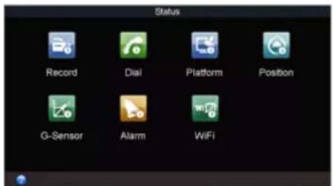
15.1 Check Status
Go to Menu >Status to view status of recording, 3G/4G, platform, satellite positioning, G-Sensor, alarm, and WiFi.
text_image
Status Record Dial Platform Position G-Sensor Alarm WiFiFigure 15-1 Status
15.2 View System Information
Go to Menu > Maintenance > Information to view the device name, model, serial No., firmware version, encoding version, and panel version.

15.3.1 Upgrade by Local USB Flash Disk
Before you start:
- Connect the USB device that contains the upgrade firmware.
● The upgrade firmware should be stored in the root directory of the USB device.
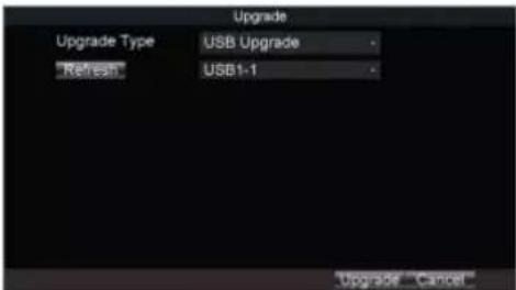
Step 1 Go to Menu > Maintenance > Upgrade.
Step 2 Select Upgrade Type as USB Upgrade.
text_image
Upgrade Upgrade Type USB Upgrade "Refresh" USB1-1 Upgrade CancelFigure 15-3 Upgrade
Step 3 Click Upgrade to start upgrading and reboot the device to activate the new settings.
15.3.2 Upgrade by Remote FTP server
Before you start:
Ensure the network connection of the PC (running FTP server) and the device is valid and correct. Run the FTP server on the PC and copy the firmware into the corresponding
Mobile Network Video Recorder User Manual
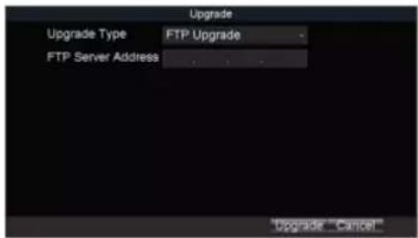
text_image
Upgrade Upgrade Type FTP Upgrade FTP Server Address Upgrade CancelFigure 15-4 Upgrade
Step 2 Select Upgrade Type as FTP Upgrade.
Step 3 Enter FTP Server Address.
Step 4 Click Upgrade to start upgrading and reboot the device to activate the new settings.
15.4 Log Operation
15.4.1 Search Log File
Purpose:
The operation, alarm, exception and information of the device can be stored in log files, which can be viewed and exported at any time.
Step 1 Go to Menu > Maintenance > Log Search.

15.4.2 Export Log File
Purpose:
The operation, alarm, exception and information of the device can be stored in log files, which can be viewed and exported at any time.
Before you start:
Connect a backup device to the device.
Step 1 Go to Menu > Maintenance > Log Search.

text_image
Log Search Major Type All Minor Type All Start Time < 2017 > < 8 > < 25 > < 0 > < 0 > < 0 > End Time < 2017 > < 8 > < 25 > < 23 > < 59 > < 59 > Search CancelFigure 15-6 Log Search
Step 2 Search log files. For detailed steps, refer to 15.4.1 Search Log File.
Step 3 Click Export.
15.5 Restore Default Settings
- Default: Restore all parameters, except the network (including IP address, subnet mask, gateway, MTU, NIC working mode, default route, server port, etc.) and user account parameters, to the factory default settings.
● Factory: Restore all parameters to the factory default settings.
Step 3 Click OK.
Step 4 Click Yes in confirmation message box.
15.6 Import/Export Configuration File
15.6.1 Import Configuration File
Purpose:
The configuration files of one device can be imported to multiple device devices if they are to be configured with the same parameters.
Before you start:
Connect a backup device that contains the configuration file to the device. The configuration file should be stored on the root directory of the backup device.
Step 1 Go to Menu > Maintenance > Configuration.

text_image
Import/Export Configuration File "Refresh" USB1-1 Free Space 14.26GBMobile Network Video Recorder User Manual
Step 1 Go to Menu > Maintenance > Configuration.

text_image
Import/Export Configuration File Refresh USB1-1 Free Space 14.26GB Import Export CancelFigure 15-9 Import/Export Configuration Files
Step 2 Click Export.
15.7 Serial Port Settings
Purpose:
Two types of serial ports are provided: RS-232 and RS-485.
The RS-232 port can be used in two ways:
- Parameters Configuration: Connect a PC to the device through the PC serial port. Device parameters can be configured by using software such as HyperTerminal. The serial port parameters must be the same as of the device when connecting with the PC serial port.
- Transparent Channel: Connect a serial device directly to the device. The serial device will be controlled remotely by the PC through the network and the protocol of the serial
Mobile Network Video Recorder User Manual
Step 3 Click OK.
Chapter 16 Shut Down Device
16.1 Enable Scheduled Startup/Shutdown
Purpose:
Set the scheduled startup/shutdown. The device will automatically start up/shut down according to the schedule.
Step 1 Go to Menu > Basic Settings > Start.
Step 2 Select Startup/Shutdown Mode as Scheduled Startup/Shutdown.

text_image
Start Control Startup/Shutdown Mode Scheduled Startup/Shu - Date Monday Time Segment 1 < 0 > < 0 > to < 0 > < 0 > Time Segment 2 < 0 > < 0 > to < 0 > < 0 > Copy Date All Copy OK CancelFigure 16-1 Scheduled Startup/Shutdown
Step 3 Select the Date to set the schedule.
Step 4 Specify the startup time segments. Two periods can be configured for each day. And
Mobile Network Video Recorder User Manual
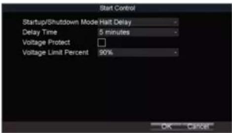
text_image
Start Control Startup/Shutdown Mode Halt Delay Delay Time 5 minutes Voltage Protect Voltage Limit Percent 90%Figure 16-2 Start Control
Step 2 Select Startup/Shutdown Mode as Halt Delay.
Step 3 Select Delay Time. The delay time ranges from 0 to 6 hours.
Step 4 Optionally, check Voltage Protect and select Voltage Limit Percent. If the voltage of the device reaches the selected threshold, the device will shut down automatically.
Step 5 Click OK.
16.3 Reboot
Step 1 Go to Menu > Maintenance.
Step 2 Click Reboot and click Yes on confirmation message box to reboot the device.

Chapter 17 Remote Control
Purpose:
The device can be controlled via IR remote control and mouse.
17.1 Buttons Description
Before you start:
Batteries (2×AAA) must be installed before operation.

text_image
1 2 3 4 5 6 7 8 9 10 11 12 13 14 15 16 17| 4 | Edit | ● Enter the edit status, and then delete the character in the front of the cursor. ● Check a checkbox. ● Clip videos In Playback mode. |
| 5 | A | Switch the input method when editing text field. |
| 6 | REC | Reserved. |
| 7 | PLAY | Enter video search interface. |
| 8 | INFO | Reserved. |
| 9 | VOIP/MON | Reserved. |
| 10 | MENU | Enter Main menu interface. |
| 11 | PREV | In live view, switch screen mode as single screen or multi-screen. |
| 12 | Direction buttons | ● Navigate between fields and items in menus. ● In playback interface, do fast forward, slow forward, and reverse play operations. ● In live view mode, switch among channels. |
| Enter | ● Check a checkbox. ● In playback mode, play or pause the video. ● In auto-switch mode, stop /start auto switch. | |
| 13 | PTZ | Reserved. |
17.2.1 Build Connection with Device (Device No.: 255)
Purpose:
If the device number default one (255), press DEV to build connection between remote control and device.
17.2.2 Build Connection with Device (Device No. is not 255)
Purpose:
Follow the steps to build connection between remote control and device when device number is not 255.
Step 1 Go to Menu > Other Settings > Display.
Step 2 Click Set of Advanced Settings to view device number.
Step 3 Press DEV on the remote control.
Step 4 Enter the device number.
Step 5 Press ENTER on the remote control.
17.2.3 Enter Contents in Text Field
Step 1 Press Left/Right to position the cursor in the text field.
Step 2 Press Enter to edit.
Step 3 Press Edit to delete the previous content.
Step 4 Press A to switch input method.
Step 2 Press Enter to pop up dropdown list.
Step 3 Press Up/Down to select an item.
Step 4 Press Enter to select it.
17.3 Troubleshooting
Purpose:
If there is no response after you press any button on the remote, follow the procedure below to troubleshoot.
Step 1 Go to Menu > Other Settings > Display
Step 2 Click Set of Advanced Settings.
Step 3 Edit device number. The default number is 255.
Step 4 Press DEV on the remote control.
Step 5 Enter the device number.
Step 6 Press ENTER on the remote control.
17.4 Set Areas with Remote Control
Step 1 Click the Area Settings button.
Step 2 Press the Edit key on the remote control and a red block appears on the screen.
Chapter 18 Appendix
18.1 Glossary
- 3G/4G: 3G/4G refers to the 3rd/4th-generaon telecommunicaon technology which is the high speed transmission of the cell data. The 3G/4G service can transmit sound and other data simultaneously and the bitrate is up to hundreds kbps.
- DHCP: DHCP is the acronym of Dynamic Host Conguraon Protocol, and it is one of the TCP/IP protocol stacks, it is used to assign the dynamic IP address to the host on the network.
- Dual Stream: Dual stream is a technology used to record high resolution video locally while transming a lower resolution stream over the network.
- GNSS: A satellite navigaon system is a system of satellites that provide autonomous geo-spaal posioning with global coverage. It allows small electronic receivers to determine their locaon (longitude, latitude, and altitude) to high precision (within a few meters) using me signals transmied along a line of sight by radio from satellites. The signals also allow the electronic receivers to calculate the current local me to high precision, which allows me synchronizaon. A satellite navigaon system with global coverage may be termed GNSS (Global Navigaon Satellite System).
● GPS: GPS (Global Posioning System) is a space-based global navigaon satellite system that provides locaon and me informaon in all weather and anywhere on or near the earth, where there is an unobstructed line of sight to 4 or more GPS satellite. - G-Sensor: G-sensor (Gravity-sensor) can sense the change of the accelerated force, such as the shaking, free falling and liing. And those changes of the accelerated force can be sensed by the G-sensor in a means of electrical signals, and then link certain acon according to the changes of the electrical signals. When applied in the hard disk protecon, G-Sensor can check the current status of the hard disk in case of the aecon of the R/W funcon by the sudden change of the accelerated force.
- NTP: NTP is Network Time Protocol, and it is a protocol used to synchronize the computer me.
- Sensor-In: Sensor-In is a built-in module on the device used to record the movement informaon of the vehicle, such as the braking, le-turning and right-turning and so on. The informaon can be used for analysis of an accident.
- Transparent Channel: Transparent channel is a mechanism which analyzes the IP datagram and sends it by the serial interface. It extends the control distance of the serial devices and for the user, only the point to point transmission is seen and the actual transmission is ignored.
- VPDN: Virtual Private Dial-up Network is a network that uses primarily public telecommunicaon infrastructure, such as the internet, to provide remote oce or travelling users' access to a central organizaon network, such as the ISP private network, nancial network and so on.
Network Video Recorder Quick Start Guide
- Wi-Fi: Wi-Fi is a mechanism of the wireless connecng electronic devices. A device enabled with Wi-Fi such as PC, video game console, can connect to the internet via a wireless network access point.
18.2 FAQ
• Why does my device make a beeping sound aer boong?
The possible reasons for the warning beep on the device are as follows:
a) There is no HDD installed in the device.
b) The HDD is not inialized.
c) HDD error
To cancel the beeping sound and use the device without HDD, enter the Excepon Sengs interface.
- Device fails to start up aer connecng the power.
Possible reasons:
a) Incorrect voltage input (6 \~ 36 VDC) and power consumption (≥ 50W).
b) The HDD lock is not closed.
c) The power connecons are incorrect.
d) The motherboard or power funcons abnormally. In case of hardware failure, please contact the supplier of the product.
- Fail to connect 3G/4G.
Possible reasons for 3G/4G conneccon failure are as follows:
a) Dialing is not enabled.
b) APN, dial number, user name and password should be set for 3G/4G VPDN private network.
c) No 3G/4G antenna connected. When both the master/slave antennas are connected, locate them vertically with above 20cm distance from each other.
d) SIM card is out of service or 3G/4G service is not opened.
- Fail to connect to Wi-Fi.
Please check the following sengs:
a) The SSID, encrypon type or password are entered incorrectly.
b) AP (access point) or router works abnormally.
c) No Wi-Fi antenna connected or the antenna is not vercally located.
- The device cannot be accessed via platform (IVMS) after successful connection to 3G/4G or Wi-Fi.
Possible reasons:
a) The parameters (e.g., server IP, device registered ID, etc.) of the platform are configured incorrectly.
b) The platform works abnormally.
• Fail to obtain satellite positioning information.
Possible reasons:
a) The satellite positioning antenna is not placed outdoor.
b) There is no satellite positioning module (built-in or external) available for the device.
c) The Position Module are configured incorrectly.
• Why does the device seem unresponsive when operating with the IR remote control?
a) The batteries are installed correctly, making sure that the polarities of the batteries are not reversed.
b) The batteries are fresh and are not out of power.
c) The remote sensor is not covered or blocked by other object.
d) There are no fluorescent lamps in use nearby.
• No backup device is detected when exporting recorded files?
Possible reasons:
a) There is no backup device connected with the device.
Network Video Recorder Quick Start Guide