QT848 - Security Camera Q-See - Free user manual and instructions
Find the device manual for free QT848 Q-See in PDF.

| Product Type | Security Camera |
| Brand | Q-See |
| Model | QT848 |
| Image Sensor | 1/3" CMOS |
| Resolution | 1080p (1920x1080) |
| Lens | 3.6mm fixed lens |
| Night Vision | Up to 100 ft (30m) with IR LEDs |
| Field of View | 80° horizontal |
| Video Output | 1x BNC (analog), 1x HDMI (optional) |
| Power Supply | 12V DC, 1A |
| Power Consumption | 6W |
| Dimensions (W x H x D) | 2.8" x 3.2" x 4.5" (71 x 81 x 114 mm) |
| Weight | 0.5 lb (227 g) |
| Mounting Type | Wall or ceiling mount (bracket included) |
| Weather Rating | IP66 (outdoor use) |
| Operating Temperature | -22°F to 140°F (-30°C to 60°C) |
| Motion Detection | Yes, with adjustable sensitivity |
| Compatible Systems | Q-See DVRs, most analog DVRs |
| Audio Support | Built-in microphone (audio input) |
| Care and Cleaning | Clean lens with soft, dry cloth. Avoid harsh chemicals. |
| Safety Precautions | Use a surge protector. Do not expose to heavy rain or submersion. |
| Spare Parts Availability | Replacement cables and brackets available online |
| Repairability | Limited user serviceable parts; contact customer support |
| Warranty | 1 year limited |
Frequently Asked Questions - QT848 Q-See
User questions about QT848 Q-See
0 question about this device. Answer the ones you know or ask your own.
Ask a new question about this device
Download the instructions for your Security Camera in PDF format for free! Find your manual QT848 - Q-See and take your electronic device back in hand. On this page are published all the documents necessary for the use of your device. QT848 by Q-See.
USER MANUAL QT848 Q-See
natural_image
Exterior view of a black Qsee audio equipment unit with control buttons and drive dials (no readable text or symbols beyond branding)
text_image
QT SERIES
Thank You for Choosing a Q-See Product!
All of our products are backed by a conditional service warranty covering all hardware for 12 months from the date of purchase. Additionally, our products also come with a free exchange policy that covers all manufacturing defects for one month from the date of purchase.
Permanent upgrading service is provided for the software and is available at www.Q-See.com.
Be certain to make the most of your warranty by completing the registration form online. In addition to warranty and technical support benefits, you'll receive notifications of product updates along with free downloadable firmware updates for your DVR. Register today at www.Q-See.com!
Please see the back of this manual for exclusions.

text_image
ONLINE PRODUCT REGISTRATION Register your product to receive important downloads and updates. www.q-see.com Qsee© 2010-2014 Q-See. Reproduction in whole or in part without written permission is prohibited. All rights reserved. This manual and software and hardware described herein, in whole or in part, may not be reproduced, translated, or reduced to any machine-readable form without prior written approval.
Trademarks: All brand names and products are trademarks or registered trademarks of their respective owners.
Q-See is a registered trademark of DPS, Inc.
Disclaimer: The information in this document is subject to change without notice. The manufacturer makes no representations or warranties, either express or implied, of any kind with respect to completeness of its contents.
Manufacturer shall not be liable for any damages whatsoever from misuse of this product.
About this Manual
This manual is written for the QT family of Conventional and SDI DVRs. Not all features and capabilities are shared across all models so you may see features described which are not applicable or available on your machine. In addition you may see screen images that do not exactly match those on your display.
This manual was accurate at the time it was completed. However, because of our ongoing effort to constantly improve our products, features and functions may have been added or changed since that time and on-screen displays may change. We encourage you to visit our website at www.Q-See.com to check for the latest firmware updates and product announcements.
Throughout the manual we have highlighted warnings and other important information that will assist you in operating your new system in a safe and trouble-free manner. Please take the time to read and follow all instructions and pay attention to alerts as shown below:

IMPORTANT! Red boxes with this icon indicate warnings. To prevent possible injury or damage to the product, read all warnings before use.

NOTE! Text in blue boxes with the Information icon offer additional guidance and explanations about how to make the most out of your system.
AN IMPORTANT NOTE ABOUT CONVENTIONAL AND SDI SYSTEMS
Depending upon the model, your DVR is equipped to work with conventional analog cameras or digital high definition SDI (Serial Digital Interface) cameras. Both cameras use similar cables and connectors, (see Section 2.5 for connection instructions) but they are not interchangeable as they are two completely different - and incompatible - technologies. If you are adding cameras beyond those that came packaged with your DVR, be sure to check that they are compatible with your system.
Aside from this, the operation of the DVR is identical regardless of the technology. The primary difference is in resolution. While recent breakthroughs in analog video technology have allowed conventional cameras to be able to deliver resolutions up to 1000 TVL (Television Lines) as of this writing, Q-See's SDI cameras record in 720p and 1060p high definition which offers the advantage of a higher pixel count and no loss of clarity due to having to convert the video signal between digital and analog formats. Similarly, the conventional DVRs can only record files up to the D1 (704x480 pixels) or 960H formats (960x480 pixels) while the SDI systems will record in formats up to 1060p (1920x1080 pixels).
Rev. 4.5 12/30/2013
TABLE OF CONTENTS
An Important Note about conventional and SDI Systems 3
1. INTRODUCTION 7
For Your Safety 7
Features
[Non-Text]
2. CONNECTIONS AND CONTROLS 10
2.1 DVR Functions and Connections 10
QT228 11
QT2124 12
QT454 14
QT474 16
QT426 18
QT428 20
QT446 22
QT4332 QT4532 24
QT4516 26
QT504 28
QT526 30
QT528 32
QT518 34
QT5116 36
QT534 38
QT536 40
QT548 & QT578 42
QT4760 44
QT5024 46
QT5032 48
QT5132 50
QT5140 & QT5440 52
QT5516 & QT5616 54
QT5680 & QT5682 56
QT5716 58
QT704 & QT714 60
QT718 62
QT724 64
QT728 66
QT7116 68
2.2 Mouse 70
2.3 Remote Control 71
2.4 Video Display 75
Connecting a Video Display 75
'Missing' Menu 77
Multiple Monitors and Spot Out 77
2.5 Cameras 78
Connecting Cameras 78
Camera Placement 79
Additional Considerations
960H Cameras
80
81
3. BASIC FUNCTIONS 82
3.1 Power On/Off 82
Power On and Login
Power Off
82
82
3.2 The Control Bar 83
3.3 Live Viewing and Recording 86
Switching Video Output
Live Viewing
Recording
86
86
3.4 Quick Playback 87
4. MAIN MENU SETUP 90
4.1 Basic Configuration 90
Menu Navigation
Setup
90
4.2 Live Configuration 93
4.3 Record Configuration 95
4.4 Schedule Configuration 98
4.5 Network Configuration 99
4.6 User Management 103
User accounts and Passwords
103
Time Search
105
Event Search
106
File Management
106
Image
107
5. BACKUP 108
Formatting a USB Drive in FAT32 108
Backing Up a File
108
Playing Back a Video File on a Computer
109
Important Considerations
109
6. DVR MANAGEMENT 110
6.1 Information 110
Event Information
111
Log Information
111
Network Information
111
Online User Information
112
6.2 Manual Alarm 113
6.3 Disk Management 113
6.4 Firmware Upgrade 114
6.5 Logoff 115
6.6 Shut Down 115
7. PAN/TILT/ZOOM CAMERAS 116
7.1 Connecting a PTZ Camera 116
7.2 Pan-Tilt-Zoom (PTZ) Configuration 117
8. ALARMS 120
8.1 Alarm Input 120
8.2 Alarm Output 122
8.3 Alarm Configuration 123
Sensor 123
Motion
Video Loss 125
Other Alarm
Alarm Out
124
125
126
9. HARD DISK DRIVE 127
9.1 Installation/Removal
9.2 Calculating the Recording Capacity of a Hard Drive
127
129
APPENDIX 130
A.1 Troubleshooting
A.2 Specifications
A.3 Rack Mounting
130
133
146
Q-SEE PRODUCT WARRANTY 147
Questions or Comments? Contact Us
148
INTRODUCTION
CHAPTER 1
FOR YOUR SAFETY
To prevent damage to your Q-See product or injury to yourself or to others, read and understand the following safety precautions in their entirety before installing or using this equipment. Keep these safety instructions where all those who use the product will read them.

WARNING! ELECTRIC SHOCK RISK!

- Check the unit and any accessories included in the package immediately after opening. If items are missing or damaged, repackage and return to the point of purchase.
Use the proper power source. Only use the power adapter supplied with your system. Do not use this product with a power source that applies more than the specified voltage (100-240V AC).
■ Never insert anything metallic into the DVR. Inserting anything into the DVR or its case can be a source of dangerous electric shock.
■ Do not operate in dusty areas. Avoid placing the DVR in places that are dusty.
Do not expose this product to rain or use near water. If this product accidentally gets wet, unplug it and contact Q-See immediately. - Keep product surfaces clean and dry. To clean the outside case of the DVR, gently wipe using a lightly dampened cloth (only use water, do not use solvents).
- Do not operate this DVR without the cover securely in place. Do not attempt to do any repairs to the DVR yourself. If there are unusual sounds or smells coming from the DVR, unplug it immediately and contact Q-See technical support. Under no circumstances should the cover be removed while the device is connected to a power source. You should only remove the cover to install/replace the hard disk drive (See Chapter 9) or replace the standard 3v lithium cell battery on the motherboard. These are the only user serviceable parts. You may need to replace the battery if the internal clock resets itself after a power outage
- Handle the DVR carefully. If you accidentally drop your DVR on any hard surface, it may cause a malfunction. If the DVR doesn't work properly due to physical damage, contact an authorized dealer for repair or exchange.
■ Make sure there is proper air circulation around the unit. This DVR system uses a hard drive for video storage which generates heat during operation. Do not block air holes located on the bottom, top, sides and back of the DVR as they are designed to keep the system cool while running. Install or place this product in an area where there is ample air circulation.
■ Provide proper ventilation. This DVR has a built-in fan that properly ventilates the system. Do not cover or impede this fan.
FEATURES
This DVR uses high-performance video processing chips and an embedded Linux operating system for quality image recording and ease of use. It utilizes numerous advanced technologies including the industry-standard H.264 compression to deliver high-quality, smooth videos and dual stream capability for remote viewing. A SATA hard-drive interface offers upgradability and two video outputs allows for the choice of viewing on a VGA monitor or a standard TV. In addition, some models include an HDMI video port for HD viewing.
Local control of the system utilizes a mouse and graphical user interface (GUI) as well as a remote control. Users can also remotely monitor and control their system using a web browser or select mobile device.
This DVR uses cutting-edge technology without compromising stability and reliability making it ideal for home use as well as in warehouse, factory, retail and other similar environments.
COMPRESSION FORMAT
Standard H.264 compression with low bit rate and high image quality
LIVE SURVEILLANCE
Supports VGA and RCA output. Some models also support HDMI
Supports channel security by hiding live display
Displays the local record state and basic information
Supports full control with USB mouse
Supports digital zoom on live and playback view
RECORDING MEDIA
Supports SATA hard disk drives up to 3TB each for longer recording times.
BACKUP
Supports backing up to USB 2.0 devices
Some models support eSATA external hard drives
Supports saving recorded files with AVI format to a remote computer through internet
Record modes: Manual, Schedule, Motion detection and Sensor alarm recording
Supports recycle after HDD is full
Resolution, frame rate and picture quality are adjustable
128MB for every video file packaging
Up to 16 audio channels available depending on model
Two record search modes: time search and event search
Supports multi-screen simultaneous playback
Supports deleting and locking the recorded files one by one
Supports remote playback in Network Client through LAN or internet
Analog models support recording in CIF, D1 resolutions.
SDI models support recording in 720P and 1080P HD resolutions.
ALARM
1-4 channel alarm output and up to 16-channel (depending on model) alarm input available
Supports scheduling for motion detection and sensor alarm
Supports pre-recording and post recording
Supports linked channels recording once motion or alarm is triggered on designated channel
Supports linked PTZ preset, and auto cruise
PTZ CONTROL
Supports multiple PTZ protocols (PelcoP, PelcoD, LILIN, MINKING, NEON, STAR, VIDO, DSCP, VISCA, and RANGE)
Supports 128 PTZ presets and 8 auto cruise tracks
Supports remote PTZ control through internet
SECURITY
Customize user rights: log search, system setup, two way audio, file management, disk management, remote login, live view, manual record, playback, PTZ control and remote live view
Supports 1 administrator and 15 users.
Supports event log recording and checking, events unlimited
NETWORK
Supports TCP/IP, DHCP, PPPoE, DDNS
Supports Internet Explorer and Safari browsers to do remote viewing
Supports a maximum of 10 user connections simultaneously
Supports dual stream. Network stream is adjustable independently to fit the network bandwidth and environment.
Supports picture snap and color adjustment in remote live view
Supports remote time and event search, and channel playback with picture snap
Supports remote PTZ control with preset and auto cruise
Supports remote full menu setup, changing all the DVR parameters remotely
Supports mobile surveillance by smart phones, Win Mobile Pro, Win 7 Mobile,
Symbian, and iPhones, iPads, Android, and Blackberry on 3G networks
Supports CMS to manage multiple devices over the internet
Administrator can limit user access to specific cameras
Administrator can disconnect online users

NOTE! Depending on your point of purchase, your DVR may have the hard disk drive already installed. If your drive was packaged separately or if you wish to upgrade to up to a larger hard drive, please see Chapter 9 at the back of this manual which covers installing the drive.
CONNECTIONS AND CONTROLS CHAPTER 2
You may view this DVR using a standard 19" (or larger) VGA monitor or a television. The former is connected using the VGA port on the back panel while the television utilizes the BNC "Video Out" port on the back. Your DVR is configured to use the VGA port as the main display. To use a TV, you will need to press and hold the STOP/ESC, EXIT or VGA/TV button (depending on model) for approximately 10 seconds until you hear a beep indicating that the video mode has been switched. A display connected to the other port will not show the menu.
2.1 DVR FUNCTIONS AND CONNECTIONS
QT228
FRONT PANEL
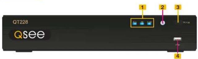
text_image
QT228 Qsee 1 2 3 4ITEM NAME FUNCTION
| 1 INDICATOR LIGHTS | Shows the recording, network and power status of the DVR. |
| 2 INFRARED WINDOW | Receives signals from the remote control |
| 3 VIDEO MODE BUTTON | Press and hold 10 seconds (or until you hear a beep) to switch video output from the VGA port (default) to the BNC video out port. |
| 4 USB PORT Used for external USB backup devices. | |
REAR PANEL

text_image
1 AUDIO IN 2 NERO IN 3 AUDIO OUT 4 VIDEO OUT 5 VGA 6 HDMI 7 USB 8 DC12V 9ITEM NAME FUNCTION
| 1 AUDIO IN 1 Channel of audio input |
| 2 VIDEO IN Video input from up to 8 cameras |
| 3 AUDIO OUT RCA Audio output for amplified speaker |
| 4 VIDEO OUT BNC connector for TV or monitor |
| 5 VGA PORT VGA output for 19" or larger monitor |
| 6 HDMI HDMI video output |
| 7 LAN Network (ethernet) port |
| 8 USB PORT For the USB mouse |
| 9 DC IN Power input for 12V DC power supply |
QT2124
FRONT PANEL
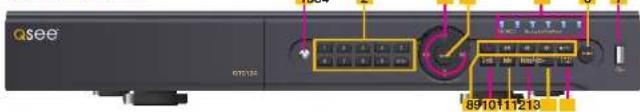
text_image
Qsee 891011213| ITEM | NAME | FUNCTION |
| 1 | IR RECEIVER | Receives signals from remote control |
| 2 | NUMBER BUTTONS | Select individual channels for full screen view |
| 3 | DIRECTION | Selects multi-screen viewing modeNavigates through selections in menus |
| 4 | ENTER | Confirm Selection |
| 5 | INDICATOR LIGHTS | Shows status of the DVR Functions and the Hard Drive |
| 6 | MENU | Opens the Main MenuIncreases the value in Setup mode |
| 7 | USB PORT | Used for external USB backup devices. |
| 8 | PLAYBACK CONTROLS | In addition to normal DVR playback and record operation, the following have additional functions:RECORD Controls Focus in PTZ modeREVERSE Controls Speed in PTZ modeSTOP/ESC Exits current interface or statusAlso switches video output mode. |
| 9 | SEARCH/ZOOM | Enter Search modeControls Zoom function in PTZ mode |
| 10 | INFO | Displays system information |
| 11 | BACKUP | Enter Backup modeDecreases the value in Setup mode |
| 12 | AUDIO | Mutes or unmutes audio |
| 13 | PTZ | Enter PTZ mode |
BACK PANEL

text_image
1 2 3 4 5 6 7 8 9 10 11 12 13| ITEM | NAME | FUNCTION |
| 1 | VGA PORT | VGA output for 19" or larger monitor |
| 2 | VIDEO OUT | BNC connector for TV or monitor |
| 3 | VIDEO IN | BNC connectors for up to 24 cameras |
| 4 | PTZ | Connections for Pan-Tilt-Zoom speed dome cameras. Y = "+" Z = "-" |
| 5 | AUDIO IN | 4 channels of audio input |
| 6 | FAN | Cooling fan exhaust port. This should not be blocked. |
| 7 | NET | Network (ethemet) port |
| 8 | USB PORT | For the USB mouse |
| 9 | SPOT OUT | Connect to another monitor as an auxiliary output channel. This monitor will only display video and will have no menu access. |
| 10 | K/B | Connector for a PTZ keyboard |
| 11 | ALARM OUT | I Channel relay output for external alarm |
| 12 | ALARM IN | Connections for up to 16 external sensors |
| 13 | DC IN | Power input for 12V DC power supply |
QT454
FRONT PANEL
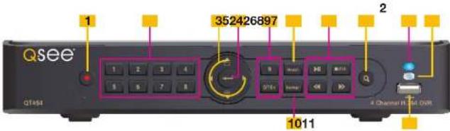
text_image
Qsee 352426897 1 2 3 4 5 6 7 8 9 10 11 QTEs P0 OK Q Q Channel R 104 DUT| ITEM NAME | FUNCTION | |
| 1 | POWER | Power On/Off |
| 2 | NUMBER BUTTONS | Select individual channels and enter data where required |
| 3 | DIRECTION | Navigates through selections in menusSelects viewing mode - Full Screen or 4-Channel Multi-Screen View |
| 4 | ENTER | Confirm Selection |
| 5 | MENU | Opens the Main MenuIncreases the value in Setup mode |
| 6 | PLAYBACK CONTROLS | In addition to normal DVR playback and record operation, the following have additional functions:RECORD Controls Focus in PTZ modeREVERSE Controls Speed in PTZ modeSTOP/ESC Exits current interface or statusAlso switches video output mode. |
| 7 | SEARCH/ZOOM | Enter Search modeControls Zoom function in PTZ mode |
| 8 | INDICATOR LIGHT | Shows power status of the DVR |
| 9 | INFRARED WINDOW | Receives signals from the remote control |
| 10 | BACKUP | Enter Backup modeDecreases the value in Setup mode |
| 11 | USB PORT | Used for external USB backup devices. |
REAR PANEL
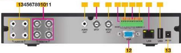
text_image
134567891011 AUDIO OUT SPECT VIDEO OUT VISA LAN USB NC CN 12 13| ITEM NAME | FUNCTION | |
| 1 | AUDIO IN | 4 Channels of audio input |
| 2 | VIDEO IN | Video input from up to 4 cameras |
| 3 | AUDIO OUT | Audio output for amplified speaker |
| 4 | SPOT OUT | Connect to another monitor as an auxiliary output channel. This monitor will only display video and will have no menu access. |
| 5 | VIDEO OUT | BNC connector for TV or monitor |
| 6 | PTZ | Connections for Pan-Tilt-Zoom speed dome cameras. Y = "+" Z = "-" |
| 7 | K/B | Connector for a PTZ keyboard |
| 8 | ALARM OUT | 1 Channel relay output for external alarms |
| 9 | ALARM IN | 4 Channel input for external sensors and alarms |
| 10 | LAN | Network (ethernet) port |
| 11 | USB PORT | For the USB mouse |
| 12 | VGA PORT | VGA output for 19" or larger monitor |
| 13 | DC IN | Power input for 12V DC power supply |
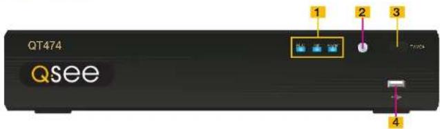
QT474
FRONT PANEL
text_image
QT474 QseeITEM NAME FUNCTION
| 1 INDICATOR LIGHTS | Shows the recording, network and power status of the DVR. |
| 2 INFRARED WINDOW | Receives signals from the remote control |
| 3 VIDEO MODE BUTTON | Press and hold 10 seconds (or until you hear a beep) to switch video output from the VGA port (default) to the BNC video out port. |
| 4 USB PORT Used for external USB backup devices. | |
REAR PANEL

text_image
1 2 3 4 5 6 7 8 9 10ITEM NAME FUNCTION
| 1 AUDIO IN 2 Channels of audio input | ||
| 2 VIDEO IN Video input from up to 4 cameras | ||
| 3 VIDEO OUT BNC connector for TV or monitor | ||
| 4 VGA PORT VGA output for 19" or larger monitor | ||
| 5 POWER SWITCH | Use to turn on the DVR as well as to turn off after powering down from within the GUI | |
| 6 AUDIO OUT BNC Audio output for amplified speaker | ||
| 7 LAN Network (ethemet) port | ||
| 8 USB PORT For the USB mouse | ||
| 9 PTZ Connections for Pan-Till-Zoom speed dome cameras. | ||
| 10 DC IN Power input for 12V DC power supply | ||
QT426
FRONT PANEL

text_image
FRONT PANEL OPTION QSEE 16 Channel H-264 TWR 1 2 12345| ITEM | NAME | FUNCTION |
| 1 | LED INDICATORS | Show status of power, HDD, record, etc. |
| 2 | IR RECEIVER | Receives signals from remote control |
| 3 | RECORD | Manually begins recording |
| 4 | PLAY | Launches PLAYBACK window |
| 5 | REW | Rewind key |
| 6 | FF | Fast Forward |
| 7 | +/MENU | Increase the value in SETUP/Enter menu in LIVE VIEW |
| 8 | -/BACKUP | Decrease the value in SETUP/Enter backup mode in LIVE VIEW |
| 9 | STOP/ESC | Quit PLAYBACK mode/Exit the current window or statusAlso switches video output mode. |
| 10 | ENTER | Confirm selection |
| 11 | DIRECTION/MULTISCREEN | 1. Navigate through on-screen options2. Change screen display mode between 1, 4, 9 and 16 channels |
| 12 | USB | USB port to connect USB flash or external hard drives to update firmware or back up recordings |
REAR PANEL

text_image
1 2 34 5 6 7 8910 1112 VIDEO IN 13 14| ITEM | NAME | FUNCTION |
| 1 | AUDIO OUTPUT | Connection for audio output – connect to an amplified speaker |
| 2 | AUDIO IN | 4-Channel audio input for cameras equipped with audio |
| 3 | VGA PORT | Video output for connecting to monitor |
| 4 | VIDEO OUT | Video output for connecting to TV (BNC) or monitor |
| 5 | RS485 | Connect to Pan-Tilt-Zoom camera to control motion |
| 6 | K/B | Connect to keyboard |
| 7 | ALARM OUTPUT | Output for alarm |
| 8 | +5 AND GND | +5 and grounding |
| 9 | ALARM IN | Connect to up to sixteen external sensors |
| 10 | USB PORT | Connect USB mouse |
| 11 | NET | Network (ethernet) port |
| 12 | SPOT | Connect to another monitor as an auxiliary output channel. This monitor will only display video and will have no menu access. |
| 13 | VIDEO IN | Video input from up to 16 cameras |
| 14 | DC +12V | Power input |
QT428
FRONT PANEL

text_image
123456789 QSee 101211| ITEM | NAME | FUNCTION |
| 1 | RECORD | Manually begins recording |
| 2 | PLAY | Launches PLAYBACK window |
| 3 | REW | Rewind |
| 4 | FF | Fast Forward |
| 5 | +/MENU | Increase the value in SETUP/Enter menu in LIVE VIEW |
| 6 | -/BACKUP | Decrease the value in SETUP/Enter backup mode in LIVE VIEW |
| 7 | STOP/ESC | Quit PLAYBACK mode/Exit the current window or statusAlso switches video output mode. |
| 8 | LED INDICATORS | Show status of power, HDD, record, etc. |
| 9 | IR RECEIVER | Receives signals from remote control |
| 10 | DIRECTION/MULTISCREEN | 1. Navigate through on-screen options2. Change screen display mode between 1, 4, and 9 channels |
| 11 | ENTER | Confirm selection |
| 12 | USB | USB port to connect USB flash or external hard drives to update firmware or back up recordings |
REAR PANEL

text_image
1 2 3 4 5 6 7 8 9 10 11 12 13| ITEM | NAME | FUNCTION |
| 1 | VIDEO OUT | Video output for connecting to TV (BNC) or monitor |
| 2 | SPOT | Connect to another monitor as an auxiliary output channel. This monitor will only display video and will have no menu access. |
| 3 | AUDIO OUTPUT | Connection for audio output – connect to an amplified speaker |
| 4 | VIDEO IN | Video input from up to 8 cameras |
| 5 | DC +12V | Power input |
| 6 | VGA PORT | Video output for connecting to monitor |
| 7 | LAN | Network (ethernet) port |
| 8 | USB PORT | Connect USB mouse |
| 9 | RS485 | Connect to Pan-Tilt-Zoom camera to control motion |
| 10 | K/B | Connect to keyboard |
| 11 | ALARM OUTPUT | Output for alarm |
| 12 | ALARM IN | Connect to up to eight external sensors |
| 13 | AUDIO IN | 4-Channel audio input for cameras equipped with audio |
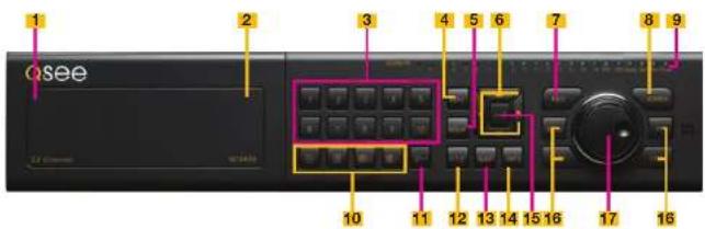
QT446
FRONT PANEL
text_image
Qsee 1 2 3 4 5 6 7 8 9 10 11 12 13 14 15 16 17 16 18 Channel N: 184.5WITEM NAME FUNCTION
| 1 | POWER (Behind flip-down panel) | Puts the DVR into standby mode or wakes it up from standby mode. |
| 2 | USB PORT(Behind flip-down panel) | Used for external USB backup devices. |
| 3 | NUMBER PAD Enter channel numbers. | |
| 4 | MENU Opens the Main Menu | |
| 5 | BACKUP Opens Backup Menu | |
| 6 DIRECTION Navigates through selections in menus | ||
| 7 | RECORD Begins manually recording on all channels | |
| 8 | SEARCH Enters Search Mode | |
| 9 | INDICATOR LIGHTS Shows status of the DVR Functions and the Hard Drive | |
| 10 | VIEWING MODE Change between 1, 4, 8 and 16-screen viewing mode | |
| 11 | 10+ BUTTON Input channels numbers above 10 by pushing this button followed by the second digit. | |
| 12 | PTZ Enter PTZ mode in live view | |
| 13 | AUDIO | Turn audio on or off in live view if audio input devices are attached. |
| 14 | INFO | Displays system Information |
| 15 | ENTER | Confirms selection in menus or input in fields |
| 16 | PLAYBACK CONTROLS | REW - RowindPLAY - Opens the Playback Interface, Pauses or resumes playbackFF - Fast ForwardSTOP - Quits Playback modeAlso switches video output mode. |
| 17 | CONTROL KNOB | Outer ring navigates through menusInner knob increases or decreases speed of fast forward or rewind. |
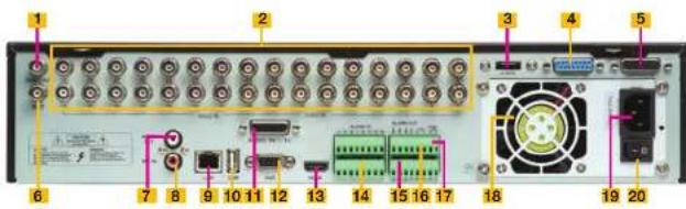
BACK PANEL
text_image
Labeled diagram of a network equipment rack with numbered components and portsITEM NAME FUNCTION
| 1 VIDEO OUT | BNC connector for TV or monitor | |
| 2 VIDEO IN | BNC connectors for up to 16 cameras | |
| 3 | eSATA (2) | Connection for external eSATA hard drive for backup |
| 4 POWER SOCKET | Attachment point for power cord | |
| 5 LOOP OUT (2) | Output each channel to a separate monitor. Each port handles 8 channels. | |
| 6 SPOT OUT | Connect to another monitor as an auxiliary output channel. This monitor will only display video and will have no menu access. | |
| 7 AUDIO IN | 16 channels of audio input | |
| 8 AUDIO OUT | Audio output for amplified speaker | |
| 9 MICROPHONE IN | Connect a microphone for two-way audio | |
| 10 | VGA PORT | VGA output for 19" or larger monitor |
| 11 | USB PORT | For the USB mouse |
| 12 | LAN | Network (ethernet) port |
| 13 | ALARM IN | Connect up to 16 external sensors |
| 14 | ALARM OUT | 4 Channel relay output for external alarms |
| 15 | PTZ Connections for Pan-Tilt-Zoom speed dome cameras. Y = "+" Z = "-" | |
| 16 | K/B | Connector for a PTZ keyboard |
| 17 | POWER SWITCH | Use to turn on the DVR as well as to turn off after powering down from within the GUI |
| 18 | FAN | Cooling fan exhaust port. This should not be blocked. |
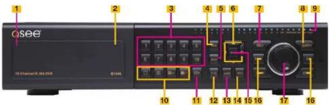
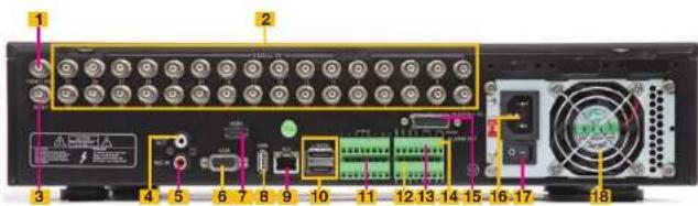
QT4332 QT4532
FRONT PANEL
text_image
Qsee 82 Channel 8.264 GHz 07-0332 1 2 3 4 5 6 7 8 9 10 11 12 13 14 15 16 17 16ITEM NAME FUNCTION
| 1 | POWER (Behind flip-down panel) | Puts the DVR into standby mode or wakes it up from standby mode. |
| 2 | USB PORT(Behind flip-down panel) | Used for external USB backup devices. |
| 3 | NUMBER PAD Enter channel numbers. | |
| 4 | MENU Opens the Main Menu | |
| 5 | BACKUP Opens Backup Menu | |
| 6 DIRECTION Navigates through selections in menus | ||
| 7 | RECORD Begins manually recording on all channels | |
| 8 | SEARCH Enters Search Mode | |
| 9 | INDICATOR LIGHTS Shows status of the DVR Functions and the Hard Drive | |
| 10 | VIEWING MODE Change between 1, 4, 8, 16 and 32-screen viewing mode | |
| 11 | 10+ BUTTON Input channels numbers above 10 by pushing this button followed by the second digit. | |
| 12 | PTZ Enter PTZ mode in live view | |
| 13 | AUDIO | Turn audio on or off in live view if audio input devices are attached. |
| 14 | INFO | Displays system information |
| 15 | ENTER | Confirms selection in menus or input in fields |
| 16 | PLAYBACK CONTROLS | REW - RewindPLAY - Opens the Playback Interface. Pauses or resumes playbackFF - Fast ForwardSTOP - Quits Playback modeAlso switches video output mode. |
| 17 | CONTROL KNOB | Outer ring navigates through menusInner knob increases or decreases speed of fast forward or rewind. |
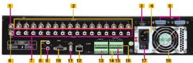
BACK PANEL
text_image
Labeled diagram of a computer rack with numbered components and connectors| ITEM NAME | FUNCTION | |
| 1 VIDEO OUT | BNC | connector for TV or monitor |
| 2 VIDEO IN | BNC | connectors for up to 32 cameras |
| 3 SPOT OUT | Connect to another monitor as an auxiliary output channel. This monitor will only display video and will have no menu access. | |
| 4 AUDIO OUT | Audio output for amplified speaker | |
| 5 MICROPHONE IN | Connect a microphone for two-way audio | |
| 6 VGA PORT | VGA output for 19" or larger monitor | |
| 7 HDMI | HDMI video output | |
| 8 USB PORT For the USB mouse | ||
| 9 LAN | Network (ethemet) port | |
| 10 | eSATA (2) | Connection for external eSATA hard drive for backup |
| 11 | ALARM IN | Connect up to 16 external sensors |
| 12 | ALARM OUT | 4 Channel relay output for external alarms |
| 13 | PTZ | Connections for Pan-Tilt-Zoom speed dome cameras. Y = "+" Z = "-" |
| 14 | K/B | Connector for a PTZ keyboard |
| 15 | AUDIO IN | Attachment point for audio dongle which allows up to 16 channels of audio input. |
| 16 | POWER SOCKET | Attachment point for power cord |
| 17 | POWER SWITCH | Use to turn on the DVR as well as to turn off after powering down from within the GUI |
| 18 | FAN | Cooling fan exhaust port. This should not be blocked. |
QT4516
FRONT PANEL

text_image
Qsee 1 2 3 4 5 6 7 8 9 10 11 12 13ITEM NAME FUNCTION
| 1 RECORD Manually begins recording | ||
| 2 LED | INDICATORS | Show status of power, HDD, record, etc. |
| 3 DIRECTION/MULTISCREEN | 1. Navigate through on-screen options2. Change screen display mode between 1, 4, 9 and 16 channels | |
| 4 IR RECEIVER Receives signals from remote control | ||
| 5 ENTER Confirm selection | ||
| 6 PLAY/PAUSE Launches PLAYBACK window.Starts or pauses video. | ||
| 7 REWIND Reverses video direction | ||
| 8 FAST FORWARD Changes playback speed | ||
| 9 STOP/ESC Quit PLAYBACK mode/Exit the current window or statusSwitch video output mode. (Press and hold 10 seconds) | ||
| 10-/BACKUP Decrease the value in SETUP/Enter backup mode in LIVE VIEW | ||
| 11+/MENU Increase the value in SETUP/Enter menu in LIVE VIEW | ||
| 12 SEARCH Enters Search Mode | ||
| 13 USB | USB port to connect USB flash or external hard drives to update firmware or back up recordings | |
REAR PANEL
text_image
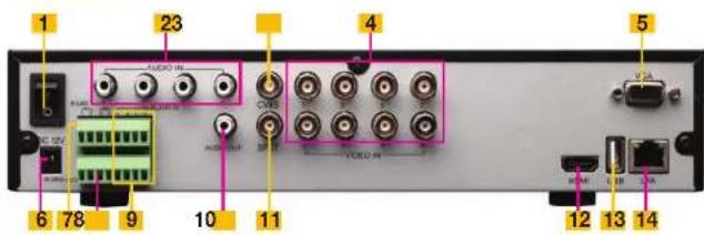
1 2 3 4 5 6 7 8 9 10 11 AUDIO IN AUDIO OUT VICO VIDEO IN VIA HCAI USB LANITEM NAME FUNCTION
| 1 POWER SWITCH | Use to turn on the DVR as well as to turn off after powering down from within the GUI | |
| 2 AUDIO IN | 4 Channel audio input for cameras equipped with audio | |
| 3 CVBS (Video Out) | Video output for connecting to TV (BNC) or monitor | |
| 4 VIDEO IN | Video input from up to 16 cameras | |
| 5 VGA PORT | Video output for connecting to monitor | |
| 6 DC +12V Power input | ||
| 7 PTZ | PTZ camera connection ports | |
| 8 ALARM OUTPUT | Output for alarm | |
| 9 ALARM IN | Connect to up to sixteen external sensors | |
| 10 AUDIO OUTPUT | Connection for audio output – connect to an amplified speaker | |
| 11 | SPOT | Connect to another monitor as an auxiliary output channel. This monitor will only display video and will have no menu access. |
| 12 HDMI | HDMI video output | |
| 13 USB PORT | Connect USB mouse | |
| 14 NET | Network (ethernet) port | |
QT504
FRONT PANEL

text_image
1 2 3 4 5 6 7 8 9 10 11 12ITEM NAME FUNCTION
| 1 | RECORD | Begins manual recordingControls Focus in PTZ mode |
| 2 | PLAY | Begins playback |
| 3 | REWIND | Rewinds videoControls camera speed in PTZ mode |
| 4 | FAST FORWARD | Advances playback speed |
| 5 | MENU/+ Opens the Main MenuIncreases the value in Setup mode | |
| 6 | BACKUP/- | Opens Backup MenuDecreases the value in Setup mode |
| 7 | STOP/ESC | Ends video playback.Exits current interface or statusSwitches video output mode. |
| 8 | INDICATOR LIGHTS Shows status of the DVR Functions and the Hard Drive | |
| 9 IR RECEIVER Receives signals from remote control | ||
| 10 DIRECTION Selects multi-screen viewing modeNavigates through selections in menus | ||
| 11 RETURN Confirms selection | ||
| 12 USB PORT Used for external USB backup devices. | ||
BACK PANEL
text_image
1 2 3 4 5 6 7 8 9 10 11 12 13ITEM NAME FUNCTION
| 1 VIDEO OUT BNC connector for TV or monitor | |
| 2 SPOT OUT Connect to another monitor as an auxiliary output channel. This monitor will only display video and will have no menu access. | |
| 3 AUDIO OUT Audio output for amplified speaker | |
| 4 VIDEO IN | BNC connectors for up to 4 cameras |
| 5 DC IN | Power input for 12V DC power supply |
| 6 VGA PORT VGA output for 19" or larger monitor | |
| 7 NET | Network (ethernet) port |
| 8 USB PORT For the USB mouse | |
| 9 PTZ | Connections for Pan-Tilt-Zoom speed dome cameras. Y = +" Z = "-" |
| 10 K/B | Connector for a PTZ keyboard |
| 11 +5V and GND | +5V and grounding |
| 12 ALARM IN/OUT | 4 Channel input and output for external sensors and alarms |
| 13 AUDIO IN | 4 channels of audio input |
QT526
FRONT PANEL

text_image
Qsee 1 2 3 4 5 6 7 8 9 10 11 12 13 Q See Control Producer Server DBS ETSITEM NAME FUNCTION
| 1 IR RECEIVER Receives signals from remote control | |
| 2 NUMBER BUTTONS Select individual channels for full screen view | |
| 3 DIRECTION Selects multi-screen viewing modeNavigates through selections in menus | |
| 4 ENTER Confirm Selection | |
| 5 INDICATOR LIGHTS Shows status of the DVR Functions and the Hard Drive | |
| 6 MENU Opens the Main Menu | Increases the value in Setup mode |
| 7 USB PORT Used for external USB backup devices. | |
| 8 PLAYBACK CONTROLS In addition to normal DVR playback and record operation, the following have additional functions:RECORD Controls Focus in PTZ modeREVERSE Controls Speed in PTZ modeSTOP/ESC Exits current interface or statusAlso switches video output mode. | |
| 9 SEARCH/ZOOM Enter Search modeControls Zoom function in PTZ mode | |
| 10 INFO Displays system information | |
| 11 BACKUP Enter Backup modeDecreases the value in Setup mode | |
| 12 AUDIO Mutes or unmures audio | |
| 13 PTZ Enter PTZ mode | |
BACK PANEL
text_image
2 3 4 5 6 7 9 810 1 11 12 13 14 15 16ITEM NAME FUNCTION
| 1 PTZ | Connections for Pan-Tilt-Zoom speed dome cameras. Y = "+" Z = "-" | |
| 2 K/B | Connector for a PTZ keyboard | |
| 3 ALARM IN | Connections for up to 16 external sensors | |
| 4 NET | Network (ethernet) port | |
| 5 VGA PORT | VGA output for 19" or larger monitor | |
| 6 VIDEO OUT | BNC connector for TV or monitor | |
| 7 VIDEO IN | BNC connectors for up to 16 cameras | |
| 8 AUDIO IN | 4 channels of audio input | |
| 9 AUDIO OUT | Audio output for amplified speaker | |
| 10 POWER | Power On/Off | |
| 11 +5V and GND | +5V and grounding | |
| 12 ALARM OUT | 1 Channel relay output for external alarm | |
| 13 USB PORT For the USB mouse | ||
| 14 SPOT OUT | Connect to another monitor as an auxiliary output channel. This monitor will only display video and will have no menu access. | |
| 15 DC IN | Power input for 12V DC power supply | |
| 16 | FAN | Cooling fan exhaust port. This should not be blocked. |
QT528
FRONT PANEL
text_image
Qsee 1354 2 6 7 8910111213| ITEM | NAME | FUNCTION |
| 1 | IR RECEIVER | Receives signals from remote control |
| 2 | NUMBER BUTTONS | Select individual channels for full screen view |
| 3 | DIRECTION | Selects multi-screen viewing modeNavigates through selections in menus |
| 4 | ENTER | Confirm Selection |
| 5 | INDICATOR LIGHTS | Shows status of the DVR Functions and the Hard Drive |
| 6 | MENU | Opens the Main MenuIncreases the value in Setup mode |
| 7 | USB PORT | Used for external USB backup devices. |
| 8 | PLAYBACK CONTROLS | In addition to normal DVR playback and record operation, the following have additional functions:RECORD Controls Focus in PTZ modeREVERSE Controls Speed in PTZ modeSTOP/ESC Exits current Interface or statusAlso switches video output mode. |
| 9 | SEARCH/ZOOM Enter Search modeControls Zoom function in PTZ mode | |
| 10 | INFO | Displays system information |
| 11 | BACKUP | Enter Backup modeDecreases the value in Setup mode |
| 12 | AUDIO | Mutes or unmutes audio |
| 13 | PTZ | Enter PTZ mode |
BACK PANEL
text_image
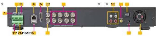
2 3 4 5 67 8 9 10 1 111214161315| ITEM | NAME | FUNCTION |
| 1 | PTZ | Connections for Pan-Tilt-Zoom speed dome cameras. Y = "^+" Z = "^- |
| 2 | K/B | Connector for a PTZ keyboard |
| 3 | ALARM IN | Connections for up to 8 external sensors |
| 4 | NET | Network (ethernet) port |
| 5 | VGA PORT | VGA output for 19" or larger monitor |
| 6 | VIDEO OUT | BNC connector for TV or monitor |
| 7 | VIDEO IN | BNC connectors for up to 8 cameras |
| 8 | AUDIO IN | 4 channels of audio input |
| 9 | AUDIO OUT | Audio output for amplified speaker |
| 10 | POWER Power On/Off | |
| 11 | +5V and GND | +5V and grounding |
| 12 | ALARM OUT 1 Channel relay output for external alarm | |
| 13 | USB PORT | For the USB mouse |
| 14 | SPOT OUT | Connect to another monitor as an auxiliary output channel. This monitor will only display video and will have no menu access. |
| 15 | DC IN | Power input for 12V DC power supply |
| 16 | FAN | Cooling fan exhaust port. This should not be blocked. |
QT518
FRONT PANEL
text_image
1 2 3 4 5 6 7 8 9 Q388 A CHANNEL CALL TO REBEACHING YOU 10 11 12 13 14 15 16 17 16ITEM NAME FUNCTION
| 1 | POWER (Behind flip-down panel) | Puts the DVR into standby mode or wakes it up from standby mode. |
| 2 | USB PORT(Behind flip-down panel) | Used for external USB backup devices. |
| 3 | NUMBER PAD Enter channel numbers. | |
| 4 | MENU Opens the Main Menu | |
| 5 | BACKUP Opens Backup Menu | |
| 6 DIRECTION Navigates through selections in menus | ||
| 7 RECORD | Begins manually recording on all channels | |
| 8 SEARCH | Enters Search Mode | |
| 9 | INDICATOR LIGHTS Shows status of the DVR Functions and the Hard Drive | |
| 10 VIEWING MODE | Change between 1, 4, and 8-screen viewing mode | |
| 11 10+ BUTTON | Input channels numbers above 10 by pushing this button followed by the second digit. | |
| 12 PTZ | Enter PTZ mode in live view | |
| 13 AUDIO | Turn audio on or off in live view if audio input devices are attached. | |
| 14 INFO | Displays system information | |
| 15 ENTER | Confirms selection in menus or input in fields | |
| 16 PLAYBACK CONTROLS | REW - RewindPLAY - Opens the Playback interface. Pauses or resumes playbackFF - Fast ForwardSTOP - Quits Playback modeAlso switches video output mode. | |
| 17 | CONTROL KNOB Outer ring navigates through menusInner knob increases or decreases speed of fast forward or rewind. | |
BACK PANEL
text_image
1 2 3 4 5 6 7 8 9 10 11 12 13 14 15 16 17 18 19ITEM NAME FUNCTION
| 1 VIDEO OUT BNC connector for TV or monitor | ||
| 2 HDMI HDMI video output | ||
| 3 VIDEO IN | BNC connectors for up to 8 cameras | |
| 4 | eSATA | Connection for external eSATA hard drive for backup |
| 5 LOOP OUT | Output each channel to a separate monitor | |
| 6 SPOT OUT | Connect to another monitor as an auxiliary output channel. This monitor will only display video and will have no menu access. | |
| 7 AUDIO OUT | Audio output for amplified speaker | |
| 8 MICROPHONE IN | Connect a microphone for two-way audio | |
| 9 VGA PORT | VGA output for 19" or larger monitor | |
| 10 | USB PORT | For the USB mouse |
| 11 | LAN | Network (ethernet) port |
| 12 | AUDIO IN | 8 channels of audio input |
| 13 | ALARM IN | Connect up to 8 external sensors |
| 14 | ALARM OUT | 4 Channel relay output for external alarms |
| 15 | PTZ | Connections for Pan-Tilt-Zoom speed dome cameras. Y = "+" Z = "-" |
| 16 | K/B | Connector for a PTZ keyboard |
| 17 | POWER SOCKET | Attachment point for power cord |
| 18 | POWER SWITCH | Use to turn on the DVR as well as to turn off after powering down from within the GUI |
| 19 | FAN | Cooling fan exhaust port. This should not be blocked. |
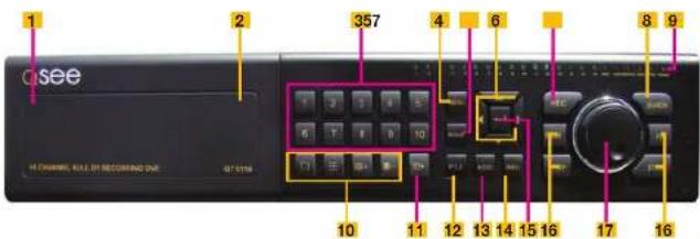
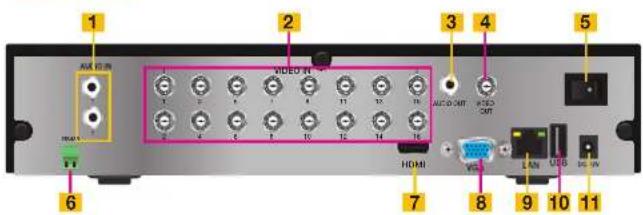
QT5116
FRONT PANEL
text_image
1 2 357 4 6 8 9 10 11 12 13 14 15 16 17 16 Q see H CHANNEL, RALL OR RECOMMING DUE Q7 01 16ITEM NAME FUNCTION
| 1 | POWER (Behind flip-down panel) | Puts the DVR into standby mode or wakes it up from standby mode. |
| 2 | USB PORT(Behind flip-down panel) | Used for external USB backup devices. |
| 3 | NUMBER PAD Enter channel numbers. | |
| 4 | MENU Opens the Main Menu | |
| 5 | BACKUP Opens Backup Menu | |
| 6 DIRECTION Navigates through selections in menus | ||
| 7 RECORD | Begins manually recording on all channels | |
| 8 SEARCH | Enters Search Mode | |
| 9 | INDICATOR LIGHTS Shows status of the DVR Functions and the Hard Drive | |
| 10 VIEWING MODE | Change between 1, 4, 8 and 16-screen viewing mode | |
| 11 10+ BUTTON | Input channels numbers above 10 by pushing this button followed by the second digit. | |
| 12 PTZ | Enter PTZ mode in live view | |
| 13 AUDIO | Turn audio on or off in live view if audio input devices are attached. | |
| 14 INFO | Displays system information | |
| 15 ENTER | Confirms selection in menus or input in fields | |
| 16 PLAYBACK CONTROLS | REW - RewindPLAY - Opens the Playback Interface. Pauses or resumes playbackFF - Fast ForwardSTOP - Quits Playback modeAlso switches video output mode. | |
| 17 | CONTROL KNOB Outer ring navigates through menusInner knob increases or decreases speed of fast forward or rewind. | |
BACK PANEL

text_image
1 2 3 4 5 6 7 8 9 10 11 12 13 HORU 14 15 16ITEM NAME FUNCTION
| 1 HDMI | HDMI video output | |
| 2 AUDIO OUT | Audio output for amplified speaker | |
| 3 AUDIO IN | 16 channels of audio input | |
| 4 | eSATA | Connection for external eSATA hard drive for backup |
| 5 | FAN | Cooling fan exhaust port. This should not be blocked. |
| 6 PTZ | Connections for Pan-Tilt-Zoom speed dome cameras. Y = "+" Z = "-" | |
| 7 K/B | Connector for a PTZ keyboard | |
| 8 ALARM IN | Connect up to 16 external sensors | |
| 9 LAN | Network (ethernet) port | |
| 10 | USB PORT | For the USB mouse |
| 11 | VGA PORT | VGA output for 19" or larger monitor |
| 12 | VIDEO OUT | BNC connector for TV or monitor |
| 13 | SPOT OUT | Connect to another monitor as an auxiliary output channel. This monitor will only display video and will have no menu access. |
| 14 | VIDEO IN | BNC connectors for up to 16 cameras |
| 15 | POWER SOCKET | Attachment point for power cord |
| 16 | POWER SWITCH | Use to turn on the DVR as well as to turn off after powering down from within the GUI |
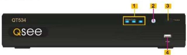
QT534
FRONT PANEL
text_image
QT534 Qsee 1 2 3 1 4ITEM NAME FUNCTION
| 1 INDICATOR LIGHTS | Shows the recording, network and power status of the DVR. |
| 2 INFRARED WINDOW | Receives signals from the remote control |
| 3 VIDEO MODE BUTTON | Press and hold 10 seconds (or until you hear a beep) to switch video output from the VGA port (default) to the BNC video out port. |
| 4 USB PORT Used for external USB backup devices. | |
REAR PANEL
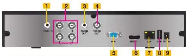
text_image
1 AUDIO IN 2 AUDIO OUT 3 VIDEO OUT 4 VIA 5 HDMI 6 LAN 7 USB 8 DC IV 9ITEM NAME FUNCTION
| 1 AUDIO IN 1 Channel of audio input |
| 2 VIDEO IN Video input from up to 4 cameras |
| 3 AUDIO OUT RCA audio output for amplified speaker |
| 4 VIDEO OUT BNC connector for TV or monitor |
| 5 VGA PORT VGA output for 19" or larger monitor |
| 6 HDMI HDMI video output |
| 7 LAN Network (ethernet) port |
| 8 USB PORT For the USB mouse |
| 9 DC IN Power input for 12V DC power supply |
QT536
FRONT PANEL
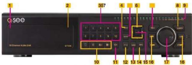
text_image
QSEE 16 Channel R284 GWR G734E 1 2 357 4 6 8 9 10 11 12 13 14 15 16 17 16ITEM NAME FUNCTION
| 1 | POWER (Behind flip-down panel) | Puts the DVR into standby mode or wakes it up from standby mode. |
| 2 | USB PORT(Behind flip-down panel) | Used for external USB backup devices. |
| 3 | NUMBER PAD Enter channel numbers. | |
| 4 | MENU Opens the Main Menu | |
| 5 | BACKUP Opens Backup Menu | |
| 6 DIRECTION Navigates through selections in menus | ||
| 7 RECORD | Begins manually recording on all channels | |
| 8 SEARCH | Enters Search Mode | |
| 9 | INDICATOR LIGHTS Shows status of the DVR Functions and the Hard Drive | |
| 10 VIEWING MODE | Change between 1, 4, 8 and 16-screen viewing mode | |
| 11 10+ BUTTON | Input channels numbers above 10 by pushing this button followed by the second digit. | |
| 12 PTZ | Enter PTZ mode in live view | |
| 13 AUDIO | Turn audio on or off in live view if audio input devices are attached. | |
| 14 INFO | Displays system information | |
| 15 ENTER | Confirms selection in menus or input in fields | |
| 16 PLAYBACK CONTROLS | REW - RewindPLAY - Opens the Playback Interface. Pauses or resumes playbackFF - Fast ForwardSTOP - Quits Playback modeAlso switches video output mode. | |
| 17 | CONTROL KNOB Outer ring navigates through menusInner knob increases or decreases speed of fast forward or rewind. | |
BACK PANEL

text_image
Labeled diagram of a computer rack showing ports, connectors, and power connections with numbered annotationsITEM NAME FUNCTION
| 1 VIDEO OUT | BNC connector for TV or monitor | |
| 2 VIDEO IN | BNC connectors for up to 16 cameras | |
| 3 LOOP OUT (2) | Output each channel to a separate monitor. Each port handles 8 channels. | |
| 4 SPOT OUT | Connect to another monitor as an auxiliary output channel. This monitor will only display video and will have no menu access. | |
| 5 AUDIO IN | 16 channels of audio input | |
| 6 AUDIO OUT | Audio output for amplified speaker | |
| 7 MICROPHONE IN | Connect a microphone for two-way audio | |
| 8 VGA PORT | VGA output for 19" or larger monitor | |
| 9 HDMI | HDMI video output | |
| 10 | USB PORT | For the USB mouse |
| 11 | LAN | Network (ethemet) port |
| 12 | eSATA (2) | Connection for external eSATA hard drive for backup |
| 13 | ALARM IN | Connect up to 16 external sensors |
| 14 | ALARM OUT | 4 Channel relay output for external alarms |
| 15 | PTZ | Connections for Pan-Tilt-Zoom speed dome cameras. Y = "+" Z = "-" |
| 16 | K/B | Connector for a PTZ keyboard |
| 17 | POWER SOCKET | Attachment point for power cord |
| 18 | POWER SWITCH | Use to turn on the DVR as well as to turn off after powering down from within the GUI |
| 19 | FAN | Cooling fan exhaust port. This should not be blocked. |
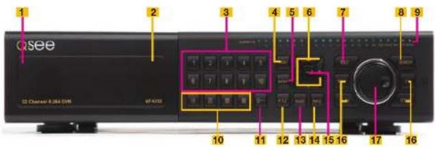
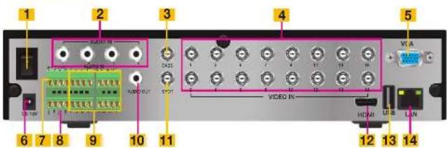
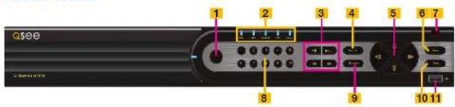
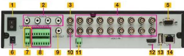
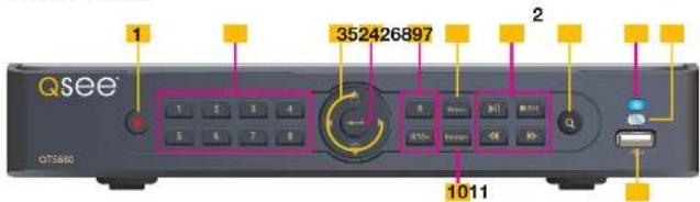
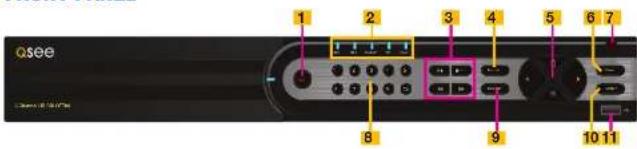
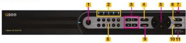
QT548 & QT578
FRONT PANEL

text_image
Qsee 1 2 3 4 5 6 7 8 10 9 11 12 13ITEM NAME FUNCTION
| 1 RECORD Manually begins recording | ||
| 2 LED | INDICATORS | Show status of power, HDD, record, etc. |
| 3 DIRECTION/MULTISCREEN | 1. Navigate through on-screen options2. Change screen display mode between 1, 4, and 9 channels | |
| 4 IR RECEIVER Receives signals from remote control | ||
| 5 ENTER Confirm selection | ||
| 6 PLAY/PAUSE Launches PLAYBACK window. | ||
| Starts or pauses video. | ||
| 7 REWIND Reverses video direction | ||
| 8 FAST FORWARD Changes playback speed | ||
| 9 STOP/ESC Quit PLAYBACK mode/Exit the current window or statusSwitch video output mode. (Press and hold 10 seconds) | ||
| 10-/BACKUP Decrease the value in SETUP/Enter backup mode in LIVEVIEW | ||
| 11+/MENU Increase the value in SETUP/Enter menu in LIVE VIEW | ||
| 12 SEARCH | Enters Search Mode | |
| 13 USB | USB port to connect USB flash or external hard drives toupdate firmware or back up recordings | |
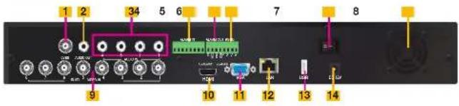
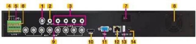
REAR PANEL
text_image
1 23 4 5 AUDIO IN AUDIO IN AUDIO IN VISA 6 78 9 10 11 12 13 14ITEM NAME FUNCTION
| 1 POWER SWITCH | Use to turn on the DVR as well as to turn off after powering down from within the GUI | |
| 2 AUDIO IN | 4 Channel audio input for cameras equipped with audio | |
| 3 CVBS (Video Out) | Video output for connecting to TV (BNC) or monitor | |
| 4 VIDEO IN | Video input from up to 8 cameras | |
| 5 VGA PORT | Video output for connecting to monitor | |
| 6 DC +12V Power input | ||
| 7 PTZ | PTZ camera connection ports | |
| 8 ALARM OUTPUT | Output for alarm | |
| 9 ALARM IN | Connect to up to 8 external sensors | |
| 10 AUDIO OUTPUT | Connection for audio output – connect to an amplified speaker | |
| 11 | SPOT | Connect to another monitor as an auxiliary output channel. This monitor will only display video and will have no menu access. |
| 12 HDMI | HDMI video output | |
| 13 USB PORT | Connect USB mouse | |
| 14 NET | Network (ethernet) port | |
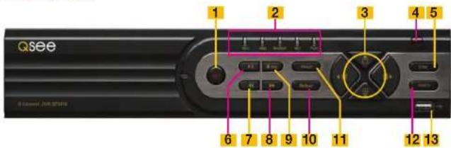
QT4760
FRONT PANEL

text_image
1 2 3 4 5 6 7 8 9 10 11 12 13ITEM NAME FUNCTION
| 1 RECORD Manually begins recording | ||
| 2 LED | INDICATORS | Show status of power, HDD, record, etc. |
| 3 DIRECTION/MULTISCREEN | 1. Navigate through on-screen options2. Change screen display mode between 1, 4, and 9 channels | |
| 4 IR RECEIVER Receives signals from remote control | ||
| 5 ENTER Confirm selection | ||
| 6 PLAY/PAUSE Launches PLAYBACK window. | ||
| Starts or pauses video. | ||
| 7 REWIND Reverses video direction | ||
| 8 FAST FORWARD Changes playback speed | ||
| 9 STOP/ESC Quit PLAYBACK mode/Exit the current window or statusSwitch video output mode. (Press and hold 10 seconds) | ||
| 10-/BACKUP Decrease the value in SETUP/Enter backup mode in LIVE VIEW | ||
| 11+/MENU Increase the value in SETUP/Enter menu in LIVE VIEW | ||
| 12 SEARCH | Enters Search Mode | |
| 13 USB | USB port to connect USB flash or external hard drives to update firmware or back up recordings | |
REAR PANEL
text_image
1 2 3 4 5 6 7 8 9 10 11ITEM NAME FUNCTION
| 1 AUDIO IN | 2-Channel audio input for cameras equipped with audio or microphones |
| 2 VIDEO IN | Video input from up to 16 cameras |
| 3 AUDIO OUT | Connection for audio output – connect to an amplified speaker |
| 4 VIDEO OUT | Video output for connecting to TV (BNC) or monitor |
| 5 POWER SWITCH | Use to turn on the DVR as well as to turn off after powering down from within the GUI |
| 6 PTZ | PTZ camera connection ports |
| 7 HDMI | HDMI video output |
| 8 VGA PORT | Video output for connecting to monitor |
| 9 NET | Network (ethernet) port |
| 10 USB PORT | Connect USB mouse |
| 11 DC +12V Power input |
QT5024
FRONT PANEL
text_image
1 2 3 4 5 6 7 8 9 Qsee 10 11 12 13 14 15 16 17 16ITEM NAME FUNCTION
| 1 | POWER (Behind flip-down panel) | Puts the DVR into standby mode or wakes it up from standby mode. |
| 2 | USB PORT(Behind flip-down panel) | Used for external USB backup devices. |
| 3 | NUMBER PAD Enter channel numbers. | |
| 4 | MENU Opens the Main Menu | |
| 5 | BACKUP Opens Backup Menu | |
| 6 DIRECTION Navigates through selections in menus | ||
| 7 | RECORD Begins manually recording on all channels | |
| 8 | SEARCH Enters Search Mode | |
| 9 | INDICATOR LIGHTS Shows status of the DVR Functions and the Hard Drive | |
| 10 | VIEWING MODE Change between 1, 4, 8 and 16-screen viewing mode | |
| 11 | 10+ BUTTON Input channels numbers above 10 by pushing this button followed by the second digit. | |
| 12 | PTZ Enter PTZ mode in live view | |
| 13 | AUDIO | Turn audio on or off in live view if audio input devices are attached. |
| 14 | INFO | Displays system information |
| 15 | ENTER | Confirms selection in menus or input in fields |
| 16 | PLAYBACK CONTROLS | REW - RewindPLAY - Opens the Playback interface. Pauses or resumes playbackFF - Fast ForwardSTOP - Quits Playback modeAlso switches video output mode. |
| 17 | CONTROL KNOB | Outer ring navigates through menusInner knob increases or decreases speed of fast forward or rewind. |
BACK PANEL
text_image
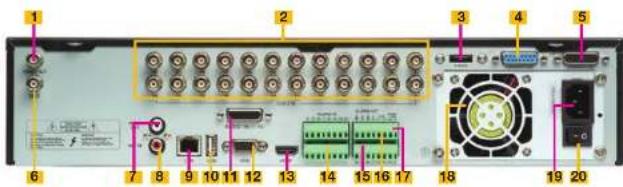
1 2 3 4 5 6 7 8 9 10 11 12 13 14 15 16 17 18 19 20ITEM NAME FUNCTION
| 1 VIDEO OUT | BNC connector for TV or monitor | |
| 2 VIDEO IN | BNC connectors for up to 24 cameras | |
| 3 | eSATA | Connection for external eSATA hard drive for backup |
| 4 LOOP OUT | Output each channel to a separate monitor. This port handles Channels 17-24. | |
| 5 LOOP OUT | Output each channel to a separate monitor. This port handles Channels 1-16. | |
| 6 SPOT OUT | Connect to another monitor as an auxiliary output channel. This monitor will only display video and will have no menu access. | |
| 7 AUDIO OUT | Audio output for amplified speaker | |
| 8 MICROPHONE IN | Connect a microphone for two-way audio | |
| 9 LAN | Network (ethernet) port | |
| 10 | USB PORT | For the USB mouse |
| 11 | AUDIO IN | 16 channels of audio input |
| 12 | VGA PORT | VGA output for 19" or larger monitor |
| 13 | HDMI | HDMI video output |
| 14 | ALARM IN | Connect up to 16 external sensors |
| 15 | ALARM OUT | 4 Channel relay output for external alarms |
| 16 | PTZ Connections for Pan-Tilt-Zoom speed dome cameras. Y = "+" Z = "-" | |
| 17 | K/B | Connector for a PTZ keyboard |
| 18 | FAN | Cooling fan exhaust port. This should not be blocked. |
| 19 | POWER SOCKET | Attachment point for power cord |
| 20 | POWER SWITCH | Use to turn on the DVR as well as to turn off after powering down from within the GUI |
QT5032
FRONT PANEL
text_image
1 2 3 4 5 6 7 8 9 Qsee 10 11 12 13 14 15 16 17 16ITEM NAME FUNCTION
| 1 | POWER (Behind flip-down panel) | Puts the DVR into standby mode or wakes it up from standby mode. |
| 2 | USB PORT(Behind flip-down panel) | Used for external USB backup devices. |
| 3 | NUMBER PAD Enter channel numbers. | |
| 4 | MENU Opens the Main Menu | |
| 5 | BACKUP Opens Backup Menu | |
| 6 DIRECTION Navigates through selections in menus | ||
| 7 | RECORD Begins manually recording on all channels | |
| 8 | SEARCH Enters Search Mode | |
| 9 | INDICATOR LIGHTS Shows status of the DVR Functions and the Hard Drive | |
| 10 | VIEWING MODE Change between 1, 4, 8 and 16-screen viewing mode | |
| 11 | 10+ BUTTON Input channels numbers above 10 by pushing this button followed by the second digit. | |
| 12 | PTZ Enter PTZ mode in live view | |
| 13 | AUDIO | Turn audio on or off in live view if audio input devices are attached. |
| 14 | INFO | Displays system information |
| 15 | ENTER | Confirms selection in menus or input in fields |
| 16 | PLAYBACK CONTROLS | REW - RewindPLAY - Opens the Playback interface. Pauses or resumes playbackFF - Fast ForwardSTOP - Quits Playback modeAlso switches video output mode. |
| 17 | CONTROL KNOB | Outer ring navigates through menusInner knob increases or decreases speed of fast forward or rewind. |
BACK PANEL
text_image
Labeled diagram of an electronic device rear panel showing ports, connectors, and power connectionsITEM NAME FUNCTION
| 1 VIDEO OUT | BNC connector for TV or monitor | |
| 2 VIDEO IN | BNC connectors for up to 32 cameras | |
| 3 | eSATA | Connection for external eSATA hard drive for backup |
| 4 LOOP OUT | Output each channel to a separate monitor. This port handles Channels 17-32. | |
| 5 LOOP OUT | Output each channel to a separate monitor. This port handles Channels 1-16. | |
| 6 SPOT OUT | Connect to another monitor as an auxiliary output channel. This monitor will only display video and will have no menu access. | |
| 7 AUDIO OUT | Audio output for amplified speaker | |
| 8 MICROPHONE IN | Connect a microphone for two-way audio | |
| 9 LAN | Network (ethernet) port | |
| 10 | USB PORT | For the USB mouse |
| 11 | AUDIO IN | 16 channels of audio input |
| 12 | VGA PORT | VGA output for 19" or larger monitor |
| 13 | HDMI | HDMI video output |
| 14 | ALARM IN | Connect up to 16 external sensors |
| 15 | ALARM OUT | 4 Channel relay output for external alarms |
| 16 | PTZ Connections for Pan-Tilt-Zoom speed dome cameras. Y = "+" Z = "-" | |
| 17 | K/B | Connector for a PTZ keyboard |
| 18 | FAN | Cooling fan exhaust port. This should not be blocked. |
| 19 | POWER SOCKET | Attachment point for power cord |
| 20 | POWER SWITCH | Use to turn on the DVR as well as to turn off after powering down from within the GUI |
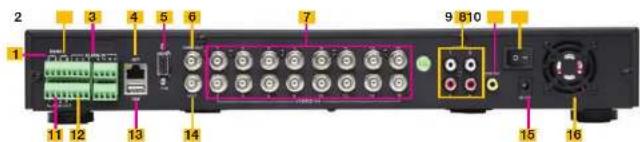
QT5132
FRONT PANEL
text_image
Qsee 1 2 3 4 5 6 7 8 9 10 11ITEM NAME FUNCTION
| 1 RECORD Manually begins recording | ||
| 2 LED | INDICATORS | Show status of power, HDD, record, etc. |
| 3 VIDEO | PLAYBACK CONTROLS | PLAY/PAUSE - Launches PLAYBACK window, Starts and pauses video.STOP/ESC - Quits PLAYBACK mode. Exits current windowSwitches video output mode (press and hold 10 seconds)REWIND - Reverses playback directionFAST FORWARD - Changes playback speed. |
| 4 MENU/+ Increase the value in SETUP/Enter menu in LIVE VIEW | ||
| 5 DIRECTION/MULTISCREEN | 1. Navigate through on-screen options2. Change screen display mode between 1, and 4 channels | |
| 6 ENTER Confirm selection | ||
| 7 IR RECEIVER Receives signals from remote control | ||
| 8 | NUMBER PAD Enter channel numbers. | |
| 9-/BACKUP Decrease the value in SETUP/Enter backup mode in LIVE VIEW | ||
| 10 SEARCH Enters Search Mode | ||
| 11 USB USB port to connect USB flash or external hard drives to update firmware or back up recordings | ||
BACK PANEL

text_image
1 2 3 4 5 6 7 8 9 10 11 12 13 14ITEM NAME FUNCTION
| 1 VIDEO IN | Video input from up to 32 cameras | |
| 2 BNC | OUT | Video output for connecting to TV (BNC) or monitor |
| 3 | AUDIO IN | 4-Channel audio input for cameras equipped with audio, or for separate microphones |
| 4 | AUDIO OUT | Connection for audio output – connect to an amplified speaker |
| 5 FAN | Cooling fan exhaust port. This should not be blocked. | |
| 6 ALARM IN | Input ports for 16 alarms. | |
| 7 ALARM OUT | One output port for external alarm | |
| 8 PTZ | RS485 BLOCK | Connections for Pan-Tilt-Zoom speed dome cameras, Y = "-" Z = "-" |
| 9 HDMI | HDMI video output | |
| 10 | VGA PORT | Video output for connecting to monitor at least 19" in size |
| 11 LAN | Network (ethemat) port | |
| 12 USB PORT | Connect USB mouse | |
| 13 DC | +12V Power input | |
| 14 | SPOT OUT | Connect to another monitor as an auxiliary output channel. This monitor will only display video and will have no menu access. |
QT5140 & QT5440
FRONT PANEL

text_image
QSee 352426897 1 2 1011 1 2 3 4 5 6 7 8 9 Multi Multi Multi Multi Multi Multi Multi Multi Multi Multi Multi Multi Multi Multi Multi Multi Multi Multi Multi Multi Multi Multi Multi Multi Multi Multi Multi Multi Multi Multi Multi Multi Multi Multi Multi Multi Multi Multi Multi Multi Multi Multi Multi Multi Multi Multi Multi Multi Multi Multi Mai Mai Mai Mai Mai Mai Mai Mai Mai| ITEM | NAME | FUNCTION |
| 1 | POWER | Power On/Off |
| 2 | NUMBER BUTTONS | Select individual channels and enter data where required |
| 3 | DIRECTION Navigates through selections in menus Selects viewing mode - Full Screen or 4-Channel Multi-Screen View | |
| 4 | ENTER | Confirm Selection |
| 5 | MENU | Opens the Main Menu Increases the value in Setup mode |
| 6 | PLAYBACK CONTROLS | In addition to normal DVR playback and record operation, the following have additional functions: RECORD Controls Focus in PTZ mode REVERSE Controls Speed in PTZ mode STOP/ESC Exits current interface or status Also switches video output mode. |
| 7 | SEARCH/ZOOM | Enter Search mode Controls Zoom function in PTZ mode |
| 8 | INDICATOR LIGHT | Shows power status of the DVR |
| 9 | INFRARED WINDOW | Receives signals from the remote control |
| 10 | BACKUP | Enter Backup mode Decreases the value in Setup mode |
| 11 | USB PORT | Used for external USB backup devices. |
REAR PANEL

text_image
1345678 9 10 AUDIO IN COLDEN IN AUDIO OUT VIDEO OUT VGA HDMI LAN USB REC 12V REC| ITEM | NAME | FUNCTION |
| 1 | AUDIO IN | 2 Channels of audio Input |
| 2 | VIDEO IN | Video input from up to 4 cameras |
| 3 | AUDIO OUT | Audio output for amplified speaker |
| 4 | VIDEO OUT | BNC connector for TV or monitor |
| 5 | VGA PORT | VGA output for 19" or larger monitor |
| 6 | HDMI | HDMI video output |
| 7 | LAN | Network (ethernet) port |
| 8 | USB PORT | Connect USB mouse |
| 9 | DC IN | Power input for 12V DC power supply |
| 10 | PTZ | Connections for Pan-Till-Zoom speed dome cameras. A = "1" B = "-" |
QT5516 & QT5616
FRONT PANEL
text_image
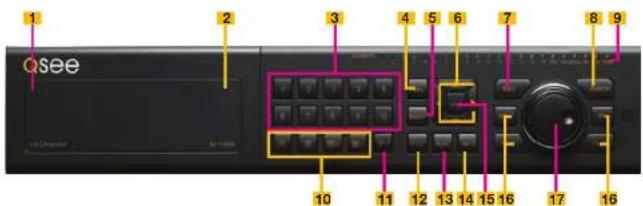
Qsee 1 2 3 4 5 6 7 8 9 10 11 12 13ITEM NAME FUNCTION
| 1 RECORD Manually begins recording | ||
| 2 LED | INDICATORS | Show status of power, HDD, record, etc. |
| 3 DIRECTION/MULTISCREEN | 1. Navigate through on-screen options2. Change screen display mode between 1, 4, and 9 channels | |
| 4 IR RECEIVER Receives signals from remote control | ||
| 5 ENTER Confirm selection | ||
| 6 PLAY/PAUSE Launches PLAYBACK window Grants or pauses video. | ||
| 7 REWIND Reverses video direction | ||
| 8 FAST FORWARD Changes playback speed | ||
| 9 STOP/ESC Quit PLAYBACK mode/Exit the current window or statusSwitch video output mode. (Press and hold 10 seconds) | ||
| 10-/BACKUP Decrease the value in SETUP/Enter backup mode in LIVE VIEW | ||
| 11+/MENU Increase the value in SETUP/Enter menu in LIVE VIEW | ||
| 12 SEARCH Enters Search Mode | ||
| 13 USB | USB port to connect USB flash or external hard drives to update firmware or back up recordings | |
REAR PANEL
text_image
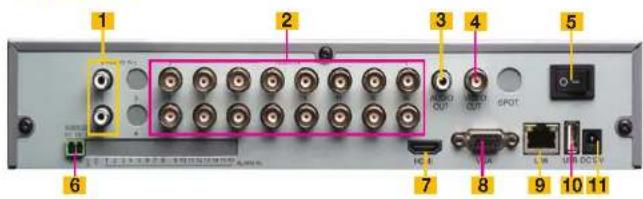
1 2 3 4 5 6 7 8 9 10 11 VIDEO IN 12 13 14ITEM NAME FUNCTION
| 1 POWER SWITCH | Use to turn on the DVR as well as to turn off after powering down from within the GUI | ||
| 2 AUDIO IN | 4-Channel audio input for cameras equipped with audio or microphones | ||
| 3 VIDEO OUT | Video output for connecting to TV (BNC) or monitor | ||
| 4 VIDEO IN | Video input from up to 16 cameras | ||
| 5 VGA PORT | Video output for connecting to monitor | ||
| 6 DC +12V Power input | |||
| 7 ALARM OUTPUT | Output for alarm | ||
| 8 ALARM IN | Connect to up to 16 external sensors | ||
| 9 | AUDIO OUT | Connection for audio output – connect to an amplified speaker | |
| 10 | SPOT | Connect to another monitor as an auxiliary output channel. This monitor will only display video and will have no menu access. | |
| 11 PTZ | PTZ camera connection ports | ||
| 12 HDMI | HDMI video output | ||
| 13 USB PORT | Connect USB mouse | ||
| 14 NET | Network (ethernet) port | ||
QT5680 & QT5682
FRONT PANEL
text_image
QSee 352426897 1 2 1011 OT560| ITEM | NAME | FUNCTION |
| 1 | RECORD | Manually begins recording |
| 2 | NUMBER BUTTONS | Select individual channels and enter data where required |
| 3 | DIRECTION Navigates through selections in menus Selects viewing mode - Full Screen or 4-Channel Multi-Screen View | |
| 4 | ENTER | Confirm Selection |
| 5 | MENU | Opens the Main Menu Increases the value in Setup mode |
| 6 | PLAYBACK CONTROLS | In addition to normal DVR playback and record operation, the following have additional functions: RECORD Controls Focus in PTZ mode REVERSE Controls Speed in PTZ mode STOP/ESC Exits current interface or status Also switches video output mode. |
| 7 | SEARCH/ZOOM | Enter Search mode Controls Zoom function in PTZ mode |
| 8 | INDICATOR LIGHT | Shows power status of the DVR |
| 9 | INFRARED WINDOW | Receives signals from the remote control |
| 10 | BACKUP | Enter Backup mode Decreases the value in Setup mode |
| 11 | USB PORT | Used for external USB backup devices. |
REAR PANEL
text_image
1345678 9 10 ADDN VISA AUDIO OUT VISA HDMI LAN USB R USB| ITEM | NAME | FUNCTION |
| 1 | AUDIO IN | 2 Channels of audio input |
| 2 | VIDEO IN | Video input from up to 8 cameras |
| 3 | AUDIO OUT | Audio output for amplified speaker |
| 4 | VIDEO OUT | BNC connector for TV or monitor |
| 5 | VGA PORT | VGA output for 19" or larger monitor |
| 6 | HDMI | HDMI video output |
| 7 | LAN | Network (ethernet) port |
| 8 | USB PORT | Connect USB mouse |
| 9 | DC IN | Power input for 12V DC power supply |
| 10 | PTZ | Connections for Pan-Tilt-Zoom speed dome cameras. A = "+" B = "-" |
QT5716
FRONT PANEL

text_image
Qsee 1 2 3 4 5 6 7 8 9 10 11 12 13ITEM NAME FUNCTION
| 1 RECORD Manually begins recording | ||
| 2 LED | INDICATORS | Show status of power, HDD, record, etc. |
| 3 DIRECTION/MULTISCREEN | 1. Navigate through on-screen options2. Change screen display mode between 1, 4, 9 and 16 channels | |
| 4 IR RECEIVER Receives signals from remote control | ||
| 5 ENTER Confirm selection | ||
| 6 PLAY/PAUSE Launches PLAYBACK window.Starts or pauses video. | ||
| 7 REWIND Reverses video direction | ||
| 8 FAST FORWARD Changes playback speed | ||
| 9 STOP/ESC Quit PLAYBACK mode/Exit the current window or statusSwitch video output mode. (Press and hold 10 seconds) | ||
| 10-/BACKUP Decrease the value in SETUP/Enter backup mode in LIVE VIEW | ||
| 11+/MENU Increase the value in SETUP/Enter menu in LIVE VIEW | ||
| 12 SEARCH Enters Search Mode | ||
| 13 USB | USB port to connect USB flash or external hard drives to update firmware or back up recordings | |
REAR PANEL
text_image
1 2 3 4 5 6 7 8 9 10 11 VIDEO MT VIDEO MT HDMI VSS LAN USB USBITEM NAME FUNCTION
| 1 AUDIO IN | 2-Channel audio input for cameras equipped with audio | |
| 2 VIDEO IN | Video input from up to 16 cameras | |
| 3 AUDIO OUTPUT | Connection for audio output – connect to an amplified speaker | |
| 4 VIDEO OUT | Video output for connecting to TV (BNC) or monitor | |
| 5 POWER SWITCH | Use to turn on the DVR as well as to turn off after powering down from within the GUI | |
| 6 RS-485 (PTZ) | PTZ camera connection ports | |
| 7 HDMI | HDMI video output | |
| 8 VGA PORT | Video output for connecting to monitor | |
| 9 NET | Network (ethernet) port | |
| 10 USB PORT | Connect USB mouse | |
| 11 DC +12V Power input | ||
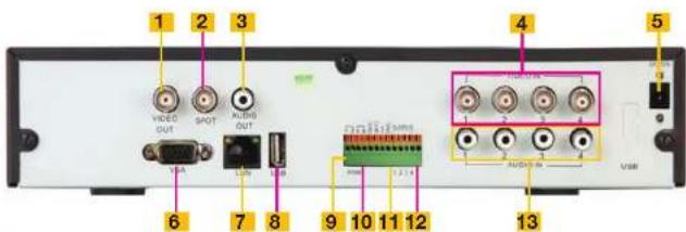
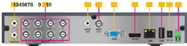
QT704 QT714
FRONT PANEL
text_image
Qsee 1 2 3 4 5 6 7 8 9 10 11ITEM NAME FUNCTION
| 1 RECORD Manually begins recording | ||
| 2 LED | INDICATORS | Show status of power, HDD, record, etc. |
| 3 VIDEO | PLAYBACK CONTROLS | PLAY/PAUSE - Launches PLAYBACK window, Starts and pauses video.STOP/ESC - Quits PLAYBACK mode, Exits current windowSwitches video output mode (press and hold 10 seconds)REWIND - Reverses playback directionFAST FORWARD - Changes playback speed. |
| 4 MENU/+ Increase the value in SETUP/Enter menu in LIVE VIEW | ||
| 5 DIRECTION/MULTISCREEN | 1. Navigate through on-screen options2. Change screen display mode between 1, and 4 channels | |
| 6 ENTER Confirm selection | ||
| 7 IR RECEIVER Receives signals from remote control | ||
| 8 | NUMBER PAD Enter channel numbers. | |
| 9-/BACKUP Decrease the value in SETUP/Enter backup mode in LIVEVIEW | ||
| 10 SEARCH Enters Search Mode | ||
| 11 USB USB port to connect USB flash or external hard drives toupdate firmware or back up recordings | ||
REAR PANEL

text_image
1 2 3 4 5 6 7 8 9 10 11 12ITEM NAME FUNCTION
| 1 PTZ & ALARMINTERFACE | Connections for Pan-Tilt-Zoom speed dome cameras. Y = "+" Z = "-"Input ports for 4 alarms. One output port for external alarm | |
| 2 HDMI | HDMI video output | |
| 3 USB | PORT | Connect USB mouse |
| 4 | VGA PORT | Video output for connecting to monitor at least 19" in size |
| 5 CVBS (Video Out) | Video output for connecting to TV (BNC) or monitor | |
| 6 AUDIO IN | 4-Channel audio input for cameras equipped with audio | |
| 7 FAN | Cooling fan exhaust port. This should not be blocked. | |
| 8 LAN | Network (ethernet) port | |
| 9 AUDIO OUTPUT | Connection for audio output - connect to an amplified speaker | |
| 10 VIDEO IN | Video input from up to 4 HD SDI cameras | |
| 11 DC | +12V Power input | |
| 12 POWER SWITCH | Use to turn on the DVR as well as to turn off after powering down from within the GUI | |
QT718
FRONT PANEL
text_image
Qsee 1 2 3 4 5 6 7 8 9 10 11ITEM NAME FUNCTION
| 1 RECORD Manually begins recording | ||
| 2 LED | INDICATORS | Show status of power, HDD, record, etc. |
| 3 VIDEO PLAYBACK CONTROLS | PLAY/PAUSE - Launches PLAYBACK window, Starts and pauses video.STOP/ESC - Quits PLAYBACK mode. Exits current window Switches video output mode (press and hold 10 seconds) REWIND - Reverses playback direction FAST FORWARD - Changes playback speed. | |
| 4 MENU/+ Increase the value in SETUP/Enter menu in LIVE VIEW | ||
| 5 DIRECTION/MULTISCREEN | 1. Navigate through on-screen options2. Change screen display mode between 1, and 4 channels | |
| 6 ENTER Confirm selection | ||
| 7 IR RECEIVER Receives signals from remote control | ||
| 8 | NUMBER PAD Enter channel numbers. | |
| 9-/BACKUP Decrease the value in SETUP/Enter backup mode in LIVE VIEW | ||
| 10 SEARCH Enters Search Mode | ||
| 11 USB USB port to connect USB flash or external hard drives to update firmware or back up recordings | ||
REAR PANEL
text_image
1 2 34 5 6 7 8 9 10 11 12 13 14ITEM NAME FUNCTION
| 1 CVBS (Video Out) | Video output for connecting to TV (BNC) or monitor | |
| 2 AUDIO OUTPUT | Connection for audio output – connect to an amplified speaker | |
| 3 AUDIO IN | 4-Channel audio input for cameras equipped with audio | |
| 4 ALARM IN | Input ports for 8 alarms. | |
| 5 ALARM OUT | One output port for external alarm | |
| 6 PTZ RS485 BLOCK | Connections for Pan-Tilt-Zoom speed dome cameras, Y = "-" Z = "-" | |
| 7 POWER SWITCH | Use to turn on the DVR as well as to turn off after powering down from within the GUI | |
| 8 FAN | Cooling fan exhaust port. This should not be blocked. | |
| 9 VIDEO IN | Video input from up to 8 HD SDI cameras | |
| 10 HDMI | HDMI video output | |
| 11 | VGA PORT | Video output for connecting to monitor at least 19" in size |
| 12 LAN | Network (ethemat) port | |
| 13 USB PORT | Connect USB mouse | |
| 14 DC +12V Power Input | ||
Later production QT718s have the ports slightly rearranged (below).
text_image
4 5 6 1 2 3 7 8 9 10 11 12 13 14QT724
FRONT PANEL
text_image
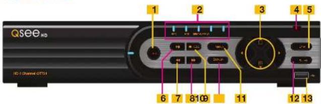
Qsee HD HD 2 Channel OTTS1 1 2 3 4 5 6 7 8 9 10 11 12 13ITEM NAME FUNCTION
| 1 RECORD Manually begins recording | ||
| 2 LED | INDICATORS | Show status of power, HDD, record, etc. |
| 3 DIRECTION/MULTISCREEN | 1. Navigate through on-screen options2. Change screen display mode between 1, and 4 channels | |
| 4 IR RECEIVER Receives signals from remote control | ||
| 5 ENTER Confirm selection | ||
| 6 PLAY/PAUSE Launches | PLAYBACK window Grants or pauses video. | |
| 7 REWIND Reverses video direction | ||
| 8 FAST FORWARD Changes playback speed | ||
| 9 STOP/ESC Quit PLAYBACK mode/Exit the current window or statusSwitch video output mode. (Press and hold 10 seconds) | ||
| 10-/BACKUP Decrease the value in SETUP/Enter backup mode in LIVE VIEW | ||
| 11+/MENU Increase the value in SETUP/Enter menu in LIVE VIEW | ||
| 12 SEARCH | Enters Search Mode | |
| 13 USB | USB port to connect USB flash or external hard drives to update firmware or back up recordings | |
REAR PANEL

text_image
1 2 3 4 5 HUAAN HUAAN HUAAN HUAAN HUAAN HUAAN HUAAN HUAAN HUAAN HUAAN HUAAN HUAAN HUAAN HUAAN HUAAN HUAAN HUAAN HUAAN HUAAN HUAAN HUAAN HUAAN HUAAN HUAAN HUAAN HUAAn HUAAn HUAAn HUAAn HUAAn HUAAn HUAAn HUAAn HUAAn HUAAn HUAAn HUAAn HUAAn HUAAn HUAAn HUAAn HUAAn HUAAn HUAAn HUAAn HUAAn HUAAn HUAAn HUAAn HUAAn HUAan HuaAn HuaAn HuaAn HuaAn HuaAn HuaAn HuaAn HuaAn HuaAn HuaAn HuaAn HuaAn HuaAn HuaAn HuaAn HuaAn HuaAn HuaAn HuaAn HuaAn HuaAn HuaAn HuaAn HuaAn HuaAnITEM NAME FUNCTION
| 1 | ALARM | Input for 4 external sensors and output for 1 external alarm |
| 2 RS-485 (PTZ) | PTZ camera connection ports | |
| 3 VIDEO OUT | Video output for connecting to TV (BNC) or monitor | |
| 4 AUDIO OUTPUT | Connection for audio output – connect to an amplified speaker | |
| 5 AUDIO IN | 4 audio input channels for cameras equipped with audio | |
| 6 VIDEO IN | Video input from up to 4 cameras | |
| 7 HDMI | HDMI video output | |
| 8 VGA PORT | Video output for connecting to monitor | |
| 9 NET | Network (ethernet) port | |
| 10 USB PORT | Connect USB mouse | |
| 11 DC +12V Power input | ||
QT728
FRONT PANEL

text_image
Qsee HD 1 2 3 4 5 6 7 8 9 10 11 12 13 HD 2 Channel GPTSLITEM NAME FUNCTION
| 1 RECORD Manually begins recording | ||
| 2 LED | INDICATORS | Show status of power, HDD, record, etc. |
| 3 DIRECTION/MULTISCREEN | 1. Navigate through on-screen options2. Change screen display mode between 1, 4, 9 and 16 channels | |
| 4 IR RECEIVER Receives signals from remote control | ||
| 5 ENTER Confirm selection | ||
| 6 PLAY/PAUSE Launches PLAYBACK window. | ||
| Starts or pauses video. | ||
| 7 REWIND Reverses video direction | ||
| 8 FAST FORWARD Changes playback speed | ||
| 9 STOP/ESC Quit PLAYBACK mode/Exit the current window or statusSwitch video output mode. (Press and hold 10 seconds) | ||
| 10-/BACKUP Decrease the value in SETUP/Enter backup mode in LIVE VIEW | ||
| 11+/MENU Increase the value in SETUP/Enter menu in LIVE VIEW | ||
| 12 SEARCH Enters Search Mode | ||
| 13 USB | USB port to connect USB flash or external hard drives toupdate firmware or back up recordings | |
REAR PANEL
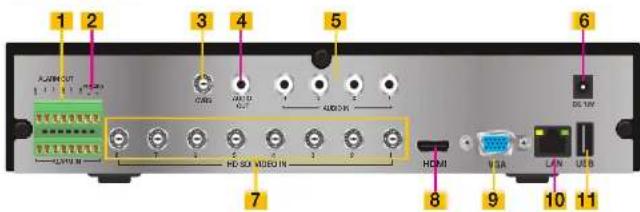
text_image
1 2 3 4 5 6 A:J894-OUT 1 1 1 1 1 C:GRL V:U D I:U D H:SO V:DO IN A:DO IN DG:UV 7 HOMI 8 9 10 11 V:SA L:W USBITEM NAME FUNCTION
| 1 | ALARM | Input for 8 external sensors and output for 1 external alarm |
| 2 RS-485 (PTZ) | PTZ camera connection ports | |
| 3 VIDEO OUT | Video output for connecting to TV (BNC) or monitor | |
| 4 AUDIO OUTPUT | Connection for audio output – connect to an amplified speaker | |
| 5 AUDIO IN | 8 audio input channels for cameras equipped with audio | |
| 6 DC +12V Power Input | ||
| 7 VIDEO IN | Video input from up to 8 cameras | |
| 8 HDMI | HDMI video output | |
| 9 VGA PORT | Video output for connecting to monitor | |
| 10 NET | Network (ethernet) port | |
| 11 USB PORT | Connect USB mouse | |
QT7116
FRONT PANEL
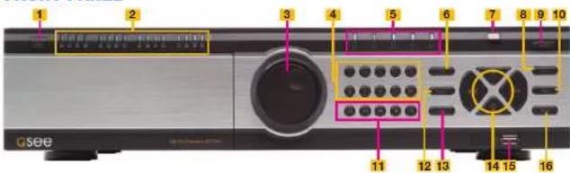
text_image
1 2 3 4 5 6 7 8 9 10 11 12 13 14 15 16 GseeITEM NAME FUNCTION
| 1 SHUT DOWN Press and hold to begin the shutdown process. the hard drive(s) will spin down and the DVR will display a message letting you know when it is safe to turn off the power using the switch on the rear panel (Item #16 on the next page). | |
| 2 CHANNEL LED INDICATORS | Shows the connection status of each camera. |
| 3 VIDEO PLAYBACK KNOB | For use in Video Playback mode. Allows fine adjustment of video playback speed. |
| 4 NUMBERS For selecting channels. Use the 0/10+ button for selecting channels 10-16 | |
| 5 LED INDICATORS | Show status of power, hard drive, record, etc. |
| 6 INFO Opens the Information menu | |
| 7 IR RECEIVER Receives signals from remote control | |
| 8 ENTER Confirm selection | |
| 9 RECORD Begins manual recording on all channels | |
| 10 MENU Opens MAIN MENU | |
| 11 VIDEO PLAYBACK CONTROLS | For use in Video Playback mode. Pressing the magnifying glass icon enters the Video Search mode. |
| 12 AUDIO/+ Turns audio on or off. Increase the value in SETUP | |
| 13 PTZ/- Opens PTZ control menu. Decreases the value in SETUP | |
| 14 DIRECTION/ MULTISCREEN | 1. Navigate through on-screen options2. Change screen display mode between 1, 4, 9 and 16 channels |
| 15 USB USB port to connect USB flash or external hard drives to update firmware or back up recordings | |
| 16 BACKUP Opens BACKUP window. | |
REAR PANEL
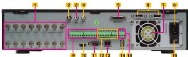
text_image
Labeled diagram of an electronic device rear panel showing ports, connectors, and internal components with numbered labelsITEM NAME
FUNCTION
| 1 VIDEO IN | Video input from up to 16 HD SDI cameras | |
| 2 CVBS (Video Out) | Video output for connecting to TV (BNC) or monitor | |
| 3 AUDIO OUTPUT | Connection for audio output – connect to an amplified speaker | |
| 4 MIC IN | RCA connection for using microphone. Requires speaker(s) located with camera(s). | |
| 5 | AUDIO IN | 16 channel audio input for cameras equipped with audio. Dongle is located in accessory box. |
| 6 | ESATA | Ports for connecting two external SATA hard drives for backup. |
| 7 | FAN | Cooling fan exhaust port. This should not be blocked. |
| 8 DC +12V | Power input | |
| 9 ALARM IN | Input ports for 16 alarms. | |
| 10 HDMI | HDMI video output | |
| 11 | VGA PORT | Video output for connecting to monitor at least 19" in size |
| 12 ALARM OUT | Four output ports for external alarms | |
| 13 LAN | Network (ethernet) port | |
| 14 USB PORT | Connect USB mouse | |
| 15 PTZ RS485 BLOCK | Connections for Pan-Tilt-Zoom speed dome cameras. Y = "+" Z = "-" | |
| 16 POWER SWITCH | Use to turn on the DVR as well as to turn off after powering down from within the GUI | |
In addition to the buttons on the front of the DVR, your system can be controlled through the USB mouse and the remote control. We have found that the majority of our customers prefer to operate their DVRs using the USB mouse because of its ease of use and flexibility and our manual is set up with this in mind.
2.2 MOUSE
The mouse is the default tool for navigating through the menus. Specific instructions for its use within a function appear in the appropriate sections of the manual, but a basic overview is below:
In Live View:
Double-click the left button on any camera view in split-screen mode to bring it to full-screen display.
Double-click again to return to split-screen mode.
Right-click to show the control bar at the bottom of the screen.
Right-clicking again will hide the control bar.
In Setup:
Left-click to make a selection. Right-click to cancel setup or return to previous screen.
To Input Values:

natural_image
Illustration of a computer mouse with a black body and white bezel, no text or symbols present.PICTURE 2-1
Move the cursor to a blank field and click. A virtual keyboard will appear which supports numbers, letters and symbols. The Shift function will access symbols in addition to upper case letters.
Certain values, such as time settings, can be changed using the mouse wheel.

text_image
1 2 3 4 5 6 7 8 9 0 Backspace q w e r t y u i o p [ ] \ a s d f g h j k l ; ' Enter Shift z x c v b n m . / . Esc - =PICTURE 2-2
2.3 REMOTE CONTROL
The remote control allows you to perform most of the day-to-day functions from a convenient distance. It functions as a typical remote control with additional buttons allowing you to navigate through menus and control functions. We recommend that you configure your DVR using the mouse controls, reserving the remote control for operations such as live viewing, file search and playback.
There are three models. All use two AAA-sized batteries. If the remote's performance degrades, check the batteries as well as that the IR receiver window on the DVR is unobstructed.
Item Button Function
| 1 POWER | Soft power down switch. Use this before unplugging the DVR | |
| 2 INFO | Get Information about the DVR such as HDD space and firmware version | |
| 3 REC | Begin recording | |
| 4 Numbers | Input numbers in fields or select camera | |
| 5 Multi Screen | Choose multi screen display mode | |
| 6 MENU | Opens MENU window | |
| 7 SEARCH | Enter SEARCH mode | |
| 8 Directional | Move cursor in set up or control PTZ camera | |
| 9 ENTER | Confirm choice or settings | |
| 10 SET 1/ | Increase or decrease value in SETUP mode | |
| 11 Playback | Controls playback functions, including stop, single-frame, fast forward, etc. | |
| 12 AUDIO | Enable audio input in live mode | |
| 13 SEQ | Returns to auto dwell display sequence | |
| 14 BACKUP | Enters BACKUP menu | |
| 15 | PTZ Controls | Controls PTZ camera including zoom, focus, ris and speed |

text_image
123 PUMBER INFO RPG 5 6 7 8 9 G/10 11 12 13 14 15 16 1X1 2X2 3X3 4X4 MENU SEARCH ENTER SR SF - SET + AUDIO 10 11 12 13 14 15PICTURE 2-3

NOTE! The remote that shipped with your DVR will be compatible with that model. It may not be compatible with other models of DVRs, even those from the same series. Your remote may contain buttons for features not available on your DVR.
| 1 | 2 | ||
| 1 2 3 | |||
| 4 5 6 | 3 | ||
| 7 8 9 | 4 | ||
| -/- 0 Fn1 | |||
| 5 | Multi Next SEQ | 7 | |
| 6 | SPOTAudio | 9 | |
| 8 | |||
| 10 | ENTER | 11 | |
| 12 | ExitMenu | 13 | |
| IRIS+ | |||
| 14 | + | + | |
| Focus | P.T.Z. Zoom | ||
| — | IRIS- — | ||
| 15 | Preset Cruise Wiper Light | 17 | |
| 16 | 18 | ||
| 19 | Track Clear Fn 2 INFO | 21 | |
| 20 | 22 | ||
| Snap Search | 24 | ||
| 25 | |||
| 23 | Cut Backup | 26 | |
| Zoom PIP | 27 | ||
| 28 | |||
| 29 |
| 1 | POWER | Soft power down switch. Use this before unplugging the DVR |
| 2 | REC | Begin recording |
| 3 | Numbers | Input numbers in fields or select camera |
| 4 | Fn1 | Not functional at this time |
| 5 | Multi-Screen | Choose multi-screen display mode |
| 6 | Next | Switch to next live view group |
| 7 | SEQ | Switch to sequential channel display |
| 8 | Audio | Enables Audio in Live View Mode |
| 9 | Spot | Change video display mode |
| 10 | Enter | Confirms choice |
| 11 | Directional Controls | Move cursorControl PTZ direction in PTZ mode |
| 12 | Menu | Open Main menu |
| 13 | Exit | Exits menu or interface |
| 14 | PTZ Controls | Controls PTZ camera including zoom, focus, iris and speed |
| 15 | Preset | Opens PTZ preset settings |
| 16 | Cruise | Opens PTZ cruise settings |
| 17 | Light | Turns on PTZ cameras light |
| 18 | Wiper | Turns on PTZ camera wiper |
| 19 | Track | Opens PTZ track settings |
| 20 | Clear | Returns to previous menu/ interface |
| 21 | Info | Opens DVR Info menu |
| 22 | Fn2 | Not functional at this time |
| 23 | Playback Controls | Play/Pause, Stop, Fast Forward, Rewind, Single Frame Forward/Backward |
| 24 | Search | Opens up video search window |
| 25 | Snap | Takes still image snapshot of active live view window |
| 26 | Backup | Opens Backup menu |
| 27 | Cut | Select start/end points to create a shorter video segment from a video being played back. |
| 28 | PIP | Picture-in-Picture mode |
| 29 | Zoom | Activates digital zoom |
Press the PTZ button to enter the PTZ control panel. Choose a channel and then press the PTZ button to close the panel. Wiper and light functions only function if PTZ camera is so equipped.

text_image
1 2 3 4 REC Search MENU Exit ENTER 5 6 7 8 9 ZoomM PIP II I NextSEQMulti INFO 10121113PICTURE 2-5
| # Button Function | ||
| 1 Menu | Open Main menu | |
| 2 REC | Begin recording | |
| 3 Search | Opens up video search window | |
| 4 Exit | Exits menu or interface | |
| 5 | Direc-tional Controls | Move cursorControl PTZ direction in PTZ mode |
| 6 Enter | Confirms choice | |
| 7 PiP | Picture-in-Picture mode | |
| 8 Zoom | Activates digital zoom | |
| 9 | Play-back Controls | Play/Pause, Stop, Fast Forward, Rewind, Single Frame Forward/Backward |
| 10 | Multi-Screen | Choose multi-screen display mode |
| 11 Next | Switch to next live view group | |
| 12 Info | Opens DVR Info menu | |
| 13 SEQ | Switch to sequential channel display | |
2.4 VIDEO DISPLAY
QT-Series DVRs can use a television or a 19" or larger monitor as a main video display. Certain models also provide the option of using a high definition display, such as an HDTV. A video display is not needed for day to day use of your DVR if you are only monitoring it remotely via a mobile device or using a computer, but one is needed for initial setup. It should also be noted that, at present, it is not possible to change settings on the DVR itself using the QT View mobile remote viewing apps and certain settings cannot be changed using the remote monitoring software on the computer.
CONNECTING A VIDEO DISPLAY
Instructions on connecting a desired video display are included in the Quick Start Poster that came with your system but are included here for your convenience.
VGA Monitor
Using a standard VGA monitor - the type used with most computers - with your DVR is the preferred method and the DVR is configured with this in mind. Due to resolution restrictions, you must use a monitor that has at least a 19° diagonal display. This information is typically found on the back of the monitor if you are uncertain.
STEP 1. Plug a VGA cable into the port marked "VGA" on the back of the DVR.
STEP 2. Plug the other end of the VGA cable into the similar port on the back of the monitor.
STEP 3. Plug the monitor's power cable into the surge protector.
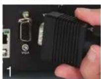
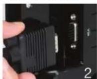

PICTURE 2-6
High Definition Television
Some QT-Series DVRs include an HDMI video out port allowing you to use a high definition television or other display that has an HDMI video input.
STEP 1. Plug an HDMI cable into the "HDMI" port on the back of the DVR.
STEP 2. Plug the other end into the "HDMI" port on the television.
STEP 3. Plug the television's power cable into a surge protector.

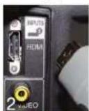
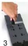
PICTURE 2-7
Changing Display Resolution
You can adjust the DVR to optimize its output to best match the capabilities of your monitor or HD display through the following steps:
STEP 1. Open the Basic window in the Setup window which is located in the Main Menu.
STEP 2. Click on the System tab.
STEP 3. Use the Video Output pull-down to select your desired resolution.
STEP 4. Click on Apply to save your settings and then click Exit.
STEP 5. Your system will restart. You will have to re-log in afterwards.
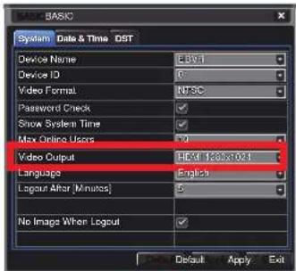
text_image
BASIC System Data & Time DST Device Name Edit Device ID 0 Video Format NTSC Password Check ✓ Show System Time ✓ Max Online Users 9 Video Output Hx1 1365x1021 Language English Layout After [Minutes] 5 No Image When Layout ✓ Default Apply ExitPICTURE 2-8
Television
A third option for a video display is any television with an RCA video input. The DVR's Video Out port uses a BNC (British Naval Connector) type for coaxial cable. Depending on model, your DVR may include a BNC-to-PCA cable or adapter. The latter converts the BNC jack to an RCA port allowing you to connect the DVR to the television using a readily available RCA cable. If you use a television as your video display, you will need to switch the DVR to use that as a primary output by following Step 4, below:

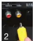
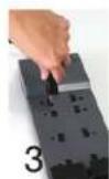

PICTURE 2-9
STEP 1. Connect a BNC-to-RCA cable to the "Video Out" port on the back of the DVR.
STEP 2. Plug the RCA end into the "Video In" port on the television.
STEP 3. Plug the television's power cable into a surge protector.
STEP 4. Press and hold the STOP, STOP/ESC, EXIT, ■/ESC or VGA/TV (depending on model) button on the front of the DVR for 10 seconds or until you hear a beep to indicate that the video mode has been changed.
'MISSING' MENU
If you are able to see your camera's video feeds, but you are unable to see your mouse cursor or menu, the most likely cause is that your video mode has been changed. In this case, you need to follow Step 4, above and you should see the cursor and/or menu after the beep.
MULTIPLE MONITORS AND SPOT OUT
Some DVRs include a Spot Out BNC port on their back panel. This allows you to connect a second video display that will show selected channels in sequence, but will not display the menu and therefore cannot be used to control the DVR. This is covered in Section 4.2 Live Configuration. Some users will want to take advantage of the unused video display outputs (ie; using the BNC Video Out port when the VGA port is being used for the main display. This "extra" display will mirror whatever is shown on the primary display but it will not show the menu or cursor. It is not possible to divide channels across two displays.
Loop Out
Some of our larger DVRs, such as the QT518 and QT536 include one or more ports marked Loop Out. These ports work with the included dongle(s) that split the video signal allowing the user to connect one monitor per channel. In this case, the menu will not be displayed on any of these additional monitors.
2.5 CAMERAS
CONNECTING CAMERAS
Your DVR uses BNC connectors and ports to ensure quick and secure connections for your cameras' video cables. While both conventional analog and digital SDI (Serial Digital Interface) high definition cameras use this interface, they cannot be connected to a port intended for the other type because of incompatible signals. It is therefore important to ensure that you are attempting to connect to the proper port.
STEP 1. Connect the BNC and power leads on the camera to the matching connectors on the power and video cable.
NOTE: The male power end fits into the matching power lead on the camera.
STEP 2. Connect the BNC connector on the other end of the cable to any of the Video In ports on the back of the DVR.
STEP 3. Plug one of the power leads on the power splitter (if your camera kit includes one) into the power lead on the power and video cable. If you are connecting only a single camera, connect the power lead to the power adapter and skip to Step 6, below.
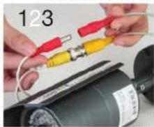
natural_image
Close-up of hands connecting red and yellow electrical components to a motor (no visible text or symbols)

natural_image
Close-up of hands holding a red and black electrical plug (no text or symbols visible)PICTURE 2-10
STEP 4. Repeat for each camera included with your package to ensure proper connection and function.
STEP 5. Connect the single end of the power splitter to the power adapter.
STEP 6. Plug the power adapter into a surge protector. You should now see a live video food from each of your cameras.


natural_image
Close-up of hands connecting black cables to a black electronic device with red connectors (no visible text or symbols)PICTURE 2-11
Some camera bundles may contain more than one camera power supply and splitter. Repeat the steps above as necessary to connect all of your cameras. For bundles containing multiple types of cameras, make sure to connect to the proper power supply as mixing and matching may either cause damage or insufficient power to your cameras.
You may now mount your cameras.
CAMERA PLACEMENT
When installing your camera, it is important to select a proper site not only for field of view, but for other considerations as well:
Distance from viewing/recording device. The further the camera is from the DVR or monitor, the higher the chances of signal degradation. Typical 75Ω Video Cable provides acceptable signal at distances up to 200° (60m). At greater distances, UL-Listed shielded RG59 should be used. The camera's power supply should be located as near to the camera as possible when the distance exceeds 200° as the power level will drop over extended distances resulting in a decrease in video quality.
Do not place near high voltage wires or other sources of electrical interference. Electrical interference will degrade the quality of the signal.
Place camera out of reach to avoid damage.
Avoid direct exposure to weather. Do not place the camera where rain or snow will hit the lens directly nor should the camera be placed so that the sun or bright light shines directly into the lens. Your camera is weatherproof, but it will not work when submerged in water. Ensure that all power and video connections are not directly exposed to water and are protected from the elements.
Indoor cameras should not be used outdoors. Even if they are in a sheltered location, they can still suffer damage due to humidity, dust and other environmental factors. Each camera has an ingress Protection (IP) rating which defines how protected the internal workings of the camera are from solid objects - such as fingers or bugs - dust and moisture. In an IP rating, there are two numbers that follow the letters "IP." The first represents the protection from solids while the second represents the housing's protection from moisture. A camera should have a minimum rating of IP65 for trouble-free use outdoors.
Mounting surface. The mounting surface must be sturdy and able to hold at least five times the camera's total weight.
Legal Considerations. Always check state and local laws before installing cameras. (2011 NEC 820.44)
Do not place camera behind a window. If there is a light source behind the camera, it can cause a reflection in the window that will obscure events on the other side of the glass. Likewise, the camera's infrared LEDs will reflect off the glass and shine into the lens, thus degrading the image.
Light levels should be approximately the same between camera and target
area. A camera in a brightly-lit area looking into a shaded area, or vice versa, may produce inadequate results.
The above are guidelines and the optimal location for your camera will depend on your unique circumstances. As a general rule, the locations highlighted in Green in the picture to the right indicate the best locations to mount your camera. Both locations are sheltered from rain or snow and offer good sight lines to allow your camera to monitor a wide area.

natural_image
Exterior view of a modern building corner with a green circular highlight on the roof (no text or symbols)PICTURE 2-12
Because your camera is weatherproof, it requires less protection than weather-resistant cameras and it can be placed in more exposed locations if needed. Keep in mind that most Q-See cameras are designed to operate between 14°F to 122°F (-10°C to 50°) with a relative humidity of up to 95%) and consider wind chill and other environmental factors when selecting your location. Specialty cameras are also available from Q-See which are able to operate in more extreme environments.
ADDITIONAL CONSIDERATIONS
Most users prefer to operate their systems with the DVRs recording only when motion is detected. This provides the most efficient use of the hard drive's capacity, plus making it easier for a recording to be located. However, if the a camera's location has a lot of "environmental" motion, such as a fan, wind, or the like, you will receive a lot of "false alarms." Usually, these events can be avoided by simply adjusting the placement of the camera. Other situations may require some fine-tuning of your settings. Chapter 8 Alarms, covers these settings in detail, but some easily avoidable situations are presented below:
TV/Computer Screens. If the camera can see a video screen, it will trigger a motion alarm any time the screen changes, whether there is a video or simply a screen saver. The screen can be masked out as described in Section 4.2. You can also reduce the level of motion sensitivity in specific areas of the screen by following the instructions in Section 8.3.
Fans/Machinery. Motion is motion and if machinery within the camera's field of view starts automatically, it will cause an alert. Similarly, if the camera is mounted on a wall with machinery on the other side that causes it to vibrate, that can also cause it to detect motion. Moving machinery within the camera's field of view may be masked off as mentioned above, or motion detection may be turned off for that channel. If there is another camera that covers access to the area where the machinery is located, you can set it so that the first camera will only be recording when triggered by a motion event detected by this second camera. See "Triggers" in described in Section 8.3.
Bugs. An occasional insect flying through the field of view is usually not enough to trigger an alert. However, some flying insects are attracted to infrared light and will swarm the camera. This is usually a temporary situation that occurs at only a certain time of the year. Lighting the area with yellow "bug light" of sufficient brightness can keep the camera operating in daylight mode and keep the infrared LEDs turned off. A second solution is to set the channel to record all the time, and turn motion detection off at night until "bug season" is over. Reducing the motion sensitivity (Section 8.3) can also reduce alerts as can using another camera to trigger recording as described above.
Additionally, keep your cameras clear of spider webs as the movement of the webs due to wind or critters in the web will cause an alert. The reflection of the infrared off the webs and back into the camera will also reduce the night vision range.
Snow/Rain. As with bugs, this is usually a seasonal event and may require motion detection to be temporarily disabled to avoid false alarms. However, positioning the camera further under shelter, such as closer to the wall and away from the edge of the eaves, can make the rain or snow too small for the camera to notice. Adjusting motion sensitivity may also help in some situations.
960H CAMERAS
A new standard for analog video cameras, 960H increases the width of the image from D1's 720x480 pixels to 960x480 pixels. When connected to a DVR with 960H capability, this allows the camera to take advantage of the wider aspect ratios of most monitors and HD screens to deliver a wider, clearer image, without the distortion caused by stretching to fit the screen. This is demonstrated in the image below:
natural_image
Exterior view of two white cars parked on a road with people nearby, surrounded by greenery (no visible text or symbols)Standard analog camera image stretched to fit HD aspect ratio.

natural_image
Exterior view of a roadside scene with several cars parked, some covered by personnel (no visible text or signage)960H camera image.
PICTURE 2-13
You can use 960H cameras with analog DVRs that don't have that technology, but the DVR will be unable to take full advantage of the capabilities for best results.
BASIC FUNCTIONS
CHAPTER 3
3.1 POWER ON/OFF
Before turning on the DVR, ensure that all connections are good.
POWER ON AND LOGIN
Connect the power supply and the DVR will power up. The LED labelled POWER on the front will illuminate and the DVR will display the live image from Channel 1.
Before you can proceed, you will need to log into the DVR.
STEP 1. Right-click with the mouse anywhere on the screen
STEP 2. Press the MENU button on the remote or press the STOP/ESC button on the front of the DVR to open the Control Bar which will appear at the bottom of the screen (Picture 3-3).
STEP 3. Once the Control Bar appears, click the Menu icon on the far left to open the
Main Menu (Picture 3-2).
STEP 4. The Login screen will appear. Enter the User Name and Password, admin and 123456 respectively using the Virtual Keyboard described in the last chapter. Click ENTER on the keyboard. You can change the password later as described in Section 4.6 User Management.

text_image
LOGIN User Name admin Password Login CancelPICTURE 3-1
You are now logged in.

IMPORTANT! If you are logging into the DVR for the first time, it is essential that you set your DVR to the proper date and time at this point. Doing so will allow you to search for events based on when they occurred as well as
avoiding complications by having multiple recorded files with the same date and time if you wait to make those settings. Complete instructions can be found in Section 4.1 Basic Configuration.
POWER OFF
The DVR will power down to a standby mode when the POWER button on the remote control is pressed, or when the SYSTEM SHUT DOWN icon is selected from within the MENU. In both cases, the SHUT DOWN window will appear and users must select OK to confirm. The hard drive will stop spinning and the system will shut down. For extended periods of inactivity, it is recommended that the DVR be disconnected from power either by turning off the power at the surge protector or unplugging the device.

text_image
MAIN MENU Setup Search Backup Information Master Alarm Disk Manage Upgrade Logoff Shut DockPICTURE 3-2
3.2 THE CONTROL BAR
When a user is logged in, pressing the ESC button on the DVR or right-clicking on the screen with the mouse will display the CONTROL BAR on the bottom of the screen.

text_image
Menu Screen Display Mode Dwell Color Zoom Volume Snapshot Playback PTZ Record Move Control BarPICTURE 3-3
The functions of the Control Bar are listed below. Screen Display Modes are covered on the next page and the other functions will be covered in more detail in the following chapters.
Menu: Opens the Main Menu.
Screen Display Mode: Choose the number of channels you wish to view at once. Channels without attached cameras will display "Video Loss." Clicking on the upward pointing arrows to the right of each icon will allow you to select which channels to view in that mode.
Dwell: Enable/disable automatic cycling between channels.
Color: Adjust the brightness, hue, saturation and contrast for any channel.
Zoom: Available in single screen display mode, this digitally enlarges a section of the display.
Volume: Adjust volume. This is only available if you have attached a microphone or audio-capable camera to the DVR.
PTZ: Opens the controls for optional Pan-Tilt-Zoom cameras.
Snapshot: Captures a still image from all channels and saves it to the hard drive.
Record: Begin manual recording on all channels.
Playback: Switches to Playback mode and brings up the Playback Control Bar.
Move Control Bar: Clicking this will allow you to reposition the Control Bar anywhere on the screen. Right clicking on the screen will hide the Control Bar.
DISPLAY MODE
By clicking on the display mode buttons on in the Control Bar you can quickly configure how your cameras' video feeds are displayed. The settings here will temporarily override the default configuration made in the Main Monitor tab in the Live menu (see Section
4.2 Live Configuration). You can select whether to view a single channel at a time, two channels in a picture in picture format, or view multiple channels in a split screen mode. In addition, users have the option to select how many channels to view at once as well as which channels will be shown in that multi-channel display. The number of display mode options and their configuration will depend up on the model of your DVR. With the exception of the nine-channel viewing mode on an eight-channel system, your DVR will not have the option to display more channels than it supports. If you have fewer than the maximum number of cameras connected to your DVR, the channels without cameras will remain black and display a "Video Loss" message.

natural_image
Row of eight geometric shapes with varying fill patterns and arrowheads, no text or symbols presentPICTURE 3-4
Click the 📄 icon beside the desired screen display mode to open the CHANNEL
SELECT menu.
Users can check any or all channels to display the live feeds (depending on the display mode chosen and the number of channels on the DVR). Click the 5-Box to confirm the settings before closing the
CHANNEL SELECT menu by clicking on the ✗ button.
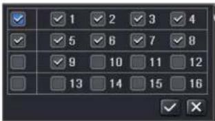
text_image
1 2 3 4 5 6 7 8 9 10 11 12 13 14 15 16PICTURE 3-5
You can move camera views to a new position by clicking and dragging the desired channel's display. When a channel's view is dragged into another area, the view that it replaces will move to the vacated location.
Double-clicking on any of the channels being displayed will bring that camera's video to full screen. Right clicking anywhere within the image will return the display to its previous mode.
Asymmetric Display
With the exception of the four-channel DVRs in this series and the QT536, users have the option of viewing cameras using an asymmetric display mode. This modes consists of one large image plus several smaller images. As described above, a camera's display can be dragged from one of the smaller windows into the larger window for easier viewing while maintaining a multi-channel display.
Picture in Picture
If you wish to only monitor two channels at a time, most QT DVRs (excluding the QT536) feature the Picture-in-Picture mode. The icon for this display mode is shown at the far right of
Picture 3-4.

PICTURE 3-6 PICTURE 3-7
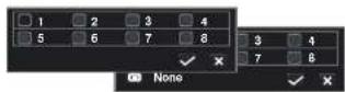
Clicking on the Picture-in-Picture button will open a pop-up window (Picture 3-6) allowing you to select which channel will be the main video feed. Clicking on the button in the lower left of that window will open a second pop-up window (Picture 3-7) allowing you to select the channel that will be displayed within the larger image. Note that the channel currently being used for the larger display will be darkened and not selectable.
3.3 LIVE VIEWING AND RECORDING
SWITCHING VIDEO OUTPUT
As described in Section 2.4 Video Display, the DVR is normally configured to output video signal to a 19" or larger monitor through the VGA port on the back. However, if you have attached a television to the Video Out port instead, then you will need to press and hold the ESCAPE, EXIT or STOP button (depending on model) on the front of the DVR for 10 seconds or until you hear a beep to indicate that the video mode has been changed. On the QT474, the video mode can be changed by pushing and holding the VGA/TV button.
LIVE VIEWING
The normal mode of the DVR is to display the live feed from the cameras. Configuring which channels will be displayed, naming the cameras and other display settings will be covered in SECTION 4.2.

PICTURE 3-8
In addition to the camera images, the DVR will display symbols regarding the status of each camera
| Symbol Meaning Symbol Meaning Symbol Meaning | ||||
| Scheduled Recording | Alarm Recording | |||
| Motion Detection | Audio Enabled | |||
RECORDING
Your DVR is configured to record whenever motion is detected. It is also set to record at the best setting possible. These settings work for most users, but each user's situation will be different and directions for adjusting these settings can be found in Section 4.3 Record Configuration.
3.4 QUICK PLAYBACK
Pushing the playback button on the DVR or remote will enable you to play back what has been recently recorded by launching Quick Playback.
Clicking on the Playback button within the Control Bar will begin the Quick Playback process as well.
Playback Button

PICTURE 3-9
The time period for the Quick Playback can be set by clicking the upward-pointing arrow
- icon next to the Playback button. You can chose to go back 2-, 5- or 10 minutes. This setting will apply whether you've selected playback on the remote, the front of the DVR or by clicking on the Playback button.

text_image
25:10 [Minutes] RECPICTURE 3-10
Only channels with recorded video will display their feeds and those without will be dark. As shown on the next page, a toolbar will appear below the display showing the playback controls. If you are using the mouse, clicking on the various controls will affect the video playback in a similar manner to using the front panel buttons or remote control. There may be additional video recorded before your starting point and you can go back to the beginning of the recording within this playback. You will, however, need to use the search feature described in Section 4.8 to locate video event recordings from other days, or earlier times.
PLAYBACK CONTROL BAR
The controls operate in a similar fashion to those of a conventional DVR or other video playback device but with a few additional commands available to you:

text_image
CAMERA 01 08/19/2011 12:02:12 CAMERA 02 08/19/2011 12:02:12 CAMERA 03 Puw Power Abstance Reverger screen today Hub Zoom color off Rscup Volumes Retirems 08/19/2011 12:02:12 08/19/2011 12:02:12 Camera Name >>1 X08/19/2011 12:02:00 Stop Fast Forward Previous Record Playback Speed Playback Progress Bar Next RecordPICTURE 3-11
Previous/Next Record: Moves to the prior or following recorded event, respectively.
Fast Forward/Rewind: In addition to their normal operation, clicking on these buttons multiple times will speed up or slow down the rate or progression - forwards or backwards - through the file. The speed can also be selected directly by clicking on the small upward pointing arrows to the right of each button. You can select from 1/4 speed to 16-times normal speed forward and rewind speeds of 8-times, 16-times and 32-times normal speed. The current speed will be displayed at the bottom center of the Playback bar.
Screen Display Mode: As with the Control Bar, these icons allow you to choose the number of channels you wish to view in playback. Clicking on the upward pointing arrows to the right of each icon will allow you to select which channels to view in that mode. Channels with no recordings will appear blank.
Zoom: Available in single screen display mode, this digitally enlarges a section of the display. Select this tool and then click and drag to select a portion of the video feed to enlarge it. Clicking and dragging within the zoomed-in area will allow you to move to other areas of the image. Right-clicking will return the video to regular display mode.
Color: Adjust the brightness, hue, saturation and contrast for any channel. Please note that this will only effect the playback for this channel on the DVR itself. It will not change the recording.
Playback Progress Bar: The slider moves along the Playback Progress Bar as the video plays. Moving this with the mouse will go to another segment of the video. You can move to another point in a single video by first clicking on that channel and then moving the slider to the desired time. Other channels will continue progressing normally.
Trim: Using this tool allows you to save a segment of the video record rather than having to back up the entire file.
To select a segment move the Playback
Progress Bar to before the desired location in the video and begin playback. Once you reach the desired starting point, click on the Trim button to set the beginning of the clip. The button's icon will
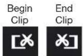
PICTURE 3-12
flip indicating that it is waiting for you to select the ending point. When you have reached that point, click the button again to complete your edit. The starting and ending times will be displayed at the bottom of the Playback Control Bar.
Backup: Once you have created your video clip, the Backup button will turn white indicating that you can save your clip directly to a USB drive connected to the USB port on the front of the DVR. The drive must be connected before clicking on the Backup button.
When the Backup button is clicked, the Backup window will open. It will list details about the file and the storage media that you have connected. If you have more than one drive connected - including ESATA, USB CD/DVD burners or other external media, you can chose the desired destination in the Storage Media pull-down.
If you do not have enough space on the disk to save your file, you may select Disk Cleanup to remove all files from that disk.

PICTURE 3-13

text_image
BACKUP INFORMATION Start Time: 98°19'02'11 01:24:12 End Time: 98°19'02'11 01:24:06 The Number of Files: 1 Save (RGB): .255 Storage Media: 0.257 New (New) 9.949 Backup Filter: ✓ Save Time Type: 0.07 Disk Cleanup CancelPICTURE 3-14
Chose the format in which you want to save your video clip. The .DVR format requires a special player program which will be included in a second folder on the drive. The .AVI format will work with most standard media playback software on PC or Mac computers. If selecting .AVI as the format for your files then you should deselect the Backup Player box. Click Start to begin the download and the progress bar at the bottom will fill up as the file is transferred.
For more information regarding backing up files, please see Chapter 5.

IMPORTANT! If you have audio recorded along with the video, you MUST select the ,DVR format in order to preserve it. Be sure to check the box next to
Desktop Player to also download the player program which can then be used. The file - with audio intact - to the more conventional .AVI format.
MAIN MENU SETUP
CHAPTER 4
4.1 BASIC CONFIGURATION
This chapter is intended to help you get your DVR up and running before you activate any advanced features which are covered in later chapters. You can use the mouse, remote control and the buttons on the front of the DVR to operate your system, but for convenience, we will be discussing operations using the mouse. Information on P.T.Z. cameras and alarms will be found in their own chapters, Chapters 7 and 8, respectively.
MENU NAVIGATION
Navigation through the user interface is point and click. Double-clicking on an icon within a given menu will open that menu, or a submenu. The Main Menu is the starting point to reach all of the DVR's settings and features. Selecting the Menu icon on the left of the Control Bar or pressing the Menu button on the DVR and remote control open the Main Menu.
Main Menu
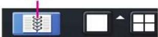
PICTURE 4-1
Clicking on any icon will open the relevant menu.

text_image
MOSK-NCNU Setup Search Backup Information Manual Alarm Disk Manage Upgrade Logoff Shut DownsPICTURE 4-2
SETUP
From the Setup menu select the Basic menu by clicking on its icon.

text_image
SECS Event Live Record Schedule Alarm Networks Users P T 2 AdvancedPICTURE 4-3

NOTE! When configuring your settings, you will always need to click Apply to save your current settings before closing the window with Exit otherwise your changes will be lost. You may click Exit or the close window box (X) in the upper right of the window to close without saving changes but an alert will pop up asking if you wish to save changes. Click OK to save changes or Cancel to continue without saving. You may select the Default button to restore your settings to those set at the factory.
BASIC MENU
There are three tabs covering System, Date & Time and Daylight Savings Time (DST). In the first tab, System you will set the date, time along with other desired settings.
System Tab
The following settings can be changed in this menu:
Device Name: This will display when you access the DVR remotely via your mobile device, a web browser or through the CMS software. Naming the device will help users recognize the device when monitoring numerous DVRs remotely.
Device ID: If you have multiple systems, you can give this device a numerical ID.
Video Format: Select between NTSC (North America) or PAL (Europe) video standards.
Password Check: By enabling this, a user will need to enter name and password when performing configuration operations.
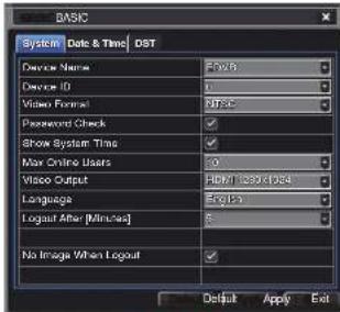
text_image
BASIC System Date & Time DST Device Name: Device ID: Video Format: Password Check: Show System Time: Max Online Users: Video Output: Language: Logout After [Minutes] No Image When Logout: Flash5 Flash6 Flash7 120x104 English Output Apply ExitPICTURE 4-4
Show Time: Displays the time on-screen in Live View.
Max Network Users: Set the maximum number of network connections - up to 10.
VGA Output: Chose the configuration that best fits your monitor. Options are: VGA 800x800, VGA 1024x768 (Default), VGA 1280x1024 and CVBS. NOTE: VGA is for VGA monitors while CVBS is for TV monitors connected using a BNC/PCA adaptor. Switching between VGA and CVBS will change the menu output mode. Please be sure to have the correct monitor on hand when changing output mode.
Language: Select your preferred menu language. The DVR will have to restart for this change to take effect.
Logout After... : You can have the DVR automatically log a user out after a period of inactivity. The period can range from 30 seconds (.5), 1, 3 or 5 minutes or never.
No Image When Logout: The monitor will not display the Live View when this box is checked.

IMPORTANT! After changing the Language or Video Format, the device will need to be restarted.
Date & Time Tab
Set date, time, time format and related configurations in this menu.

IMPORTANT! To maintain the integrity of recorded video, you should set the DVR to the correct date and time before making changes in other menus.
Setting the correct date and time before proceeding is essential to maintaining the integrity of your video records - especially for purposes of evidence. Making these straightforward settings should be your first priority before proceeding further within this manual. Changing the date and time after important videos have been recorded could result in the loss of those files.
Most of the options within this menu are self-explanatory. If you are unsure of your time zone, the date and time settings on your computer or searching online for "Time Zones" will quickly provide you with the information you need.
NTP Server: Using Network Time Protocol will keep your system's clock current by allowing it to occasionally receive updates from the selected server. Your DVR must be connected to the Internet for this feature to work. Please see the Remote Monitoring Guide for instructions.
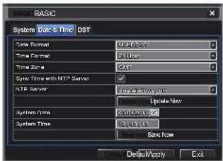
text_image
BASIC System Date & Time DST Time Format: 70 MHz Time Format: 31 MHz Time Zone: CAT Sync Time with NTP Server NTP Service: Time to Service port Upgrade Rate System Time: 30 MHz System Time: 80 MHz Save Now Default/Modify ExitPICTURE 4-5
DST Tab
This setting allows your system to adjust for time changes due to Daylight Savings Time. Again, your system must be connected to the Internet for this feature to work. As of this writing, Daylight Savings Time begins in most areas of North America on the 2nd Sunday in March and ends on the first Sunday in November. Both changeovers happen at 2 am. Allowing the DVR to make the change automatically ensures that files will not be lost as could happen by manually changing the hour.
Checking the box marked Daylight Saving Time will enable the DVR to switch the hour automatically.
The starting and ending periods must be set using the pull down options along with entering the hour manually. The Week radio button should be selected for this method. If your region switches to and from DST on a specific date, then chose the Date radio button and enter the needed information.
Click Apply to save your settings and Exit to close the menu.
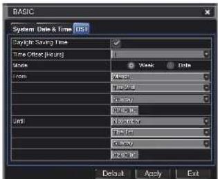
text_image
BASIC System (Date & Time) (D) Daylight Saving Time Time Other (Hours) Hours From: 100% 200% 300% 400% 500% 600% 700% 800% 900% 1000% Default Apply ExtPICTURE 4-6
Live configuration includes four submenus: Live, Main Monitor, Spot and Mask.
Live Tab
Use this menu to set camera names and adjust picture colors, brightness, hue saturation and contrast for optimal picture results.
You can individually name cameras by highlighting the field for each camera. The virtual keyboard will appear allowing you to enter characters, numbers and symbols with case sensitivity. ENTER will save the name and return to the LIVE menu. ESCAPE will exit the keyboard without saving.
You can enable or disable the display of the cameras' names and recording status (see Section 3.3) by using the check boxes.
You can configure the color settings for each channel individually. Adjust image saturation, hue, brightness, and contrast by clicking on the Setting button for each individual camera or for all of them simultaneously by selecting the All button before making the settings. This window can also be reached by clicking the color button on the Control Bar.
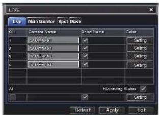
text_image
Live Main Monitor Spot Mask Color Camera Name Spot Name Color 1 Camera Name Setting 2 Camera Name Setting 3 Camera Name Setting 4 Camera Name Setting Previewing Options Default Apply ExtPICTURE 4-7
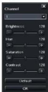
text_image
Channel 1 Brightness 128 Hue 128 Saturation 120 Contrast 128 Default OKPICTURE 4-8
Main Monitor Tab
Select the configuration of your display.
Split Mode allows you to choose from single view, 2x2, 2x3, 3x3, 4x4 (depending on model) views on a screen at one time. You can also select which channels will be displayed.
Channels can be grouped and the display will cycle between groups. Any individual channel can be shown in more than one group.
Dwell Time: This is the time interval the display will spend showing a group before moving on to the next group.
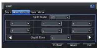
text_image
Live Mode Spin Mask Split Mode (OK) 1 2 3 4 5 6 Dwell Time 1 Default Apply ExitPICTURE 4-9

NOTE! If viewing remotely on a computer with dual monitors, the display must be on the main monitor.
Spot Tab
This allows select feeds to be viewed on a separate monitor that is connected to the DVR but may be in another room, for example. There will be no menu access on this auxiliary display.
Only one channel can be displayed at a time on this monitor. You may create groups of channels or designate a single channel as a group. A channel may be placed within more than one group. Select the order of the channels and their dwell time. Use the left and right arrows to switch between groups.
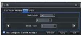
text_image
LME Live Main Monitor LME Mask Split Mode: 50% 1 Dwell Time: 5% Max Group 18, Current Group 1 Default Apply ExitPICTURE 4-10
Mask Tab
Set up masks on individual cameras to block out select areas on each screen. This is to grant privacy in situations when other users may be able to view the camera feeds and you wish to restrict viewing of certain areas or activities.
Click on the Setting button next to a given camera to apply a mask to its view.
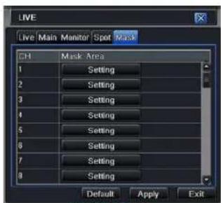
text_image
LIVE Live Main Monitor Spot Mask CH Mask Area 1 Setting 2 Setting 3 Setting 4 Setting 5 Setting 6 Setting 7 Setting 8 Setting Default Apply ExitPICTURE 4-11
Up to three areas may be masked in an image. Simply click and drag to cover the area. To delete, double-click on a mask.
Right-click to exit the screen, your masks will be saved.
The masks will appear on that channel's image in the live area as well as on recordings.

text_image
2000-12-00 14:11:24 T:531PICTURE 4-12
QT4 Series DVRs are set to record in real-time (30 frames per second) in the CIF format. Depending on the model, one or more channels may be set to record in the higher resolution in real-time, or all channels may record in D1, but at a reduced frame rate. QT5 Series DVRs, along with the QT454, are configured to record in real-time on all channels in the high-resolution D1 format. SDI DVRs will only record at 1060p resolution. The QT2124 can only record in the CIF format. There are five sets of options; Enable, Record Bitrate, Time, Stamp and Recycle Record.
Enable Tab
Select some or all of the cameras to record to the DVR. Depending on your DVR model, you can set up to 16 cameras to record audio in addition to video. This will require cameras equipped with microphones or separate microphones co-located with the camera(s). You can globally select all the cameras regardless of their individual settings by selecting the All box below each column.
Record Bitrate Tab
Set up the resolution, quality, encoding, quality and maximum bitrate of the video stream according to your needs. You can set each camera individually, or globally by using the All function at the bottom of the window.
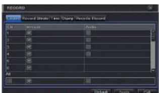
text_image
RECORD Record Stream: Time Sharing Recycle Record File Edit View Insert F 100 F 100 F 100 F 100 F 100 F 100 F 100 All Unknown Name OffPICTURE 4-13
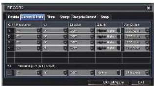
text_image
RECORDS Enable Update Time Snap Time Record Snap 1 2 3 4 5 6 7 8 9 10 11 12 13 14 15 16 17 18 19 20 21 22 23 24 25 26 27 28 29 30 31 32 33 34 35 36 37 38 39 40 41 42 43 44 45 46 47 48 49 50 51 52 53 54 55 56 57 58 59 60 61 62 63 64 65 66 67 68 69 70 71 72 73 74 75 76 77 78 79 80 81 82 83 84 85 86 87 88 89 90 91 92 93 94 95 96 97 98 99 100PICTURE 4-14

NOTE! While each camera can have its resolution and frame rate set independently of the other cameras, the DVR may limit the frame rate available to a camera based on the settings of other cameras.
| Parameter | Options | What It Means |
| Resolution | D1, CIF 1080P | D1 = Full TV resolution, CIF = I/2 D1. D1 takes more room on the hard drive than CIF1080P = Full HD resolution. Only available (and only option) on DVRs with SOI. Will only record at 7FPS. (see below). |
| FPS | 1-30 | Frames per second. More frames makes for smoother video but takes up more room on the hard drive. |
| Encode | VBR, CBR | Variable Bit Rate versus Constant Bit Rate. VBR provides better image quality for video with motion in it, but at the expense of a larger file size. |
| Quality | Lowest – Highest | Only available when VBR is selected. The higher the quality, the more drive space required. CBR's default setting is for higher quality. |
| Max Bitrate | 256-2084kbps | This sets the maximum bitrate that each camera will record at with VBR encoding selected. |
Time Tab
You can set the length of time the DVRs record an event before and after a motion detection or alarm is triggered as well as how long an individual record is preserved.
Pre-alarm record time: This sets the length of time showing events prior to a motion detection or sensor-triggered event that is included in the record.
Post-alarm record: Sets the length of time - from 10 to 60 seconds - that is added to the record after the event is finished.
Expire time: The time - up to 60 days - that an event is saved on the drive before it could be overwritten (See Recycle Record below).

text_image
FEBRU File Edit View Insert Tools Help Window Help Options Help 1.0 2.0 3.0 4.0 5.0 6.0 7.0 8.0 9.0 10.0 11.0 12.0 13.0 14.0 15.0 16.0 17.0 18.0 19.0 20.0 21.0 22.0 23.0 24.0 25.0 26.0 27.0 28.0 29.0 30.0 31.0 32.0 33.0 34.0 35.0 36.0 37.0 38.0 39.0 40.0 41.0 42.0 43.0 44.0 45.0 46.0 47.0 48.0 49.0 50.0 51.0 52.0 53.0 54.0 55.0 56.0 57.0 58.0 59.0 60.0 61.0 62.0 63.0 64.0 65.0 66.0 67.0 68.0 69.0 70.0 71.0 72.0 73.0 74.0 75.0 76.0 77.0 78.0 79.0 80.0PICTURE 4-15
You can set up all channels with same values by selecting All and then configuring one channel.
Stamp Tab
Select which cameras will display their ID and date stamp and where it'll appear on the screen.
Drag and drop the location of the camera name and date/time stamp to your desired location on the screen. This can be done individually or globally, A "Before" and "After" example is shown below.
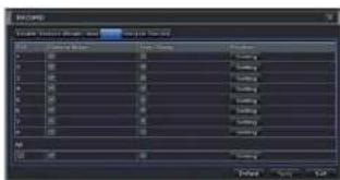
text_image
USE COLD Create Software Manager - Add As/Down Name: COLD Name: COLD Name: COLD Name: COLD Name: COLD Name: COLD Name: COLD Name: COLD Name: COLD Name: COLD Name: COLD Name: COLD Name: COLD Name: COLD Name: COLD Name: COLD Name: COLD Name: COLD Name: COLD Name: COLD Name: COL Name: COLD Name: COLD Name: COLD Name: COLD Name: COLD Name: COLD Name: COLD Name: COLD Name: COLD Name: COLD Name: COLD Name: COLD Name: COLD Name: COLD Name: COLD Name: COLD Name: COLD Name: COLD Name: COLD Name: CCL Name: COLD Name: COLD Name: COLD Name: COLD Name: COLD Name: COLD Name: COLD Name: COLD Name: COLD Name: COLD Name: COLD Name: COLD Name: COLD Name: COLD Name: COLD Name: COLD Name: COLD Name: COLD Name: COLD Name: CCOL Name: COLD Name: COLD Name: COLD Name: COLD Name: COLD Name: COLD Name: COLD Name: COLD Name: COLD Name: COLD Name: COLD Name: COLD Name: COLD Name: COLD Name: COLD Name: COLD Name: COLD Name: COLD Name: COLD Name: COLT Name: COLD Name: COLD Name: COLD Name: COLD Name: COLD Name: COLD Name: COLD Name: COLD Name: COLDPICTURE 4-16
text_image
04/29/2010 18:04:40 CAMERA02
text_image
CAMERA02 04/29/2010 16:04:40PICTURE 4-17
Snap Tab
In this tab, you can configure how many still images are taken, the quality of the images and the timing between them when the Snapshot button is pushed on the Control Bar.
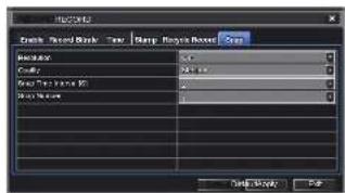
text_image
Waveform Track Record Break Tew Sharp Smooth Power Gray Waveform Circuit Smooth Time (ms) 0.5 0.5 0.5 0.5 0.5 0.5 0.5 0.5 0.5 0.5 0.5 0.5 0.5 0.5 0.5 0.5 0.5 0.5 0.5 0.5 0.5 0.5 0.5 0.5 0.5 0.5PICTURE 4-18
Recycle Record Tab
This is selected by default. Recycle record allows the DVR to record over old events when the hard drive is full. Otherwise, the DVR will stop recording when there is no more space available.
4.4 SCHEDULE CONFIGURATION
Your DVR is configured to record whenever motion is detected. If this is your desired setting then you will not need to make any changes. However, you may configure each channel to record at specific times based on time of day, motion detection or other sensor input. There are three tabs; Schedule, Motion and Sensor
Schedule Tab
The schedule for automatic recording can be set either of two ways.
- By highlighting individual hours for specific days by using the pencil tool in the upper right of the window. The adjacent eraser tool removes the highlighting in a block. Double click on either the pencil or eraser tool to turn them off. Settings can be copied and applied to any or all of the channels and to any other day.
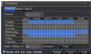
text_image
SCHEDULES Monday Mode: Calendar Channel 1 20:00 24:00 00:00 12:00 16:00 20:00 Sunday Monday Tuesday Wednesday Thursday Friday Saturday Apply Settings to Edit Channel Copy Double-click and setup schedule Default Apply ExitPICTURE 4-19
- Blocks of time to be recorded can also be set up by double clicking on a field adjacent to a day. Multiple schedules can be created and saved with start and stop times down to the minute. These can then be applied to multiple days and cameras.
Schedules made in one mode can be altered in another mode.
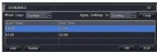
PICTURE 4-20
Motion Tab
Motion detected during the highlighted hours will cause the DVR to start recording. Setup is similar to that used in Schedule above. The default mode is for 24/7.

text_image
Schematic Waveform Frequency 1 0.0000 0.0000 0.0000 0.0000 0.0000 0.0000 0.0000 0.0000 0.0000 0.0000 0.0000 Apply Settings to: OK Cancel OK Cancel OK OK CancelPICTURE 4-21
Sensor Tab
This enables the DVR to record based on input from other sensors connected to the DVR. Like motion detection, it is default scheduled to be able to record at any time. It is also configured in the same manner as explained under Schedule.
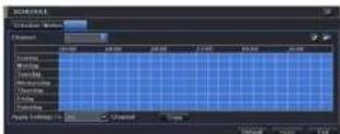
PICTURE 4-22
4.5 NETWORK CONFIGURATION
The Network Configuration window is used to control how your DVR works in a networked environment. This section offers a brief overview of how to set up your DVR so that it can be remotely monitored from another computer on your network, over the Internet or from mobile wireless devices. Full, in-depth instructions on the functions and settings available in this window are presented in the Remote Monitoring Guide which is on the disk that came with your system or which can be downloaded from our website at www.Q-See.com/Support. The four tabs in this window are Network, Sub-Stream, Email and Other Settings. If you will only be monitoring the DVR from another computer on your network, you will only need to use the first three tabs.
It is important that your DVR is connected to your network router and that the router is powered on before proceeding.
This window displays the information on the DVR's local network and Internet addresses which will allow you to access the DVR on a network. As discussed in the Remote Monitoring Guide, you will use the local network address to access your system from the same wireless or intranet network that the DVR is connected to. When you are outside of that area, you will use the Internet address shown (see below) or the DDNS address that you will set up.

IMPORTANT! The majority of routers available on the market since 2008 have Universal Plug and Play (UPnP) capability, which allows the DVR to connect automatically to the network. Consult the Quick Networking Poster or the Remote Monitoring Guide before changing Network settings.
Network Tab
HTTP Port - This is the port the DVR will use to communicate through the router. When accessing the DVR remotely from the Internet, you will need to enter your network's remote IP address (obtained in the next step) in the address bar of an Internet Explorer window. For example: http://88.116.0.25

text_image
NETWORK Network Substream Email Other Settings HTTP Port 53 Server Port 600C Options to IP address automatically ✓ IP Address 127, 433, 301, 110 Subsea Mask 255, 202, 255, 100 Gateway 127, 433, 301, 110 Preferred DNS Server 839, 433, 301, 110 Alternate DNS Server 127, 433, 301, 110 PPPoE User Name Password Test Default Apply ExitPICTURE 4-23

NOTE! The default value is 85. If port 85 is already occupied by another device on the network, then another port will need to be selected. Choose another number in the same range; 81-89. In this case, you will have to add the port to the IP address when entering it into the Internet Explorer window. For example, if the port is now 82, then you will need to enter http://88.116.0.25:82
Obtain IP Address Automatically – Clicking this box will obtain the IP address, subnet mask, and gateway IP from the router.
PPPOE - Selecting this enables Point-to-Point Protocol over Ethernet (PPPoE) which allows you to directly connect your DVR to the Internet through your modem. Do not use this unless you are connected to a modem instead of a router. Contact your ISP for your account information including user name and password. The TEST button will verify that your information is correct.
Definitions and descriptions of network configuration:
| Parameter Definition | |
| HTTP Port The | network port number for accessing the DVR from a remote location,The default port is 85 |
| Server Port The | port number for data. The default port is 6036 |
| Static IP | |
| IP Address The | IP address of the DVR on your network |
| Subnet Mask The server's subnet mask | |
| Gateway The gateway of the router | |
| DNS Server The | address of the Domain Name System (DNS) server |
| PPPoE | |
| User Name User | name of the broadband account |
| Password Password for broadband account | |
Substream Tab
The substream is the data that is sent to remote monitoring devices. Due to bandwidth concerns, these data streams are generally smaller than those sent directly to the DVR itself. These streams run in parallel with the main stream sent to the hard drive and they do not affect each other.
Substream settings are configured in the same manner as that used for the primary stream settings in the Record Bitrate tab in Section 4.3 Certain settings will be grayed out and cannot be changed due to throughput concerns. The definitions are repeated for your convenience:
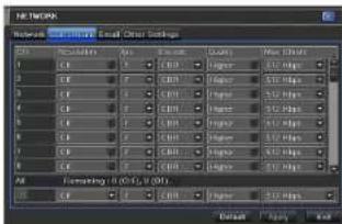
text_image
Network Settings Network Settings Email: Email Preset Settings 1.0 2.0 3.0 4.0 5.0 6.0 7.0 8.0 9.0 10.0 11.0 12.0 13.0 14.0 15.0 16.0 17.0 18.0 19.0 20.0 21.0 22.0 23.0 24.0 25.0 26.0 27.0 28.0 29.0 30.0 31.0 32.0 33.0 34.0 35.0 36.0 37.0 38.0 39.0 40.0 41.0 42.0 43.0 44.0 45.0 46.0 47.0 48.0 49.0 50.0 51.0 52.0 53.0 54.0 55.0 56.0 57.0 58.0 59.0 60.0 61.0 62.0 63.0 64.0 65.0 66.0 67.0 68.0 69.0 70.0 71.0 72.0 73.0 74.0 75.0 76.0 77.0 78.0 79.0 80.0 81.0 82.0 83.0 84.0 85.0 86.0 87.0 88.0 89.0 90.0 91.0 92.0 93.0 94.0 95.0 96.0 97.0 98.0 99.0 100.0PICTURE 4-24
| Parameter Options What It Means | ||
| Resolution CIF | CIF = 352 x 240 pixels. Only this resolution is available in the substream. | |
| FPS 1-30 | Frames per second. More frames makes for smoother video but may not be possible due to bandwidth. | |
| Encode VBR, CBR | Variable Bit Rate versus Constant Bit Rate. VBR provides better image quality for video with motion in It, but at the expense of a larger file size. | |
| Quality | Lowest - Highest | Only available when VBR is selected. The higher the quality, the more drive space required. CBR's default setting is for higher quality. |
| Max Bitrate | 256-2084kbps | This sets the maximum bitrate that each camera will record at with VBR encoding selected. |
Email Tab
This tab allows you to set how your DVR will send out e-mail alerts. You will be able to send e-mail alerts to three addresses.

NOTE! Depending upon your settings, the system can generate a lot of e-mail alerts. For that reason, we recommend setting up a dedicated e-mail address specifically for the system to send alert notices. If you do not have your own e-mail system (such as a corporate mail server) you should consider using a free e-mail provider. However, because many free e-mail services allow only a limited amount of e-mail traffic we specifically recommend using Google's
Gmail service with its higher limit. Similarly, you will want the alert emails to go to a different account than the one sending them. This will case your management of these alerts and help keep your mail account from overflowing.
If you do not have your own e-mail system, please set up a free account which the DVR can use to send out alerts before proceeding.
For the example below, we will use Gmail. The settings can be found under Options when logged into your Gmail account.
Clicking on any of the fields will bring up the virtual keyboard allowing you to enter the data. The virtual keyboard is capable of handling upper and lower case letters as well as numbers and symbols. Click the ENTER button to enter your input or ESC to exit the field without applying any changes.
SMTP Server: smtp.gmail.com
Port: 465 (standard port for Gmail - others may vary)
SSL Check: You will need to select this for Gmail. Other ISPs may vary.
Send Address: Enter your new address. This will appear on alert emails sent from the DVR
Password: Enter the password you created for this account. Remember, it will be case-sensitive.
Receive Addresses: You may set up to three e-mail addresses to receive alerts. It is strongly advised that you do not use the same address that the DVR is using to send alerts.
Advanced
Attaching Image Amount: The alert emails can include up to three images
Snap Time Interval: The interval of the images can range from every second to every five seconds.

text_image
NETWORK Network Sub-stream Enter Other Settings SMTP Server Port SSL Check Send Address Password Receive Address1 Receive Address2 Receive Address3 Test Advanced Attaching Image Amount 1 Snap Time Interval[5] Default Apply ExitPICTURE 4-25
Other Settings
Commercial ISPs provide their customers with dynamic addresses (IP numbers). These numbers can change from time to time depending upon your service provider. When they do, you will lose the ability to remotely access your DVR from your mobile phone or other out-of-network device. To prevent this from happening, we recommend using a Dynamic Domain Name Service (DONS). This will give you a domain name that can be linked to your IP address and will automatically – and invisibly – forward remote connections to your network when the IP address changes.
Q-See offers DDNS for free at MyQ-See.com. Create a domain name, user name and password before proceeding. DynDNS.com also offers a similar free service. This is covered in-depth in the Remote Monitoring Guide.
Select the box in the DDNS field to enable DDNS. You will then enter the user name, domain name and password you created into the appropriate fields. You can also select the interval in days at which the DDNS checks to see whether your IP address has changed. Intervals range from every 30 minutes to once a day.

text_image
NETWORK Network Substream Email Official Settings DONS DONS Server MYO Size.com User Name myone@myoalskpress.com Password mysecscscn.ipspassword Host Domain myocount myo-see.com DONS Update (Hours) 3 UPnP Text Default/Apply ExitPICTURE 4-26
You can now access the DVR remotely by inputting that domain name into the web browser.
4.6 USER MANAGEMENT
USER ACCOUNTS AND PASSWORDS
You can set up accounts for each individual user and grant them control of select parts of the surveillance system. An administrator account is already created on the DVR. Additional accounts can be created for users but only one administrator account is allowed.

PICTURE 4-27
To add a user select the Add button and the ADD USER window will open. It will have two tabs; General and Authority
General Tab
Input the name, password and select the type of user – normal or advance.
If you only want this user to be able to access the DVR from a specific computer on the network then select the Binding PC MAC
Address option and then enter the MAC address of that computer.
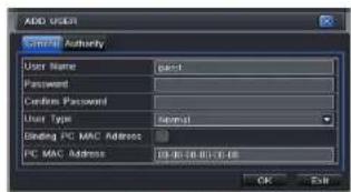
text_image
ADD USER Send Authority User Name Direct Password Custom Password User Type Script Binding PC MAC Address PC MAC Address 10.00.00.00.00 OK SubPICTURE 4-28
Authority Tab
In this tab you can give this user access to all or part of the system and its functions.

text_image
ADD LOGO General Settings Log View Audio Talk Format Log to Load View System Setup Data Manage Data Manage System Setup Data Manage System Setup Data Manage System Setup Data Manage System Setup Data Manage System Setup Data Manage System Setup Data Manage System Setup Data Manage System Setup Data Manage System Setup Data Manage System Setup Data Manage System Setup Data Manage System Setup Data Manage System Setup Data Manage System Setup Data Manage System Setup Data Manage System Setup Data Manage System Setup Data ManagePICTURE 4-29
Setup button – Modify user's name, type, binding PC Mac address and etc. With the exception of changing the password, the Admin account may not be modified.
Delete button – Remove a user from the system
Change Password button – Modify a user's password. The admin password may be changed. The default is 123456.
To change a password, simply click on the button and enter the current password in the pop-up window, along with the desired new password in the New Password and Confirm Password fields before clicking OK to save and Exit to close the window.
4.7 ADVANCED
In this set of commands, the user can erase all the settings, import or export data files to and from the DVR and control who can remotely access the DVR through three submenus: Reset, Import/Export and Black/White List.
RESET
Clicking on this option will open a warning dialogue asking you to confirm that you wish to remove all settings and reboot the system. You must select OK to continue with the reset or hit CANCEL to exit without changes.

text_image
Advance Setup Reset Import / Export Block / Active Ltd ExitPICTURE 4-30
IMPORT/EXPORT
Use this interface to export select data files to mobile Flash drives or an external USB drive through the backup function. Specific data files can also be retrieved from mobile or external storage devices and recorded onto the DVR.
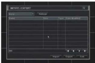
text_image
IMPORT / EXPORT Name Inspector Balance Sizeiger Type Data Modified OK Import Export EndPICTURE 4-31
BLOCK/ALLOW LIST
From here, an authorized user can control which computer users are allowed to access the DVR.

text_image
BLOCK/ALLOW LIST IP: IP From 1 108.160.000.000 2 900.000.000.000 3 900.000.000.000 4 900.000.000.000 To: 138.160.000.000 900.000.000.000 900.000.000.000 900.000.000.000 Default Apply ExitPICTURE 4-32
The Block List is used to deny access to remote computers within a certain IP address segment.
The Allow List is used to permit access by users from select IP address segments.
EXAMPLE: You wish to block access to the DVR from computer users within the IP address segment ranging from 196.168.000.002 to 196.168.000.004. Select the Block button and then enter the first segment in the IP From field and the last address within the segment in the To field. You may add additional segments before hitting Apply to save your settings and then exiting this window.
4.8 FILE SEARCH, PLAYBACK AND MANAGEMENT
Access the recordings on the DVR, play them back and backup the recordings to an external storage device.
Four submenus appear in this section: Time Search, Event Search, File Management and Image.

text_image
MAIN MENU Setup Search Backup Information Manual Alarm Disk Manage Upgrade Logoff Shut DownPICTURE 4-33

NOTE! Throughout this window, if the screen resolution is VGA 800*600, the time search interface will show a Hide button. Clicking on this button will expand or minimize the entire interface as needed.
TIME SEARCH
Search for an event within a range of dates and times.

text_image
SEARCH Time-Track Event Search File Management Start Time 00:00 04:00 08:00 12:00 16:00 20:00 Sina Mio Tu Wei Trt Fr Sa 1 2 3 4 5 6 7 8 9 10 11 12 13 14 15 16 17 18 19 20 21 22 23 24 25 26 27 28 29 30 31 3 4 5 6 7 8 4 5 6 7 8PICTURE 4-34
Select which channel you wish to search and the screen display mode. The Calendar icon in the Start Time window allows you to select a start date. Highlighted dates indicate that there is recorded data for those days.
The vertical column of numbers to the left of the grid are the available channels. The horizontal headings are blocks of time within the day.
You can select which time to begin the review by entering it in the start time window or clicking on the time grid and moving the yellow line to the approximate start time.
Clicking on the PLAY button will begin the playback from the time selected. It will also bring up a playback toolbar allowing finer control of the playback process.
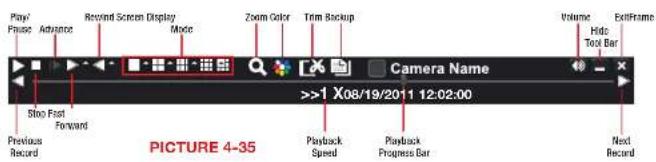
text_image
Play/Pause Advance Record Screen Display Mode Zoom Color Trim Backup Volume Hide ExitFrame Volume Hide Tools Bar Slow First Forward Previous Record Playback Speed Playback Progress Bar Next Record >>1 X08/19/2011 12:02:00 PICTURE 4-35EVENT SEARCH
Selecting this tab will bring up a list of recorded events. Your DVR is configured by default to record when motion is detected. You can choose whether to display events triggered by Motion, Sensor or both. These files are saved as events.
Select the date you wish to search and click the Search button. You will be presented with a list of recorded events.
Select the channel and click the Double-click the event file you wish to play back.
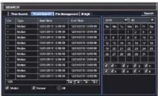
text_image
MARCH New Search May 2010 May 2011 May 2012 May 2013 May 2014 May 2015 May 2016 May 2017 May 2018 May 2019 May 2020 May 2021 May 2022 May 2023 May 2024 May 2025 May 2026 May 2027 May 2028 May 2029 May 2030 May 2031 May 2032 May 2033 May 2034 May 2035 May 2036 May 2037 May 2038 May 2039 May 2040 May 2041 May 2042 May 2043 May 2044 May 2045 May 2046 May 2047 May 2048 May 2049 May 2050 May 2051 May 2052 May 2053 May 2054 May 2055 May 2056 May 2057 May 2058 May 2059 May 2060 May 2061 May 2062 May 2063 May 2064 May 2065 May 2066 May 2067 May 2068 May 2069 May 2070 May 2071 May 2072 May 2073 May 2074 May 2075 May 2076 May 2077 May 2078 May 2079 May 2080 May 2081 May 2082 May 2083 May 2084 May 2085 May 2086 May 2087 May 2088 May 2089 May 2090 May 2091 May 2092 May 2093 May 2094 May 2095 May 2096 May 2097 May 2098 May 2099 May 2100PICTURE 4-36
FILE MANAGEMENT
From within this tab you can lock, unlock or delete recorded events from the drive.
Clicking the Search button in the upper right of the window will bring up a list of events to be displayed. Results can be filtered by selecting date and channels if desired.

text_image
SEARCH Time Search Event Search Image Search GT Start Time End Time Status 1 03/02/2018 16:17:22 1 03/02/2018 16:04:02 1 03/02/2018 15:08:42 1 03/02/2018 14:01:49 1 03/02/2018 14:08:26 1 03/02/2018 13:35:18 A/B Delete LockPICTURE 4-37
LOCK - Selecting a file and then clicking the Lock button will protect the event from being overwritten or deleted unless the entire drive is reformatted
UNLOCK – This will remove the file protection and the event recording can be deleted or overwritten normally
DELETE – If the event is not Locked, this will remove the selected event from the DVR.

NOTE! If the status shows "Writing" it means that the sector on the hard drive where the file is located is still being written to. You cannot delete the file until the file is completed and the word "Writing" disappears.
IMAGE
This tab functions much as the Event Search tab by allowing you to search for and view the still images captured when you click on the Snapshot icon on the Control Bar. These images are stored on the DVR's hard drive just as with video files.
Select the date to search, along with the start and end times to search between. You can also select which channels you want to include in the search. Clicking the Search button in the upper right of the window will bring up a list of available images.

text_image
SP-ARC1 Time Search ImageEvent Search File Management Search Start Time 12 / 23 / 2010 ms End Time 12 / 23 / 2010 ms 28 / 38 / 38 2.94 6.765 3:13 Delete Lock Save Save AllPICTURE 4-38
After the search is completed, a count of available images will be displayed along with the first still image. The buttons at the bottom of this tab allow you to navigate through the images as well as save them for use outside the DVR.
DELETE - This will remove an unwanted image from the hard drive.
LOCK - This will prevent a file from being deleted. If a file is locked, this button will read UNLOCK.
SAVE/SAVE ALL – These buttons allow you to save individual or all of the images in the group to an external USB flash drive inserted in the USB port on the front of the DVR.
ARROW BUTTONS – Navigate to the first, last previous or next image in the group.
BACKUP
CHAPTER 5
This DVR supports backing up files to USB flash drives, USB hard drives and USB DVD burners through the USB port on the front panel. Remote backups can be performed over the Internet. Refer to Section 2.4 Remote Backup in the Remote Monitoring Guide.

NOTE! External USB hard drives used for backing up data will need to be in the FAT32 format. Most new drives will need to be reformatted before use with this DVR.
FORMATTING A USB DRIVE IN FAT32
To format a USB flash drive with FAT32, plug it into a PC running Windows XP or later. Go to My Computer to locate the drive's icon. Right click on it and select Format in the list of available options. Select FAT32 and check the box marked Quick Format before clicking Start.
For USB drives over 32GB in size, you should use a FAT32 format utility such as those available through CNET.com.
BACKING UP A FILE
Selecting BACKUP in the Main Menu will open the Backup configuration window.
The search for files to backup is much like the method used to search for files to play back as was covered in the previous chapter.
Set the start and end times as well as channel(s) you wish to back up. Clicking the Search button will bring up the search results in the Data Backup list box.

text_image
C1 01/09/2010 10:12:22 01/09/2010 11:04:22 01/09/2010 11:30:22 01/09/2010 11:37:22 01/09/2010 12:04:22 01/09/2010 12:33:22 01/09/2010 12:30:22 Start Time: 18:36 / 17:59 End Time: 18:36 / 17:59 Start Time: 18:36 / 17:59 End Time: 18:36 / 17:59 Start Time: 18:36 / 17:59 Start Time: 18:36 / 17:59 Start Time: 18:36 / 17:59 Start Time: 18:36 / 17:59 Start Time: 18:36 / 17:59 Start Time: 18:36 / 17:58 Start Time: 18:36 / 17:59 Start Time: 18:36 / 17:59 Start Time: 18:36 / 17:59 Start Time: 18:36 / 17:59 Start Time: 18:36 / 17:59 Start Time: 18:36 / 17.58 Start Time: 18:36 / 17:59 Start Time: 18:36 / 17:59 Start Time: 18:36 / 17:59 Start Time: 18:36 / 17:59 Start Time: 18:36 / 17:59 Start Time: 18:36 / 2 Start Time: 18:36 / 2 Start Time: 18:36 / 2 Start Time: 18:36 / 2 Start Time: 18:36 / 2 Start Time: 18:36 / 2 Start Time: 18:36 / 2 Start Time: 18:36 / 2 Start Time: 18:42 / 2 Start Time: 18:42 / 2 Start Time: 18:42 / 2 Start Time: 18:42 / 2 Start Time: 18:42 / 2 Start Time: 18:42 / 2 Start Time: 18:42 / 2 Start Time: 18:42 / 2 Start Time: 2 Start Time: 2 Start Time: 2 Start Time: 2 Start Time: 2 Start Time: 2 Start Time: 2 Start Time: 2 Start Time: 2 Start Time: 2 Start Time: 2 Start Time: 2 Start Time: 2 Start Time: 2 Start Time: 2 Start Time: 2 Start Time: 2 EndPICTURE 5-1
Select specific events or select the All button. Clicking the Backup button will bring up the Backup Information window:
This window will present a summary of the number of files, starting and ending times, total size of the files and whether you have space available on the receiving storage media. Disk Cleanup will erase the contents of the storage media to make room. You can select which type of device you are recording to as well as what type of file you will be creating.
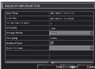
text_image
BACKUP INFORMATION Start Time End Time End Time of Start Start Time End Time Start Time End Time BackUp BackUp Player BackUp Type 9% Back Up Back Up CancelPICTURE 5-2
Save File Type: Choose between DVR and AVI. The former will save the video in a proprietary format while the latter will create a standard .avi file usable by most media playback software. If you choose the DVR format, you need to select the Desktop Player option (see Picture 5-2) as well. This will save a stand-alone playback program in a separate folder labeled Video Play on the same drive.
Clicking on the Start button will begin the backup and the progress bar will display the progress.
Windows PC - You may play AVI formatted files using Windows Media Player, QuickTime, DIVXplayer or other media players. The files can be opened and played in a similar manner to any other media file. You may need to download and install the K-Lite Codec as described above.
The Superplay.msi program is a PC-only application and is saved onto the same drive as video files when the Backup Player option is selected. Launch the software in the normal manner and then click on Open Path and navigate to the folder containing the video files and select the file you wish to play back.
Apple Macintosh - At this time, you must use the Remote Backup feature to save the file to your computer through the remote viewing software. See Section 2.4 of the Remote Monitoring Guide for instructions on this process.
You MUST select the AVI format when backing up the video file for playback on a Mac computer. You can use the QuickTime player or other video player and open the video file in the normal manner.
IMPORTANT CONSIDERATIONS
Audio
If you have recorded audio with the video file that you wish to back up, you MUST select the .DVR format for your file. You will also need to ensure that the box next to Desktop Player is selected as well. If you are sharing the video with anyone, such as law enforcement, the player will allow them to hear the audio along with seeing the video. You may also use the player to convert the file to the more conventional .AVI format and the audio tracks will be included in the video. Please note that files backed up via a Macintosh computer will not retain audio.
Locking the file
In situations where the video file is to be used as evidence, we recommend locking the file first as described in Section 4.8 File Search, Playback and Management. This can be done either locally on the DVR, or remotely through your mobile device or computer. Please see the Remote Monitoring Guide for instructions on performing this function away from the DVR. Once it has been locked, it cannot be erased or overwritten unless the entire hard drive is reformatted.
DVR MANAGEMENT
CHAPTER 6
6.1 INFORMATION
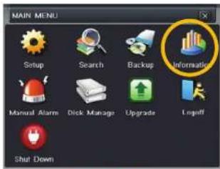
text_image
MAIN MENU Setup Search Backup Information Manual Alarm Dick Manage Upgrade Ingriff Shut DownPICTURE 6-1
This window enables the user to monitor the status of the system, its network connection, online users, history and events through five submenus: System. Event. Log. Network and Online Users.

text_image
INFORMATION INFORMATION System Event Log Networks Online Users Record OFC codePICTURE 6-2
SYSTEM INFORMATION
Data on the system's hardware, MCU (MicroController Unit), komel (if applicable) and firmware versions can be found here along with the device's name and ID.

text_image
SYSTEM Device Name EDVR Device ID 0 Hardware Version 302.0.x MCU Version Kernel Version Firmware Version 3.1.0.D Launch Date 2010-07-31 11:07:00PICTURE 6-3
EVENT INFORMATION
This window lists recorded events. This list can be searched by date, time, type of event and channel.

text_image
EVENT LIST M1 Type Senser Motion Video Loss Motion Senser Motion Video Loss Start Time 01/18/2019 18:17:22 01/26/2019 18:17:22 01/30/2019 18:04:02 01/33/2019 18:04:02 01/37/2019 18:04:02 01/41/2019 18:04:02 Start Time 01/18/2019 18:04:02 01/26/2019 18:04:02 01/30/2019 18:04:02 Start Time 01/18/2019 18:04:02 01/26/2019 18:04:02 01/30/2019 18:04:02 Start Time 01/18/2019 18:04:03 01/26/2019 18:04:03 01/30/2019 18:04:03 Start Time 01/18/2019 18:04:03 Start Time 01/26/2019 18:04:03 Start Time 01/30/2019 18:04:03 Start Time 01/33/2019 18:04:03 Start Time 01/41/2019 18:04:03 Start Time 01/46/2019 18:04:03 Start Time 01/51/2019 18:04:03 Start Time 01/56/2019 18:04:03 Start Time 01/61/2019 18:04:03 Start Time 01/66/2019 18:04:03 Start Time 01/71/2019 18:04:03 Start Time 01/76/2019 18:04:03 Start Time 01/81/2019 18:04:03 Start Time 01/86/2019 18:04:03 Start Time 01/91/2019 18:04:03 Start Time 01/96/2019 18:04:03 Start Time 02/5/2019 17:35:38 Start Time 02/6/2019 17:35:38 Start Time 02/7/2019 17:35:38 Start Time 02/8/2019 17:35:38 Start Time 02/9/2019 17:35:38 Start Time 02/9/2019 17:35:38 Start Time 02/9/2019 17:35:38 Start Time 02/9/2019 17:35:38 Start Time 02/9/2019 17:35.38 Start Time 02/9/2019 17:35.38 Start Time 02/9/2019 17:35.38 Start Time 02/9/2019 17:35.38 Start Time 02/9/2019 17:35.38 Start Time 02/9/4/2019 17:35.38 Start Time 02/9/4/2019 17:35.38 Start Time 02/9/4/2019 17:35.38 Start Time 02/9/4/2019 17:35.38 Start Time 02/9/4/20PICTURE 6-4
LOG INFORMATION
This window lists user activity within the system.

text_image
LOG LIST File Edit View Date Time Search admin 05/4/2018 14:07:30 127.600.000.000 Time Search admin 05/4/2018 14:02:21 127.600.000.000 Time Search admin 05/4/2018 14:07:18 127.600.000.000 Logan admin 05/4/2018 14:02:01 127.600.000.000 Logan P.T.2 Operation admin 05/4/2018 11:59:38 127.600.000.000 Logan P.T.2 Operation admin 05/4/2018 11:59:34 127.600.000.000 Logan P.T.2 Operation admin 05/4/2018 11:59:43 127.600.000.000 Logan P.T.2 Operation admin 05/4/2018 11:49:52 127.600.000.000 Logan P.T.2 Operation admin 05/4/2018 11:49:99 127.600.000.000 Logan P.T.2 Operation admin 05/4/2018 11:38:57 127.600.000.000 Logan admin 05/4/2018 19:54:54 127.600.000.000 Logan P.T.2 Operation admin 127.600.000.000 Logan P.T.2 Operation admin 127.600.000.000 Logan P.T.2 Operation admin 127.600.000.000 Logan P.T.2 Operation admin 127.600.000.000 Logan P.T.2 Operation Admin 127.600.000.00 Logan P.T.2 Operation Admin 127.600.000.00 Logan P.T.2 Operation Admin 127.600.000.0 Logan P.T.2 Operation Admin 127.600.000.0 Logan P.T.2 Operation Admin 127.600.000.0 Logan P.T.2 Operation Admin 127.6PICTURE 6-5
This record can be searched by type of operation, date and time, and etcetera. It can also be exported to external USB storage devices using the backup function.
NETWORK INFORMATION
This window shows the status of the DVR on the network including its assigned port, and other networking configurations.

text_image
NETWORK HTTP Port 0 Server Port 0 IP Address 000.000.000.000 Submit Mask 000.000.000.000 Gateway 000.000.000.000 Preferred DNS Server 000.000.000.000 Alternate DNS Server 000.000.000.000 Networking Approach Static IP Status Unconnected DDNS Unconnected MAC 00-00-00 00-00-00PICTURE 6-6
ONLINE USER INFORMATION
Information on remote users currently connected is displayed in this window.
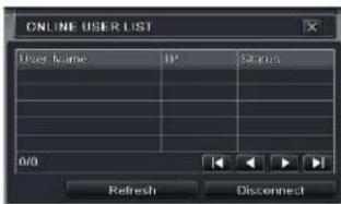
text_image
ONLINE USER LIST User name IP Status 0/0 Refresh DisconnectPICTURE 6-7
Refresh – Updates the list of online users
Disconnect – The Administrator can disconnect a selected user from the DVR. That PC will not be able to access the device for five minutes thereafter.
RECORD INFORMATION
This window provides information on your camera's recording resolution, the recording speed and what mode the camera is operating in. At the bottom is a bar indicating the percentage of the hard drive's capacity that has been used.
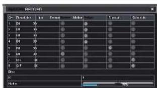
text_image
RGB Color: RGB Size: 12.5 Tuning: 0.0000 Volume: 12.5 Effect: OK Cancel OK Cancel OK Cancel OK Cancel OK Cancel OK Cancel OK Cancel OK Cancel OK Cancel OK Cancel OK Cancel OK Cancel OK Cancel OK Cancel OK Cancel OK Cancel OK Cancel OK Cancel OK Cancel OK Cancel OK Cancel OK Cancel OK Cancel OK Cancel OK Cancel OK CancelPICTURE 6-8
6.2 MANUAL ALARM
This displays the configuration of the manual alarm. See Chapter 8 for information on connecting and setting up alarms.

text_image
MANUAL ALARM Index Alarm Name IP Trigger 1 ALARM OUT 1 127.0.0.1 All Alarm Clear ExitPICTURE 6-9
6.3 DISK MANAGEMENT
This window displays information on the drive or drives mounted within the DVR including size, available space and status.

text_image
DISK MANAGEMENT ID Type Scale(D) Free(D) Status Properties Situten 10 F/U 0.00 Normal Release & Write Event Refresh Apply Format ExitPICTURE 6-10
The drive can be set to read only, which will disable recording, but will preserve the data currently stored within it.
If you have upgraded your system by installing a new drive (See Chapter 9) you will need to first format the new hard disk before recording. You can reformat the current drive if desired by selecting the Format option in the drop down menu.

WARNING! Reformatting the drive will delete all recorded files stored on the hard disk regardless of whether they are Locked!
Refresh will update the information about the drive.
6.4 FIRMWARE UPGRADE
This window will display firmware updates that are loaded on a USB flash drive in the front USB port.

text_image
UPDRANGE Name Properties Balance Type Width 100% OK Up Down Change OKPICTURE 6-11
Firmware upgrades are available from Q-See at www.Q-See.com/Support and may be found by looking up your specific model. Firmware should only be upgraded to fix a specific problem or add features as ongoing development may result in features being removed,
The firmware download should be loaded onto an empty USB flash drive from the downloading computer and then transferred to the DVR using a USB port.

IMPORTANT! Please make note of your settings before updating the firmware on a QT426 or QT446 as the upgrade process will restore factory defaults. Other models will retain their user settings.

NOTE! While a Macintosh computer can read and write to a drive in the FAT32 format, it cannot reformat a USB flash drive to that standard. We suggest that you use a PC to reformat your USB flash drive to FAT32 and it is recommended that you download firmware updates on a PC. Beginning with version 3.1.71, you can use the Upgrade feature in the Remote Monitoring software (see Section 2.5 of the Remote Monitoring Guide) to upgrade without a USB flash drive.

WARNING! Updating the firmware incorrectly or using the wrong update can permanently damage the chipset on the DVR and render it unusable. Updates are written to either resolve issues or add features to the DVR. If you are not experiencing performance issues or do not need a feature added by we recommend not running the update.
6.5 LOGOFF
Logging out of the DVR is recommended when there are multiple users or when physical access to the DVR is not restricted. Clicking on the Logoff icon will bring up a window asking for confirmation.
After logging off, a user can log back in by clicking on the Menu icon and entering their user name and password.
6.6 SHUT DOWN
This is a "soft power down" of the DVR. It shuts down the firmware and hard drive, but does not power down the DVR itself.

WARNING! It is vital that the DVR be instructed to shut down using the Shut Down menu option prior to unplugging the device in order to avoid damaging the firmware or hard drive itself.
PAN/TILT/ZOOM CAMERAS
CHAPTER 7
7.1 CONNECTING A PTZ CAMERA
All QT-Series DVRs can support one or more Pan/Tilt/Zoom, or PTZ cameras. These cameras connect to the DVR through the same ports as a conventional camera, but the control wires connect through the RS485 block on the back of the DVR. Picture 7-1, below, is only a representation and your actual connector may look different. Please consult Chapter 2
Connections and Controls to find the diagram representing your model for the location of your connector block.
The RS485 connector uses a single-direction protocol meaning that it can send commands out to the camera(s) but not receive any data back from the unit meaning that video images will be delivered through the video cable as with any other camera.
The DVR is set by default for RS485 to be disabled for each channel. Therefore, PTZ settings must be enabled before PTZ cameras can be utilized. This system supports 26 of the most common protocols including Polco-D and Polco-P.
When connecting a PTZ camera, the following should be taken into account:
• The 485 port of this DVR cannot parallel connect with the 485 port of another device
- The voltage between the A and B lines of the camera should be less than 5V.
RS-485
STEP 1. The data cable from the PTZ camera must be connected to the ports highlighted in Picture 7-1. Multiple PTZ cameras can be connected to this port, but you may require an expander port to do so.
STEP 2. Connect the other end of the cable to the proper pins in the connector on the camera
STEP 3. Connect the camera video and power cables as you would any other camera.

text_image
1 NO C 2 NO C CNTRL 12V A B 12345678PICTURE 7-1
7.2 PAN-TILT-ZOOM (PTZ) CONFIGURATION
If you are connecting optional Pan-Tilt-Zoom cameras, the controls are set from this window in
the Serial Port and Advanced tabs.
Serial Port Tab
You will need to consult your PTZ camera's manual for details regarding protocol and baud rate. Please note that the DVR may support more features than your camera offers including protocol and number of preset programs.
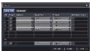
text_image
Cell Dot Advanced Cell Style: Abstract Cell Type: Normal Pixelation: 0.0000 Noise Level: 0.0000 Noise Ratio: 0.0000 Noise Value: 0.0000 Noise Scale: 0.0000 OK Cancel Apply HelpPICTURE 7-2
Cameras can be individually configured or a global set-up can be implemented through the All button.
Simulative Cruise is for use with PTZ cameras using an unsupported protocol to allow you to use at least some of the features.
PTZ Definitions and Descriptions:
| Parameter | Settings | What it Means |
| Address | 1-255 | The address of the PTZ camera |
| Baud Rate | 110-21600 | The speed that data is transmitted |
| Protocol | The communication protocol used by the camera. Supported protocols are; NULL, PELCOP, PELCOD, LILIN, MINKING, NEON, STAR, VIDO, DSCP, VISCA, SAMSUNG, RM110, HY |
Advanced Tab
You can set your camera to follow a preset program or set cruising or tracking behaviors by selecting the Setting button in the Preset, Cruise or Track columns respectively.

text_image
1.0.2 Save Point: OK 1.0.1 1 Setting Setting Setting Setting Setting Setting Setting Setting Setting Setting Setting Setting Setting Setting Setting OK Apply Add HelpPICTURE 7-3
Preset
Clicking a Setting button in the Preset column will bring up another window
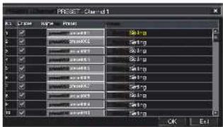
text_image
PREF: Chand1 OK ExitPICTURE 7-4
And, selecting Setting will bring up the camera view along with a control panel to program the camera's motion.

PICTURE 7-5
The dome's rotation can be controlled vertically, horizontally and diagonally along with its speed. The lens zoom, focus and iris (light level) can be set as well. Select the number you want to assign to this set of actions and click the Save button to save your preset. You can hide the control panel by clicking on the "-" button or right-clicking on the screen. The control panel can be unhidden by right-clicking on the screen again. The X button will exit the control interface.
Cruise
Selecting a Setting button from the Cruise column will open the Cruise window.
Select Add or double-click on an existing line to modify and the CRUISE PRESET window will open.
Delete will remove a selected cruise line Clear All will remove all of the cruise lines.

text_image
CREASE Name: 1 2 3 4 5 6 7 8 U/I Add Setup Delete Clear All OK ExitPICTURE 7-6
The set of icons to the right of the screen are used to configure each cruise setting.
Preview – Preview the cruise to ensure that you have the desired results.
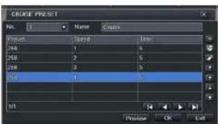
text_image
GULCE PREST Name: Name: Create Preview 1 2 3 4 5 6 7 8 9 10 Preview OK LeftPICTURE 7-7
| Name | Symbol | What it Does |
| Add | Opens a window to allow the user to set the speed and time of a new preset point. | |
| Delete | Deletes a preset point | |
| Modify | Opens the settings window for the selected preset point allowing you to change the settings | |
| Arrows | Enables the user to alter the position of a setting in the cruise order. | |
| Move a preset point all the way to the top of the order | ||
| Move a preset point up one position in the list | ||
| Move a preset point down one position in the list | ||
| Move a preset point to the bottom of the order | ||
Track
This interface is used to program the tracking routine for the camera. Clicking on the Track button will bring up the live view for that camera plus a control panel:
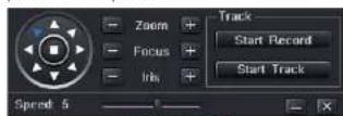
PICTURE 7-8
The user can control the dome's rotation direction, plus speed as well as the zoom, focus and iris.
Start Record – The system will begin recording the sequence of movements you perform on the PTZ control panel. Clicking this again will stop the recording.
Start Track – This will play back the tracking sequence you just recorded. Clicking on this button again will stop the playback.
ALARMS
CHAPTER 8
Many QT Series DVRs feature connections for external alarms – both input and output. Please consult Chapter 2 Connections and Controls to determine whether your model includes this feature and where the connection block is located. The alarm connector block shown in Picture 8-1 is only a representation and your actual connector may look different.
When an event is detected the system can notify local users or send notification to a monitoring service. At the same time, the system can accept signals from motion detectors, smoke detectors or other alarms and begin recording based on that input and your settings. You will need to have the manual for your alarm(s) handy to ensure the proper settings within the DVR.
8.1 ALARM INPUT
When attaching alarms, the following criteria must be met:
- The alarm input must be grounded.
- A grounding signal is required for the alarm input
- When connecting the DVR to another device - including another DVR - through the alarm input, a relay should be used to separate them.
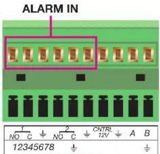
text_image
ALARM IN 1 NO C - + NO C - + CNTRL 12V A B 12345678PICTURE 8-1
| Parameter Grounding Alarm | |
| 12 | Ground line |
| Alarm Input 1, 2, ..., 8 becomes valid in low voltage. | |
| 1-NO C | Two NO activation outputs. |
| 2-NO C | |
| CTRL 12V Controls the power outputYou need to close the device power to cancel the alarm. | |
The accompanying diagram (Picture 8-2), along with your alarm's manual should be consulted to ensure proper connection.
• Normal open or Normal close type
- Parallel connect COM end and GND end of the alarm detector (Provide external power to the alarm detector).
- Parallel connect the Ground of the combo DVR and the ground of the alarm detector.
- Connect the NC port of the alarm sensor to the combo DVR alarm input(ALARM)
- Use the same ground with that of combo DVR if you use external power to the alarm device.

flowchart
graph TD
    A["+12V"] --> B["GND"]
    C["+12V"] --> D["GND"]
    E["Alarm Device Connection Terminal"] --> F["ALARM"]
    E --> G["GND"]
    H["Alarm Device Connection Terminal"] --> I["ALARM"]
    H --> J["GND"]
PICTURE 8-2
8.2 ALARM OUTPUT
The alarm output port should not be directly connected to a higher power load (greater than 1A) to avoid high current which may damage the relay. Use the co-contractor to establish the connection between the alarm output port and the load.
- 2 way relay alarm output (NO contact). Provides external power to external alarm device.
- To avoid overloading, please read the following relay parameters sheet carefully.
- RS465 A/B cable is for the A/B cable of the PTZ camera(s).
Relay Specification
| Model: JRC-27F | ||
| Material of the contact Silver | ||
| Rating (Resistance Load) Rated switch capacity 30VDC 2A, 125VAC 1A | ||
| Insulation Between contacts with same polarity 1000VAC 1minute | ||
| Surge voltage Between contacts with same polarity 1500V (10×160us) | ||
| Length of open time 3ms max | ||
| Length of close time 3ms max | ||
| Longevity Mechanical | 50×106 times (3Hz) | |
| Electrical | 200×103 times (0.5Hz) | |
| Temperature | -40°C ~+70°C (-40°F to +158°F) | |
8.3 ALARM CONFIGURATION
Alarm configuration allows the DVR to begin recording based on input from other remote sensors such as infrared motion detectors or contact alarms which are connected to it. There are five submenus; Sensor, Motion, Video Loss, Other, and Alarm Out.
SENSOR
In this window you can setup optional external sensors to cause the DVR to begin recording. There are three tabs in this window: Basic, Alarm Handling and Schedule.
Basic Tab
This allows you to enable the input from attached sensors. You can also identify the sensors by name for ease in determining location.
Set the alarm type according to whether the alarm is NO (Normally Open) or NC (Normally Closed). See your alarm's manual for details. Alarms can be individually configured or globally set using the All button.

text_image
SENSOR Alarm Handling Schedule Enable Type Name 1 NC SENSOR 1 2 NC SENSOR 2 3 NC SENSOR 3 4 NC SENSOR 4 AB NC Default Apply ExitPICTURE 8-3
Alarm Handling Tab
Configure how you want the DVR to handle the input from an activated alarm. Each sensor input can be set to launch individual sequences of action or they may be globally set through the All button to have the same results.
Hold Time: determines the time allowed between consecutive alarm events. If the alarm is triggered again within this time, it will be treated as a single event and the DVR will continue recording before stopping.
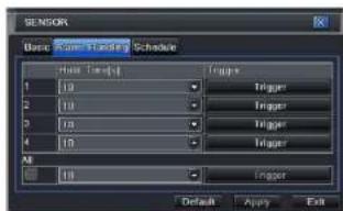
text_image
SENSOR Basic: Main Sequence Schedule Main Sequence Trigger 1 10 Trigger 2 10 Trigger 3 10 Trigger 4 10 Trigger All 10 Trigger Default Apply ExitPICTURE 8-4
Trigger: This is what the DVR will do once activated by an alarm. Selecting Setting will open a new window with three tabs; Alarm, To Record, To PTZ
Alarm allows you to set whether a buzzer will sound, which camera (if any) will display in full screen mode, whether an e-mail will be sent and whether a signal will be sent via the ALARM OUT port.
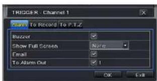
text_image
TRIGGER - Channel 1 Start To Record To P.T.Z Buzzer Show Full Screen None Email To Alarm Out 1 OK ExitPICTURE 8-5
To Record allows you to determine which cameras will begin recording. Cameras can be set to record individually, in blocks, or all cameras can be activated.
To PTZ activates preset, cruise or track functions on selected Pan-Tilt-Zoom cameras. Depending on your model of PTZ camera, one of up to 128 pre-set actions can be engaged. Check your camera's manual for details.
Schedule Tab
Set by default to always on, the schedule can be altered in the same manner as that used in
Schedule in SECTION 4.4.

text_image
Wave Mode Modulation Channel: 0 Timing: 00:00 04:00 08:00 12:00 16:00 20:00 Frequency: 0 Current: 0 Voltage: 0 Current: 0 Frequency: 0 Current: 0 Voltage: 0 Current: 0 Current: 0 Current: 0 Current: 0 Current: 0 Current: 0 Current: 0 Current: 0 Current: 0 Current: 0 Current: 0 Current: 0 Current: 0 Current: 0 Current: 0 Current: 0 Current: 0 Current: 0 Current: 0 Current: 0 Circuit Settings: 1.000 - Voltage - Power Circuit Settings: 1.000 - Current - LoadPICTURE 8-6
MOTION
Motion Tab
As with the Alarm function above, it incorporates hold time and can trigger procedures. Select which cameras you wish to start recording on motion detection. Set the holding time which determines the length of time the cameras continue recording after motion stops.
In the Trigger setting, you can set multiple channels to record when motion is detected by a camera that has been set to activate upon motion detection.
For example: If Camera 1 detects motion, you can have it trigger Cameras 2 and 3 to begin recording as well.
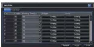
text_image
SETON Name: 100% Width: 100% Size: 100% Balance: 100% Balance: 100% Balance: 100% Balance: 100% Balance: 100% Balance: 100% Balance: 100% Balance: 100% Balance: 100% Balance: 100% Balance: 100% Balance: 100% Balance: 100% Balance: 100% Balance: -100% Balance: -100% Balance: -100% Balance: -100% Balance: -100% Balance: -100% Balance: -100% Balance: -100% Balance: -100% Balance: -100% Balance: -100% Balance: -100% Balance: -100% Balance: -100% Balance: -1 Balance: -1 Balance: -1 Balance: -1 Balance: -1 Balance: -1 Balance: -1 Balance: -1 Balance: -1 Balance: -1 Balance: -1 Balance: -1 Balance: -1 Balance: -1 Balance: -1 Balance: -1 Balance: -1 Balance: -1 Balance: -1 Balance: -1 Balance: -1PICTURE 8-7
In addition, the user can set the sensitivity of certain areas within the field of view by clicking on the Select button selecting the Area field for the respective camera.
Specific areas can be made sensitive by applying a blue grid to the desired section of the screen. The blue grid can be applied to the entire screen - signifying that the entire field of view is sensitive - by clicking on the star button. The trash can button will remove the grid completely. Click and drag with the mouse on the screen to draw or erase the grid in select areas.

natural_image
Close-up of a bird on a branch with blue grid overlay (no readable text or symbols)PICTURE 8-8
As sensitivity is influenced by color and light level, you can adjust its values according to your specific conditions. The default value is "4." A setting of "6" is most sensitive while a setting of "1" is minimally sensitive.
Right-clicking in the screen will show or hide the control menu at the bottom of the screen.
Test your settings by moving something or someone through the grid area in the camera's view. Motion should not be detected outside of this area but you should see a yellow humanoid figure appear in the screen once the DVR detects movement within the grid. Removing the grid where there is a flag or trees that frequently move in the wind will prevent false alerts. Click on the Disk button to save your settings before exiting the setup process by clicking on the X button.
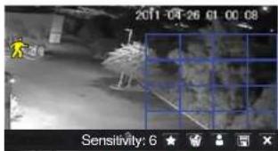
text_image
2011-04-26 01 00:08 Sensitivity: 6 ★PICTURE 8-9
Schedule Tab
This is also set to be on all the time by default and it can be adjusted in the same manner as the Schedule configuration in SECTION 4.4.
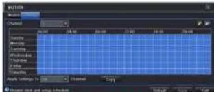
text_image
MOTION Motion Chamber 00:00 24:00 30:00 12:00 24:00 30:00 Motion Motion Chamber Chamber Chamber Chamber Chamber Auto Settings To: Chamber Copy Auto mode and setup parametersPICTURE 8-10
VIDEO LOSS
In the event that signal is lost by one camera, others can be activated to record while additional devices can also be triggered.
Like the Trigger tab in the Alarm Handling section of the Sensor menu, you can select the events that you wish to occur in the event that a video input is lost. Both Alarms and PTZ events can be scheduled as in the Sensor menu above.

text_image
VIDEO LOSS 1 Trigger 2 Trigger 3 Trigger 4 Trigger 5 Trigger 6 Trigger 7 Trigger 8 Trigger AS Trigger Default Apply ExitPICTURE 8-11
OTHER ALARM
In this menu you can set the DVR to alert you to a full Hard Drive, IP Conflict on the network or a Disconnection.
You can set the response as well as at what threshold of remaining disk space you wish to be alerted.
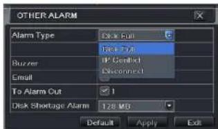
text_image
OTHER ALARM Alarm Type Disk Full Face Type Buzzer IP Conflict Email Disconnect To Alarm Out 1 Disk Shortage Alarm 128 MS Default Apply ExitPICTURE 8-12
ALARM OUT
Set how the alarms are handled and transmitted in this window. This controls any device attached to the ALARM OUT port on the back of the DVR. There are three tabs; Alarm Out, Schedule and Buzzer.
Alarm Out Tab
You can set the relay alarm out name as well as the hold time. Hold time is the interval between consecutive alarm activations so multiple events within the interval will not cause the alarm to sound again.

text_image
ALARM OUT Schedule Buzzer Delay Number [High Time S] 1 ALARM OUT 1 10 All 10 Default Apply ExitPICTURE 8-13
Schedule Tab
The default setting is for the ALARM OUT to be active all the time, but this can be changed to meet your particular requirements in a similar manner to Schedule in SECTION 4.4.
Buzzer Tab
As with the Alarm Out hold time, the internal buzzer can be enabled and given a hold time.
HARD DISK DRIVE
CHAPTER 9
Your DVR uses a standard desktop or 3.5" SATA (Serial Advanced Technology Attachment) hard disk drive and will support drives up to 2TB (terabytes). These drives are the current industry standard and may be purchased wherever computer parts are sold. Depending on where you purchased your DVR, your hard drive may already be installed. But, we recognize that you may wish to upgrade or replace your drive in the future so this DVR is designed to make installation and replacement easy for the average user. A 5400RPM drive will work but a 7200RPM drive is recommended for optimal performance.
It should be noted that while this is the only user-serviceable part within the case besides the battery and you will not void your warranty by installing or upgrading your hard disk drive, care must be taken to avoid damage to the other components within the case. Such damage will not be covered.

WARNING! ELECTRIC SHOCK RISK!
The DVR MUST be unplugged from all power sources as well as from the cameras before opening the case. Failure to do so can result in damage to the DVR or its components as well as injury or death.

9.1 INSTALLATION/REMOVAL
It is strongly advised against opening the case when atmospheric conditions present the risk of static discharge which can damage electronic components.
Whether installing the drive for the first time or removing the old one to install a new one, the steps are largely the same:
STEP 1. Disconnect the DVR from the power source as well as any other connections.
STEP 2. Remove screws (the number will vary depending on your model) from the side and rear of your DVR as indicated in Picture 9-1

text_image
Remove Screws VIAO 2017 VIAO 2018 VIDEO INPICTURE 9-1
STEP 3. Remove the case by sliding it backwards and then lifting off.
STEP 3A. If removing a hard drive, you will need to unscrew the four drive mounting screws at the bottom of the DVR or on the internal mounting rack.
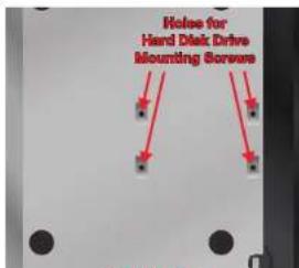
text_image
Hoise for Hand Disk Drive Mounting ScrewsPICTURE 9-2
STEP 4. Connect the power and data cables. Press firmly, but do not force them onto the pins or you may damage them. The connectors are "keyed" to ensure they are connected in the proper position.
STEP 5. Attach hard drive to the base of the DVR with screws using the four mounting holes.
STEP 6. Replace the DVR cover and secure.

text_image
HARD DRIVEMOUNTING HOLES DATA POWER FOR HARD DRIVE CABLE CABLE
PICTURE 9-3
9.2 CALCULATING THE RECORDING CAPACITY OF A HARD DRIVE
While the physical data capacity of a hard drive is fixed, how much video you can record upon it depends on your recording configurations. Higher quality recordings will take up more space on the drive and setting the DVR to record for more frequently will fill it up more rapidly.
To determine the optimal capacity for your purposes, the chart below to estimate the size of hard drive that you'll need.
| VIDEO FORMAT | RESOLUTION FRAME RATE (PPS) | VIDEO QUALITY | BIT RATE (bps) | SPACE USED (Mb/h) | |
| NTSC/PAL | CIF 30/25 Highest | 1000k 465 | |||
| Higher 768k 297 | |||||
| Medium 512k 230 | |||||
| Lower 256k 115 | |||||
| Lowest 128k 56 | |||||
| D1 | 30/25 | Highest | 2M | 912 | |
| Higher 1.5M | 512 | ||||
| Medium 1M | 468 | ||||
| Lower 768k 300 | |||||
| Lowest 512k 244 | |||||
| D1 | 7.5/6 | Highest | 500k | 228 | |
| Higher 375k 128 | |||||
| Medium 250k 117 | |||||
| Lower 192k 75 | |||||
| Lowest 128k 61 | |||||
| 1080P 30/25 Highest | 48M | 5400 | |||
| Higher | 36M | 4052 | |||
| Medium | 28M | 3152 | |||
| Lower | 16M | 1800 | |||
| Lowest | 6M | 676 | |||
| 7.5/6 | Highest | 12M | 1350 | ||
| Higher | 9M | 1013 | |||
| Medium 7M | 788 | ||||
| Lower | 4M | 450 | |||
| Lowest 1.5M | 169 | ||||
The formula for calculating the required disk space is:
Total Recording Capacity = Used space per hour (MB/h) x Recording time (hour) x number of channels
Example: A customer is using the NTSC format (30 frames per second), CIF resolution with video quality set to Lowest and a total of 16 Channels. He wants the unit to record continuously for a month. Therefore, the calculation will look like this:
56(MB/h), x 24 (hours/day) x 30 (days) x 16 (channels) = 645,120MB or 650GB
Installing a 750GB SATA hard drive should provide enough space for one month's continuous recording time at those settings.
APPENDIX
A.1 TROUBLESHOOTING
- The DVR does not start after connecting the power, what is wrong?
a. The power adapter may have been damaged, or is not providing enough power. Please change the adapter.
b. The DVR may not be getting enough power from the outlet or surge protector it is attached to.
c. There could be a problem with the system board on the DVR
- The indicator lights of the DVR are on, but no output. Why?
a. The power adapter may have been damaged, or is not providing enough power. Please change the adapter
b. The video format of the DVR is different from that of the monitor.
c. Connection problem. Please check the cable and the ports of the monitor and DVR.
- Why are no images displayed on some or all of the channels of the DVR?
a. Connection problem. Please check the cables and the ports of camera and DVR.
b. Camera problem. Please check the cameras by attaching them directly to TV or working port on DVR.
c. The video format (NTSC/PAL) of the DVR is different from that of the cameras. Please change DVR video format.
- The DVR cannot find the hard disk drive.
a. The power adapter is not providing enough power, or the adapter is not getting enough power from the outlet
b. Connection problem. Please check the power and data cables on the HDD.
c. The HDD is damaged and will need to be replaced.
- I cannot record, what could be the problem?
a. The HDD is not formatted. Please format it manually first.
b. The record function is not enabled or setup correctly. Please refer to Section 4.3
Record Configuration
c. The HDD is full and recycle function is not enabled. Please refer to Section 4.3 Record Configuration and the Recycle Record Tab in the Record Menu.
d. The HDD is damaged and will need to be replaced.
- I cannot use the mouse, what could be the problem?
a. Wait 5 minutes after connecting the mouse and then try again.
b. The mouse is not securely connected. Plug/unplug several times.
c. The mouse is incompatible with the system. Please try another mouse.
7 What can I do when the DVR starts and displays "please wait....."all the time?
a. First possible reason: hard drive power cable and/or data cable are not securely connected.
Solution: Please check the cable connections and make sure they are secure; if still not working, please unplug them and then plug them in again.
b. Second possible reason: The system is having problems reading the hard drive.
Solution: Try reformatting the current drive or re-placing it.
c. Solution: Try connecting the DVR to a different surge protector and power outlet.
- How do I input letters and numbers?
To input letters (such as passwords) and numbers click the box behind where text is to be entered, and then a small keyboard will appear. Please select number or letter to input (the default password is 123456), or you can use the digital keys on the front panel, or the digital keys on the remote control.

text_image
1 2 3 4 5 6 7 8 9 0 Backspace G W e r f v u i u p i l \ s s d f g h i k l . . Enter Shift z v c v b n m . . / EscPICTURE A-1
9. How do I upgrade the firmware on the DVR?
After you download the new firmware from the Q-See website at www.Q-See.com/Support and copy it onto a USB flash drive. Then select Upgrade in the menu.

WARNING! Do not turn the system power off during the upgrade process! Doing so may damage the chipset and prevent the DVR from starting.
10. I can get a live image on the display but I can't get the menu to display. How can I pull up the menu?
Hold down the ESC key to wait for login dialog box to appear.
- I hooked the DVR up to a TV through the BNC video out port and I do not see anything on the screen. How do I get the video to display?
By default the DVR is setup to use a VGA monitor, if you want to use a TV instead then push the ESC button on the front panel and hold it until you hear a beep, if you still do not get a display then hold the ESC button down again until you hear a beep, the display should come up. - What is the minimum configuration of a PC for remote connection?
| COMPONENT MINIMUM REQUIRED | |
| CPU Intel Coleron 2.4G | |
| MOTHERBOARD Intel 845 | |
| HDD 80G | |
| RAM 1GB | |
| VGA 512MB Video RAMNVIDIA GeForce MX440/FX5200ATIRADEON 7500/X300 | |
| OS | Windows XP(SP2 above) /VISTA/Win7 |
| DIRECTX | 9.0 |
- What are the PC configurations for 16-channel real time access with fully open mainstream channel?
| PC MODULE PARAMETERS | |
| CPU Intel Core(TM)2 Duo CPU E4800 | |
| MOTHERBOARD G41/P41 chip | |
| HDD 80G | |
| RAM 1GB | |
| VGA GMA3100/NVIDIA GeForce 8400/ATI RADEON HD3450, 512MB Video RAM | |
| OS Windows XP(SP2 above)/ VISTA/Win7, | |
| DIRECTX 9.0 | |
- On Vista and Win? I am getting an error message that Codec can't be installed or is missing, how do I solve that?
There are two ways to fix it:
a. In Windows, go to your Control Panel select User Account and Family Safety and then choose User Account Control.
Click Turn User Account On or Off. Uncheck the box next to Use User Account Control (UAC) to help protect your computer.
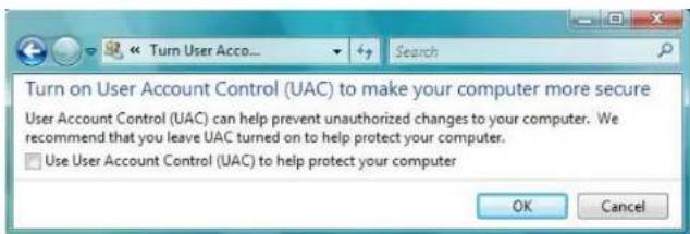
text_image
Turn on User Account Control (UAC) to make your computer more secure User Account Control (UAC) can help prevent unauthorized changes to your computer. We recommend that you leave UAC turned on to help protect your computer. Use User Account Control (UAC) to help protect your computerPICTURE A-2
b. Right-click on an Internet Explorer browser window. Select Run as Administrator to run browser.
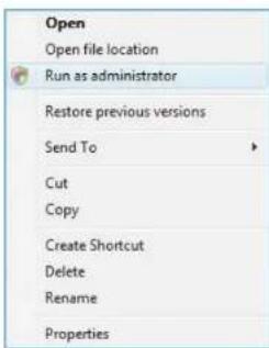
text_image
Open Open file location Run as administrator Restore previous versions Send To Cut Copy Create Shortcut Delete Rename PropertiesPICTURE A-3
A.2 SPECIFICATIONS
| Parameter QT228 QT2124 | ||||
| COMPRESSION | Format | Standard H.264 Baseline | ||
| VIDEO | Video In | Composite 1.0V p-p/75Ω, BNC x 8 | Composite 1.0V p-p/75Ω, BNC x 24 | |
| Video Out | COMPOSITE 1.0V p-p/75Ω, BNC x 1, VGA x 1, HDMI x 1 | COMPOSITE 1.0V p-p/75Ω, BNC x 2, VGA x 1 | ||
| VGA Resolution | 1280x1024, 1024x768, 800x600 | |||
| Record Resolution | NTSC: 352x240, 704x480PAL: 352x288, 704x576 | |||
| Display Frame Rate (per camera) | 704x480 at 30FPS | |||
| Record Frame Rate (per camera) | NTSC: CIF 30FPSPAL: CIF 25FPS | |||
| AUDIO Audio Input | -8dB - 22k | RCA X1 | -8dB - 22k, RCA X4 | |
| Audio Output | -8dB - 92dB, RCA X1 | |||
| ALARM | Alarm Input 0 | NO or NC 16CH | ||
| Alarm Output | 0 | 1CH | ||
| STORAGE | Record Mode | Manual/Sensor/Timer/Motion Detection | ||
| Multi-Function | Multiplex | |||
| INTERFACE | Network Interface | RJ45 (LAN, Internet) | ||
| Communication Interface | RS485, USB 2.0 x 2 (One for Backup, One for USB Mouse) | |||
| CONTROLS | PTZ Control | No | Yes | |
| Remote Control | Yes | |||
| DISK INFO | Disk Type | SATA x 2 (up to 2TB each) | SATA x 2 (up to 2TB each) | |
| OTHER INFO | Voltage | 12V3A | 12V5A | |
| Optimal Temperature | 50°F to 104°F 10°C to 40°C10% to 90% Humidity | |||
| Power Use w/o Hard Drive | 10W | 40W | ||
| Parameter | QT426 | QT428 | QT446 | |
| COMPRESSION | Format | Standard H.264 Baseline | ||
| VIDEO | Video In | Composite 1.0V p-p/75Ω, BNC x 16 | Composite 1.0V p-p/75Ω, BNC x 8 | Composite 1.0V p-p/75Ω, BNC x 4 |
| Video Out | COMPOSITE 1.0V p-p/75Ω, BNC x 2, VGA x 1 | COMPOSITE 1.0V p-p/75Ω, BNC x 1, VGA x 1 Loop Out x 2 | ||
| VGA Resolution | 1280x1024, 1024x768, 800x600 | |||
| Record Resolution | NTSC: 352x240, 704x480PAL: 352x288, 704x576 | |||
| Display Frame Rate (per camera) | 704x480 at 30FPS | |||
| Record Frame Rate (per camera) | NTSC: D1 7.5FPS CIF 30FPS PAL: D1 6.25FPS CIF 25FPS | |||
| AUDIO | Audio Input | -8dB-22k, RCA X1 | -8dB-22k, RCA X16 | |
| Audio Output | -8dB-92dB, RCA X1 | -8dB-92dB, RCA X1 | ||
| ALARM | Alarm Input | NO or NC 8CH | NO or NC 18CH | NO or NC 18CH |
| Alarm Output | 1CH | |||
| STORAGE | Record Mode | Manual/Sensor/Timer/Motion Detection | ||
| Multi-Function | Multiplex | |||
| INTERFACE | Network Interface | RJ45 (LAN, Internet) | ||
| Communication Interface | RS485, USB 2.0 x 2 (One for Backup, One for USB Mouse) | eSATA x2 RS485, USB 2.0 x 2 (One for Backup, One for USB Mouse) | ||
| CONTROLS | PTZ Control | Yes | ||
| Remote Control | Yes | |||
| DISK INFO | Disk Type | SATA x 1 (up to 2TB) | SATA x 4 (up to 2TB each) | |
| OTHER INFO | Voltage | 12V3A | 12V4A 110/220 | |
| Optimal Temperature | 50°F to 104°F 10°C to 40°C10% to 90% Humidity | |||
| Power Use w/o Hard Drive | 10W | 20W | 22W | |
| Parameter QT454 QT474 QT4332 | |||||
| COMPRESSION Format Standard H.264 Baseline | |||||
| VIDEO Video In Composite 1.0V p-p/75Ω, BNC x 4 | Composite 1.0V p-p/75Ω, BNC x 32 | ||||
| Video Out COMP | OSITE1.0V p-p/75Ω, BNC x 2, VGA x 1 | COMPOSITE1.0V p-p/75Ω, BNC x 1, VGA x 1 | COMPOSITE1.0V p-p/75Ω, BNC x 1, VGA x 1, HDMI x 1 | ||
| VGA Resolution | 1280x1024, 1024x768, 800x600 19 | 20x10801280x1024, 1024x768, 800x600 | |||
| Record Resolution | NTSC: 352x240, 704x480PAL: 352x268, 704x576 | ||||
| Display Frame Rate(per camera) | 704x480 at 30FPS | ||||
| Record Frame Rate(per camera) | NTSC: D1 7.5FPS CIF 30FPSPAL: D1 6.25FPS CIF 25FPS | NTSC: D1 7.5FPS CIF 30FPS4CH D1 30FPS II others CIFPAL: D1 6.25FPS CIF 25FPS | |||
| AUDIO Audio Input -8dB- 22k, | RCA X4 | -8dB- 22k, RCA X2 | -8dB- 22k, RCA X16 | ||
| Audio Output -8dB-92dB, RCA X1 | |||||
| ALARM Alarm Input NO or NC 4CH 0 NO or NC 16CH | |||||
| Alarm Output 1CH 0 | 4CH | ||||
| STORAGE | Record Mode | Manual/Sensor/Timer/Motion Detection | |||
| Multi-Function | Multiplex | ||||
| INTERFACE Network Interface | RJ45 (LAN, Internet) | ||||
| Communication Interface | RS485,USB 2.0 x 2 (One for Backup, One for USB Mouse) | eSATA x2RS485,USB 2.0 x 2(One for Backup, One for USB Mouse) | |||
| CONTROLS | PTZ Control | Yes | |||
| Remote Control | Yes | ||||
| DISK INFO | Disk Type | SATA x 1 (up to 2TB) | SATA x 4 (up to 2TB each) | ||
| OTHER INFO | Voltage | 12V3A | 12V3A | 110/220 | |
| Optimal Temperature | 50°F to 104°F 10°C to 40°C10% to 90% Humidity | ||||
| Power Use w/o Hard Drive | 10W | 10W | 42W | ||
| Parameter | QT4532 QT4516 QT4760 | ||||
| COMPRESSION | Compression Format | Standard H.264 Baseline | |||
| VIDEO | Video In | Composite 1.0V p-p/75Ω, BNC x 32 | Composite 1.0V p-p/75Ω, BNC x 16 | ||
| Video Out | COMPOSITE 1.0V p-p/75Ω, BNC x 1, VGA x 1, HDMI x 1 | COMPOSITE 1.0V p-p/75Ω, BNC x 2, VGA x 1, HDMI x 1 | |||
| VGA Resolution | 1920x1050 1280x1024, 1024x768, 800x600 | 1280x1024, 1024x768, 800x600, HDMI | |||
| Record Resolution | NTSC: 352x240, 704x480PAL: 352x288, 704x576 | ||||
| Display Frame Rate (per camera) | 704x480 at 30FPS | ||||
| Record Frame Rate (per camera) | NTSC: D1 7.5FPS CIF 30FPS 4CH D1 30FPS if others CIF PAL: D1 6.25FPS CIF 25FPS | NTSC: 30FPS PAL: 25FPS | |||
| AUDIO | Audio Input | -8dB- 22k, RCA X16 | -8dB- 22k, RCA X4 | ||
| Audio Output | -8dB-92dB, RCA X1 | ||||
| ALARM | Alarm Input | NO or NC 16CH | |||
| Alarm Output | 4CH | 1CH | |||
| STORAGE | Record Mode | Manual/Sensor/Timer/Motion Detection | |||
| Multi-Function | Multiplex | ||||
| INTERFACE Network Interface | RJ45 (LAN, Internet) | ||||
| Communication Interface | eSATA x2RS485, USB 2.0 x 2 (One for Backup, One for USB Mouse) | RS485, USB 2.0 x 2 (One for Backup, One for USB Mouse) | |||
| CONTROLS | PTZ Control | Yes | |||
| Remote Control | Yes | ||||
| DISK INFO | Disk Type | SATA x 8 (up to 2TB each) | SATA x 1 (up to 2TB each) | SATA x 2 (up to 3TB each) | |
| OTHER INFO | Voltage | 110/220 | 12V3A | ||
| Optimal Temperature | 50°F to 104°F 10°C to 40°C10% to 90% Humidity | ||||
| Power Use w/o Hard Drive | 42W | 20W | 18W | ||
| Parameter QT504 QT528 QT526 | |||||||
| COMPRESSION | Compression Format | Standard H.264 Baseline | |||||
| VIDEO Video In Composite 1.0V | p-p/75Ω, BNC x 4 | Composite 1.0V p-p/75Ω, BNC x 8 | Composite 1.0V p-p/75Ω, BNC x 16 | ||||
| Video Out COMPOSITE 1.0V p-p/75Ω, BNC x 2, VGA x 1 | |||||||
| VGA Resolution | 1280x1024, 1024x768, 800x600 | ||||||
| Record Resolution | NTSC: 352x240, 704x480PAL: 352x288, 704x576 | ||||||
| Display Frame Rate(per camera) | 704x480 at 30FPS | ||||||
| Record Frame Rate(per camera) | NTSC: D1 30FPS CIF 30FPSPAL: D1 25FPS CIF 25FPS | ||||||
| AUDIO Audio Input -8dB~ 22k, RCA X4 | |||||||
| Audio Output -8dB-92dB, RCA X1 | |||||||
| ALARM Alarm Input NO or NC 4CH NO or NC 8CH NO or NC | 16CH | ||||||
| Alarm Output 1CH | |||||||
| FUNCTION Record Mode Manual/Sensor/Timer/Motion Detection | |||||||
| Multi-Function | Simultaneously Record, View Live or Recorded Video, Playback, Back-up files, Monitor Remotely | ||||||
| INTERFACE | Network Interface | RJ45 (LAN, Internet) | |||||
| Communication Interface | RS485, USB 2.0 x 2 (One for Backup, One for USB Mouse) | ||||||
| CONTROLS | PTZ Control | Yes | |||||
| Remote Control | Yes | ||||||
| DISK INFO | Disk Type | SATA x 1 (up to 2TB each) | SATA x 2 (up to 2TB each) | ||||
| OTHER INFO | Voltage | 12V3A | 12V4A | 12V5A | |||
| Optimal Temperature | 32°F to 122°F 10°C to 50°C10% to 90% Humidity | ||||||
| Power Use w/o Hard Drive | 10W | 18W | 30W | ||||
| Parameter QT518 QT5116 QT536 | |||||||
| COMPRESSION Compression Format | Standard H.264 Baseline | ||||||
| VIDEO Video In Composite 1.0V | p-p/75Ω, BNC x 8 | Composite 1.0V p-p/75Ω, BNC x 16 | Composite 1.0V p-p/75Ω, BNC x 16 | ||||
| Video Out COMPOSITE 1.0V p-p/75Ω, BNC x 2, VGA x 1, HDMI, Loopout x 8 | COMPOSITE 1.0V p-p/75Ω, BNC x 2, VGA x 1, HDMI, | COMPOSITE 1.0V p-p/75Ω, BNC x 2, VGA x 1, HDMI, Loopout x 16 | |||||
| VGA Resolution | 1920x1080, 1280x1024, 1024x768, 800x800 | ||||||
| Record Resolution | NTSC: 352x240, 704x480PAL: 352x288, 704x576 | ||||||
| Display Frame Rate (per camera) | 704x480 at 30FPS | ||||||
| Record Frame Rate (per camera) | NTSC: D1 30FPS CIF 30FPSPAL: D1 25FPS CIF 25FPS | ||||||
| AUDIO Audio Input -8dB~ 22k | RCA X8 | -8dB~ 22k, RCA X16 | -8dB~ 22k, RCA X16 | ||||
| Audio Output -8dB~92dB, RCA X4 | -8dB~92dB, RCA X1 | ||||||
| ALARM | Alarm Input | NO or NC 8CH | NO or NC 16CH | NO or NC 16CH | |||
| Alarm Output 4CH | 4CH | 4CH | |||||
| FUNCTION | Record Mode | Manual/Sensor/Timer/Motion Detection | |||||
| Multi Function | Simultaneously Record, View Live or Recorded Video, Playback, Back-up Iles, Monitor Remotely | ||||||
| INTERFACE Network Interface | RJ45 (LAN, Internet) | ||||||
| Communication Interface | RS485, eSATA, Microphone USB 2.0 x 2 (One for Backup, One for USB Mouse) | RS485, eSATA x 2, Microphone USB 2.0 x 2 (One for Backup, One for USB Mouse) | |||||
| CONTROLS | PTZ Control | Yes | |||||
| Remote Control | Yes | ||||||
| DISK INFO | Disk Type | SATA x 3 (up to 2TB each) | SATA x 8 (up to 2TB each) | ||||
| OTHER INFO | Voltage | 110/230V | |||||
| Optimal Temperature | 50°F to 104°F 10°C to 40°C10% to 90% Humidity | ||||||
| Power Use w/o Hard Drive | 22W | 36W | 50W | ||||
| Parameter QT548 QT578 QT5024 | ||||
| COMPRESSION Compression Format | Standard H.264 Baseline | |||
| VIDEO Video In Composite 1.0V p-p/75Ω, BNC x 8 | Composite 1.0V p-p/75Ω, BNC x 24 | |||
| Parameter QT5032 QT5132 QT5140 | ||||
| COMPRESSION Compression Format | Standard H.264 Baseline | |||
| VIDEO Video In Composite 1.0V | p-p/75Ω,BNC x 32 | Composite 1.0Vp-p/75Ω,BNC x 32 | Composite 1.0Vp-p/75Ω,BNC x 4 | |
| Video Out COMPOSITE 1.0V p-p/75Ω, BNC x 1, VGA x 1, HDMI x 1 | ||||
| VGA Resolution 1280x1024, 1024x768, 800x600, HDMI | ||||
| Record Resolution NTSC:352x240,704x480960x480 (960H)PAL: 352x268,704x576960x576 (960H) | NTSC: 352x240, 704x480PAL: 352x288, 704x576 | |||
| Display Frame Rate(per camera) 704x480 at 30FPS | ||||
| Record Frame Rate(per camera) NTSC:960H & D1 30FPS CIF 30FPSPAL:960H & D125FPS CIF25FPS | NTSC:D1 30 FPS CIF30FPSPAL:D1 25FPS CIF25FPS | NTSC:960H & D1 30FPS CIF 30FPSPAL:960H & D125FPS CIF25FPS | ||
| AUDIO Audio Input -8dB- 22k, | RCA X16 | -8dB- 22k, RCA X4 | -8dB- 22k,RCA X2 | |
| Audio Output -8dB-92dB, RCA XI | ||||
| ALARM Alarm Input NO or NC 16CH | None | |||
| Alarm Output 4CH 1CH None | ||||
| STORAGE Record Mode Manual/Sensor/Timer/Motion Detection | ||||
| Multi-Function Multiplex | ||||
| INTERFACE Network Interface | PJ45 (LAN, Internet) | |||
| Communication Interface eSATA x2RS485,USB 2.0 x 2(One for Backup, Onefor USB Mouse) | RS485,USB 2.0 x 2 (One for Backup, Onefor USB Mouse) | |||
| CONTROLS | PTZ Control Yes | |||
| Remote Control Yes | ||||
| DISK INFO | Disk Type SATA x 8 (up to3TB each) | SATA x 2 (up to3TB each) | SATA x 1 (up to2TB each) | |
| OTHER INFO | Voltage 110/230V | 12V4A | 12V2A | |
| Optimal Temperature 50°F to 104°F 10°C to 40°C10% to 90% Humidity | ||||
| Power Use w/o Hard Drive 42W | 40W | 5W | ||
| Parameter QT5440 QT5516 QT5616 | ||||
| COMPRESSION Compression Format | Standard H.264 Baseline | |||
| VIDEO Video In Composite 1.0V | p-p/75Ω, BNC x 4 | Composite 1.0V p-p/75Ω, BNC x 16 | ||
| Video Out COMPOSITE 1.0V p-p/75Ω, BNC x 2, VGA x 1, HDMI x 1 | ||||
| VGA Resolution | 1280x1024, 1024x768, 800x600, HDMI | |||
| Record Resolution | NTSC:352x240,704x480PAL:352x288,704x576 | NTSC:352x240,704x480960x480 (960H)PAL:352x288,704x576960x576 (960H) | ||
| Display Frame Rate(per camera) | 704x480 at 30FPS | |||
| Record Frame Rate(per camera) | NTSC:960H & D1 30FPS CIF 30FPSPAL:960H & D125FPS CIF25FPS | NTSC:30FPS PAL:25FPS | ||
| AUDIO Audio Input -8dB- 22k, | RCA X2 | -8dB- 22k, RCA X4 | ||
| Audio Output -8dB-92dB, RCA X1 | ||||
| ALARM Alarm Input None NO or NC | 16CH | |||
| Alarm Output None 1CH | ||||
| STORAGE Record Mode Manual/Sensor/Timer/Motion Detection | ||||
| Multi-Function | Multiplex | |||
| INTERFACE Network Interface | RJ45 (LAN, Internet) | |||
| Communication Interface | RS485,USB 2.0 x 2 (One for Backup, One for USB Mouse) | |||
| CONTROLS | PTZ Control | Yes | ||
| Remote Control | Yes | |||
| DISK INFO | Disk Type | SATA x 1 (up to 2TB each) | SATA x 1 (up to 3TB each) | |
| OTHER INFO | Voltage | 12V2A | 12V3A | |
| Optimal Temperature | 50°F to 104°F 10°C to 40°C10% to 90% Humidity | |||
| Power Use w/o Hard Drive | 5W | 18W | ||
| Parameter QT5680 QQT5682 | ||||
| COMPRESSION Compression Format | Standard H.264 Baseline | |||
| VIDEO Video In Composite 1.0V p-p/75Ω, BNC x 8 | ||||
| Video Out COMPOSITE 1.0V p-p/75Ω, BNC x 1, VGA x 1, HDMI x 1 | ||||
| VGA Resolution | 1280x1024, 1024x768, 800x600, HDMI | |||
| Record Resolution | NTSC:352x240,704x480PAL:352x288,704x576 | NTSC:352x240,704x480976x494PAL:352x288,704x576976x552 | ||
| Display Frame Rate (per camera) | 704x480 at 30FPS | |||
| Record Frame Rate (per camera) | NTSC:D1 30 FPSCIF 30FPSPAL:D1 25FPSCIF 25FPS | NTSC:960H 30 FPSD1 30 FPSCIF 30FPSPAL:960H 30 FPSD1 25FPSCIF 25FPS | ||
| AUDIO Audio Input -8dB- 22k, RCA X2 | ||||
| Audio Output -8dB-92dB, RCA X1 | ||||
| ALARM Alarm Input None | ||||
| Alarm Output None | ||||
| STORAGE Record Mode Manual/Sensor/Timer/Motion Detection | ||||
| Multi-Function Multiplex | ||||
| INTERFACE Network Interface | RJ45 (LAN, Internet) | |||
| Communication Interface | RS485,USB 2.0 x 2 (One for Backup, One for USB Mouse) | |||
| CONTROLS | PTZ Control | Yes | ||
| Remote Control | Yes | |||
| DISK INFO | Disk Type | SATA x 1 (up to 3TB each) | ||
| OTHER INFO | Voltage | 12V2A | 12V2A | |
| Optimal Temperature | 50°F to 104°F 10°C to 40°C10% to 90% Humidity | |||
| Power Use w/o Hard Drive | 5W | 5W | ||
| Parameter QT5716 QT534 | |||||||
| COMPRESSION Compression Format | Standard H.264 Baseline | ||||||
| VIDEO Video In Composite 1.0V | p-p/75Ω, BNC x 16 | Composite 1.0V p-p/75Ω, BNC x 4 | |||||
| Video Out COMPOSITE 1.0V p-p/75Ω, BNC x 1, VGA x 1, HDMI x 1 | |||||||
| VGA Resolution | 1280x1024, 1024x768, 800x600, HDMI | ||||||
| Record Resolution | NTSC: 352x240, 704x480 PAL: 352x288, 704x576 | ||||||
| Display Frame Rate (per camera) | 704x480 at 30FPS | ||||||
| Record Frame Rate (per camera) | NTSC: D1 30 FPS CIF 30FPS PAL: D1 25FPS CIF 25FPS | ||||||
| AUDIO Audio Input -8dB~ 22k, | RCA X2 | -8dB~ 22k, RCA X1 | |||||
| Audio Output -8dB~92dB, RCA X1 | |||||||
| ALARM Alarm Input None | |||||||
| Alarm Output None | |||||||
| STORAGE Record Mode Manual/Sensor/Timer/Motion Detection | |||||||
| Multi-Function Multiplex | |||||||
| INTERFACE Network Interface | RJ45 (LAN, Internet) | ||||||
| Communication Interface | RS485, USB 2.0 x 2 (One for Backup, One for USB Mouse) | RS485, USB 2.0 x 2 (One for Backup, One for USB Mouse) | |||||
| CONTROLS | PTZ Control | Yes | No | ||||
| Remote Control | Yes | No | |||||
| DISK INFO | Disk Type | SATA x 1 (up to 3TB each) | |||||
| OTHER INFO | Voltage | 12V3A | 12V2A | ||||
| Optimal Temperature | 50°F to 104°F 10°C to 40°C 10% to 90% Humidity | ||||||
| Power Use w/o Hard Drive | 8W | 5W | |||||
| Parameter QT704 Q714 QT718 | |||||||
| COMPRESSION Compression Format | Standard H.264 Baseline | ||||||
| VIDEO Video In SDI x 4 SDI x 8 | |||||||
| Video Out COMPOSITE 1.0V p-p/75Ω, BNC x 1, VGA x 1, HDMI x 1 | |||||||
| VGA Resolution | 1280x1024, 1024x768, 800x600, HDMI, 1080P | ||||||
| Record Resolution | 1080P | ||||||
| Display Frame Rate (per camera) | 1080P at 30FPS | ||||||
| Record Frame Rate (per camera) | NTSC: 7FPS PAL: 6FPS | NTSC: 30FPS PAL: 25FPS | |||||
| AUDIO Audio Input -8dB~ 22k, RCA X4 -8dB~ 22k, RCA X8 | |||||||
| Audio Output -8dB~82dB, RCA X1 | |||||||
| ALARM Alarm Input NO or NC 4CH | NO or NC 8CH | ||||||
| Alarm Output | 1CH | ||||||
| STORAGE | Record Mode | Manual/Sensor/Timer/Motion Detection | |||||
| Multi-Function | Multiplex | ||||||
| INTERFACE Network Interface | RJ45 (LAN, Internet) | ||||||
| Communication Interface | RS485, USB 2.0 x 2 (One for Backup, One for USB Mouse), cSATA | ||||||
| CONTROLS | PTZ Control | Yes | |||||
| Remote Control | Yes | ||||||
| DISK INFO | Disk Type | SATA x 3 (up to 3TB each) | SATA x 2 (up to 3TB each) | ||||
| OTHER INFO | Voltage | 12V5A 12V5A | |||||
| Optimal Temperature | 50°F to 104°F 10°C to 40°C 10% to 90% Humidity | ||||||
| Power Use w/o Hard Drive | 1CW | ||||||
| Parameter QT7116 QT724 QT728 | ||||
| COMPRESSION Compression Format | Standard H.264 Baseline | |||
| VIDEO Video In SDI x 16 SDI x 4 SDI x 8 | ||||
| Video Out COMPOSITE 1.0V p-p/75Ω, BNC x 1, VGA x 1, HDMI x 1 | ||||
| VGA Resolution 1280x1024, 1024x768, 800x600, HDMI, 1080P | ||||
| Record Resolution | 1080P 720P | |||
| Display Frame Rate(per camera) | 1080P at 30FPS | 720P at 30FPS | ||
| Record Frame Rate(per camera) | NTSC: 15FPSPAL: 12FPS | NTSC: 30FPS PAL: 25FPS | ||
| AUDIO Audio Input -8dB~ 22k, | -8dB~ 22k,RCA X4 | -8dB~ 22k,RCA X8 | ||
| Audio Output -8dB~92dB, RCA X1 | ||||
| ALARM Alarm Input NO or NC | 16CH | NO or NC 4CH | NO or NC 8CH | |
| Alarm Output | 4CH | 1CH | ||
| STORAGE | Record Mode | Manual/Sensor/Timer/Motion Detection | ||
| Multi-Function | Multiplex | |||
| INTERFACE Network Interface | RJ45 (LAN, Internet) | |||
| Communication Interface | RS465,USB 2.0 x 2 (One for Backup, One for USB Mouse),eSATA | |||
| CONTROLS | PTZ Control | Yes | ||
| Remote Control | Yes | |||
| DISK INFO | Disk Type | SATA x 8 (up to 3TB each) | SATA x 1 (up to 3TB each) | |
| OTHER INFO | Voltage | 110/230V | 12V | |
| Optimal Temperature | 50°F to 104°F 10°C to 40°C10% to 90% Humidity | |||
| Power Use w/o Hard Drive | 40W | 20W | ||
A.3 RACK MOUNTING
The QT446, QT4332, QT4532, QT518, QT5116 and QT536 all use 2U cases and include brackets and screws allowing them to be secured in a standard server rack or server cabinet. These DVRs are designed for horizontal mounting only.
The DVR must rest on a shelf sufficient to hold its weight. The included mounting brackets are only intended to keep the system from shifting and they are not sufficient to suspend the DVR alone. You will also need to provide bolts to attach the brackets to the rack.
Two mounting brackets and four screws are contained in the accessory box that accompanied your DVR. Some brackets will have three holes but only two screws are required to mount the bracket to the DVR.

natural_image
Two metal bracket components with mounting holes and small bolts (no text or symbols visible)The flanges to secure the DVR to the rack should be towards the front.
natural_image
Close-up of a black electronic device with control panel and mounting bracket (no visible text or symbols)The DVR must have sufficient support when installed. The brackets are only to keep the DVR from moving. Ensure that all four holes on the two mounting brackets line up with holes in the rack.
If you will have limited access to the back of the DVR, it is best to make sure that all cameras and other cable connections on the back of the DVR are secure before bolting the brackets to the rack.
text_image
HDD SEARCH PF STOPQ-SEE PRODUCT WARRANTY
Q-See is proud to back all of our products with a conditional service warranty covering all hardware for 12 months from the date of purchase. Additionally, our products also come with a free exchange policy that covers all manufacturing defects for one month from the date of purchase. Permanent upgrading service is provided for the software.
Liability Exclusions:
Any product malfunction or abnormalities in operation or damage caused by the following reasons are not within the free service scope of our company:
- Equipment damage caused by improper operation.
- Improper equipment operation environment and conditions (e.g., improper power, extreme environmental temperatures, humidity, lightning and sudden surges of electricity).
- Damage caused by acts of nature (e.g., earthquake, fire, etc).
- Equipment damage caused by the maintenance of personnel not authorized by Q-See.
- Product sold over 12 months ago.
In order to fulfill the terms of your warranty, you must complete the registration process after purchasing our product. To do this, simply fill out the User's Information Card on our website at www.Q-See.com

QUESTIONS OR COMMENTS? CONTACT US
PRODUCT SUPPORT, DOWNLOADS, FIRMWARE UPDATES & MANUALS
24/7 Technical Resources
Live Chat (M-F, 9-5 PST)
www.Q-See.com/Support
