Octavia Tour (2005) - Automotive SKODA - Free user manual and instructions
Find the device manual for free Octavia Tour (2005) SKODA in PDF.

| Product Type | Compact car |
| Brand | Skoda |
| Model | Octavia Tour (2005) |
| Engine Options | 1.4L, 1.6L, 1.8L, 2.0L petrol; 1.9L TDI diesel |
| Fuel Type | Petrol or diesel |
| Transmission | 5-speed manual or 4-speed automatic |
| Length | 4,572 mm |
| Width | 1,760 mm |
| Height | 1,460 mm |
| Wheelbase | 2,512 mm |
| Curb Weight | Approximately 1,300 kg |
| Fuel Tank Capacity | 55 liters |
| Fuel Consumption (combined) | 7-8 L/100 km (petrol); 5-6 L/100 km (diesel) |
| Safety Features | Front airbags, ABS, side impact protection |
| Maintenance Interval | Every 15,000 km or annually |
| Recommended Oil | 5W-30 or 5W-40 (VW 502.00/505.00) |
| Coolant Type | G12+ (pink) |
| Brake Fluid Change | Every 2 years |
| Spare Parts Availability | Widely available from OEM and aftermarket |
| Reparability | Moderate; DIY-friendly for common repairs |
Frequently Asked Questions - Octavia Tour (2005) SKODA
User questions about Octavia Tour (2005) SKODA
0 question about this device. Answer the ones you know or ask your own.
Ask a new question about this device
Download the instructions for your Automotive in PDF format for free! Find your manual Octavia Tour (2005) - SKODA and take your electronic device back in hand. On this page are published all the documents necessary for the use of your device. Octavia Tour (2005) by SKODA.
USER MANUAL Octavia Tour (2005) SKODA
You have opted for a Škoda, sincere thanks for your confidence.
Your Škoda has proven to be a successful car for all-round use.
Functionality, customer satisfaction and environmental protection aspects played an important part in its design, the selection of materials used and manufacture.
The results speak for themselves.
Your Škoda is extremely economic when it comes to fuel consumption, has a low pollution level, needs only a small amount of servicing at long intervals and has durable wearing parts.
Your Škoda thus has all the virtues typical for a modern car such as good motoring economy, quality, reliability and long-time retention of its value.
An efficient service organisation is available for looking after your Škoda: in Europe alone, the service network already comprises more than 2500 Škoda Dealers that work economically and professionally in accordance with factory guidelines.
These Škoda Dealers are also committed to ensure that your Škoda is always in proper condition.
A requirement for warranting repairs free of charge is that the Service Inspections (see Service Schedule) and repairs during the warranty period have been carried out by an authorized Škoda Dealer.
Warranty claims are void if the damage to the vehicle has been caused by parts and accessories not approved by the manufacturer Škoda Auto, or by failure to observe maintenance and repair instructions.
Your Škoda Dealers will gladly supply details of the aforementioned services and possible differences in specific countries. Please also refer to the information in the Service Schedule.
We wish you pleasant motoring at all times.
Your Škoda Auto
TABLE OF CONTENTS
CONTROLS AND EQUIPMENT
Keys 6
Electronic immobiliser 7
Locking....8
Storage compartments 10
Tailgate.... 11
Remote control* 12
Anti-theft alarm system* 13
Power windows* 15
Rear-view mirrors 16
Head restraints.... 18
Front seats 19
Electrically operated seat* 20
Rear seat 25
Luggage compartment cover 26
Luggage compartment 27
Luggage compartment cover (Estate) .. 32
Raised luggage area* (Estate).... 32
Net partition Estate* 33
Pedals 35
Handbrake 36
Armrest ^* 36
Mobile phone, hands-free system* ..... 37
Manual gearbox 38
Automatic gearbox* 39
Adjustable steering column 43
Ignition lock 43
Starting engine 44
Switching off engine 46
Audible signals 46
Audible signal when reversing*...... 47
Excess speed signal* 47
Instruments 48
Navigation system* 55
Indicator/warning lights 56
Switches 62
Tempomat (cruise control system)* ..... 68
Multifunction steering wheel* 70
Windscreen wiper and washer system .. 71
Heating and ventilation 72
Air conditioning* 75
Climatronic (automatic air
conditioning)* 79
Electric sliding/tilting roof* 85
Sun visors 86
Storage compartment on the front
passenger side 87
Beverage holder* 87
Interior lights 87
Cigarette lighter, socket 89
Ashtrays 90
Note holder* 91
Note holder 91
Roof rack* 91
SAFETY
Basic information 93
Correct seated position 94
Seat belts 98
Airbag system* 103
Child safety 111
DRIVING TIPS
The first 1500 kilometres
(1000 miles) - and after 117
Driving economically while protecting
the environment 118
Brakes 120
All-wheel drive* 123
Towing a trailer 124
GENERAL MAINTENANCE
Filling the tank 127
Fuel 128
Care of car 129
Bonnet 135
LongLife Service* 138
Specification 138
Power steering 141
Cooling system 142
Brake fluid 144
Battery 146
Spark plugs 150
Ribbed belt 150
Windscreen washer system 151
Windscreen wiper blades 151
Dust and pollen filter* 152
Wheels 153
Motoring abroad 158
Mobile phones and two-way radios .... 159
Accessories, modifications and parts .. 159
Technical changes 160
DO-IT-YOURSELF
First-aid box, warning triangle.... 161
Car tool kit 161
Tyre repair spray* 162
Tyre repair set* 162
Spare wheel 162
Changing a wheel 163
Anti-theft lock of wheels* 166
Fire extinguisher* 166
Fuses 167
Replacing a bulb 169
Jump-starting 177
Tow-starting/towing 178
TECHNICAL DATA
Vehicle identification data 181
DOCUMENTATION
The documentation of your car includes in addition to this „Owner’s Manual“, a „Service Schedule“, „Assistance in Europe“, „Technical Data“ and all other instructions related to the operation of the vehicle.
Moreover, other Instructions and Supplementary Instructions may be provided depending on the vehicle type and equipment (e.g. operating instructions for the radio). If you find that some of this printed material is missing or if you believe that the information on some types of equipment or model versions are incomplete or differ, please contact your Škoda Dealer immediately. Your dealer will assist you in every possible way.
Please note that the information stated in the vehicle registration documents always takes precedence over the information contained in the Owner's Manual.
Refer to the technical documentation of the vehicle or to the supplement to the Owner's Manual for the technical data of your vehicle.
This Owner's Manual
and the additional instructions are publications which you should read attentively as soon as possible so that you become familiar with your car.
This Owner's Manual describes the current scope of equipment. Certain items of equipment listed are only installed later on and only envisaged for particular markets. The illustrations can differ in minor details from your vehicle; they are only intended for general information. Please pay particular attention to the section on "Driving Tips" in this Owner's Manual: there you can find how you can drive safely, economically and in an environmentally conscious way.
For safety reasons, please also pay attention to the information on Accessories, Modifications and Replacement of Parts on page 159.
The other chapters are also important, however, for proper treatment of your car - in addition to regular care and maintenance - helps to retain its value and in many cases is also one of the requirements for warranty claims.
The Service Schedule
contains:
- identification data of your car,
- the service intervals,
- the service inspection to be carried out and the mobility warranty are confirmed.
- the service work,
- information on the warranty.
The service work carried out is also confirmed in the Service Schedule, this being a requirement for any claims under the warranty.
Please always present the Service Schedule when you take your car to a Škoda Dealer. In the event of loss, theft and invalidation of the Service Schedule, please contact your Škoda Dealer where your vehicle is regularly serviced. You will receive a duplicate in which your Dealer has entered all the information regarding previously carried out services.
Assistance in Europe
contains addresses and telephone numbers of the Škoda Importer.
Technical data
contain important information regarding the vehicle.
Notes on the layout of this Manual:
This Manual describes to the maximum possible extent the current engineering and range of equipment of your car at the time of going to press. Certain equipment may only be available after a certain delay or not at all, or is offered only in certain export countries.
Equipment marked with * is fitted as standard only to certain model versions or is available only for certain models as optional equipment.
Texts with the heading „Warning“ and with this background colour, refer to the risks of possible accidents and injuries.

Texts marked with this symbol and written in italic are important environmental protection information.
One more request in conclusion:
If you sell your car, please hand over the complete documentation to the new owner for the documentation belongs in the car!
CONTROLS AND EQUIPMENT
General view

text_image
1 2 3 4 5 6 7 8 9 10 11 12 13 14 15 16 17 18 19 20 21 22 23 24 25 26| Page | ||
| 1 Exterior mirrors adjustable from inside* 17 | ||
| 2 Air vents 73, 76, 83 | ||
| 3 | Lever for the multi-functional switch:low beam, headlight flasher and cruise control* | 67, 68Tur |
| 4 | Instrument cluster:Instruments and warning lights | 48, 56 |
| 5 | Lever for windscreen wiper/ washer with switch for multifunction display | 50, 71 |
| 6 Switch for heated rear window 63 | ||
| 7 Switch for ESP/TCS* 63 | ||
| 8 Switch for hazard warning light system 63 | ||
| 9 Thumbwheel for seat heater* 65 | ||
| 10 | Remote fuel filler flap release from driver's seat* | 65 |
| 11 Passenger airbag 103 | ||
| 12 Storage compartment in the front doors - | ||
| 13 | Button for central locking and electrical power windows | 8, 15 |
| 14 Remote bonnet release 135 | ||
| 15 | Switch for parking light, low beam, rear fog 62 lightand instrument lighting | 66 |
| Page | ||
| 16 | Storage compartment below the steering wheel | - |
| 17 | Horn, driver airbag* | 103 |
| 18 | Lever for adjusting height of steering column lights, main beam, parking light, ignition lock | 43 |
| 19 | 43 | |
| 20 | Ashtrays | 90 |
| 21 | Gearshift lever (manual gearbox), or Selector lever (automatic gearbox) | 38, 39 |
| 22 | Handbrake | 36 |
| 23 | Control for heating and air conditioning* | 72, 75, 79 |
| 24 | Storage compartment | - |
| 25 | Radio 1) | - |
| 26 | Storage compartment on the front passenger side | 87 |
■ The arrangement of the controls and the styling of the dash panel depend on the model version.
■ Equipment marked with * is fitted as standard only to certain model versions or is available only for certain models as optional equipment.
■ On right-hand drive vehicles the arrangement of the controls and switches and the location of some items may vary. The symbols on the controls and switches are the same as for left-hand drive vehicles.
CONTROLS AND EQUIPMENT
Keys

natural_image
Three key devices and a syringe with a handle, shown in grayscale (no text or symbols visible)Two keys are supplied with the car. These keys fit all the locks of the car.
Warning
Always withdraw the ignition key when leaving the car - even if only for a short time.
Note
Keep the groove of the key absolutely clean as impurities (textile threads, dust, etc.) can have a negative affect on the operation of the locks, the remote control etc.
Key tab
The key tab contains the key numbers which are essential for re-ordering replacement keys. You can refer to these numbers to order replacement keys from a Škoda Dealer.
Note
You should keep the key tab in a separate and safe place for it is only possible to obtain replacement keys if a key is lost or damaged by stating this number.
If you sell your car, please also hand over the key tab to the new owner.
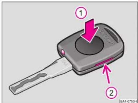
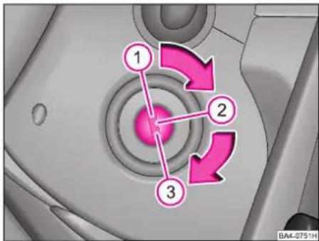
text_image
Diagram of a car key with labeled parts and directional arrows indicating movement or change.Key with light\*
The light is switched on by pressing on the middle of the key (arrow 1).
Changing battery or bulb
■Insert a coin into the slot on the side of the handle (arrow 2) and lever off top part.
■Change battery or bulb.
Replacement batteries and bulbs are available from Škoda Dealers.

Dispose of the old battery in accordance with environmental regu-ns.
CONTROLS AND EQUIPMENT
natural_image
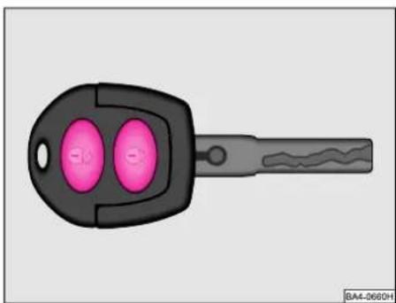
Illustration of a black key with two pink circular buttons and a gray handle (no text or symbols)Key with remote control*
For more detailed information - see page 12.
natural_image
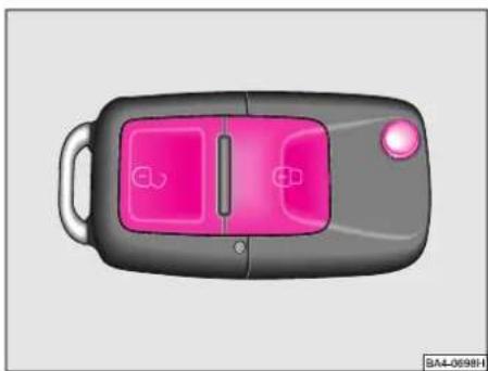
Top-down illustration of a car with pink and gray buttons (no text or symbols)The key version may differ depending on the vehicle equipment.
Refer to the text on p. 12 for further details.
Electronic immobiliser
The immobiliser prevents any unauthorized attempt to start the car.
An electronic chip with a program code is located in the head of the key. If the key with the correct code is used, the engine control unit is activated and it is thus possible to start the engine.
If the ignition key is lost or damaged, please contact your Skoda Dealer who will be able to obtain a replacement key on the basis of the code number on the key tab.
Keep the key tab separately in a safe place.
CONTROLS AND EQUIPMENT
Locking
The following procedure applies to cars not fitted with central locking:
Locking from outside
When the car is unlocked with the key, the locking button in the door moves up - refer to ill. on p. 8.
When the car is locked, the locking button moves down - refer to ill. on p. 8.
Locking from inside
All doors which are closed can be locked from the inside by pressing the locking buttons. If the locking buttons have been pressed, it is not possible to open the doors from the outside. The doors can be opened from the inside in the following way:
■Pull once on the door opening lever to unlock the door.
■Pull a further time on the door opening lever to open the door.
Note
■The opened door at the front on the driver side cannot be locked by means of the locking button. This is intended to prevent you unintentionally leaving the key in the ignition lock of the locked car.
■The opened doors at the rear and the front passenger door can be locked by pressing the locking button and closing the door.
■ Pay attention to the locking instructions - refer to p. 10.
natural_image
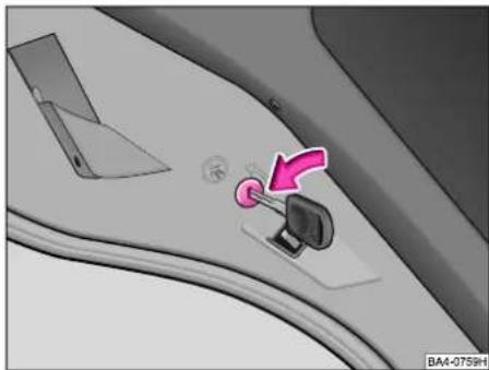
Interior view of a car showing a car's seatbelt switch and rearview panel (no text or symbols visible)Child safety lock
The rear doors are additionally fitted with a child safety lock.
■Insert car key into the slot.
■Turn the key in the direction of arrow toward the symbol. The child safety lock is activated.
The lever for opening the door on the inside is blocked. The door can only be opened from the outside.
■The child safety lock is cancelled if the key is inserted into the slot and turned in the opposite direction of the arrow. The door can then be opened in the usual way.

text_image
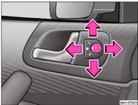
Car interior control panel with labeled buttons and a highlighted section showing a pink pill valveCentral locking system\*
The illustration shows how to operate the central locking system of a car which is equipped with the convenience system*.
All four doors and the tailgate can be locked or unlocked at the same time using the central locking system.
The central locking system can be operated as follows:
- from the outside with the car key,
- from the inside with the pushbuttons 1 and 2 in the driver's door - see illustration Button 1 - to lock car Button 2 - to unlock car
- by means of the locking buttons in the doors (refer to ill. above) only on cars which are not fitted with the convenience system (only closing).
- with the remote control.
Notes
■ When the car is unlocked, all the locking knobs move up.
- When the car is locked, the driver's door should be closed. The other doors can be closed also after the car has been locked.
■ When the car is locked, all the locking knobs should move down. If this is not the case, open the relevant door once again and close it properly.
■ The indicator light in the driver door - next to the locking button - flashes to confirm that the car has been correctly locked. The indicator light does not flash if the Safe lock has been deactivated - refer to p. 9.
This does not apply, however, to models which are equipped with the anti-theft alarm system* because the indicator lamp in this case signals that the system is active.
■The car can be unlocked and locked using button 1 and 2 in the door handle even if the ignition is switched off (provided the car is not locked from the outside).
■The tailgate can be unlocked and locked using button 1 and 2 or the car key - see chapter „Tailgate“ (Owner's Manual).
■If the central locking system fails, it is only possible to unlock and lock the front doors and the tailgate with the car key.
Opening a single door
This optional function enables you to unlock only the driver door. The other doors remain locked and are not unlocked until a further command is given (unlock). This necessitates changing the coding of the central locking control unit. This is an operation which is carried out by your Škoda dealer, who can provide you with more detailed information on this facility.
Safe lock
After the car has been locked from the outside, all the door locks are automatically blocked. It is no longer possible to pull out the inside locking knobs. The warning light in the driver's door flashes. It is not possible to open the doors either with the inside or the outside handle. This acts as a deterrent to any attempt to break into the car.
■The Safe lock can be deactivated. This is done by locking the car twice with the key or the remote control within 2 seconds.
■If the Safe lock has been deactivated, the indicator light next to the locking knob in the driver's door does not flash.
This does not apply to models which are equipped with an anti-theft alarm system* because the warning lamp signals that the system is active.
■The Safe lock is again operational once the car has been unlocked and locked again.
CONTROLS AND EQUIPMENT
Note
If the car is locked and the Safe lock is deactivated, it is possible to open the doors from the inside as follows:
■The door is unlocked by pulling the door opening handle.
■The door is opened by once again pulling the handle.
Convenience system
When unlocking and locking the car, it is also possible to open and close the power windows (only to close the sliding/tilting roof) as follows:
■Hold the key in the unlocking or locking position until all the windows are opened or closed. The opening or closing operation is stopped immediately once the key is released.
The rollback protection is not active if the convenience system is used. Refer to p. 16 for further information.
Warning
■If the vehicle is locked from the outside, make sure no persons or animals are left behind. As locked doors make outside emergency assistance difficult, never leave children or animals unattended in the car.
■Locking the doors will prevent their opening unintentionally in exceptional circumstances (accident).
Locked doors also prevent unauthorized access e.g. while waiting at traffic lights. However, they do make it more difficult for emergency workers to provide assistance inside the car.
■Check the locking process visually to ensure the locking knobs are down.
■The car is unlocked automatically if the airbag system is activated.
Storage compartments
An overview
You will find the following storage facilities in your vehicle:
■Storage compartment on the front passenger side - see page 87
■Storage compartment below the steering wheel - see page 4
■Storage compartment in the middle of the dash panel - see page 4
■Storage compartment in the door panel - see page 4
Warning
■ Please do not place anything on top of the dash panel. Such objects might slide or fall down when driving (when accelerating or cornering) and may distract you from concentrating on the traffic situation - risk of accident!
■Use the storage compartments in the door panels only for small items, which do not project out of the compartment in order to avoid any interference with the proper operation of the side airbags.
■Ensure that when driving no objects from the centre console of from other storage possibilities may get into the footwell of the driver.
You would then no longer be able to apply the brakes, operate the clutch or accelerator - risk of accident!
Tailgate
text_image
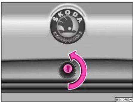
SKODA SA4-0703HTo unlock and open the tailgate:
Insert key into the lock with the slot in the vertical position, turn to the left and release. Raise tailgate handle slightly and lift tailgate open. The handle is located between the licence plate lights. The tailgate is held in the top position by a gas strut.
To lock the tailgate:
Pull the tailgate down and close with a slight swing.
Turn the key to the right and remove it from the lock.
The tailgate is maintained in the top position by a gas strut.
The tailgate is properly closed when the key slot is vertical.
Note
On models fitted with central locking system* the tailgate is automatically unlocked and locked together with the other locks.
On models fitted with anti-theft alarm system* the tailgate can only be unlocked with the remote control because the alarm is triggered after it is unlocked with key.
Warning
■Please observe the correct procedure for unlocking and opening the tailgate. If you unlock tailgate with the key and at the same time raise the handle, this can result in the opening mechanism being blocked. A blocked mechanism can be released by leaving the handle and locking the tailgate with the key. Please always follow the correct procedure to avoid damaging the opening mechanism.
■After closing the tailgate, always pull on the tailgate to check that it is properly locked - the tailgate might otherwise open suddenly when driving even if the lock has been properly closed.
■Never drive with the tailgate slightly ajar or even open otherwise the exhaust gases will be drawn into the car!
■Do not press on the rear window when closing the boot lid, it could crack - risk of injury!
If you find that the slot of the key is not vertical, an attempt has been made to break into the car. We recommend checking the vehicle equipment. Turn the slot of the key into the vertical position to ensure that the lock closes properly. As a check, lock the car once and then unlock it. If it is not possible to insert the key into the lock, the lock has been damaged. Have it repaired at a Škoda Dealer.
CONTROLS AND EQUIPMENT
Remote control\*
text_image
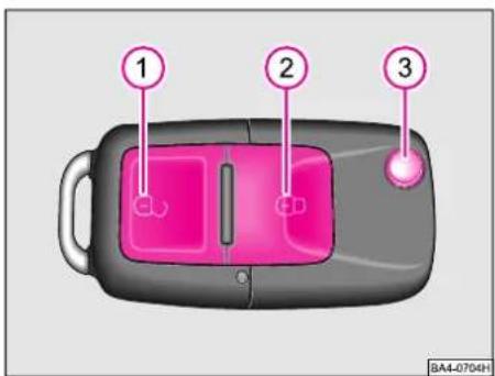
1 2 3 BA4-0704HTo unlock the car briefly press button (pos. 1).
To lock the car briefly press button (pos. 2).
To open the key - press button (pos. 3).
To close the key - press button (pos. 3) and fold the key together.
Note
The illustration shows the remote control with the folding key. The functions of Unlock, Lock, etc. are the same as for the remote control without folding key - refer to the appropriate text.
text_image
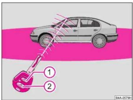
1 2 B4A-0579HThe remote control integrated in the key can be used to operate the central locking and the anti-theft warning system - see pages 8 and 13.
The central locking and anti-theft warning systems can be operated from a distance of up to 10 metres. If the batteries have lost power, the range of the remote control is reduced.
Unlocking and locking car
Tounlock the car, briefly press the button (item 2).
To lock the car, briefly press the button (item 1).
If the button (item 1) is pressed twice within 2 seconds when locking the car, the safe lock and the interior motion sensor are deactivated.
Note
After pressing one of the two buttons, the indicator light in the key flashes. If the light does not flash, the batteries in the key may be discharged. Have the batteries checked at a Škoda dealer and replaced, if necessary.
The remote control can be used to activate the anti-theft alarm system and to lock the car or to deactivate the anti-theft alarm system and to unlock the car. If the car is unlocked without the doors being opened (e.g. by pressing the button of the remote control accidentally), the car is automatically locked again after 30 seconds.
The Safe lock and the anti-theft alarm are not operational during these 30 seconds, however.
Synchronizing the car key code
If it is no longer possible to unlock the car using the remote control, the problem may be that the codes of the key and the control unit in the car no longer agree. This can happen if the buttons of the key are pressed several times beyond the effective range of the system or if the battery of the remote control has been replaced.
For this reason, the code must be re-synchronized by pressing any desired button on the remote control. Open the door with the key within one minute after pressing the button.
Anti-theft alarm system\*
General notes
The anti-theft alarm system enhances the protection provided against attempts to break into the car.
The anti-theft alarm system monitors the following parts of the car:
- Doors
- Tailgate
- Bonnet
- Ignition lock
- Interior of car 1).
- Voltage drop in electrical system.
The alarm is activated by:
■Opening the doors
■Opening the tailgate
■Opening the bonnet
■Switching on the ignition
■Movements inside the car.
The alarm is recognizable from the visual and audible signals ^2) (the flashing of the turn signal lights and the noise of the si-ren) for 30 seconds.
1) Alarm is triggered by the movement of persons in the interior of the car or by an attempt to steal the car radio. It is possible, in certain circumstances, that the rear area of the interior of the car is not fully monitored.
2) The characteristics of the visual and audible signal differ according to the country.
If a further attempt is made to break into the car after these 30 seconds, the alarm is again activated.
Operating the anti-theft alarm system
Activating alarm
Lock the car with the key or by pressing the lock button of the remote control. The monitoring functions are thus switched on.
Deactivating alarm
is deactivated by pressing the Unlock key on the remote control. The check functions are switched off in this case. If the remote control is not operating properly, you can deactivate the anti-theft alarm system in the following manner: unlock the car and then switch the ignition on.
After unlocking and not opening the doors, the alarm is reactivated after 30 seconds.
CONTROLS AND EQUIPMENT
The radio remote control can be used to activate the anti-theft alarm system and to lock the car, or to deactivate the anti-theft alarm system and to unlock the car.
Switching off interior motion sensor
The procedure for switching the interior motion sensor off and on is the same as for switching off the Safe lock - see page 9.
This function makes it possible, for example, to leave animals in the car.
Switching off alarm
If the alarm has been triggered, press and hold the Unlock button of the remote control for about one second in order to switch off the alarm. The alarm is then switched off and the car is unlocked. You can also switch off the alarm by unlocking the car with the key and the switching the ignition on. The anti-theft alarm system is re-activated by once again pressing the button (lock car).
General notes
■The life of the siren source is 5 years. Further information is available from your Škoda Dealer.
■The frequency coding of the remote control and the receiver means that it is not possible to use the remote control of other cars.
■If the key and remote control are lost, please contact your Škoda Dealer.
■The power for the remote control is supplied by batteries. If the anti-theft alarm system does not react to the remote control until you are less than 3 metres from the car or if the indicator light in the key does not flash when the button is pressed, the batteries have to be replaced. This is best done at a Škoda Dealer.
Power windows\*
text_image
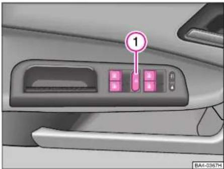
1 BA4-0367HThe switches for the individual windows are located in the armrest of the driver door, of the front passenger door and in the rear doors*.
The power windows can also be operated when the ignition is switched off.
If the ignition is switched off, the power windows can continue to be operated for about 10 minutes, but not anymore if the door is opened and closed.
The buttons in the rear doors* can be deactivated using the safety switch* 1. The windows should be closed in this case. After this, it is only possible to operate the windows in the rear doors with the switches in the armrest. After the safety switch has been pressed once again the rear switches again operate.
Opening and closing windows by means of buttons on the driver's door
Opening versions
■ The window is opened by applying slight pressure to the relevant switch in the door.
The opening operation is stopped when the switch is released.
■The front windows are automatically opened fully if the switch is pressed as far as the stop.
The window stops immediately when the switch is again pressed.
Closing
■ The window is closed by pulling up the relevant switch slightly.
The closing operation is immediately stopped when the switch is released.
■The front windows are automatically fully closed if the switch is pulled up as far as the stop.
The window stops immediately if the switch is pulled once again.
Notes
■The two switches for the rear windows each have only one closing and one opening position. The switch has to be pressed and held during the entire closing or opening operation.
■It is only possible to automatically fully open and close the two front windows using the switches in the driver's door.
■If the battery is re-connected, the top position of the closed window has to be set (system activated):
- Close all the windows with the convenience closing system.
- release the key
- After closing the window, hold the key in the closed position for a further 3 seconds or so.
CONTROLS AND EQUIPMENT
Driving in winter
In winter, the closing operation of the window may be stopped because of the higher friction resistance, caused for example by ice, and the window then returns to its initial position.
In such a case, the window must be closed in the following way:
■Pull the switch (press switch at front passenger door and at the rear doors) and hold until the window is closed.
■If closing is interrupted, repeat the operation.
Convenience operation of windows
When the car is unlocked and locked, it is possible to open and close the power windows (only to close the sliding/tilting roof), as follows:
■Hold the key in the lock in the opening or closing position until all the windows are opened or closed. The opening or closing operation is interrupted immediately when the key is released.
The rollback protection is not active if the convenience system is used. Refer to the following text for more detailed information.
Warning
■The system is equipped with a safety device to prevent injuries from bruises. If, for example, a person's arm becomes jammed in the window as it closes, the closing operation is interrupted and the window opens again a short distance. Despite this, take care when closing the windows. Persons may suffer injuries if the windows are closed inattentively or in an uncontrolled way.
■No person should be left in the car if it is locked from the outside. It is not possible to open the windows after about 10 minutes, or if the driver's door is opened and closed when the ignition is switched off.
■It is important to always pay attention when the windows are closing to avoid anyone being injured.
Rear-view mirrors
Adjusting mirrors
The rear-view mirrors should always be adjusted properly before moving off so as to ensure good vision to the rear.
Anti-dazzle inside mirror
The lever on the lower edge of the mirror should be pointing forward when the basic setting is made.
Pull lever to the rear to set the anti-dazzle position.
natural_image
Interior view of a car's head and side panel with directional arrows indicating movement or control (no text or symbols)Electrically adjustable exterior mirrors*
are set by a rotary knob in the trim panel of the driver's door. The mirror is set to the desired position by moving the rotary knob in the desired direction with the ignition switched on.
Position
Heating exterior mirror (applies only to models with power windows)
Position L
- left-hand and right-hand mirrors at the same time (applies to models with convenience system)
- left-hand mirror (applies to models without convenience system)
Position R
Adjusting the right-hand mirror
If the electrical adjustment of the mirrors fails, the mirrors can be adjusted by hand by pressing on the edge of the surface of the mirror.
Exterior mirror heating
(applies only to models not fitted with power windows)
When the ignition is switched on, the exterior mirrors are heated provided the rear window heater is also operating.
Note for using convex or aspherical exterior mirrors:
Convex exterior mirrors (curved outwards) enlarge the field of view but they make objects look smaller.
These mirrors are only of limited use in estimating how far away a following vehicle is.
Aspherical exterior mirrors have a mirror surface with different curvature. This wide-angle mirror increases the field of view even more so than conventional convex mirrors.
These mirrors are also only of limited use in estimating how far away a following vehicle is.
Warning
Use whenever possible the interior rear mirror, for estimating the distance to the following vehicles.
CONTROLS AND EQUIPMENT
Head restraints
text_image
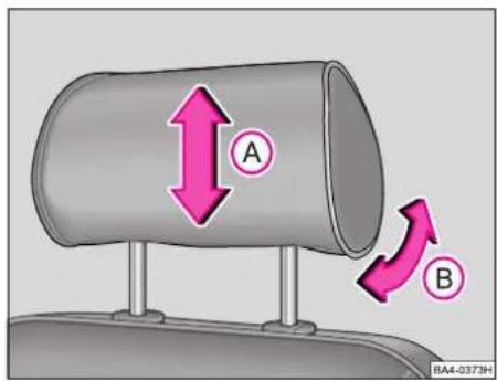
A B RA4-0373HThe head restraints can be adjusted for angle and height and should be set to match the size of the seat occupant. Head restraints which are correctly adjusted offer effective protection together with the seat belts.
Adjusting height
■Grasp the side of the head restraint with both your hands and pull it up or down in direction of arrow A.
■The best protection is obtained if the upper edge of the head restraint is roughly at eye level or higher.
Warning
In case the head restraints are not correctly adjusted or when driving without head restraints, you are exposed to a risk of injury.
Adjusting angle
■The head restraints can be tilted in the direction of arrow B and can be matched to head height in the desired position to provide enhanced comfort for the occupant.
natural_image
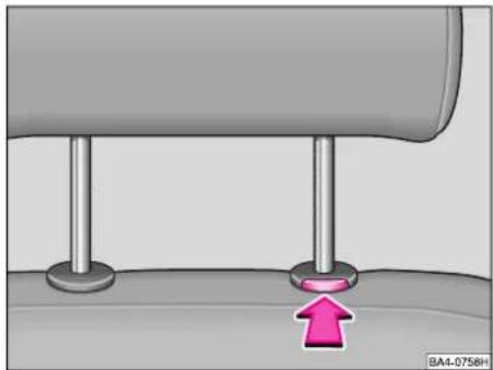
Mechanical assembly diagram showing a piston and base with a pink arrow indicating motion (no text or symbols)Removing and installing
Pull the head restraint out of the backrest as far as the stop. Press the locking button in direction of arrow and pull the head restraint out of the backrest.
To install again, push the head restraint rods into the guides until the locking button is heard to engage.
Front seats
Correct seat adjustment is important for:
- reliably and quickly reaching the controls and switches,
- relaxed, fatigue-free body position,
- maximum protection from the seat belts.
Warning
■For this reason, the front seats should not be pushed too close to the steering wheel or the instrument panel.
■Each occupant must correctly fasten the seat belt belonging to the seat. Children must be fastened with a suitable restraint system - see page 111.
■The front seats and the head restraints must always be adjusted to match the body size of the seat occupant. The seat belts must always be correctly fastened in order to provide an optimal protection for you and your occupants.
■Always keep your feet in the foot-well when the vehicle is moving - never rest them on the instrument panel or seats.
■Never transport more occupants than the maximum seating in the vehicle.
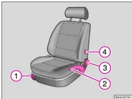
text_image
1 2 3 4 BA4-0374H1 - To move seat forward and back
Pull up the lever located below the seat and move seat into the desired position. Then, release lever and move seat further until the lock engages.
The driver's seat should be adjusted so that the pedals can be fully depressed with the legs slightly angled.
Warning
For safety reasons the driver's seat must only be moved forward or back when the vehicle is stationary!
2 - Adjusting seat height\*
Move the lever repeatedly up and down in the top position in order to raise the seat. Move the lever repeatedly up and down in the bottom position in order to lower the seat.
Warning
For safety reasons the height of the driver's seat must only be adjusted when the vehicle is stationary!
CONTROLS AND EQUIPMENT
3 - Adjusting backrest angle
To adjust the backrest, take weight off back-rest and then turn knob.
The backrest of the driver's seat should be adjusted so that the top of the steering wheel can be reached with the arms slightly angled.
Warning
Do not lower the backrest too far when travelling otherwise the protection offered by the seat belts will be adversely affected.
4 - Adjusting lumbar support\*
The seat padding in the lumbar area of the spine can be made to arch forward slightly by turning the handwheel. This offers effective support to the natural curvature of the spine. The sitting position is less fatiguing, particularly on long trips.
Electrically operated seat\*
text_image
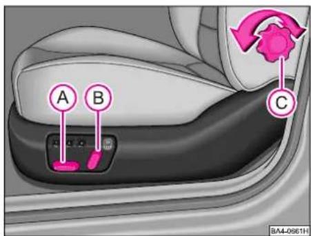
A B C BAI-0661HElectric seat adjustment
The seat is positioned electrically with switches A and B.
The seat can also be positioned when the ignition is switched on.
The backrest of the seat is positioned mechanically by turning the wheel C.
Warning
■For safety reasons the seat must only be adjusted when the vehicle is stationary!
■Take care when adjusting the seat! Risk of injury if the seat is moved without proper attention or in an uncontrolled manner.
■The electric adjustment of the seat also operates when the ignition is switched off or the ignition key withdrawn. For this reason, never leave children unattended in the vehicle.
text_image
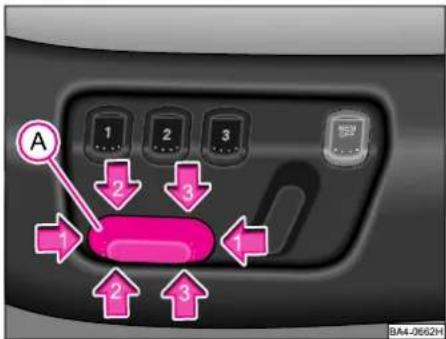
A 1 2 3 2 3 1 2 3 BA4-2662HSwitch A
The seat is moved in the particular direction of the arrow by pressing the switch:
1 - Seat forward / back
2 - Front seat surface raised / lowered
3 - Rear seat surface raised / lowered
2 and 3 together - Seat height adjusted.
text_image
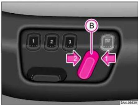
1 2 3 B 2 1 BA4-0663HSwitch B
The backrest is set in the particular direction of the arrow by pressing the switch:
Direction of arrow 1: backrest angle steeper.
Direction of arrow 2: backrest angle flatter.
Warning
The backrest of the seat must not be tilted too far back when driving otherwise proper operation of the seat belts will be affected.
CONTROLS AND EQUIPMENT

text_image
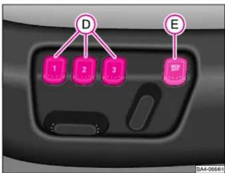
D E 1 2 3 SP 3A4-0664HMemory for driver's seat
The memory of your driver's seat offers the possibility of storing your own individual settings for the seat and exterior mirrors. It is possible to store the individual settings for up to three drivers in each case using the memory button D. If another person drives the car, it is then only necessary to press button D for the seat and exterior mirrors to be set automatically to the individually programmed position.
Memory button D can be used to store and retrieve the
- individual settings of the driver's seat,
- Storing and retrieving exterior mirror settings (on left and right) for driving forward, or exterior mirror setting (on right) for reversing.
In addition, you can use the keys of the remote control* to retrieve the stored settings of a memory button.
The memory system can be switched off at any time with the lock switch E. The seat and the exterior mirrors can then only be adjusted manually.
Storing seat and mirror settings for driving forward
■Switch the ignition on.
■Adjust the seat - see pages 20 and 21.
■Adjust both exterior mirrors - see page 16.
■ Press one of the memory buttons D and hold the button for about three seconds until an audible signal confirms that the settings have been stored.
The settings are then stored under the memory button selected.
Storing exterior mirror setting for reversing\*
■Switch the ignition on.
■Switch over operation of the exterior mirror to position R.
■Shift into reverse gear.
■Position the exterior mirror on the right into the desired setting - refer to p. 17.
■ Press one of the memory buttons D and hold the button for about three seconds until an audible signal confirms that the setting has been stored.
The settings are stored under the selected memory button.
Notes
■We recommend beginning with the left-hand button for the memory assignment and allocating a memory button to each additional driver.
■Each new setting which is stored with the same button cancels the previous setting.
■Each time new settings are stored for the seat and mirrors for driving forward, it is also necessary to re-store the individual setting of the right-hand exterior mirror for reversing.
Assigning remote control keys\* to the memory buttons
If you wish to be able to retrieve the settings stored in the memory using the remote control key, you must assign the keys to a particular memory button.
We recommend assigning one of the two factory-supplied remote control keys to the left-hand memory button and the other keys to the middle button.
You can obtain an additional remote control key, if necessary, from your Škoda Dealer and then assign it to the right-hand memory button.
Carry out the following procedure to assign the remote control keys:
After storing the settings of the driver's seat and mirrors, you have 10 seconds to assign the remote control key to the corresponding memory.
■Withdraw the remote control key from the ignition lock for this purpose.
■Press the opening button of the remote control key - see page 12 and hold the button for about one second until an audible signal confirms the assignment has been made.
The setting is stored under the memory button you selected.
Notes
■If the remote control key has already been assigned to another memory button, the „old“ assignment is cancelled.
■If the remote control key is assigned to a memory button which has already been assigned to another key, the „old“ assignment is also cancelled in this case.
■The assignment of a remote control key to a memory button is retained even if you store new seat and mirror settings with this button.
text_image
D E 1 2 3 BA4-06641Retrieving seat and mirror settings for driving forward
You can retrieve the stored settings by using the memory buttons D as well as the remote control*.
Retrieving with the memory buttons
For safety reasons, you are able to retrieve the seat and memory settings only if the ignition is switched off. You have two possibilities for retrieving the settings in this case:
„One-touch automatic memory“: With the driver door opened, briefly press on the desired memory button D. The seat and exterior mirrors now move automatically into the stored position.
CONTROLS AND EQUIPMENT
„Multi-touch memory retrieval“: With the driver door opened or closed, continuously press the desired memory button D until the seat and exterior mirrors have moved into the stored position.
Note
If one of the memory buttons is once again pressed during the automatic adjustment of the seat and exterior mirrors, the retrieval process is interrupted. In this case, again press the key which you pressed first in order to continue the interrupted retrieval process. If, on the other hand, you press one of the other two buttons, the seat and mirrors will then move to the positions stored with these buttons.
Retrieving with the remote control\*
You can only retrieve the stored seat and mirror settings if the ignition is switched off and the driver door is closed:
Briefly press the opening button of the remote control key - see page 9, and then open the driver door.
The seat and the exterior mirrors now move automatically into the stored positions.
Retrieving exterior mirror setting for reversing\*
When reverse gear is engaged, switch over operation of the exterior mirror settings to position R - refer to p. 17.

text_image
D 1 2 3 E 3A4-0664HNotes on use of the lock switch E
■ After the lock switch E is pressed (released), the memory system is permanently switched off. You can now set the seat and the exterior mirrors only manually. You can switch on the memory system again by once again pressing the lock switch E. If a retrieval process was interrupted when this switch was first pressed, the process is not continued.
■We recommend switching off the memory system with the lock switch E if the car is to be driven for a short time by a person for whom you do not wish to store the individual seat and mirror settings.
Emergency off
In an emergency, the memory retrieval process can be interrupted by pressing (releasing) the lock switch E, briefly pressing one of the memory buttons or pressing one of the seat setting switches.
Rear seat
The rear seat can be folded forward in order to increase the available luggage space.
Before folding the seat backrest down, it is necessary to adjust the front seats and the armrests so that after folding down the armrests and the backrests of the front and rear seat are not deformed or damaged.
natural_image
Interior view of a car showing a seatbelt buckle and neck (no text or symbols visible)Folding rear seat forward
■Pull up seat cushion with the aid of the loop and fold forward.
■Pull release knob up and fold backrest of rear seat forward slightly.
■Remove head restraints from backrest of rear seat and fold the backrest fully forward.
■The head restraints can be inserted into the openings of the backrest when it is folded forward.
CONTROLS AND EQUIPMENT
Folding rear seat back
■First of all, insert head restraints into the backrest.
■Then, fold back rear seat backrest until it locks in position - pull as a check. Fold back seat into its original position.
Note
After folding back the seat cushion and the rear seat backrests, the seat belt buckles and the lap belt should be in their original position - they should be ready for use.
Warning
The backrests of the rear seat should be properly locked to ensure that no objects can slip forward out of the luggage compartment into the interior of the car during a sudden application of the brakes.
Luggage compartment cover
Warning
No objects should be carried on the luggage compartment cover. These may result in injuries to occupants in the event of a sudden application of the brakes or an accident.
In addition, the heater elements of the rear window may be damaged by objects rubbing against them.
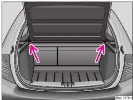
natural_image
Top-down view of a car trunk with two pink arrows pointing to the rear opening (no text or symbols)The luggage compartment cover is automatically raised when opening the tailgate. The cover can be removed in order to transport bulky items:
■Unhook retaining cords from the tailgate.
■Pull the cover back out of the side retainers (see arrows).
The cover can then be stowed behind the rear seat backrests.
■When installing, slide the cover forward into the side retainers and hook the retaining cords onto tailgate.
Luggage compartment
To ensure proper handling of your car, always distribute any load which you carry (passengers and luggage).
Heavy objects should be transported as close as possible to the rear suspension, or even better between the front and rear.
In addition, please ensure that the heater elements of the rear window are not damaged by objects rubbing against them.
In the event of an accident, there is such a high kinetic energy, which is produced by small and light objects that they can cause severe injuries.
The magnitude of the kinetic energy depends on the speed at which the vehicle is travelling and on the weight of the object. The speed at which the vehicle is travelling is in this case the more significant factor.
Example: In the event of a frontal collision at a speed of 50 km/h, an unsecured object with a weight of 4.5 kg produces an energy, which corresponds to 20 times its own weight.
This means that it results in a weight of approx. 90 kg.
You can imagine the injuries that can occur, if this „bullet“ is flying through the interior compartment and hits an occupant.
Warning
■Store the objects in the luggage compartment and attach them to the lashing eyes.
■ Loose objects in the passenger compartment can be thrown forward during a sudden manoeuvre or in case of an accident and they can injure the occupants or other oncoming traffic. This risk is still increased, if the objects, which are flying around, are hit by a deployed airbag.
In this case, the objects, which are thrown back, can injure the occupants - hazard!
■Never drive with the tailgate ajar or even open otherwise exhaust gases will be drawn into the interior! ■Please note that when you transport heavy items, this results in a change in the centre of gravity of the vehicle and thus affects the handling. You should therefore adjust your style of driving and speed to match, and also alter the setting of the headlights, if necessary.
CONTROLS AND EQUIPMENT
■On no account exceed the permissible axle loads and the permissible gross weight of the vehicle - risk of accident! ■Never transport occupants in the luggage compartment.
The air circulation in the interior of the car helps to prevent the windows from misting up.
Stale air is diverted via the outlet nozzles into the lateral trim panels of the luggage compartment.
Check for yourself that the outlet nozzles are not covered.
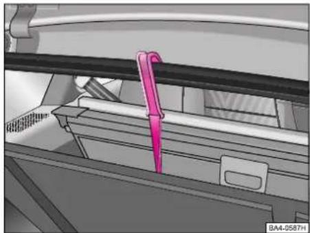
natural_image
Mechanical assembly diagram showing a pink tool inserted into a component (no text or symbols visible)Attachment of floor covering of luggage compartment (Estate)
■A hook is attached to the loop of the floor covering of the luggage compartment.
■It is possible, if necessary, to attach the raised floor covering with the hook to the opening in the tailgate - see arrow - for example to gain access to the spare wheel.
Lashing rings
Lashing rings (see arrows) are fitted on both sides of the luggage compartment to secure items of luggage.
Warning
Any items carried in the luggage compartment should be properly attached so that they cannot move when driving and braking.
If the items of luggage or objects are attached to the lashing eyes with unsuitable or damaged lashing straps, injuries can occur in the event of braking manoeuvres or accidents.
In order to prevent the items of luggage being thrown forward, always use suitable lashing straps which are firmly attached to the lashing eyes. Never attach a child seat to the lashing eyes.
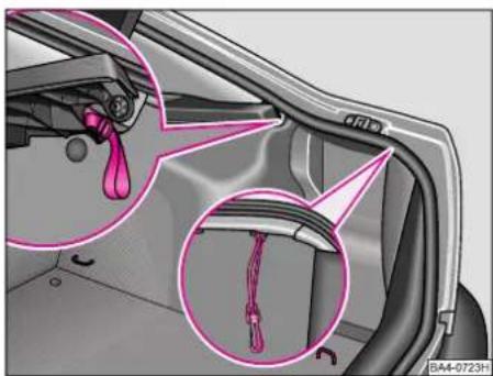
natural_image
Interior view of a car showing a handle, cable, and connector (no text or symbols visible)Securing rings in Octavia
The securing rings are located in the load area of the boot, or you can use hooks which you fit into the openings in the body - see illustration.

natural_image
Interior view of a car backrest with pink arrows pointing to structural components (no text or symbols)Securing eyes in Octavia Estate
The securing rings are located in the load area of the boot, or you can use the hooks of the luggage compartment nets - see illustration.
CONTROLS AND EQUIPMENT
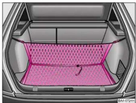
natural_image
Interior view of a car showing the backrest area with a pink patterned blanket (no text or symbols visible)Luggage compartment net\*
It is also possible to attach a security net to the rings in the boot for lashing down small items.
Example for attaching vertical double net (bag) in Octavia - see illustration.
natural_image
Interior view of a car showing the backrest area with pink mesh pattern and a small handle (no text or symbols visible)Example for attaching vertical double net in Octavia - see illustration.
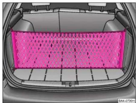
natural_image
Interior view of a car showing the backrest grille with a pink mesh fence (no text or symbols visible)Example for attaching partition net in Octavia Estate - see illustration.

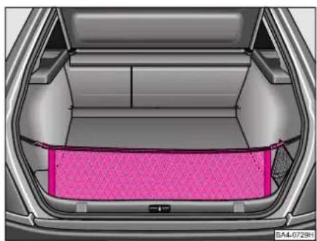
natural_image
Interior view of a car showing a pink mesh-patterned storage tray (no text or symbols visible)Example for attaching load area net in Octavia Estate - see illustration.

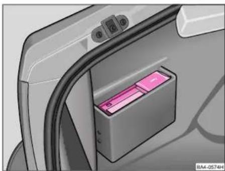
natural_image
Interior view of a car showing the backrest and side panel with a pink mesh cushion (no text or symbols visible)Example for attaching side net in Octavia Estate - see illustration.
natural_image
Close-up of a charging cable connector with a pink internal component, no visible text or symbolsCD changer\*
The CD changer for the car radio is located in the left of the luggage compartment.
The description for changing the CDs is included in the instructions of the CD changer.
CONTROLS AND EQUIPMENT
Luggage compartment cover (Estate)
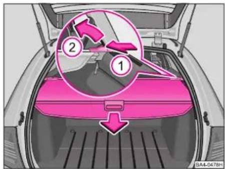
text_image
Diagram of a car trunk with labeled parts, showing numbered instructions for assembly or repair.■Pull the luggage compartment cover in the direction of the arrow into the recesses on the sides of the luggage compartment.
■The cover can be removed for transporting bulky items. Press on the side of the transverse bars in direction of arrow 1. Take out the cover in the direction of arrow 2.
Warning
No objects should be carried on the luggage compartment cover. The occupants of the car are at risk in the event of a sudden application of the brakes or an accident.
In addition, the heating elements of the rear window could be damaged by objects rubbing against them.
Raised luggage area\* (Estate)

text_image
A A RA4-0517HThe raised luggage area makes it easier to put in and remove large items. This can be removed by adopting the following procedure:
■Release the luggage area by turning the locking pins A about 90° to the left.
■Raise the luggage area in direction of arrow and take out.
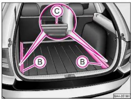
text_image
C B B BA4-0518H■ Release the supporting bars B by turning the plug-in rings C about 90° to the right and take out.
The luggage area is installed in the reverse order:
■ Insert the supporting bars B into the original position. Attach in the rings of the body by turning the plug-in rings C about 90° to the left.
■Place the still folded luggage area onto the supporting bars B. Then pull luggage area apart.
■Secure luggage area by turning the locking pins A about 90° to the right.
Warning
When installing luggage area, ensure that the supporting bars and the raised luggage area are correctly attached. Otherwise, the occupants of the car may be at risk of injury.
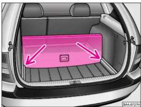
natural_image
Interior view of a car showing a pink cargo tray with two arrows pointing to it, no text or symbols present.Lining luggage compartment with increased load area
The luggage compartment can be lined with an increased load area.
■Raise part of the load area with hooks and secure it by inserting into the slots -arrows-.
Net partition Estate\*

text_image
A C B BA4-0718HThe net partition can be used either behind the rear seats or behind the front seats. Remove the luggage compartment cover before installing the net partition - refer to page 32 of the Owner's Manual.
Use of net partition behind rear seats
Unrolling
Grasp the net partition at plate A and pull it out of housing B at an angle of about 45° in the direction of the tailgate. Place the one end of the top cross rod into the mount C in the roof member. Now push the cross rod forward slightly and fit the other end of the rod into mount C of the other roof member.
CONTROLS AND EQUIPMENT

text_image
C B BA4-071991Rolling up
Pull the top cross rod back slightly, first on the one side, then on the other side, and take the rod out of the appropriate mount C.
Guide the net partition down by hand at an angle of about 45^ in the direction of the tailgate as it moves into housing B. Do not allow it to snap down!
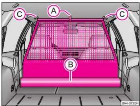
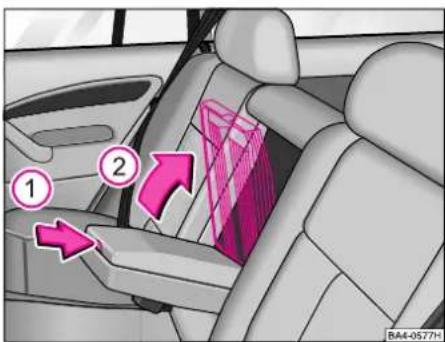
text_image
A B C C BA4-0720HUse behind the front seats
Remove the head restraints and fold the front seats forward. Grasp the plate A and pull the net partition out of housing B. Insert the one end of the top cross rod into the front mount C. Now, press the cross rod forward slightly and fit the other side of the rod into the mount C on the other side.
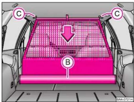
text_image
C B C BA4-0721HRolling up
Pull the top cross rod back slightly, first on the one side, then on the other side, and remove the rod from the appropriate mount C.
Guide the net partition by hand as it moves down into the housing B. Do not allow to snap down!
CONTROLS AND EQUIPMENT
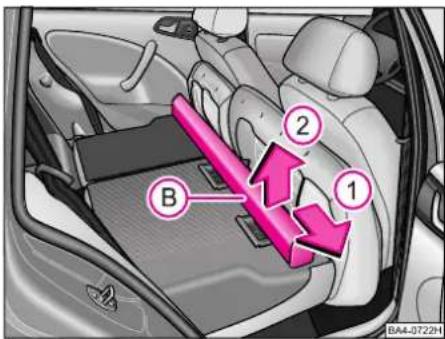
text_image
B 1 2 BA4-0722HRemoving complete net partition
Remove the head restraints and fold the rear seats forward.
Open the rear right door.
Then, push housing B in the direction of arrow 1 as far as the stop and take it out of the mounts of the rear seat backrests in the direction of arrow 2.
Installing complete net partition
Position housing into the mounts of the rear seat backrest.
Then, push the housing in the opposite direction of arrow 1 as far as the stop.
Fold rear seats back.
Pedals
Proper operation of the pedals must not be obstructed by any objects!
For this reason, do not put articles in the footwell which could roll or slide underneath the pedals.
There should not be any foot mats or other additional floor coverings around the pedal area.
■Greater pedal travel may be necessary if there is a fault in the brake system.
■It should always be possible to depress the clutch and accelerator pedals fully.
■All the pedals must be able to return, unhindered, to their rest positions.
For these reasons, only fit foot mats which leave the pedal area completely free and which have a non-slip surface.
CONTROLS AND EQUIPMENT
Handbrake

natural_image
Car seatbelt mechanism diagram showing a pink belt being inserted into the seat (no text or symbols present)Pull the lever up firmly in order to apply the handbrake. In addition, on a steep hill, also engage 1st gear (or position P on cars with an automatic gearbox). The handbrake lever should therefore always be applied firmly to avoid driving off inadvertently without releasing the handbrake. The handbrake warning light comes on when the handbrake is applied and the ignition is switched on, see also page 61.
To release handbrake, pull lever up slightly, press locking knob in and push lever fully down.
Armrest\*

text_image
A B I4A-0538HFront armrest
To fold down the armrest, press the button A on the front end of the armrest. Fold down armrest and release button again.
The movement of your arm may be restricted if the armrest is folded down. It is therefore recommended not to drive in towns with the armrest folded down.
A stowage compartment is provided in the armrest. Press button B to open the stowage compartment and raise lid.
natural_image
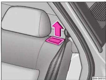
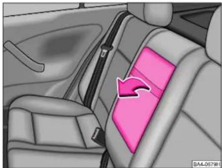
Interior view of a car showing the backrest seat with pink cushion and seatbelt (no text or symbols visible)Rear armrest\*
The armrest at the rear can be folded down by pulling on the strap in the direction of the arrow.
CONTROLS AND EQUIPMENT
Mobile phone, hands-free system\*
text_image
Diagram of car interior with numbered arrows indicating directional movement or flow, labeled 1 and 2.A stowage compartment is provided in the armrest. To open the stowage compartment, press button in direction 1 and raise lid in direction 2.
text_image
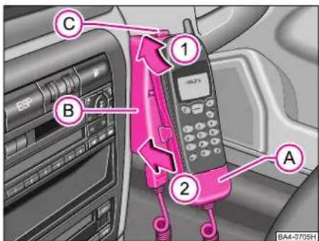
C B 1 A 2 BA4-0705HThe mounting for a portable cellphone is supplied with the car. The mounting is attached in the middle of the dash panel.
Adapter (Cullmann) and mobile phone are not supplied with the car.
■Insert cellphone (as specified in manufacturer's instructions) into adapter A.
■Plug the adapter cable into the socket for the cellphone. The socket is located in the bottom of the mounting. Your Škoda dealer can provide you with more detailed information.
Press the button C, in order to take the telephone with the adapter out of the fixture.
Refer to the information on p. 159.
Placing adapter and cellphone into the holder
■Place the adapter and cellphone into the holder B, first of all in direction of arrow 1 until the adapter is resting against the stop. Push the adapter slightly in direction of arrow 2 until it locks in place.
This enables you to make use of the advantages of the commercially available cellphone („hands-free system“) with the microphone integrated in the car, which offers a higher quality of interference-free transmission with an external aerial. At the same time, the cellphone battery remains constantly charged.
CONTROLS AND EQUIPMENT
In order to ensure an error-free function of your cellphone during cellphone operation, the following measures for the adapter initialisation must be carried out before connecting the adapter cable:
■Pull the ignition key out of the ignition lock.
■Place the adapter into the holder (no cellphone must be placed into the adapter).
■Plug the cable into the socket for the cellphone.
■Switch on the ignition
■Wait 20 seconds then switch off the ignition and pull the ignition key out of the ignition lock.
■Place the cellphone into the adapter (refer to manufacturer's instructions) and switch on the ignition.
The initialisation has to be carried out, if:
- the adapter is connected for the first time,
- the battery is disconnected and connected again,
- the adapter cable was pulled out of the cellphone socket.
Manual gearbox

text_image
① ③ ⑤ R ② ④ BA4-0643HShift pattern 5-speed manual gear-box
Reverse gear must not be engaged unless the car is stationary. When the engine is running, depress the clutch pedal fully and wait a few seconds before engaging a gear in order to achieve a smooth gearshift.
When reverse gear is engaged with ignition on, the reversing lights come on.
text_image
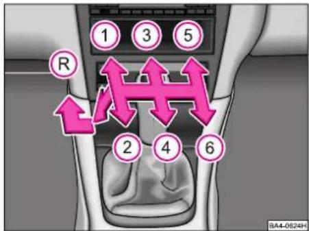
① ③ ⑤ R ② ④ ⑥ BA4-0624HShift pattern 6-speed manual gear-box
Note
Depress the clutch pedal fully when changing gears, in order to avoid unnecessary wear and damage.
When driving, you should not rest your hand on the gear lever. The pressure of your hand is transmitted to the selector forks in the gearbox and can cause premature wear on the forks.
Automatic gearbox\*
natural_image
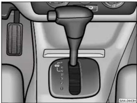
Interior view of a car showing a hand crank and gear shift lever (no text or symbols visible)Selector lever positions
The selector lever position engaged (refer to illustration) is indicated in the display panel*.
P - Park lock
The driven wheels are mechanically blocked.
Warning
The Park lock must not be engaged unless the vehicle is stationary otherwise the Park lock might be damaged.
Before moving the selector lever into or out of position „P“, the lock button in the selector lever handle has to be pressed. In addition, the brake pedal has to be depressed first of all before moving out of this position with the ignition switched on.
text_image
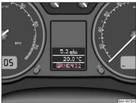
EPC 5.3 20.0 °C RND432 BA4-0672HR - Reverse gear
Reverse gear must only be engaged if the vehicle is stationary and the engine is idling. Before moving selector lever into position „R“ from positions „P“ or „N“, the brake pedal has to be depressed and the lock button in the selector lever handle pressed in. When the selector lever is moved into position „R“ and the ignition is on, the reversing lights come on.
N - Neutral
To move the selector lever out of „N“ at a speed of less than 5 km/h (3 mph) and also when vehicle is stationary and the ignition on, depress brake pedal and press in lock button in selector lever handle (if the selector lever remains in this position for more than 2 seconds).
D - Continuous position for driving forward
In this position, the four forward gears are shifted up and down automatically in line with engine load, the speed of the car and your style of driving.
To shift out of position „D“ into „3“, the lock button in the selector lever handle must first of all be pressed in.
3 - Position for hilly sections
This selector lever position is recommended if holding the position „D“ would result in frequent gear changes in certain driving conditions.
1st, 2nd and 3rd gears are automatically shifted up and down in line with engine load, the speed of the car and your style of driving. 4th gear cannot be engaged. This ensures increased engine braking power when the accelerator is released.
The shiftlock button must not be pressed in the grip of the selector lever in order to shift from position „3“ into „2“.
CONTROLS AND EQUIPMENT
2 - Position for mountainous sections
This selector lever position is suitable for long mountainous stretches.
1st and 2nd gears are automatically shifted up and down in line with engine load, the speed of the car and your style of driving. 3rd and 4th gears cannot be engaged in order to avoid the gearbox shifting up unnecessarily. This increases the engine braking power.
To shift out of position „2“ into „1“, the lock button in the selector lever handle has to be pressed in.
1 - Position for steep mountainous stretches
This selector lever position is recommended for extreme downhill stretches.
The car runs only in 1st gear. 2nd, 3rd and 4th cannot be engaged. This ensures that the maximum possible engine braking power is available.
Note
When shifting down manually, it is possible to engage selector lever positions „3“, „2“ and „1“, although the automatic gearbox does not shift down until there is no longer any risk of the engine overrevving.
Selector lever lock
The selector lever is locked in the positions „P“ and „N“ when the ignition is switched on. The warning light on the cover panel next to the selector lever comes on and remains on until the brake pedal is depressed. The brake pedal has first of all to be depressed and at the same time the lock button in the selector lever handle pressed in to shift the selector lever out of these positions. This is intended to ensure that it is not possible to inadvertently engage a gear and for the car to move off unexpectedly.
A time delay element ensures that the selector lever is not blocked if it is shifted rapidly through position „N“ (e.g. from „R“ to „D“). This makes it possible, for example, to „rock“ the car free if it is stuck in mud or snow. The selector lever lock does not engage unless the lever is held for more than 2 seconds in position „N“ without the brake pedal being depressed.
The selector lever lock is switched off automatically in the position „N“ and speeds of more than 5 km/h.
Information for driving
Starting engine
The engine can only be started if the selector lever is in position „N“ or „P“ - see page 44.
Selecting a forward gear
Always first of all depress the brake pedal before selecting a forward gear when the vehicle is stationary and the engine is running.
Do not depress the accelerator when moving the selector lever if the car is stationary.
If you inadvertently move the gearshift lever into position „N“ when driving, you first of all have to release the accelerator and wait until the engine is running at idle speed before again engaging a forward gear.
Warning
When the engine is idling and the car is stationary (e.g. at traffic lights or when stopped in congested traffic) it is always necessary to depress the brake pedal in order to hold the vehicle no matter the selector lever position, because the power transmission is not fully interrupted even when the engine is idling and the car may creep forward.
If a forward gear is engaged when the vehicle is stationary, on no account inadvertently operate the throttle (e.g. by hand from the engine compartment) otherwise the car will immediately move forward - this may also happen even if the handbrake is properly applied.
Move selector lever into position „P“ and apply the handbrake before carrying out any work on the running engine.
Driving off
Select a gear (R, D, 3, 2, 1). Wait until the gearbox has shifted into gear and the power is transmitted to the driven wheels (can be felt from a slight engagement jolt) before then pressing the accelerator.
Coming to a stop
You do not have to move the selector lever to position „N“ if stopped only for a short time, e.g. at traffic lights. It is sufficient to hold the car with the brake. The engine must only be running at idling speed, however.
Parking
On the flat it is sufficient to engage the Park lock. If parked on a downhill stretch, first of all apply the handbrake fully and then engage the Park lock. Doing this ensures that there is no excessive stress acting on the Park lock mechanism and the Park lock can be more easily released.
Warning
When the car is parked, the selector lever should always be moved into position „P“ for only this position prevents the car moving off by itself.
CONTROLS AND EQUIPMENT
Tow-starting
If your car is fitted with an automatic gearbox, it is not possible to start the engine by tow-starting or pushing the car - see page 178.
If the battery is discharged, jump-starting cables can be used for connecting the battery of another car to start the engine - see page 177.
Towing car
It is essential to refer to the information on page 179 if it is necessary to tow in the car.
Drive programs
The automatic gearbox features various drive programs. Depending on your style of driving or the driving situation, an economy, in other words consumption-oriented program, or a sport program is selected.
The program is selected automatically depending on how the accelerator pedal is operated.
If the accelerator pedal is depressed slowly, the gearbox selects the economy program. This offers improved fuel economy.
If the accelerator pedal is depressed rapidly, the gearbox selects the sport program.
Kickdown
The kickdown facility makes it possible to achieve maximum acceleration. If the accelerator pedal is depressed as far as the stop, the automatic gearbox shifts down into a lower gear in line with the speed of the car and of the engine. The gearbox waits until engine speed has reached the maximum specified speed in each case before shifting up into the next higher gear.
Emergency program
If a fault develops in the gearbox electronics, emergency programs are activated depending on the type of fault.
■The gearbox does continue to shift automatically but more severe shift jolts can be felt in this case. You should drive the car to the nearest Škoda Dealer.
■The gearbox no longer shifts automatically.
In this case, the gearbox can still be shifted manually but only 3rd gear is available in the selector lever positions „D“, „3“ and „2“.
1st gear and Reverse gear are available as usual when the selector lever is moved into positions „1“ and „R“.
However, the torque converter has to perform more work, particularly because 2nd gear is no longer available. In such cases, it is possible that the gear oil may become too warm.
It is therefore necessary to drive the car immediately to a Škoda Dealer.
Adjustable steering column
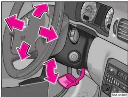
natural_image
Interior view of a car showing dashboard, steering wheel, and seatbelt with pink directional arrows indicating rotation (no text or symbols)The steering column can be adjusted for angle and length.
■First of all, properly adjust the driver's seat.
■Swivel lever below steering column down as far as the stop.
■ Adjust the angle and length of the steering wheel to suit your body proportions.
■Push the lever back up again - toward the steering column.
Warning
The steering column must not be adjusted when driving.
For safety reasons, the lever must always be pressed firmly up again so that the steering wheel cannot move while the vehicle is in motion.
Ignition lock
text_image
1 2 3 BA4-0751HPetrol engines
1 - Ignition off, engine off
2 - Ignition on
3 - Starting engine
Diesel engines
1 - Fuel supply cut off, engine off
2 - Preglow (ignition off)
Do not switch on any large current consumers when heating the glow plugs to prevent draining the battery unnecessarily.
3 - Starting engine
CONTROLS AND EQUIPMENT
For all models:
Position 1
To lock the steering wheel, withdraw key and turn wheel until you hear the locking pin engage.
Warning
Do not withdraw key from lock until vehicle is stationary! The steering lock might otherwise unintentionally engaged.
Note
If you forget to switch off the side lights or a turn signal light, an audible signal will sound after you switch off the ignition or withdraw the key and then open the driver's door.
Position 2
If the key is difficult to turn in the lock or cannot be turned to this position at all, move the steering wheel back and forward slightly to release the locking pin.
Warning
If the vehicle is allowed to roll, the ignition key must be in position 2 in the lock - ignition on. This position is also indicated by the warning lights coming on. Failure to turn the ignition key into this position can result in the steering locking unintentionally.
Do not withdraw the ignition key until after the vehicle has come to a stop and has been properly secured to prevent it moving by applying the handbrake or engaging a gear.
Position 3
The starter is operated when the key is turned into this position. The ignition key must be turned back each time into position „1“ before again attempting to start the engine. The starter repeat lockout in the ignition lock prevents the starter again being operated when engine is already running.
When the key is in this position, the main/low beam headlights and other major electrical components which are on, are then switched off.
The starter may only be operated (ignition key position 3), if the engine is not running. If the starter is immediately operated after switching off the engine, the starter or the engine can be damaged.
Starting engine
General notes
Warning
Never run the engine in non-ventilated or enclosed areas, the exhaust gases of the engine contain besides the odourless and colourless carbon monoxide a poisonous gas - hazard! Carbon monoxide can cause unconsciousness and death.
Never leave your vehicle unattended with the engine running.
■Before starting, move gear lever into Neutral (selector lever of automatic gearbox into position „P“ or „N“) and apply handbrake firmly.
■On models with a manual gearbox, depress the clutch pedal when operating starter so that the starter only has to crank the engine.
■As soon as engine starts, release ignition key immediately - otherwise the starter may suffer damage.
■After starting a cold engine, it may sound noisy for a moment or two because the oil pressure has to build up in the hydraulic tappets first.
Do not warm engine up by running it with vehicle stationary. Drive off straight away.
■Avoid high revs and running the engine at full load until the engine has reached its normal operating temperature.
■Do not allow the engine to idle for a lengthy period. If the engine is running when the car is stationary, there is not always an adequate flow of air through the radiator. In certain circumstances, this can result in the engine overheating and also in engine damage.
■On vehicles with a catalytic converter the engine must not be started by towing the vehicle more than 50 m. Otherwise, unburnt fuel can pass into the catalytic converter and cause damage.
■Before trying to start engine by towing, use the battery from another vehicle for jump-starting if possible - see page 177.
Petrol engines
These engines are equipped with a petrol injection system that automatically supplies the correct fuel/air mixture at all ambient temperatures.
The information for starting these engines therefore applies irrespective of the outside temperature and is the same whether the engine is cold or at normal operating temperature:
■Do not operate throttle before and when starting the engine.
■If the engine does not start immediately, do not operate the starter for more than 10 seconds and wait about 30 seconds before repeating the attempt to start the engine.
■If the engine is very hot, it may be necessary to depress the throttle slightly after the engine starts.
■If the engine still does not start, the fuse for the electric fuel pump may have blown - see page 167.
Contact your Škoda Dealer in this case.
Diesel engines
Glow plug system
After switching on the Drive position (ignition on), the glow warning light comes on. Start the engine immediately after the warning light goes out.
Starting a cold engine
Ambient temperature above +5 °C:
The engine can be started immediately without preglow. Do not operate throttle when starting engine.
Ambient temperature below +5 °C:
■Turn the key in ignition lock to position „2“ (see page 43) - the glow warning light comes on. It goes out after the ignition temperature is reached (see page 57).
While the glow plugs are working, do not switch on any other major electrical components as this would place an unnecessary load on the battery.
■When the warning lamp goes out, start the engine immediately.
CONTROLS AND EQUIPMENT
If the engine does not start, once again preheat and start once again as described. If the engine still does not fire, the fuse for the diesel glow plug system may have blown - see page 167.
Contact your Škoda Dealer.
Starting a warm engine
If the engine is already at operating temperature when started, the glow warning lamp does not come on - the engine can be started straightaway.
Switching off engine
Do not switch off the engine immediately after operating it for a lengthy period at high engine loads, but allow it to run at idling speed for about 2 minutes to avoid any build-up of heat.
Warning
Never switch off the engine before the vehicle is stationary - risk of accident!
The brake booster only operates when the engine is running. Greater physical effort for braking is required when engine is switched off. Because if you do not stop as normal, this can cause an accident and severe injuries.
After the ignition has been switched off, the fan may continue running for a while (up to about 10 minutes) with the ignition switched off. It may also start to run again suddenly after a short time if
- the coolant temperature increases due to heat build-up
- when engine is warm and the engine compartment is heated additionally by strong sunlight.
Special care must therefore be taken when working in the engine compartment!
Audible signals
The status of certain systems is indicated by an audible signal sounding; refer to the chapters on:
- Audible signal when reversing - page 47
- Excess speed signal - page 47
- Warning lamp - page 56
- Information display - page 53
- Switch - page 62.
The audible signal may also sound when using a car radio - see operating instructions of the radio.
CONTROLS AND EQUIPMENT
Audible signal when reversing\*
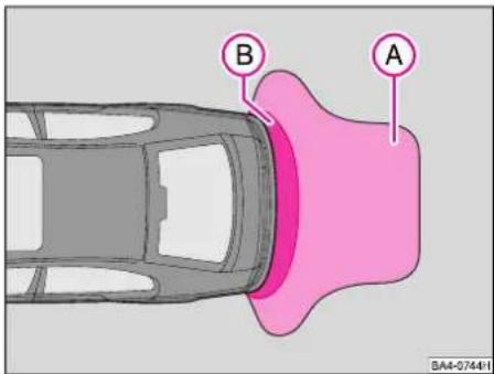
text_image
B A BA4-07441Ultrasonic sensors in the rear bumper signal to you the distance from the rear bumper to an obstacle.
The parking aid is actuated automatically when the ignition is switched on and reverse gear is engaged.
The clearance warning begins when reversing at a distance of about 1.6 metres from the obstacle (area A). The interval between the warning signals becomes shorter as the clearance is reduced.
A continuous tone sounds from a clearance of just 0.3 cm (area B) - danger area. Stop immediately!
Warning
■The parking aid is not a substitute for the driver's proper attention. The driver continues to be responsible for handling the car when parking and carrying out similar manoeuvres. ■Before reversing, nevertheless ensure whether there is a small dimension object behind your car, for example a stone, narrow post, trailer drawbar etc. Such an obstacle might be beyond the detection range of the sensors.
Notes
■The parking aid is not active when towing a trailer.
■If the continuous signal sounds for about 5 seconds after switching on the ignition and engaging the reverse gear, and there is no obstacle behind the car, this indicates a system fault. Please contact a Škoda Dealer.
■It is important that the sensors are clean and free of ice if the system is to operate properly.
Excess speed signal\*
If the car is driven at a speed of more than 120 km/h, an audible signal sounds as a warning. This audible signal switches off again once the speed of the car drops below this speed limit.
This feature applies only to certain export countries.
CONTROLS AND EQUIPMENT
Instruments

text_image
1 2 3 5 0:04 6 STOP OIL PRESS. STOP MOTOR! SERVICE HANUAL PKN0432 - 17 0.8 4 BA4-0673HThe positioning of the instruments depends on the particular model and engine version.
1 - Rev counter 48
2 - Coolant temperature gauge ..... 48
3 - Fuel gauge 49
4 - Speedometer, trip counter,
Service interval display .... 49
5 - Digital clock .... 50
Multi-function display* .... 50
6 - Information display* 53
1 - Rev counter
The needle of the rev counter must not move into the red zone of the scale on any account.

Changing up in good time helps to save fuel and keeps the noise down.
Change down to the next lower gear before the engine no longer runs smoothly.
Avoid high engine revs during the running-in period - see page 117.
2 - Coolant temperature gauge

The gauge starts to work when ignition is switched on, but it takes some time before the needle reaches its final position.
Cold range
The needle is in the bottom range of the scale. Avoid high revs and high engine loads.
Normal range
When the car is driven normally, the needle should settle in the middle range of the scale.
The needle may also move further to the right if the engine is driven at high loads and at high ambient temperatures, but the warning lamp for the coolant temperature must not flash.
If the warning lamp flashes, refer to the information on page 58.
3 - Fuel gauge

The gauge starts to work when the ignition is switched on.
The fuel tank holds about 55 litres (4x4* - 63 ltr.).
If the warning lamp comes on, there are still about 7 litres of fuel in the fuel tank.
4 - Speedometer
During the running-in period, refer to the instructions on page 117.
The speedometer range depends on the engine power output.
Odometer
The upper counter registers the total distance driven, and the bottom counter the short trips (trip counter).
The figure after the point in the lower counter indicates 100 m or 1/10 mile.
The trip counter can be zeroed by pressing the knob (below the speedometer).
For your own safety, do not attempt to zero the counter when driving.
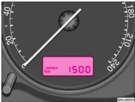
text_image
service km 1500 SA4-0690HService interval display
If the due date of an inspection is reached, the following text appears in the trip counter display* or in the information display* (see page 53) ^1) :
„Service km 1500“ or
The km figure is reduced in steps of 100 km prior to the service inspection.
If the due date for inspection is reached, the flashing readout „service“ or „service now“ appears in the display.
The service message disappears about 20 seconds after starting the engine. You can also switch to the trip counter display by pressing the reset knob (for more than 0.5 seconds).
It is recommended to have repair and service work carried out only in a Škoda Dealership.
The Škoda Dealership which carried out the service resets the service interval display after completion of the work.
It is also possible to reset the service interval display with the reset knob of the trip counter as follows:
■Switch off the ignition and press the reset knob of the trip counter below the speedometer and hold.
■Switch on the ignition and release the reset knob. The message „service“ or „service now“ appears in the display. ^1)
■Turn the knob for setting the clock to the right until the message is reset.
CONTROLS AND EQUIPMENT
Note
■Do not reset the readout between service intervals, otherwise an incorrect readout will be displayed.
■The information is retained even if the vehicle battery is disconnected.
■If the instrument cluster is replaced during repairs, it is necessary to reset the service interval display. This should be done by a Škoda Dealership.
It is not recommended to reset the service interval display yourself otherwise this may result in incorrect settings and thus in possible faults in the vehicle.
After resetting the service interval display on models fitted with LongLife Service*, the service messages are displayed in the same way as on models not fitted with LongLife Service.
For this reason we recommend having the service interval display reset in a Škoda Dealership. The service interval display is correctly reset by the Škoda Dealership using a diagnostic tester.
Fault display
If there is a fault in the instrument cluster, „def“ appears continuously in the display panel of the trip counter. The fault should be rectified as soon as possible by a Škoda Dealer.
5 - Digital clock
A knob is provided at the bottom right of the rev counter for setting the time.
■The hours can be set by turning the knob to the left.
■The minutes can be set by turning the knob to the right.
Warning
■Always withdraw the key from the ignition lock when leaving the car - even if only for a short time.
■For safety reasons, do not attempt to set the time when driving. When setting the time, the button should only be turned and not pressed otherwise the clock may be damaged.
5 - Multi-function display\*
The information appears in the rev counter display or in the information display - see page 53 - depending on the vehicle equipment.
The multifunctional display shows in addition to the time a range of further information:
■Outside temperature
■Range
■Current fuel consumption level
■Average fuel consumption
■Counter for the distance driven
■Average speed
■Driving time
■Time of day

natural_image
Interior view of a car dashboard with steering wheel, dashboard panel, and control buttons (no visible text or symbols)The function selector switch and the Reset button are located in the handle of the windscreen wiper stalk.
The functions are displayed one after the other by repeatedly pressing the top or bottom side of the function selector switch with the ignition on.
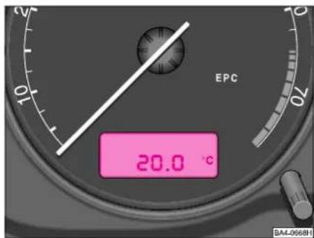
text_image
EPC 20.0 °C SA4-0668HWhen the ignition is switched on, the display switches to the function which had been selected before switching off the ignition.
If the battery is disconnected for any reason, both memories are erased.

text_image
EPC 5.3 x 100km 20.0 °C 05 BA4-0648HExample of readout on models fitted with large information display*
CONTROLS AND EQUIPMENT
The memories
The system is equipped with two memories which operate automatically:
A single trip memory 1
collates the following trip data from the moment the ignition is switched on until it is switched off: Travelling time, distance travelled and quantity of fuel consumed.
This information is used to calculate the average driving speed and the average fuel consumption.
If the trip is continued within 2 hours after switching off the ignition, the additional information is also included in the calculation. The memory is automatically erased if the trip is interrupted for more than 2 hours.
A total trip memory 2
collates the trip data of any desired number of individual trips up to a total of 100 hours travelling time, 10000 km distance and 1000 litres of fuel consumed. These trip data are used for calculating the average fuel consumption and speeds achieved during all the individual trips.
If one of the figures stated is exceeded, the memory is erased and the calculation starts from the beginning again. Contrary to the single journey memory, this memory is not erased after a break in the journey of more than 2 hours.
Retrieving information
To retrieve the information, select the memories by pressing the „Reset“ button:
- Single trip memory - 1
- Total trip memory - 2
The following data can be displayed:
■Driving time
■Distance driven
■Average speed
■Average fuel consumption
Erasing the memories
The memories can be reset to zero by pressing the „Reset“ button for at least 1 second.
Displaying
After switching on the ignition, the last readout selected is displayed.
Ambient temperature

The correct ambient temperature is displayed only after 5 minutes. If the car is not moving or travelling only at a very low speed, the temperature indicated may be slightly higher than the actual ambient temperature because of the heat radiated by the engine.
Warning
If the ambient temperature display is used as an ice warner, do not forget that black ice may also be present on the road surface even at temperatures above 0^ C. A snow flake symbol is displayed in addition (depending on vehicle equipment).
Range
This readout indicates the distance which the vehicle can still travel with the actual level of fuel in the fuel tank. The figure is based on the calculation of the average fuel consumption for the last 50 km. If the display is reset (after disconnecting and reconnecting the battery), the vehicle should be driven 50 km in order to display the relevant figure.
Momentary consumption I/100 km
The readout indicates the actual consumption in ltr./100 km.
The fuel consumption is calculated in two-second intervals. If the vehicle is not moving, the fuel consumption is displayed in l/h.
Average fuel consumption ∅ I/100 km
What is indicated is the average consumption not the actual consumption at the time of reading the display.
The average fuel consumption is indicated after switching on the ignition or erasing the memory being used, after a distance of about 300 metres. Up to this point dashes are displayed instead of a figure.
Single trip memory 1 - what is displayed is the average fuel consumption of the particular individual trip.
Total trip memory 2 - what is displayed is the average fuel consumption which has been achieved during all individual trips - see also „Total trip memory“.
Note
The quantity of fuel consumed is not indicated.
Distance
km
The remarks made under „Driving time“ also apply in the same way to „Distance driven“. The maximum distance displayed is 9999 km.
Average speed
∅ km/h
The remarks made under „Average fuel consumption“ also apply here in the same way.
Time no symbol
The time is also displayed even if the ignition is switched off. The clock is set with the rotary knob - see „Digital clock“, page 50.
Driving time

1 - the driving time which has elapsed since ignition was switched on or since memory was deleted - refer to single trip memory, page 52.
2 - the total driving time of all individual trips - refer to total trip memory, page 52.
The maximum time displayed in both switch positions is 99 hours and 59 minutes. If this figure is exceeded, the display starts again at zero.
6 - Information display\*
When the ignition is switched on and the vehicle is driven, certain functions and the vehicle status are constantly checked.
Operational faults or repairs which must be dealt with immediately, or further information, is signalled by means of a red and yellow illuminated symbol in the dash panel insert in line with the priority. If the symbol lights up, an audible signal also sounds.
In addition, the information and warning texts appear in the display - see page 56.
Texts or instructions for driver, depending on the version, can be displayed in one of the language versions:
English, French, Italian, Spanish, Portuguese, German, Czech.
The appropriate language version can be selected in a Škoda Dealership.
CONTROLS AND EQUIPMENT
The following information (depending on the vehicle equipment) appears in the large or small display:
- Information and warning texts
- Information of MFD - see page 50
- Warning symbols or warning lamps - see page 56
- Selector lever position of automatic gearbox - see page 39
- Information of service interval display - see page 49
- Information of navigation system

text_image
EPC :05 PLEASE REFUEL RN0432 BA4-066SH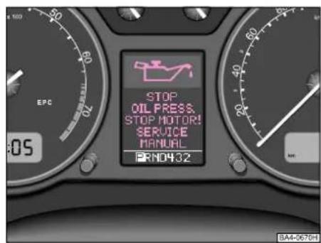
text_image
STOP OIL PRESS. STOP MOTOR! SERVICE MANUAL BRND432 EPC 05 BA4-0676HExample of readout in small display* Example of readout in large display*
Navigation system\*

natural_image
Interior view of a car dashboard with a black seatbelt and directional arrow (no text or symbols visible)Operating menu of display \*
Select the menu in the large information display by pressing the top part of the rocker switch on the windshield wiper lever in direction of arrow (for more than 1 second) - see illustration.
You can scroll through the individual displays with the rocker switch. When you release the switch, the selected information is displayed.

natural_image
Interior view of a car dashboard with a pink arrow pointing to the left side (no visible text or symbols)Navigation system
On models fitted with the navigation system, it is possible to switch between the following settings by pressing the switch in the handle of the windscreen wiper lever (for more than 2 seconds):
■Navigation information
Information of MFD
If the navigation system is operating, priority is given to displaying the information and warning texts in the information display.
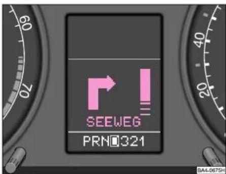
text_image
SEEWEG PRNO321 BA4-0675HOperation of the navigation system is described in separate operating instructions to be found in the on-board literature.
CONTROLS AND EQUIPMENT
Indicator/warning lights

text_image
1/min x 100 30 50 90 130 1/2 1/1 EPC 0:04 km/h 60 80 100 120 20 40 60 80 100 120 17.1 0.8 BA4-0741HThe position of the indicator/warning lights depends on the model and engine version. You will find the symbols presented in the description which follows on or at the corresponding indicator/warning lights in the instrument cluster.
When certain warning lights come on, this is accompanied by an audible signal. A text may also be shown in the information display* - see previous chapters.
Warning
If you do not pay attention to the warning lights coming on and the corresponding descriptions and warning notes, this may result in severe body injuries or major vehicle damage.
The engine compartment of your car is a hazardous area.
There is a risk of injuries, scalding, accidents and fire when working in the engine compartment, e.g. inspecting and replenishing oil and other fluids.
Absolutely pay attention to the warning notes - see page 137.
Turn signal system

The right or left indicator light flashes when switching over the turn signal light upwards or downwards.
If a turn signal fails, the warning light flashes twice as fast. This does not apply when towing a trailer. Both warning lights flash when the hazard warning system is switched on.
Main beam

The warning light comes on when main beam is switched on or when the headlight flasher is used.
Further details are given on page 67.
Airbag system\*

The warning light comes on for a few seconds when ignition is switched on.
If the lamp does not go out or if it comes on again when driving, there is a fault in the system. This is also valid if the warning light does not come on when switching on the ignition. Further information see page 103.
Text in the information display*: AIRBAG FAULT (fault at airbag)
The operational readiness of the airbag system is monitored electronically, also on deactivated front passenger airbag or side airbag.
If the front or side airbag was deactivated with the switch in the glove box:
- the warning light comes on for 3 seconds when the ignition is switched on;
- the deactivation of the airbag is signaled by the warning light Airbag OFF coming on in the front interior light
Warning
If a fault exists, have the airbag system checked immediately by a Skoda Dealer. Otherwise, there is a risk of the airbag or the seat belt not being activated in the event of an accident.
Trailer turn signal system\*
◇1◇
The warning light flashes if the turn signal system is operated when towing a trailer. If a turn signal light of the trailer or towing vehicle fails, the warning light does not flash.
Low beam
30
The warning light comes on after the low beam is switched on - see page 82.
Fog lights\*
±0
The warning light comes on when the fog lights are switched on.
Rear fog light
0‡
The warning light comes on when the rear fog light is switched on.
Testing engine electronics\* EPC
(fitted only to certain engines)
The warning light comes on for a few seconds when the ignition is switched on.
If the warning light does not go off or comes on or flashes when driving, this indicates a fault in the engine electronic system. A program stored in the engine control unit makes it possible to continue driving with certain restrictions - contact a Škoda Dealer for professional assistance.
Glow plugs
00
(diesel engines only)
If the engine is cold, the warning light comes on when the preglow position „2“ (ignition on) is switched on - see page 43. If the warning light does not come on, there is a fault in the glow plug system - contact a Škoda Dealer for assistance. After the light goes out, start the engine rightaway. If the engine is warm, the glow plug warning light does not come on - the engine can be started straightaway.
If the warning light flashes when driving, there is a fault in the system.
Contact a Škoda Dealership for professional advice.
CONTROLS AND EQUIPMENT
Coolant temperature, coolant level

The warning light comes on for a few seconds after switching on the ignition.
On vehicles with information display, the warning light does not come on after switching on the ignition, only if a fault exists or a lack or coolant.
If the warning light does not go off after this or flashes when driving, either the coolant temperature is too high or the coolant level is too low.
Text in the information display*: STOP CHECK COOLANT SERVICE MANUAL.
An audible warning signal then sounds (peep signal 3 times).
If this happens, stop the car and switch off the engine; check the coolant level and top up coolant if necessary.
If the warning light comes on, although the coolant is at the correct level and the fan fuse is in proper order, do not drive any further. The engine must then also not run in neutral. Contact a Škoda Dealer for professional assistance.
Warning
■Take care when opening the coolant expansion tank. When the engine is hot, the cooling system is pressurized - risk of scalding! Allow the engine to cool down, therefore, before unscrewing the cap.
■Do not touch the fan! The fan may switch on suddenly - even if the ignition is switched off.
If the coolant is at the correct level, the rise in temperature may be caused by a failure of the radiator fan. Check the fuse of the radiator fan and renew if necessary - see page 167.
If the warning light does not go out although the coolant is at the correct level and the fan fuse is in proper order, do not drive any further. Contact a Škoda Dealer for professional assistance.
Further information is provided on pages 137 and 142.
Brake wear indicator\*

If this warning light comes on, contact a Škoda Dealer to have the brake pads checked.
An audible warning signal sounds (single peep signal).
In view of the fact that the brake wear indicator monitors only the front brake pads, it is recommended to also have the rear brake pads or linings inspected.
Fuel level

The warning light comes on and remains on if there are only about 7 litres of fuel in the tank.
An audible warning signal sounds (1 beep).
Engine oil

Warning light shows red (engine oil level too low)
The warning light comes on for a few seconds when the ignition is switched on.
On vehicles with information display, the warning light does not come on after switching on the ignition, only if a fault exists or a shortage of oil.
If the warning light does not go out after a few seconds or comes on when driving, stop the car and switch off the engine, check oil level and top up oil if necessary – see page 136.
Text in the information display*: STOP! OIL PRESSURE STOP ENGINE! SERVICE MANUAL.
An audible warning signal sounds (peep signal 3 times).
If the warning light comes on although the oil is at the correct level, do not continue driving. The engine must also not be run at idling speed in this case. Contact a Škoda Dealership for professional advice.
Warning
The oil pressure light is not an oil level indicator! One should therefore check the oil level at regular intervals, preferably after every refuelling stop.
Warning light lights up yellow\* (oil in the engine is too low)
If the warning light lights up yellow, the quantity of oil in the engine is probably too low.
Check as soon as possible the oil level or top up with engine oil - see page 140.
An audible warning signal sounds (3x beeps).
Text in the information display*: CHECK OIL LEVEL.
Models fitted with LongLife Service: The oil level warning is reset when the bonnet is opened. If the engine oil is not replenished, the warning appears once again after driving about 100 km.
Yellow warning light flashes\* (engine oil level gauge faulty)
If a fault occurs at the engine oil level gauge, this is indicated by an audible signal and by the warning light flashing several times.
Text in the information display*: OIL SEN- SOR WORKSHOP.
Have the engine inspected without delay by a Škoda Dealership.
CONTROLS AND EQUIPMENT
Opening doors\*

If a door is open, this is indicated by this warning light.
Vehicles with information display
As an additional warning signal, a peep sounds if the car is driven at a speed of more than 6km/hour and if the door or the luggage compartment door is open.
Washer fluid level\*

The warning light comes on if the washer fluid level is too low. Top up washer fluid - see page 151.
An audible warning signal also sounds (single peep signal).
Bulbs\*

This warning light comes on if the bulb of the luminous element is faulty during:
■Operation of brakes (brake light)
■Malfunction of illumination (low beam (or fog light)
An audible warning signal also sounds (single peep signal)
Testing engine electronics\*

The warning light comes on when the ignition is switched on.
If the warning light does not go out after starting the engine, or comes on or flashes when driving, this indicates a fault in the engine electronics system or in systems which influence exhaust emissions. A programme stored in the engine control unit makes it possible to continue driving with certain restrictions - contact a Škoda dealer for professional help.
Electronic stability program (ESP)\*

The warning light comes on for a few seconds when the ignition is switched on.
The ESP system also includes the traction control system (TCS).
The light flashes when driving if the system has activated a control cycle.
The warning light will come on and remain on if the system is switched off or if a system fault exists.
As the ESP system operates in combination with the ABS, EDL and EBC, the ESP warning light also comes on if the ABS system fails.
Further details are given on pages 84 and 122 - 124.
Traction control system (TCS)\*

The warning light comes on for a few seconds when the ignition is switched on.
The light flashes when driving if the system has activated a control cycle.
The warning light will come on and remain on if the system is switched off or if a system fault exists.
As the TCS system operates in combination with the ABS, EDL and EBC, the TCS warning light also comes on if the ABS system fails.
Further details are given on pages 65 and 122 - 124.
Anti-lock brake system (ABS)\*

The warning light monitors the ABS, or ABS and EDL* system.
The ABS warning light should come on for a few seconds when the ignition is switched on. If the ABS warning light does not go off after a few seconds, if it does not come on at all, or comes on when driving, the system is not operating properly. The car is braked in this case without operation of the ABS; only the normal brake system then operates. Contact a Škoda Dealer as soon as possible and adapt your style of driving to the fault which exists for you cannot know the extent of the problem.
Electronic differential lock (EDL)\*
The EDL system operates in combination with the ABS. A failure of the EDL system is indicated by the ABS warning light coming on. You should then contact a Škoda Dealer without delay.
Models fitted with ESP are equipped with electronic differential lock (EDL).
If a major fault is present in the ABS system, an audible warning signal also sounds (3 peeps). Further information on the ABS and EDL systems is given on pages 122 and 124.
Electronic immobiliser

When the ignition is switched on, a data harmonization is performed between key and control unit. If the data exchanged are correct, this is confirmed by the warning light coming on for a few seconds.
If an unauthorized car key (e.g. forged key) has been used, the warning light changes to a continuous flashing light. It is then no longer possible to start the car - see page 7.
Brake fluid level

The warning light comes on for a few seconds after switching on the ignition.
Warning
If the warning light comes on when the ignition is switched on or when driving, there is a fault in the brake system. Contact the nearest Škoda Dealer without delay and have the brake system inspected.
An audible warning signal sounds (3 peeps).
You can drive on carefully to the nearest Škoda Dealer but allow for higher pedal pressures, longer braking distances and greater idle travel of the brake pedal.
The warning light also comes on when the handbrake is applied.
Charge indicator

The warning light comes on when the ignition is switched on. It should go out when the engine is started.
If the warning light comes on when driving or does not go out after the engine has started, stop the car and switch off the engine. Check the ribbed belt.
If it is loose or broken, do not drive any further. The belt has to be tensioned or replaced.
If the ribbed belt is in proper order and the warning light nevertheless comes on, it is possible to drive on to the nearest Škoda Dealer. In this case, the battery will not be charged; switch off all unnecessary electrical components in the vehicle.
An audible warning signal sounds (single peep signal).
Seat belt warning system\*

This warning light comes on to request the driver to fasten the seat belt.
If the driver's belt is not fastened, an audible warning signal sounds for 6 seconds.
CONTROLS AND EQUIPMENT
Switches

text_image
0 1 2 3 A B BA4-0713HLight switch
Notes
■The position of the switches differs on right-hand drive vehicles. The symbols on the switches are, however, the same as on vehicles with left-hand drive.
■Use of the lighting described here is subject to the legal regulations of the country concerned.
■If the side lights are not switched off after withdrawing the ignition key, an audible signal sounds as a reminder as soon as the driver's door is opened.
■The warning signal of the buzzer is switched off by the door contact when the driver's door is closed (ignition off) allowing the car to be parked with the side lights on.
0 - Off
1 - Side lights
3DCE
2 - Low beam

Low beam and main beam operate only if the ignition is switched on.
The headlights are switched automatically to side lights when starting the engine and after switching off the ignition.
For switching the headlights between low beam and main beam and using the head-light flasher - see page 67.
3 - Instrument lighting\*

If the car lights are switched on, the intensity of the instrument lighting can be steplessly varied by then turning this knob.
Warning
Never drive with side lights on - risk of accident!
The side lights are not bright enough to light up the road sufficiently in front of you or to be seen by other oncoming traffic.
Therefore always switch on the low beam when it is dark or when visibility is poor.
Fog lights\*

The fog lights are switched on by pulling the switch into position A.
The fog lights come on if the side lights, low or main beam are switched on.
Rear fog light

The rear fog light is switched on by pulling the switch into position B.
The rear fog light comes on if the low or main beam is selected or if the front fog lights are switched on (depends on the national version). The rear fog light should only be switched on if visibility is poor, because of the risk of dazzling a driver behind.
Notes
■The rear fog light is incorporated in the rear light of the driver's side.
■The electrical system of the towing device fitted for certain countries is designed to automatically switch off the rear fog light of the car when towing a trailer fitted with a rear fog light.

text_image
1 OCTAVIA 2 3 4 5 ESP I/OBA SA4-0592H1 - Hazard warning system
2 - Rear window heater/Exterior mirror heater
3 - ESP/TCS* (The switch applies to the ESP or TCS, depending on the system fitted. See pages 64 and 65 for further information on ESP and TCS.
4 - Thumbwheel for front seat heater*
5 - Remote fuel filler flap released from driver's seat*
1 - Hazard warning system

If the hazard warning system is switched on, all the turn signal lights of the car flash at the same time. The warning light for the turn signals and the warning light in the switch also flash. The system operates even if the ignition is switched off.
2 - Rear window heater

The heating operates only if the ignition is switched on. When the heater is operating, the warning light in the switch comes on.
After the rear window heater is switched on, the heaters of the exterior mirrors are also switched on on models fitted with power windows.
The rear window heater switches off automatically after 20 minutes.
If you press the switch 2 once again, the rear window heater is switched on permanently - the automatic deactivation is thus deactivated.
As soon as the rear window is clear, switch off the heater. The reduced current consumption improves your fuel consumption - see also page 118.
CONTROLS AND EQUIPMENT
3 - Electronic stability program\* ESP
Models fitted with anti-lock brake system (ABS) can be equipped additionally with an electronic stability program (ESP).
The ESP makes it possible to enhance control over the vehicle in situations in which the vehicle is operating at the dynamic limits, such as driving too fast into a curve. The ESP is an extension of the ABS/EBC//TCS/EDL function and reduces the risk of skidding in all road conditions. The system operates over the entire speed of the vehicle in conjunction with the ABS. If a fault develops in the ABS system, the ESP then also does not operate.
The ESP is switched on automatically each time the engine is started. It can be switched off and on, as desired, together with the TCS system, by pressing the pushbutton.
If the system is switched off, the ESP warning light comes on - see page 60.
In exceptional cases where wheel slip is desired, it is beneficial to switch off the ESP system.
For example:
- when driving with snow chains
- when starting off in deep snow or on a loose surface
- when rocking the car free if it has got stuck.
The system should be switched on again after this.
Note
The same tyres must be fitted to all four wheels if the ESP system is to operate properly. Differing rolling circumferences of the tyres can result in an undesirable reduction in engine output.
Repairs on the vehicle (e.g. on engine, braking system, chassis or another combination of wheels and tyres) can influence the function of the ESP.
Operating principle of ESP
The ABS, EBC, EDL, TCS systems are integrated in the electronic stability program. In addition to the data available from these functions, the ESP control unit is also supplied with signals which are transmitted by highly sensitive sensors. What is measured is the spinning rotary motion about the vertical axis of the vehicle, the lateral acceleration of the vehicle, the brake pressure and the steering lock.
Note
The direction selected by the driver is determined with the aid of the movement of the steering and the vehicle speed and constantly compared with the actual behaviour of the vehicle. If variations exist, such as the vehicle beginning to slide, the ESP automatically brakes the wheel in question and reduces engine speed.
The vehicle is again stabilised as a result of the forces acting on the wheel during the braking operation. If the vehicle is oversteering (tending to break away at the rear), it is primarily the outside front wheel which is braked, whereas, if the vehicle is understeering (tending to slide out of the curve), the rear inner wheel is then braked.
Warning
The ESP system is also not able to overcome the physical limits of the vehicle. You should remember this, particularly when driving on slippery and wet road surfaces.
Your style of driving should always be adapted to the condition of the road and the traffic situation. The enhanced safety offered by the ESP must not tempt you to take any risks which compromise your safety.
3 - Traction control system\* TCS
Vehicles fitted with the anti-lock brake system (ABS) can additionally be equipped with a traction control system (TCS).
On front-wheel drive vehicles, the TCS prevents the driven wheels from slipping when the car is accelerated, by reducing the engine output. The system operates in combination with the ABS over the entire vehicle speed range. If a fault develops in the ABS, the TCS is also affected.
The TCS switches on automatically when the engine is started. If desired, the system can be switched off and on by pressing the pushbutton.
If the system is switched off, the TCS warning lamp comes on - refer to page 60.
The TCS should always be switched on in normal driving conditions. It is only beneficial to switch off the system in certain exceptional cases if wheel slip is desired.
For example:
- when driving with snow chains
- when starting off in deep snow or on a loose surface
- when rocking the car free if it has got stuck.
The system should be switched on again after this.
Note
The same tyres must be fitted to all four wheels if the TCS system is to operate properly. Differing rolling circumferences of the tyres can result in an undesirable reduction in engine output.
Repairs on the vehicle (e.g. on engine, braking system, chassis or another combination of wheels and tyres) can influence the function of the ASR.
Warning
Always adapt your style of driving to the condition of the road and the traffic situation. The increased safety offered by the TCS system must not induce you to take risks with your safety.
The traction control system greatly facilitates starting-off, accelerating and climbing hills, or at all makes this possible, even when driving on poor road conditions.
4 - Knurled wheel for seat heating\*

The cushion and backrest of the front seats can be heated electrically when the ignition is on.
The heater can be switched on with the appropriate knurled wheel and regulated as desired.
To switch heating off, turn knurled wheel to the basic position „0“.
Note
Do not switch on the seat heater until after starting the engine. This considerably reduces the drain on the battery capacity.
5 - Releasing fuel filler flap from driver's seat\*

The fuel filler flap opens when the switch is pressed. For further information - see page 127.
CONTROLS AND EQUIPMENT

natural_image
Mechanical component diagram showing a piston and connecting rod assembly with a pink arrow indicating motion (no text or symbols)Emergency release of fuel filler flap
If the remote release at the driver's seat* does not operate properly, it is possible to unlock the fuel filler flap manually:
■Open tailgate, detach the luggage compartment trim on the right and pull off.
■Then, push the locking rod in direction of arrow - see illustration.

natural_image
Close-up of a car dashboard control panel with no visible text or symbols on the dial (pure graphical elements)Headlight range control

If the low beam is switched on, it can be matched exactly to the load of the vehicle with the headlight range control.
■You can turn the knurled wheel until the low beam has been adjusted in such a way that other road users are not dazzled.
The individual headlight beam settings correspond approximately to the following vehicle load:
-- driver, front passenger
I - 5 persons
II - 5 persons and an additional 180 kg in the luggage compartment, in line with the permissible load of the front and rear axles
III - driver and an additional 330 kg in the luggage compartment, in line with the permissible load of the front and rear axles.
Warning
Adjust the headlight beam control, so that the traffic on the opposite side is not dazzled.
Headlights fitted with Xenon bulbs adapt automatically to the load and driving state (e.g. accelerating, braking) when ignition is switched on and when driving.

natural_image
Interior view of a car dashboard with pink control knob and steering wheel (no visible text or symbols)Multifunction switch
The turn signal system only operates if the ignition is switched on.
Right turn signals - lever up
Left turn signals - lever down
When turn signals are operating, the appropriate warning light also flashes - see page 56.
The turn signal lights are cancelled automatically when the steering wheel is moved back into the straightahead position.
High and low beam
If low beam is switched on, press the lever away from the steering wheel. A blue warning light comes on to indicate the high beam setting. To switch over to the low beam setting, pull the lever back into its original position.
Note
On models fitted with xenon headlights*, do not switch on main beam and fog lights at the same time when the car is stationary.
Coming Home Function\*
The function enables the lighting of the low beam for a short time after leaving the vehicle, e.g. for illumination of Coming-Home etc.
Select function
■Switch off light
■Switch off ignition
■Flash with main beam (headlight flasher)
■Open and close door
If the door is open, the light is on for approx. 3 minutes.
If the door is closed, the light is on for approx. 30 seconds
Headlight flasher
Pull lever toward steering wheel as far as the pressure point - the main beam and the indicator light come on.
Note
Use of the signal and lighting systems described is subject to local national regulations.
Parking lights
The parking light can only be switched on if the ignition is off.
Right parking lights - lever up Left parking lights - lever down
Notes
■Use of the parking lights is subject to local national regulations.
■If the lever is not in the middle position after withdrawing the key, an audible signal sounds when the driver's door is opened. The audible signal switches off again as soon as the door is closed.
CONTROLS AND EQUIPMENT
Tempomat (cruise control system)\*
With the aid of this system it is possible to constantly maintain any desired speed from 30 km/h without the driver having to hold his foot on the accelerator pedal.
Warning
Do not use the cruise control system in dense traffic or on a slippery road surface (ice, snow, rain, grit, etc.). If the cruise control system is switched on, do not shift into neutral without depressing the clutch pedal otherwise the engine may overrev. In order to prevent unintentional use of the cruise control system, always switch off the system after use.
Note
On models fitted with an automatic gearbox, the cruise control system is only active in selector lever positions D, 3 and 2. It is not possible to use the cruise control system in selector lever positions P, N, R and 1.

text_image
A B BA4-074D+The system is operated with the sliding switch A and the pushbutton B on the multifunction switch.
Switching on
Move switch A to ON.
Storing a speed
Switch on the cruise control system. As soon as you have reached the desired speed, briefly press pushbutton B in position SET. After pressing pushbutton B in position SET, the car will maintain the speed stored (above 30 km/h [20 mph]) without you having to depress the accelerator.
The stored speed can also be increased in the usual way by depressing the accelerator. When the accelerator is released, the speed is again reduced to the speed previously stored.
This is not the case, however, if the stored speed is exceeded by more than 10 km/h for a period of more than 5 minutes. In such a case, it is necessary to again store the speed.
The speed can be reduced in the usual way - by depressing the brake pedal or the clutch pedal (switches off system temporarily - refer to page 69).
Warning
You must only resume the stored speed if it is not too high for the traffic conditions which exist at that moment.
Changing stored speed
Decelerating
The stored position can be reduced by pressing the pushbutton B in position SET.
The speed of the vehicle is reduced continuously if the pushbutton B is pressed and held in position SET. Release the pushbutton once the desired speed is reached. The speed is then stored.
If the pushbutton is released at a speed below 30 km/h, the speed is not stored and the memory is erased. In this case, the speed of the vehicle must be re-stored with pushbutton B in position SET after accelerating the car to more than 30km/h.
Accelerating
The stored speed can be increased by pushing the switch B in the position RES without operating the accelerator.
The speed of the car is increased continuously if the switch is pressed and held. Release the switch as soon as the desired speed is reached. This speed is then stored.
Switching off system temporarily
Models with manual gearbox
The system is switched off temporarily by depressing the brake pedal or clutch pedal. The system is also switched off by sliding switch A to the right - into position OFF.
The speed which is stored at this moment is retained.
Resuming the stored speed is achieved by releasing the brake pedal or clutch pedal and after pressing the switch B into position RES
Warning
You must only resume the stored speed if it is not too high for the traffic conditions which exist at that moment.
Models with automatic gearbox
The system is switched off temporarily by depressing the brake pedal.
The system is also switched off by sliding switch A to the right - into position OFF.
The speed stored at this moment is retained.
Resuming the stored speed is achieved by releasing the brake pedal or clutch pedal and pressing the switch B into position RES
Warning
You must only resume the stored speed if it is not too high for the traffic conditions which exist at that moment.
Switching off system completely
Models with automatic gearbox
To switched off the system completely, move the switch A fully to the right to OFF.
CONTROLS AND EQUIPMENT
Multifunction steering wheel\*
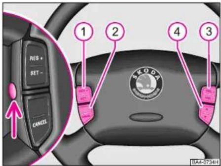
text_image
RES + SET - CANCEL 1 2 4 3 SKODA BA4-0734HWhat is operated with the pushbuttons on the steering wheel depends on the equipment fitted to the car.
Pushbuttons 1, 2, 3 and 4 are used to operate the main functions of the cruise control and the radio system. Please also refer to the additional information provided in the corresponding operating instructions.
Press the button (refer to arrow) when the lights are switched on in order to illuminate the buttons on the steering wheel.
Operating cruise control
The cruise control is switched on by moving switch A to ON (refer to ill. on p. 68).
The system is switched off completely by moving switch A fully to the right to the OFF position (refer to ill. on p. 68).
Storing speed
Switch the cruise control on. As soon as you have reached the speed you wish to maintain, briefly press pushbutton 1 in the position SET-. The car maintains the stored speed without the need to operate the accelerator pedal. Changing a stored speed - see page 68.
Changing stored speed
The stored speed can be reduced by pressing pushbutton 1 in position SET-. If the button is pressed and held, the speed reduces continuously. Once you have reached the speed you wish to maintain, release the button. The desired speed is then stored.
The stored speed can be increased by pressing pushbutton 1 in position RES+. If the button is pressed and held, the speed increases continuously. Once you have reached the speed you wish to maintain, release the button. The desired speed is then stored.
Switching off cruise control temporarily
The cruise control is switched off temporarily by pressing pushbutton 2 in the position CANCEL.
The stored speed is resumed by pressing pushbutton 1 in position RES+.
For further versions of switching off the cruise control temporarily - refer to p. 69.
Warning
The stored speed must only be resumed if it is not too high for the traffic conditions which exist at that moment.
Operating radio system and CD changer
The radio system is operated with push-buttons 3 and 4.
Pushbutton 3 with positions VOL+ and VOL-:
The volume of the radio system, cassette player, CD changer and recorder of traffic reports is increased or reduced by pressing the button in the appropriate position.
Pushbutton 4 with positions indicated by the two arrows:
Radio system: You can search up or down for radio stations in accordance with the frequency search by pressing the button in the appropriate position.
Cassette player: You can operate the fast forward or return by pressing the button in the appropriate position.
CD changer: You can select preceding or subsequent sections of music by pressing the button in the appropriate position.
CONTROLS AND EQUIPMENT
Windscreen wiper and washer system
Traffic information memory* (RDS): You can play preceding or subsequent traffic information bulletins by pressing the button in the appropriate position.
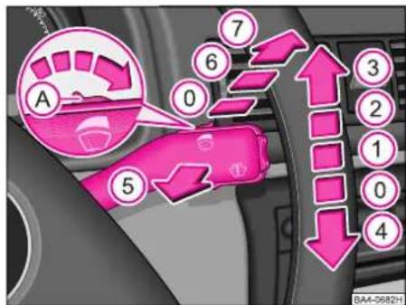
text_image
A 0 5 6 7 3 2 1 0 4 BA4-0682HThe windscreen wipers and windscreen washer system only operate when the ignition is switched on.
In frosty weather, check that the wiper blades are not frozen to the glass before switching the wipers on for the first time.
Notes
■Topping up washer fluid - see page 151.
■Changing windscreen wiper blades - see page 152.
Windscreen
■Flick wipe
Lever in position 4.
■Intermittent wipe
Lever in position 1.
Four different intermittent settings can be selected with the intermittent wipe switch A.
■Slow wipe
Lever in position 2.
■Fast wipe
Lever in position 3.
■Automatic wipe/wash
Pull lever toward steering wheel (position 5); the windscreen wipers and washer system operate.
Letting go of the lever will cause the windscreen wash system to stop and the wiper to continue for another 1 - 3 wiper strokes (depending on the period of spraying of the windscreen).
The wiper wipes once again 5 seconds after the last wiper stroke, in order to wipe the last drops from the windscreen.
Rain sensor\*
Lever in position 1.
The wipe intervals are controlled automatically by the rain sensor depending on how much rain is falling.
The sensitivity of the rain sensor can be set individually with switch A.
CONTROLS AND EQUIPMENT
After the ignition is switched off, you have to re-activate the rain sensor. To do this, move the lever into position 0 and then back again into position 1.
Warning
Do not use the windscreen washer system at low temperatures, without heating the windscreen beforehand. Otherwise the window cleaner could freeze on the windscreen and restrict the view to the front.
Headlight washer system\*
When the side lights, low beam or main beam are switched on, the headlight lenses are also washed every time the windscreen is washed.
There is a time delay of about 3 second after operating the lever (position 5) before the headlights are washed.
Stubborn dirt (such as insect residues) should be removed from the headlight lenses at regular intervals, for example when refuelling.
In winter, also clean off any snow on the washer nozzles or use de-icing spray to remove the ice to ensure proper operation.
Rear window
■Intermittent wipe
Stalk in position 6.
The wiper operates every 6 seconds.
■Automatic wash/wipe\*
Push down stalk away from steering wheel into position 7. The washer system and the wiper operate so long as the stalk remains in this position.
Release stalk. The washer system no longer operates and the wiper performs a further 1 to 3 sweeps (depending on the length of the washing operation).
The stalk remains in position 6 after being released.
■Switching off intermittent wipe
Stalk in position 0.
Heating and ventilation

text_image
BA4-059SH A B C D TIM 1 2 3 4 5 6 FL SCAN BA4-059SHControls
Rotary control A - temperature selection clockwise - increases heat output anti-clockwise - decreases heat output
Rotary switch B - blower and shutting-off air supply
The quantity of air which flows through the heater is regulated with rotary switch B. The air supply can be regulated in four stages.
The blower is switched off in position 0. To switch off the fresh air supply press button D, see below. The air supply should only be switched off for a short time as the windows may mist up.
Rotary control C - air distribution
The air distribution to the vents is regulated with the rotary control.
Pushbutton D - recirculated air mode
The recirculated air mode in the car is switched on by pressing the button D.
The symbol on the pushbutton comes on. Switch off by once again pressing the pushbutton.
We recommend the recirculated air mode should only be selected for a short time, however, as no fresh air is supplied, the windows may mist up.
For safety reasons, it is not possible to press pushbutton D if the rotary control C is in the position ....

or is close to this position.

text_image
E F G 1 1 1 1 1 2 2 3 3 4 4 5 5 5 5 BA4-0706HAir vents
Heated or non-heated fresh air flows out of all the vents depending on the position of the rotary control A.
The air distribution to the vents is regulated with the rotary control C.
The vents 3 and 4 can also be closed and opened individually with the vertical thumb-wheel:
Vent closed - vertical thumbwheel of air outlet vent in position E and G
Vent open fully - vertical thumbwheel of air outlet vent in position F.
It is also possible to alter the direction of the air flow with the horizontal and vertical thumbwheels of the air outlet vents 3 and 4.
The rear footwell vents are regulated together with the vents 5.
On models with another type of dash panel, the air vents are regulated in a similar way.
Defrosting windscreen and side windows
■ Rotary switch B to position 4
■ Rotary control A fully to the right and C to ....
■Close vents 3.
■Warm air can be directed additionally to the side windows through vents 4.
CONTROLS AND EQUIPMENT
Demisting windscreen and side windows
If the windows mist up due to high air humidity (e.g. when it is raining) we recommend the following settings:
■ Rotary switch B to position 2 or 3
■ Rotary control A, if necessary, in heating range
■ Rotary control C to ....
■Close vents 3
■Warm air can additionally be directed to the side windows through vents 4.
Heating up interior quickly
■ Rotary switch B to position 4
■ Rotary control A fully to the right
■ Rotary control C to ....
■Open vents 3 and 4
■Switch over to recirculated air with pushbutton D (air conditioning off)
Heating interior comfortably
If the windows mist up due to high air humidity, e.g. when it is raining, we recommend the following settings:
■ Rotary switch B to position 2 or 3
■ Rotary control A, if necessary, in heating range
■ Rotary control C to ....
■Rotary control C, depending on desired air distribution, to....
or to ....
■Close vents 3
■Open vents 4
Ventilation (fresh air mode)
At the following settings, unheated fresh air flows out of vents 3 and 4:
Pushbutton D must not be set to „recirculated air“
■ Rotary switch B to desired position
■ Rotary control A fully to the left
■ Rotary control C to ....
■Open vents 3 and 4
The rotary control C can also be turned into other positions, if desired.
General notes
■The air inlet in front of the windscreen should be kept free of ice, snow and leaves to ensure the heating and ventilation system can operate properly.
■All the controls can be set to any desired intermediate position, except blower switch B in the blower positions 1 - 4.
■The blower should always be set to run when driving at low speeds in order to prevent the windows from misting up.
■The heat output depends on the coolant temperature - full heat output is therefore only available when the engine is warm.
■The stale air flows out of the car through the vent openings behind the right side trim panel of the luggage compartment.
Air conditioning\*

text_image
A B C D E AC BA4-0594HThe air conditioning system is a combined cooling and heating system which offers maximum comfort during all seasons of the year.
The air conditioner operates only when the engine is running, at an ambient temperature above about +5 °C and the blower speed between 1 and 4.
If the air conditioning system is operating, this reduces not only the temperature inside the car but also the air humidity.
This enhances the comfort of the car occupants if the humidity of the ambient air is high.
Controls
On models with another type of dash panel, the air vents are regulated in a similar way.
Rotary control A - temperature selection clockwise - increases heat output anti-clockwise - decreases heat output
Rotary switch B - blower
The air flow can be regulated with the rotary switch B.
The air flow can be set in four stages.
Blower and air conditioner are switched off in position 0. Pushbutton E (recirculated air mode) should be operated to prevent polluted outside air (odours) entering the car.
Rotary control C - air distribution
Distributes air to the air outlet vents.
CONTROLS AND EQUIPMENT
Pushbutton D - switching air conditioner on and off
The system can be switched on by pressing the button D only when the engine is running.
An indicator light in the pushbutton comes on when the air conditioner is operating.
The air conditioner is switched off by again pressing the pushbutton.
Pushbutton E - recirculated air mode
The recirculated air mode in the passenger compartment is switched on by pressing the pushbutton E.
The indicator light in the pushbutton comes on.
The recirculated air mode is switched off by again pressing the pushbutton.
The recirculated air mode can be selected with and without the air conditioner. The recirculated air mode must only be selected for a short time, however, as no fresh air is supplied to the interior and the windows may mist up if the air conditioner is switched off.
Pushbutton E cannot be pressed if the rotary control C
is in the position.... or close to this position.

text_image
6 7 8 1 1 1 1 1 2 3 4 5 5 5 5 BA4-0707HAir vents
Heated or non-heated fresh or cooling air flows out of all the opened vents depending on the position of the rotary controls A, B, C and pushbuttons D and E.
The vents are controlled with the rotary control C.
The vents 3 and 4 can also be closed and opened individually with the vertical thumb-wheel:
Vent closed - vertical thumbwheel of air outlet vent in position 6 or 8
Vent open fully - vertical thumbwheel of air outlet vent in position 7.
It is also possible to alter the direction of the air flow with the horizontal and vertical thumbwheels of the air outlet vents 3 and 4.
The rear footwell vents are controlled together with vents 5.
Defrosting windscreen and side windows
■ Rotary switch B to position 4.
■ Rotary control A fully to the right and C to ....
■Close vents 3.
■Open vents 4.

Heating interior comfortably
Once the windows are clear and the desired interior temperature has been reached, we recommend the following settings:
■ Rotary switch B to position 2 or 3
■ Rotary control A to desired heat setting
■Rotary control C, depending on desired air distribution, to....
■If the windscreen mists up, rotary control C to ....


or to
■Close vents 3.
■Open vents 4.
Heating up interior quickly
■ Rotary switch B to position 4
■ Rotary control A fully to the right
■ Rotary control C to ....
■ Open vents 3 and 4.
■ It is recommended to press pushbutton E.
Optimally cooling interior
■ Rotary switch B to position 2 or 3 (optimal settings for cooling), or position 4 for rapidly cooling interior.
■ Rotary control A fully to the left. The temperature can be increased, as desired, by turning to the right.
■ Rotary control C to ....
■ Open vents 3 and 4.
■Press pushbutton D.
■ It is recommended to set vents 3 and 4 so that the air flows up over the heads of the occupants.
In this operating mode, air is drawn in from outside and cooled.
Maximum cooling
■Close all windows and sliding/tilting roof
■ Rotary switch B to position 4
■ Rotary control A to the left
■ Rotary control C to ....
■Open vents 3 and 4

■Switch on air conditioner by pressing pushbutton D
■Switch on recirculated air mode by pressing pushbutton E
In this operating mode, air is extracted from the interior and cooled (recirculated air mode). The recirculated air mode should only be selected for a short time as no fresh air flows in from the outside.
Do not smoke in the car if the recirculated air mode setting is selected.
CONTROLS AND EQUIPMENT
Ventilation (fresh air operation)
With the following settings, unheated fresh air flows out of vents 3 and 4:
■Switch off air conditioner by pressing pushbutton D
■Switch off recirculated air mode by pressing pushbutton E
■ Rotary switch B to desired position
■ Rotary control A fully to the left
■ Rotary control C to ....
■Open vents 3 and 4
If desired, the rotary control C can also be turned into other positions.
General notes
If the air conditioning is switched on, air may flow out of the vents at a temperature of as low as +5 °C in certain conditions. Lengthy periods sitting in the car and irregular distribution of the air flow from the vents (in particular in the leg area) and large temperature differences, e.g. when getting out of the car, may result in more sensitive persons suffering chills.
■For this reason, please follow the instructions presented in this chapter.
■If the ambient temperature is high and the air very humid, condensed water may drip off the evaporator and form a puddle under the vehicle. This is quite normal and does not indicate a leak.
■All the controls can be set to any desired intermediate position except rotary switch B (in the range of positions 1 to 4) and the pushbuttons D and E.
Using air conditioner economically
■In the cooling mode, the compressor of the air conditioner draws power from the engine and thus affects the fuel consumption.
■If the inside temperature is very high after the car has been parked in the sun, it is recommended to open doors or windows briefly to enable the hot air to escape.
■The air conditioner should not be switched on during a journey if the windows are opened.
■If the desired interior temperature can be reached without switching on the air conditioner, it is better to select the fresh air mode.
■If the air conditioning system has not been switched on for a lengthy period, odours may be produced at the evaporator because of deposits. Switch on the air conditioning system at least once a month, also during the cold season of the year, to the maximum blower speed in order to remove such odours. At the same time open a window.
Climatronic (automatic air conditioning)\*
Controls
Pushbuttons
Display panels
1 - Defrosting windshield
2 - Display of blower stage
3 - Display of ambient temperature
If the Climatronic is switched off at pushbutton 11. OFF appears here in place of the entire display.
4 - Display for defrosting windshield
5 - Display for recirculated air position
6 - Display for direction of air flow
7 - Display of selected interior temperature
8 - Display AUTO (automatic mode), ECON (cooling system OFF)
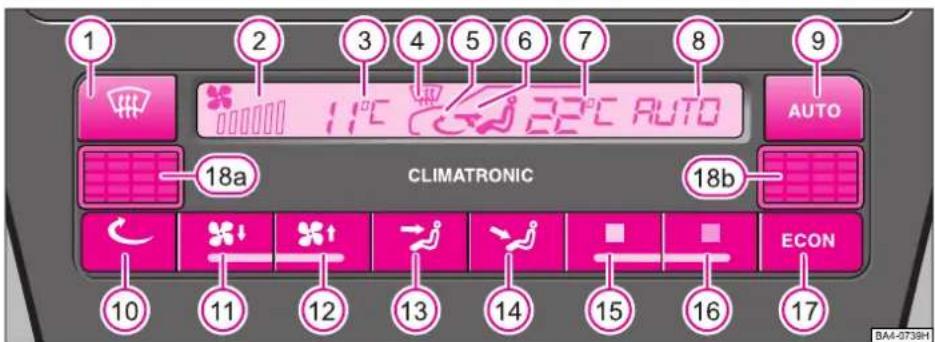
text_image
1 2 3 4 5 6 7 8 9 AUTO CLIMATRONIC 18a 18b ECON 10 11 12 13 14 15 16 17 BA4-0738HPushbuttons
9 - Automatic mode
10 - Recirculated air mode
11 - Pushbutton for „Blower slower“ and for entire system „OFF“
12 - Pushbutton for „Blower faster“ and for switching on entire system
13 - Pushbutton for „Air flow to head“
14 - Pushbutton for „Air flow into footwell“
15 - Reducing interior temperature
16 - Increasing interior temperature
17 - Pushbutton „ECON“ (cooling system off)
Interior temperature sensor
18- Interior temperature sensor (18a - on vehicles with left steering, 18b - on vehicles with right steering)
CONTROLS AND EQUIPMENT
After the appropriate pushbuttons have been pressed, displays 2, 7 and 8 change or displays 4, 5 and 6 appear, respectively.
The automatic control of the system can be influenced with all of the Climatronic pushbuttons.
Recommended standard setting for all seasons of the year:
Temperature approx. 22 °C (72 °F), set pushbutton AUTO mode, vents 3 and 4 so that the air flows to the top.
This setting ensures that a comfortable climate is achieved as rapidly as possible in the car.
That is why this setting should only be altered if you so wish for your own personal well-being.
Arrangement of air vents - refer to page 83.
Operating the Climatronic system
After the ignition is switched on, the system operates in the automatic mode. The positions 2, 3, 7 and 8 then appear in the display panel.
The Climatronic maintains the selected interior temperature in the car fully automatically.
This is done by automatically changing the temperature of the air flowing out of the vents as well as the blower speed (air quantity) and the air distribution.
The system also allows for strong sunlight. It is therefore not necessary to adjust the heating manually.
If a variation is made to the automatic mode before switching off the ignition, the selected functions remain stored permanently. Only the „recirculated air mode“ function is cancelled 20 minutes after the ignition is switched off.
Switching over from degrees Celsius to degrees Fahrenheit and vice versa
First of all, press and hold pushbutton 17 and then operate pushbutton 9.
The appropriate unit of measure for the temperature appears in the display.
Notes on automatic mode (AUTO)
The interior temperature can be selected as desired with pushbuttons 15 and 16. The temperature remains stored until another temperature is selected.
The interior temperature can be set between +18 °C (64 °F) and +29 °C (86 °F). The system automatically controls the temperature within this range.
If a temperature below 18 °C (64 °F) is selected, „LO“ appears in the display. If a temperature higher than 29 °C (86 °F) is selected, „HI“ appears in the display.
In both of these end positions the system operates with maximum cooling or heating capacity, respectively. In such cases, the temperature is not controlled.
It may be in certain operating conditions that the system temporarily carries out functions which are not necessarily expected. For example, after starting the engine when cold, air may be directed primarily into the footwell for a few seconds. This is intentional so that any moist air which is still in the system does not cause the windscreen to mist up.
If the windscreen mists up, first of all press the pushbutton 9 and then the pushbutton 1. After the windscreen is free of mist, press again pushbutton 9.
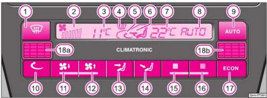
text_image
1 2 3 4 5 6 7 8 9 AUTO CLIMATRONIC 18a 18b ECON 10 11 12 13 14 15 16 17 BA4-0739HVariation from automatic mode
The automatic mode offers the ideal requirements for the well-being of the occupants of the car throughout all the seasons of the year in practically all cases.
In individual situations, however, it may be necessary to vary certain subfunctions of the automatic mode by pressing individual pushbuttons. In this case, the Climatronic continues to operate automatically as before:
■The blower speed and thus the air quantity can be increased or reduced by pressing pushbuttons 11 and 12. This is indicated by an increase or reduction in the number of dashes in position 2.
■ When pushbutton 1 is pressed
- the ECON mode is switched off,
- the windshield and side windows can be defrosted or kept clear (direct vents 4 to the side windows),
- the dehumidifying and defrosting effect on the windshield can be intensified.
Note
To achieve intensive demisting of the windscreen, press button 1, set the blower to maximum speed (button 12) and increase the temperature by pressing button 16 until the display "HI" appears. The air vents for upper and lower body must be closed (button 13 and 14). The air vents 3 must be closed - refer to p. 103. The recirculated air mode must be switched off - button 10.
■ The recirculated air mode is switched on and off by pressing button 10. The symbol 5 appears in the display.
The recirculated air mode prevents polluted ambient air from entering the interior of the car, for example when driving through a tunnel or in congested traffic.
The recirculated air mode can also be selected in order to warm up or cool down the vehicle particularly rapidly. In this operating state, the air is drawn out of the interior of the car and is heated or cooled, respectively.
Warning
The recirculated air mode must only be used for short periods as no fresh air is supplied to the interior and the windows may mist up.
CONTROLS AND EQUIPMENT
It is recommended not to smoke inside the car when using the recirculated air mode as the smoke which is drawn out of the interior settles on the evaporator of the Climatronic system. This produces a permanent odour problem when the Climatronic system is operated, which can only be eliminated by replacing the evaporator.
■The air flow can be directed to the head or into the footwell by pressing the push-buttons 13 and 14.
The air distribution buttons 1, 13 and 14 can also be pressed in combination.
The cooling system is switched off with pushbutton 17 (ECON). In this operating mode, the heating system is controlled automatically (without dehumidification and cooling effect) and the desired interior temperature is reached as rapidly as possible and maintained at a constant level.
The ECON mode is switched off by pressing pushbutton 1. It is sufficient to once again press pushbutton 17 to switch on the ECON mode again.
Please note that in the ECON mode the desired interior temperature cannot be any lower than the ambient temperature.
■You can set the interior temperature with pushbuttons 15 and 16.
The combination of ECON mode and recirculated air is only possible if first of all pushbutton 10 is pressed in the ECON mode and then the ECON button 17.
The ECON mode is switched off by pressing pushbuttons 1, 9 or 10.
■You can switch off the entire Climatronic system (heating, cooling, ventilation) with pushbutton 11. To do this, press and hold pushbutton 11 until the first blower stage appears in position 2. Once again press pushbutton 11 to switch off the system. Only „OFF“ appears in the entire display 3.
Use this function only in exceptional cases, e.g. if there is a fault in the system. It is not normally necessary to switch off the entire system.
Note
Once you no longer require the special functions, switch on the automatic mode again right away by pressing pushbutton 9 (AUTO).

text_image
A B C 1 1 1 1 1 2 2 3 3 4 4 5 5 5 5 BA4-0735HAir vents
Heated or unheated fresh air flows out of all the vents after the appropriate push-buttons are pressed.
The vents are controlled with pushbuttons 1, 13 and 14.
The vents 3 and 4 can also be closed and opened individually with the vertical thumb-wheel:
Vent closed - vertical thumbwheel of air outlet vent in position A and C
Vent open fully - vertical thumbwheel of air outlet vent in position B.
It is also possible to alter the direction of the air flow with the horizontal and vertical thumbwheels of the air outlet vents 3 and 4.
The vertical air flow is regulated by the position of the side knurled wheel.
The horizontal air flow is regulated by the knurled wheel below the air vent grille.
The rear footwell vents are controlled together with vents 5.
Warning
■Clear visibility is an essential element of road safety. It is only assured if all the windows of the car are free of ice, snow and misting.
For this reason, please familiarize yourself with the correct operation of the heating and ventilation system, dehumidifying and defrosting the windows as well as with the cooling mode.
■Maximum heating capacity and rapid demisting of the windows can only be achieved once the engine has reached its normal operating temperature.
CONTROLS AND EQUIPMENT
General notes
■It is important to ensure that the sensor between the defroster vents for the windshield in the middle of the instrument panel and the air grille (item 18 - refer to page 79) is not covered over.
■The air inlet in front of the windshield must be free of ice, snow and leaves to enable the Climatronic to operate properly.
■The heating efficiency depends on the temperature of the coolant - full heating capacity is therefore only available once the engine has reached its normal operating temperature.
■If the AUTO mode has not been switched on for a lengthy period, odours may be caused as a result of environmentally-related deposits on the evaporator.
In order to avoid such odour problems, the cooling system should be switched on at least once a month at the highest blower speed - also during the cool season of the year. At the same time, open a window for a short time.
■At high outside temperatures and high air humidity condensation may drip from the evaporator and form a puddle of water below the vehicle. This is quite normal and not an indication of a leak.
■The blower should always be switched on at a low setting when driving at low speeds in order to prevent the windows misting up. Select the ECON or AUTO mode in this case.
■If the air conditioning system has not been switched on for a lengthy period, odours may be produced at the evaporator because of deposits. Switch on the air conditioning system at least once a month, also during the cold season of the year, to the maximum blower speed in order to remove such odours. At the same time open a window.
Economic use of the Climatronic system
In the cooling mode the compressor of the Climatronic system draws power from the engine and thus influences the fuel consumption. Pay attention to the following points in order to minimize the operating time of the system.
If the interior of the vehicle has been warmed up considerably by the sun's rays when the car is parked, it is recommended to briefly open the windows or doors to allow the warm air to escape.
■The Climatronic should not be switched on when driving if the windows or the sliding roof* are open.
■Select the ECON mode if it is possible to also achieve the desired interior temperature without operating the cooling system.
Operating problems
■If all the symbols in the Climatronic display panel flash for about 15 seconds when the system is switched on, there is a fault in the system. Contact a Škoda dealer.
■If the cooling system does not operate at any time, either:
- the outside temperature may be lower than +5 °C,
- the compressor of the Climatronic may have been temporarily switched off because the engine coolant temperature is too high,
- the fuse may be faulty.
Check the fuse and replace if necessary - refer to page 168 (item 16) of the Owner's Manual. If the problem is not the result of a faulty fuse, switch off the Climatronic system and have it tested.
■If there is a drop in the cooling capacity, switch off the Climatronic system and have it tested.
Electric sliding/tilting roof\*

text_image
B C D A BA4-0711HThe sliding/tilting roof is opened and closed by operating a rotary switch when the ignition is switched on.
After switching off the ignition, it is still possible to open or close the sliding/tilting roof for a further 10 minutes or so, provided a front door has not been opened.
Any desired intermediate position can be selected within the range between D to C (see the dots on the switch and in the illustration).
A - Closing roof
The closing mechanism is equipped with a power limiter. If a resistance is felt when closing the roof, the closing operation is interrupted and the roof is opened again.
The roof can also be fully closed by over-riding the power limiter. With the switch in position A, press at the front or rear on the edge of the handle until the roof is closed.
B - Sliding open fully
(spring-tensioned position)
C - Optimal position
Only minimal wind noises occur in this position.
D - Tilting roof
Note
■When the roof is opened, the sliding panel which acts as a screen against intensive sun's rays, is automatically also opened. It can be pushed closed by hand when the roof is closed.
■If the roof is tilted open in winter, it is necessary to remove any ice crust (otherwise there is a risk of damage to the operating mechanism).
■If the battery is re-connected, it is possible that the tilting/sliding roof does not close fully.
In this case, you must press the rotary switch into position A for about 10 seconds.
CONTROLS AND EQUIPMENT
Convenience system
When the car is locked, the roof can be closed as follows:
■Turn key into lock position (driver or passenger door) and hold until the roof is closed. The closing operation is immediately interrupted if the key is released.
Warning
Close the sliding/tilting roof with care! Closing the roof inattentively can result in injuries.
Do not leave the ignition key in the ignition lock when getting out of the car.
The rollback protection is not active if the convenience system is used. Refer to p. 16 for more detailed information.

natural_image
Diagram of a car interior showing pink plastic components and wiring (no text or labels)Emergency operation
If the system is faulty, the sliding/tilting roof can be closed manually:
■Use a screwdriver to carefully remove the plastic cover.
■Take crank handle out of its fixture, insert fully into the opening and close or open sliding/tilting roof.
■Insert crank handle into its fixture again and fit on the plastic cover.
Sun visors

natural_image
Interior view of a car showing a pink interior panel with a door and seat, no text or symbols visible.The large sun visors can be taken out of the side fixtures and swivelled toward the doors. The small sun visor above the interior rear-view mirror* can only be folded down.
Sun visors with vanity lighting\*
The lighting of the vanity mirror comes on automatically when the sun visor is folded down.
CONTROLS AND EQUIPMENT
Storage compartment on the front passenger side

natural_image
Close-up of a car's front panel showing a pink directional arrow icon (no text or symbols)To open the lid, raise handle and pull lid open.
An additional key is provided with the car for a lockable stowage compartment*.
Warning
For safety reasons, the lid of the stowage compartment should always remain closed when driving.
Beverage holder\*
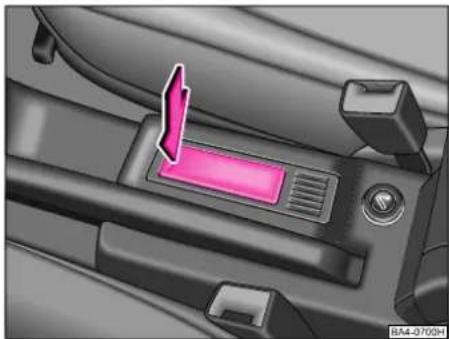
natural_image
Interior view of a car dashboard with a pink indicator button and control panel (no text or symbols visible)The beverage holder moves out and opens after it is pressed in the direction of the arrow.
It is intended for holding beverage cans or cups with a capacity of 0.33 ltr or 0.5 ltr.
Interior lights

text_image
B A B BA4-0509HInterior light (A)
Door contact switching mechanism (on the front and rear door*)
■ Press the switch A to the right into position ☐.
■ On the version without reading lights press the switch A into the middle position.
Switching the interior light on
■ Press the switch A to the left into position ☐.
Switching the interior light on
■ Press the switch A into the middle position O.
■On the version without reading lights press the switch A to the right, the symbol O appears.
CONTROLS AND EQUIPMENT
Note
Interior lights with off time delay* remain on for a few seconds after the doors are closed.
On models fitted with central locking, the interior light remains on for about 20 seconds when the car is unlocked, a door is opened or the ignition key is removed provided the switch is in the door contact position.
On an open door, the interior light is switched off after 60 minutes, in order to avoid discharging the battery.
Reading light (B)\*
Press the switch B, in order to switch the reading light on or off - see illustration on page 87.
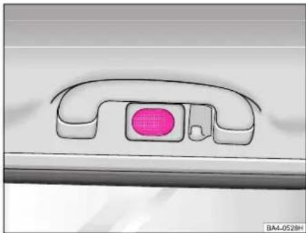
natural_image
Diagram of a car door handle with a pink circular component on the side (no text or symbols)Interior light (rear)\*
The interior light is switched on and off by pressing on the recess in the lens.

natural_image
Close-up of a car door panel with a pink button labeled 'B' and an arrow pointing to it (no text or symbols on the main subject)Front door warning light\*
The light always comes on when the front door is opened.
Note
■If the door is left open for a lengthy time, this can cause the battery to discharge.
■On certain models, a reflector is fitted in place of the door light.
On an open door, the interior light is switched off after 60 minutes, in order to avoid discharging the battery
Luggage compartment light\*
The light is located in the upper left of the luggage compartment (right - Estate)
The light comes on automatically when opening the tailgate of the luggage compartment. If the tailgate of the luggage compartment remains open for longer than 30 minutes, the luggage compartment light will automatically switch off.
Cigarette lighter, socket

natural_image
Mechanical seatbelt assembly with a pink circular component on the side (no text or symbols visible)The cigarette lighter is switched on by pushing in the insert. Once the heating coil is glowing, the lighter insert jumps forward. Remove lighter immediately and use.
Warning
Caution when using cigarette lighter. Careless or uncontrolled use of the cigarette lighter can cause burns.
The 12-volt socket or the socket of the cigarette lighter can also be used for other electrical accessories with a power consumption of up to 180 watts. If the engine is not running, however, the battery is discharged.
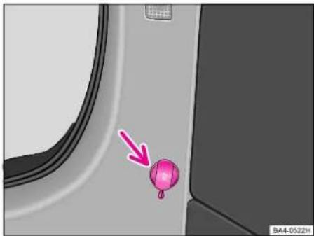
natural_image
Interior view of a vehicle showing a pink balloon attached to the side of a door, with no visible text or symbols.Luggage compartment socket (Estate)
The socket is located in the left of the luggage compartment.
It complies with the DIN-ISO Standard 4165 and must only be used for connecting approved electrical accessories with a power consumption up to 240 watts. If the engine is switched off when the socket is used, the battery will be drained.
For further information, see chapter entitled "Accessories" on page 159.
CONTROLS AND EQUIPMENT
Ashtrays
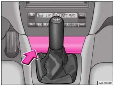
natural_image
Interior view of a car gear shift lever with pink control panel and directional arrows (no text or symbols)Front ashtray\*
The ashtray is located below the fold-open lid. It is opened by pressing on the bottom part of the lid.
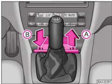
text_image
BA4-0535H A BRemoving
Pull out ashtray in direction of arrow A.
Inserting
Insert ashtray straight into the guide and press lightly in direction of arrow B.
The lid is closed by pressing lightly on the bottom edge.
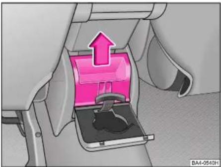
natural_image
Interior view of a car seatbelt with a pink upward arrow indicating direction (no text or symbols)Rear ashtray\*
Removing
Open lid to the rear and pull out ashtray in direction of arrow.
Inserting
Insert ashtray vertically and press it down until it locks in place. Close lid.
A cup holder is provided on the inside of the lid of the ashtray.
Warning
Never place flammable objects in the ashtray - risk of fire!
CONTROLS AND EQUIPMENT
Note holder\*

natural_image
Mechanical gear shift lever with pink plastic clip and arrow indicating action (no text or symbols)■The spectacles case is opened and closed by pressing on the case - see arrow.
■Insert only spectacles of a matching size.
■To remove, open the storage compartment as far as the vertical position, pull up and take off.
Installation is performed in the reverse order.
Note holder Roof rack\*
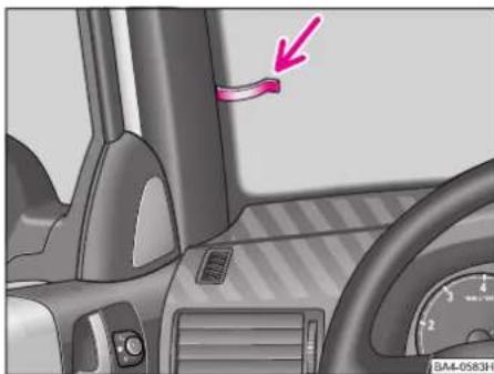
natural_image
Interior view of a car dashboard and steering wheel, showing no visible text or symbolsThe note holder is designed for attaching a car park ticket in parking areas where it is necessary to display a valid ticket. The attached ticket should be removed before starting off in order not to restrict the driver's vision.
Pay attention to the following points if transporting a load on the roof:
■A special roof rack system has been developed for the car. You should therefore always use a system approved by the manufacturer.
■These cross bars are the basis for a complete Škoda roof rack system. For safety reasons, separate additional fixtures are required in each case for transporting luggage, bikes, surfboards, skis and boats.
■The components of this system are available from Škoda Dealers.
■The roof bar is attached to the roof of the car using special attachment parts which are located below the roof trim.
CONTROLS AND EQUIPMENT
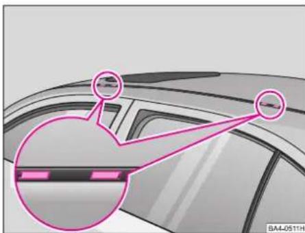
natural_image
Diagram of a car interior with two highlighted circular components and a magnified inset showing the exterior view (no text or symbols)Remove the plastic caps - see illustration - carefully using a thin screwdriver and while doing so do not damage the paintwork.
Position the feet of the roof rack in these openings. Follow the manufacturer's instructions for mounting.
The illustration does not apply for estate models.
If the estate model is not factory-fitted with the railing, it can be obtained from a Škoda Dealer. The Škoda Dealer will also ensure proper mounting.
Any damage to the car which may occur from using other roof rack systems or incorrect fitting are not covered by the warranty.
■Distribute the load evenly. The permissible roof load (including the roof bar system) is 75 kg. Roof load and the permissible gross weight of the vehicle must not be exceeded.
■When transporting heavy or bulky objects on the roof of the car, remember that the handling of the car is altered by the change in the centre of gravity and by the increased wind resistance area. You should therefore adapt your style of driving and speed accordingly.
■Ensure that the opened tailgate does not knock against the roof load.
■On cars fitted with sliding/tilting roof, ensure that the opened roof does not knock against the roof load.
Basic information
Driving the safe way
Passive safety measures reduce the risk of injury in accident situations.
In this section you will find important information, tips and notes on the subject of passive safety in your vehicle.
We have combined everything here which you should be familiar with, for example, regarding seat belts, airbags, child seats and safety of children.
For this reason, please comply in particular with the notes and warnings in this section - for your own interest and in the interest of all those travelling with you.
Warning
■This chapter contains important information on how to use the vehicle for the driver and his occupants. You will find further information on safety, which concerns you and those travelling with you, in the following chapters of this Owner's Manual.
■The complete on-board literature should always be in the vehicle. This applies in particular, if you rent out or sell the vehicle.
Safety equipment
The safety equipment is part of the occupant protection and it can reduce the risk of injuries in accident situations.
Do not put at risk your safety and the safety of those travelling with you.
In the event of an accident, the safety equipment can reduce the risk of injuries.
The following list contains part of the safety equipment in your vehicle:
■Three-point seat belts for all the seats*,
■belt force limiter for front seats*,
■belt tensioner for front seats,
■seat belt height adjuster for front seats,
■front airbags*,
■side airbags*,
■anchoring points for child seats using the „ISOFIX system“,
■head restraints adjustable for height,
■adjustable steering column.
The specified safety equipment works together, in order to optimally protect you and those travelling with you in accident situations.
The safety equipment does not protect you or the people travelling with you, if you or your occupants adopt an incorrect seated position or the equipment is not correctly adjusted or used.
For this reason you will be provided with the information on why this equipment is very important, and how it protects you and the occupants. You will also be informed on what should be observed when using the equipment and how you and the people travelling with you can make full use of the existing safety equipment.
This Owner's Manual contains important warning notes, to which you and those travelling with you should pay attention, in order to reduce a risk of injury.
Safety concerns everybody!
SAFETY
Before setting off
The driver is always fully responsible for his occupants and for the operating safety of the vehicle.
For your own safety and the safety of the people travelling with you, please pay attention to the following points before setting off:
■Ensure that the lighting and the turn signal system are functioning properly.
■Inspect the tyre inflation pressure.
■Ensure that all the windows offer a good visibility to the outside.
■Safely attach the items of luggage - see page 27.
■Ensure that no objects can obstruct the pedal.
■Adjust the mirror, the front seat and the head restraint to match your body size.
■Point out to your occupants that the head restraints must be adjusted to match their body size.
■Protect the children in suitable child seats with correctly fastened seat belts - see page 111.
■Adopt the correct seated position. Also inform your occupants to adopt the correct seated position.
■Fasten the seat belt correctly. Also inform your occupants to properly fasten the seat belts - see page 98.
What influences the driving safety?
The driving safety is primarily determined by the style of driving and the personal behaviour of all the occupants.
The driver is fully responsible for himself and his occupants. If your driving safety is effected, you place yourself and the oncoming traffic at risk. Please refer to the following guidelines.
■Do not get distracted from concentrating on the traffic situation, e.g. by your occupants or mobile phone calls.
■Never drive when your driving ability is impaired, e.g. through medication, alcohol, drugs.
- Keep to the traffic regulations and the permissible speed limit.
■Adjust the driving speed at all times to the road condition as well as to the traffic and weather conditions.
■Take regular breaks on long journeys - at the latest every two hours.
Correct seated position
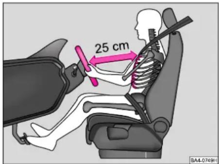
text_image
25 cm SA4-0749HCorrect seated position for the driver Correct seated position for the driver is important for safe and relaxed driving.
For your own safety as well as to reduce the risk of injury in the event of an accident, we recommend the following setting.
■Adjust the steering wheel so that the distance between the steering wheel and your chest is at least 25 cm - see illustration.
■Position the driver seat in the forward/back direction so that you are able to press the pedals with your legs at a slight angle.

natural_image
Illustration of a human skeleton driving a car with steering wheel (no text or symbols)■Adjust the backrest so that you are able to reach the highest point of the steering wheel with your arms at a slight angle.
■Adjust the head restraint so that the top edge of the head restraint is at the same level as the upper part of your head - see illustration.
■Fasten the seat belt correctly - see page 100.
Driver seat adjustment - see page 19.
Warning
■The front seats and the head restraints must always be adjusted to match the body size of the seat occupant. The seat belts must always be correctly fastened in order to provide an optimal protection for you and your occupants.
■ The driver must maintain a distance of at least 25 cm to the steering wheel - see illustration on page 94.
If you do not maintain this minimum distance, the airbag system will not be able to protect you - hazard!
■When driving, hold the steering wheel with both hands firmly on the outer edge in the 9 o'clock and 3 o'clock position.
Never hold the steering wheel firmly in the 12 o'clock position or in another way (e.g. in the middle of the steering wheel or at the inner steering wheel edge).
■When driving, the backrests must not be angled too far back, otherwise this will affect proper operation of the seat belts and of the airbag system - risk of injury!
Correct seated position for the front passenger
The front passenger must maintain a distance of at least 25 cm from the dash panel so that the airbag offers the greatest possible safety when an airbag is deployed.
For the safety of the front passenger and to reduce the risk of injury in the event of an accident, we recommend the following setting:
■Adjust the front passenger seat as far as possible to the rear.
■Adjust the head restraint so that the top edge of the head restraint is at the same level as the upper part of your head - see illustration on page 95.
■Fasten the seat belt correctly - see page 100.
In exceptional cases the front passenger airbag can be deactivated - see page 107.
Front passenger seat adjustment - see page 19.
SAFETY
Warning
■The front seats and the head restraints must always be adjusted to match the body size of the seat occupant. The seat belts must always be correctly fastened in order to provide an optimal protection for you and your occupants.
■The front passenger must maintain a distance of at least 25 cm from the dash panel so that the airbag offers the greatest possible safety when an airbag is deployed.
■Always keep your feet in the foot-well when the car is being driven - never put your feet on the instrument panel, out of the window or on the surfaces of the seats! If it is necessary to apply the brake, or in the event of an accident, you will be exposed to an increased risk of injury!
■When driving, the backrests must not be angled too far back, otherwise this will affect proper operation of the seat belts and of the airbag system - risk of injury!
Correct seated position for the occupants on the rear seats
Occupants on the rear seats must sit upright, keep the feet in the footwell and must have their seat belts correctly fastened.
To reduce the risk of injury in the event of a sudden braking manoeuvre or an accident, the occupants on the rear seats must observe the following.
■Adjust the head restraint so that the top edge of the head restraint is at the same level as the upper part of your head - see illustration on page 95.
■Fasten the seat belt correctly - see page 100.
■If you are transporting children in the vehicle, please use a suitable child restraint system - see pages 111 - 116.
Warning
■The head restraints must always be adjusted to match the body size, in order to offer an optimal protection for you and your occupants.
■Always keep your feet in the foot-well when the car is being driven - never put your feet out of the window or on the surfaces of the seats. If it is necessary to apply the brake, or in the event of an accident, you will be exposed to an increased risk of injury. If an airbag is deployed, you may suffer fatal injuries when adopting an incorrect seated position!
■If the occupants on the rear seats are not sitting upright, the risk of injury is increased due to incorrect routing of the seat belt.
Examples of an incorrect seated position
An incorrect seated position can lead to severe injuries or death for the occupants.
Seat belts offer their optimum protection only if the seat belts are properly routed
Incorrect seated positions considerably reduce the protective functions of the seat belts and therefore increase the risk of injury due to an incorrect routing of the seat belt.
The driver is fully responsible for himself and his occupants, in particular for the children. Do not permit an occupant to adopt an incorrect seated position when the car is moving.
The following list contains the examples of seated positions, which are dangerous for the occupants.
This list is not complete, however we would like you to get interested in this subject.
While the car is moving never:
■stand up in the car,
■stand up on the seats,
■kneel onto the seats,
■tilt the backrest fully to the back,
■lean against the dash panel,
■lie on the rear seats,
■sit to the side,
■lean out of the window,
■put the feet out of the window,
■put the feet on the dash panel,
■put the feet on the seat upholstery,
■occupy the footwell,
■have the seat belt not fastened,
■occupy the luggage compartment.
Warning
■If the occupant adopts an incorrect seated position, he is exposed to life-threatening injuries, in case he is hit by a deployed airbag.
■Before setting off, please adopt the correct seated position and do not change this seated position while the car is moving.
Before setting off, please adopt the correct seated position and do not change this seated position while the car is moving.
SAFETY
Seat belts
Why seat belts?
It has been clearly demonstrated that seat belts offer good protection in the event of an accident. That is why the use of seat belts is a legal requirement in most countries.
Warning
■Fasten your seat belts each time before setting off - even when driving in town! This also applies to passengers in the rear.
■Expectant mothers should also wear a seat belt at all times.
■Apart from their normal protective function, the seat belts are also designed to hold the driver and front passenger in position in the event of an accident to allow the airbag to offer maximum protection.
Transporting children safely - see page 111 - 116.
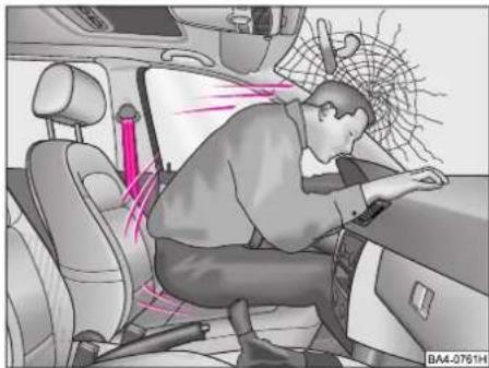
natural_image
Interior view of a car showing a person adjusting the dashboard with visible exhaust lines and seatbelt (no text or symbols)In the event of a frontal collision, car occupants who are not wearing a seat belt are thrown forward and strike parts of the interior of the car, such as the steering wheel, instrument panel, windscreen, in an uncontrolled way.
The widespread opinion that you can support your body with your hands in a minor collision, is incorrect. The forces to which the body is subjected even in accidents which occur at low speed, can no longer be properly absorbed.
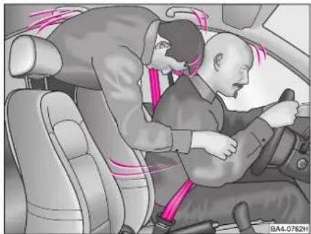
natural_image
Illustration of a car driver assisting a passenger with a pink seatbelt (no text or symbols)It is also important that occupants of the rear seat wear their seat belts otherwise they will be thrown through the car in an uncontrolled way in an accident. A passenger at the rear who is not wearing a seat belt is therefore a risk not only for himself, but also for the front seat occupants.
General notes
■The webbing of the seat belt must not be jammed or twisted and must not chafe against sharp edges.
■On no account should two persons (also not children) use the same seat belt.
■The maximum protection offered by the seat belts is only achieved if you are correctly seated - see page 19.
■The webbing of the seat belt must not run across fixed or fragile objects (spectacles, fountain-pens etc.) because this could cause physical injuries.
■Bulky, loose-fitting clothing (e.g. a winter coat worn over a jacket) adversely affects the correct seated position and proper operation of the belts.
■ It is prohibited to use clamps or similar objects to fix or set the position of a seat belt to match the body's proportions.
■The lock tongue must only be inserted into the seat belt buckle of the appropriate seat - otherwise the seat belt cannot provide the necessary protection and the risk of injury increases.
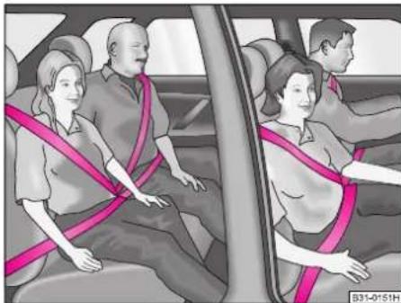
natural_image
Illustration of a family of people seated in a car, each wearing a pink seatbelt (no text or symbols visible)■The webbing of the seat belt should be kept clean. Proper operation of the inertia reel can be affected by dirt (see also the section headed „Care of car“).
■The slot for inserting the lock tongue must not be blocked by paper or such like otherwise the lock tongue may not properly lock in place.
■Seat belts which have suffered damage or have been subjected to excessive stress during an accident and have therefore stretched, have to be replaced - this is best done by a Škoda Dealer. In addition, the anchorage points of the seat belts should be inspected.
■The operation of seat belts fitted to cars in certain export countries may differ from the inertia-reel and lap belts described on the pages which follow.
Three-point inertia-reel seat belts
Inertia-reel seat belts provide full freedom of movement for the occupants if they are unreeled slowly.
The belts block, however, during a sudden brake application.
The inertia reel also blocks the seat belts when the car is accelerated, when driving downhill and when cornering.
The backrests of the front seats must not be tilted too far back otherwise the seat belts may not provide maximum protection.
SAFETY
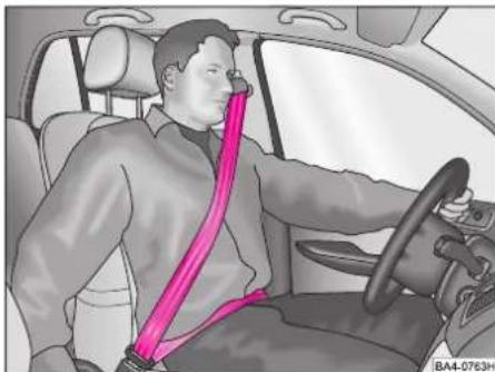
natural_image
Interior view of a car showing a person seated with a pink safety belt, no text or symbols visibleFastening a three-point seat belt
Pull the tongue slowly and smoothly across the chest and hips and push it into the lock part fitted to the seat until the tongue engages audibly (pull to check).
The shoulder part of the belt should run approximately across the centre of the shoulder as shown - on no account against the neck - and be firmly in contact with the body.
The lap part of the belt should always fit tightly across the pelvis. If necessary, pull the belt tight.
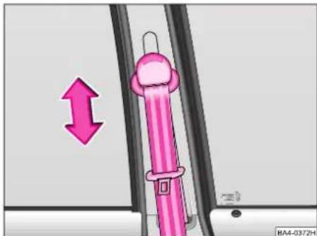
natural_image
Illustration of a pink car seatbelt buckle with a directional arrow indicating left motion (no text or symbols)Adjusting seat belt height
The routing of the front seat shoulder belts can be set to fit the body properly with the aid of the belt height adjuster.
■To adjust, push button with relay fitting up or down so that the shoulder part of belt runs approximately across the centre of the shoulder as shown in the left-hand illustration - on no account against the neck.
■After adjusting, pull the belt with a jerk to ensure that the relay fitting is properly engaged.
The height can also be corrected with the seat adjustment - see page 19.

natural_image
Interior view of a car showing a person seated at the wheel wearing a pink seatbelt (no text or symbols visible)Pregnant mothers should always wear a seat belt.
In this case, the lap part of the belt should be as low across the pelvis as possible so that no pressure is exerted on the abdomen.
A seat belt, which is fitted too loosely, can cause injuries.
Unfastening three-point seat belt
The belt is released by applying pressure with your finger to the red button in the lock. The lock tongue jumps out of the lock when this is done as a result of the spring pressure.
Pass the tongue toward the door by hand so that the retractor can roll the belt up properly. A plastic knob in the belt holds the tongue in a convenient position.
Three-point seat belt with the Inter-lock system\*
On certain models, a three-point seat belt with the Interlock system is used in place of the lap belt.
If the rear seat backrest is not properly locked, the inertia reel blocks the belt which can then not unreel.
Child safety lock for rear centre three-point seat belt
The rear centre three-point seat belt can be blocked (so-called child safety lock) for attaching a child seat.
Switching on child safety lock
■Attach the child safety seat with the three-point seat belt as stated in the instructions of the manufacturer.
■Wind up the shoulder part of the belt fully. A characteristic “clicking” is typical for the unwinding
■After the belt has been locked in the seat belt buckle, allow it to wind up loosely. The child safety lock is now active. It is now no longer possible to unwind the belt. Pull on the seat belt to check that the child safety lock is active.
Switching off child safety lock
The seat belt is unlocked by pushing the button and can then wind up. After being wound up completely, the belt webbing can be unreeled again freely.
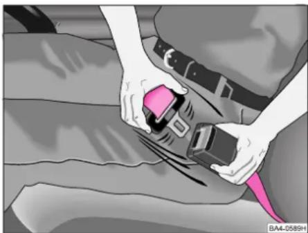
natural_image
Illustration of a person adjusting a car seatbelt, no text or symbols presentLap belt\*
The centre place on the rear seat is fitted with a two-point lap belt.
The lock part of the two-point lap belt is operated in the same way as on the three-point inertia reel belts.
If the lap belt is not in use, it should be fitted to the lock for safety reasons
SAFETY
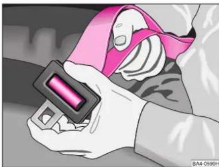
natural_image
Close-up of a hand wearing a pink and white seatbelt with a black button, holding a small object (no visible text or symbols)The lap belt should always fit tightly across the pelvis. If necessary, pull the belt tight.
To lengthen belt, hold the tongue at right angles to belt webbing and pull belt webbing through to the required length - see illustration.
The belt is easier to adjust if tongue and cap are pressed together in the longitudinal direction.

natural_image
Illustration of a hand adjusting a pink belt buckle on a gray fabric (no text or symbols)To shorten belt, it is only necessary to pull the free end of the belt.
The surplus belt length is taken up by moving the plastic slide.
Seat belt tensioner\*
Safety for the belted driver and front passenger is enhanced by the belt tensioners at the inertia reels of the front three-point seat belts.
The system is activated by sensors in the event of a frontal collision of considerable severity. A powder charge is ignited when the seat belt tensioners are activated. This causes the inertia reels to be rotated in the opposite direction of unreeling so that the seat belts are tensioned.
The belt tensioners are not activated in minor frontal collisions, in side or rear-end impacts, in a rollover or in accidents where there is no significant impact to the front of the car.
Warning
The operating life of the seat belts and belt tensioners is 15 years from the date of manufacture of the vehicle. After this time the seat belts and seat belt tensioners have to be renewed in a Škoda Dealership.
Warning
■ Any work on the belt tightener system or within the immediate area, including removal and installation of system components because of other repair work, must only be carried out by a Škoda dealer.
■The protection provided by the system is adequate only for one accident. If the belt tensioners have been activated, the entire system has to be replaced.
■If the car is sold, the buyer should be provided with the complete vehicle wallet.
Notes
■Smoke is released when the belt tensioners are activated. This smoke does not indicate a fire in the car.
■If the car or individual components of the system are scrapped, it is essential to pay attention to the relevant safety regulations. Škoda Dealers are acquainted with these regulations and can provide you with more detailed information in this connection.
Airbag system\*
Front airbag
The front airbag system is only operational after switching on the ignition.
Models with airbag system for driver and passenger are recognizable from the „AIRBAG“ inscriptions on the padded boss of the steering wheel and on the passenger side of the instrument panel.
In addition to the three-point seat belts with belt tensioners, the Airbag System offers further protection for the driver's and passenger's head and chest in a serious frontal collision.
Apart from its normal protective function, the seat belt also has the task of keeping the driver or passenger in such a position so that the airbag can offer maximum protection in the case of a frontal collision.
For this reason, the seat belts should always be used not only because this is required by law, but also for safety reasons! The Airbag System is not activated in the event of:
■side collisions
■rear collisions
■rolling-over
■minor frontal collisions.
The system essentially consists of:
■the electronic control and monitoring unit (control unit),
■one or two airbags (airbag with gas generator) for the:
- driver (in steering wheel),
- front passenger (in instrument panel)
■a warning lamp in the instrument panel - see page 56.
■a warning light in the interior lighting of the car (front)* - see page 108.
■Switch for front passenger airbags* - see page 107.
The operational readiness of the airbag system is monitored electronically.
The airbag warning lamp comes on for a few seconds (self-diagnosis) each time the ignition is switched on.
Note
The airbag system does not require any maintenance over its entire operating period.
SAFETY
A fault exists in the system if
■the warning lamp does not come when the ignition is switched on,
■the warning lamp does not go out a few seconds after switching on the ignition,
■the warning lamp goes out and comes on again after switching on the ignition,
■the warning lamp comes on or flickers during the journey.
Warning
A grey white, non-harmful gas, which is released when the airbag is inflated. This is perfectly normal and is not an indication of a fire in the vehicle.
In the event of an accident in which the airbags are deployed:
■The interior lighting comes on (if the switch for the interior light is in the door contact position).
■The hazard warning light is switched on.
■All the doors are unlocked.

natural_image
Top-down diagram of a car with a pink triangular reflector, no text or symbols presentFunction of front airbag
The airbag system is so designed that it will be deployed during a serious frontal collision. The effective area of the system is shown in the illustration.
If the system is deployed, the airbags fill with propellant gas and inflate in front of the driver and front passenger.
The airbag is inflated in a split second and at a high speed in order to offer the additional protection in the event of an accident. The forward movement of the front seat occupants is cushioned as they plunge into the fully inflated airbag (see right-hand illustration), and the risk of injury to head and upper body is reduced.

natural_image
Interior view of a car showing two crash test car crashers inside (no text or symbols visible)Special openings in the airbag allow a controlled exit of gas when subjected to the pressure of the occupants to cushion the head and upper body. After an accident, the airbag rapidly deflates again so that forward vision is again possible.
If a person is incorrectly seated, the considerable forces active when the airbag is deployed may result in an increased risk of injury.
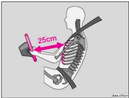
text_image
25cm BA4-0742HWarning
It is therefore important to maintain a distance from the steering wheel or from the instrument panel (min. 15 cm) to enable the occupants to be protected to the maximum possible extent if the system is activated. In addition, the front seats should always be correctly adjusted to the body size of the occupant - see page 19.
■It is not permitted to carry out any modifications to any airbag components as this could result in the airbag being activated.
■The operational life of the front airbag modules is 15 years from the date of manufacture of the car. After this period, it is necessary to have the modules renewed in a Škoda Dealership.
Note
If the car or individual components of the airbag system are scrapped, it is essential to comply with the relevant safety regulations. Skoda Dealers are acquainted with these regulations.
If you do not make use of the seat belts when driving, or if lean forward or adopt an incorrect seated position, you are exposing yourself to an increased risk of injury in the event of an accident.
Warning
The padded panel of the steering wheel and the front passenger area of the instrument panel between the middle and the right-hand vent (surface with inscription „Airbag“) must not have stickers attached, nor should they be covered or modified in any way. These parts should only be cleaned with a dry cloth or a cloth moistened with water.
■No modifications of any kind may be undertaken on the parts of the airbag system. All work on the airbag system, including removing and installing system components during other repair work (e.g. removing steering wheel) should only be carried out by Škoda Dealers.
SAFETY
■Never carry out changes on the front bumper or on the body.
■The protective function of the airbag system only lasts for a single accident. If the airbag has been deployed, the system should be replaced.
■No persons, animals or objects should be located between the front seat occupants and the effective range of the airbags.
■If the vehicle is sold, the complete vehicle wallet should also be passed onto the new owner.
Special features if front passenger airbag is deactivated
As soon as possible activate the airbags, so that the safety of the vehicle is increased.
Your car offers you the technical facility of deactivating the front passenger airbag and also the side airbag.
Deactivating the front airbag and also the side airbag can be carried out by your Škoda Dealer.
On vehicles with the switch, the front passenger airbag and also the front passenger side airbag can be deactivated with this switch in the glove box - see page 107.
Warning
A child seat in which the child faces with its back in the direction of travel, may only be used in the front passenger seat if the front passenger airbag (in certain countries also on child seats in which the child faces the direction of travel) has been deactivated - refer to page 107. Otherwise, there is a risk of the child suffering severe or even fatal injuries if the airbag is deployed. In certain countries, legal requirements necessitate deactivating the side airbag. If a child is nevertheless seated on the front passenger seat, observe the legal requirements for the use of child seats.
As soon as you no longer use the child safety seat, you should reactivate the front passenger airbag.
If using a child seat, please read the section headed „Safety of Children“ on page 111.
The operational readiness of the airbag system is monitored electronically even if the passenger airbag is deactivated.
If the airbag was switched off with a diagnostic unit, the warning light comes on in the dash panel insert for about 3 seconds after the ignition is switched on and then flashes for a further 12 seconds.
If the airbag was deactivated with an Airbag switch* in the glove box, the airbag warning light comes on in the dash panel insert for about 3 seconds and the deactivation of the airbag is signaled if the warning light "AIRBAG " OFF" comes on in the interior light - see page 108.
Switch for front passenger airbags*
You can deactivate the passenger-side front airbag and if the vehicle is equipped with side airbags, also the passenger-side side airbag with the switch
The airbag(s) may be deactivated only if, in exceptional cases, it is necessary to install a child seat on the front passenger seat.
It is preferable to place the child seat always at the rear.
For safety reasons the driver of the car is under the obligation to have the airbag switched on when driving.
Warning
Deactivate the airbag only when the ignition is switched off! Failure to observe this instruction may result in a fault in the airbag system and consequently cause subsequent deployment of the airbag.

text_image
345 BA4-3717HDeactivating airbag
■Switch the ignition off.
■Use the ignition key to turn the airbag switch -arrow- into the "OFF" position. The ignition key must be in the vertical position.
■Check whether the airbag warning light in the interior lighting (front) lights up when the ignition is switched on.
Warning
The driver of the car is responsible for ensuring that the airbag is deactivated or activated.
SAFETY
Switching on airbag
■Switch the ignition off.
■Use the ignition key to turn the airbag switch - arrow - into the „ON“ position. The ignition key must be in the horizontal position.
■Check whether the airbag warning light in the interior lighting (front) goes out when the ignition is switched on.
After activating the airbag and then switching on the ignition, the airbag warning light comes on for about 3 seconds.
Warning
The driver of the car is responsible for ensuring that the airbag is deactivated or activated.

text_image
AIRBAG OFF BA4-0716H„Airbag OFF“ warning light (airbag deactivated)\*
The warning light is located in the front interior lighting of the car.
Each time the ignition is switched on, the warning light comes on in the dash panel for a few seconds (self diagnosis).
The warning light comes on if the passenger-side airbag or also the side airbag has been deactivated.
If the warning light in the instrument panel flashes, there is a fault in the airbag system. Contact a Škoda Dealer immediately to have this rectified
Warning
If the warning light flashes:
■There is a risk of the passenger-side airbag being deployed in the event of an accident. For this reason, do not install a child seat on the front passenger seat.
■If the front passenger seat is occupied, there is a risk of the airbag being deployed unexpectedly and also causing possible injuries to the occupant of the front passenger seat.

natural_image
Interior view of a car showing four seats with seat covers and a logo on the side (no text or symbols on the seats)Side airbag\*
The side airbags are installed in the sides of the backrest upholstery of the driver and front passenger seats. They are identified by the inscriptions „AIRBAG“ in the top half of the backrests - see illustration.
The side airbag system in combination with the three-point seat belts offers additional protection for the upper body of the driver and front passenger in the event of a side collision of considerable severity.
In the event of a side collision, the side airbags reduce the risk of injury to the part of the body of the front occupants facing toward the point of impact.
In addition to the normal protection which they offer, the seat belts are also designed to hold the driver and front passenger in position in the event of a side impact so that the side airbag is able to offer maximum protection.
Warning
The maximum protection offered by the seat belts and the airbag system is only achieved if the occupants are correctly seated - see page 94.
The system consists essentially of
■the electronic control and monitoring unit,
■the side airbags installed in the sides of the backrests of the front seats,
■a warning lamp in the instrument panel - see page 56.
Please refer to page 56 for information on the operational readiness and possible faults in the system.
The side airbag system is not activated in the event of:
■frontal collision
■minor side collision
■rear collision
■ rollover.
The airbag system is not a substitute for the seat belt but is part of the entire passive vehicle safety concept. Please note that the airbag system is only able to offer optimal protection in combination with fastened seat belts.
That is why, you should always use the seat belts not only because this is a legal requirement, but also for safety reasons!
Please refer to the information on pages 98 to 103 in this connection.
Note
The airbag system is maintenance-free throughout its entire operating life.
SAFETY
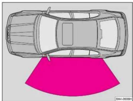
natural_image
Top-down line drawing of a car with a pink curved surface (no text or symbols)When are the side airbags deployed?
In the event of a major side collision, the side airbag on the side of vehicle impact is deployed.
The effective range of the side airbag system is shown in the illustration.
It is possible, in certain accident situations, that both the front as well as the side airbags are deployed.

natural_image
Interior view of a car showing a person seated in the seat with a pink seatbelt (no text or symbols visible)Operating principle
If the system is activated, the airbags fill with propellant gas.
The airbag is inflated in a split second at a high speed in order to offer additional protection in the event of an accident.
When the airbag is fully inflated, the movement of the occupant is cushioned and the risk of injury to the upper body on the side of the impact is reduced.
The specially developed airbags allow the propellant gas to exit in a controlled flow under the weight of the occupant to thus softly cushion head and upper body.
Smoke is produced when the airbag is inflated. This is perfectly normal and is not an indication of a fire in the car.
Safety information
Warning
■To ensure that the side airbags are able to provide their full protection, it is important that the occupants always maintain the seat position set by the seat belts - see page 94 - during the entire journey.
■No persons, animals or objects should be located between the front seat occupants and the effective range of the airbags. In addition, no accessory parts, such as drink holders, should be attached to the doors if the car is fitted with side airbags.
Safety of children
■Only light items of clothing should be hung up on the clothes hooks in the car. No heavy or sharp-edged objects should be stowed in the pockets of the items of clothing.
■Avoid any excessive force acting on the side panels of the seats, such as a sudden knock, or pressing with your foot etc., otherwise the system may be damaged. In this case, the side airbags would not deploy!
■On no account may seat or protective covers be fitted over the driver or front passenger seats fitted with side airbags. As the airbag inflates out of the backrest of the seat, the protective function offered by the side airbags would be restricted if seat protective covers were used.
■If the original seat cover or the stitching in the module area of the side airbag is damaged, the seat cover in question should be replaced immediately by a Škoda Dealer.
■The protection offered by the airbag system is sufficient only for one accident. If the airbag has been deployed, the system should be renewed.
■If the occupants lean forward or adopt an incorrect seated position when driving, they are exposing themselves to an increased risk of an injury in the event of an accident.
■A child seat in which the child faces with its back in the direction of travel, may only be used in the front passenger seat if the front passenger airbag (in certain countries also on child seats in which the child faces the direction of travel) has been deactivated - refer to page 107. Otherwise, there is a risk of the child suffering severe or even fatal injuries if the airbag is deployed. In certain countries, legal requirements necessitate deactivating the side airbag. If a child is nevertheless seated on the front passenger seat, observe the legal requirements for the use of child seats.
■The operating life of the airbag module is 15 years from the date of manufacture of the vehicle. After this time, it is necessary to have the modules renewed in a Škoda Dealership.
Accident statistics reveal that children who sit at the rear are generally better protected than when seated on the front passenger seat. Children younger than 12 years should normally travel on the rear seat of the car ^1) . They should be protected by a child restraint system or by the standard car seat belts, depending on age, body size and weight. For safety reasons, the child restraint system should be installed behind the front passenger seat.
Warning
■All vehicle occupants, in particular children, must fasten their seat belt when the car is moving.
■ Never allow your child to stand in the car or to kneel on the seats when the car is moving. If an accident occurs, your child will be thrown through the car and may suffer fatal injuries.
SAFETY
Warning
If children lean forward when the car is moving or adopt an incorrect seated position, they are exposed to a greater risk of injury in the event of an accident. This is particularly true of children who are transported on the front passenger seat if the airbag system is deployed in the event of an accident. This can result in severe or even fatal injuries.
■Children under 1.50 m (5') tall or younger than 12 years must not use normal seat belts without a child restraint system as this may otherwise result in injuries to the stomach and neck area.

natural_image
Illustration of a woman seated in a car with a baby running away, no text or symbols presentWarning
■On no account should children - even small babies! - travel sitting on an occupant's lap.
■Do not leave your child in a child seat unattended.
■Certain outside climatic conditions can cause life-threatening temperatures in the vehicle.
■When using the seat belt, also refer to the section on „Seat belts“.
Classification of child seats
Only child restraint systems which have an official seal of approval and are suitable for child, may be used.
The Standard ECE-R ^1) 44 applies to child restraint systems and divides these into 5 classes:
Class 0: 0-10 kg
Class 0+: up to 13 kg
Class 1: 9-18 kg
Class 2: 15-25 kg
Class 3: 22-36 kg
Child restraint systems tested in accordance with ECE-R 44 Standard are clearly marked with the ECE-R 44 test symbol (large „E“ in a circle, with test number below) on the seat.
Use of child safety seats
An overview of the usefulness of child seats on each of the seats according to the EG guidelines 77/541:
| Child seat according to group | Front Rear passen-ger seat | Rear on seat the side middle | |
| 0 | U | U+ | U |
| 0+ | U | U+ | U |
| 1 | U | U+ | U |
| 2+3 | U | U | U |
- Universal category - seat is suitable for all approved types of child safety seats.
⊕ - The seat can be fitted with fixing eyes for the „ISOFIX system“.
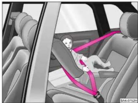
natural_image
Interior view of a car showing a child seated in a seatbelt, with no visible text or symbolsClass 0 / 0+
For babies up to about 9 months weighing up to 10 kg or babies up to about 18 months weighing up to 13 kg, respectively, child seats which can be adjusted into the reclining position are best suited - see illustration.
If the vehicle is equipped with front passenger airbag, in certain cases, such child seats must not be used on the front passenger seat - see page 115.
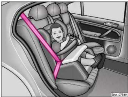
natural_image
Interior view of a car showing a child seated in a car seat with a pink safety belt (no text or symbols visible)Class 1
For babies and small children up to about 4 years weighing between 9 and 18 kg it is recommended to use child seats for the lower weight range in which the child is seated with its back to the direction of travel and for the weight range above class 0+, it is recommended to use child seats in which the child is seated in the direction of travel (see illustration).
If the vehicle is equipped with front passenger airbag, in certain cases, such child seats must not be used on the front passenger seat - see page 115.
SAFETY
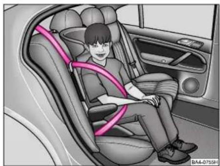
natural_image
Interior view of a car showing a child seated in a car seat with a pink safety belt (no text or symbols visible)Class 2
For children up to about 7 years weighing between 15 and 25 kg it is recommended to use child seats in combination with the three-point seat belts.
Warning
The shoulder belt part must run approximately across the middle of the shoulder - on no account across the neck - and fit snugly against the top part of the body. The lap belt must run across the pelvis - and not across the stomach.
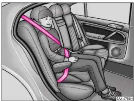
natural_image
Interior view of a car showing a person seated in a seat with a pink safety belt (no text or symbols visible)Class 3
For children of about 7 years weighing between 22 and 36 kg and with a height of less than 1.50 m, it is recommended to use seat cushions in combination with the three-point seat belts.
Warning
The shoulder belt part must run approximately across the middle of the shoulder - on no account across the neck - and fit snugly against the top part of the body. The lap belt must run across the pelvis - and not across the stomach.
Children taller than 1.50 m (5') can use the standard seat belts fitted to the car without a seat cushion.
Notes
■We recommend using child restraint systems from the Genuine Accessories range of Škoda dealers. Such systems have been developed and tested for use in Škoda vehicles, and comply with the ECE-R 44 Standard.
Warning
■Particular care is required if child restraint systems are used which are bolted on together with the belts fitted in the vehicle. The belts must be screwed into the hole over the complete nominal length and tightened to a torque of 40 Nm.
■The seat belts must be inspected to ensure they are correctly routed. In addition, it is important to ensure that the belt webbing cannot be damaged by any sharp-edged fittings.
■Only one child may be belted in using a child restraint system.
■Attention should be paid to legal regulations and the instructions of the relevant manufacturer for the installation and use of child restraint systems.
Use of child seats on front passenger seat
For safety reasons, we recommend installing child restraint systems on the rear seats, whenever possible. If a child seat is nevertheless used on the front passenger seat, it is important to observe the following instruction in connection with the front passenger airbag:
Warning
■A child seat in which the child faces with its back in the direction of travel, may only be used in the front passenger seat if the front passenger airbag (in certain countries also on child seats in which the child faces the direction of travel) has been deactivated - refer to page 107. Otherwise, there is a risk of the child suffering severe or even fatal injuries if the airbag is deployed.

text_image
AirbagBA4-0743H
In certain countries, legal requirements necessitate deactivating the side airbag. If a child is nevertheless seated on the front passenger seat, observe the legal requirements for the use of child seats.
This is also clearly stated on the sticker, which is located on the centre column of the front passenger side. The sticker is visible upon opening the front passenger door. Another warning sticker is located on the windscreen near the front passenger seat.
Warning
■If a child seat is used in which the child is seated in the direction of travel, the front passenger seat must be moved fully back.
Child safety and side airbag\*
In addition to the driver and front passenger airbags your Škoda car may also be equipped with 2 side airbags which offer enhanced protection to the occupants in the event of a side impact.
To ensure that the occupants can benefit from this additional protective function, the side airbag must be inflated in fractions of a second in the event of a collision (refer also to page 109 of the Owner's Manual).
When the airbag is deployed, a considerable force is generated which may result in injuries being caused to occupants by the airbag or by any objects which are within the inflation range of the side airbag if the occupant is not correctly seated.
This applies particularly to children if they are not transported in accordance with legal provisions.
SAFETY
Warning
■To avoid severe injuries, therefore, children must always be transported safely in the vehicle with a restraint system which matches the age, body size and weight of the child.
■Children must never be positioned with their head in the inflation range of the side airbag. Risk of injury!
■Do not place any objects in the inflation range of the side airbag. Risk of injury!
■A child seat in which the child faces with its back in the direction of travel, may only be used in the front passenger seat if the front passenger airbag (in certain countries also on child seats in which the child faces the direction of travel) has been deactivated - refer to page 107. Otherwise, there is a risk of the child suffering severe or even fatal injuries if the airbag is deployed. In certain countries, legal requirements necessitate deactivating the side airbag. If a child is nevertheless seated on the front passenger seat, observe the legal requirements for the use of child seats.
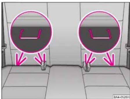
text_image
BA4-052SHAttaching child seats („ISOFIX“ system)
Two eyes for attaching a child seat with the „ISOFIX“ system are provided between backrest and seat cushion at the two outer rear seats.
Child seats with the „ISOFIX“ system can be installed quickly, conveniently and safely. The seat should be installed as specified in the installation instructions enclosed with the „ISOFIX“ child seat. Always ensure that the child seat engages properly when installed (pull as a check!).
Notes
An „ISOFIX“ child seat must only be attached in the vehicle using the „ISOFIX“ system if the child seat bears an official seal of approval for the particular vehicle model in conformity with the ECE-R 44 Standard.
Warning
■Before using an „ISOFIX“ child seat which you have acquired for another vehicle, please check with your Škoda dealer whether your child seat is recommended for the Škoda-Octavia.
■Certain child seats with "ISOFIX" attachment system can also be attached with the usual three-point seat belt. Attention should be paid to the instructions of the child seat manufacturer for the installation and removal.
The first 1500 kilometres (1000 miles) - and after
Running in
During the first few operating hours the internal friction of the engine is higher than later on when all the moving parts have bedded down. How well this running-in process is done depends to a considerable extent on the way the vehicle is driven during the first 1500 km (1000 miles).
Up to 1000 km (600 miles)
the following general rules apply:
■Do not use full throttle
■Do not drive faster than 3/4 of top speed
■Avoid high engine speeds
■Avoid towing a trailer, if possible
Warning
■New tyres should also be „run in“ because they do not have maximum adhesion at the start. This should be taken into account by driving carefully during the first 500 km (300 miles).
■New brake pads have to „bed down“ and do not therefore have their ideal friction force during the first 200 km (120 miles) or so. The slightly reduced braking power can be compensated for by applying greater pressure on the brake pedal. This also applies subsequently after replacing the brake pads.
From 1000 - 1500 km (600 - 1000 miles)
It is possible to gradually increase up to the maximum speed of the gear engaged or to the maximum permissible engine speed, respectively.
During and after the running-in period:
■Do not overrev the engine when cold - either in Neutral when driving. All the speeds and revs stated only apply when the engine is properly warm.
Do not drive at unnecessarily high engine speeds - changing up early helps to save fuel, reduces noise and protects the environment - see also page 118.
■Do not let the engine labour - change down when engine no longer runs smoothly.
After the running-in period
On cars fitted with a rev counter the maximum permissible engine speed is marked by the start of the red range on the scale of the rev counter. The needle of the rev counter must not move into this range.
DRIVING TIPS
Driving economically while protecting the environment
Various factors determine fuel consumption, the impact on the environment and wear-and-tear of the engine, brakes and tyres.
Your personal style of driving
determines to a great extent the economical aspect and the development of exhaust and noise:

Do not warm up engine when the vehicle is stationary.
At idling speed it takes a very long time until the engine becomes operationally warm. However, in the warm-up phase, wear and the discharge of pollutants is particularly high. For this reason, drive off immediately the engine has started and avoid high engine speeds.
The cold engine consumes approx. 15 - 20 litres/100 km of fuel immediately after starting. Fuel consumption drops to 10 litres/100 km after just 1 kilometre. The engine reaches its operating temperature (outside temperature and engine dependent) only after about 4 to 10 kilometres and the fuel consumption then stabilizes. You should therefore avoid driving short distances whenever possible.

Avoid full throttle acceleration.
Accelerating with feeling not only considerably improves fuel economy but also reduces the impact on the environment and wear-and-tear.

Do not drive at unnecessarily high engine revs - change up as soon as sible and only change down when engine no longer runs smoothly.
Fuel consumption, for example, is more than twice as high in 2nd gear than it is in top gear. At the same time, the lower engine speed means a reduction in engine noise.

Try not to drive at maximum speed.
Fuel consumption, exhaust pollution and noise increase disproportionately at high speeds. If you make use of approximately only 3-quarters of top speed, your fuel consumption will be reduced by about half. Experience has shown that the loss in time is only marginal.

Drive as smoothly as possible and look well ahead.
Unnecessary acceleration and braking has to be paid for with higher fuel consumption and a greater impact on the environment.

Switch off the engine when standing in traffic (traffic lights, railway issues etc.).
Individual operating conditions
naturally also affect fuel consumption.
The following factors, for instance, are not favourable to good fuel consumption:
■High traffic density, particularly in large towns with numerous traffic lights.
■Frequent stop/start driving, always re-starting and warming up the engine.
■Driving in heavy, slow moving traffic in low gear so that the engine speed is relatively high in relation to the speed driven.
Obviously, fuel consumption is also affected by factors over which the driver has no control. It is, for example, normal for fuel consumption to increase in the winter or in severe conditions such as poor roads, towing a trailer etc.
The technical prerequisites
for low fuel consumption and efficiency were „built in“ at the factory. Particular importance was placed on the lowest possible effect on the environment. To retain and make the best possible use of these characteristics attention should be paid to the following points:
The prescribed maintenance operations should be carried out exactly as specified in the Service Schedule.
Having your car serviced by a Škoda Dealer at the specified intervals not only ensures that it is always in proper roadworthy condition but that it operates economically, with minimal environmental impact and provides you with many years of motoring.
Check the tyre pressures every 4 weeks.
Low tyre pressures increase the rolling resistance. This not only increases the fuel consumption and tyre wear, but the handling is also impaired.
Do not carry any unnecessary loads in the luggage compartment.
The weight of the car has a major effect on fuel consumption, particularly when driving in towns where you frequently have to accelerate. The rule of thumb which applies is that every 100 kilograms of weight increases fuel consumption by about 1 litre/100 km (1 litre/62 miles).
Do not fit the roof rack unless it is really needed.
Particularly at high speeds the increased air resistance makes itself felt in higher fuel consumption.
Electrical consumers should only be switched on when they are actually required.
Heated rear window, fog lights etc. have a considerable energy demand. The higher alternator load also increases the fuel consumption. For instance, over a period of 10 hours, the heated rear window will increase fuel consumption by approximately 1 litre.
Keep a frequent check on your fuel consumption.
The fuel consumption should be checked each time the tank is filled up. By doing this inconsistencies on the vehicle which lead to increased fuel consumption can be detected sooner.
Check the oil level each time you refuel.
The oil consumption depends to a great extent on the engine load and speed. Depending on the style of driving the consumption can be as much as 0.5 litre/1000 km.
It is normal for the oil consumption of a new engine to reach its lowest level after a certain mileage has been covered. The consumption cannot be properly assessed until the vehicle has run approx. 5000 km.
This also applies to the fuel consumption and the engine output.
DRIVING TIPS
Trouble-free operation of the emission control system is decisive for environmentally friendly operation of the vehicle.
That is why it is important to note the following points:
■Vehicles fitted with a catalytic converter must only be driven on unleaded petrol - see page 128.
■Never drive until the fuel tank is completely empty on vehicles fitted with a catalytic converter. The irregular fuel supply can cause misfiring. This allows unburnt fuel into the exhaust system which can cause overheating and damage to the catalytic converter.
■If misfiring, a loss of power and rough engine running occur when driving, this may be caused by a fault in the ignition system. In this case, uncombusted fuel can get into the exhaust system and thus pass to the atmosphere. In addition, the catalytic converter may be damaged as a result of overheating. Reduce your speed immediately and have the fault rectified at the nearest Skoda Dealer.
■Do not switch off the ignition when driving.
■Do not overfill engine with oil - see page 140.
■Do not tow start vehicle for more than 50 m - see page 179.
Warning
Due to the high temperatures which can occur in catalytic converters in very unfavourable conditions, the vehicle should not be parked in such a way that the catalytic converter can come into contact with inflammable materials.
Note
Even if the emission control system is operating perfectly properly, there may be a sulphurous exhaust smell in certain engine operating conditions. This depends on the sulphur content in the fuel being used.
Quite often this can be remedied by selecting another brand of fuel or filling up with unleaded premium petrol.
Brakes
General notes
■The wear of the brake pads depends to a great extent on the driving conditions and your style of driving. Consequently, it may also be necessary to have the thickness of the brake pads inspected at a Škoda Dealer between the intervals stated in the Service Schedule, particularly if your car is driven frequently in towns or over short distances, or in a very sporty manner.
■Change down in good time when driving downhill, in order to make use of the engine braking effect. This relieves the strain on the brake system. When the brakes are applied, do not keep them on continuously, apply and release the brakes alternately.
■Under certain operating conditions, for example after driving through water, after heavy rain or after washing the vehicle, the braking effect may be retarded by wet, or in winter iced-up brake discs and pads - the brakes must be dried out first by applying the footbrake.
The full braking effect may also be delayed when the car has been driven for some time on heavily salted roads without using the brakes, because the layer of salt on the discs and pads has to be removed first.
Warning
If a front spoiler, full-size wheel trims etc., are retrofitted, it is necessary to ensure that the flow of air to the front brakes is not restricted - otherwise the brakes may overheat.
Brake booster
The braking force boosts the pressure, which you generate with the brake pedal. The necessary pressure is only generated when the engine is running.
Warning
The brake booster only operates when the engine is running.
Never switch off the engine before the vehicle is stationary.
In the case that the brake booster is not operating - e.g. because the vehicle has to be towed or because there is damage to the brake booster - the brake pedal has to be depressed with a significantly greater force, in order to balance out the missing brake boosting effect.
Because if you do not stop as normal, this can cause an accident and severe injuries.
Brake Assist\*
The Brake Assist boosts the brake servo effect during a brake application in a hazardous situation and is able in this way to assist the rapid build-up of brake pressure. In emergency situations the majority of car drivers do apply the brakes in time, but not with the brake pedal force which is necessary for achieving maximum deceleration. Valuable braking distance is lost as a result! The Brake Assist is activated as soon as the brake pedal is depressed very rapidly. A higher brake servo assistance than is usual in normal brake applications, is then available.
Consequently, it is possible to build up within a very short time the brake pressure which is required for achieving maximum deceleration with only a correspondingly slight counterforce on the brake pedal.
Depress the brake pedal further for achieving the shortest possible braking distance. Do not reduce the foot pressure on the pedal! The Brake Assist is able in this way to help you in critical situations by building up the brake pressure more rapidly and shortening the stopping distance. The advantages offered by the ABS are fully exploited by the Brake Assist. As soon as the brake pedal is released, the Brake Assist function is switched off then automatically and the usual service brake function is again available.
Warning
■The Brake Assist is also not in a position to overcome the physical limits which apply to the braking distance.
■This is something you should remember particularly when driving on smooth or wet road surfaces.
■Adapt your style of driving always to the road condition and the traffic situation. The increased safety which the Brake Assist offers you must not lead you to take any safety risk!
DRIVING TIPS
Anti-lock brake system (ABS)\*
The ABS plays a major part in increasing the active safety of the vehicle.
The big advantage when compared with a conventional brake system is that even during a full brake application on a slippery road surface the best possible steerability is retained for the road condition because the wheels do not lock.
However, one must not expect the ABS system to shorten the braking distance under all conditions.
How the ABS system works
An automatic test procedure is carried out once the car has reached a speed of about 20 km/h. A pump noise may be audible for about 1 second during this check.
When the turning speed of a wheel reaches a level which is too low for the vehicle speed and it tends to lock, the brake pressure to this wheel is reduced. The brake pressure is controlled individually for each wheel. This ensures that the braking action is even and that driving stability is retained to the maximum possible extent.
This control process makes itself felt by a pulsing movement of the brake pedal and is accompanied by noises. This is done deliberately as a warning to the driver that a wheel or wheels are in the locking range. The brake pedal should remain depressed to enable the ABS to offer ideal control within this range - on no account pump the brake pedal!
Warning
The ABS system can also not overcome the physical limits. This has to be born in mind, particularly on slippery or wet roads. When the ABS is operating in the control range, your speed should immediately be adapter to road and traffic conditions.
The increased amount of safety available should not tempt you into taking risks.
If a fault occurs in the ABS system, this is indicated by a warning lamp - see page 60.
Warning
If a fault exists, only the normal brake system is operational. You should drive to a Škoda Dealer as soon as possible. Adapt your speed and driving style to the changed circumstances as the extent of the damage to the ABS system is not known.
Electronic differential lock (EDL)\*
Cars fitted with the anti-lock brake system (ABS) ^* can be equipped in addition with an electronic differential lock.
The EDL system makes it much easier or, in deed, at all possible to move off, accelerate and drive uphill even on unfavourable road surfaces.
The EDL operates automatically - in other words without any action on the part of the driver.
It monitors the speed of the driven wheels using the sensors of the ABS system.
If the road surface is slippery on one side, a difference in speed exists between the driven wheels. It is then necessary to produce more throttle, for example, when moving off on a hill, on a slippery road surface etc. The EDL function compensates for the difference in speed by braking the wheel which is slipping and transmits the power through the differential to the other driven wheel.
This control process makes itself noticeable by characteristic noises.
In order to achieve the optimal effect of the EDL system, depress the accelerator pedal and the clutch when starting off to match road conditions.
Warning
When accelerating on a smooth road surface, for example on ice and snow, depress the accelerator carefully.
The driven wheels may slip despite the EDL and thus affect the driving stability of the car.
The EDL is switched off automatically if unusually severe stresses occur. The car can continue to be driven and has the same characteristics as a car without EDL. That is why no indication is provided if the EDL is switched off.
The EDL switches on again automatically as soon as the brake has cooled down.
If the ABS warning lamp comes on, see page 60, there might also be a fault in the EDL. Drive to a Škoda Dealer as soon as possible!
Warning
Your driving style should always be adapted to the condition of the road and the traffic situation. The additional safety offered by the EDL must not tempt you into taking a safety risk!
Engine braking control (EBC)\*
The EBC operates in conjunction with the ABS. It is intended to prevent the driven wheels of the car being excessively sharply braked when „braking with the engine“ as a result of releasing the accelerator or shifting down on a smooth road surface. The EBC automatically increases the engine speed in order to maintain optimal steerability of the car even when „braking with the engine“.
All-wheel drive\*
The four-wheel drive system of your car requires no manual intervention on your part.
The force is distributed to the driven wheels automatically and is optimally matched to the handling of the car and to the particular road conditions.
The four-wheel drive concept is designed for high engine output and provides your car with excellent drivability both in normal road conditions as well as in extreme conditions such as driving on snow and ice.
It is important, however, to pay attention to the following safety information:
DRIVING TIPS
Warning
Your style of driving should always be matched to the condition of the road and the traffic situation. The enhanced safety offered by the four-wheel drive and ABS systems must not tempt you to take any risks regarding your safety!
The braking power of the car is limited by the adhesion of the tyres and is no different than that of a car with front-wheel drive.
You should therefore not be tempted to drive at too high a speed even though the car still provides good acceleration on smooth and slippery road surfaces.
It is particularly important to note on wet road surfaces that the front wheels may aquaplane at high speeds. In contrast to a vehicle fitted only with front-wheel drive, the start of aquaplaning is not indicated by the engine suddenly revving up. For this reason, do not drive at too high a speed, but always match your speed to the road conditions.
Use of winter tyres
Four-wheel drive already offers good vehicle traction in wintry road conditions with the standard tyres. It is nevertheless recommended to fit winter or all-weather tyres to all four wheels in order to improve traction and braking. For further information - refer to page 157.
Use of snow chains
Snow chains must also be fitted to a vehicle with four-wheel drive if the use of snow chains is mandatory. Snow chains must only be fitted to the front wheels. For further information regarding snow chains - refer to page 157.
Towing a trailer
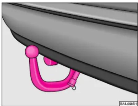
natural_image
Close-up of a car's side panel with a pink handle and circular head (no text or symbols visible)The car is intended mainly for the transportation of persons and luggage, but it can also be used to tow a trailer if the appropriate technical equipment is fitted.
Detachable ball head\*
■Refer to the enclosed instructions for attaching and detaching the ball head.
For further information - refer to p. 157.
Technical requirements
■If the car is supplied with a factory-fitted towing bracket, all that is technically and legally necessary for towing a trailer has already been taken into account.
■If the trailer to be towed has a 7-pin connector, you can obtain an adapter cable from Škoda Dealers.
■Škoda Dealers are acquainted with the details of retrofitting a towing bracket and modifying the cooling system. You should therefore have a towing bracket fitted by a Škoda Dealer.
Operating instructions
■The permissible trailer weights must on no account be exceeded.
■The trailer weights stated are only applicable for altitudes up to 1000 m above mean sea level (MSL). As the engine output and thus the climbing ability drops due to the decreasing air density, the weight of vehicle and trailer must also be reduced by 10 % for each further 1000 m or part thereof.
Take this fact into account when driving at high altitudes.
■You should make full use of the maximum permissible drawbar weight indicated on the ball head of the towing bracket, but do not exceed it.
■The load carried in the trailer should be distributed so that any heavy objects are placed as close as possible to the axle, taking into account the permissible trailer weight and drawbar load. The objects should also be secured to prevent them slipping.
■Select the tyre pressure of the car for full loads and also check the pressure of the trailer tyres.
■The headlight beam control of the car should be set to match the particular load conditions.
■The handbrake of the car should be applied when hitching up and unhitching the trailer.
Inspect the ball head to ensure that it is properly locked each time before setting off.
The inspection is performed by turning the closed locking lever downwards.
If the locking lever can only be turned approx. 5°, the locking mechanism is OK.
After the inspection pull the locking lever back again to its stop.
The towing device must not be used, if it does not wish to close or the locking lever turns slightly in the closed position.
DRIVING TIPS
Driving instructions
To obtain the best possible handling of vehicle and trailer, please note the following points:
■Try to avoid driving with an unladen vehicle and a loaded trailer. If this cannot be avoided, only drive slowly to allow for the unfavourable weight distribution.
■As the driving stability of vehicle and trailer decreases when the speed increases, do not drive at the maximum permissible top speed in unfavourable road, weather or wind conditions - particularly when going downhill.
You should in any case immediately reduce your speed as soon as you detect even the slightest swaying of the trailer. On no account attempt to eliminate the swaying by accelerating!
■For safety reasons, you should not drive faster than 80 km/h (50 mph). This also applies in countries where higher speeds are permitted.
■Apply the brakes in good time! If the trailer is fitted with an overrun brake, apply the brakes gently at first, then increase the pressure. This avoids any braking shocks caused by the wheels of the trailer blocking. Shift down gears in good time before driving downhill so that the engine can act as a brake.
If it is necessary to drive a long uphill section in a low gear with a very high engine speed and at unusually high ambient temperatures, keep a check on the coolant gauge. If the needle of the gauge moves into the upper range of the scale, reduce the speed of your car immediately. If the temperature and brake fluid level warning light flash, however, stop and allow engine to cool down by letting it idle for a few minutes. Pay attention to the further information on p. 46.
■The coolant temperature can be reduced by switching on the heater.
■The cooling effect of the radiator fan cannot be increased by changing down, because the speed of the fan is not dependent on the engine speed. You should therefore not change down even when towing a trailer as long as the engine can cope without the vehicle speed dropping too much.
General notes
■It is advisable to have the vehicle serviced between the inspection intervals if it is used frequently for towing a trailer.
■The trailer and drawbar load figures on the data plate of the towing bracket are for test certification only. The correct figures for the vehicle, which may be lower than the above figures, are given in the vehicle documents.
Filling the tank

natural_image
Illustration of a pink and black mechanical device with a circular component and connector (no text or symbols visible)The fuel filler neck is inserted into the rear right body panel.
The fuel tank holds about 55 litres (4x4* - 63 litres).
Notes
The fuel filler flap can be opened from the driver's seat* - see page 65.
On this version the fuel cap cannot be locked separately.
A sticker with data is affixed to the fuel filler flap - see page 181.
When refuelling, the filler cap can be inserted at the flap.
After refuelling, fit on the filler cap tight until it is heard to click. After this, close the filler flap.
If your car is not fitted with a remote release for the fuel filler flap at the driver's seat*, the following instructions apply:
Use the car key to unlock the filler cap of the fuel filler neck by turning it to the left and unscrew it.
When refuelling, the filler cap can be inserted at the flap.
After refuelling, screw the filler cap tight until it is heard to click. Lock the filler cap by turning the key of the car to the right, withdraw the key and close the fuel filler flap.
As soon as the petrol pump at the filling station switches off automatically for the first time after being properly used, the fuel tank is „full“. Do not fill in any more petrol otherwise the expansion chamber in the tank will be filled and fuel might flow out when it warms up.
Note
Never run the fuel tank completely empty on models fitted with a catalytic converter. The irregular fuel supply may result in misfiring and uncombusted fuel may get into the exhaust system. This can cause overheating and damage to the catalytic converter.
Warning
Observe any statutory regulations when carrying a reserve canister of fuel. For safety reasons, it is recommended that you do not carry a reserve canister in the car. In the event of an accident, the canister could be damaged and fuel spillage could occur.
GENERAL MAINTENANCE
Fuel
Petrol engines
Unleaded petrol conforming to DIN EN 228 RON 91, 95 and 98 ^1)
Notes
■Use only high-quality fuel.
■Unleaded petrol RON 91 (95) ^1) can be used although engine output in this case is slightly reduced.
■Fuels with a higher octane number than specified can be used without restrictions. This does not offer any advantages in respect of engine output and fuel consumption, however!

Cars with a catalytic converter must only be driven with unleaded fuel.
Using fuels which contain lead results in a lead deposit forming in the catalytic converter.

Even refuelling only once with leaded petrol destroys the effect of the lytic converter.
Even if the fuel tank is then again filled with unleaded fuel, the original efficiency of the catalytic converter is no longer achieved.
The operation, power output and durability of the engine are affected to a major extent by the quality of the fuel. Do not mix any additives into the fuel. Use only fuel which complies with official standards.
Diesel engines
Diesel fuel complying with DIN EN 590. Cetane number not less than 49.
Driving in winter
Winter-grade diesel fuel
In winter a different grade of diesel fuel is available at filling stations than during the summer months. If „summer-grade diesel fuel“ is used, operational problems may occur at temperatures below 0 °C because the diesel becomes too viscous as a result of paraffin separation. „Winter-grade diesel fuel“, in contrast, is still fully operational down to -20 °C.
In countries with different climatic conditions, it is quite common to find diesel fuels which have a different temperature characteristic. Škoda Dealers, and filling stations in the particular country, will provide you with further information regarding the diesel fuels which are available in that country.
Biodiesel
We recommend refueling with diesel fuel at temperatures below -10 °C.
Fuel filter preheater
The car is equipped with a fuel filter preheater. This ensures proper operation of the fuel system down to about -25 °C when using winter-grade diesel fuel which is resistant to temperatures down to -15 °C.
Should the engine no longer start at temperatures below -25 °C, it is sufficient to park the car for a certain time in a heated area.
Fuel additives (flow improvers) and similar products must not be added to the diesel fuel.
Use only fuel, which complies with official standards. Even refueling only once with fuel which does not comply with official standards can lead to damage in the fuel system.
Biodiesel (PME1 fuel) conforming to DIN EN 14 214 ^1)
Cetane number at least 49
Vehicles with diesel engines can also be operated with biodiesel. The term biodiesel specifies methyl ester from rape oil, which must comply with the requirements of the standard DIN EN 14 214 ^1) .
Warning
Filling the tank even only once with biodiesel, which deviates from the standard DIN EN 14 214 ^1) , can lead to damage in the fuel system.
Particular features of PME fuel
Biodiesel is manufactured from vegetable oil using a chemical process.
Biodiesel is sulphur-free which is why no sulphur dioxide ( SO_2 ) is released when it is combusted.
The exhaust gas contains less
- carbon monoxide (CO)
- hydrocarbons (HC)
- particulates (e.g. soot)
than when the engine is operated with a conventional diesel fuel.
If biodiesel is used, the vehicle performance may be slightly lower and, on the other hand, fuel consumption may be slightly higher.
Biodiesel is biologically degradable.
PME fuel according to DIN EN 14 214 ^1) can be mixed in any desired ratio with diesel fuel conforming to DIN EN 590.
Driving in winter
PME fuel is suitable for use in winter only down to -10 °C.
Fuel additives (flow improvers) and similar products must not be added to the biodiesel fuel.
Care of car
Regular, professional care is a way of retaining the value of your car.
In addition, it may also be one of the requirements for a warranty claim in the event of possible corrosion damage and paint defects on the body.
The care products required are available as Original Accessories from Škoda. Always follow the instructions for use stated on the packaging.
Warning
■If misused, car care products can be harmful to health.
■Car care products should always be stored in a safe place where they are out of the reach of children.
When buying car care products, always select products which have been designed to minimize pollution of the environment. Do not dispose of car care products in domestic refuse.
GENERAL MAINTENANCE
Washing the car
The best protection for your car against harmful environmental influences is frequent washing and polishing.
How often your car requires to be treated depends among other factors on how frequently you use the car, where you park it (garage, in the open, below trees etc.), the time of year, the weather conditions and other environmental influences.
The longer bird droppings, insect residues, tree resin, road and industrial dust, tar stains, soot particles, road salt and other aggressive deposits remain on the paint-work of your car, the more extreme will be their destructive effect. High temperatures caused by strong sun's rays, intensify the caustic effect. It may therefore be necessary to wash the car once a week, but once a month may also be sufficient with appropriate waxing.
It is essential to also thoroughly wash the underside of the car after the end of the winter period.
Automatic car washes
The paintwork of your car is sufficiently resistant to enable the car to be washed normally in automatic car washing plants without any problems. The effect on the paintwork, though, also depends greatly on the design of the car wash, the filtering of the washing water, the type of wash and care products used etc. If the paintwork appears mat after a car wash or even has scratches, you should contact the operator of the plant. If necessary, change the car wash you use.
Notes
■Before washing your car in an automatic car wash, there are no special precautions necessary other than the usual measures (closing windows and sliding roof, folding down roof aerial etc.).
Warning Do not tighten roof aerial in the lower position
■It is best to contact the operator of the car wash if your car has any particular special fittings - e.g. spoiler, roof rack, mobile phone aerial etc.
■ After washing your car in an automatic car wash with wax preservative, wipe the lips of the windscreen wiper blades clean and also clean the windscreen (also the rear window on models fitted with rear window wiper).
Washing your car by hand
As a protection for the environment, your car should only be washed at washbays provided for this purpose. Local regulations may in fact forbid washing cars in certain areas outside of such facilities.
First of all soften the dirt with plenty of water and rinse off as well as possible.
Then, clean the car with a soft sponge, washing glove or brush starting on the roof and working down, applying only slight pressure. Use a car wash shampoo only for particularly stubborn dirt.
Thoroughly wash out the sponge or glove at short intervals.
Clean wheels and door sills etc. last. Use a second sponge if possible for such areas.
After washing the car, rinse it thoroughly with water and finally chamois dry.
Notes
■The car should not be standing in bright sunshine when it is washed.
If a hose is used to spray down the car, do not aim the jet of water directly at the door locks and body panel gaps - otherwise they may freeze up in winter.
Washing the car with high-pressure cleaners
■It is essential to follow the instructions for using high-pressure cleaners - particularly as regards the pressure and spraying distance.
■Do not use round spray nozzles or so-called „dirt shifters“!
■The temperature of the water should not be more than 60 °C.
Warning
Tyres must never be cleaned with round jet nozzles. Damage may occur even if only sprayed for a short time or from a relatively large distance.
Waxing
Good wax treatment protects the paintwork of your car from the environmental influences listed on the previous page under „Washing the car“ and also from slight mechanical damage.
The vehicle must be treated with a high-quality hard wax polish at the latest, when no more drops form on the clean paintwork.
Do not apply a new film of wax protection until the body surface is dry. Even if a wax preserver is used regularly, it is recommended to protect the paintwork at least twice a year with hard wax.
Warning
Never treat the windscreen or windows with wax.
Polishing
Polishing is only necessary if the paintwork has become unattractive and it is no longer possible to achieve a gloss with a wax preserver. If the polish used does not contain any preserving elements, the paintwork should then be treated with wax preserver.
Note
Mat painted parts and plastic parts must not be treated with polish or hard wax.
We recommend using the products from the Škoda range.
Do not polish the paintwork of the vehicle in a dusty environment, otherwise the paintwork can be scratched.
Paint damage
Minor paint damage such as scratches, rubs or stone chips, should be treated immediately with paint (Škoda touch-up pen or spray can) before rust can form.
This repair work can also of course be carried out by a Škoda Dealer. The colour code is stated on the car data sticker, see page 181.
Windows
Use only a plastic scraper to remove snow and ice from windows and mirrors. The scraper should not be moved back and forward, but only pushed in one direction in order to avoid scratches caused by dirt.
Residues of rubber, oil, grease, wax or silicone sealant can be removed with a windscreen cleaner or special silicone remover.
The windows should also be cleaned at regular intervals from the inside.
Do not use the same chamois leather for drying the windows and for the paintwork because residues of wax preservers will cause smears on the surface of the windows.
Never remove snow or ice from the windows with warm or hot water - risk of formation of cracks in the glass!
GENERAL MAINTENANCE
Do not affix any stickers from the inside over the heating circuit to avoid damaging the heating circuit of the rear window heater.
Models fitted with all-wheel drive:
The adhesive sticker for identifying 4x4 models on the rear window must only be removed by a Škoda Dealer using a special technology otherwise the rear window heater might be damaged.
Door, window, bonnet/tailgate seals
The rubber seals remain supple and last longer if they are treated from time to time with a light film of a rubber care product. They also will not then freeze up in winter!
Plastic parts and synthetic leather
Exterior plastic parts are cleaned by washing in a normal way and interior parts by using a damp cloth. Should this not be adequate, plastic parts and synthetic leather must only be treated with special solvent-free plastic cleaning and care products.
We recommend using a cleaning product from Škoda original accessories offered by your Škoda dealer.
Note
Solvent-free cleaners attack the material and can damage it.
Upholstery cloth and cloth trim
Upholstery cloth and cloth trim on the doors, rear shelf, luggage compartment cover, head-lining etc. are treated with special cleaning products or with dry foam and a soft brush.
Cleaning seat belts
Keep belts clean! If the belt webbing is very dirty, this may prevent the inertia reel belt from retracting properly.
Wash dirty belt webbing only with a mild soap solution without taking the seat belts out of the car.
Note
Dry inertia reel belts completely before retracting.
Warning Do not have the belts dry-cleaned because dry-cleaning products damage the webbing material. Ensure that the belts do not come into contact with corrosive fluids.
Chrome parts
First clean the chrome parts with a damp cloth and then polish them with a soft, dry cloth.
If it does not prove to be adequate, use a chrome care product from Škoda original accessories.
Note
Do not polish the chrome parts in a dusty environment, otherwise they can be scratched.
Natural leather
Leather should be treated from time to time in accordance with the instructions below, depending on the amount of use. It is important to ensure that the leather must not be treated on any account with solvents, floor wax, shoe cream, stain remover or similar products.
For normal cleaning of leather-trim steering wheels, leather seat covers etc., slightly moisten a cotton or woollen cloth with water and clean the soiled surfaces of the leather. Severe soiling can be cleaned with a mild soap solution (2 soup-spoonfuls of neutral soap to 1 litre of water). It is very important to ensure that the leather is not moistened through at any point and that no water is able to trickle through the stitching. Wipe the leather dry finally with a soft, dry cloth.
In addition, it is recommended to treat leather which is subject to normal wear-and-tear every six months with the leather care product available from a Škoda Dealer. This product should be applied very sparingly. Leave for a short time and then wipe dry with a soft cloth.
„Alcantara“ upholstery\*
Do not use any cleaning products for leather for cleaning „Alcantara“ cloth.
Removing dust and dirt
Use a slightly moistened soft washing cloth to wipe off the „Alcantara“ upholstery or treat it with a suitable shampoo.
Removing stains
Moisten a soft cloth with water or diluted alcohol and dab the stain working from the edge into the middle.
Seat covers for electric seat heater \*
Please do not clean the seat covers wet. The seat heater might otherwise be damaged.
Please use special cleaning products, dry foam, or similar for cleaning the seat covers.
Wheels
Steel wheels
The wheels and the wheel covers should also be thoroughly washed during the regular washing of the car. This prevents brake abrasion, dirt and road salt forming deposits. Stubborn brake abrasion which adheres to the wheels can be removed with an industrial dust remover. Damage to the paintwork should be touched up before any rust can form.
Light alloy wheels\*
Regular care is required in order to retain the decorative appearance of light alloy wheels over a long period. It is particularly necessary to thoroughly wash off road salt and brake abrasion at least every two weeks otherwise the light alloy finish will suffer damage. After washing the wheels, treat them with an acid-free cleaning product for light alloy wheels. It is also necessary to thoroughly rub hard wax into the wheels about every three months. Do not use paint polish or other abrasive products. Damage to the paintwork of light-alloy wheels should be touched up straightaway.
Note
If the wheels are very dirty, this can result in imbalance. This causes vibrations which are transmitted to the steering column and in addition results in premature wear.
Warning
Please note, when cleaning the wheels, that moisture can affect the braking action.
Headlights
Please do not use any aggressive cleaning or chemical solvent products - risk of damage to the plastic lenses.
Please use soap and clean warm water.
Do not clean the headlights dry or use any sharp objects for cleaning the plastic lenses. Otherwise, this can cause damage to the protective paintwork and consequently lead to formation of cracks on the headlight lenses, e.g. through effect of chemical products.
GENERAL MAINTENANCE
Cleaning engine compartment
Warning
Before carrying out any work in the engine compartment, it is essential to read the Notes on page 137.
Good corrosion protection is very important, particularly in winter when road salts are frequently used. For this reason, the entire engine compartment and the plenum chamber should be thoroughly cleaned before and after the winter months and then treated with a wax preserver so that the road salt cannot produce any harmful effects.
The ignition must be switched off before washing the engine.
It is recommended to cover over the alternator before washing the engine compartment.
As petrol, grease and oil residues are washed off when cleaning the engine, the dirty water has to be cleaned in an oil separator. For this reason, an engine wash should only be carried out in a workshop or at a service station (if these are appropriately equipped).
Škoda Dealers have available the factory-recommended cleaning and wax treatment products and are equipped with the necessary facilities.
Underbody sealant
The underside of your car is durably protected against chemical and mechanical influences.
As it is not possible, however, to totally rule out the likelihood of the underbody sealant being damaged from driving, it is recommended to have the protective layer on the underside of the car touched up at certain intervals. This is best done before the start of the winter and in the spring.
Škoda Dealers have available the suitable sealant products and the equipment necessary and are acquainted with the instructions for use. For this reason, it is best to have any touch-up work or additional corrosion protection measures carried out by your Škoda Dealer.
No underbody sealant should be applied to the heat shields of the catalytic converter and to the exhaust pipes because of the high temperatures in the area of the catalytic converter (risk of fire). It is also not permitted to remove the heat shields.
Cavity protection
All the cavities of the vehicle which are at risk from corrosion are durably protected before the car leaves the factory.
The cavity protection does not require to be inspected or touched up. If any wax flows out of the cavities at high outside temperatures, this can be removed with a plastic scraper. Any stains can be removed with white spirits.

Pay attention to the relevant safety and environmental protection regulations if white spirits is used to remove and stains.
Bonnet

natural_image
Interior view of a car showing a highlighted pink arrow pointing to a vehicle's side panel (no text or symbols present)To unlock the bonnet, pull lever below the instrument panel on the driver's side.
The bonnet jumps out of its lock as a result of the spring pressure.
Note
Before opening the bonnet, ensure that the windscreen wiper arms are not folded forward otherwise the paintwork may be damaged.
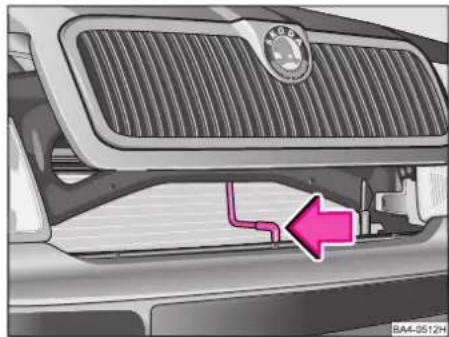
natural_image
Close-up of a car grille and side panel showing a logo and a pink arrow pointing to a pipe outlet (no text or symbols present)To open bonnet, grasp it at the bottom of the radiator grille, raise slightly, push the hook in direction of arrow and raise bonnet.
Take bonnet prop out of its catch and insert it into the opening provided - see illustration (on right).
To close, raise bonnet slightly and release bonnet prop. Press prop into the fixture at the front-end panel. Allow bonnet to drop into the lock from a height of about 20 - 30 cm - do not press on bonnet to close it!
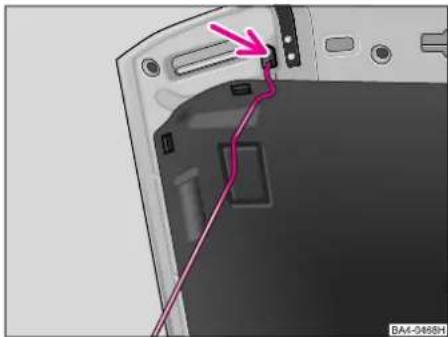
natural_image
Close-up of a device's rear panel showing a cable or cable connector and internal components (no text or symbols visible)Warning
For safety reasons, the bonnet must always be properly closed when vehicle is moving. Always check therefore after closing the bonnet that the lock is engaged.
Should you notice that the bonnet lock is not properly engaged when driving, stop the car immediately and close the bonnet.
GENERAL MAINTENANCE

text_image
Labeled diagram of a car engine bay with numbered components for identification1.6-ltr./74 kW petrol engine
1 - Coolant expansion reservoir
2 - Reservoir for hydraulic fluid of power steering
3 - Windscreen washer reservoir
4 - Engine oil dipstick
5 - Engine oil filler opening
6 - Brake fluid reservoir
7 - Battery
The arrangement in the engine compartment is largely identical on all petrol and diesel engines.
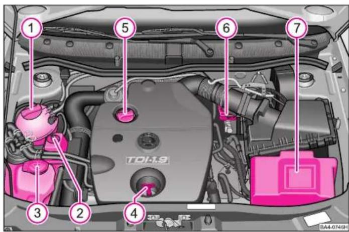
text_image
1 2 3 4 5 6 7 TDI-1.9 8A4-0746H1.9-Itr. TDI 66 kW/81 kW diesel engine
1 - Coolant expansion reservoir
2 - Reservoir for hydraulic fluid of power steering
3 - Windscreen washer reservoir
4 - Engine oil dipstick
5 - Engine oil filler opening
6 - Brake fluid reservoir
7 - Battery
Warning
Particular care is required when performing work in the engine compartment!
■Never open the bonnet if you see that steam or coolant is escaping from the engine compartment - risk of scalding!
You must wait long enough, until the steam or coolant has stopped escaping.
■Switch off engine and withdraw ignition key.
■Apply handbrake properly.
■Move gearshift into Neutral (on models with automatic gearbox move selector lever into position „P“).
■Allow engine to cool down.
■If the engine is still warm:
- do not place your hand into the radiator fan, it might start suddenly. - do not open filler cap of coolant reservoir as cooling system is pressurized - risk of scalding.
■Avoid short circuits in the electrical system - particularly at the battery!
If you wish to work under the vehicle, you must secure the vehicle from rolling away and support it with suitable supporting blocks: the car jack is not sufficient for this - risk of injury!
■If it is necessary to carry out test work when engine is running, there is an additional risk from rotating parts - e.g. ribbed belt, alternator, radiator fan etc. - and from the high-voltage ignition system.
■Never touch the electrical cables of the ignition system.
■Absolutely avoid any jewellery, loose items of clothing or long hair from getting into the rotating parts of the engine - Hazard! Therefore remove any jewellery beforehand, tie up your hair and wear tight fitting clothing.
It is essential to comply with all the warning information given in this manual and with the general rules of safety when carrying out work on the engine.
When topping up fluids, ensure that no mix-ups occur otherwise this may cause severe operating problems!

The floor below the car should be inspected regularly in order to de-leaks in good time. If patches of oil other fluids are visible, the car should taken to a Škoda Dealer for an inspec-
GENERAL MAINTENANCE
LongLife Service\*
The LongLife Service ensures that your vehicle is always in proper roadworthy condition while requiring only minimal effort on your part.
The LongLife Service is determined on the basis of:
- Oil level and pressure sensor - see page 59
- Brake wear indicator - see page 58
- Engine oils complying with the standard VW 503 00 (petrol engines), VW 506 00 (diesel engines, except PDi engines) and VW 506 01 (diesel engines) - see page 138
- Variable service interval display - see page 49
- Battery with so-called „magic eye“ - see page 148.
Further information - refer to Service Schedule. More detailed information is also available from your Škoda Dealer.
Engine oil
Specification
The engine is factory-filled with a brand-name multigrade oil which can be used as an all-seasons oil - except in extremely cold climatic zones. Oils may also be intermixed when topping up (does not apply to models with LongLife Service*).
We recommend using oils from the selection of original oils available at Škoda.
Note
Engine oils naturally also undergo continuous further development. That is why the information contained in this Owner's Manual reflects the technical status at the time of publication.
Škoda Dealers are kept up-to-date by the factory regarding any changes. It is therefore good practice to have the oil change carried out at a Škoda Dealer.
Models with fixed service intervals (QG0, QG2) for oil change
| Designation | Specification for Petrol engines diesel engines | |
| Multigrade high- VW 500 00 VW 505 00 lubricity oils VW 502 00 VW 505 01 | 1) | |
| Multigrade oils ACEA A2 or A32) | ACEA B32) or B42) | |
Models with variable service intervals (QG1)* for oil change
| Specification | |
| Petrol engines VW | 503 00 |
| Diesel engines | VW 506 00 ^1) VW 506 01 |
Warning
Models with variable service intervals (QG1) must only use the above specified oils. It is recommended for the preservation of the specified properties of the oils conforming to specification, only engine oil with the same specification may be used for replenishing. In exceptional cases, only use engine oil conforming to specification VW 502 00 (only petrol engines) or conforming to specification VW 505 01 (only diesel engines) for topping up to max. 0.5 ltr. Other engine oils must not be used - risk of engine damage.
Before a long drive, we recommend that you purchase and carry with you engine oil which complies with the specification for your vehicle. Consequently, you will always have the correct engine oil for refilling.
We recommend using oils from the range of Škoda Genuine Oils offered by your Škoda Dealer.
For further information - see Service Schedule.
1) Except PDi engines (engines with unit injection)
2) This oil may be used only once for topping up within the specified oil change cycle if no approved engine oil is available.
GENERAL MAINTENANCE
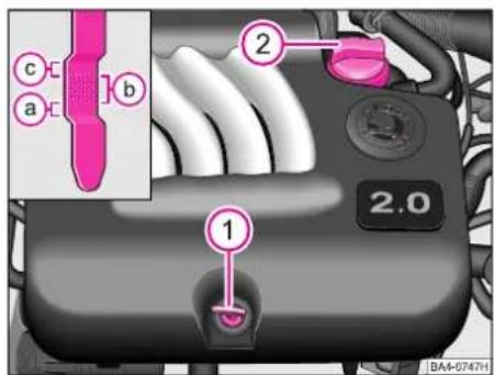
text_image
a b c 2 1 2.0 BA4-0747HThe illustration shows part of an engine compartment with the 2.0-ltr./85 kW engine. For further information regarding the arrangement in the engine compartment - see page 136.
Checking oil level
It is normal that the engine consumes a certain quantity of oil. The oil consumption may be as much as 0.5 ltr/1000 km if operating conditions are disadvantageous (e.g. when driving in town) - see also page 119. The engine oil level should therefore be checked at regular intervals. This is best done each time you refuel and before a long journey.
The position of the dipstick 1 is shown in the illustration.
The car should be standing horizontally when checking the oil level. Wait a few minutes after switching off the engine to allow the oil to flow back into the sump.
Then, withdraw the dipstick, wipe it off with a clean cloth and re-insert it fully.
After this, once again withdraw the dipstick and read off the oil level:
a - Oil must be topped up.
After topping up, it is sufficient if the oil level is somewhere in the range b.
b - Oil may be topped up.
After topping up, the oil level may then be in the range c.
c - Oil must not be topped up.
If the engine is driven particularly hard, as for example during long trips on motorways in summer, when towing a trailer or driving over mountain passes, the oil level should be kept within the range c if possible - not above.
Topping up engine oil
Unscrew the cap 2 of the oil filler opening in the cylinder head cover and pour in the quantity of oil needed. Check the oil level with the dipstick.
The oil level must on no account be higher than the range „c“. Otherwise, oil may be drawn into the combustion chamber and passed through the exhaust system to atmosphere. This can have a detrimental effect on combustion and on the operating life of the catalytic converter.
Warning
When topping up the oil, do not spill it onto hot engine components - danger of fire.
Carefully close the cap of the filler opening and fully insert the dipstick into the inspection hole. Otherwise, oil might flow out when the engine is running.
In the event that you do not have enough fuel, do not drive any further. Switch off the engine and contact a Škoda Dealer for professional assistance, otherwise there is a risk of serious engine damage.
Changing engine oil
The engine oil should be changed at the intervals stated in the Service Schedule or in the service interval display.
Warning
■Only carry out the engine oil change, if you have the required professional knowledge!
■Read and observe the warning notes before working in the engine compartment - see page 137.
■Let the engine cool down - risk of burning from hot oil.
■Wear an eye protection - risk of caustic burns due to oil splashes.
■Oil is toxic! Store old oil in a safe place out of the reach of children and unauthorised persons until you dispose of it properly.
■You must not pour any additives into the engine oil - risk of engine damage! Damage, which results from such product, is excluded from the warranty.
After your skin has come in contact with the oil, you must thoroughly wash your skin.

On no account dispose of oil in the sewage system or into the ground.
Because of the disposal problem, the special tools and the specialist knowledge required, it is best to have the engine oil and filter change carried out by a Škoda Dealer.
Power steering

text_image
MAX MIN BA4-0513HInspecting hydraulic fluid level
The reservoir for the hydraulic fluid of the power steering is located in the right of the engine compartment.
The hydraulic power steering system is filled with hydraulic fluid G 002 000.
The hydraulic fluid level is checked when the engine is at operating temperature and switched off.
GENERAL MAINTENANCE
The fluid level should always be between the „MAX“ and „MIN“ markings. If the level has dropped below the „MIN“ marking, the power steering should be inspected by a Škoda Dealer. It is not sufficient simply to top up the hydraulic fluid.
Note
When the engine is not running (e.g. when the car is being towed or the ribbed belt is broken) the power steering does not operate. The car can still be fully steered however, although greater physical effort is required for steering.
Cooling system
In normal operating conditions the cooling system requires practically no maintenance. The coolant consists of water and a 40 % concentration of coolant additive. This mixture not only offers the necessary antifreeze protection down to -25 °C, but also protects the cooling and heating system from corrosion. In addition, it prevents the formation of scale and increases the boiling point of the coolant.
For this reason, the concentration of coolant should also not be reduced during the summer or in warm countries by topping up with water. The coolant additive concentration should be at least 40 %.
If greater antifreeze protection is required for climatic reasons, the concentration of coolant additive can be increased, but only up to 60 % (antifreeze protection down to about -40 °C). A higher concentration reduces the antifreeze protection and the cooling efficiency is also impaired.
Cars for export countries with a cold climate (e.g. Sweden, Norway, Finland) are factory-filled for antifreeze protection down to about -35 °C.
Coolant
The cooling system is factory-filled with the coolant TL 774-F (G12 PLUS), lilac in colour.
We recommend using the same fluid for topping up the system - G 12 PLUS (lilac in colour).
In the event that it is necessary to top up the system with a different coolant or if there are any unclear aspects, please contact your Škoda Dealer.
The correct coolant is available from your Škoda Dealer.
Other coolant additives may considerably impair the corrosion protection provided.
Any corrosion damage arising from the use of another additive may result in a loss of coolant and consequently in major engine damage.

natural_image
Close-up of a car engine bay with pink spray bottle and valve, no visible text or symbolsChecking coolant level
The coolant reservoir is located in the right of the engine compartment.
The coolant level can be correctly checked only when the engine is not running.
When the engine is cold, the coolant in the expansion reservoir must be in the area of the „MIN“ mark and the crosshatched area. When the engine is warm, the coolant level may be slightly above the crosshatched area.
Loss of coolant
A loss of coolant is first and foremost an indication of a leak. In this case, the cooling system should be inspected by a Škoda Dealer. It is not sufficient merely to top up the coolant.
If there is no leak in the system, losses may also occur if the coolant boils as a result of overheating and is forced out of the cooling system.
If it is not possible to find and rectify the cause of overheating, contact a Škoda Dealer as soon as possible - otherwise major engine damage may result.
Topping up coolant
First of all, switch off the engine and allow it to cool down. Then, place a rag around the cap of the expansion reservoir and carefully unscrew the cap.
Warning
Do not open the cap of the expansion reservoir when the engine is hot - risk of scalding. The cooling system is pressurized!
If, in exceptional cases, it is only possible to top up the system with water, the correct mixture concentration should be restored without delay by using the specified coolant additive.
If there is a major loss of coolant, do not pour in coolant until the engine has cooled down to avoid any engine damage.
Do not top up beyond the crosshatched area!
Excess coolant is forced out of the cooling system by the pressure relief valve in the cap of the expansion reservoir when the coolant heats up.
Screw the reservoir cap tight!
If the event that you do not have enough coolant, do not drive any further. Switch off the engine and contact a Škoda Dealer for professional assistance, otherwise there is a risk of serious engine damage.
GENERAL MAINTENANCE
Warning
The coolant additive and the coolant are poisonous! Do not breathe in coolant vapours, do not swallow coolant, avoid contact with eyes and skin.
If coolant splashes into your eye, rinse out immediately with clear water and contact a doctor.
If coolant is swallowed, you should likewise contact a doctor. The coolant additive should therefore be safely stored in the original containers out of the reach of children.
If the coolant has to be drained out of the cooling system of the car at any time, it should be collected, marked and likewise stored in a safe place.

Drained coolant should not normally be re-used but should be dis- ed of by complying with environmen-protection regulations.
Radiator fan
The radiator fan is driven by an electric motor and controlled by a thermostatic switch in line with the coolant temperature.
Warning
After the engine has been switched off, the fan may continue running for a while - even if the ignition is switched off. It may also start to run again suddenly after a short time if
- the coolant temperature increases due to heat build-up
- when the engine is hot and the engine compartment is heated additionally by strong sunlight.
Special care should therefore be taken when working in the engine compartment.
Brake fluid
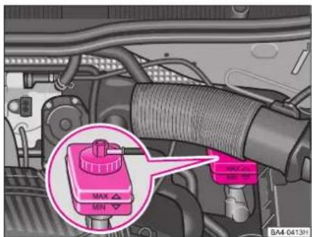
text_image
Diagram of a car engine showing a highlighted MAX/MIN switch with a magnified view highlighting the function.The brake fluid reservoir is located in the left of the engine compartment.
Checking fluid level
The fluid level should always be between the „MAX“ and „MIN“ markings on the reservoir.
A slight drop in the fluid level occurs when driving as a result of wear and tear and automatic slack adjustment of the brake pads. This is perfectly normal.
If the fluid level drops significantly within a short time, however, or if it drops below the „MIN“ marking, there may be a leak in the brake system. Insufficient brake fluid level in the reservoir is indicated by the brake warning light coming on, see also page 61. In such a case, contact a Škoda Dealer without delay and have the brake system inspected.
Warning
Read and observe the warning notes before working in the engine compartment - see page 137.
If the fluid level has dropped below the MIN marking, do not drive any further - risk of accident! Contact a Škoda dealer to obtain professional assistance.
Replacing brake fluid
Brake fluid is hygroscopic and consequently absorbs moisture from the surrounding air over the course of time. An excessive content of water in the brake fluid can also in the long term be a cause of corrosion in the brake system. In addition, the boiling point of the brake fluid is considerably reduced. For this reason, the brake fluid must be renewed every two years.
Warning
When the brake fluid becomes too old, vapour bubbles may form in the brake system when the brakes are used hard. The efficiency of the brakes and thus the vehicle safety is then seriously affected.
Use only fresh brake fluid conforming with Specification FMVSS 116 DOT 4, which is approved by the factory.
Warning
Brake fluid is poisonous!
It must therefore only be stored in the closed original container and, in particular, out of the reach of children.
Please also note that brake fluid attacks the paintwork of the car.

Because of the disposal problem, the special tools and specialist knowledge required, it is best to have brake fluid change carried out by a da Dealer.
It is recommended to have the brake fluid change carried out as part of an Inspection Service.
GENERAL MAINTENANCE
Battery
The battery is located in the engine compartment.
If the vehicle has not been driven for more than 4 weeks, the battery will discharge because some electrical components (e.g. control units) also use current in standstill.
In order to avoid the battery discharging disconnect the negative cable (-) of the battery or continuously recharge the battery.
For jump-starting car with another battery, see the section „Do-It-Yourself“.
Warning
Pay attention to the following warning instructions and safety regulations when carrying out work on the battery.
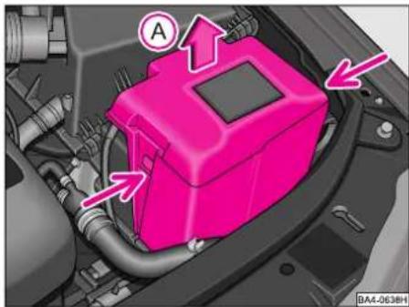
text_image
Diagram of a pink automotive engine compartment with labeled components and directional arrowsAccess to battery
■Pull out the catch on the side of the battery cover (see arrow) slightly. Lift the battery cover up and out - see arrow A.
Warning
Pay attention to the following warning instructions and safety regulations when carrying out work on the battery.
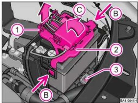
text_image
1 2 3 B C BA4-0641HRemoving battery
■ Pull the cable cover 1 up and out in direction of arrow.
■Disconnect the battery from the vehicle electrical system - pay attention to the Notes on page 148.
■ Press the catch (arrows B) on the side of the holder 2 of the fuse carrier. Open the holder and fuse carrier by raising it (arrow C).
■ Remove the screw 3 from the battery holder and take out the fuse plate.
■Push the battery forward slightly (toward the headlamp) and then lift it up and out.
■Installation is carried out in the reverse order. When re-connecting the battery, refer to the Notes on page 148.
It is not recommended to remove and install the battery (even if the instructions in the Owner's Manual are followed) because severe damage to the battery and fuse box may result in certain circumstances. Contact your Škoda Dealership for this work.

Wear eye protection. Protect your eyes, skin and clothing from sprays from particles which contain ad.
Battery acid is extremely caustic. Wear protective gloves and eye protection. Do not tilt the battery otherwise acid may flow out of the vent openings. If acid splashes into your eyes, rinse them immediately for a few minutes with clear water and then contact a doctor without delay. If acid splashes onto your skin or clothing, neutralise it immediately with soap suds and wash off with plenty of water. If you swallow acid, contact a doctor without delay.
Keep acid and battery away from children.

A highly explosive hydrogen is produced when batteries are charged, which in combination with air pro-xplosive gas mixture.

No fire, sparks, naked flames or smoking. Avoid sparks when handling cables and electrical equipment. Avoid
short circuits. Risk of injury from high-powered sparks.
■It is essential to disconnect the negative cable at the battery before performing any work on the electrical system. When changing bulbs, it is sufficient only to switch off the light.
GENERAL MAINTENANCE

Used batteries are harmful to the environment and should therefore be disposed of by contacting your Škoda Dealer.
Pb

■When disconnecting the battery from the electrical system, first of all disconnect the negative cable (-) and then the positive cable (+).
The battery must not be disconnected when the ignition is switched on and the engine is running otherwise the electrical system (electronic components) will be damaged.
■When re-connecting the battery, first of all connect the positive cable (+) and then the negative cable (-). The connection cables must on no account be mixed up - risk of fire in the wiring!
■Never use a battery which is damaged - risk of explosion! Immediately replace a damaged battery.
■Never charge a frozen or thawed battery - risk of explosion and caustic burns. Replace a frozen battery.
Do not expose the battery to direct sunlight to protect the housing from ultraviolet rays.
Ensure that the battery acid does not come into contact with the paintwork otherwise the paintwork might be damaged.
Checking electrolyte level
In normal operating conditions the battery requires practically no maintenance. It is nevertheless recommended to inspect the electrolyte level from time to time. It should always be between the „MIN“ and „MAX“ markings on the front and back of the battery. If the electrolyte level has dropped below the „MIN“ marking, top up the relevant battery cells to the „MAX“ marking with distilled water.
It is recommended to have the electrolyte level and density inspected and corrected by a Škoda Dealer.

natural_image
Close-up of a car engine bay with a highlighted battery component (no visible text or symbols)Battery with charge state indicator (magic eye)\*
The magic eye is located on the top of the battery. This „magic eye“ alters its colour depending on the charge state and electrolyte level of the battery. The colour indicated serves as a diagnostic aid for Škoda Dealerships.
Knock gently on the magic eye before checking the battery.
If the indication in the window is green, the battery is properly charged. If, on the other hand, the indication is dark, the battery requires to be charged.
If the magic eye is colourless or yellow, this indicates insufficient electrolyte level. Please have the battery checked by a Škoda dealer.
The battery must be topped up with distilled water. If the battery is 5 years or older, we recommend replacing it. Have the electrolyte level inspected and adjusted to the correct level by a Škoda dealer.
Driving in winter
The battery is exposed to particular stresses in winter. In addition, at low temperatures, it is only capable of providing part of the starting power which it has at normal temperatures.
A discharged battery may already freeze at a few degrees below zero.
We therefore recommend having the battery inspected and, if necessary, charged before the start of the winter. This is best done by a Škoda Dealer.
Charging battery
Switch off the ignition and all electrical components before charging the battery.
It is not normally necessary to disconnect the cables from the electrical system when charging with low amperages (e.g. with a mini charger). Always follow the instructions of the charger manufacturer in this case.
Recharge the battery by using a charging current of 1/10 of the battery rated capacity in A (or less) until the battery is fully charged.
A battery charger with a constant charging voltage of 14.4 V can also be used for recharging; the recharging duration is max. 30 hours, according to battery discharge.
Both connection cables should be taken off, however, for quick-charging (only in exceptional cases), in other words charging with high amperages.
Pay attention to the following points:
■The vent plugs of the battery should not be opened for charging.
■Never charge a frozen or thawed battery - risk of explosion and caustic burns! Replace a frozen battery.
■The power cable of the charger should not be plugged in until after the terminal clamps of the charger have been properly connected to the battery terminals:
red terminal
= positive (+)
black terminal
=negative(-).
■After charging, install battery and re-connect correctly - first of all positive (+), then negative cable (-).
GENERAL MAINTENANCE
After connecting the battery
- restore operation of the convenience system - see page 16
- set the time - see page 50
- if the radio is protected by a code, set the code - see operating instructions of car radio
The data of the multifunction display are erased - see page 50.
Replacing battery
If the battery has to be replaced, the new battery should have the same capacity, voltage (12 volts), amperage, design and have a plug seal. Skoda Dealers have available a range of suitable batteries.
Because of the disposal problem involved with old batteries, it is best to have the battery replaced by a Škoda Dealer. Batteries contain substances such as sulphuric acid and lead and must on no account be disposed of in domestic refuse.
Spark plugs
The spark plugs are replaced as part of the Škoda Inspection Service.
■Should it be necessary to replace the spark plugs between the Inspection Service intervals, proceed as follows:
Spark plugs and ignition system are matched to the engine and thus contribute to an exhaust with low emission levels.
Only the spark plugs selected for the particular engine should be used in order to avoid operational problems, engine damage and any infringement of legal requirements in respect of emission levels or radio interference from the spark plugs. Particularly important aspects are the number of electrodes, the thermal value and radio interference suppression.
■Spark plugs may also be subject to technical modifications at short notice. It is therefore recommended to purchase them only from Škoda Dealers as they are always informed of the up-to-date situation.
Ribbed belt
■The ribbed belt is one of the components of the car which is subjected to the most stress. It is therefore necessary to place particularly high quality requirements in respect of the belts.
■When replacing a ribbed belt, it is not sufficient to use any ribbed belt of whatever size. For safety reasons, use only the ribbed belts selected for your car.
■Ribbed belts may also be subject to technical modifications at short notice. It is therefore recommended to purchase them only from Škoda Dealers and to also have the belts changed there as they are always informed of the up-to-date situation.
Windscreen washer system
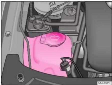
natural_image
Interior view of a car engine bay with visible components and wiring (no text or symbols)The windscreen washer reservoir is located in the right of the engine compartment. It holds about 3 litres, or about 5.5 litres in the case of models with a headlight washer system.
If the vehicle is equipped with headlight washer system, it is necessary to only use certain fluids which do not corrode any polycarbonate connections.
Filling reservoir
When topping up windscreen washer fluid, do not remove the sieve from the reservoir. Impurities might otherwise affect proper operation of the windscreen washer system.
We recommend always adding a wind-screen cleaner with wax-dissolving properties to the water (in winter with antifreeze protection) as clear water is not generally sufficient to quickly and intensively clean the windscreen and the headlight lenses. Refer to the mixing instructions on the wind-screen cleaner pack.
Note
Should windscreen cleaner with antifreeze protection not be available in exceptional cases, it is also possible to add methylated spirits (the concentration of methylated spirits must not be higher than 15 %). Note in this case, however, that the antifreeze protection of this concentration is only down to -5 °C at the most.
Even if your vehicle has heated windscreen washer* nozzles, in winter you should always add antifreeze protection to the water.
On no account use radiator antifreeze protection or other additives!
Windscreen wiper blades
The windscreen wiper blades at the front and rear must be in proper condition if they are to ensure clear visibility. Wiper blades must not be dirtied by dust, insect residues and wax preservative.
To avoid smears, the windscreen wiper blades should be cleaned regularly with a windscreen cleaner. If they are very dirty, e.g. insect residues, the wiper blades can also be cleaned with a sponge or cloth.
If the wiper blades rub or „smear“, this may be caused by wax residues on the windscreen as a result of washing the car in an automatic car wash. For this reason, each time after washing the car in a car wash with wax treatment, remove the wax from the lips of the wiper rubbers and from the windshield and rear window.
In frosty conditions, check that the wiper blades are not frozen to the glass before switching the wipers on for the first time.
For safety reasons, the windscreen wiper blades should be replaced twice a year. Windscreen wiper blades are available from Škoda Dealers.
GENERAL MAINTENANCE

text_image
B A BH1-0052HReplacing windscreen wiper blades Taking off wiper blade
■Fold windscreen wiper arm forward and position wiper blade horizontally.
■ Press the securing spring (arrow A) and at the same time push wiper blade toward windscreen (arrow B). Caution! The windscreen may be damaged when this is done.
Attaching wiper blade
The securing spring must be heard to engage in the windscreen wiper arm.

text_image
A B BA4-3728HReplacing windscreen wiper blade of rear window (Octavia)\*
Removing wiper blade
■Raise windscreen wiper arm.
■Grasp the top part of the windscreen wiper arm with your hand.
■Grasp the wiper blade with your other hand, as close to the middle as possible, and remove the wiper blade by moving the arm in direction of arrow B.
Attaching wiper blade
Connect the windscreen wiper arm and the wiper blade by pushing the two parts together - see arrow A.
Dust, odor and pollen filter\*
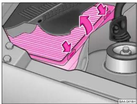
natural_image
Diagram of a car interior showing airflow or fluid flow with arrows indicating direction (no text or symbols present)The dust, odor and pollen filter for the heating and ventilation system is located on the right in the plenum chamber below a two-section cover. The filter should be replaced as stated in the Service Schedule. The filter should also be replaced earlier if the air flow is severely reduced.
The filter should be replaced by a Škoda Dealer as part of the Inspection Service.
Wheels
General information
■New tyres at first do not offer optimal grip and should therefore be run in for the first 500 km at a moderate speed and an appropriately cautious style of driving. You will also profit from longer tyre life.
■Because of design characteristics and different types of tread, the tread depth of new tyres may vary (depending on the type of tyre and manufacturer).
■ Inspect the tyres regularly for signs of damage (foreign bodies, piercing, cuts, splits and dents, particularly in the area of the tyre shoulder). Foreign bodies which penetrate into the tyre may damage it from the inside. Only an expert can assess damage to a tyre and determine whether a repair is possible. If it is not possible to repair a tyre or if this is unsafe, the tyre must then be replaced. The damaged tyre may blow out!
If it is necessary to drive up onto a kerb, do this at a very low speed and at right angles if possible. Avoid driving up onto kerbs with pointed edges. Driving quickly onto kerbs or driving onto a kerb at an oblique angle or driving over obstacles with pointed edges or points (e.g. stones) can result in concealed tyre damage which cannot be detected immediately. This harbours the risk of an accident in the event of the tyre puncturing at a high speed.
■Damage to tyres and wheels is frequently not visible. Unusual vibrations or the vehicle pulling to one side, may be an indication of tyre damage. If you suspect that a wheel is damaged, immediately reduce your speed and stop!
Inspect the tyres (dents, splits etc.). If you cannot find any defect, drive at a slow speed to the nearest Škoda dealer and have the vehicle inspected.
- Keep oil, grease and fuel away from the tyres.
■Replace any lost valve caps without delay.
■If the wheels are taken off, they should be marked first of all so that they can be refitted to rotate in the same direction.
■If wheels or tyres are taken off, always store them in a cool, dry and dark place.
Tyres which are not fitted to a rim, should be stored upright.
Tyre life
The life of the tyres depends essentially on the following points:
Inflation pressure
The tyre inflation pressures are indicated on a sticker on the inside of the fuel filler flap. Further information is available from your Škoda Dealer.
Tyre pressure is an important factor, particularly when driving at high speeds. The inflation pressure should always be checked at least once a month and before setting off on a long journey.
Do not forget to check the air pressure in the spare wheel when checking the tyre air pressures.
■The spare wheel with a standard tyre should always be inflated to the maximum pressure indicated for the car.
■Always check the inflation pressure when the tyres are cold. Do not reduce the pressure of a warm tyre. Adjust the inflation pressure accordingly if there is any major change in the load of the car.
If the tyres are not sufficiently or excessively inflated, this will have a detrimental effect on tyre life and also on the handling of the car.
Warning
When driving continuously at a high speed, a tyre which is not sufficiently inflated has to perform greater flexing work and thus heats up excessively. This can cause sections of the tread to detach and even result in a tyre blow-out.
GENERAL MAINTENANCE
If the tyres are not adequately inflated, your fuel consumption will be higher and you will be unnecessarily polluting the environment.
Driving style
Driving fast through curves, sharp acceleration and sharp braking increase tyre wear.
Balancing wheels
The wheels of a new car are balanced. Various factors when driving may, however, produce an imbalance which makes it felt by steering wobble.
In such a case, the wheels should then be re-balanced as any imbalance in the wheels also results in increased wear and tear to the steering, suspension and tyres. In addition, a wheel has to be re-balanced after fitting a new tyre and each time any repairs are carried out.
Wheel alignment errors
Faulty alignment of the wheels and suspension not only increases tyre wear, often on only one side, but also affects the handling of the car. If any unusual tyre wear exists, contact a Škoda Dealer.

natural_image
Microscopic view of a microfluidic channel with two pink circular annotations highlighting specific features (no text or symbols present)Wear indicators
The base of the tread of the original tyres contains 1.6 mm high „wear indicators“ at right angles to the direction of running - see illustration. These wear indicators are spaced evenly around the circumference of the tyre 6 to 8 times - depending on the make. Markings on the tyre walls, for example the letters „TWI“ or triangle symbols, indicate the position of the wear indicators.
Warning
■New tyres during the first 500 km do not offer optimal grip and should therefore be run appropriately - risk of accident!
■The tyres should be renewed without delay no later than when they are worn down to the wear indicators.
■Worn tyres are detrimental to road-holding particularly at high speeds on wet roads. In addition, the vehicle tends to aquaplane sooner.
■Never drive with damaged tyres - risk of accident!
■Immediately replace the damaged rims or tyres.

natural_image
Top-down diagram of a car with four red-labeled sensors arranged in circular motion arrows (no text or symbols)Switching around tyres
If the wear to the tyres of the front wheels is significantly greater, it is recommended to switch the front tyres to the rear wheels, as shown in the illustration. This ensures that the life of all the tyres is approximately the same.
It may be beneficial to switch over the tyres diagonally if certain types of wear are present on the tyre tread (this only applies to tyres which do not have to be fitted to run in a particular direction). Details are available from Škoda Dealers.
Replacing a wheel or tyre
Tyres and wheels (disc wheels) are important design elements. For this reason, use only tyres and wheels approved by the vehicle manufacturer. They are exactly matched to your model of car and thus make a significant contribution to good road-holding and to safe handling.
Škoda Dealers have available up-to-date information of which makes of tyres are approved by us. Many Škoda Dealers also keep in stock an attractive range of tyres and wheels.
■ Fitting and repairing tyres requires specialist knowledge and special tools. Such work should therefore only be carried out by qualified persons in Škoda Workshops.
Because of the problems of disposing of old tyres, the special tools and specialist knowledge required, it is best to have tyres replaced by a Škoda Dealer.
■ For road safety reasons, do not replace individual tyres, if possible, but at least both tyres on the same axle. The tyres with the deeper tread should always be fitted to the front wheels.
■ Only combine radial tyres of the same design, size (rolling circumference) and, if possible, with the same tread pattern on all four wheels.
■ Never fit used tyres whose previous history is not known. Do not fit any used tyres if you are not aware of their „history“. Tyres age even if they have not been used at all or only very little. The spare wheel should likewise only be used in an emergency and by then adopting appropriately cautious style of driving.
GENERAL MAINTENANCE
■ Knowledge of the tyre inscription and its meaning makes it easier to choose the right tyres. Radial tyres have the following inscription on the tyre wall:
e.g. 175 / 80 R 14 88 T
175 = Tyre width in mm
80 = Height/width ratio in %
R = Tyre design code for Radial
14 = Wheel diameter in inches
88 = Ply rating
T = Speed code
The following speed categories apply to tyres:
Code letter Q - max. 160 km/h
Code letter R - max. 170 km/h
Code letter S - max. 180 km/h
Code letter T - max. 190 km/h
Code letter H - max. 210 km/h
Code letter V - max. 240 km/h
The tyres may be damaged if you drive at more than the maximum speed for the particular tyre.
The date of manufacture is also indicted on the tyre wall (possibly only on the inside of the wheel).
DOT 40.04 means that the tyre was manufactured in the 40^th calendar week of 2004.
Warning
Tyres which are more than 6 years old, should only be used in exceptional cases and by adopting a cautious style of driving.
If the car is retrofitted with tyres or wheels other than the factory-fitted type, pay attention to the following points:
Warning
■For technical reasons, it is not permitted on any account to use tyres or wheels on your car which have not been approved by the manufacturer for the particular model.
■ Wheels and wheel bolts are matched to each other. If different wheels are fitted to the car (e.g. light alloy wheels or wheels fitted with winter tyres), it is then necessary to use the matching wheel bolts of the correct length and shape of spherical cap. In view of the fact that the wheels and wheel bolts, including security bolts, are matched for all the wheels approved by the manufacturer (sheet steel, steel and light alloy wheels), never use wheel bolts which are not approved by the manufacturer. These are universal for all types of approved wheels and are tightened in the same way as described in the section DO-IT-YOURSELF.
■Using tyres and/or wheels which have not been approved by the manufacturer for your model of car can be detrimental to the safety of the vehicle. It may also affect official approval for use of the vehicle on public roads!
■If wheel trims are subsequently fitted, it is essential to ensure that the air flow remains adequate for cooling the brakes.
Škoda Dealers are informed of the technical possibilities for converting and retrofitting tyres, wheels and wheel trims.
Winter tyres ^1)
Warning In winter conditions, winter tyres will significantly improve the handling of your car.
■Only radial-type winter tyres may be fitted.
1) Pay attention to any varying legal requirements when using winter tyres.
■To achieve the best possible handling and grip, fit winter tyres to all four wheels (same manufacturer, tyre size, tread pattern).
■Winter tyres largely lose their good grip properties in winter if the tyre tread has worn down to a depth of 4 mm. The following speed restrictions apply to winter tyres.
■You can fit winter tyres of a lower speed category provided that you also do not drive at a speed in excess of the maximum speed for these tyres even if your car is able to be driven at a higher actual maximum speed. The tyres may be damaged if you drive at a speed beyond the maximum speed rating of the tyres.
■All-weather tyres may be used in winter in place of winter tyres.
■In the event of a puncture, refer to the information for using the spare wheel on page 156.
Summer tyres should also be fitted again in good time as an environmental protection measure as the rolling noises are normally less, tyre wear is reduced and fuel consumption is improved.
Further information is available from Škoda Dealers.
Snow chains ^2)
It is possible to fit snow chains to all the tyre sizes listed (with the exception of tyre sizes 205/60 R15 and 205/55 R16).
5.5J x 16 ET 36 wheels (Genuine Accessories) when used in combination with 205/55 R16 tyres enable snow chains to be fitted to the Octavia RS including other vehicle models Octavia and Octavia Estate.
The chains must only be fitted to the front wheels.
Use only fine-link chains which do not exceed more than 15 mm (including chain lock).
We recommend purchasing the snow chains as Genuine Accessories from a Škoda Dealer.
The full wheel trim should be removed when driving with snow chains.
Snow chains should be taken off when driving on roads free of snow as they otherwise impair the handling of the car, damage the tyre and are quickly destroyed.
2) Please observe any varying legal requirements in respect of the approved vehicle speed when driving with snow chains.
GENERAL MAINTENANCE
Motoring abroad
Please give consideration to the following points when driving abroad with your car:
■If your car is fitted with a petrol engine and catalytic converter, it is important that unleaded petrol is available on your route - see also page 128. Information regarding the availability of unleaded petrol can be obtained from automobile associations.
In certain countries it is also possible that the Škoda Dealership network is not fully developed. Certain replacement parts may therefore not be available or the personnel of the Škoda Dealer may be able to carry out repair work only to a limited extent.
ŠKODA AUTO a. s. in the Czech Republic and the relevant importers will gladly provide you with the necessary information regarding preparing your car technically for motoring abroad, the servicing required and repair facilities.
The addresses of the Škoda dealers in the ČR can be found in the brochure „Škoda dealers in ČR“.
For all other countries, you will find a contact address in the brochure „Travelling assistant“ or in the local „Workshop listing“.
Masking over headlights
Adapt your headlights for using the car in countries in which the traffic drives on the left-hand side: If you use your car in countries in which traffic drives on the left-hand side of the road, other road users coming toward you may be dazzled when you use the headlights of your car which has been designed for driving on the right-hand side of the road. In order to eliminate this problem, you should mask over the left-hand wedge-shaped areas of the headlight lenses with an opaque adhesive strip.
The illustrations show how to mask over the headlights of a car designed for driving on the right-hand side of the road, when it is used in a country in which traffic drives on the left.
Adapting headlights with gas discharge lamps\* (applies to left-hand and right-hand drive models)
If you use your car in countries in which traffic drives on the left-hand side of the road, other road users coming toward you may be dazzled when you use the headlights of your car which has been designed for driving on the right-hand side of the road.
In order to eliminate this problem, the headlights must be adapted.
This adaptation is achieved by switching over the shroud for low beam in the head-light module.
This measure is carried out by your Škoda Dealer. He can also provide you with more detailed information on this matter.
Adapting the headlights with gas discharge lamps is not a substitute for headlights which are designed for driving on the right or on the left, respectively.
GENERAL MAINTENANCE
Mobile phones and two-way radios
Installation of mobile phones and two-way radios requires official approval and should be carried out by an authorized workshop, e.g. by a Škoda Dealer.
Škoda Auto has approved the operation of mobile phones and two-way radios for your car with a professionally installed external aerial and a maximum transmission power of 10 watts.
Use of a mobile phone or a two-way radio can result in operational problems to the electronic systems of your car in the following situations:
- no external aerial
- external aerial incorrectly installed
- transmission power in excess of 10 watts.
For this reason, you must not use a mobile phone or two-way radio inside the car if no external aerial is fitted or if it has been incorrectly installed.
Warning
Using a mobile phone or two-way radio inside the car without a separate external aerial may also be harmful to your health as a result of excessive electromagnetic fields!
In addition, it is only possible to achieve the optimal range of such equipment with an external aerial.
Note
Please pay attention to the operating instructions of the mobile phone or two-way radio!
If you wish to use a mobile phone or two-way radio with a transmission power of more than 10 watts, please always discuss this with your Škoda Dealer as he is instructed of the technical facilities which exist for retrofitting mobile phones and two-way radios.
Warning
■Please always devote maximum attention to driving your car!
■ Never install mobile phone mounts on the covers of the airbags or in the deployment area of the airbags otherwise there is an increased risk of injury if the airbag is deployed in the event of an accident!
Accessories, modifications and parts
Škoda cars are designed to reflect the latest state of safety engineering. To ensure that this is always the case, do not make any modifications to your car without proper consideration. If you wish to retrofit accessories to your car, make any technical modifications or have to subsequently replace parts, please pay attention to the following points:
■Before purchasing accessories and before making technical modifications, always ask the advice of a Škoda Dealer.
This is particularly important when purchasing accessories abroad.
GENERAL MAINTENANCE
Warning
In your own interest we recommend using only Škoda Accessories ^1) and Genuine Škoda Parts expressly approved for your car. Such accessories and parts are your guarantee of reliability, safety and suitability specifically for your Škoda.
■Despite constantly observing the market, we are not in a position to assess and also not to warrant other products, even if in exceptional cases an official approval has been provided by a technical inspection authority or other public institution.
■Approved Škoda Accessories and Genuine Škoda Parts are available from Škoda Dealers who can also carry out professional fitting.
■All the genuine accessories which are listed in the catalogue, such as tilting roofs, spoilers, wheels etc. have to have an official approval.
■Radios, aerials and other electrical accessories should also only be installed by authorized workshops.
■It is important to observe the specifications issued by the car manufacturer if any technical modifications are made to your car.
This ensures that no damage occurs to your car, that the safety and roadworthiness of your car is maintained and that the modifications are approved. Škoda Dealers are also able to carry out such work in a professional manner or, in exceptional cases, to provide you with the address of a specialist workshop.
■Any damage resulting from technical modifications which have not been approved by us, are not covered by the warranty.
Technical changes
Interference in the electronic components and their software can lead to operational faults.
This interference can also impair not directly affected systems because of the networking of the electronic components.
This means that the operating safety of your vehicle can be considerably jeopardised, a greater wear of vehicle parts can occur and finally the vehicle registration documents expire.
We trust that you will understand that your Škoda dealer cannot be liable for damage resulting from unprofessional work.
We therefore recommend that you have all work carried out with Škoda original parts at your authorised Škoda dealer.
Warning
Work or modifications on your vehicle, which have been carried out unprofessionally, can cause operational faults - risk of accident!
First-aid box, warning triangle

natural_image
Close-up of a pink plastic bag with glossy finish, mounted on a gray vehicle door (no text or symbols visible)Applies to models fitted with all-wheel drive\*
The first-aid box is attached to the inside of the cover of the storage compartment on the right.
Applies to models fitted with front-wheel drive
A commercially available first-aid box together with a warning triangle fit together in a foam base below the floor covering of the luggage compartment.
Note
The first-aid box, the warning triangle and the bulbs are not supplied with the car!
The warning triangle is part of the standard equipment only on all-wheel drive vehicles.
Car tool kit

natural_image
Close-up of a pink plastic mechanical component inside a car tire (no visible text or symbols)The car tool kit and car jack are stored in a plastic basket in the spare wheel.
This also provides space for the detachable ball head of the trailer hitch (only on certain models) or also, for example, for a trailer hitch which has been sold as a Škoda Genuine Accessory.
Depending on the model version, the ball head of the trailer hitch may also be stored in the well behind the spare wheel. In this case, you then have to use the first-aid box stored in the upholstery.
More detailed information is available from your Škoda dealer.
Warning
■The car jack supplied is only designed for your model of car. On no account attempt to lift heavier vehicles or other loads.
■Ensure that the vehicle tool kit is safely attached in the luggage compartment.
DO-IT-YOURSELF
Tyre repair spray\*
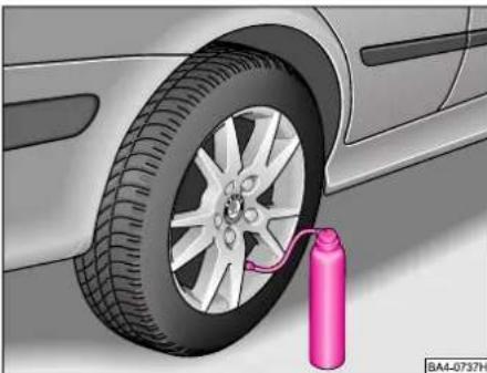
natural_image
Illustration of a car tire mounted on a car wheel with a pink gas cylinder attached (no text or symbols)■The tyre repair spray is precisely for fast repairs on small tyre defects up to 5 mm. The spray does not replace a permanent tyre repair, the repair serves only as an intermediate solution until the next service.
■The repair can be directly performed on the vehicle. Carefully read the enclosed instructions for direction of use.
On front-wheel drive vehicles, the spray is located in the well at the front right of the polypropylene part behind the spare wheel, and on 4x4 vehicles, in the boot on the left.
Tyre repair set\*
Certain models are equipped with a tyre repair set which includes a compressor and a repair flask, instructions and accessories. On front-wheel drive vehicles this set is located in the well at the front right of the polypropylene part behind the spare wheel, and on 4x4 vehicles, in the boot on the left next to the first-aid box.
■Apply the handbrake before jacking up the car. Never start the engine when the car is jacked up - risk of accident.
■If it is necessary to carry out work underneath the vehicle, ensure that it is supported on suitable stands.
Spare wheel
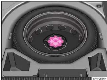
natural_image
Close-up of a mechanical component with a pink circular feature and concentric rings (no visible text or symbols)The spare wheel is stowed in the well below the floor covering of the luggage compartment and is secured by a handwheel.
■To ensure that the spare wheel is always ready for use, check the inflation pressure at regular intervals.
Vehicles with tyres 205/60 R15 and wheel trims 6.5Jx15 have an emergency wheel as a spare wheel, which has different dimensions and which is provided with a warning sticker.
Please pay attention to the following instructions, if you are going to use an emergency wheel:
■After fitting on the wheel, the warning sticker must not be concealed (e.g. by the wheel trim).
■Do not drive with this spare wheel at more than 80 km/h - risk of accident.
Avoid acceleration at full throttle, sharp braking and fast cornering.
■The inflation pressure for this spare wheel is identical to the inflation pressure of the standard tyres.
■Use this spare wheel only to reach the nearest service station, as it is not intended for continuous use.
Changing a wheel
Warning
In the case of a flat tyre or puncture, park the vehicle off the road, switch on the hazard warning lights and place the warning triangle in position - note any statutory requirements.
■All the vehicle occupants should leave the car and move to a safe area (e.g. behind safety barrier).
■ Apply handbrake firmly and engage a gear. Chock the opposite wheel with a stone or similar if the car is standing on a slope.
■Never start the engine when the car is jacked up - risk of accident!
■If towing a trailer, unhitch the trailer from the car before changing the wheel.
■Carry out wheel change on a flat, level surface, as far as possible.
■Remove the car tool kit and spare wheel from the luggage compartment.

natural_image
Illustration of a car tire with a pink tool inserted, showing the wheel and tire (no text or symbols)■Attach the wire hook (from the car tool kit) at the edge of the full wheel trim* opposite the air valve. Push the wheel wrench through the wire hook and pull off the wheel trim - see illustration.
■If light-alloy wheels are fitted, use the plastic clip supplied to pull off the covers for the wheel bolts.
■Unscrew the safety wheel bolts* - see page 166.

natural_image
Close-up of a car tire with a pink arrow pointing to the wheel rim (no text or symbols visible)■Fit wheel wrench onto the wheel bolt as far as the stop and turn to the left. Hold the wrench as close as possible to its end for this operation. If the bolts cannot be slackened, you can carefully apply pressure to the end of the wheel wrench with your foot. Ensure that you are standing properly and hold tight on the car. Slacken the wheel bolts about one turn.
DO-IT-YOURSELF
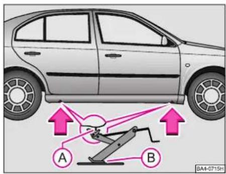
text_image
A B BA4-071SH■Fit the car jack onto the car. Recesses are provided on the lower sill (at the front and rear). Below this is the point at which the car jack should be positioned - see arrows in the illustration.
■Position the car jack so that its claw fits around the web of the lower sill A and the moving base plate of the car jack B is positioned flat on the ground.
Warning
■Always raise the vehicle with the doors closed - risk of injury.
■Take suitable measures to prevent the base of the lifting jack from slipping off - risk of injury!
■Place the lifting jack only on a solid and even surface.
■Not positioning the lifting jack at the specified points can result in damage to the vehicle. In addition, the jack may slip off if it does not have sufficient grip - risk of injury!
■Never start the engine if the vehicle is lifted - risk of accident.
■Never lie under the vehicle if the vehicle is only lifted with the vehicle lifting jack.
■It is important to support the vehicle with suitable supporting blocks if you wish to work under the lifted vehicle - risk of injury!
- If the surface is soft, place a large solid base below the foot of the jack.
- Rotate the crank to raise the claws of the jack sufficiently so that the jack can just still be fitted below the car.
- The claw of the jack must be fitted around the vertical web of the lower sill so that the jack cannot slip off when the car is raised.
- The base of the jack should be resting fully on a firm surface.
- Align jack and at the same time raise the claw of the jack further until the claw is touching the web.
■Jack up car until the wheel is just clear of the ground.
■Remove wheel bolts (after slackening) 1), place them down on a clean surface (cloth, paper, wheel cap) next to the car jack and take off wheel.
■Fit on spare wheel and attach wheel bolts ^1) .
■Tighten all the wheel bolts slightly. The wheel bolts should be clean and turn freely.
■On no account grease or oil them!
■Lower car and tighten the wheel bolts diagonally.
■Press on the full wheel trim* first at the valve opening and then apply pressure around the entire circumference so that the trim locks in position.
■Place the wheel removed in the spare wheel well and secure with the handwheel.
Notes
■After changing a wheel, pay attention to the following points:
- Check the inflation pressure of the spare wheel fitted.
- Have the tightening torque of the wheel bolts checked with a torque wrench as soon as possible. The tightening torque for steel and light alloy wheels is 120 Nm.
■Have the faulty wheel repaired as quickly as possible.
Warning
In case of incorrect treatment of the wheel bolts, the wheel can loosen when the car is moving - risk of accident!
Wheel bolts must be clean and must turn easily. However, they must never be treated with grease or oil.
If the wheel bolts are tightened to a too low tightening torque, the trims can loosen when the car is moving - risk of accident! A tightening torque, which is too high, can damage the bolts and threads and this can result in permanent deformation of the contact surfaces on the trims.
If it is intended to subsequently fit wheels or tyres other than the factory-fitted versions to the car, it is essential to read the remarks on page 156.
DO-IT-YOURSELF
Anti-theft lock of wheels\*
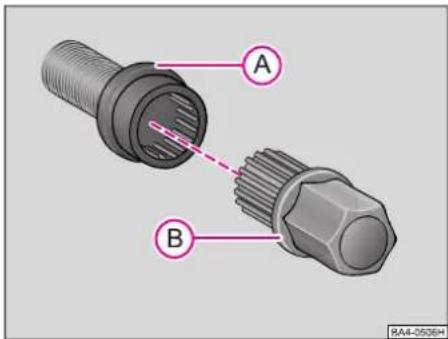
text_image
A B RA4-0506HWheel locking bolts
A - Wheel bolt
B - Adapter
If wheel locking bolts are fitted to a car (one bolt for each wheel), these can only be slackened and tightened using the adapter supplied. It is good practice to note the code No. indicated on the adapter.
If the adapter or the wheel locking bolt is lost, contact your Škoda Dealer.
■Pull off the wheel caps and fit adapter B onto the wheel bolt A. Turn adapter until the splines engage.
■Slacken or tighten the wheel bolt by fitting the wheel wrench to the hexagon of the adapter.
■After removing the adapter, fit a protective cap onto the wheel bolt.
Note
■It is essential that the locking bolt is tightened to a torque of 120 Nm. If this torque is exceeded, the bolt and the adapter may in certain circumstances be damaged.
■On steel wheels, the theft-deterrent wheel bolt must always be installed in the hole, which is close to the valve. Otherwise the full wheel trim cannot be mounted and the full wheel trim can be damaged during the assembly.
■You can also obtain the wheel lock bolt set as a Genuine Accessory from your Škoda dealer.
Fire extinguisher\*
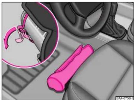
natural_image
Interior view of a car showing a pink car seatbelt and steering wheel (no text or symbols visible)The fire extinguisher is located in the holder below the driver seat and is secured with straps.
■Carefully read the instructions regarding the fire extinguisher.
■The fire extinguisher must be inspected once a year by a regular person or a company. Please pay attention to the different legal regulations.
■The fire extinguisher is only delivered in certain countries.
■Pay attention to the expiration date of the fire extinguisher. If the fire extinguisher is used after the expiration date, its proper function is no longer assured.
Warning
If the fire extinguisher is not correctly attached, in case of sudden manoeuvres or an accident, it can be thrown through the interior compartment and cause injuries.
Fuses
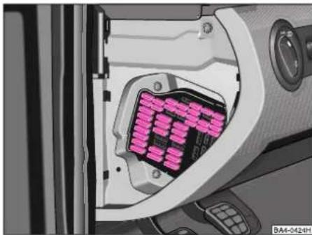
natural_image
Close-up of a car's internal battery pack with pink LED indicators (no text or symbols visible)The individual electrical circuits are protected by fuses.
The fuses are located on the left-hand face end of the instrument cluster below the cover.
Space is provided on the right for spare fuses - see page 168.
Additional fuses are located in the engine compartment on the battery. We recommend having these fuses replaced by a Škoda Dealer.
Replacing a fuse
■Switch off the ignition and the relevant electrical component.
■To remove the cover, place a screwdriver against the cover (arrow on cover) and carefully lever it off.
■Refer to the list of fuses as shown in illustration to find which fuse belongs to the faulty component - see illustration on page 168.
■Remove the blown fuse.
■A blown fuse is recognizable from the melted metal strip - replace with a new fuse of the same rating.
Notes
■If a newly inserted fuse blows again after a short time, the electrical system should then be inspected as soon as possible by a Škoda Dealer.
■On no account „repair“ fuses as this may cause major damage to another point of the electrical system.
■Certain of the electrical components listed are fitted only to particular model versions or are optional equipment.
■We recommend always carrying with you a box with replacement fuses, which is available from Škoda Dealers 1).

text_image
8 12 16 20 5 9 13 17 21 1 3 6 10 14 18 22 2 4 7 11 15 19 23 24 31 38 25 32 39 26 33 40 27 34 41 28 35 42 29 36 43 30 37 44 Res Res Res Res Res Res BA4-0425HFuse assignment
No. Electrical component A
1 - Mirror and spray nozzle heater,
relay for cigarette lighter
el. seats 10
2 - Turn signal lights 10
3 - Stowage compartment light...... 5
4 - Licence plate lights 5
5 - Seat heaters, Climatronic, Navigation system, recirculated air flap, multifunction steering wheel, exterior mirror heaters ..... 7.5
6 - Central locking control unit 5
7 - Reversing lights, parking aid ..... 10
8 - Mobile phone 5
9 - ABS/ESP 5
10 - Petrol engine: control unit ..... 20
Diesel engine: control unit..... 5
No. Electrical component A
11 - Dash panel insert, selector lever lock solenoid (automatic gearbox) 5
12 - Power supply for diagnosis, mobile phone 7.5
13 - Brake lights 10
14 - Interior light, central locking ..... 10
Interior light (without central locking) ..... 10
15 - Instrument cluster, automatic gearbox, steering lock angle sensor, rear-view mirrors .... 5
16 - Air conditioning, electric water pump 10
17 - Police 5
18 - Right main beam 10
19 - Left main beam 10
20 - Right low beam, headlight range control.... 15
21 - Left low beam 15
22 - Right parking light 5
23 - Left parking light 5
24 - Wiper system, washer pump ..... 20
25 - Heater fan 25
26 - Rear window heater 25
27 - Rear window wiper 15
28 - Fuel pump 15
29 - Petrol engine - engine electronics, ignition 15
Diesel engine - engine electronics 10
No. Electrical component A
30 - Power sliding/tilting roof ..... 20
31 - Automatic gearbox.... 20
Haldex coupling .... 5
32 - Petrol engine - injectors .... 10
Diesel engine - injection pump,
control unit .... 30
33 - Headlight cleaning system ..... 20
34 - Petrol engine - engine electronics .... 10
Diesel engine - engine electronics .... 10
35 - Trailer socket, socket in luggage compartment.... 30
36 - Fog lights 15
37 - S contact 1) 10
38 - Luggage compartment light, central locking, remote fuel filler flap release 15
39 - Hazard warning signals ..... 15
40 - Horn 20
41 - Cigarette lighter 15
42 - Radio 15
43 - Petrol engine: engine electronics .... 10
Diesel engine: engine electronics .... 10
44 - Seat heaters 15
Colour coding of fuses: A
light brown: 5
dark brown: 7.5
red: 10
blue: 15
yellow: 20
white: 25
green: 30
Notes
The fuse assignment differs depending on the version of your car.
The pliers for removing fuses and replacement fuses are not contained in the car equipment.
Replacing a bulb
The relevant light should always be switched off first of all before replacing a bulb.
Do not grasp the glass of the bulb with your bare fingers (even the minutest spot of dirt reduces the operational life of the bulb). Use a clean cloth, napkin or similar.
A bulb should only be replaced by a lamp of the same design. The designation is given on the base of the bulb or on the glass.
Warning
H4 bulbs are pressurized and may burst when they are replaced. For this reason, always wear gloves and eye protection when changing a H4 bulb.
Models with Xenon headlamps\*
If your car is fitted with xenon headlights, have the bulb (low beam, side light and main beam) replaced by a Škoda dealer.
We recommend always carrying with you in the car a box with a set of spare bulbs, which you received together with your car, or which is available from your Škoda Dealer ^1 .
DO-IT-YOURSELF
Table of bulbs
| Front Halogen Xenon headlight headlight | ||
| Low beam | H4 | D2S |
| Main beam H1 | ||
| Side lights W5W | ||
| Turn signal lights | PY21W | |
| Fog lights H3 | ||
| Rear light Octavia Octavia unit Estate | ||
| Rear lights P21W | ||
| Turn signal lights | PY21W | |
| Brake lights P21W | P21/5W | |
| Side lights | P21/4W | |
| Fog lights P21W | ||
| Others Octavia | OctaviaEstate | |
| Side turnsignal lights | WY5W | |
| License platelight | W5W | |
| Additionalbrake light | W2,3W | LED |
| Interior light | C10W | |
| Reading light | W5W | |
| Boot light C5W | C10W | |
| Door warninglight | C5W | |
| Glove box light | C3W | |
| Interior mirrorlight | W2,3W | |
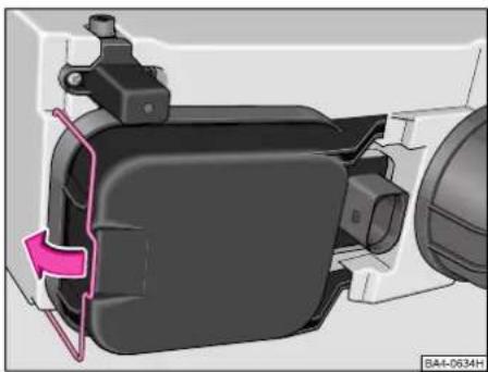
natural_image
Mechanical assembly diagram showing a black component with a pink highlighted section, no visible text or symbolsMain headlight with cap of low beam, main beam and side light
Before replacing the bulb (main beam and low beam, or main beam and low beam, or side light) you have to remove the protective cover from the rear part of the headlight - refer to the text which follows.
■Open bonnet.
■Press locking plate off the cap and tilt it out in direction of arrow.
■Remove cap of headlamp by pushing it out toward the middle of the vehicle.
Installation is carried out in the reverse order.
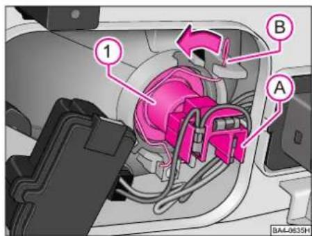
text_image
1 B A BA4-0635H■Open bonnet.
■Take off cap for headlight.
■ Hold wire spring clamp B and unplug connector A.
■ Detach wire spring clamp B by pressing toward bulb and fold down in direction of arrow.
■ Take out bulb 1 and insert new bulb so that the locating lugs at the bulb disc engage in the recess of the reflector.
■Fold wire clamp over the base of bulb and push forward until the clamp engages.
■Plug in connector.
■Fit on cap for the headlight.
■Have the headlight beam setting checked at a Škoda Dealer.
DO-IT-YOURSELF
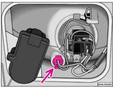
natural_image
Close-up of an electrical plug inserted into a socket with wiring, showing internal components and a pink arrow pointing to a component (no text or symbols visible)Front side light bulb
■Open bonnet.
■Take off cap for headlight.
■Pull out light socket with bulb - see arrow.
■Remove the faulty bulb from the socket.
■Insert new bulb.
■Fit socket with new bulb into its fixture.
■Fit on cap for the headlight.
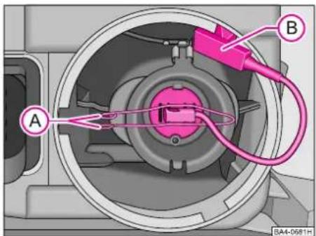
text_image
A B BA4-0581HFog lights\*
■Open bonnet.
■Turn plastic cap for headlight toward middle of vehicle and then take off.
■Separate plug connection B
■ Release spring wire clamp A of bulb fixture and fold down.
■Take out halogen bulb with cable. Insert new bulb so that the locating lugs in the reflector are positioned in the matching recesses in the bulb disc.
■Fold spring wire clamp over bulb disc. Press wire clamp together and lock it again in place.
■Plug in connector.
■Fit on cap.
■Have the beam setting of the fog lights checked by a Škoda Dealer.

natural_image
Interior view of a car showing internal components and a highlighted part (no text or symbols visible)Front turn signal lights
■Open bonnet.
■Remove securing screw 1.
■Push turn signal light housing in direction of arrow.
■Turn bulb holder slightly to the left and take off.
■Press faulty bulb into the socket, turn to the left and remove.
■Insert new bulb and turn fully to the right.
■Insert bulb holder and turn slightly to the right as far as the stop.
■Fit turn signal light on outside with the two retaining lugs at the side into the recesses of the headlight.
■Tighten screw 1.
Side turn signal lights
Have the bulb replaced by a Škoda Dealer.
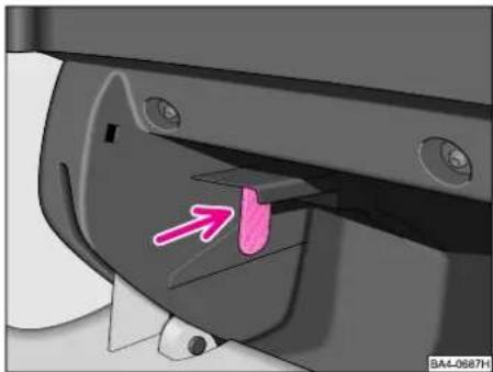
natural_image
Close-up of a mechanical component with a pink arrow pointing to a specific part (no text or symbols visible)Stowage compartment light\*
■Insert screwdriver at side between light and stowage compartment - see arrow. Carefully remove light.
■Unplug connector by compressing the catches at the side.
■Replace bulb.
■Plug in connector.
■Press light into the stowage compartment from below.
We recommend having the bulb replaced at a Škoda Dealer.

text_image
1 BA4-0639HFront door warning light\*
■Press off light first of all at one side and then at the other side - see arrows. Carefully take off housing in direction of arrow 1.
DO-IT-YOURSELF
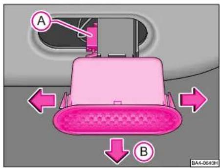
text_image
A B BA4-0640H■Separate plug connection A.
■Press off spring lock of lens on one side and then on the other side - see arrows. Carefully take off lens in direction of arrow B.
■Replace bulb.
■Fit lens into housing again until it locks in place.
■Plug in connector.
■Carefully press light into door trim panel.

natural_image
Interior view of a vehicle showing airflow direction arrows (no text or symbols)Rear lights
■Open tailgate.
■Push cover to the side.
■Press spring catches at bulb holder in direction of arrow and take out bulb holder.
■Press faulty bulb into the base, turn to the left and remove.
■Insert new bulb and turn fully to the right.
■Insert bulb holder so that the spring catches engage.
■Push back cover.
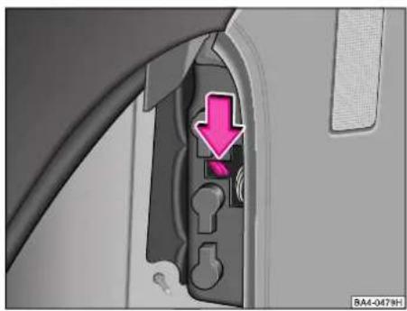
natural_image
Close-up of a car door panel with a pink downward arrow indicating a warning or drop, no visible text or symbols.Rear lights (Estate)
■Open tailgate.
■Open side storage compartment
■Press spring catches at bulb holder in direction of arrow and take out bulb holder.
■Press faulty bulb into the base, turn to the left and remove.
■Insert new bulb and turn fully to the right.
■Insert bulb holder so that the spring catches engage.
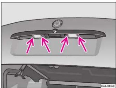
natural_image
Top-down view of a car rear bumper with three pink arrows pointing to the front panel (no text or symbols visible)Licence plate lights
■Open tailgate and unscrew lens of light.
■Pull faulty capless bulb out of the bulb holder and insert new bulb.
■Insert lens of light again as far as the stop and ensure that the rubber seal is correctly installed.
■Screw on lens of light with slight pressure.
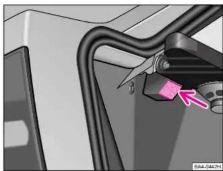
natural_image
Close-up of a mechanical component with a pink arrow pointing to a highlighted section (no text or symbols visible)Luggage compartment light
■Open tailgate.
■Insert screwdriver into the recess on the side of the light - see arrow. Carefully press out light.
■Unplug connector of the bulb.
■Replace bulb.
■Plug in connector.
■First of all insert the left-hand side of the light and press in fully.
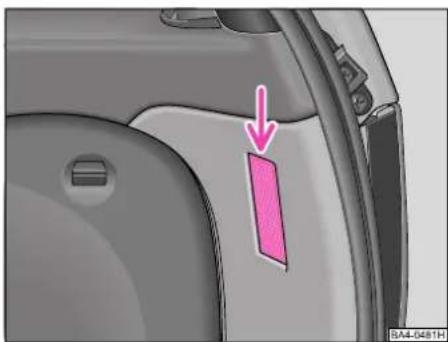
natural_image
Close-up of a car door panel with a pink arrow pointing to a highlighted section (no text or symbols visible)Boot light (Estate)
■Open tailgate.
■Position screwdriver into the opening next to the light - see arrow. Carefully press out light.
■Unplug connector of the bulb.
■Replace bulb.
■Plug in connector.
■First of all insert bottom side of the light and press in fully.
DO-IT-YOURSELF
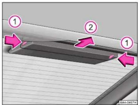
text_image
1 2 1 BA4-0467HAdditional brake light
■Press both plastic spring catches of the housing of the light in the direction of arrows 1.
■Take off bulb holder with bulbs in the direction of arrow 2.

natural_image
3D diagram of a mechanical component with pink connectors and a labeled section (BA4-0475H), no readable text or symbols present.■Take faulty bulb out of the holder.
■Insert new bulb.
■Insert bulb holder into the housing. The spring catches should lock in place.
Additional brake light (Estate)
We recommend having the bulbs replaced by a Škoda Dealer.
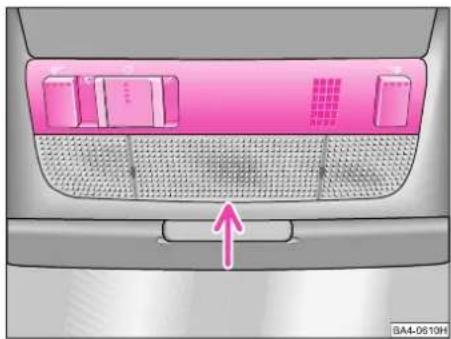
natural_image
Top-down view of a car backrest with pink filter zones and a white arrow pointing to a button (no text or symbols)Interior light and reading light
■Pull lens down and off the housing (at the arrow shown in the illustration).
■Replace the bulb for the interior light.
■Pull bulb for the reading light out of its socket and insert new bulb.
■Press the lens of the light into the housing again until it locks in place (ensure it is correctly fitted on).

natural_image
Diagram of a car interior with a pink arrow pointing to a circular component, no text or symbols presentInterior light (rear)\*
■Insert a screwdriver between light and headlining - see arrow. Carefully press out the light.
■Turn the socket in the rear of the light to the left and take out.
■Pull faulty bulb out of the socket.
■Insert new bulb.
■Insert the socket again into the light and turn fully to the right.
■Insert light first of all at the side opposite the arrow and then press into the head-lining.
Jump-starting
If the engine does not start because the battery is discharged, it is possible to use jump-start cables to start the car with the battery of another vehicle. Pay attention to the following points in this case:
■Both batteries should have a rated voltage of 12 V. The capacity (Ah) of the battery supplying the power must not be significantly less than the capacity of the discharged battery.
■Only jump-start cables with an adequately large cross-section should be used. Pay attention to the instructions of the cable manufacturer.
■We recommend purchasing the jump-start cable as a Genuine Škoda Accessory or in sales outlets of the battery manufacturer.
■Use only jump-start cables with insulated clamps.
A discharged battery may already freeze if there is only slight frost. Before connecting the jump-start cables, it is essential to thaw out a frozen battery otherwise it might explode.
■Run the engine of the vehicle supplying the current.
■It is essential to connect the jump-start cables in the following sequence:
- One end of the (+) cable (usually red) to the (+) terminal of the discharged battery.
- Other end of the red (+) cable to the (+) terminal of the battery supplying the current.
- One end of the (-) cable (usually black) to the (-) terminal of the battery supplying the current.
- Other end of the black (-) cable to a solid metal part bolted to engine block or to the engine block itself.
DO-IT-YOURSELF
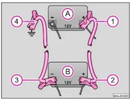
text_image
4 A 12V 1 3 B 12V 2 BA4-0K33HA - Discharged battery
B - Battery supplying current
Warning
Do not connect the cable to the negative terminal (-) of the discharged battery. This can produce sparks when the engine is started which might ignite the gas flowing out of the battery.
Do not affix the cable end 4 to parts of the fuel and brake system.
Warning
■The non-insulated parts of the cable clamps must not touch one another on any account. In addition, the jump-start cable attached to the positive terminal of the battery must not come into contact with electrically conducting parts of the vehicle - risk of short circuit!
■Route the jump-start cables so that they cannot come into contact with rotating parts in the engine compartment.
■Do not bend over the batteries - risk of acid burns!
■Keep sources of ignition (naked flames, burning cigarettes etc.) well away from the battery - risk of explosion!
■Start the engine as described in the section „Starting engine“.
■If the engine does not start right away, do not crank the starter for more than 10 seconds and then wait about 30 seconds before making a further attempt.
■Once the engine is running, disconnect both cables in exactly the reverse order.
Tow-starting/towing

text_image
① ② BA4-0654HThe towing eyes are located at the rear right below the bumper and at the front - see arrow.
A tow rope or tow bar should be attached only to these towing eyes.
■Remove a ventilation grille before using the front towing eye. Ventilation grille is held in place with plastic spring catches in the area of the arrow. Ventilation grille can be removed by hand.
■Grasp the top part of the grille, press grille off in direction of arrow 1 and take out in direction of arrow 2.
■After using the towing eye, insert the ventilation grille into the guides and press on.
It is not recommended to tow-start the vehicle (despite observing the instructions which are given in the Owner's Manual) in view of the fact that severe engine damage may result in certain circumstances.
It is best to attempt to start the engine by using jump-starting cables - refer to page 177 of the Owner's Manual - or to call on the services of SERVICE Mobil.
General information
■The tow rope should be elastic so that there is no strain on either vehicle. It is best to use only plastic fibre ropes or ropes made of a similarly elastic material. It is important to ensure that no impermissible pulling forces and no sudden shock loads occur. If attempting to tow a car which is not on a paved road, there is always a risk of the parts of the car to which the tow rope is attached being subjected to excessive stress and damaged.
■Before attempting to start the engine by tow-starting the car, always use the battery of another vehicle as a jump-starting aid if possible - see page 177.
It is essential to pay attention to the following points when tow-starting and towing the car:
■Observe any legal regulations regarding towing another vehicle.
■Both drivers should be acquainted with the special features of towing a vehicle. Persons not familiar with towing a vehicle should not attempt to tow-start or tow a car.
■If a tow rope is used, the driver of the towing vehicle should engage the clutch particularly softly when moving off and shifting gears.
■The driver of the towed car should ensure that the tow rope is always taught.
■The ignition of the towed car should be switched on so that the steering wheel is not blocked and the turn signal lights, the windscreen wipers, horn, lights and other electrical components can be switched on.
■As the brake servo unit only operates when the engine is running, note that sufficiently greater force is required to depress the brake pedal when the engine is not running and the steering is also much more difficult to operate.
For technical reasons, it is not possible to tow-start a car fitted with an automatic gearbox.
In the event of a defect in the gearbox, your vehicle no longer contains lubricant, the car must be towed with the driving wheels lifted or on a special transporter or trailer.
DO-IT-YOURSELF
Additional points for the driver of the towed vehicle to note during tow-starting:
■Before starting to tow the car, engage 3rd or 4th gear, depress clutch pedal and hold. The ignition should be switched on.
■Once both vehicles are moving, release the clutch pedal.
■As soon as the engine has started, depress clutch pedal and take the car out of gear to avoid running into the towing vehicle.
If your car is fitted with a catalytic converter, the engine must not be started by towing the car over a distance of more than 50 m (150 ft) if the catalytic converter is warm otherwise uncombusted fuel may get into the catalytic converter and cause damage.
Pay attention to the following points if towing a car fitted with an automatic gearbox:
■ Move the shift lever into position „N“.
■The maximum towing speed is 50 km/h (30 mph).
■The maximum towing distance is 50 km (30 miles)!
■If the car has to be towed over a greater distance, the front wheels should be raised clear of the ground.
The gear oil pump does not operate when the engine is not running; consequently, the gearbox is not sufficiently lubricated when running at high speeds and over lengthy distances.
■If the car is towed by a tow truck, the front wheels should always be raised clear of the ground.
If the rear wheels are raised clear of the ground, the drive shafts will rotate in the opposite direction. As a result, the gears in the automatic gearbox will run at such high speeds that the gearbox could suffer severe damage within a short time.
Vehicle identification data
The vehicle identification number (chassis number)
is stamped in the rear cross panel of the engine compartment. It is visible through a window in the plenum chamber cover.
This number is also shown in the left corner of the windscreen.
The engine number
is stamped on the engine block.
Identification plate
is located in the front of the engine compartment at the left suspension strut dome.
Homologation plate\*
is located on the front lock panel.
Vehicles for certain countries are not provided with a homologation plate.

text_image
1 2 3 4 TM5KG11UOY8296212 AGR 1U52TX OCTAVIA COMBI GLX EAG 1026 GR 88KW AGR EOA 10Q 3BS 3AF 1KE 6FB 1AH 3FA 1N1 1NO 3BE 4UC 4FO 3NW 3OT 4XO 4AO 8LS JOL 7AA BGL 6YO 9AA 8RE 7OO 8AA BOH 8XO 4F1 B03 1GB 3L1 9PO Q1A 7XO 5WO 8WD 7AO 3GA QGO BA4-0984HVehicle data sticker
is located below the floor covering of the luggage compartment.
The sticker contains the following vehicle data:
1 - Vehicle identification number
2 - Vehicle model
3 - Engine output/Gearbox/ Engine code letters/Gearbox code letters Paint number/Interior equipment number
4 - Optional equipment number.
The vehicle data are also stated in the Service Schedule.
Sticker on fuel filler flap
A sticker is affixed to the inside of the fuel filler flap, and contains the following information:
- approved fuel specification
- tyre inflation pressures
- tyre sizes.
ALPHABETICAL INDEX
4x4 models, 123
A
ABS, 60, 122
Accessories, 159
- Changes and replacement of parts, 159
Accumulator, 146
Acoustic signals, 46
Adjustable steering wheel, 43
Adjusting,
- Seats, 19
- Seat belt height, 100
- Headlamp beam, 66
Air conditioning system, 75
Air outlet vents, 73, 76, 83
Airbag system, 56, 103
Airbag, 103
Alarm, 13
Anti-theft alarm system, 13
Armrest, 36
Ashtrays, 90
Automatic air conditioning, 79
Automatic gearbox, 39
Automatic vehicle wash systems, 130
Automatic wipe/wash, 71
B
Balancing wheels, 154
Battery - charging, 61
Battery - recharging, 149
Battery, 146
Beverage holder, 87
Beverages, 87
Bonnet, 135
- Opening, 135
- Closing, 135
Brake Assist, 121
Brake booster, 121
Brake fluid level, 144
Brake fluid, 61, 144
Brake fluid, 61, 144
Brake pad, 58
Brake system, 61, 120, 121, 122, 123, 144
Brakes, 61, 120, 121, 122, 123, 144
Breakdown assistance, 161
Bulbs, 60, 161, 170
C
Cavity protection, 134
CD changer, 31
Central locking, 8
- Opening a single door, 9
Cigarette lighter, 89
Climatronic, 79
Clock, 50
Cockpit, 5
Coming home, 67
Convenience operation, 10, 16, 86
Coolant level, 143
Coolant temperature, 48
Coolant, 48, 58, 142
Coolant, 48, 58, 142
Cooling, 142
Cruise control system, 68
D
Defrosting windows, 63, 73, 76
Diesel engines, 46
Diesel, 128
Digital clock, 50
Disc wheels, 133
- Steel wheels, 133
- Light-alloy wheels, 133
Door and window seals, 132
Door, 8
Driving abroad, 158
Driving economically and in an environmentally
Dust, noise and pollen filter, 152
E
EDL, 61, 122
Electric sliding/tilting roof, 85
Electrical power windows, 15
Electrically adjustable seats, 20
Engine - starting, 44
Engine - switching off, 46
Engine compartment, 135
Engine electronics, 57, 60
ALPHABETICAL INDEX
Engine oil, 138
- Specification, 138
Engine oil, 59, 118, 138
Engine oil, 59, 119, 138
EPC, 57, 60
ESP, 60, 64
Exterior mirror, 16
F
Fault display, 50
Fire extinguisher, 166
First-aid box, 161
Fog lights, 57, 63
Fog lights, 63
Four-wheel drive models, 123
Fresh air, 78
Friendly way, 118
Front airbag, 103
Front passenger airbag switch, 107
Fuel consumption, 119
Fuel reserve, 49, 58
Fuel, 49, 58, 65, 119, 128
Fuses, 167
H
Handbrake, 36
Hands-free system, 37
Hazard warning light system, 63
Hazard warning light system, 63
Head restraints, 18, 95
- Adjusting head restraints, 18, 95
- Adjusting height, 18, 95
Headlamp beam adjustment, 66
Headlight flasher, 5
Headlight flasher, 67
Headlights - masking over, 158
Heating, 72
Hydraulic oil, 141
CH
Child safety locks, 8
Child safety, 111
Child seat, 111
Chrome parts, 132
|
Identification data, 181
Ignition lock, 43
- Steering lock, 44
Immobiliser, 7, 61
Indicators, 48
Information display, 53
Instrument lighting, 62
Interior light, 87
Interior lights, 88
Interlock, 101
ISOFIX system, 116
Isofix, 116
J
Jump-starting, 177
K
Keys, 6
L
Lashing eyes, 29
Lights, 62
- Warning lights, 56
- Parking lights, 67
- Turn signal lights, 67
- Changing a bulb, 169
Loading area cover, 32
Loading area increased (Estate), 32
Locking the car, 8
Low beam, 62
Low beam, 62
Luggage compartment cover (Estate), 32
Luggage compartment cover, 26
Luggage compartment lights, 89
Luggage compartment, 11, 27
M
Manual shifting of gears, 38
Mobile phone, 37, 159
Mobile phones and two-way radio systems, 159
MSR, 123
Multifunction display (MFD), 50
Multifunction steering wheel, 70
Multifunction switch, 67
ALPHABETICAL INDEX
N
Navigation system, 55
Net partition, 33
Net, 30
Noise, dust and pollen filter, 152
Note holder, 91
0
Oil consumption, 119
On-board instruments, 48
P
Paint damage, 131
Parking light, 62
Parking light, 67
Parking ticket, 91
Pedals, 35
Pelvic belt, 101
Petrol engines, 45
Plastic and synthetic leather parts, 132
Polishing the car, 131
Power steering, 141
Preglow system (diesel), 43, 45, 57
Prewarming fuel, 129
R
Reading light, 88
Rear-view mirror, 16
Recirculated air mode, 73, 76
Refuelling the car, 65, 127
Remote control, 12
- Replacing the code, 13
Replacement
- Brake fluid, 145
- Parts, 159
- Wheel, 163
- Oil, 141
- Fuses, 167
Bulbs, 169
Rev counter, 48
Roof luggage rack system, 91
Roof luggage rack system, 91
Running in the car, 117
S
Safe securing system, 9
Safety net, 30
Safety, 93
Seat belt tensioners, 102
Seat belt tensioners, 102
Seat belts, 98
Seat belts, 98
Seat heaters, 65
Seat height, 19
Seats, 19, 25, 94
Securing wheels, 166
Service Display, 49
Service interval, extended, 138
Shift pattern, 38
Shifting gears, 38
Side airbag, 109
Signals, acoustic, 46
Snow chains, 157
Socket 12 V, 89
Spare wheel, 162
Spark plugs, 150
Spectacle case, 91
Spectacles, 91
Speedometer, 49
Speedometer, 49
- Counter for distance driven, 49
Spray for tyre repair, 162
Steering wheel, 5, 43, 70
Storage compartments, 10, 87
Sun visors, 86
Support of pelvic belt, 20
Switch, 62
Switching from high beam to low beam, 67
T
Taking care of your vehicle, 129
TCS, 60, 65
Technical changes, 160
Temperature display, 52
The first 1500 km, 117
Tool, 161
Top up with oil, 140
Towing a trailer, 124
Towing a vehicle, 178
Towing device, 124
ALPHABETICAL INDEX
Towing eyes, 178
Tow-starting the car, 178
Trailer, 124
Transporting children, - Child safety, 111
Turn signal lights, 56, 67
Two-way radio system, 159
Tyre repair kit, 162
Tyre repair, 162
Tyres, 153
U
Underbody protection, 134
V
Vehicle data sticker, 181
Ventilation, 72
V-ribbed belts, 150
W
Warning light „Airbag OFF“, 108
Warning lights, 56
Warning triangle, 161
Washing car by hand, 130
Washing car with water under pressure, 131
Washing the car, 130
Wax treatment, 131
Wheel securing bolts, 166
Wheels, 133, 153
Window heater, 63
Windows, 131
Windscreen washer system, 60, 71, 151
Windscreen wiper blades, 152
Windscreen wipers, 71, 151
Škoda Auto pursues a policy of constant product and model development. We trust that you will understand that changes to models in terms of shape, equipment and engineering, may be introduced at any time. It is therefore not possible for legal claims to be made based on the data, illustrations and descriptions contained in this Owner's Manual.
Reprint, reproduction or translation, either in whole or in part, is not permitted without the written consent from Škoda Auto.
Škoda Auto expressly reserves all rights relating to copyright laws.
We reserve the right to make changes to this document.
Published by ŠKODA AUTO a. s.
© ŠKODA AUTO a. s. 2004
SIMPLY CLEVER

text_image
SKODA Service Škoda Genuine Parts Škoda Genuine AccessoriesHow you can contribute to a cleaner environment
The fuel consumption of your Škoda – and thus the level of pollutants contained in the exhaust – is also determined by how you drive.
The noise level and wear and tear are also influenced by how you personally handle your vehicle. This Owner's Manual tells you how to drive your Škoda to achieve the minimum impact on the environment, and how to save money at the same time. Look up „Environment“ in the Index to find out more.
Please also refer to all the texts identified with a ✿ in this Owner's Manual.
Make your contribution - for the sake of the environment.
Návod k obsluze
Octavia anglicky 10.04
S63.5610.32.20
1U0 012 003 GR
www.skoda-auto.com