VCV Random - Uncategorized NANO Modules - Free user manual and instructions
Find the device manual for free VCV Random NANO Modules in PDF.

| Product Type | Eurorack Synthesizer Module |
| Brand | NANO Modules |
| Model | VCV Random |
| Module Width | 4 HP |
| Depth | 30 mm (approx.) |
| Weight | 50 g |
| Power Supply | +12V: 50 mA, -12V: 20 mA |
| Power Connector | 10-pin Eurorack ribbon cable |
| Main Functions | Random voltage generator, sample & hold, clock divider, burst generator |
| Inputs | Clock (3.5mm jack), Reset (3.5mm jack) |
| Outputs | Random CV (3.5mm jack), Gate (3.5mm jack) |
| Controls | Rate knob, Spread knob, Mode selector |
| Status LEDs | Gate output indicator, Clock input indicator |
| Construction | PCB with aluminum front panel |
| Mounting | Standard Eurorack rails with screws |
| Operating Temperature | 0°C to 50°C |
| Maintenance | Clean with dry cloth only; avoid liquids |
| Safety | Do not expose to moisture; disconnect power before installation |
| Spare Parts & Repairability | Contact NANO Modules support for repairs or parts |
| General Information | Designed in Spain; compact random voltage utility |
Frequently Asked Questions - VCV Random NANO Modules
User questions about VCV Random NANO Modules
0 question about this device. Answer the ones you know or ask your own.
Ask a new question about this device
Download the instructions for your Uncategorized in PDF format for free! Find your manual VCV Random - NANO Modules and take your electronic device back in hand. On this page are published all the documents necessary for the use of your device. VCV Random by NANO Modules.
USER MANUAL VCV Random NANO Modules
Thank you for choosing VCV RANDOM for your Eurorack System.
Powering up
- Turn off the power of your modular synthesizer.
- Double check the power cord polarity. If you plug the module backwards you might damage its electronic circuits.

natural_image
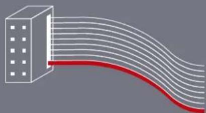
Diagram of a building with curved lines extending from it, no text or symbols presentIf you flip over your VCV RANDOM, you will find the "RED" mark at the PCB power connector, which must match the colored line on the ribbon cable.
- Once you have checked all the connections, you can turn on your modular system.
- If you notice any anomalies, turn your system off right away and check again your connections.
Description
VCV Random is the hardware version of a well-known classic from the VCV Rack fundamental library. A random CV generator with 4 types of randomness and a triggerable sample-and-hold function.
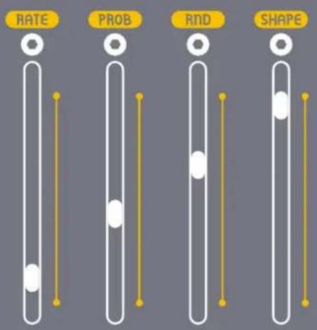
Its sliders allow you to set the internal clock tempo (RATE), shape the probability of triggering (PROB), blend old with new values (RND) and set the shape of all four random outputs (SHAPE).

flowchart
graph TD
    A["In"] --> B["RANDOM SOURCE"]
    C["TRIG"] --> D["INT. CLOCK rate"]
    B --> E["CROSSFADE rnd"]
    D --> F["PROBABILITY"]
    E --> G["S & H sample"]
    F --> G
    G --> H["STEP shape"]
    G --> I["LIN shape"]
    G --> J["EXP shape"]
    G --> K["SMOOTH shape"]
    H --> L["TRIG"]
    I --> L
    J --> L
    K --> L
Fig.1 Overview of the module functions
Layout
This image will clarify the function of each of the elements of the module.

flowchart
graph TD
    A["IN Input"] --> B["Trigger Input"]
    B --> C["CV Inputs"]
    C --> D["CV Attenuverters"]
    D --> E["RND"]
    E --> F["Rate"]
    F --> G["Randomness Sliders"]

    H["TRIGIN"] --> I["OFFSET"]
    I --> J["SOFT"]
    J --> K["SMITHSTEPLINEKP"]

    L["TRIG"] --> M["OFFSET"]
    M --> N["SMITHSTEPLINEKP"]

    O["ON/O"] --> P["Rate"]
    P --> Q["PROB"]
    Q --> R["RND"]
    R --> S["SHAPE"]

    T["ON/O"] --> U["Rate"]
    U --> V["PROB"]
    V --> W["RND"]
    W --> X["SHAPE"]

    Y["ON/O"] --> Z["Rate"]
    Z --> AA["PROB"]
    AA --> AB["RND"]
    AB --> AC["SHAPE"]

    AD["ON/O"] --> AE["Rate"]
    AE --> AF["PROB"]
    AF --> AG["RND"]
    AG --> AH["SHAPE"]

    AI["ON/O"] --> AJ["Rate"]
    AJ --> AK["PROB"]
    AK --> AL["RND"]
    AL --> AM["SHAPE"]

    AN["ON/O"] --> AO["Rate"]
    AO --> AP["PROB"]
    AP --> AQ["RND"]
    AQ --> AR["SHAPE"]

    AS["ON/O"] --> AT["Rate"]
    AT --> AU["PROB"]
    AU --> AV["RND"]
    AV --> AW["SHAPE"]

    AX["ON/O"] --> AY["Rate"]
    AY --> AZ["PROB"]
    AZ --> BA["RND"]
    BA --> BB["SHAPE"]

    BC["ON/O"] --> BD["Rate"]
    BD --> BE["PROB"]
    BE --> BF["RND"]
    BF --> BG["SHAPE"]

    CA["ON/O"] --> CB["Rate"]
    CB --> CC["PROB"]
    CC --> CD["RND"]
    CD --> CE["SHAPE"]

    CF["ON/O"] --> CG["Rate"]
    CG --> CH["PROB"]
    CH --> CI["RND"]
    CI --> CJ["SHAPE"]

    CK["ON/O"] --> CL["Rate"]
    CL --> CD
    CD --> CD
    CD --> CE
    CE --> CL
Controls
- Randomness Sliders
RATE
Adjusts the internal clock's tempo. Upon each clock trigger, the RATE slider light blinks, and there is a chance for the internal random source to generate a new value.
PROB
Sets the probability of generating a new random value each clock cycle. If one is generated, the PROB slider light blinks and a pulse is emitted from the TRIG output.
RND
Blends the previous value with a random one, in a proportion determined by the RND slider. It affects the range of the voltage output.
SHAPE
Controls the transition shape to the new random value across all four outputs.
text_image
RATE PROB RND SHAPEFig.2 Detail of the randomness sliders
Controls
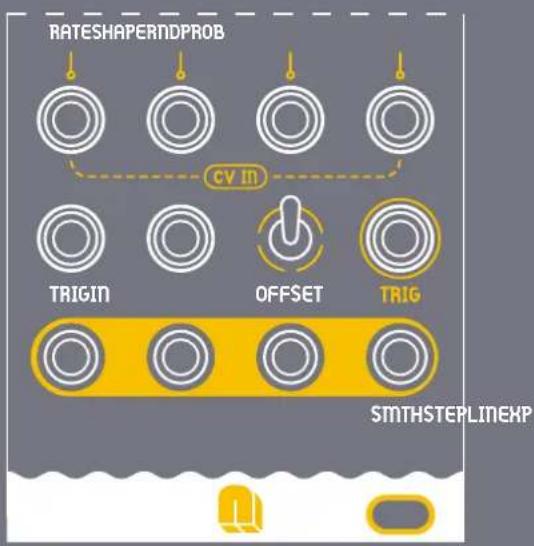
• CV Attenuverters
These knobs control how much and in what way an external signal affects the randomness parameters.
In the center position (0), the signal does not affect the parameter.
If you turn it to the right, it attenuates (turns down the strength) the signal.
If you turn it to the left, it inverts the signal, making things that were going up, go down instead, and vice versa.
- Offset Switch
Unipolar (0V to 10V).
With the switch facing up, the signal starts at 0 volts and can go up to 10 volts.
This setting is great for controlling things that have a clear starting and ending point, like the brightness of a light.
Bipolar (-5V to 5V).
With the switch facing down, the signal can move both ways: it starts in the middle (at 0), can go down to -5 volts, or up to 5 volts.
This is useful for parameters that need to move in two directions, like pitch, which can go higher or lower from a central note.

text_image
RATESHAPERNDPROBFig.6 Detail of module attenuverters

Fig.7 Detail of OFFSET switch
Inputs & Outputs
- Inputs
/CV INPUTS
Modulate the Rate, Probability, Random Range, and Shape with an external voltage. The applied signal is summed to each slider position.
/TRIG IN
If the TRIG input is patched, the RATE slider is ignored, and the clock is only triggered when an external trigger is received. The PROB slider is used to filter this trigger by some probability.
/IN
If the IN input is patched, this external voltage is used instead of a random voltage upon each trigger. The RND slider has no effect.
- Outputs
/TRIG OUT
if a new value is generated, a pulse is emitted from the TRIG output.
flowchart
graph TD
    A["Rateshaper"] --> B["PROB"]
    B --> C["CV IN"]
    C --> D["TRIGIN"]
    C --> E["OFFSET"]
    C --> F["TRIG"]
    D --> G["SMTHSTEPLINEXP"]
    E --> G
    F --> G
Fig.8 Inputs & Outputs Close-up View
- Outputs
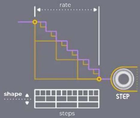
/STEP
The STEP output jumps to the new value in one step at 0% SHAPE, and divides the transition into 16 steps at 100% SHAPE.
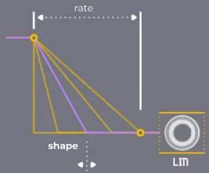
/LIN
The LIN output immediately reaches the new value at 0% SHAPE, and takes the whole clock cycle to do so at 100% SHAPE, staying constant in between.
/EXP
The EXP output shifts exponentially, becoming linear at 100% SHAPE, with its pace adjusted by the SHAPE slider.
/SMTH
The SMTH output transitions smoothly, with the speed controlled by the SHAPE setting, holding at the target until the cycle ends.
flowchart
graph TD
    A["step"] --> B["rate"]
    B --> C["STEP"]
    style A fill:#f9f,stroke:#333
    style C fill:#bbf,stroke:#333
    subgraph "shape"
        D["steps"]
    end
    style D fill:#fff,stroke:#000
    style E fill:#fff,stroke:#000
    style F fill:#fff,stroke:#000
    style G fill:#fff,stroke:#000
    style H fill:#fff,stroke:#000
    style I fill:#fff,stroke:#000
    style J fill:#fff,stroke:#000
    style K fill:#fff,stroke:#000
    style L fill:#fff,stroke:#000
    style M fill:#fff,stroke:#000
    style N fill:#fff,stroke:#000
    style O fill:#fff,stroke:#000
    style P fill:#fff,stroke:#000
    style Q fill:#fff,stroke:#000
    style R fill:#fff,stroke:#000
    style S fill:#fff,stroke:#000
    style T fill:#fff,stroke:#000
    style U fill:#fff,stroke:#000
    style V fill:#fff,stroke:#000
    style W fill:#fff,stroke:#000
    style X fill:#fff,stroke:#000
    style Y fill:#fff,stroke:#000
    style Z fill:#fff,stroke:#000
text_image
rate shape Lm
text_image
rate shape EXP
text_image
rate shape SMTHCompliance
This device complies to the EU guidelines and is manufactured RoHS conforming without use of led, mercury, cadmium and chrome. Nevertheless, this device is special waste and disposal in household waste is not recommended.
This device meets the requirements of the following standards and directives:
• EMC: 2014/30/EU
• EN 55032. Electromagnetic compatibility of multimedia equipment.
- EN 55103-2. Electromagnetic compatibility - Product family standard for audio, video, audio-visual and entertainment lighting control apparatus for professional use.
• EN 61000-3-2. Limits for harmonic current emissions.
- EN 61000-3-3. Limitation of voltage changes, voltage fluctuations and flicker in public low-voltage supply systems.
- EN 62311. Assessment of electronic and electrical equipment related to human exposure restrictions for electromagnetic fields.
• RoHS2: 2011/65/EU
• WEEE: 2012/19/EU


Guarantee
This product is covered by 2 years of guarantee on purchased goods, which begins when you receive your package.
• This guarantee covers
Any defect in the manufacturing of this product. Replacement or repair, as decided by NANO Modules.
• This guarantee does not cover
Any damage or malfunction caused by incorrect use, such as, but not limited to:
- Power cables connected backwards.
- Excessive voltage levels.
- Unauthorized mods.
- Exposure to extreme temperature or moisture levels.
Please contact our customer service - jorge@nanomodul.es - for a return authorization before sending the module. The cost of sending a module back for servicing is paid for by the customer.
Technical Specifications
Dimensions 10HP 50x128,5mm
Current 63 mA +12V / 11 mA -12V / 0 mA +5V
Input & Output Signals ±10V
Impedance Input 10k - Output 10k
Materials PCB and Panel - FR4 1,6mm
Depth 40mm - Skiff friendly
Modules are designed and assembled in València.
Contact
Bravo!
You have learned the basic fundamentals of your VCV RANDOM Module.
If you have any doubts, please feel free to contact us. nanomodul.es/contact