
SNEV001 - Umweltsensor CyberPower - Kostenlose Bedienungsanleitung
Finden Sie kostenlos die Bedienungsanleitung des Geräts SNEV001 CyberPower als PDF.


| Produkttyp | Umweltsensor |
| Modell | SNEV001 |
| Marke | CyberPower |
| Abmessungen | 67 x 53 x 29 mm (2,63 x 2,08 x 1,14 Zoll) |
| Gewicht | 48 g (1,69 oz) |
| Eingangsspannung | 7 V - 28 V |
| Temperaturmessbereich | -10 °C bis 70 °C (14 °F bis 158 °F) |
| Temperaturgenauigkeit | ±0,5 °C (±0,9 °F) |
| Luftfeuchtigkeitsmessbereich | 10 % bis 90 % relative Feuchte |
| Luftfeuchtigkeitsgenauigkeit | ±2 % |
| Anschluss | RJ45 (Daten-IN und Daten-OUT) |
| Daisy-Chain | Bis zu 8 Sensoren |
| Trockenkontakte | 4 Eingänge |
| Status-LED | Ja |
| Montage | Klettband oder Schraubbefestigung |
| Zertifizierungen | FCC Klasse B, CE, EAC |
| Garantie | 3 Jahre beschränkt |
| Lieferumfang | Sensor, Klettband, Bedienungsanleitung, Flachkopfschraube (M3x20) mit Dübel, CAT5 RJ45-Kabel (3 m) |
| Maximale Kabellänge | 15 m (50 Fuß) zwischen Sensor und RMCARD/PDU |
| Weitere Funktionen | Fernüberwachung, automatische Benachrichtigungen per E-Mail/SMS/SNMP, Namens- und Standortanzeige |
Häufig gestellte Fragen - SNEV001 CyberPower
Benutzerfragen zu SNEV001 CyberPower
0 Frage zu diesem Gerät. Beantworten Sie die, die Sie kennen, oder stellen Sie Ihre eigene.
Eine neue Frage zu diesem Gerät stellen
Laden Sie die Anleitung für Ihr Umweltsensor kostenlos im PDF-Format! Finden Sie Ihr Handbuch SNEV001 - CyberPower und nehmen Sie Ihr elektronisches Gerät wieder in die Hand. Auf dieser Seite sind alle Dokumente veröffentlicht, die für die Verwendung Ihres Geräts notwendig sind. SNEV001 von der Marke CyberPower.
BEDIENUNGSANLEITUNG SNEV001 CyberPower
CyberPower
YOUR ULTIMATE ALLY IN POWER
ENVIRONMENTAL SENSOR
SNEV001
USER MANUAL


Cyber Power Systems (USA), Inc.
4241 12th Avenue East, Suite 400 | Shakopee, MN 55379
CyberPowerSystems.com
OVERVIEW
The CyberPower environmental sensor (SNEV001) along with selected Remote Management Cards (RMCARDXXX) or most Switched and Monitored PDUs enables users to monitor the temperature and humidity of a server closet and/or data center remotely. With CyberPower's PowerPanel® Business software, users can establish thresholds that will automatically notify users when an event has occurred via email, SMS and SNMP traps. Additionally, the SNEV001 provides four input dry contacts that enable users to monitor the status of connected devices, such as door switch sensors.
FEATURES
• Real time environment monitoring
- Remote management and configuration of the sensor via Web Browsers or NMS
• Automatic events notification via email, SMS and SNMP traps
• Four input dry contacts application interface provided
- Displays the name and location of the sensor and connected devices
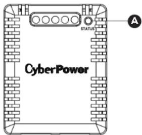
A. Status LED
B. Input Dry Contact 1-4
C. Common Connection
D. RJ45 Port
Connect to RMCARD/PDU or previous on-line SNEV001
E. RJ45 Port
Connect to next SNEV001
Input Dry Contact Application
Do not input signals that carry voltage into the input dry contacts. The input dry contacts only allow for open/short circuit.

External Sensor 1/2/3/4
PACKAGE CONTENTS
- SNEV001
- Hook and loop tape
- User Manual
- Flat Head Screw (M3x20) with plastic nylon anchors
- CAT5 RJ45 Ethernet Cable (10 ft. / 3.0 m)
SPECIFICATIONS
Model Number: SNEV001
Input Voltage: 7V - 28V
Temperature:
14-158°F with accuracy +/- 0.9°F
-10-70°C with accuracy +/- 0.5°C
Humidity: 10-90 RH with accuracy +/- 2%
Connection Port: RJ45 Port
Daisy Chain x 8 maximum
Input Dry Contact: 4
Dimensions:
2.63 × 2.08 × 1.14 in.
67 × 53 × 29 mm
Weight:
1.69 oz / 48 g
Safety Approvals:
FCC Class B, CE, EAC
Warranty:
3-Year Limited
A/WARNING: This product can expose you to chemicals including bisphenol A (BPA) and styrene (ABS), which is known to the State of California to cause reproductive harm and cancer. For more information, go to www.P65Warnings.ca.gov.
INSTALLATION GUIDE
Method 1: Hook and Loop Tape Mounting
Step 1. Clean the surface of the area where the sensor will be installed. Apply one side of the hook and loop tape to the bottom of the sensor and the other side to the sensor location.
Step 2. Attach the sensor on the surface and hold for about 5 seconds to ensure cohesion.
NOTE: Once the sensor is installed, you will want to leave it in place to ensure the the hook and loop tape maintains its adhesiveness.
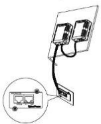
Step 3. To connect the sensor with RMCARD/PDU, use the attached RJ45 Ethernet Cable. Plug one end into the RMCARD/PDU. Furthermore, if daisy chain function is needed, plug one end into the RJ45 Port (DATA OUT) and the other end into the RJ45 Port (DATA IN) of another sensor.
NOTE: If the distance of RMCARD/PDU and the sensor is longer than 10 feet/3.05 m, use a standard RJ45 Ethernet Cable as needed (max 50 feet/15 m).
WARNING: Maximum daisy chain; 8 pcs
![graph TD A["Input Panel"] --> B{Switch} B --> C["Device 1"] C --> D["Device 2"] D --> E["Device 3"] E --> F["Device 4"] F --> G["Device 5"] G --> H["Output Panel"]](/content/2026/05/911718/images/f710cd51ec2e853343c6b71ee240908c81d146da8090cef80c030777e8c5b1da.jpg)
Method 2: Fixed Mounting
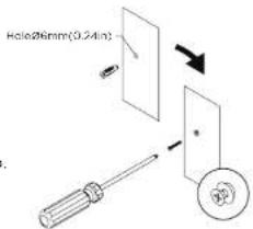
Step 1. Drill a hole that is compatible with the anchor and insert the included anchor.
Step 2. Insert and tighten the screw into the anchor. Leave enough of the screw exposed for the sensor to be mounted to.
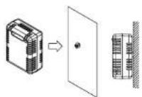
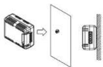
Step 3. Hang the sensor horizontally or vertically.
Step 4. To connect the sensor with RMCARD/PDU, use the attached RJ45 Ethernet Cable. Plug one end into the RJ45 Port (DATA IN) and the other end into the RMCARD/PDU. Furthermore, if daisy chain function is needed, plug one end into the RJ45 Port (DATA OUT) and the other end into the RJ45 Port (DATA IN) of another sensor.
For further configuration information, please refer to the RMCARD/PDU user's manual.
FOR MORE INFORMATION
Visit CyberPowerSystems.com for more information regarding:
• Product information and certifications
- Product warranty
• Connected equipment guarantee

CONFORMANCE APPROVALS
Operation is subject to the following two conditions: (1) the device may not cause harmful interference, and (2) this device must accept any interference resolved, including interference that may cause undesired operation.
This equipment has been tested and found to comply with the limits for a Class B digital device, pursuant to Part 15 of the FCC Rules. These limits are designed to provide reasonable protection against
harmful interference in a residential installation. This equipment generates, less, and can initiate radio frequency energy and if not installed and used in accordance with the instructions, may cause harmful interference to radio communications. However, there is no guarantee that interference will not occur in a particular installation. If the equipment does cause harmful interference to radio or television reception, which can be determined by turning the equipment off and on, the user is encouraged to try to correct the interference by one or more of the following measures:
TROUBLESHOOTING
| Problem Solution | |
| The RMCARD/PDU is not able to acquire environment sensor's information | Check the LED.When the connection is ok, the LED should always be on; otherwise, ensure the RJ45 Ethernet cable is correctly connected to the RMCARD/PDU and sensor.Note: Do not use a crossover cable which is for Tx/Rx. |
| The Input Dry Contact does not function correctly | Ensure the Input Dry Contact wires are correctly connected and make sure the open/short circuit setting of the connected devices is the same as the setting on the Web Interface. |

DISPOSAL
The Waste Electrical and Electronic Equipment (WEEE) Directive aims to contribute to sustainable production and consumption by contributing to the efficient use of resources and the retrieval of secondary raw materials through re-use, recycling and other forms of recovery. The symbol on this product and/or its packaging indicates that the product must be disposed of separately from ordinary household wastes at its end or life. Contact your related WEEE management authority, local office, or your household waste disposal service about information on the recycling drop off site.
TECHNICAL SUPPORT
Visit: CyberPowerSystems.com/support
Toll-Free: 1-877-297-6937
© 2024 Cyber Power Systems (USA), Inc. All rights reserved. All other trademarks are the property of their respective owners.
• Reorient or relocate the receiving antenna.
• Потехия: «Из separated» ветжете, «Веярения» иа пасажи. • Спектал: «Из separated» ветжете, «Веярения» иа пасажи.
that to which the receiver is connected.
• Consult the dealer or an experienced radio/TV technician for help
WARNING: Changes or modifications not expressly approved by the party responsible for compliance could void the user's authority to operate the equipment.


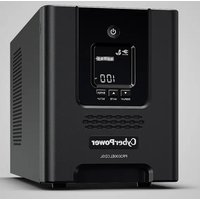
Marke : CyberPower
Modell : SNEV001
Kategorie : Umweltsensor