
Modulus Subwoofer - Subwoofer INFINITY - Kostenlose Bedienungsanleitung
Finden Sie kostenlos die Bedienungsanleitung des Geräts Modulus Subwoofer INFINITY als PDF.


| Produkttyp | Subwoofer (selbstständiges System) |
| Marke | Infinity |
| Modell | Modulus Subwoofer |
| Verstärkerleistung | 250 Watt (servogesteuert) |
| Stromversorgung | 100–240 V AC, 50/60 Hz (umschaltbar) |
| Sicherungswerte | 6 A träge (120 V/100 V), 3 A träge (220 V/240 V) |
| Frequenzweiche (Crossover) | Variabel von 45 Hz bis 180 Hz |
| Phasenregelung | 0° bis 180° kontinuierlich einstellbar |
| Tiefpassfilter (Low Cut) | 22 Hz oder 35 Hz (umschaltbar) |
| Hochpassfilter (Satelliten) | Passiv, 6 dB/Oktave bei 140 Hz (über ECU einstellbar) |
| Eingangsimpedanz | Anpassbar über DIP-Schalter (8 kΩ bis 1 MΩ) |
| Anschlusskabel | 7,6 m (25 ft) mit DIN-Steckern |
| Isolationsfüße | 4 schwarze Metallfüße mit Kunststoffkappen |
| Gehäuseoberfläche | Hochglänzendes Polyesterharz, kratzfest |
| Reinigung | Mit fusselfreiem Tuch und ammoniakfreiem Fensterreiniger |
| Standby-Anzeige | Rote LED hinter dem Gitter |
| Zubehör | Elektronische Steuereinheit (ECU), Silikonkleber, Bedienungsanleitung |
| Garantie | 1 Jahr auf Elektronik, 5 Jahre auf Lautsprecher (nur USA) |
Häufig gestellte Fragen - Modulus Subwoofer INFINITY
Benutzerfragen zu Modulus Subwoofer INFINITY
0 Frage zu diesem Gerät. Beantworten Sie die, die Sie kennen, oder stellen Sie Ihre eigene.
Eine neue Frage zu diesem Gerät stellen
Laden Sie die Anleitung für Ihr Subwoofer kostenlos im PDF-Format! Finden Sie Ihr Handbuch Modulus Subwoofer - INFINITY und nehmen Sie Ihr elektronisches Gerät wieder in die Hand. Auf dieser Seite sind alle Dokumente veröffentlicht, die für die Verwendung Ihres Geräts notwendig sind. Modulus Subwoofer von der Marke INFINITY.
BEDIENUNGSANLEITUNG Modulus Subwoofer INFINITY
modulus ^TM subwoofer ^TM
OWNER'S MANUAL

We at Infinity Systems, Inc. would like to take this opportunity to thank you for choosing the Modulus Subwoofer and commend you on your choice. The Modulus Subwoofer is a fully self-contained, 250 watt, servo-controlled subwoofer system able to achieve levels of performance that are unrivaled by similar systems. In order to bring out the best from your Modulus Subwoofer, it is important that you read through this manual before connecting and operating your subwoofer.
If any of the instructions in this manual are not clear or if you have any additional questions about installing or using your Modulus Subwoofer, you should contact your dealer or Infinity Systems for clarification.
UNPACKING THE SUBWOOFER
As you have undoubtedly noted, the subwoofer is extremely heavy, so please use caution when unpacking and handling it. Help from a second person is recommended when removing the subwoofer from its shipping carton.
The subwoofer cabinet is finished in a baked polyester resin that is durable and resistant to scratching and marring. However, the finish can be damaged if improperly handled. Care of the subwoofer cabinet is contained in a special section later in this manual.
If the subwoofer, or any of its associated parts was damaged in transit, contact your dealer, or carrier immediately.
The contents of the subwoofer carton should be checked to ensure that the following items are included:
- Subwoofer
- Electronic Control Unit (ECU)
- Four (4) black metal isolation feet
- Four (4) black plastic isolation feet covers
- One (1) packet of silicone adhesive
- One (1) 25 foot cable with DIN connectors at each end.
The subwoofer packing materials should be saved in case the subwoofer needs to be repackaged for reshipment at a later date.
As a minimum, save the packaging materials until you are sure your subwoofer is not damaged and is operating properly.
THE SUBWOOFER
The subwoofer includes the speaker, the power amplifier, and the input panel. The power amplifier is the black aluminum structure located on the right-front corner of the enclosure. The input panel is located on the bottom of the enclosure and the speaker is located behind the enclosure grille. Also located behind the grille, in the lower-right corner, is a red LED to indicate when the subwoofer input panel POWER switch is set to ON. This red LED indicates that the subwoofer is in the standby mode and ready to play.
Subwoofer Input Panel
The subwoofer input panel (figure 1), located on the bottom of the subwoofer, contains the controls and connectors required to make your subwoofer work with your system.
INPUT connector - is a DIN connector that is used to connect the subwoofer to the ECU.
POWER switch – turns the A.C. power on and off.
A.C. VOLTAGE SELECTOR - sets the subwoofer's power supply to conform with the A.C. line voltage at the user's location. The subwoofer is normally shipped with this switch set to 110 volts.
A.C. Line Cord – connects the A.C. power from the wall outlet to the subwoofer.
Power ON LED – lights when the POWER is set to ON.
ELECTRONIC CONTROL UNIT
The Electronic Control Unit (ECU) is an electronic device that is connected between your system preamplifier and the subwoofer. The ECU controls the subwoofer allowing the owner to make adjustments for optimum output regardless of the placement of the subwoofer.
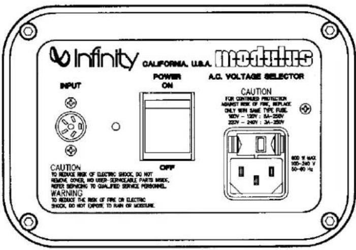
Figure 1. Subwoofer Input Panel
ECU Front Panel
The ECU front panel (figure 2) contains the controls and switches for crossover, phase, level and power to your subwoofer.
CROSSOVER control – sets the upper limit of the subwoofer frequency response. The upper limit is where the subwoofer begins to roll off to meet the low frequency output of your satellite speakers.
PHASE control – used to optimize the blend of the subwoofer with the satellites when the subwoofer cannot be placed in the best room location due to room layout or space. The phase control is variable from 0 to 180°. The control is normally set fully counterclockwise (0), but can be set anywhere within its rotation.
LEVEL control – sets the subwoofer volume.
LOW CUT selector – rolls off the response of the subwoofer at either 22Hz, or 35Hz. The normal setting is 35Hz. However, if a particular recording does not have rumble, or if the volume of the overall music being played is not excessively loud, then 22Hz can be used.
POWER switch – turns the A.C. power to the ECU on and off and activates the subwoofer.
Power ON LED - lights when power is applied to the ECU.
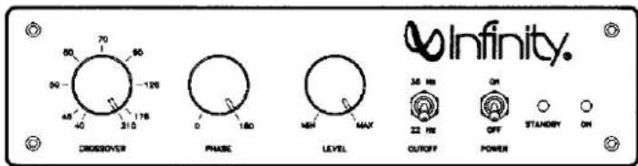
Figure 2. ECU Front Panel
ECU Input/Output Panel
The ECU input/output panel (figure 3) contains the switches and jacks that allows you to connect the ECU to your system and set up the voltage and high pass circuits.
HIGH PASS FREQUENCY DIP switches – used to select the ECU internal capacitor value to match the satellite amplifier input impedance. The capacitor value selected will create a 140Hz cutoff frequency at 6dB/octave. A complete discussion of the high pass circuit is contained in the ECU Initial Settings section of this manual.
OUTPUT connector – supplies subwoofer A.C. control voltage and the low frequency signal to the subwoofer power amplifier.
INPUT jacks (parallel pair) – one pair is used to connect the preamp output to the ECU. If you want to bypass the ECU's internal highpass crossover, the second pair can be used to connect the preamp output directly to the satellite speaker's amplifier.
HIGH PASS OUTPUT jacks (parallel pair) – one pair is used to connect the high pass output to the satellite speaker's amplifier. The second pair can be used to connect an RCA-type shunt resistor when required. This is discussed later in this manual.
A.C. VOLTAGE SELECTOR – sets the ECU's power supply to conform with the A.C. line voltage at the user's location. The ECU is normally shipped with this switch set to 110 volts.
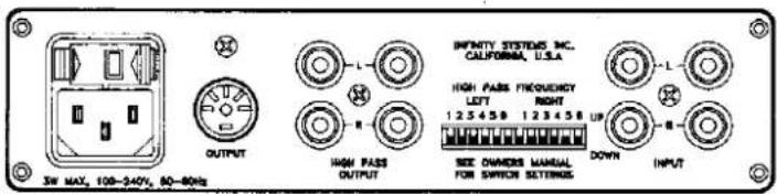
Figure 3. ECU Input/Output Panel
MAKING YOUR SUBWOOFER READY FOR USE Installing the Isolation Feet
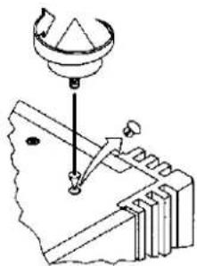
The four (4) black-metal isolation feet must be installed on the bottom panel of the enclosure. To install the isolation feet:
- Place the subwoofer on a soft, clean, scratch-free surface with the bottom facing up.
- Remove the plugs (figure 4) in each of the isolation feet mounting holes.
- Screw one isolation foot in each of the pre-threaded holes. Make sure that the isolation feet are tight.
natural_image
Technical line drawing of a mechanical assembly with a component and base (no text or symbols)Figure 4. Isolation Feet Installation
Installing The Isolation Feet Covers
If the subwoofer is going to be placed on a hardwood or tile surface, we recommend that you install the plastic covers over the isolation feet. The covers will prevent the feet from scratching the floor surface.
The covers should be glued in place with a small dab of the supplied silicone adhesive.
Input Voltage Settings
CAUTION: Before making any connections between the subwoofer, ECU, and your audio system components, be sure that the power switches are off and the A.C. plugs are removed from the wall outlet.
The ECU and subwoofer are designed to operate from a variety of input voltage levels and frequencies. When the voltage is changed, the current rating of the input fuse may also change.
The ECU contains an internal fuse that offers protection at all of the voltage settings.
The subwoofer input fuse must be changed per the following list as the input voltage level is changed.
The voltages are set using the A.C. VOLTAGE SELECTOR on the ECU input/output panel and the A.C. VOLTAGE SELECTOR on the subwoofer input panel.
The following is a list of the available voltage settings and applicable fuse size (current rating) for each.
Voltage/Frequency
Fuse Size
| 120V/60Hz (US) | 6 amp slow-blow |
| 100V 50/60Hz | 6 amp slow-blow |
| 220V/50Hz | 3 amp slow-blow |
| 240V/50 Hz | 3 amp slow-blow |
Changing the ECU Input Voltage Setting
The ECU input voltage is selected by sliding the A.C. VOLTAGE SELEC-TOR switch to the desired voltage setting.
ECU Initial Setting
Be sure to make the ECU Initial Settings before making any connections to the ECU.
CROSSOVER - 100Hz
PHASE - Full counterclockwise
LEVEL - 12 o'clock (50%)
LOW CUT - 35Hz
HIGH PASS FREQUENCY – see below
The ECU contains a passive 6dB/octave high pass filter which rolls off low frequency energy to the satellites at 140Hz. This is required so the satellites do not overload due to excessive low frequency energy which could cause bottoming of the drivers and excessive distortion.
Since amplifiers have varying input impedances (ranging from 5K ohms (rare) to 100K ohms, or higher) it becomes necessary to select the correct value of capacitance in order to achieve the desired corner (crossover) point of 140Hz. The amplifier's input impedance plus the amount of capacitance in the circuit determines the actual crossover point. You may determine the input impedance of your satellite speaker power amplifier by referring to your owner's manual, or contacting the amplifier manufacturer.
As the impedance drops, the required capacitance has to increase in order to maintain the recommended 140Hz crossover frequency. If the various "dip switches" on the ECU are not properly set (for example, if too much capacitance is added), the satellites could receive too much low frequency energy because the crossover frequency will move down, and this can result in satellite woofer bottoming, distortion, the inability of the satellites to play loudly, or even excessive heaviness in the mid-bass because the satellites in combination with the subwoofer are producing more low frequency energy than what is ideal.
Too little capacitance will move the crossover point to a higher than optimum frequency causing the sound to become thin and lacking in middle bass timbre.
The chart is a recommended starting point. If you feel that you have the capacity to identify nuances in sonic balance, you can trim the crossover frequency by adding, or deleting capacitance (by changing switches) until the sonic balance blends uniformly with the subwoofer, your room and personal preference.
NOTE: The switches are closed in the down position. See figure 5 for a schematic of the switch operation.
| Input Impedance Range in Ohms | Switch 8 | Switch 5 | Switch 4 | Switch 3 | Switch 2 | Switch 1 | Shunt Resistor* |
| 8-12K | DOWN | DOWN | UP | DOWN | DOWN | DOWN | - |
| 12-18K | UP | UP | DOWN | DOWN | DOWN | DOWN | - |
| 16-24K | UP | UP | DOWN | UP | DOWN | DOWN | - |
| 25-40K | UP | UP | DOWN | UP | UP | DOWN | - |
| 40-60K | UP | UP | UP | UP | UP | DOWN | - |
| 70-80K | UP | UP | UP | UP | UP | DOWN | 200K |
| 80-120K | UP | UP | DOWN | UP | UP | UP | - |
| 120-200K | UP | UP | UP | UP | UP | DOWN | 68K |
| 200-500K | UP | UP | UP | UP | UP | DOWN | 56K |
| 500K-1 Meg | UP | UP | UP | UP | UP | DOWN | 51K |
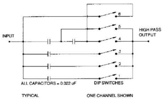
Figure 5. High Pass Filter Schematic Diagram
*NOTE: When plugged into the second pair of high pass outputs, the shunt resistor is in parallel with the input of the satellite amplifier. This lowers the effective impedance, allowing the use of the built-in capacitors in the ECU. If the amplifier you are using for your satellites requires the use of shunt resistors, as shown by the table above, call or write Infinity's Customer Service Department for assistance.
The 140Hz crossover frequency is not critical, and is given as a starting point. If, for example, your satellite speaker power amplifier has an input impedance of 200K, which requires a 68K shunt resistor to achieve the 140Hz crossover frequency, you could set the DIP switches for a 120K input impedance, and play the system without the 68K shunt resistor. This will result in a lower than 140Hz crossover frequency. If your satellite speakers show signs of distress (distortion) in the lower frequencies, exercise caution on how loudly you play the system until you can install the correct shunt resistor.
Changing the Subwoofer Input Voltage Setting and Fuse
- In the center of the A.C. VOLTAGE SELECTOR, loosen the fuse holder with a 1/4 turn counterclockwise.
- Using a pair of needle-nose pliers, insert the tips in the indentations, near the 110 and 200 marks, and slowly turn the switch to the desired setting.
- Remove the fuse and verify the size. NEVER INSTALL A FUSE WITH A HIGHER THAN RECOMMENDED RATING.
- Install the fuse by pushing in and turning clockwise until it locks in place.
Connecting the Subwoofer and ECU
CAUTION: Make sure that the voltage settings are the same for the ECU and Subwoofer.
-
On your audio system, locate the cable connected between the PREAMPLIFIER OUTPUT and AMPLIFIER INPUT.
-
Unplug the cable from the AMPLIFIER INPUT.
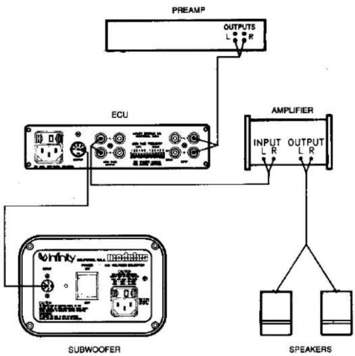
- Refer to figure 6 and connect the PREAMPLIFIER OUTPUT to one of the ECU INPUT pairs.
- Connect a cable between one of the ECU HIGH PASS OUTPUT pairs and your satellite speaker amplifier's INPUT.
- Connect the supplied 25 foot cable between the ECU OUTPUT connector and the subwoofer input panel INPUT connector.
flowchart
graph TD
    A["PREAMP"] --> B["OUTPUTS L R"]
    B --> C["ECU"]
    C --> D["INPUT L R"]
    C --> E["AMPLIFIER"]
    E --> F["SPEAKERS"]
    G["Subwoofer"] --> H["OUTPUT L R"]
    H --> I["SPEAKERS"]
Figure 6. System Interconnecting Diagram
Positioning the Subwoofer
The performance of the subwoofer with your satellite speakers is directly related to where it is placed in the listening room and how it is positioned with respect to the satellite speakers. The final position will be the result of patience and experimentation on your part. Testing for sonic balance and blending should always be done from your normal listening position using a wide range of source material.
Starting Position
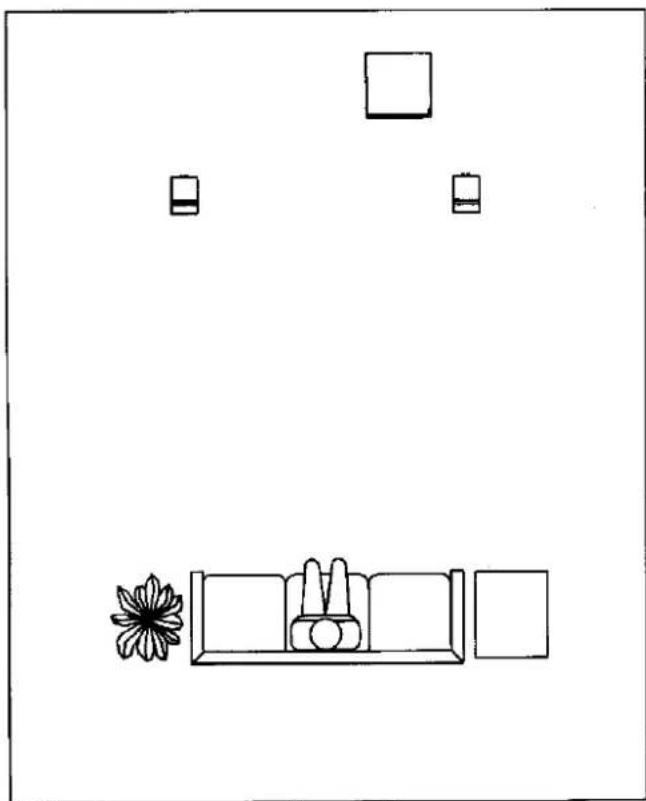
Begin your position experimentation by placing the subwoofer closer to the right satellite speaker with the rear of the subwoofer approximately six or seven inches from the rear wall, as shown in figure 7.
The initial position may turn out to be the most satisfactory. However, it is recommended that other locations be tried to obtain a smooth transition between the bass frequencies and the rest of the musical range. Figure 8 shows how bass response is affected by the subwoofer's position with respect to the wall(s). If the bass response is lean, try locating the subwoofer closer to a wall. If the bass is too heavy, the subwoofer should be moved away from the wall and placed near the center of the two satellite speakers. It is acceptable to place the subwoofer anywhere it looks and sounds best.
natural_image
Simple line drawing of a living room with a sofa, coffee table, and wall-mounted boxes (no text or symbols)Figure 7. Typical Starting Position Layout
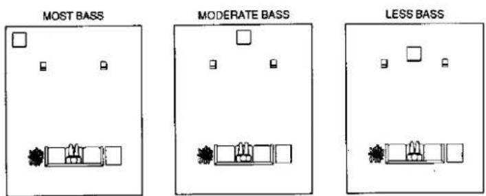
Figure 8. Bass Response With Relation To Wall(s)
OPERATING THE SUBWOOFER
Power Up
- Plug all components into an A.C. outlet.
- On the subwoofer input panel, set the POWER switch to ON. The power LED on the input panel will display a RED light. The red LED behind the grille indicates that the subwoofer is on standby.
- Turn on the power to the audio components.
- Set the ECU POWER switch to ON. The ECU activates the subwoofer and turns off the red LED behind the grille.
Listening to Your System
-
Turn the VOLUME control on your preamplifier to a comfortable listening level and begin playing a record, CD, or cassette that is rich in bass information.
-
Experiment with the controls on the ECU until you are pleased with the sound. The bass should enhance but not overpower the rest of the music.
- Experiment with the placement of the subwoofer. Minor position adjustments may produce results that are even more pleasing.
The 0 to 180° phase control located on the front panel of the ECU should be rotated to optimize the blend of the subwoofer and satellites. There will be a position within the full rotation of this control which will yield the best results. As you rotate the control listen for the following:
- Maximum bass output
- Greater low frequency definition
- A seamless transition between the subwoofer and the satellites.
You may experience all three sonic characteristics or only one or two. The phase control may be set anywhere within its rotation for optimum performance.
Impact of Tone Control on Your System
The tone controls on your audio components should be used with the utmost discretion. Excessive boost can demand hundreds of watts in the bass region. In the flat position or with the tone controls switched out of your system, as little as 10 watts can produce impressive and realistic listening levels. The remaining power amplifier capacity is in reserve for power peaks on sharp transients and powerful crescendos. With the flexibility of the ECU, you should be able to leave the bass control of your preamp at the flat position.
CARE OF THE ENCLOSURE
The enclosure of your subwoofer is finished with a durable, high-gloss, scratch-resistant polyester resin. The finish should be kept clean by occasionally dusting with a lint-free cotton cloth. Fingerprints and other minor blemishes may be removed with a lint-free cloth dampened with ammonia-free window cleaner. Do not use abrasive or chemical cleaners.
The grille may be cleaned by gently vacuuming with a furniture brush attachment.
IN CASE OF TROUBLE
If the subwoofer sounds distorted, stops playing, or otherwise seems to be malfunctioning, first determine if the problem is in the subwoofer, wiring, or other audio components. If the problem also affects the satellite speakers, the cause is most likely in your electronics. If it is only noticed in the subwoofer, make sure that all connecting cables are correct and in proper working condition. Make sure the subwoofer and ECU are plugged in and turned on. Check the subwoofer A.C. fuse. If everything seems to be in good working order and the subwoofer still malfunctions, DO NOT ATTEMPT ANY REPAIRS! Contact your dealer for the nearest authorized Infinity Service Center.
If you do not have a service center near you, contact:
Infinity's Customer Service
(818) 407-0228
or write:
Infinity Customer Service
9409 Owensmouth Avenue
Chatsworth, CA, 91311 (USA).
DO NOT SHIP YOUR SUBWOOFER OR ECU FOR SERVICE WITHOUT PRIOR AUTHORIZATION.
LIMITED WARRANTY
Who is protected by the warranty?
Your Infinity Warranty protects the original retail purchaser and all subsequent owners, during the stated warranty period, from any failure as a result of an original manufacturing defect so long as: (1) your Infinity product was purchased within the fifty United States, or purchased by military personnel from an authorized military outlet and (2) the original dated bill of sale is presented whenever service is required during the warranty period. This warranty does not apply to products purchased elsewhere; other purchasers should contact their local Infinity distributor for warranty information.
How long Is the warranty period?
| Warranty Period | ||
| Product Type | Labor | Parts |
| Electronic Products | 1 year | 1 year |
| Speaker Systems | 5 years | 5 years |
What does the Infinity Warranty cover?
Except as specified below, the Infinity Warranty covers all defects in original materials and workmanship. The following are not covered: Damage caused by accident, misuse, abuse, neglect, product modification; damage occurring during shipment; damage caused by failure to follow instructions in your owner's manual, including failure to perform recommended periodic or routine maintenance; damage resulting from repairs by someone not authorized by Infinity; claims based upon any misrepresentations by the seller; and any Infinity product on which the serial number has been altered, defaced or removed.
Who pays for what?
During the period that both parts and labor are covered by this warranty, Infinity will pay all of the labor and material expenses to repair a warrantable defect; during the period that parts ONLY are covered by this warranty, Infinity will pay for all materials to correct a warranted defect, but you must pay for the labor charges.
How can warranty service be obtained?
In the event that your Infinity product requires service, you should first contact the Infinity dealer from whom the product was purchased or if this is not practical, contact us at Infinity (Attn: Customer Service) at 9409 Owensmouth Avenue, Chatsworth, CA 91311 (818) 709-9400. We may direct you to an authorized service center for Infinity products or ask you to send your unit to us for repair. In either case you will have to present your original dated bill of sale to establish warranty coverage. Do not send your product to us without prior authorization.
You are responsible for transporting your product for repair and for payment of all shipping charges. However, Infinity will pay the return shipping charges if the repairs are covered by the warranty. If you experience difficulty in transporting your product, please advise us and we may suggest alternative procedures.
LIMITATION OF IMPLIED WARRANTIES: All implied warranties, including fitness for a particular purpose and merchantability are limited in duration to the length of the warranty period for your product.
LIMITATION OF INCIDENTAL OR CONSEQUENTIAL DAMAGES: Infinity is not responsible for any incidental or consequential damage of any kind. Our liability is limited to the repair or replacement, at our option, of a defective product.
Some states do not allow limitations on how long an implied warranty lasts and/or do not allow the exclusion of incidental or consequential damage, so the above limitations or exclusions may not apply to you.
This warranty gives you specific legal rights and you may also have other rights which vary from state to state.
NOTE: In the event that there is a difference between this warranty and the provisions in your owner's manual, the terms of this warranty will prevail.

We get you back to what it's all about. Music.

- modulus TM subwoofer TM
- UNPACKING THE SUBWOOFER
- THE SUBWOOFER
- Subwoofer Input Panel
- ELECTRONIC CONTROL UNIT
- ECU Front Panel
- ECU Input/Output Panel
- MAKING YOUR SUBWOOFER READY FOR USE Installing the Isolation Feet
- Installing The Isolation Feet Covers
- Input Voltage Settings
- Changing the ECU Input Voltage Setting
- ECU Initial Setting
- Changing the Subwoofer Input Voltage Setting and Fuse
- Connecting the Subwoofer and ECU
- Positioning the Subwoofer
- Starting Position
- OPERATING THE SUBWOOFER
- Power Up
- Listening to Your System
- Impact of Tone Control on Your System
- CARE OF THE ENCLOSURE
- IN CASE OF TROUBLE
- LIMITED WARRANTY
- Who is protected by the warranty?
- What does the Infinity Warranty cover?
- Who pays for what?
- How can warranty service be obtained?
Marke : INFINITY
Modell : Modulus Subwoofer
Kategorie : Subwoofer