
CPS2200EILCD - Solarinstallation CyberPower - Kostenlose Bedienungsanleitung
Finden Sie kostenlos die Bedienungsanleitung des Geräts CPS2200EILCD CyberPower als PDF.


| Produkttyp | USV/Wechselrichter (Home UPS) für Solaranlagen |
| Modell | CPS2200EILCD |
| Marke | CyberPower |
| Kapazität (VA) | 2200 VA |
| Kapazität (Watt) | 1320 W |
| Abmessungen (L x B x H) | 265 mm x 250 mm x 90 mm |
| Gewicht | 2,2 kg |
| Eingangsspannungsbereich | Breit: 100–280 VAC; Eng: 190–260 VAC |
| Eingangsfrequenz | 50/60 Hz |
| Ausgangsspannung (Batteriemodus) | Simulierte Sinuswelle, 220 VAC ±10 % |
| Ausgangsfrequenz (Batteriemodus) | 50/60 Hz |
| Batterietyp | Blei-Säure (12 V / 24 V je nach Modell) |
| Ladespannung (Standard) | 27,4 V (für CPS2200EILCD) |
| Ladestrom | 20 A (Standard); 10 A (umschaltbar) |
| Anzahl der Ausgangssteckdosen | 1 (UN-Steckdose) |
| Überlastschutz | Netzbetrieb: Sicherungsautomat; Batteriebetrieb: interne Strombegrenzung |
| Betriebstemperatur | 0 °C bis 40 °C |
| Luftfeuchtigkeit (Betrieb) | 0–90 % (nicht kondensierend) |
| Kühlung | Lüfter (mindestens 10 cm Abstand auf allen Seiten) |
| Anzeige | Intelligentes LCD mit Symbolen und Meldungen |
| Akustische Alarme | Niedriger Batteriestand, Überlast, Fehler |
| Verwaltungsfunktionen | Auto-Charger, Auto-Neustart, Kaltstart |
| Reinigung | Trockenes, weiches Tuch; keine alkoholhaltigen Reiniger |
| Sicherheitshinweise | Nicht Regen oder Schnee aussetzen; nur für Innenräume; von Fachpersonal warten lassen |
| Reparatur / Ersatzteile | Keine vom Benutzer zu wartenden Teile; Service nur durch geschultes Personal |
Häufig gestellte Fragen - CPS2200EILCD CyberPower
Benutzerfragen zu CPS2200EILCD CyberPower
0 Frage zu diesem Gerät. Beantworten Sie die, die Sie kennen, oder stellen Sie Ihre eigene.
Eine neue Frage zu diesem Gerät stellen
Laden Sie die Anleitung für Ihr Solarinstallation kostenlos im PDF-Format! Finden Sie Ihr Handbuch CPS2200EILCD - CyberPower und nehmen Sie Ihr elektronisches Gerät wieder in die Hand. Auf dieser Seite sind alle Dokumente veröffentlicht, die für die Verwendung Ihres Geräts notwendig sind. CPS2200EILCD von der Marke CyberPower.
BEDIENUNGSANLEITUNG CPS2200EILCD CyberPower
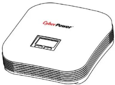
CPS1200EILCD/CPS2200EILCD User's Manual
IMPORTANT SAFETY INFORMATION
(SAVE THESE INSTRUCTIONS)
This manual contains important safety instructions. Please read and follow all instructions carefully during installation and operation of the unit. Read this manual thoroughly before attempting to unpack, install, or operate the inverter.
Insure the wall outlet and inverter are located near the equipment being attached for proper accessibility. To reduce risk of damage and injury, please use batteries with good quality.
Provide adequate ventilation for the battery compartment. The battery enclosure should be designed to prevent accumulation and concentration of hydrogen gas at the top of the compartment.
DO NOT expose the inverter to rain, snow or liquids of any type. The inverter is designed for indoor use only.
DO NOT obstruct the ventilation openings.
DO NOT connect neutral of the power distribution box on the wall to:
(a) The OUTPUT neutral of inverter.
or (b) The INPUT neutral of equipment.
Otherwise the reversed polarity will damage the inverter and the connected equipment.
![graph TD L["Utility power"] --> G["G"] N["N"] --> G HomeUPS["Home UPS"] --> Load["Load"] Load --> CommonNeutral["Common Neutral"] CommonNeutral --> X["X"] X --> Load](/content/2026/05/908004/images/6982982801596c18f5c9b85d35a92c55bf127632b09e6ad559355eb7d09783f2.jpg)
CAUTION! Risk of electric shock, do not remove cover. No user serviceable parts inside.
The battery can energize hazardous live parts inside even when the AC input power is disconnected.
To avoid electrical shock, turn off the inverter and unplug it from the AC power source before servicing the battery. Servicing the battery can only be performed by trained personnel.
INSTALLING YOUR HOME UPS SYSTEM
UNPACKING
Inspect the unit upon receipt. The box should contain the following:
Unit×1; Power Cord×1; User Manual×1
HOW TO DETERMINE THE POWER REQUIREMENTS OF YOUR EQUIPMENT
- Insure that the equipment plugged into the AC outlet does not exceed the inverter unit's rated capacity (1200VA/720W for CPS1200EILCD; 2200VA/1320W for CPS2200EILCD). If rated unit capacities are exceeded, an overload condition may occur and cause the HOME UPS unit to shut down or the circuit breaker trip.
- If the power requirements of your equipment are listed in units other than Volt-Amps (VA), convert Watts (W) or Amps (A) into VA by doing the calculations below. Note: The below equation only calculates the maximum amount of VA that the equipment can use, not what is typically used by the equipment at any one time. Users should expect usage requirements to be approximately 60% of below value.
TO ESTIMATE POWER REQUIREMENTS
-
220 V x ____ Amps (A) = ____ VA
-
Add the totals up for all pieces of equipment and multiply this total by 0.6 to calculate actual requirements. There are many factors that can affect the amount of power that your computer system will require. The total load that you will be placing on the battery-powered outlets should not exceed 80% of the unit's capacity.
HARDWARE INSTALLATION GUIDE
Before installation, please read and understand the following instructions:
- Placement
The inverter must be installed in a protected environment away from heat- emitting appliances such as a radiator or heat register. Do not install this product where excessive moisture is present.




- Ventilation
The location should provide adequate air flow around the inverter with 10 CM minimum clearance on all sides for proper ventilation.
- Connect the Battery
Connect the external battery with the DC cables from the back of the inverter. Follow battery polarity guide located near battery cables as below.
“+” Red cable for battery positive polarity;
“-” Black cable for battery negative polarity.

- Connect to AC and Charge the Battery
Connect the inverter to a wall outlet. Avoid using extension cords and adapter plugs. Charging the battery for at least 8 hours is recommended to insure that the battery is fully charged. To recharge the battery, simply leave the unit plugged into a wall outlet. To maintain optimal battery charge, leave the inverter plugged into an AC outlet at all times.
This unit can be charged even when it is not turned on.
- Connect the Load
Connect the equipment to the inverter outlet. Please make sure that the total loads of your equipments are less than the maximum total power load of the inverter.
BASIC OPERATION
FRONT PANEL DESCRIPTION

- LCD Module Display.
High resolution and intelligent LCD display shows all the inverter information with icons and messages. For more information please check the “Definitions for Illuminated LCD Indicators” section.
- Power Switch
Press the power switch to turn the inverter ON or OFF.
- LCD Function Selected Switch
The switch can be used to select the LCD display contents including input/output voltage and load percentage, etc.
REAR PANEL DESCRIPTION

- DC Input Cable (Black)
Connect to battery negative polarity.
- DC Input Cable (Red)
Connect to battery positive polarity.
- Input Circuit Breaker
The circuit breaker provides optimal overload protection.
4. Charger Current Control*
A. Select "20A, 10A" setting for default battery application. The charge current is 20A default, 10A respectively for CPS1200EILCD.
B. Select "Default" setting for general application. The charge voltage is 27.4V respectively for CPS2200EILCD.
C. Select "Customized" setting for special battery condition. The charge voltage is 26.6V, respectively for CPS2200EILCD.
*Note: Operated by trained professionals ONLY. Incorrect operation will damage the battery.
5. Input Voltage Range Selector
Input voltage range is defined in specification section. Output voltage is the same as input voltage in AC mode.
A. Select "Narrow" setting for general electrical appliance such as TUBE LIGHT, ENERGY SAVING LAMP, TV, JUICER & MIXER etc. It is not suitable for high-power motor or inductive load, such as the fridge of 1KW, the motor of 800W, AIR COOLER (having risk of rebooting) and so on. In this mode, the HOME UPS operating voltage in AC mode is within 190\~260Vac with the same output voltage. The line sensitivity is higher.
B. Select “Wide” setting to save energy. In this mode the operating range of voltage for the inverter is 100-280Vac. Therefore the output voltage will be the same as the MAINS input voltage. The unit in this mode has a lower sensitivity with a longer transfer time for switching from AC mode to battery mode in the event of power failure. You can safely connect and use home appliances which are not sensitive to transfer time limitations such as fluorescent tubes, bulbs, TV etc.
6. AC outlet**
The HOME UPS provides one outlet for connected equipment to insure temporary uninterrupted operation during a power failure and against surges and spikes.
7. AC Inlet
Connect to utility power through the input power cord.
Functional Test
AC Mode
The HOME UPS delivers power to the load derived from the utility and maintains proper battery charge.
On-Battery Mode
The inverter operates on battery when the utility voltage has fallen outside the limits. Local users are alerted to this mode of operation by visual and audible indicators. The HOME UPS provides power to the load from the battery and the output voltage of the inverter are regulated within a narrow range
1. Switch On
Press the power switch then the status LCD will light up.
2. Switch Off
Press again the power switch, the status LCD will go off.
3. Cold Start / Start on Battery:
This HOME UPS can be turned on even when AC is not present.
Press the power switch then the status LCD will light up.
ROUTINE MAINTENANCE AND STORAGE
ROUTINE MAINTENANCE
- Use dry soft clothes to clean the panel and plastic parts. Do not use any detergent that contains alcoholic ingredient.
- Unplug the HOME UPS from power inlet if the inverter will not operate for long period of time.
STORAGE
- First turn off your inverter and disconnect its power cord from the wall outlet. Disconnect all cables connected the HOME UPS to avoid battery drain.
- The HOME UPS should be stored in a cool dry location.
- Make sure the battery is fully charged before the inverter is stored.
- For extended storage in moderate climates, the battery should be charged for 12 hours every 3 months by plugging the power cord into the wall receptacle and turning on the main switch. Repeat it every 2 months in high temperature locations.
TROUBLE SHOOTING
| Problem | Possible Causes | Remedy |
| No LCD display | 1. Battery Weak | 1. Re-charge battery |
| 2. Battery defective | 2. Battery replacement. | |
| 3. Power switch is not pressed | 3. Press and hold power switch. | |
| Mains normal but not works in AC mode | 1. AC Input missing | 1. Check AC input connection. |
| 2. Input protector is effective | 2. Reset the input protector. | |
| Alarm buzzer beeps continuously | Overload | Verify that the load matches the capability specified in the specs. |
| Backup time is shortened | Overload | Remove some non-critical load. |
| Battery voltage is too low. | Charge battery for 8 hours or more. |
If any abnormal situations occur that are not listed above, please contact service personnel.
TECHNICAL SPECIFICATIONS
| Model | CPS1200EILCD | CPS2200EILCD |
| Capacity (VA) | 1200VA | 2200VA |
| Capacity (Watts) | 720W | 1320W |
| Input | ||
| Input Voltage Range | Wide mode: 100VAC-280VACNarrow mode: 190VAC-260VAC | |
| Frequency Range | 50/60Hz | |
| Output | ||
| On Battery Output Voltage | Simulated Sine Wave at 220Vac +/-10% | |
| On Battery Output Frequency | 50/60Hz | |
| Overload Protection | On Utility: Circuit Breaker, On Battery: Internal Current Limiting | |
| Physical | ||
| Total # of HOME UPS Receptacles | (1) UN | |
| Maximum Dimensions | 265mm(L)* 250mm(W)* 90mm(H) | |
| Weight | 2.05kg / 4.5Lbs | 2.2kg / 4.9Lbs |
| Battery | ||
| Lead Acid Battery | 12V | 24V |
| Warning Diagnostics | ||
| Indicators | HOME UPS Status Display, | |
| Audible Alarms | Low Battery, Overload, Fault | |
| Environmental | ||
| Operating Temperature | +32°F to 104°F (0°C to 40°C) | |
| Operating Relative Humidity | 0 to 90% NON-CONDENSING | |
| Management | ||
| Auto-Charger | Yes | |
| Auto-Restart | Yes | |
DEFINITIONS FOR ILLUMINATED LCD INDICATORS
LCD Indication

Line mode
| Select SW Press | HOME UPS Status Display | Capacity Display | Digital Value Display | ||||||
| Load Cap. | Battery Cap. | Input Voltage | Output Voltage | % of Load | |||||
| Initial | V | X | X | -- | X | V | V | ||
| 1st | V | X | X | -- | V | X | V | ||
| 2nd | V | X | X | -- | X | V | V | ||
| (Overload) | V | X | X | V | -- | -- | -- | -- | -- |
“V” : Illuminated, “X” : Not Illuminated, “--” : Either
Battery mode
| Select SW Press | HOME UPS Status Display | Capacity Display | Digital Value Display | ||||||
| Load Cap. | Battery Cap. | Input Voltage | Output Voltage | % of Load | |||||
| Initial | X | V | -- | -- | X | V | V | ||
| 1st | X | V | -- | -- | V | X | V | ||
| 2nd | X | V | -- | -- | X | V | V | ||
| Press >3sec (Sound Disable) | X | V | V | -- | -- | -- | -- | -- | -- |
| Press >3sec again (Sound Enable) | X | V | X | -- | -- | -- | -- | -- | -- |
| (Overload) | X | V | -- | V | -- | -- | -- | -- | -- |
“V” : Illuminated, “X” : Not Illuminated, “--” : Either
Off charging mode (Auto bypass)
| Select SW Press | HOME UPS Status Display | Capacity Display | Digital Value Display | ||||||
| Load Cap. | Battery Cap. | Input Voltage | Output Voltage | % of Load | |||||
| Initial | V | X | X | X | X | X | X | X | X |
“V” : Illuminated, “X” : Not Illuminated, “--“ : Either
Visit www.cyberpower.com for more product information and the nearest CyberPower local contact for your region.
Entire contents copyright © 2017 CyberPower Systems, Inc All rights reserved. Reproduction in whole or in part without permission is prohibited.


- IMPORTANT SAFETY INFORMATION
- (SAVE THESE INSTRUCTIONS)
- INSTALLING YOUR HOME UPS SYSTEM
- UNPACKING
- HOW TO DETERMINE THE POWER REQUIREMENTS OF YOUR EQUIPMENT
- TO ESTIMATE POWER REQUIREMENTS
- HARDWARE INSTALLATION GUIDE
- BASIC OPERATION
- FRONT PANEL DESCRIPTION
- REAR PANEL DESCRIPTION
- CHARGER CURRENT CONTROL
- INPUT VOLTAGE RANGE SELECTOR
- AC OUTLET
- AC INLET
- FUNCTIONAL TEST
- AC MODE
- ON-BATTERY MODE
- SWITCH ON
- SWITCH OFF
- COLD START / START ON BATTERY
- ROUTINE MAINTENANCE AND STORAGE
- ROUTINE MAINTENANCE
- STORAGE
- DEFINITIONS FOR ILLUMINATED LCD INDICATORS
Marke : CyberPower
Modell : CPS2200EILCD
Kategorie : Solarinstallation