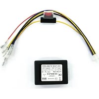
CA-ECO-UNI.003 - Spannungsstabilisator PIONEER - Kostenlose Bedienungsanleitung
Finden Sie kostenlos die Bedienungsanleitung des Geräts CA-ECO-UNI.003 PIONEER als PDF.


| Produkttyp | Universelles Steuergerät (Öko-Modus) |
| Modellnummer | CA-ECO-UNI.003 |
| Marke | Pioneer |
| Farbe | Schwarz |
| Abmessungen (B x H x T) | 12,0 x 2,5 x 6,5 cm |
| Gewicht | 85 g |
| Stromversorgung | Batteriebetrieben (2 x AAA, nicht im Lieferumfang) |
| Batterielebensdauer | Ca. 12 Monate bei normalem Gebrauch |
| Hauptfunktionen | Ein-/Ausschalten, Energiesparmodus, Signalempfang |
| Reichweite | Bis zu 10 m im Freien |
| Kompatible Geräte | Pioneer Audio-/Videogeräte mit IR-Empfänger |
| Betriebstemperatur | 0°C bis 40°C |
| Lagertemperatur | -20°C bis 60°C |
| Material | Kunststoff, recyclebar |
| Wartung und Reinigung | Mit einem weichen, trockenen Tuch abwischen. Keine scharfen Reinigungsmittel. |
| Sicherheitshinweise | Nicht in Wasser eintauchen. Von Kindern fernhalten. Bei Beschädigung nicht verwenden. |
| Ersatzteile und Reparierbarkeit | Ersatzbatterien im Handel erhältlich. Reparatur nur durch Fachpersonal. |
| Umweltinformationen | Entsorgung gemäß lokalen Vorschriften für Elektronikschrott. |
| Lieferumfang | 1x CA-ECO-UNI.003, Bedienungsanleitung |
Häufig gestellte Fragen - CA-ECO-UNI.003 PIONEER
Benutzerfragen zu CA-ECO-UNI.003 PIONEER
0 Frage zu diesem Gerät. Beantworten Sie die, die Sie kennen, oder stellen Sie Ihre eigene.
Eine neue Frage zu diesem Gerät stellen
Laden Sie die Anleitung für Ihr Spannungsstabilisator kostenlos im PDF-Format! Finden Sie Ihr Handbuch CA-ECO-UNI.003 - PIONEER und nehmen Sie Ihr elektronisches Gerät wieder in die Hand. Auf dieser Seite sind alle Dokumente veröffentlicht, die für die Verwendung Ihres Geräts notwendig sind. CA-ECO-UNI.003 von der Marke PIONEER.
BEDIENUNGSANLEITUNG CA-ECO-UNI.003 PIONEER
Technical Description:
| Min Max | ||
| Operating Input voltage range 7 Vdc 12 Vdc | ||
| Operating Output voltage 12 Vdc* | ||
| Permanent Out current | 5A dc continuous Up to 10A for 6 seconds | |
| Key Out current 100 mA | ||
| Standby consumption < 5 mA | ||
| Key In consumption < 1 mA | ||
| Max output power 120 W | ||
| Efficiency - 90% | ||
| Overcurrent/Short protection | YES (EXT FUSE) | |
| Polarity reversal protection | YES (EXT FUSE) | |
| Operating Temperature | -40°C ÷ +85°C | |
| Dimensions | 75x25x55mm | |
| Weight | 300g | |
| Certifications | E24(NSAI) approved according to R10-04 | |
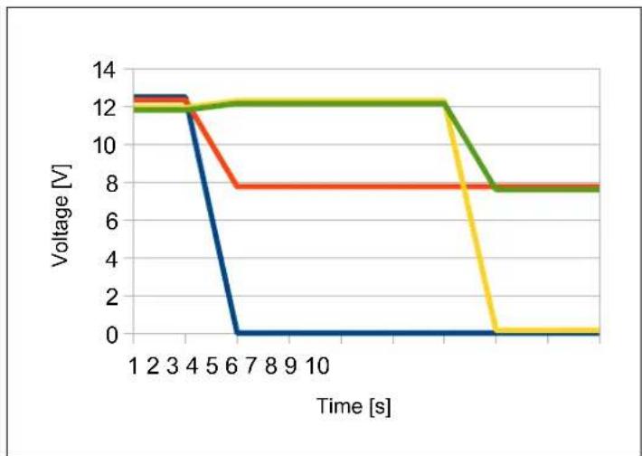
*The circuit only operates in a range of input voltage going from 7V to 12V. Outside this range the circuit stops to operate and the output voltage follows the input voltage minus 0.6V. The Key Out signal is conditioned by the status of the Key In and by the operating state of the regulator (see graphics on page 2), and it is available as a signal for the car stereo.
This harness allows to connect:
-YELLOW/RED: 7÷12Vdc input (Permanent In)
- BLUE: 7÷9Vdc input ignition key (Key In)
- YELLOW: 12Vdc output (Permanent Out)
- RED: 12V output key (Key Out)
- BLACK + BLACK: GND (both internally shorted)

10R-041548

Functional charts

line
| Time [s] | KEY IN | PERMANENT IN | KEY OUT | PERMANENT OUT | | -------- | ------ | ------------ | ------- | ------------- | | 1 | 12.5 | 12.4 | 12.3 | 12.2 | | 2 | 12.5 | 12.4 | 12.3 | 12.2 | | 3 | 12.5 | 12.4 | 12.3 | 12.2 | | 4 | 12.5 | 12.4 | 12.3 | 12.2 | | 5 | 12.5 | 12.4 | 12.3 | 12.2 | | 6 | 12.5 | 12.4 | 12.3 | 12.2 | | 7 | 12.5 | 12.4 | 12.3 | 12.2 | | 8 | 12.5 | 12.4 | 12.3 | 12.2 | | 9 | 12.5 | 12.4 | 12.3 | 12.2 | | 10 | 12.5 | 12.4 | 12.3 | 12.2 |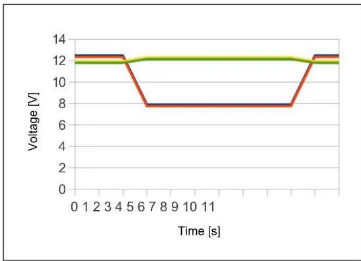
line
| Time [s] | Voltage [V] (Red) | Voltage [V] (Green) | | -------- | ----------------- | ------------------- | | 0 | 12.5 | 12.0 | | 1 | 12.5 | 12.0 | | 2 | 12.5 | 12.0 | | 3 | 12.5 | 12.0 | | 4 | 12.5 | 12.0 | | 5 | 8.0 | 12.0 | | 6 | 8.0 | 12.0 | | 7 | 8.0 | 12.0 | | 8 | 8.0 | 12.0 | | 9 | 8.0 | 12.0 | | 10 | 8.0 | 12.0 | | 11 | 8.0 | 12.0 | | 12 | 8.0 | 12.0 | | 13 | 12.5 | 12.0 | | 14 | 12.5 | 12.0 | | 15 | 12.5 | 12.0 | | 16 | 12.5 | 12.0 | | 17 | 12.5 | 12.0 | | 18 | 12.5 | 12.0 | | 19 | 12.5 | 12.0 | | 20 | 12.5 | 12.0 | | 21 | 12.5 | 12.0 | | 22 | 12.5 | 12.0 | | 23 | 12.5 | 12.0 | | 24 | 12.5 | 12.0 | | 25 | 12.5 | 12.0 | | 26 | 12.5 | 12.0 | | 27 | 12.5 | 12.0 | | 28 | 12.5 | 12.0 | | 29 | 12.5 | 12.0 | | 30 | 12.5 | 12.0 | | 31 | 12.5 | 12.0 | | 32 | 12.5 | 12.0 | | 33 | 12.5 | 12.0 | | 34 | 12.5 | 12.0 | | 35 | 12.5 | 12.0 | | 36 | 12.5 | 12.0 | | 37 | 12.5 | 12.0 | | 38 | 12.5 | 12.0 | | 39 | 12.5 | 12.0 | | 40 | 12.5 | 12.0 | | 41 | 12.5 | 12.0 | | 42 | 12.5 | 12.0 | | 43 | 12.5 | 12.0 | | 44 | 12.5 | 12.0 | | 45 | 12.5 | 12.0 | | 46 | 12.5 | 12.0 | | 47 | 12.5 | 12.0 | | 48 | 12.5 | 12.0 | | 49 | 12.5 | 12.0 | | 50 | 12.5 | 12.0 | | 51 | 12.5 | 12.0 | | 52 | 12.5 | 12.0 | | 53 | 12.5 | 12.0 | | 54 | 12.5 | 12.0 | | 55 | 12.5 | 12.0 | | 56 | 8.0 | 12.0 | | 57 | 8.0 | 12.0 | | 58 | 8.0 | 12.0 | | 59 | 8.0 | 12.0 | | 60 | 8.0 | 12.0 | | 61 | 8.0 | 12.0 | | 62 | 8.0 | 12.0 | | 63 | 8.0 | 12.0 | | 64 | 8.0 | 12.0 | | 65 | 8.0 | 12.0 | | 66 | 8.0 | 12.0 | | 67 | 8.0 | 12.0 | | 68 | 8.0 | 12.0 | | 69 | 8.0 | 12.0 | | 70 | 8.0 | 12.0 | | Note: The actual values for the red and green lines are not provided in the code snippet, so they are represented as placeholders (e.g., “Voltage [V]”, “Time [s].”).)
line
| Time [s] | Voltage [V] (Red) | Voltage [V] (Green) | Voltage [V] (Yellow) | | -------- | ----------------- | ------------------- | -------------------- | | 1 | 12.5 | 12.0 | 12.0 | | 2 | 12.5 | 12.0 | 12.0 | | 3 | 12.5 | 12.0 | 12.0 | | 4 | 12.5 | 12.0 | 12.0 | | 5 | 8.0 | 12.0 | 12.0 | | 6 | 8.0 | 12.0 | 12.0 | | 7 | 8.0 | 12.0 | 12.0 | | 8 | 8.0 | 12.0 | 12.0 | | 9 | 8.0 | 12.0 | 12.0 | | 10 | 8.0 | 12.0 | 12.0 | | 11 | 8.0 | 12.0 | 12.0 | | 12 | 8.0 | 12.0 | 12.0 | | 13 | 8.0 | 12.0 | 12.0 | | 14 | 8.0 | 12.0 | 12.0 | | 15 | 8.0 | 12.0 | 12.0 | | 16 | 8.0 | 12.0 | 12.0 | | 17 | 8.0 | 12.0 | 12.0 | | 18 | 8.0 | 12.0 | 12.0 | | 19 | 8.0 | 12.0 | 12.0 | | 20 | 8.0 | 12.0 | 12.0 | | 21 | 8.0 | 12.0 | 12.0 | | 22 | 8.0 | 12.0 | 12.0 | | 23 | 8.0 | 12.0 | 12.0 | | 24 | 8.0 | 12.0 | 12.0 | | 25 | 8.0 | 12.0 | 12.0 | | 26 | 8.0 | 12.0 | 12.0 | | 27 | 8.0 | 12.0 | 12.0 | | 28 | 8.0 | 12.0 | 12.0 | | 29 | 8.0 | 12.0 | 12.0 | | 30 | 8.0 | 12.0 | 12.0 | | 31 | 8.0 | 12.0 | 12.0 | | 32 | 8.0 | 12.0 | 12.0 | | 33 | 8.0 | 12.0 | 12.0 | | 34 | 8.0 | 12.0 | 12.0 | | 35 | 8.0 | 12.0 | 12.0 | | 36 | 8.0 | 12.0 | 12.0 | | 37 | 8.0 | 12.0 | 12.0 | | 38 | 8.0 | 12.0 | 12.0 | | 39 | 8.0 | 12.0 | 12.0 | | 40 | 8.0 | 12.0 | 12.0 | | 41 | 8.0 | 12.0 | 12.0 | | 42 | 8.0 | 12.0 | 12.0 | | 43 | 8.0 | 12.0 | 12.0 | | 44 | 8.0 | 12.0 | 12.0 | | 45 | 8.0 | 12.0 | 12.0 | | 46 | 8.0 | 12.0 | 12.0 | | 47 | 8.0 | 12.0 | 12.0 | | 48 | 8.0 | 12.0 | 12.0 | | 49 | 8.0 | 12.0 | 12.0 | | 50 | 8.0 | 12.0 | 12.0 | | Note: The actual values for Voltage [V] are not provided in the code snippet, so they are calculated based on the original data source used in the code snippet for each data point in the chart.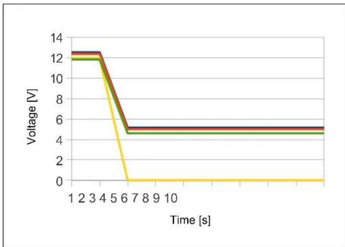
line
| Time [s] | Voltage [V] (Blue) | Voltage [V] (Red) | Voltage [V] (Green) | Voltage [V] (Yellow) | | -------- | ------------------ | ----------------- | ------------------- | -------------------- | | 1 | 12.5 | 12.5 | 12.0 | 12.0 | | 2 | 12.5 | 12.5 | 12.0 | 12.0 | | 3 | 12.5 | 12.5 | 12.0 | 12.0 | | 4 | 12.5 | 12.0 | 12.0 | 12.0 | | 5 | 0.0 | 8.0 | 12.0 | 12.0 | | 6 | 0.0 | 8.0 | 12.0 | 12.0 | | 7 | 0.0 | 8.0 | 12.0 | 12.0 | | 8 | 0.0 | 8.0 | 12.0 | 12.0 | | 9 | 0.0 | 8.0 | 12.0 | 12.0 | | 10 | 0.0 | 8.0 | 12.0 | 12.0 | | 11 | 0.0 | 8.0 | 8.0 | 8.0 | | 12 | 0.0 | 8.0 | 8.0 | 8.0 | | 13 | 0.0 | 8.0 | 8.0 | 8.0 | | 14 | 0.0 | 8.0 | 8.0 | 8.0 | | 15 | 0.0 | 8.0 | 8.0 | 8.0 | | 16 | 0.0 | 8.0 | 8.0 | 8.0 | | 17 | 0.0 | 8.0 | 8.0 | 8.0 | | 18 | 0.0 | 8.0 | 8.0 | 8.0 | | 19 | 0.0 | 8.0 | 8.0 | 8.0 | | 20 | 0.0 | 8.0 | 8.0 | 8.0 | | 21 | 0.0 | 8.0 | 8.0 | 8.0 | | 22 | 0.0 | 8.0 | 8.0 | 8.0 | | 23 | 0.0 | 8.0 | 8.0 | 8.0 | | 24 | 0.0 | 8.0 | 8.0 | 8.0 | | 25 | 0.0 | 8.0 | 8.0 | 8.0 | | 26 | 0.0 | 8.0 | 8.0 | 8.0 | | 27 | 0.0 | 8.0 | 8.0 | 8.0 | | 28 | 0.0 | 8.0 | 8.0 | 8.0 | | 29 | 0.0 | 8.0 | 8.0 | 8.0 | | 30 | 0.0 | 8.0 | 8.0 | 8.0 | | 31 | 0.0 | 8.0 | 8.0 | 8.0 | | 32 | 0.0 | 8.0 | 8.0 | 8.0 | | 33 | 0.0 | 8.0 | 8.0 | 8.0 | | 34 | 0.0 | 8.0 | 8.0 | 8.0 | | 35 | 0.0 | 8.0 | 8.0 | 8.0 | | 36 | 0.0 | 8.0 | 8.0 | 8.0 | | 37 | 0.0 | 8.0 | 8.0 | 8.0 | | 38 | 0.0 | 8.0 | 8.0 | 8.0 | | 39 | 0.0 | 8.0 | 8.0 | 8.0 | | 40 | 0.0 | 8.0 | 8.0 | 8.0 | | Note: The actual values are not provided in the code provided in the code execution, so they are calculated based on the provided code format rules used in the code execution.Note: Fall times is purely indicative.
The charts show the default behavior; customized versions are available with regard to the management of the timing of the outputs.
The manufacturer will reserve to make technical changes to the device without notice.
All installation work must be performed by a qualified professional installer only.
The manufacturer / dealer is not liable for any kind of incidental or indirect damages.

Marke : PIONEER
Modell : CA-ECO-UNI.003
Kategorie : Spannungsstabilisator