PHA0150 - Nicht kategorisiert Rigol - Kostenlose Bedienungsanleitung
Finden Sie kostenlos die Bedienungsanleitung des Geräts PHA0150 Rigol als PDF.


| Produkttyp | Hochspannungs-Differenztastkopf |
| Modell | PHA0150 |
| Marke | Rigol |
| Bandbreite | 50 MHz |
| Max. Differenzspannung | 1300 V (DC + AC Spitze) |
| Max. Gleichtaktspannung | 1000 V CAT II |
| Eingangsimpedanz | 10 MΩ // 3 pF (jeweils gegen Erde) |
| Dämpfungsverhältnisse | 50× / 500× |
| Genauigkeit | ±3 % |
| Ausgangsspannungsbereich | ±7 V bei 50 Ω Last |
| Versorgungsspannung | 9-V-Batterie (6LR61) oder USB-C (5 V, 1 A) |
| Stromaufnahme | ca. 250 mA (bei USB) |
| Kabellänge | 1,2 m |
| Gewicht | ca. 400 g |
| Abmessungen (B x H x T) | 160 x 70 x 25 mm |
| Betriebstemperaturbereich | 0 °C bis 40 °C |
| Lagertemperaturbereich | -20 °C bis 70 °C |
| Sicherheitsnormen | EN 61010-1, CAT II 1000 V |
| Gehäusematerial | ABS-Kunststoff |
| Lieferumfang | Tastkopf, Prüfspitzen, Krokodilklemmen, USB-Kabel, Tragetasche, Bedienungsanleitung |
| Garantie | 3 Jahre |
Häufig gestellte Fragen - PHA0150 Rigol
Benutzerfragen zu PHA0150 Rigol
0 Frage zu diesem Gerät. Beantworten Sie die, die Sie kennen, oder stellen Sie Ihre eigene.
Eine neue Frage zu diesem Gerät stellen
Laden Sie die Anleitung für Ihr Nicht kategorisiert kostenlos im PDF-Format! Finden Sie Ihr Handbuch PHA0150 - Rigol und nehmen Sie Ihr elektronisches Gerät wieder in die Hand. Auf dieser Seite sind alle Dokumente veröffentlicht, die für die Verwendung Ihres Geräts notwendig sind. PHA0150 von der Marke Rigol.
BEDIENUNGSANLEITUNG PHA0150 Rigol
RIGOL
User Guide
PHA High-Voltage Differential Probe
Apr. 2022
RIGOL TECHNOLOGIES CO., LTD
Guaranty and Declaration
Copyright
© 2022 RIGOL TECHNOLOGIES CO., LTD. All Rights Reserved.
Trademark Information
RIGOL® is the trademark of RIGOL TECHNOLOGIES CO., LTD.
Publication Number
UGE33101-1110
Notices
● RIGOL products are covered by P.R.C. and foreign patents, issued and pending.
- RIGOL reserves the right to modify or change parts of or all the specifications and pricing policies at the company's sole decision.
● Information in this publication replaces all previously released materials.
● Information in this publication is subject to change without notice.
● RIGOL shall not be liable for either incidental or consequential losses in connection with the furnishing, use, or performance of this manual, as well as any information contained.
● Any part of this document is forbidden to be copied, photocopied, or rearranged without prior written approval of RIGOL.
Product Certification
RIGOL guarantees that this product conforms to the national and industrial standards in China as well as the ISO9001:2015 standard and the ISO14001:2015 standard. Other international standard conformance certifications are in progress.
Contact Us
If you have any problem or requirement when using our products or this manual, please contact RIGOL.
E-mail: service@rigol.com
Website: www.rigol.com
General Safety Summary
CAUTION
This device involves the high-voltage measurement. To use the device safely and ensure your personal safety, please carefully read and observe the instructions specified in this manual before using the device.
Safety Terms and Symbols
Before using the device, read the following safety notices carefully.
 | The ⚠ symbol printed on the device indicates that the user should refer to a corresponding topic in the manual (marked with the ⚠ symbol) before using the relevant function.In the manual, the ⚠ symbol indicates particularly important information that the user should read before using the device. |
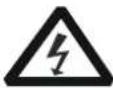 | The ⚠ symbol printed on the device indicates high voltage warning. |
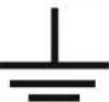 | The ⚠ symbol printed on the device indicates test ground. |
Safety Precautions
CAUTION
● Beware of high voltages to avoid electric shock. Understand the maximum input voltage for the probe.
- Do not operate in wet conditions or in an explosive atmosphere.
● Before use, please check whether the exterior of the probe is damaged. If damaged, stop using it.
● Turn off the circuit under test before connecting it to the probe.
- When connecting the BNC output cable of the probe to the oscilloscope or other devices, ensure that the BNC terminal is safely grounded.
● After measurement, turn off the circuit first and then remove the probe.
Contents
Guaranty and Declaration...... I
General Safety Summary ......II
Safety Terms and Symbols....II
Safety Precautions....III
General Inspection ....1
PHA High-Voltage Differential Probe 2
Probe Components....4
Probe Component Description....5
To Use the Probe ....7
Preparation for Measurement....7
Measurement Steps....7
Precautions During Measurement....9
Failures and Troubleshooting 11
Specifications 12
Technical Specifications....12
Mechanical Characteristics....13
Working Environment....14
Appendix 15
Appendix 1 Max. Differential Mode Voltage vs Freq. ..... 15
Appendix 2 Package List....15
Appendix 3 Warranty 15
General Inspection
1. Inspect the packaging
RIGOL has carried out strict inspections on each product before leaving the factory. When you receive the product, please check whether the packaging is intact. If the packaging has been damaged, do not dispose the damaged packaging or cushioning materials until the shipment has been checked for completeness and the probe has passed both electrical and mechanical tests.
The consigner or carrier shall be liable for the damage to the instrument resulting from shipment. RIGOL would not be responsible for free maintenance/rework or replacement of the instrument.
2. Check the probe
In case of any mechanical damage, missing parts, or failure in passing the electrical and mechanical tests, contact your RIGOL sales representative.
3. Check the accessories
Please check the accessories according to Appendix 2 Package List in this manual. If the accessories are damaged or incomplete, please contact your RIGOL sales representative.
PHA High-Voltage Differential Probe
The PHA series high-voltage differential probe (hereinafter referred to as PHA series probe) connects to the voltage under test through the high-voltage differential input cable to convert the input high voltage into the low voltage, and then display the waveforms on the waveform measuring instrument by connecting its output interface to the waveform measuring instrument.
Main Features
● High bandwidth to meet the requirements of most high-frequency test system
PHA0150: 70 MHz;
PHA1150: 100 MHz;
PHA2150: 200MHz
- Diversified ranges and two attenuations to meet the requirements for most common-mode test circuit
50X: 150 V (DC + peak AC);
500X: 1500 V (DC + peak AC);
- 5 MHz bandwidth limit ^[1]
For the low-frequency signal measurement, this function can reduce the noise and interference of high-frequency signals to meet the
measurement requirement for the switching frequency of most switching transistors (FETs) in the switching power supply.
● High-voltage differential input mode
● Higher input impedance and lower input capacitive on the input terminal ensure accurate and fast measurement
● Sound common-mode noise rejection
- Standard BNC output terminal, compatible with the waveform measuring instruments of most manufacturers.
● Audible alarm beeper and visible indicator blinking for sounding the alarm;
the alarm can be disabled manually
● Auto memory function, capable of automatically saving the working status that was set before it is shutdown
Note[1]:
When the bandwidth is limited to 5 MHz, the internal output circuit of the PHA series probe is connected to a 5 MHz low-pass network. The low-pass network can reduce the high-frequency components, the noise, and the harmonics, which is conducive to the testing and analysis of the low-frequency signals.
Measurement Scenarios
The PHA series probe is mainly used in scenarios where high-voltage floating measurement is required, such as
- Floating voltage measurement
- Switching power supply design
● inverter/UPS power measurement - Inverter measurement
● Electronic ballast design - CRT display design
● Low-voltage apparatus test
● Strong current or high voltage isolation measurement
● Power conversion and other related designs
● welding/plating power measurement
● Frequency conversion home appliance measurement: induction heating; induction cooker - Motor drive design
● Electrical engineering experiment
● Power electronics and power drives experiment
Probe Components
The PHA series probe consists of PHA0150, PHA1150 and PHA2150. This manual takes PHA1150 as an example to introduce the components of the PHA series probe.
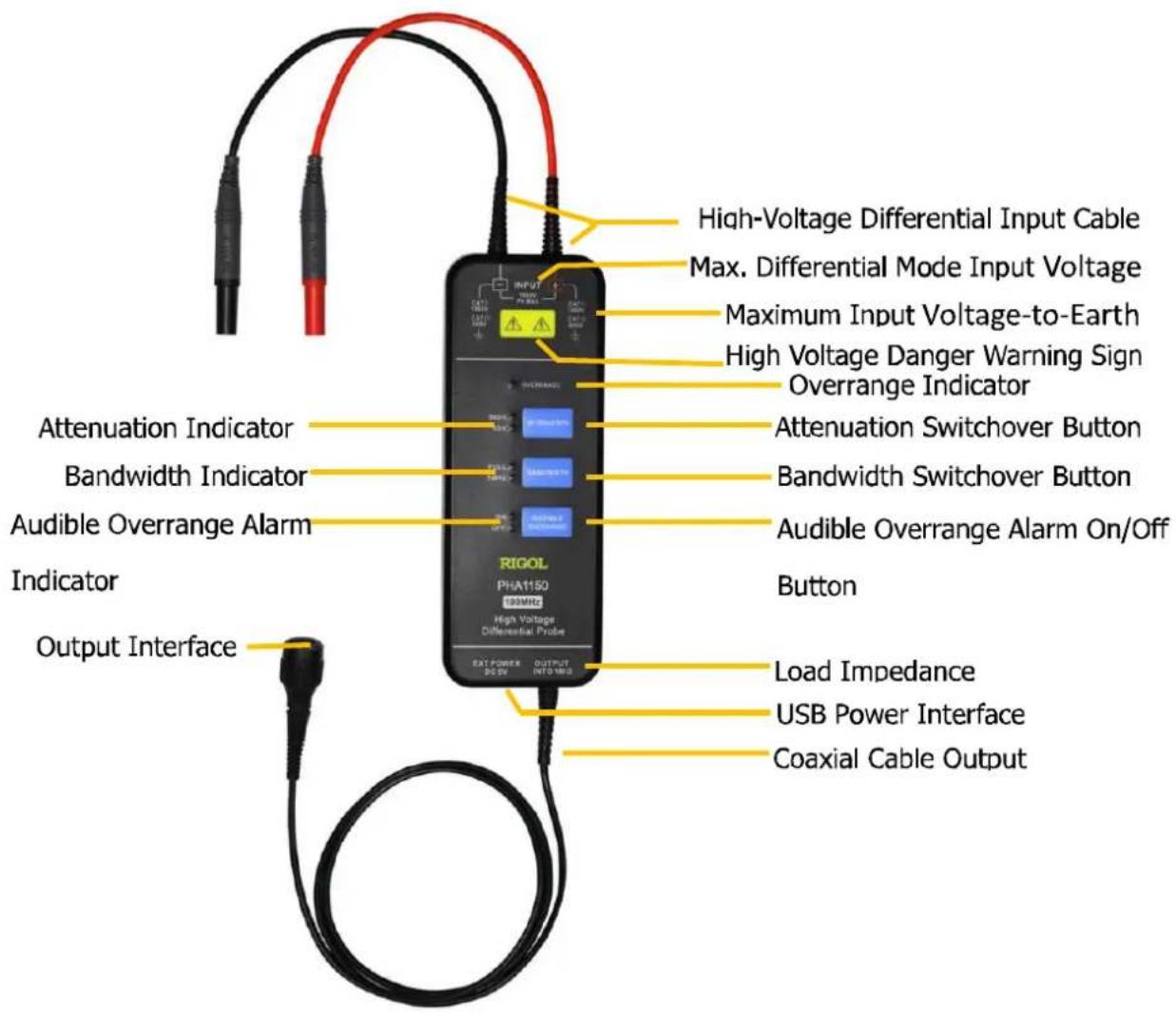
Figure 1 PHA1150 High-Voltage Differential Probe
By default, 500X is selected for OVERRANGE; FULL is selected for BANDWIDTH; and ON is selected for AUDIBLE OVERRANGE.
Probe Component Description
● High-Voltage Differential Input Cable
Used to measure the input voltage signal after connecting it to the insulated plunger hook clip. It can be extended with the extender leads (approx. 1 m). When using the extender leads, the frequency of the signal under test should be below 5 MHz.
● Max. Differential Mode Input Voltage
1500 V (DC + peak AC)
• Overrange Indicator
When the voltage under test exceeds the probe range, the overrange indicator lights on.
• Attenuation Switchover Button
Press this button to switch over between the voltage range (attenuation) settings of the probe. For the PHA series probe, two attenuation ratios are available: 500X and 50X.
✿ 50X indicates that the max. measurement voltage is 150 V.
✿ 500X indicates that the max. measurement voltage is 1500 V.
● Bandwidth Switchover Button
Press this button to switch over between the bandwidth. The PHA series probe supports two bandwidths.
✿ FULL: indicates the full specified bandwidth of the probe. For PHA0150, its full bandwidth is 70 MHz; for PHA1150, its full bandwidth is 100 MHz; for PHA2150, its full bandwidth is 200 MHz.
✿ 5 MHz: When measuring the low-frequency signal, to reduce the interference of the high-frequency signal, you can select the 5 MHz bandwidth.
● Audible Overrange Alarm On/Off Button
ON: Turns on the alarm beeper.
◇ OFF: Turns off the alarm beeper.
When ON, an audible alarm will be sounded once the voltage under test exceeds the probe range.
- Load Impedance
The output impedance of the probe is 50 . When the input impedance of the load (e.g. oscilloscope) is 1 M , the measured signal amplitude is input amplitude. When the input impedance of the load is set to 50 , the high-frequency amplitude-frequency characteristics will be flatter, and the measured signal amplitude is half of the input amplitude.
- USB Power Interface
A standard USB Type-C interface. It provides power with a standard USB adapter. You can connect it with the oscilloscope to provide power for the probe; or use the mobile power supply to charge for the probe. The power specification should be DC 5 V, 1 A.
- Output Interface
indicates a standard BNC output terminal, which is compatible with the waveform measuring instruments of most manufacturers.
To Use the Probe
Before using the current probe, make sure to refer to Safety Precautions.
Preparation for Measurement
- Evaluate the amplitude of the voltage under test and check whether it is within the voltage range of the probe. If it is beyond the max. range of the probe, please replace a proper probe. Otherwise, the measurement would be incorrect or the probe may be damaged. Even worse, this may lead to safety accidents.
- Prepare one power adapter (DC 5 V, 1 A).
- Connect the probe to power source and have a 20-minute warm-up at least. Meanwhile, prepare one measuring instrument (e.g. an oscilloscope).
- Please ensure that the device under test is powered off or the output is disabled.
Measurement Steps
Check and ensure that the measurement system is safe. Make sure that the above preparation for measurement is ready.
- Connect the output cable of the probe to the input terminal of the measuring instrument.
- Use the USB Type-C cable to connect its one end to the specified power adapter and the other end to the power interface of the probe. Insert the power adapter into the socket to provide power to the probe. If the indicators on the panel light on normally, it indicates that the probe has been launched normally.
- Select a proper range for the probe based on the measuring voltage.
- Select the proper attenuation ratio of the measuring instrument based on
the probe range. Then adjust the range of the instrument based on the voltage under test.
-
Select a proper probe clip according to the object under test. Connect one end of the clip to the input cable of the probe and connect the other end to the object under test.
-
Turn on the device under test to start testing.
During testing, keep the probe body far away from the high-voltage pulse circuit to reduce interference to the probe.
CAUTION
When the voltage under test exceeds the probe range, the overrange indicator lights on. If ON is selected for AUDIBLE OVERRANGE, it will sound an alarm. At this time, please turn off the device under test immediately.
After the test is completed, disconnect power from the circuit under test first, and then turn off the power of the probe. Disconnect two input terminals of the probe from the test point, and disconnect the output BNC connector from the measuring instrument.
When the extender leads are used, the connection steps are as follows:
-
Connect one end of the double-ended BNC coaxial cable to the BNC terminal of the high-voltage differential probe, and connect the other end to the input terminal of the oscilloscope.
-
Connect the output cable and input cable to the probe.
Precautions During Measurement
CAUTION
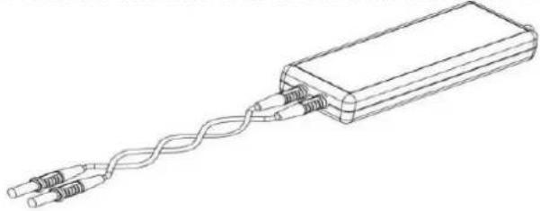
- Before measurement, try to twist the high-voltage differential input cables as much as possible, which can better reduce the interference of the lead inductance and external noise to improve the anti-interference ability of the probe. The twisting method is shown in the figure below:
natural_image
Line drawing of a rectangular electronic device with two coiled wires attached (no text or symbols)Figure 2 Twisting the High-Voltage Differential Input Cable
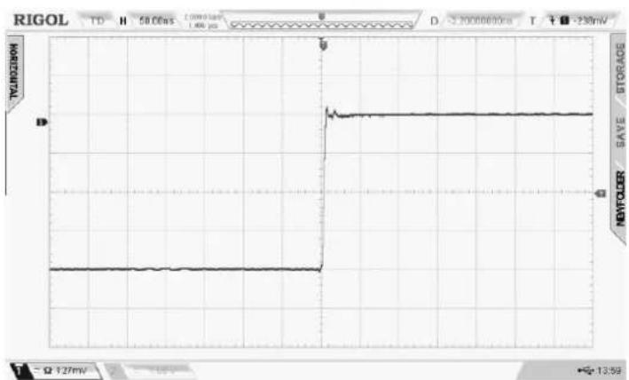
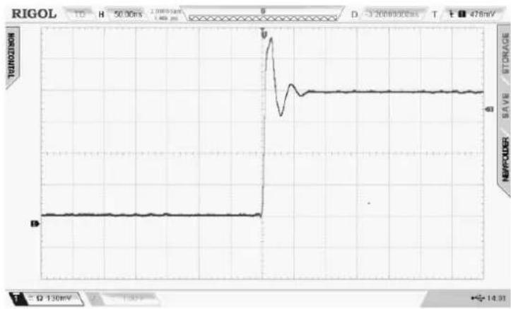
- Try not to extend the input cable, as this will bring more noises. If you have to extend the cable, extend the cable with the same length. Besides, the input frequency should not be greater than 5 MHz. Otherwise, errors will occur for the output, as shown in the figure below.
line
| Time (ns) | Voltage | | --------- | ------- | | 0 | 50.00 | | 2.5 | 50.00 | | 3.0 | 50.00 | | 3.5 | 50.00 | | 4.0 | 50.00 | | 4.5 | 50.00 | | 5.0 | 50.00 | | 5.5 | 50.00 | | 6.0 | 50.00 | | 6.5 | 50.00 | | 7.0 | 50.00 | | 7.5 | 50.00 | | 8.0 | 50.00 | | 8.5 | 50.00 | | 9.0 | 50.00 | | 9.5 | 50.00 | | 10.0 | 50.00 | | 10.5 | 50.00 | | 11.0 | 50.00 | | 11.5 | 50.00 | | 12.0 | 50.00 | | 12.5 | 50.00 | | 13.0 | 50.00 | | 13.5 | 50.00 | | 14.0 | 50.00 | | 14.5 | 50.00 | | 15.0 | 50.00 | | 15.5 | 50.00 | | 16.0 | 50.00 | | 16.5 | 50.00 | | 17.0 | 50.00 | | 17.5 | 50.00 | | 18.0 | 50.00 | | 18.5 | 50.00 | | 19.0 | 50.00 | | 19.5 | 50.00 | | 20.0 | 50.00 | | 20.5 | 50.00 | | 21.0 | 50.00 | | 21.5 | 50.00 | | 22.0 | 50.00 | | 22.5 | 50.00 | | 23.0 | 50.00 | | 23.5 | 50.00 | | 24.0 | 50.00 | | 24.5 | 50.00 | | 25.0 | 50.00 | | 25.5 | 50.00 | | 26.0 | 50.00 | | 26.5 | 50.00 | | 27.0 | 50.00 | | 27.5 | 50.00 | | 28.0 | 50.00 | | 28.5 | 50.00 | | 29.0 | 50.00 | | 29.5 | 50.00 | | 30.0 | 50.00 | | 31.0 | 51.47 | | 32.5 | 53.84 | | 34.5 | 64.31 | | 36.5 | 74.78 | | 38.5 | 84.24 | | 41.5 | 94.69 | | 44.5 | 1,276 | | 47.5 | - | | 51 | - | | - | - | | - | - | | - | - | | - | - | | - | - | | - | - | | - | - | | - | - | | - | - | | - | - | | - | - | | - | - | | - | - | | - | - | | - | +127 | | - | +166 | | - | +216 | | - | +276 | | - | +336 | | - | +396 | | - | +466 | | - | +536 | | - | +616 | | - | +696 | | - | +786 | | - | +876 | | - | +966 | | - | +1,276 | | - | +1,666 | | - | +2,166 | | - | +2,766 | | - | +3,366 | | - | +4,166 | | - | +4,966 | | - | +5,866 | | - | +6,766 | | - | +7,666 | | - | +8,666 | | - | +9,666 | | - | +1,276 | | - | +1,666 | | - | +2,166 | | - | +2,766 | | - | +3,366 | | - | +4,166 | | - | +4,966 | | - | +6,766 | | - | +7,666 | | - | +8,666 | | - | +9,666 | | - | +1,276 | | - | +1,666 | | - | +2,166 | | - | +2,766 |Figure 3 Waveforms Generated without Extending the Input Cable
line
| Time (μs) | Voltage (V) | |-----------|-------------| | 0 | 0 | | 50 | 0 | | 100 | 0 | | 150 | 0 | | 200 | 0 | | 250 | 0 | | 300 | 0 | | 350 | 0 | | 400 | 0 | | 450 | 0 | | 500 | 0 | | 550 | 0 | | 600 | 0 | | 650 | 0 | | 700 | 0 | | 750 | 0 | | 800 | 0 | | 850 | 0 | | 900 | 0 | | 950 | 0 | | 1000 | 0 | | 1050 | 0 | | 1100 | 0 | | 1150 | 0 | | 1200 | 0 | | 1250 | 0 | | 1300 | 0 | | 1350 | 0 | | 1400 | 0 | | 1450 | 0 | | 1500 | 0 | | 1550 | 0 | | 1600 | 0 | | 1650 | 0 | | 1700 | 0 | | 1750 | 0 | | 1800 | 0 | | 1850 | 0 | | 1900 | 0 | | 1950 | 0 | | 2000 | 0 | | 2050 | 0 | | 2100 | 0 | | 2150 | 0 | | 2200 | 0 | | 2250 | 0 | | 2300 | 0 | | 2350 | 0 | | 2400 | 0 | | 2450 | 0 | | 2500 | 0 | | 2550 | 0 | | 2600 | 0 | | 2650 | 0 | | 2700 | 0 | | 2750 | 0 | | 2800 | 0 | | 2850 | 0 | | 2900 | 0 | | 2950 | 0 | | 3000 | 0 | | 3050 | 0 | | 3100 | 0 | | 3150 | 0 | | 3200 | 0 | | 3250 | 0 | | 3300 | 0 | | 3350 | 0 | | 3400 | 0 | | 3450 | 0 | | 3500 | 0 | | 3550 | 0 | | 3600 | 0 | | 3650 | 0 | | 3700 | 0 | | 3750 | 0 | | 3800 | 0 | | 3850 | 0 | | 3900 | 0 | | 3950 | 0 | | 4000 | 0 | | 4050 | 0 | | 4100 | 0 | | 4150 | 0 | | 4200 | 0 | | 4250 | 0 | | 4300 | 0 | | 4350 | 0 | | 4400 | 0 | | 4450 | 0 | | 4500 | 0 | | 4550 | 0 | | 4600 | 0 | | 4650 | 0 | | 4700 | 0 | | 4750 | 0 | | 4800 | 0 | | 4850 | 0 | | 4900 | 0 | | 4950 | 0 | | 5000 | 0 | | | |Figure 4 Waveforms Generated with the Input Cable Being Extended
Failures and Troubleshooting
| FailuresDescription | Troubleshooting | |
| 1. | The indicators on the panel blink or do not light. | 1. Check whether the power adapter plug and the power socket are properly connected.2. Check whether the power adapter output and the probe power interface are properly connected.3. Check whether the power adapter is working properly. |
| 2. | The measured waveforms cannot be stably displayed or obvious errors occur. | 1. Check whether the probe input and the probe clip are properly connected; whether the probe clip is properly connected to the test point.2. Check whether the probe output is properly connected with the oscilloscope.3. Replace the probe or the measuring instrument to locate the problem. |
Specifications
Technical Specifications
| Characteristics | PHA0150 | PHA1150 | PHA2150 | |
| Bandwidth (-3 dB) | 70 MHz | 100 MHz | 50X: 160 MHz500X: 200 MHz | |
| Rise Time | ≤5 ns | ≤3.5 ns | 50X: ≤2.4 ns(Typical ≤2.2 ns)500X: ≤2 ns(Typical ≤1.8 ns) | |
| Accuracy | ±2% | |||
| Range (Attenuation) | 50X/500X | |||
| Maximum Measurable Differential Voltage (DC + peak AC) | 50X: ±150 V500X: ±1500 V | |||
| Common Mode Voltage(DC + peak AC) | ±1500 V | |||
| Maximum Input Voltage-to-Earth(Vrms) | 600 V CAT III1000 V CAT II | |||
| InputImpedance | Between each input and ground | 5MΩ±1% | ||
| Between differential inputs | 10MΩ±1% | |||
| InputCapacitance | Between each input and ground | <4pF | ||
| Between differential | <2pF | |||
RIGOL
| inputs | |||
| CMRR | DC | >80 dB | |
| 100 kHz | >60 dB | ||
| 1 MHz | >50 dB | ||
| 3.2 MHz | >30 dB | ||
| 50 MHz | >26 dB | ||
| Input Referred Noise (Vrms) | 50X: <50 mV500X: <300 mV | ||
| Overrange Voltage Threshold Indicator | 50X: 153V±3V500X: 1530V±30V | ||
| Delay | 21 ns | 16 ns | |
| Bandwidth Limit (5 MHz) | ≥-3 dB@5 MHz | ||
| Overrange Indicator (Red) | Yes | ||
| Audible Overrange Alarm | Yes (ON/Off is available) | ||
| Auto Save | Yes | ||
| Output Impedance | 50 Ω | ||
| Safety Standards | EN61010-1:2010 | ||
| EMC Standards | EN61326-1:2013; EN61000-3-3:2013EN61000-3-2:2006+A1:2009+A2:2009 | ||
Mechanical Characteristics
| PHA0150 | PHA1150 | PHA2150 | |
| Probe Dimensions | 176 mm x 65 mm x 25 mm | ||
| Probe Body Weight | 216 g | ||
| Insulated Plunger Hook Clip | 152 mm x 50 mm x 13 mm | ||
| Alligator Clip | 106 mm x 43 mm x 16 mm | ||
| High-Voltage Differential Input Cable Length | 28 cm | 17cm | |
| Probe Output Cable Length | 1 m | ||
Working Environment
| Environment Characteristics | Description |
| Operating Temperature | 0°C to 50°C |
| Storage Temperature | -30°C to +70°C |
| Operating Humidity | ≤85%RH |
| Storage Humidity | ≤90%RH |
| Operating Altitude | 3,000 m |
| Storage Altitude | 12,000 m |
Appendix
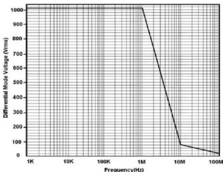
Appendix 1 Max. Differential Mode Voltage vs Freq.
line
| Frequency(Hz) | Differential Mode Voltage (Vrms) | | ------------- | -------------------------------- | | 1K | 1000 | | 10K | 1000 | | 100K | 1000 | | 1M | 1000 | | 10M | 100 | | 100M | 0 |Figure 5 PHA0150/PHA1150/PHA2150 Max. Differential Mode Voltage vs Freq.
Appendix 2 Package List
This section lists the standard accessories of the PHA series probe.
Table 1 Standard Accessories of the PHA Series Probe
| Name | Specification | Qty. |
| Probe Body | PHA0150/PHA1150/PHA2150 | 1 |
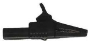
| Alligator Clip | CAT II 1000 VCAT III 600 V | 1 Pair(red/black) |
| Insulated PlungerHook Clip | - | 1 Pair(red/black) |
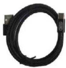
| USB Type-C Cable | 1 m | 1 |
| User Guide | - | 1 |
| Warranty Card | - | 1 |
Accessories
natural_image
Black mechanical tool with a handle and textured grip (no visible text or symbols)Alligator Clip
natural_image
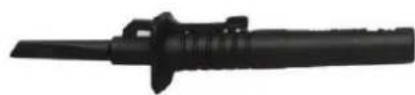
Black mechanical component with cylindrical shaft and flanged end (no visible text or symbols)Insulated Plunger Hook Clip
natural_image
Coiled black cable with connectors, no visible text or symbolsUSB Type-C Cable
Appendix 3 Warranty
RIGOL TECHNOLOGIES CO., LTD. (hereinafter referred to as RIGOL) warrants that the product will be free from defects in materials and workmanship within the warranty period. If a product proves defective within the warranty period, RIGOL guarantees free replacement or repair for the defective product.
To get repair service, please contact with your nearest RIGOL sales or service office.
There is no other warranty, expressed or implied, except such as is expressly set forth herein or other applicable warranty card. There is no implied warranty of merchantability or fitness for a particular purpose. Under no circumstances shall RIGOL be liable for any consequential, indirect, ensuing, or special damages for any breach of warranty in any case.
- RIGOL
- User Guide
- PHA High-Voltage Differential Probe
- Guaranty and Declaration
- Copyright
- Trademark Information
- Publication Number
- Notices
- Product Certification
- Contact Us
- General Safety Summary
- CAUTION
- Safety Terms and Symbols
- Safety Precautions
- Contents
- General Inspection
- Inspect the packaging
- Check the probe
- Check the accessories
- Main Features
- Measurement Scenarios
- Probe Components
- Probe Component Description
- ● High-Voltage Differential Input Cable
- ● Max. Differential Mode Input Voltage
- • Overrange Indicator
- • Attenuation Switchover Button
- ● Bandwidth Switchover Button
- ● Audible Overrange Alarm On/Off Button
- - Load Impedance
- - USB Power Interface
- - Output Interface
- To Use the Probe
- Preparation for Measurement
- Measurement Steps
- Precautions During Measurement
- Failures and Troubleshooting
- Specifications
- Technical Specifications
- Appendix
- Appendix 1 Max. Differential Mode Voltage vs Freq.
- Appendix 2 Package List
- Appendix 3 Warranty
Marke : Rigol
Modell : PHA0150
Kategorie : Nicht kategorisiert