
162470 - Netzwerk-Patchfeld Intellinet - Kostenlose Bedienungsanleitung
Finden Sie kostenlos die Bedienungsanleitung des Geräts 162470 Intellinet als PDF.


| Produkttyp | Netzwerkgerät |
| Modell | 162470 |
| Marke | Intellinet |
| Abmessungen (ca.) | 20 x 15 x 5 cm |
| Gewicht (ca.) | 0,5 kg |
| Stromversorgung | 5V DC über Netzteil |
| Leistungsaufnahme | 5 W (max.) |
| Hauptfunktionen | Datenübertragung, Signalverstärkung, Netzwerkverbindung |
| Anschlüsse | 1x RJ45, 1x USB (falls zutreffend) |
| Betriebstemperatur | 0 °C bis 40 °C |
| Lagertemperatur | -20 °C bis 60 °C |
| Luftfeuchtigkeit | 10% bis 90% (nicht kondensierend) |
| Gehäusematerial | Kunststoff |
| Farbe | Schwarz |
| Montage | Tischaufstellung oder Wandmontage (optional) |
| Reinigung | Mit trockenem, fusselfreiem Tuch reinigen. Keine Flüssigkeiten verwenden. |
| Sicherheitshinweise | Nicht öffnen, vor Feuchtigkeit schützen, Netzteil nur im Trockenen verwenden. |
| Reparatur | Reparaturen nur durch qualifiziertes Fachpersonal. |
| Mitgeliefertes Zubehör | Netzteil, Bedienungsanleitung |
| Garantie | 2 Jahre |
Häufig gestellte Fragen - 162470 Intellinet
Benutzerfragen zu 162470 Intellinet
0 Frage zu diesem Gerät. Beantworten Sie die, die Sie kennen, oder stellen Sie Ihre eigene.
Eine neue Frage zu diesem Gerät stellen
Laden Sie die Anleitung für Ihr Netzwerk-Patchfeld kostenlos im PDF-Format! Finden Sie Ihr Handbuch 162470 - Intellinet und nehmen Sie Ihr elektronisches Gerät wieder in die Hand. Auf dieser Seite sind alle Dokumente veröffentlicht, die für die Verwendung Ihres Geräts notwendig sind. 162470 von der Marke Intellinet.
BEDIENUNGSANLEITUNG 162470 Intellinet
WALL MOUNT
PATCH PANEL
QUICK
START
GUIDE
Thank you for purchasing this INTELLINET NETWORK SOLUTIONS ^® Wall Mount Patch Panel.
Follow the steps on this quick start guide for easy installation and use of either the Cat5e or Cat6 version of this product.

12-port Cat5e UTP model shown
IDC (3 options)




110D type



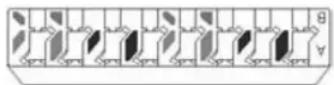
Krone type
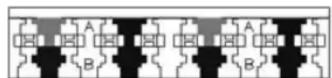



110D & Krone
IDC compatible

- Carefully strip away approximately 30 mm of the cable jacket(s) (above left) to be connected to the Patch Panel, separating the wires into four pairs. Using a wire cutter, cut the wire holder (above right) flush with the cable jacket.

T568A
PIN 5 WHITE/BLUE
PIN 4 BLUE
PIN 1 WHITE/GREEN
PIN 2 GREEN
PIN 3 WHITE/ORANGE
PIN 6 ORANGE
PIN 7 WHITE/BROWN
PIN 8 BROWN
T568B
PIN 5 WHITE/BLUE
PIN 4 BLUE
PIN 1 WHITE/ORANGE
PIN 2 ORANGE
PIN 3 WHITE/GREEN
PIN 6 GREEN
PIN 7 WHITE/BROWN
PIN 8 BROWN

natural_image
Close-up of a sewing machine needle stitching a printed circuit board (no visible text or symbols)- Follow the IDC color-code chart above to position the wires, then use a Krone punch-down tool to crimp and connect them.

INTELLINET
BRINGING NETWORKS TO LIFE
www.intellinet-network.com
Are you completely satisfied with this product?
Please contact your
INTELLINET NETWORK SOLUTIONS™
dealer with comments or questions.
Copyright © INTELLINET NETWORK SOLUTIONS
All products mentioned are trademarks or registered trademarks
of their respective owners.


Marke : Intellinet
Modell : 162470
Kategorie : Netzwerk-Patchfeld