
UT58E - Multimeter Uni-T - Kostenlose Bedienungsanleitung
Finden Sie kostenlos die Bedienungsanleitung des Geräts UT58E Uni-T als PDF.


| Produkttyp | Digitalmultimeter |
| Modell | UT58E |
| Marke | Uni-T |
| Anzeige | 20000 Counts, große LCD |
| Gleichspannungsbereiche | 200 mV, 2 V, 20 V, 200 V, 1000 V |
| Wechselspannungsbereiche | 2 V, 20 V, 200 V, 1000 V |
| Gleichstrombereiche | 2 mA, 200 mA, 20 A |
| Wechselstrombereiche | 20 mA, 200 mA, 20 A |
| Widerstandsbereiche | 200 Ω, 2 kΩ, 20 kΩ, 2 MΩ, 200 MΩ |
| Kapazitätsbereiche | 2 nF, 20 nF, 2 µF, 20 µF |
| Frequenzbereich | 20 kHz |
| Temperaturbereich | -40 °C bis 1000 °C |
| Transistortest | hFE (0–1000β) |
| Diodentest und Durchgangsprüfung | Ja |
| Spannungsfestigkeit | CAT II 1000 V, CAT III 600 V |
| Schutzart | Doppelisolierung gemäß IEC61010 |
| Stromversorgung | 1 x 9 V Blockbatterie (NEDA1604, 6F22 oder 006P) |
| Abmessungen | 179 x 88 x 39 mm |
| Gewicht | ca. 380 g (inkl. Holster und Batterie) |
| Lieferumfang | Messleitungen, Multifunktionsbuchse, Prüfklemmen, Temperaturfühler, Holster, Batterie, Bedienungsanleitung |
| Besondere Funktionen | Datenhaltung (Hold), Sleep-Modus (15 Min.), Überlastschutz für alle Bereiche |
| Reinigung und Pflege | Feuchtes Tuch und mildes Reinigungsmittel, keine Lösungsmittel |
| Sicherung | 0,5 A / 250 V flink (5x20 mm) für mA-Eingang und 0,63 A / 250 V flink (5x20 mm) für VΩ°C-Eingang |
| Zubehör und Ersatzteile | Nur baugleiche Sicherungen und Batterien verwenden |
Häufig gestellte Fragen - UT58E Uni-T
Benutzerfragen zu UT58E Uni-T
0 Frage zu diesem Gerät. Beantworten Sie die, die Sie kennen, oder stellen Sie Ihre eigene.
Eine neue Frage zu diesem Gerät stellen
Laden Sie die Anleitung für Ihr Multimeter kostenlos im PDF-Format! Finden Sie Ihr Handbuch UT58E - Uni-T und nehmen Sie Ihr elektronisches Gerät wieder in die Hand. Auf dieser Seite sind alle Dokumente veröffentlicht, die für die Verwendung Ihres Geräts notwendig sind. UT58E von der Marke Uni-T.
BEDIENUNGSANLEITUNG UT58E Uni-T
UT58E
Operating Manual
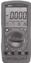
Modern Digital Multimeter
Overview
Warning
To avoid electric shock or personal injury, read the "Safety Information carefully before using the Meter.
Digital Multimeter Model UT58E is a 20000-count hand -held instrument with remarkable features: ex-large LCD, steady operations, overload protection for all ranges and unique structure. It is designed with large -scale integrated circuits and dual integral A/D converter as the core, which offers 28 measuring ranges and can measure AC/DC voltage, AC/DC current, resistance, capacitance, transistor, diode and continuity. It is also equipped with data hold, full icon display and sleep mode functions, etc;
Unpacking Inspection
Open the package case and take out the Meter. Check the following items carefully for any missing or damaged part:
| Item | Description | Qty |
| 1 | English Operating Manual | 1 pc |
| 2 | Test Lead | 1 pair |
| 3 | Multi-Purpose Socket | 1 pc |
| 4 | Test Clip | 1 pair |
| 5 | Point Contact Temperature Probe | 1 pc |
| 6 | Holster | 1 pc |
| 7 | 9V Battery (NEDA 1604, 6F22 or 009P) | 1 pc |
In the event you find any missing or damaged part, please contact your dealer immediately.
Safety Information
This Meter complies with the standard IEC61010: Pollution Degree 2; Overvoltage Category (CAT. II 1000V, CAT. III 600V) and Double Insulation.
CAT. II: Local level, appliance, PORTABLE EQUIPMENT etc., with smaller transient voltage overvoltages than CAT. III
CAT. III: Distribution level, fixed installation, with smaller transient overvoltages than CAT. IV
Use the Meter only as specified in this operating manual otherwise the protection provided by the Meter may be impaired.
In this manual, a Warning identifies conditions and actions that pose hazards to the user, or may damage the Meter or the equipment under test.
A Note identifies the information that user should pay attention to.
Warning
To avoid possible electric shock or personal injury, and to avoid possible damage to the Meter or to the equipment under test, adhere to the following rules:
- Before using the Meter inspect the case. Do not use the Meter if it is damaged or the case (or part of the case) is removed. Look for cracks or missing plastic. Pay attention to the insulation around the connectors.
- Inspect the test leads for damaged insulation or exposed metal. Check the test leads for continuity. Replace damaged test leads with identical model number or electrical specifications before using the Meter.
- Do not apply more than the rated voltage, as marked on the Meter, between the terminals or between any terminal and grounding.
- The rotary switch should be placed in the right position and no any changeover of range shall be made during measurement to prevent damage of the Meter.
- When the Meter works at an effective voltage over 60V in DC or 30V rms in AC, special care should be taken for there is danger of electric shock.
- Use the proper terminals, function, and range for your measurements.
- If the value to be measured is unknown, use the maximum measurement position and reduce the range stop by step until a satisfactory reading is obtained.
- Do not use or store the Meter in an environment of high temperature, humidity, explosive, inflammable and strong magnetic field. The performance of
the Meter may deteriorate after dampened.
- When using the test leads, keep your fingers behind the finger guards.
- Disconnect circuit power and discharge all high -voltage capacitors before testing resistance, continuity, diodes, capacitance or current.
- Before measuring current, check the Meter's fuses and turn off power to the circuit before connecting the Meter to the circuit.
- Replace the battery as soon as the battery indicator 📋appears. With a low battery, the Meter might produce false readings that can lead to electric shock and personal injury.
- Remove testads and multi-purpose socket from the Meter and turn the Meter power off before opening the Meter case.
- When servicing the Meter, : use the replacement parts with the same model or identical electrical specifications.
- To avoid any damage to the meter or any accident, do not alter the internal circuit of the Meter randomly. - Soft cloth and mild detergent should be used to clean the surface of the Meter when servicing.
No abrasive and solvent should be used to prevent the surface of the Meter from corrosion, damage and accident.
● The Meter is suitable for indoor use.
- Turn the Meter power off when it is not in use and take out the battery when not using for a long time.
- Constantly check the battery as it may leak when it has been using for some time, replace the battery as soon as leaking appears. A leaking battery will damage the Meter.
International Electrical Symbols
| AC (Alternating Current). | |
| DC (Direct Current). | |
| Grounding. | |
| Double Insulated. | |
| Low Battery Indication. | |
| Warning. Refer to the Operating Manual. | |
| Diode. | |
| Fuse. | |
| Continuity Test. | |
| Conforms to Standards of European Union |
The Meter Structure (See Figure 1)
① LCD Display
② HOLD Button.
③ Rotary Switch
④ COM Input Terminal
⑤ POWER
© POWER © Other Inc
⑥ Other input terminal.
⑦ MA input terminal
⑧ 20A Input Terminal
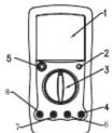
(Figure 1)
Rotary Switch
Below table indicated for information about the rotary switch positions.
| Rotary Switch Position | Function |
| V ... | DC voltage measurement. |
| V | AC voltage measurement. |
| hFE | Transistor Test |
| A | AC Current Measurement |
| A ... | DC Current Measurement |
| Fcx Capacitance Test | |
| °C Temperature Measurement | |
| Hz | Frequency Measurement |
| → | Diode test |
| Continuity test | |
| Ω | Resistance measurement. |
Functional Buttons
Below table indicated for information about the functional button operations
| Button | Description |
| POWER(Yellow Button) | Turn the Meter on and off.Press down the POWER to turn on the Meter.Press up the POWER to turn off the Meter. |
| HOLD(Blue Button) | Press HOLD once to enter hold mode.Press HOLD again to exit hold mode.In Hold mode, [1] is displayed and the present value is shown. |
Display Symbols (See Figure 2)
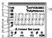
(Figure 2)
| No. | Symbol | Description |
| 1 | The battery is low⚠ Warning: To avoid false readings, replace the battery as soon as the battery indicator appears. | |
| 2 | Warning Symbol. | |
| 3 | AC | Indicator for AC voltage or current. The displayed value is the mean value. |
| 4 | Indicates negative reading. | |
| 5 | Test of diode. | |
| 6 | The continuity buzzer is on. | |
| 7 | Date hold is active. | |
| 8 | Connect Terminal | Indicator of connecting test leads into different input terminals. |
| 9 | hFE | The Unit of Transistor Test |
| 10 | mV, V | V: Volts. The unit of voltage. mV: Millivolt. 1 × 10^3 or 0.001 volts. |
| Ω, kΩ, MΩ | Ω: Ohm. The unit of resistance, kΩ: kilohm. 1 × 10^3 or 1000 ohms. MΩ: Megaohm. 1 × 10^6 or 1,000,000 ohms. | |
| μA, mA, A | A: Amperes (amps). The unit of current. mA: Milliamp. 1 × 10^-3 or 0.001 amperes. μA: Microamp. 1 × 10^-4 or 0.000001 amperes. | |
| °C, F | °C: Centigrade temperature °F: Fahrenheit temperature | |
| kHz | Hertz. The unit of frequency in cycles/second. Kilohertz. 1 × 10^-3 or 1,000 hertz. | |
| nF, μF | F: Farad. The unit of capacitance. μF: Microfarad. 1 × 10^-6 or 0.000001 farads. nF: Nanofarad. 1 × 10 br0.000000001 farads. |
Measurement Operation
A. Measuring DC and AC Voltage (See Figure 3)
Warning
To avoid harms to you or damages to the Meter from electric shock, never attempt to measure voltages higher than 1000 or 1000V rms although readings may be obtained.
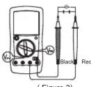
The DC Voltage ranges are: 200mV 2V, 20V, 200V and 1000V
The AC Voltage ranges are: 2V, 20V, 200V and 1000V
To measure DC&ACVoltage, connect the Meter as follows:
- Insert the red test lead into the VΩ input terminal
and the black test lead into the COM input terminal. - Set the rotary switch to an appropriate measurement position in V or V range
- Connect the test leads ss with the object to be
measured in parallel.
The measured value shows on the display.
Note
- If the value of voltage to be measured is unknown, use the maximum measurement position (1000V) and reduce the range step by step until a satisfactor reading is obtained.
- The LCD displays "1" indicating the existing select range is overloaded, it is required to select a higher range in order to obtain a correct reading.
- In each range, the Meter has an input impedance of approx. 10M This loading effect can cause measurement errors in high impedance circuits. If thd circuit impedance is less than or equal to 10k , the error is negligible (0.1% or less).
- When voltage measurement has been completed disconnect the connection between the testing leads and the circuit under test, and remove the testing leads away from the input terminal of the Meter.
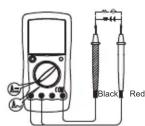
B. Measuring DC and AC Current (See Figure 4)
(Figure 4)
Warning
Never attempt an in-circuit current measurement where the open circuit voltage between terminals and ground is greater than 60V DC or 30V rms in AC.
If the fuse burns out during measurement, the Meter may be damaged or the operator himself may be hurt. Use proper terminals, function, and range for the measurement. When the testing leads are connected to the current terminals, do not parallel them across any circuit.
The DC Current ranges: 2mA, 200mA and 20A
The AC Current ranges: 20mA, 200mA and 20A
To measure current, do the following:
-
Turn off power to the circuit. Discharge all high-voltage capacitors.
-
Insert the red test lead into the 20A or mA input terminal and the black test lead into the COM terminal. When you measure current below 200mA , please insert the red test lead into the mA input terminal. When you measure 200mA or above, insert the red test lead into the 20A input terminal.
-
Set the rotary switch to an appropriate measurement position in A==or A\~range.
-
Break the current path to be tested. Connect the red test lead in serial to the more positive side of the break and the black test lead to the more negative side of the break.
-
Turn on power to the circuit.
The measured value shows on the display.
Note
- If the value of current to be measured is unknown, use the maximum measurement position, and reduce the range step by step until a satisfactory reading is obtained.
- For safety sake, the measuring time for high current should be less than 10 seconds and the interval time between 2 measurements should be greater than 15 minutes
- When current measurement has been completed, disconnect the connection between the testing leads and the circuit under test, and remove the testing leads away from the input terminal of the Meter.
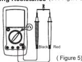
C. Measuring Resistance (See Figure 5)
Warning
To avoid damages to the Meter or to the devices under test, disconnect circuit power and discharge all the high-voltage capacitors before measuring resistance.
The resistance ranges are: 200 Ω, 2kΩ, 20kΩ, 2MΩ and 200MΩ
To measure resistance, connect the Meter as follows: 1. Insert the red test lead into the V input terminal and the black test lead into the COM terminal.
-
Set the rotary switch to an appropriate measurement position in range.
-
Connect the test lead with the object being measured in parallel.
The measured value shows on the display.
Note
- The test leads can add 0.1 to 0.3 of error to the slow-resistance(200Ω) measurement.
- For high resistance(>1MΩ), it is normal taking several seconds to obtain a stable reading..
- When there is no input, for example in open circuit condition, the Meter displays "1".
- When resistance measurement has been completed, disconnect the connection between the testing leads and the circuit under test, and remove the testing leads away from the input terminal of the Meter.
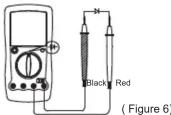
D. Testing Diodes and Continuity (See Figure 6)
Warning
To avoid damage to the Meter or to the equipment under test, disconnect circuit power and discharge all high-voltage capacitors before measuring diodes. To avoid harms to you, never attempt to input voltages higher than 60V DC or 30V rms in AC
Measuring Diodes
Use the diode test to check diodes, transistors, and other semiconductor devices. The diode test sends a current through the semiconductor junction, and then measures the voltage drop across the junction. A good silicon junction drops between 0.5V and 0.8V
To test out a diode out of a circuit, connect the Meter as follows:
-
Insert the red test lead into the vΩ input terminal and the black test lead into the COM terminal
-
Set the rotary switch to →→
-
For forward voltage drop readings on any semiconductor component, place the red test lead on the component's anode and the black test lead on the component's cathode.
The measured value shows on the display
Note
● In a circuit, a good diode should still produce a forward
voltage drop reading of 0.5V to 0.8V; however; the reverse voltage drop reading can vary depending on the resistance of other pathways between the probe tips.
- Connect the test leads to the proper terminals as said above to avoid error display. The LCD will display"1" indicating open-circuit or wrong connection. The unit of diode is Volt (V), displaying the positive-connection voltage-drop value.
● The open-circuit voltage is around 2.8V. - When diode testing has been completed, disconnect the connection between the testing leads and the circuit under test, and remove the testing leads away from the input terminal of the Meter.
Testing for Continuity
To test for continuity, connect the Meter as below:
1. Insert the red test lead into VΩ terminal and the black test lead into the COM terminal.
2. Set the rotary switch to ⏚-
3. Connect the test leads across with the object being measured
4. The buzzer sounds if the resistance of a circuit under test is ≤slant70
The tested circuit resistance value shows on the display and the unit is .
Note
- When continuity testing has been completed, disconnect the connection between the testing leads and the circuit under test, and remove the testing leads away from the input terminal of the Meter.
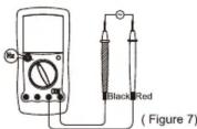
E. Measuring Frequency (See Figure 7)
Warning
To avoid harms to you, never attempt to input voltages higher than 60V DC or 30V rms in AC. When the voltage of tested frequency signal is higher than 30V rms, the measuring accuracy may not be guaranteed.
The frequency measurement range is 20kHz. To measure frequency, connect the Meter as follows:
- Insert the red test lead into the VΩ terminal and the black test lead into the COM terminal.
- Set the rotary switch to 20kHz range
- Connect the test leads with the object being measured in parallel.
The measured value shows on the display.
Note
- When Hz measurement has been completed, disconnect the connection between the testing leads and the circuit under test, and remove the testing leads away from the input terminals of the Meter.
F. Measuring Temperature (See Figure 8)
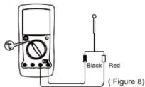
Warning
To avoid harm to you or damages to the Meter, never attempt to measure voltages higher than 60V in DC or 30V rms in AC although readings may be obtained. During testing, the operating temperature must be within 18-23°C, otherwise the obtained reading may not be correct especially measuring low temperature. The temperature measurement range is from -40°C\~1000°C To measure temperature, connect the Meter as follows:
- Insert the "+" and "-" temperature probe into corresponding VΩ and COM terminal.
- Set the rotary switch to ^ C
- Place the temperature probe's tip to the object being measured.
The measured value shows on the display.
Note
- When the temperature probe doesn't insert into the
Meter. LCD displays internal temperature of the Meter. - The supplied temperature probe can measure only up to 250°C. If high temperature measurement is required, please purchase the temperature probe of other models from our company.
- When temperature measuremnet has been completed remove the temperature probe away from the input terminal of the Meter.
G. Measuring Capacitance (See Figure 9)
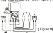
Warning
To avoid damage to the Meter or to the equipment under test, disconnect circuit power and discharge all high-voltage capacitors before measuring capacitance. Use the DC voltage function to confirm that the capacitor is discharged.
To avoid harms to you, never attempt to input voltages
The capacitance ranges: 2nF, 20nF, 2μF and 20 μ F. To measure capacitance, connect the Meter as follows:
-
According to the size of the tested object's leads, select multi-purpose socket or test clip to insert into the mA and VΩ terminal.
-
Set the rotary switch to an appropriate measurement position in Fcx range.
- Insert the tested object into the corresponding jack of the multi-purpose socket or connect the test clip to the object being measured.
The measured value shows on the display.
Note
- If the value of capacitance to be measured is unknown, use the maximum measurement position, and reduce the range step by step until a satisfactory reading is obtained.
- When the tested capacitor is shorted or the capacitor value is overloaded, the LCD display "1".
- To minimize the measurement error caused by the distributed capacitance, the testing lead should be as short as possible.
- To increase the accuracy especially when measuring small capacitance range, subtract the test leads' open-circuit value from the display reading.
- It is normal to take a longer time when testing a high capacitor value.
- For testing the capacitor with polarity, connect the red clip or red test lead to anode and black clip or black test lead to cathode.
- It takes some time for zeroing when you switching over the rotary switch, the floating readings showing on the display during this process do not affect the final testing accuracy.
- When capacitance testing has been completed, disconnect tested objects from multi-purpose socket or test clip, and remove multi-purpose socket or test clip away from the input terminal of the Meter.
H. Measuring Transistor (See Figure9)
Warning
To avoid harms to you, please do not attempt to input voltages higher than 60V DC or 30V rms AC.
To measure transistor, connect the Meter as follows:
- Insert the multi-purpose socket into the VΩ and mA terminal.
- Set the rotary switch to hFE range.
- Insert the NPN or PNP type transistor to be tested into the corresponding jack of the multi-purpose socket The measured nearest transistor value shows on the display.
Note
- When transistor measurement has been completed, remove the transistor to be tested away from the multi-purpose socket, and remove multi-purpose socket away from the input terminal of the Meter.
Sleep Mode
To preserve battery life, the Meter automatically turns off if you do not turn the rotary switch or press any button for around 15 minutes. When the Meter is under sleep mode, it consumes 10 A current.
To activate the Meter, press POWER for two times
Operation of Hold Mode
Warning
To avoid possibility of electric shock, do not use Hold mode to determine if circuits are without power. The Hold mode will not capture unstable or noisy readings.
To use the Hold mode as follows:
- Press HOLD to enter Hold mode.
- Press HOLD again to exit Hold mode.
- In Hold mode, H is displayed.
General Specifications
● Maximum Voltage between any Terminals and grounding: Refer to different range input protection voltage.
- Fused Protection for
mA Input Terminal : CE Version: 0.5A, 250V fast type, φ5x20mm. V Ω°C input jack's fuse: 0.63A, 250V fast type, 5×20mm, to be used on capacitance, temperature and transistor testing input protection.
20A Input Terminal
● Maximum Display
- Range
- Polarity display
- Overloading
● Low Battery Indication
- Data Hold
● Temperature: Operating: 0^ C\~ 40^ C( 32^ F\~ 104^ F); Storage: -10^ C\~ 50^ C( 14^ F\~ 122^ F).
● Relative Humidity
≤slant 50% @30^ 40^
● Altitude: Operating
- Electromagnetic Compatibility: In a radio field of 1 V/m, Overall Accuracy = Specified Accuracy + 5% of Range; in a radio field of more than 1 V/m, no assigned accuracy is specified.
● Battery Type
•
- Dimensions
● Weight
● Safety/Compliances
: Unfused.
: 19999, updates 2\~3
times/second.
: Manual ranging.
: Automatically
: Display "1".
: Display " ☐"
: Display" H"
: 0°C\~40°C(32°F\~104°F);
Storage: -10°C\~50°C(14°F\~122°F).
≤75% @ 0°C\~ below 30°C;
≤50% @ 30 °C\~40°C
2000m; Storage: 10000m.
ty: In a radio field of 1 V/m,
d Accuracy + 5% of Range:
1 V/m, no assigned
1 V/m, No assigned
One piece of 9V (NEDA1604
or 6F22 or 006P)
179x88x39mm
Approx.380g (including
holster and battery)
IEC61010 CAT II 1000V.
CATIII 600V Overvoltage,
Double Insulation
standards
CE
- Certificate:
Accuracy Specifications
Accuracya:±(% reading + b digits),guarantee for 1 year.
Operating temperature:18°C\~28°C.
Relative humidity: ≤ 75%RH
A. DC Voltage
| Range | Resolution | Accuracy | Overload Protection |
| 200mV | 0.01mV | ±(0.05%+3) | 250V DC / V AC |
| 2V | 0.0001V | ±(0.1%+3) | 1000V rms |
| 20V | 0.001V | ||
| 200V | 0.01V | ||
| 1000V | 0.1V | ±(0.15%+5) |
Remarks: Input Impedance: approx.10MΩ
B. AC Voltage
| Range | Resolution | Accuracy | Overload Protection |
| 2V | 0.0001V | ±(0.5%+10) | 1000V rms |
| 20V | 0.001V | ||
| 200V | 0.01V | ||
| 1000V | 0.1V | ±(1%+10) |
Remarks:
● Input Impedance: approx.2M Ω
● Frequency response: 40Hz\~400Hz
● Displays sinewave RMS value(AVG response)
C. DC Current
| Range | Resolution | Accuracy | Overload Protection |
| 2mA | 0.0001mA | ±(0.5%+5) | CE Version:Fuse 0.5A, 250V, fast type, 5 × 20 mm |
| 200mA | 0.01mA | ±(0.8%+5) | |
| 20A | 0.001A | ±(2%+10) | Un-Fused |
Remarks:
- At 20A Range:
Continuous measurement≤10 seconds and interval
time between 2 measurement greater than 15 minutes
● Measuring Voltage Drop: 200mV for full ranges.
D. AC Current
| Range | Resolution | Accuracy | Overload Protection |
| 20mA | 0.001mA | ±(0.8%+10) | CE Version:Fuse 0.5A, 250V, fast type, 5 × 20 mm |
| 200mA | 0.01mA | ±(1.2%+10) | |
| 20A | 0.001A | ±(2.5%+10) | Un-Fused |
Remarks:
● Frequency response: 40Hz\~400Hz
- At 20A Range:
Continuous measurement ≤slant 10 seconds and interval time between 2 measurement greater than 15 minutes
● Measuring Voltage Drop: 200mV for full ranges
● Displays sinewave RMS value(AVG response)
E. Resistance
| Range | Resolution | Accuracy | Overload Protection |
| 200Ω | 0.01Ω | ±(0.5%+10) + Test Lead Short Circuit Resistance | 250V rms |
| 2kΩ | 0.0001kΩ | ||
| 20kΩ | 0.001kΩ | ±(0.3%+1) | |
| 2MΩ | 0.0001MΩ | ||
| 200MΩ | 0.01MΩ | ±5%(reading-1000)+10) |
Remarks:
- At 200MΩ range, the test leads are shorted and the displayed value is 1000 digits. To ensure the accuracy, please subtract this value from the display reading.
- To obtain accurate readings when measuring 200 short-circuit the testing leads beforehand and record the reading obtained (called this reading as X). (X) is the additional resistance from the test lead. Then use the equation:
measured resistance value (Y) - (X) = accurate
readings of resistance
F. Diodes and Continuity
| Function | Range | Resolution | Overload Protection | Remarks |
| Diodes | 0.1mV | 250V rms | Open circuit voltage approx 2.8 v | |
| Continuity Test | 0.1Ω | The buzzer sounds if the resistance of a circuit under test is ≤slant 70Ω |
G.Frequency
| Range | Resolution | Accuracy | Overload Protection | Sensitivity |
| 20kHz | 1Hz | ±(1.5%+5) | 250V rms | ≤200mV |
H.Temperature
| Range | Resolution | Accuracy | Overload Protection |
| -40°C~0°C | 1°C | ±(3%+70) | 250V rms |
| 0°C~400°C | ±(1%+30) | ||
| 400°C~1000°C | ±(2%+50) |
I. Capacitance
| Range | Resolution | Accuracy | Overload Protection |
| 2nF | 0.0001nF | ±(3%+40) | 250V rms |
| 20nF | 0.001nF | ±(4%+10) | |
| 2μF | 0.0001μF | ||
| 20μF | 0.001μF |
Remarks:
● Testing signal is approx.: 400Hz 40mVrms
J. Transistor
| Range | Resolution | Remarks | Testing Conditions | Overload Protection |
| hFE | 1β | The display value is the tested transistor (NPN, PNP) nearest value of hFE (0~1000β) | Ibo ≈ 10μAVce ≈ 2.8V | 250V rms |
Maintenance
This section provides basic maintenance information
including battery and fuse replacement instruction.
Warning
Do not attempt to repair or service your Meter unless
you are qualified to do so and have the relevant
calibration, performance test, and service information.
To avoid electrical shock or damage to the Meter, do
not get water inside the case.
A. General Service
- Periodically wipe the case with damp cloth and mild
detergent. Do not use chemical solvent.
● To clean the terminals with cotton bar with detergent,
as dirt or moisture in the terminals can affect readings
● Turn the Meter off when it is not in use and take out
the battery when not using for a long time.
- Do not store the Meter in place of humidity, high
temperature, explosive, inflammable and strong
magnetic field
B. Replacing the Fuses (See Figure 10)
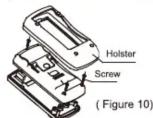
Warning
To avoid electrical shock or arc blast, or personal
injury or damage to the Meter, use specified fuses
ONLY in accordance with the following procedure
To replace the Meter's fuse:
- Turn the Meter off and remove all connections from
the terminals.
-
Remove the holster from the Meter.
-
Remove the 3 screws from the case bottom, and
separate the case top from the case bottom.
- Remove the fuse by gently prying one end loose,
then take out the fuse from its bracket.
- Install ONLY replacement fuses with the identical type
and specification and make sure the fuse is fixed firmly
in the bracket.
Fuse 1: 0.5A, 250V, fast type, 5x20mm
Fuse 2: 0.63A, 250V, fast type, 5x20mm
- Rejoin the case bottom and case top, and reinstall the
3 screws and holster.
Replacement of the fuses is seldom required. Burning
of a fuse always results from improper operation.
C. Replacing the Battery (See Figure 10)
Warning
To avoid false readings, which could lead to possible
electric shock or personal injury, replace the battery
as soon as the battery indicator "也" appears.
To replace the Meter's battery:
- Turn the Meter power off and remove all connections
from the terminals.
- Remove the holster from the Meter
- Remove the 3 screws from the case bottom, and
separate the case top from the case bottom. - Remove the battery from the battery connector.
- Replace with a new 9V battery (NEDA1604, 6F22 or
006P). - Rejoin the case bottom and case top, and reinstall the 3 screws and the holster.
** END **
This operating manual is subject to change without notice.
UNI-T.
UNI-TREND TECHNOLOGY (CHINA) CO., LTD.
No6, Gong Ye Bei 1st Road.
Songshan Lake National High-Tech Industrial
Development Zone, Dongguan City, Guangdong Province, China
Guangdong Province, Ch
Tel: (86-769) 8572 3888
http://www.uni-trend.com
广力云智慧零售收银系统


- Modern Digital Multimeter
- Overview
- Warning
- Unpacking Inspection
- Safety Information
- Rotary Switch
- Functional Buttons
- Measurement Operation
- Note
- Measuring Diodes
- Testing for Continuity
- Measuring Transistor (See Figure9)
- Sleep Mode
- Operation of Hold Mode
- Accuracy Specifications
- Remarks:
- Maintenance
- UNI-T.
Marke : Uni-T
Modell : UT58E
Kategorie : Multimeter