
DC-S2 - Système de contrôle d'accès sécurisé BLAUPUNKT - Kostenlose Bedienungsanleitung
Finden Sie kostenlos die Bedienungsanleitung des Geräts DC-S2 BLAUPUNKT als PDF.


| Produkttyp | Zugangskontrollsystem |
| Modell | DC-S2 |
| Marke | Blaupunkt |
| Abmessungen (ca.) | 100 x 50 x 20 mm |
| Gewicht (ca.) | 150 g |
| Stromversorgung | 12 V DC (Netzteil) oder 4 x AA-Batterien (optional) |
| Stromverbrauch | Standby: < 50 mA, Aktiv: < 200 mA |
| Zugangsmedien | RFID-Karten (13,56 MHz), Code-Eingabe über Tastatur |
| Benutzerkapazität | bis zu 500 Benutzer |
| Reichweite RFID | bis zu 5 cm |
| Anzeige | LED-Statusanzeige (rot/grün) |
| Schutzklasse | IP54 (spritzwassergeschützt) |
| Betriebstemperatur | -10 °C bis +50 °C |
| Installation | Wandmontage mit Schrauben und Dübeln |
| Anschlüsse | Klemmen für Türöffner, AUX, Netzteil |
| Programmierung | über Mastercode oder PC-Software (optional) |
| Funktionen | Einzel- und Gruppenberechtigung, Zeitfenster, Protokollierung |
| Reinigung | mit weichem, trockenem Tuch; keine aggressiven Reiniger |
| Sicherheit | Manipulationsschutz, Code-Sperre nach Fehleingaben |
| Ersatzteile & Reparatur | Ersatzteile über Fachhandel; Reparatur durch autorisierte Stellen |
| Lieferumfang | Bedienfeld, Montagematerial, Kurzanleitung |
Häufig gestellte Fragen - DC-S2 BLAUPUNKT
Benutzerfragen zu DC-S2 BLAUPUNKT
0 Frage zu diesem Gerät. Beantworten Sie die, die Sie kennen, oder stellen Sie Ihre eigene.
Eine neue Frage zu diesem Gerät stellen
Laden Sie die Anleitung für Ihr Système de contrôle d'accès sécurisé kostenlos im PDF-Format! Finden Sie Ihr Handbuch DC-S2 - BLAUPUNKT und nehmen Sie Ihr elektronisches Gerät wieder in die Hand. Auf dieser Seite sind alle Dokumente veröffentlicht, die für die Verwendung Ihres Geräts notwendig sind. DC-S2 von der Marke BLAUPUNKT.
BEDIENUNGSANLEITUNG DC-S2 BLAUPUNKT
Wireless Door Contact (DC-S2)
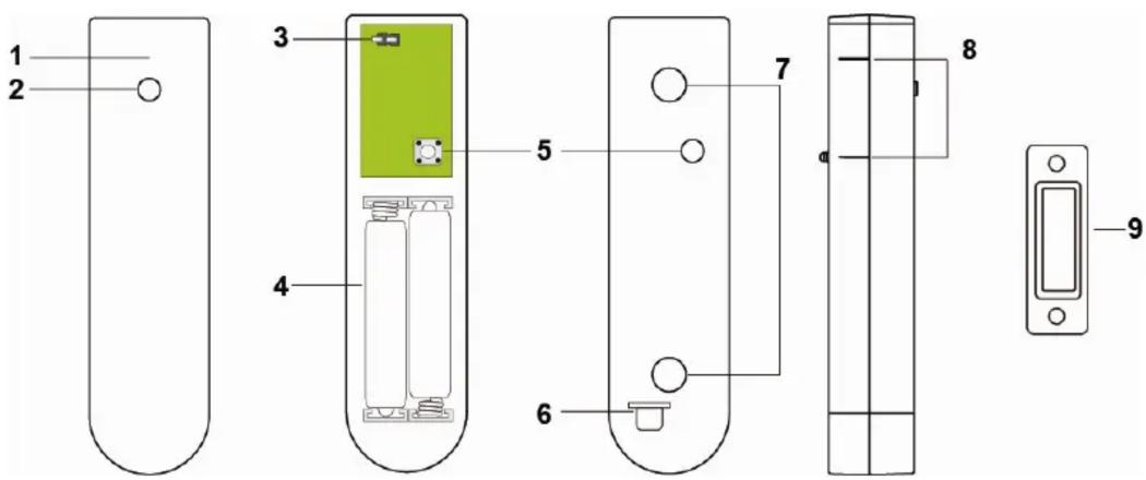
Parts Description
- LED indicator (Inside)
- Learn/Test Button
Press the button to transmit a learn/test code and enter Test mode for 3 minutes. The LED will light up whenever Door Contact is triggered under Test mode - Supervision Enable/Disable Jumper Switch (JP2)
- Battery Comparment
- Tamper Switch
The Tamper switch protects the Door Contact from unauthorized removal from mounted surface. - Battery Insulator
- Knockouts
- Rib Mark
- Magnet
Package Content
1 x Door Contact
4 x wall plugs and screws
2 x adhesive pads
2 x 1.5V AAA alkaline batteries (pre-installed)
Supervision Enable/Disable Jumper Switch (JP2)

Jumper On
The jumper link is inserted connecting the two pins

Jumper Off
if the jumper link is removed or parked on one pin.
If enabled, the PIR sensor will transmit supervision signal to Control Panel periodically for the sensor to monitor PIR sensor condition.
Jumper set to ON = supervision function is Disabled (Default)
Jumper set to OFF = supervision function is Enabled
Learning
Put the Control Panel into learning mode, then press the learn button to transmit learn code. Please refer to Control Panel manual to complete learn in process and device mounting.
Installation
The Door Contact has 2 knockouts on the inside of the back cover where plastic is thinner for wall mounting.
- The Door Contact should be mounted on the door/window frame, while the magnet should be mounted on the door/window as shown in the picture below. The Door Contact has Rib Mark on one side to mark the position of the internal magnetic switch. The Rib Mark must be aligned with the magnet when mounted, the gap between the Door Contact and the magnet should be no more than 15 mm.
- Drill holes into the wall using the knockouts as template, then fix the Door Contact base onto the wall with the screws and plugs provided. Alternatively, you can also use the double side adhesive tape provided to glue the Door Contact on the frame.
- Replace the Door Contact cover onto the base.
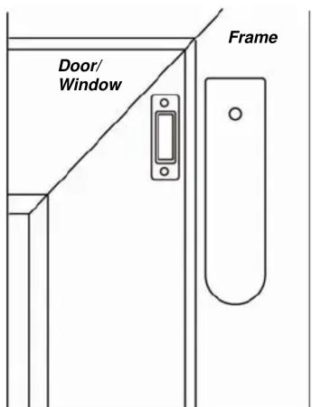
When mounting the Door Contact, please take note of the following points:
- Mount as high as possible
- Do not aim a PIR sensor at this window
- Do not mount on metallic surface
Operation
Test Mode
Press the Test Button to enter Test mode for 3 minutes. Under Test mode, the LED indicator will light up every time the Door Contact is triggered.
LED Indicator
| Off | Normal | Operation |
| On (2 seconds) - When Tamper Switch is triggered- Movement detection under low battery, tamper triggered, or Test mode. | ||
Battery
The Door Contact uses 2 x 1.5V AAA alkaline batteries as its power source. It also features low battery detection function to notify the Control Panel when battery voltage is low.
When the Door Contact is on low battery, follow the procedure below to change the batteries.
- Open the Door contact cover.
- Remove the old batteries.
- Press the learn button several times to fully discharge.
- Insert the new batteries observing correct polarity.
- Replace the cover.
Specification
Environmental Condition
-10°C to 40°C, relative humidity 85% non-condensing.
Radio
433 MHz
FCC Statement
This device complies with Part 15 of the FCC Rules. Operation is subject to the following two conditions:
(1) This device may not cause harmful interference, and
(2) This device must accept any interference received, including interference that may cause undesired operation.
FCC Caution:
To assure continued compliance, any changes or modifications not expressly approved by the party responsible for compliance may void the user's authority to operate this equipment. (Example - use only shielded interface cables when connecting to computer or peripheral devices).
Marke : BLAUPUNKT
Modell : DC-S2
Kategorie : Système de contrôle d'accès sécurisé