VB1080 - Nicht kategorisiert Rigol - Kostenlose Bedienungsanleitung
Finden Sie kostenlos die Bedienungsanleitung des Geräts VB1080 Rigol als PDF.


| Produkttyp | VSWR-Brücke |
| Modell | VB1080 |
| Marke | Rigol |
| Frequenzbereich | 2 GHz bis 8 GHz |
| Impedanz | 50 Ω |
| Anschlusstyp | N (Buchse) |
| Einfügungsdämpfung (IN zu DUT) | < 1 dB (typ.) |
| Direktivität | ≥ 20 dB (typ.), mind. 15 dB |
| Maximale Eingangsleistung | +27 dBm (0,5 W) |
| Abmessungen (ohne Verpackung) | 115 mm × 41 mm × 17,5 mm |
| Abmessungen (mit Verpackung) | 256 mm × 190 mm × 43 mm |
| Gewicht (ohne Verpackung) | 0,2 kg |
| Gewicht (mit Verpackung) | 0,9 kg |
| Betriebstemperatur | -20 °C bis 50 °C |
| Lagertemperatur | -40 °C bis 100 °C |
| Anwendungen | Messung von S11-Parametern (Rückflussdämpfung, Reflexionsfaktor, VSWR) an Filtern, Verstärkern, Mischern, Antennen |
| Kompatibilität | RIGOL DSA-Spektrumanalysatoren mit Tracking-Generator |
| Lieferumfang | VSWR-Brücke, zwei Dual-N-Stecker (männlich) |
| Reinigung | Mit einem trockenen, fusselfreien Tuch abwischen; keine aggressiven Reinigungsmittel verwenden |
Häufig gestellte Fragen - VB1080 Rigol
Benutzerfragen zu VB1080 Rigol
0 Frage zu diesem Gerät. Beantworten Sie die, die Sie kennen, oder stellen Sie Ihre eigene.
Eine neue Frage zu diesem Gerät stellen
Laden Sie die Anleitung für Ihr Nicht kategorisiert kostenlos im PDF-Format! Finden Sie Ihr Handbuch VB1080 - Rigol und nehmen Sie Ihr elektronisches Gerät wieder in die Hand. Auf dieser Seite sind alle Dokumente veröffentlicht, die für die Verwendung Ihres Geräts notwendig sind. VB1080 von der Marke Rigol.
BEDIENUNGSANLEITUNG VB1080 Rigol

VB1080 VSWR Bridge
Product Overview
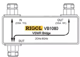
VB1080 is used in combination with the RIGOL DSA series spectrum analyzer to measure S11-related parameters (such as return loss, reflection coefficient and VSWR). VB1080 provides three N (Female) connectors as shown in the figure below.
— IN: Signal input terminal. Here the signal generator or the output terminal of the
tracking generator of the spectrum analyzer is connected.
— OUT: Signal output terminal. Here the power meter or the RF input terminal of the spectrum analyzer is connected.
— DUT: Here the device under test is connected.
Measurement Connection
Connect VB1080 to the spectrum analyzer as shown in the figure on the right.
— Connect the spectrum analyzer Use 2 Dual N (Male) adaptors to connect the output terminal of the tracking generator and the RF input terminal of the spectrum analyzer to the IN terminal and OUT terminal of the VSWR bridge respectively.
— Connect the device under test
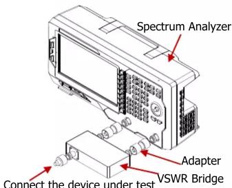
Do not use cables or adaptors as far as possible to avoid additional reflection.
Typical Applications
— Measurement of the S11-related parameters of the filter, amplifier, mixer, etc.
— Resonant frequency and VSWR tests of the antenna.
Specifications
| Frequency | |
| Frequency range 2 GHz to 8 GHz |
| Connector | ||
| Connector type N (Female) type | ||
| Adaptor dual N (Male) type | ||
| Impedance | 50 | |
| Insertion Loss |
| IN to DUT <1 dB (typical) |
| Directivity | |
| Typ. ≥20 dB | |
| Min. | 15 dB |
| Input Power | |
| Maximum input power + | 27 dBm (0.5 W) |
| General Specifications | |
| Dimensions | 115 mm×41 mm×17.5 mm |
| 256 mm×190 mm×43 mm (with package) | |
| Weight | 0.2kg |
| 0.9kg (with package) | |
| Operation temperature | -20 °C to 50 °C |
| Storage temperature | -40 °C to 100 °C |
Marke : Rigol
Modell : VB1080
Kategorie : Nicht kategorisiert