
RAS-S25YHAB - Klimaanlage HITACHI - Kostenlose Bedienungsanleitung
Finden Sie kostenlos die Bedienungsanleitung des Geräts RAS-S25YHAB HITACHI als PDF.

| Produkttyp | Split-Klimaanlage |
| Modell (Innengerät) | RAS-S25YHAB |
| Modell (Außengerät) | RAC-S25YHAB |
| Kältemittel | R32 |
| Kühl- und Heizbetrieb | Ja |
| Installationsrichtungen | 6 (hinten, links, rechts, unten) |
| Luftfilter | Washati Nano Titanium Air Cleaning Mesh (2 Stück) |
| Fernbedienung | Im Lieferumfang enthalten |
| Max. Höhenunterschied zwischen Innen- und Außengerät | 10 m |
| Sicherheitshinweise | Erdung erforderlich; Sicherungsautomat im Hausverteilerkasten |
| Werkzeuge für Installation | Schraubendreher, Maßband, Messer, Säge, Bohrer (ø65mm), Inbusschlüssel (4mm), Schraubenschlüssel (14/17/19/22mm), Lecksucher, Rohrschneider, Kitt, Vinylband, Zange, Bördelwerkzeug, Vakuumpumpenadapter, Manifoldventil, Ladeschlauch, Vakuumpumpe |
| Reinigung | Filter regelmäßig reinigen; Frontabdeckung abnehmbar |
| Notbetrieb (Force-Cooling) | Ja, über temporären Schalter (5 Sekunden drücken) |
| Abfluss (Kondenswasser) | Seitlich wählbar; mit Ablaufschlauch |
| Stromkabeltyp | NYM, IEC zugelassen |
| Sicherung | 15 A Zeitverzögerungssicherung |
Häufig gestellte Fragen - RAS-S25YHAB HITACHI
Benutzerfragen zu RAS-S25YHAB HITACHI
0 Frage zu diesem Gerät. Beantworten Sie die, die Sie kennen, oder stellen Sie Ihre eigene.
Eine neue Frage zu diesem Gerät stellen
Laden Sie die Anleitung für Ihr Klimaanlage kostenlos im PDF-Format! Finden Sie Ihr Handbuch RAS-S25YHAB - HITACHI und nehmen Sie Ihr elektronisches Gerät wieder in die Hand. Auf dieser Seite sind alle Dokumente veröffentlicht, die für die Verwendung Ihres Geräts notwendig sind. RAS-S25YHAB von der Marke HITACHI.
BEDIENUNGSANLEITUNG RAS-S25YHAB HITACHI
FOR SERVICE PERSONNEL ONLY
HITACHI
HITACHI SPLIT-UNIT AIR CONDITIONER INSTALLATION MANUAL

Indoor Unit / Outdoor Unit RAS-S25YHAB / RAC-S25YHAB RAS-S35YHAB / RAC-S35YHAB
- Carefully read through the procedures of proper installation before starting installation work. - The sales agent should inform customers regarding the correct operation of installation.
Tools Needed For Installation Work
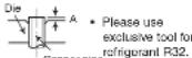
(Mark® is exc usive use tool for R32) ○○ Screwdriver · Measuring Tape · Knife · Saw · ø65mm PowerDrill · Hexagonal Wrench Key (4mm) · Wrench(14,17,19,22mm) · Gas leakage Detector · PipeCutter · Putty · Vinyl Tape · Pliers · Flare Tool · Vacuum Pump Adapter · Manifold Valve · Charge Hose · Vacuum Pump
SAFETY PRECAUTION

Read the safety precautions carefully before operating the unit. This appliance is filled with R32.
- The contents of this section are vital to ensure safety. Please pay special attention to the following sign
WARNING ...... Incorrect methods of installation may cause death or serious injury.
CAUTION ....Improper installation may result in serious consequence.
Make sure to connect earth line.
This sign in the figures indicates prohibition.
Be sure that the unit operates in proper condition after installation. Explain to customer the proper operation and maintenance of the unit as described in the user's guide. Ask a customer to keep this installation manual together with the instruction manual.
WARNING
- Please request your sales agent or qualified technician to install your unit. Water leakage, short circuit or fire may occur if you do the installation work yourself.
- Please observe the installation stated in the installation manual during the process of installation. Improper installation may cause water leakage, electric shock and fire.
- Make sure that the units are mounted at locations which are able to provide full support to the weight of the units. If not, the units may collapse and impose danger.
- Observe the rules and regulations of the electrical installation and the methods described in the installation manual when dealing with the electrical work. Use cables which are approved official in your country. Be sure to use the specified circuit. A short circuit and fire may occur due to the use of low quality wire or improper work.
- Be sure to use the specified cables for connecting the indoor and outdoor units. Please ensure that the connections are tight after the conductors of the wire are inserted into the terminals to prevent the external force is being applied to the connection section of the terminal base. Improper Insertion and loose contact may cause over-heating and fire.
- Please use the specified components for installation work. Otherwise, the unit may collapse or water leakage, electric shock, fire or stronger vibration may occur
- Be sure to use the specified piping set for R32. Otherwise, this may result in broken copper pipes or faults.
- When installing or transferring an air conditioner to another location, make sure that air other than the specified refrigerant (R32) does not enter the refrigeration cycle. If other air should enter, the pressure level of the refrigeration cycle may increase abnormally which could result in a rupture and injury.
- Never install a drier to this H32 unit in order to guarantee its lifetime.
- Bo sure to ventilate fully if a refrigerant gas leak while at work. If the refrigerant gas comes into contact with fire, a poisonous gas may occur.
- After completion of installation work, check to make sure that there is no refrigeration gas leakage. If the refrigerant gas leaks into the room, coming into contact with fire in the tan-driven heater, space heater, etc., a poisonous gas may occur.
- Unauthorized modifications to the air conditioner may be dangerous. If a breakdown occurs please call a qualified air conditioner technician or electrician. Improper repairs may result in water leakage, electric shock and fire, etc.
- Be sure to connect the earth line from the power supply wire to the outdoor unit and between the outdoor and indoor unit. Do not connect the earth line to the gas tube, water pipe, lighting rod or the earth line of the telephone unit. Improper earthing may cause electric shocks.
- When finishing the refrigerant collection (pumping down), stop the compressor and then remove the coolant pipe. If you remove the refrigerant pipe while the compressor is operating and the service valve is released, air is sucked and a pressure in the freezing cycle system will build up steeply, causing an explosion or injury.
- When installing the unit, be sure to install the refrigerant pipe before starting the compressor. If the refrigerant pipe is not installed and the compressor is operated with the service valve released, air is sucked and the pressure level of the refrigeration cycle may increase abnormally which could result in a rupture and injury.
CAUTION
- A circuit breaker must be installed in the house distribution box for the direct connected power supply cables to the outdoor unit. In case of other installations a main switch with a contact gap or more than 3mm has to be installed. Without a circuit breaker, the danger of electric shock exists.
- Do not install the unit near a location where there is flammable gas. The outdoor unit may catch fire
If flammable gas leaks around it.
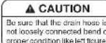
• Please ensure smooth flow of water when installing the drain hose. Improper installing may wet your funiture.
• An IEC approved power cord should be used. Power cord type: NYM.


THE CHOICE OF MOUNTING SITE

WARNING
- The unit should be mounted at stable, non-vibratory location which can provide full support to the unit.
CAUTION
- No nearby heat source and no obstruction near the air outlet is allowed.
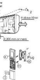
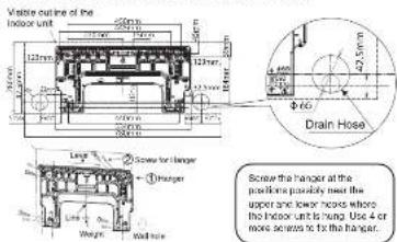
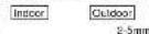
- The clearance distances from top, right and left are specified in figure below.
- The location must be convenient for water drainage and pipe connection with the Outdoor unit.
- To avoid interference from noise, please place the unit and its remote controller at least 1 m from the radio and television.
- To avoid any error in signal transmission from the remote controller, please put the controller far away from high-frequency machines and high-power wireless systems.
- The installation height should be at least 2,300 mm or more from the floor.

matters and obtain permission from customer before installation.)
▲ WARNING
The Outdoor unit must be mounted at a location which can support heavy weight. Otherwise, noise and vibration will increase.
A CAUTION
Selecting the installation location: Suitable location that will reduce the impact from rain and direct sun that may affect the unit performance.
- Besides, ventilation must be good and clear of obstruction.
- The air blown out of the unit should not point directly to animals or plants.
- The clearances of the unit from top, left, right and front are specified in figure below. At least three of the above sides must be open air.
- Be sure that the hot air blown out of the unit and noise do
• Do not install at a location where there is flammable gas, steam, oil and smoke.
- The location must be convenient for water drainage.
- Place the Outdoor unit and its connecting cord at least 1 r away from the antenna or signal line of television, radio or telephone. This is to avoid noise interference.
Names of Indoor Components
No. Item Qty 1 Hanger 1 2 Screw for Hanger 5 3 AAA size Battery 2 4 Remote Controller 1 5 Insulation sheet 1 6 Drain Pipe 1 7 Bush 2 8 Washati Nano Titanium Air Cleaning Mesh 2 9 C-case 2 10 Remote Controller Holder 1 11 Screw for Remote Controller Holder 2 12 Binding band 2
The component of ⑥ ⑦ is included in the package of the outdoor unit.
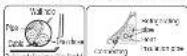
Direction of Piping
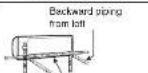
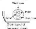
There are 6 directions allowed, namely, backward piping, backward piping from left horizontally piping from right horizontally piping from left vertically down from right, vertically down from left.
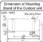
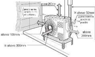
Figure showing the installation of Indoor and Outdoor Unit.
The indoor piping should be insulated with the enclosed insulator pipe. If the insulator is insufficient please use commercial products.)
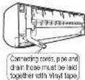
- The ret-gesting machine oil is easily affected by moisture. Use caution to prevent water from entering the cycle. - The difference in height between the indoor and outdoor unit should be kept above 10m. - The connecting pipe, no matter big or small, should all be insulated with insulation pipe and then wrapped with vinyl tape. (The insulator will deteriorate if it is not exposed with tape)
The connection of insulated drain hown Inner diameter: 16mm Please use insulated drain nose for the indoor piping (commercial packet)
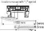
1 Installation of Hanger, Wall Penetration and Installation of Protection Pipe
CAUTION
- The draining of the water container inside the indoor unit can be done from the left. Therefore the hanger must be fixed horizontally or slightly tilted towards the side of drain hose. Otherwise, condensed water may overflow the water container.
Direct Mounting On The Wall
- Please use hidden beams in the wall to hold the hanger.
2 Installation Of The Indoor Unit
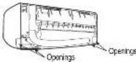
Cutting Low Cover bush
While installing the pipe from the right, left or bottom side, use a knife to cut openings as shown in figure. Then smoothen the edges of openings with a file.
1) PIPING FROM THE RIGHT SIDE (BACKWARD, DOWNWARD, HORIZONTAL)
Preparation
- Connect connecting cord
• Pull out the pipe, connecting cord and drain hose.
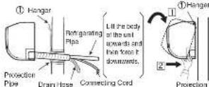
Installation
- Insert the pipe through the wall hole.
① The upper part of the indoor unit is hanged on the
hangar.
2 The projection at the lower part of the indoor unit is hooked onto the hanger.
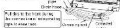
[2] PIPING FROM THE LEFT SIDE (BACKWARD, DOWNWARD, HORIZONTAL)
Preparation
Changed of Drain Hose and Installation Procedures.
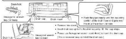
- Exchange the location of drain hose and drain cap while installing the pipe from the left side as shown in below. Be sure to plug in the drain hose until the insulating material folds upon itself.
- Please use plers to pull out the drain cap. (This is an easier way to remove the drain cap).
![HITACHI RAS-S25YHAB - [2] PIPING FROM THE LEFT SIDE (BACKWARD, DOWNWARD, HORIZONTAL) - 1](/content/2026/05/891869/images/864121c9609550ebeccced630dfbc5471bbeb1bd085d571e35bf3f4e54bfb735.jpg)
INSTALLATION AFTER CONNECTION OF REFRIGERATING PIPES
- The refrigerating pipe should be adjusted to fit into the hole on the wall and then ready for further connection.
- The terminals of 2 connected pipes must be covered with insulator used for terminal connection. Then the pipes are wrapped with insulation pipe.
- Connect the connecting cord after removing low cover.
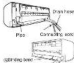
(Refer to 'CONNECTION OF POWER CORD') • After adjustment, fit the connecting cord and pipes into the space available under the unit. Use holder I hold them light. - Holder can be attached at the either of 2 places. Please select the easier position.
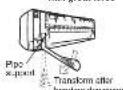
THE CONNECTION OF REFRIGERATING PIPE DURING THE INSTALLATION OF INDOOR UNIT
(Preparation To Install Refrigerating Pices)
- The refrigerating pipes and connecting cord transform and are attached.
Ewing, doing can be reduced in whether side of the installation points. However, it is recommended in each it on the right side overing from the man.
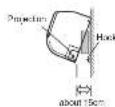
Installation
Hang the indoor unit onto the hanger. Use the temporary stand at the back of the indoor unit to push its lower part 15cm forwards.
- Place the drain hose through the hole on the wall
- Wrap the refrigerating pipes with insulation pipe after
connecting refrigerating pipe.
- Connect the connecting cord after removing low cow
(Haier to Connection of Power cord)
- After Bojazimani, the corrigating use and reorganizing places are placed into the space available under the Indocs unit.
• The projection of indoor unit must hook to the hinge
The are of the relsporal rings pipes are at
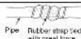
3 Heat Insulation and Finish of the Piping
- The connected terminals should be completed sealed - Insulation material for pipe
With rest insulator and then tied up with rubber strap. Do not tie the terminology with the top ice tight.
If any clearance or over-tightening may cause condensation. - Please tie the pipe and power line together with vinyl tape as shown in the figure showing the installation of Indope and Outdoor units.
• To enhance the heat insulation and to prevent water condensation, please cover the outdoor part of the
drain hose and pipe with insulation
4 Installation of Drain Hose

You are free to choose the side (left or right) for the installation of drain hose. Please ensure the smooth flow of condensed water of the indoor unit during installation. (Careless may result in water leakage.)
Procedures of Installation and Precautions
- Procedures to fix the hanger
- Drill holes on wall. (As shown below)


• Procedures to fix the holder of remote control.
- Drill holes on wall. (As shown below)

- Push plug into the holes. (As shown below)
WARNING
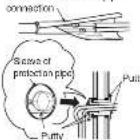
Wall Penetration and Installation of Protection Pipe
Drill a 065mm hole on wall which is slightly tilted towards the outdoor side. Drill the wall at a small angle.
- Cut the protection pipe according to the wall thickness.
- Empty gap in the sleeve of protection pipe should be completely sealed with putty to avoid dripping of rain water into the room.
- Please ensure smooth flow of water when installing the drain hose. Improper installing may wel your furniture.
- An IEC approved power cord should be used. Power cord type: NYM.
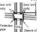
protection pipe
be sure that the wire is not in contact with any metal in the wall. Please use the protection pipe as wire passing through the hollow part of the wall so as to prevent the possibility of damaged by mouse. Unless it seals completely, any air with high humidity levels from outdoor and any dew may drop.
CAUTION
Be sure that the wire is not in contact with any metal in the wall. Please use the protection pipe as wire passing through the hollow part of the wall so as to prevent the possibility of damaged by mouse. Unless it seals completely, any air with high humidity flows from outdoor and any dew may drop.
- The rubber strap used for fixing the insulator should not be tied with great force. Otherwise, this will damage heat insulation and causes water condensation.
- Please pull the lower part of the indoor unit outwards to check if the unit is hooked onto the hanger. Improper installation may cause vibration and noise.
- Transform the piping while holding down the lower portion of pipe-support by hand.
OUTDOOR UNIT
- Please mount the Outdoor unit of stable ground to prevent vibration and increase of noise level.
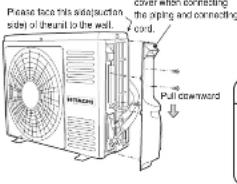
- Decide the location for piping after sorting out the different types of pipe available
- When removing side cover, please pull the handle after undoing the hook by pulling it downward. Reinstall the side cover in the reverse order of the removal.
Please remove side
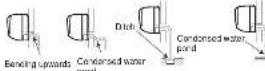
CONDENSED WATER DISPOSAL OF OUTDOOR UNIT
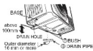
- There is holes on the base of Outdoor unit for condensed water to exhaust. - In order to flow condensed water to the drain, the unit is installed on a stand or a block so that the unit is 100mm above the ground as shown figure. Join the drain pipe to one hole.
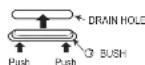
- Cover the drain hole with a bush. To install the bush, put it on the drain hole as shown in the figure and press the both sides of the bush to fit into the hole. After installation, check whether the drain pipe and bush cling to the base firmly
- Install the outdoor unit horizontally and make sure that condensate drains away. - In case of using in chilly area
Especially, in case that there are many snows by very cold in chilly area, condensed water freezes on the base and may result not to drain. In this case, please remove the bush and the drain pipe at the bottom of unit. (Left and center near discharge portion of air, each 1 place). It becomes smooth drain.
Ensure that the distance from the drain hole to the ground is 250 mm or more.
INSTALLATION OF REFRIGERATING PIPES AND AIR REMOVAL
1 Preparation of Pipe
- Use a pipe cutter to cut the copper pipe and remove bum.

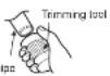
CAUTION
- Remove burr and jagged edge will cause leakage. - Point the side to be trimmed downwards during trimming to prevent copper chips from entering the pipe.
• Before flaring, please put on the flare nut.

| Outer Diameter (Ω) | A (mm) Rigid Flaring Tool | |
| For R32 tool | For R22 tool | |
| 8.35 (1/4") | 0 - 0.5 | 1.0 |
| 9.52 (3/6") | 0 - 0.5 | 1.0 |
2 Pipe Connection
CAUTION
In case of removing flare nut of a indoor unit, first remove a nut of small diameter side, or a seal cap of big diameter side will fly out. Free from water into the piping when working.
Be sure to tighten the flare nut to the specified torque with a torque wrench.
If the flare nut is overtightened, the nut may be split after a long period has passed, and may cause a refrigerant leak.
- Please be careful when bending the copper pipe.
- Screw in manually while adjusting the center. After that, use a torque wrench to lighten the connection.
| Wrench Torque wrench | Flare nut Small diameter side | Couter diameter of pipe (g) | Torque N·m (kg/cm) |
| 8.35 (14") | 13.7-18.6 (140-190) | ||
| Large diameter side | 9.52 (38") | 34.3-41.1 (950-150) | |
| Vane Small diameter side | 6.35 (14") | 19.5-24.5 (200-250) | |
| Total cap Large diameter side | 9.52 (38") | 19.5-24.5 (200-250) | |
| Vane pore cap | 12.3-15.7 (125-160) |
Remove of Air From The Pipe And Gas Leakage Inspection
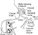
Procedures of using Vacuum Pump for Air Removal
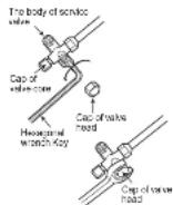
As shown in right figure, remove the cap of valve core. Then, connect the charge hose. Remove the cap of valve head. Connect the vacuum pump adapter to the vacuum pump and connect the charge hose to the adapter.
(-76cmHg) during pumping fully tighter the shuttle.
2
Fully tighter the "Hi" shuttle of the manifold valve and completely unscrew the "Lo" shuttle. Run the vacuum pump for about 10-15 minutes, then completely tighten the "Lo" shuttle and switch off the vacuum pump.
- Loose the spindle of the service valve with small diameter by 1/4 turn and tighten the spindle immediately after 5 to 6 seconds.
- Remove the charging hose from the service valve.
3
Completely unscrew the spindle of the service valve (at 2 places) in anticlockwise direction to allow the flow of refrigerant (using Hexagonal Wrench key).
4
Tighten the cap of valve head. Check the cap's periphery if there is any gas leakage. The task is then completed.
When pumping alerts, slightly loosen the flare nut to check of air suction in. Then tighten the flare nut.
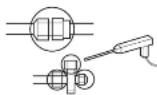
Gas leakage inspection
Please use gas leakage detector to check if leakage occurs at connection of Flare nut as shown on the right.
If gas leakage occurs, further tighten the connection to stop leakage.
WARNING • THIS APPLIANCE MUST BE EARTHED.
Procedures of Wiring
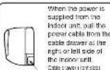
When power supplies to Indoor Unit
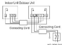
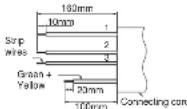
Detail of cutting the connecting cord

Outdoor Unit
▲ WARNING
- The naked part of the wire core should be 10mm fix it to the terminal tightly. Then try to pull the individual wire to check if the contact is tight. Improper insertion may burn the terminal.
- Be sure to use only wire specified for the use of air-conditioner.
- Please refer to the manual for wire connection and the wiring technique should meet the standard of the electrical installation.
- There is an AC voltage drop between the LN terminal if the power is on. Therefore, be sure to remove the plug from its socket.
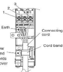
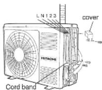
▲ WARNING
- Leave some space in the connecting cord for maintenance
purpose and be sure to secure it with the cord band. - Secure the connecting cord along the coated part of the using the cord band. Do not exert pressure on the wire as this may cause overheating or fire.
WARNING
Outdoor supply cords shall not be lighter than polychloroprene shealhed flexible cord 60245 IEC 57.
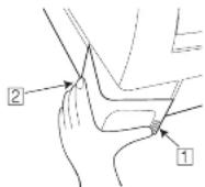
Method to remove the low cover
- Pull at the 1 and 2 in the directions as shown by arrows to remove the cover.
Wiring of the Outdoor Unit
- Please remove the side cover for wire connection.
WARNING
- If you cannot attach the side plate due to the connection cord, please press the connecting cord in the direction to the front panel to fix it. - Be sure that the hooks of the side cover fixed in certainly. Otherwise water leakage may occur and this causes short circuit or faults. - The connecting cord should not touch to service valve and pipes. (It becomes high temperature in heating operation.)
Checking for the electric source and the voltage range
- Before installation, the power source must be checked and necessary wiring work must be completed. To make the wiring capacity proper, use the wire gauge list below for the wiring from house distribution fuse box to the outdoor unit in consideration of the blocked color current.
IMPORTANT
| Wire length | Wire gauge |
| up to 6m | 1.5mm ^2 |
| up to 15m | 2.5mm ^2 |
| up to 20m | 4.0mm ^2 |
- Investigate the power supply capacity and other electrical conditions at the installing location. Depending on the model of room air conditioner to be installed, request the customer to make arrangements for the necessary electrical work etc. The electrical work includes the wiring work up the outdoor unit. In localities where electrical conditions are poor, use of a voltage regulation is recommended. - Install outdoor for the room air conditioner within the reaching range of the line cord.
IMPORTANT
| Fuse Capacity |
| 15A time delay fuse |
1 Power Source And Operation Test
Power Source
▲ WARNING
- Never remodel the power plug nor extend the long-distance
cord. - Keep additional length for the power cord and do not render
the plug under external force as this may cause Do not fix the power cord with U-shape nail - The power cable easily generates heat. Do not bring the cable together with a wire or vinyl tie.
Operation test
- Please ensure that the air conditioner is in normal operating condition during the operation test.
- Explain to your customer about the proper operation procedures as described in the operation manual.
- If the indoor unit won't operate, check the cable for correct connection.
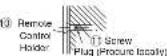
2 Installation of Remote Controller
The remote controller can be placed in its holder which is fixed on wall or beam.
To operate the remote controller at its holder, please ensure that the unit can receive signal transmitted from the controller at the place where the holder is to be fixed. The unit will beep when signal is received from the remote controller. The signal transmission is weaken by the fluorescent light. Therefore, during the installation of the remote control holder, please switch on the light, even during day time, to determine the mounting location of the holder.
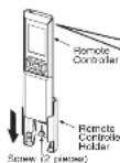
The remote controller must be slide in the remote controller holder, in the direction as shown in the figure, until it hooks at the lower end of the remote controller holder.
Force-cooling operation
- When the temporary switch of the indoor unit is pressed for more than 5 seconds, or the service switch of the outdoor unit is pressed for 1 or more seconds. the force-cooling operation starts.
Use this mode when performing the failure diagnosis or collecting refrigerant into the outdoor unit. - The Timer lamp flashes when force-cooling is in operation.
- Press the temporary switch again or use the remote controller to stop the force-cooling operation once this operation is completed.
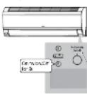
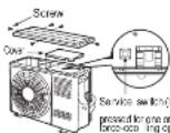
CAUTION - Do not operate the unit for more than 5 minutes while the spindle of the service valve is closed.
Temporary switch (Force-cooling operation starts when the switch is pressed for more than 5 seconds. Press the switch again and use the remote controller to stop the operation.)
How to remove the front cover
1 Remove the front panel
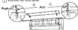
① Push the end of the right-side arm outward to release the tab.
② Move the left-side arm outward to release the left tab, and then pull the panel towards you.
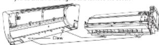
2 Remove the filters
3 After removing 3 screws, remove the cover of electric box pull the center of the front cover towards you and release the claws.
4 Pull the side laces (lower sections) of the front cover towards you as shown in the figure and remove the cover.
How to Attach the Front Cover
1 After installing the front cover onto the unit, hook three claws at upper side of the cover securely. Then, push the center of the front cover to lock the claws.
② Assemble the cover of electric box.
3 Tighten the 3 screws.
4 Install the filter.
5 Attaching the Front Panel
- Insert the shaft of the left arm along the step on the unit into the shaft.
the hole
- Electrically I-beach the small drive light arm riding the soap on the unit into the hole.
- Make sure that the front panel is securely attached, and then close the front panel.
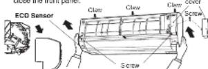
CAUTION
- Remove and attach the front cover to the direction as shown in the figure to ensure no damage occurs to the ECO sensor.

Gas leakage inspection
HOW TO REMOVE INDOOR UNIT
- Push up the [PUSH] sections at the bottom of the indoor unit and pull the bottom plate towards you. Then the claws are released from the stationary plate. (The [PUSH] sections are indicated by 2 arrows in the right figure)
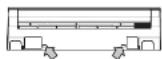
[PUSH] mark positions
- FOR SERVICE PERSONNEL ONLY
- HITACHI
- HITACHI SPLIT-UNIT AIR CONDITIONER INSTALLATION MANUAL
- Tools Needed For Installation Work
- SAFETY PRECAUTION
- WARNING
- CAUTION
- THE CHOICE OF MOUNTING SITE
- ▲ WARNING
- A CAUTION
- Installation of Hanger, Wall Penetration and Installation of Protection Pipe
- Direct Mounting On The Wall
- Installation Of The Indoor Unit
- 1) PIPING FROM THE RIGHT SIDE (BACKWARD, DOWNWARD, HORIZONTAL)
- [2] PIPING FROM THE LEFT SIDE (BACKWARD, DOWNWARD, HORIZONTAL)
- INSTALLATION AFTER CONNECTION OF REFRIGERATING PIPES
- THE CONNECTION OF REFRIGERATING PIPE DURING THE INSTALLATION OF INDOOR UNIT
- Installation
- Heat Insulation and Finish of the Piping
- Installation of Drain Hose
- Procedures of Installation and Precautions
- Wall Penetration and Installation of Protection Pipe
- OUTDOOR UNIT
- INSTALLATION OF REFRIGERATING PIPES AND AIR REMOVAL
- Preparation of Pipe
- Pipe Connection
- Remove of Air From The Pipe And Gas Leakage Inspection
- 2
- 3
- 4
- Gas leakage inspection
- WARNING • THIS APPLIANCE MUST BE EARTHED.
- Procedures of Wiring
- Method to remove the low cover
- Wiring of the Outdoor Unit
- Checking for the electric source and the voltage range
- Power Source And Operation Test
- Power Source
- Operation test
- Installation of Remote Controller
- Force-cooling operation
- How to remove the front cover
- How to Attach the Front Cover
- HOW TO REMOVE INDOOR UNIT
Marke : HITACHI
Modell : RAS-S25YHAB
Kategorie : Klimaanlage