BKSP - Lautsprecher Vantage Point - Kostenlose Bedienungsanleitung
Finden Sie kostenlos die Bedienungsanleitung des Geräts BKSP Vantage Point als PDF.


| Produkttyp | Lautsprecherhalterung für Regallautsprecher |
| Marke | Vantage Point |
| Modell | BKSP |
| Maximale Lautsprechergewicht | 11,3 kg (25 lbs) |
| Montagemöglichkeiten | Holzständer, Vollbeton, Hohlblock |
| Verstellbarkeit | Neigung und Schwenkung über Gelenke einstellbar |
| Material | Stahl (vermutlich) |
| Farbe | Schwarz (Standard) |
| Lieferumfang | 1 Wandplatte, 1 Lautsprecherplatte, 2 Verbindungsstücke, 4 Abdeckkappen, Schraubenset, Inbusschlüssel |
| Enthaltene Schrauben | #14 x 2" und #14 x 1" Selbstschneidend, 1/4"-20 x 3/4" Maschinenschrauben, 5/16"-18 x 3/4" Kugelkopfschrauben |
| Dübeltyp | Toggler Alligator Anchor (4 Stück) |
| Werkzeug enthalten | Inbusschlüssel 3/16" |
| Bohrer erforderlich | Ja (1/8" für Holz, 5/16" Steinbohrer für Beton) |
| Garantie | Lebenslange Garantie auf Material- und Verarbeitungsfehler |
| Hersteller | Vantage Point Products Corp. |
| Herstellerkontakt | Tel: 1-800-582-9595 (USA), E-Mail: cons-serv@vanptc.com |
| Montageanleitung | Mehrsprachig (DE, EN, etc.) als PDF verfügbar |
| Anwendungsbereich | Regallautsprecher bis 25 lbs, Innenmontage an Wand oder Decke |
| Sicherheitshinweis | Nur für angegebene Gewichtsgrenze; vor Bohren Leitungen und Wasserrohre prüfen |
| Zusatzoption | Einzelpfosten-Adapter separat erhältlich (Art.-Nr. auf Anfrage) |
Häufig gestellte Fragen - BKSP Vantage Point
Benutzerfragen zu BKSP Vantage Point
0 Frage zu diesem Gerät. Beantworten Sie die, die Sie kennen, oder stellen Sie Ihre eigene.
Eine neue Frage zu diesem Gerät stellen
Laden Sie die Anleitung für Ihr Lautsprecher kostenlos im PDF-Format! Finden Sie Ihr Handbuch BKSP - Vantage Point und nehmen Sie Ihr elektronisches Gerät wieder in die Hand. Auf dieser Seite sind alle Dokumente veröffentlicht, die für die Verwendung Ihres Geräts notwendig sind. BKSP von der Marke Vantage Point.
BEDIENUNGSANLEITUNG BKSP Vantage Point
Step 3a. Optional Speaker Post Style Mounting
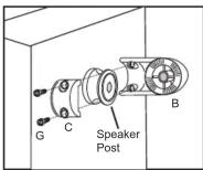
OPTION. SINGLE POST INSTALLATION A single post adapter is available for purchase. To purchase call 1-800-582-9595.
Model BKSP Bookshelf Speaker Mount Assembly Instructions
VANTAGE POINT Possibilities are mounting.
IMPORTANT CONSIDERATIONS PRIOR TO INSTALLATION
Preview all steps before beginning. Should any portion of these instructions be unclear, contact us at 800-582-9595 for assistance. Do Not Attempt to install this speaker mount if you have any doubts as to its proper installation. This speaker mount is specifically designed for mounting speakers weighing 25 lbs. or less. Use of this speaker mount for any other purpose unless specified by the manufacturer is not recommended.

Maximum Speaker Weight: 25 lbs
Supplied is mounting hardware for 3 different surface applications. You will need to determine what s hardware will work best with your mounting surface. NOTE: Always use CAUTION when drilling into a wall or ceiling. Make sure you are avoiding all electrical and water lines. Not all installation applications support themaximum rated weight of this product. The installer is responsible for evaluating the integri of materials and structure prior to mounting speaker.
WARRANTY INFORMATION
All Vantage Point Products Corp. products are manufactured to ensure superior quality, performance and durability for a lifetime of use. Warranty covers the product to be free of defects in materials and workmanship under normal and reasonable use. Vantage Point Products will repair or replace, at our option, any product which proves to be defective upon our inspection. This warranty will not apply to products that have been lost or damaged by misuse, abuse or accident, altered or repaired in any way or by any person or firm other than specified by us, used in violation of instructions or incorrect assembly nor used in a manner other than specified by us. This warranty is nontransferable to a new owner and may require proof of purchase. All claims must be directly handled with Vantage Point Products Corp. by calling us at 1-800-582-9595.
Vantage Point Products Corp • P.O. Box 2485 Santa Fe Springs, CA 90670 USA USA Tel: 1.800.582.9595 • Canada Tel: 905.607.9994 • Europe Tel: 31.72.581.6056
Web Site: www.vanptc.com • Email: cons-serv@vanptc.com
rev-09/05
Step 1. Attaching Speaker Plate
Supplied are parts and hardware for mounting to various manufacturers speakers. You will need to select the type that best suits your application. If the hardware provided does not fit your speaker you will need to acquire the appropriate hardware. CAUTION: RECOMMENDED HARDWARE PROVIDED IS DESIGNED FOR SPEAKER WEIGHTS INDICATED. INSTALLER MUST CONSIDER THE INTEGRITY AND DESIGN OF THE SPEAKER CABINET. SOME INSTALLATIONS MAY REQUIRE THE INSTALLATION OF A THROUGH BOLT AND REINFORCEMENT BACKING IF SPEAKER CABINET DESIGN WILL NOT SUPPORT SPEAKER WEIGHT.

Step A. Remove all parts from packaging.
Disassemble the Link Assemblies (B) by removing Button Head Allen Screw (E) using the 3'16" Allen Tool (L) provided. The Semated Binder Nut (F) has been pressed in at the factory and should not be loosened or removed! Remove plastic covers (D). Loosen the Socket Head Cap screws (G) slightly allowing Links (B) to rotate freely.
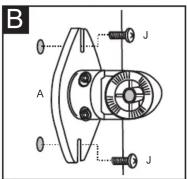
Step B. INSTALLING SPEAKER PLATE
(1/4-20 Threaded Holes in speakers)
Using the 1/4-20 x 3/4" machine screws (J) align the Speaker Plate (A) over the threaded holes, install the screws (J) and secure to speaker cabinet.

Step C. INSTALLING SPEAKER PLATE (No Threaded Holes, Wood Cabinet)
Locate the optimum mounting position for the Speaker Plate (A). Using Speaker Plate (A) as a template, mark for drilling speaker cabinet. NOTE: You do not want to drill or screw into the speaker where you could possibly damage internal components. Drill holes in Speaker cabinet using a 1/8" drill bit. These holes should be drilled no more than 3/4" deep. (You can accomplish this by placing a piece of tape 3/4" from the end of the drill bit providing you with a guide.) Using the #14 x 1" Self Tapping screws (I) mount the Speaker Plate (A) to the Speaker Cabinet.
Step 2. Installing Wall / Ceiling Plate
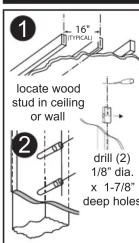

SOLID WOOD OR WOOD STUD
Using a stud finder locate the wood stud or framing member. Using a pick or small drill bit locate the center of the wood stud, be careful doing this as you don't want to go any wider than the width of the Speaker Wall Plate (A) (wall plate will cover any extra holes) Using the wall plate as a template mark hole position on mounting surface (see fig. 1). NOTE: wall mounting applications position mounting holes in a vertical pattern. Drill holes through the drywall and into the wood stud using a 1/8" drill bit. These holes should be drilled no less than 1-7/8" deep (see fig 2) You can accomplish this by placing a piece of tape a 1-7/8" from the end of the drill bit providing you with a guide. After holes are drilled, mount the wall plate using the #14 x 2" self tapping screws (H).

SOLID CONCRETE OR HOLLOW BLOCK
Using the Speaker wall plate (A) as a template mark hole position on mounting surface (see fig. 1). NOTE: In wall mounting applications, position mounting holes in a vertical pattern. (see fig.) Drill holes in the solid concrete or hollow block using a 5/16" masonry drill bit. Once holes are drilled insert the (4) #14 TOGGLE® ALLIGATOR ANCHORS® (K) into the holes making sure anchor is flush with wall or ceiling surface (see fig. 2). With TOGGLE® ALLIGATOR ANCHORS® (K) in place, mount the wall plate using the #14 x 2" self tapping screws (H). (see fig. 3)

Step 3. Speaker Mounting
Step A. POSITIONING and MOUNTING SPEAKER MOUNT Leaving Plastic Covers (D) off. Re-assemble the Links (B) using the previously removed 5'16"-18 x 34" button head link screw (E). Adjust Speaker assembly to desired positioning and tighten 5'16"-18 x 34" button head link screw (E) using the 3'16" allen wrench (L). Next tighten the socket head cap screws (G) to hold the speaker in its final position. Before cover installation evaluate speaker positioning. If not satisfied loosen and reposition at this time. Once covers are installed you cannot easily adjust the speaker position.

Step B. COVER INSTALLATION Remove the 5/16"-18x3/4" button head link screw (E). Install the Plastic Speaker Plate Cover (D), over the Speaker Plates (A). Re-install the 5/16-18 x 3/4" button head link screw (E) and secure.
Marke : Vantage Point
Modell : BKSP
Kategorie : Lautsprecher