
PlatinumX KB4807-3MP-PLTMX - Heizung KING - Kostenlose Bedienungsanleitung
Finden Sie kostenlos die Bedienungsanleitung des Geräts PlatinumX KB4807-3MP-PLTMX KING als PDF.


| Produkttyp | Elektronisches Heizgerät mit Fernbedienung und optionalem Raumthermostat |
| Modell | PlatinumX KB4807-3MP-PLTMX |
| Marke | KING |
| Spannung | 240 V (ein- oder dreiphasig, werkseitig auf einphasig eingestellt) |
| Leistung | ca. 4,8 kW (geschätzt) |
| Gewicht | ca. 11 kg (geschätzt) |
| Abmessungen (ca.) | 330 x 330 x 330 mm (geschätzt) |
| Montage | Wand- oder Deckenmontage mit beiliegender Universalhalterung |
| Mindestmontagehöhe | 1,83 m über dem Boden (2,44 m für Kanada) |
| Mindestabstand zu Wänden | 15 cm |
| Steuerung | Integrierte Steuerung per Display und Infrarot-Fernbedienung, optionaler 24-V-Raumthermostat (auch Nest-kompatibel) |
| Heizstufen | 1- oder 2-stufig (über DIP-Schalter wählbar) |
| Temperaturbereich | 4 °C bis 37 °C (40 °F bis 99 °F) |
| Timer | 1–9 Stunden |
| Lüftermodus | Nur Lüfter (ohne Heizung) |
| Displayfunktionen | Raumtemperaturanzeige, Display-Sperre, Schlafmodus (Display schaltet nach 30 s aus) |
| Differenz (Schaltdifferenz) | Einstellbar von 0 bis 5 |
| Sicherheit | Thermische Überlastsicherung (Smart Limit Protection) mit manuellem Reset |
| Schutzart | Nicht für explosionsgefährdete Bereiche geeignet |
| Zubehör (optional) | 24-V-Raumthermostat, Nest-Thermostat, Trennschalter |
| Reinigung | Heizelement und Lüfter saisonal mit Druckluft reinigen |
| Kundendienst | Kostenlose Hotline: 1-800-603-5464 (Mo–Fr, 7:00–15:30 Uhr PST) |
Häufig gestellte Fragen - PlatinumX KB4807-3MP-PLTMX KING
Benutzerfragen zu PlatinumX KB4807-3MP-PLTMX KING
0 Frage zu diesem Gerät. Beantworten Sie die, die Sie kennen, oder stellen Sie Ihre eigene.
Eine neue Frage zu diesem Gerät stellen
Laden Sie die Anleitung für Ihr Heizung kostenlos im PDF-Format! Finden Sie Ihr Handbuch PlatinumX KB4807-3MP-PLTMX - KING und nehmen Sie Ihr elektronisches Gerät wieder in die Hand. Auf dieser Seite sind alle Dokumente veröffentlicht, die für die Verwendung Ihres Geräts notwendig sind. PlatinumX KB4807-3MP-PLTMX von der Marke KING.
BEDIENUNGSANLEITUNG PlatinumX KB4807-3MP-PLTMX KING
INSTALLATION AND MAINTENANCE

king
KB PLATINUMX
Electronic Unit Heater with Remote Thermostat Option

DANGER

ELECTRIC SHOCK OR FIRE HAZARD
READ ALL WIRE SIZING, VOLTAGE REQUIREMENTS AND SAFETY DATA TO AVOID PROPERTY DAMAGE AND PERSONAL INJURY
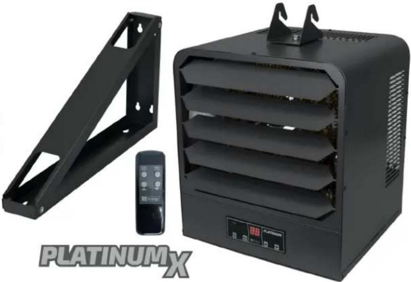
natural_image
Exterior view of a black PLATINUM X air conditioner unit with metal frame and control panel (no signage or text on main subject)
WARNING

READ CAREFULLY - Use the heater only as described in this manual. Any other use is not recommended and could result in fire, electric shock, and personal injury. Following these instructions will prevent difficulties that might occur during the installation and use of the heater. Please study the instructions first, as they may save considerable time and trouble during use addition to providing important safety information. Make sure to save these instructions for future use.
WARNING
To prevent a possible electrical shock, disconnect all power coming to heater at main service panel before wiring or servicing.
WARNING
All wiring must be in accordance with the National Electrical Code (Canadian Electrical Code in Canada) and all applicable local codes. The heater must be grounded as a precaution against electrical shock. Supply wiring must be copper and suitable for at least 75^ .
WARNING
Verify power supply and control voltages coming to the heater match the ratings printed on the heater nameplate before energizing.
WARNING
Heater must be installed so the minimum clearances shown in Specifications table are maintained.
WARNING
This heater is NOT suitable for use in hazardous locations as described by the National Fire Protection Association (NFPA). this heater has hot and arcing or sparking parts inside. DO NOT use in areas where gasoline, paint or other flammable liquids are used or stored.
WARNING
The mounting structure and anchoring hardware MUST BE capable of reliably supporting the weight of the heater plus mounting bracket if used. Refer to specifications table for heater weight.
WARNING
Heater air flow MUST be directed parallel to or away from adjacent walls.
WARNING
To prevent a possible fire, DO NOT block air intakes or exhaust openings in any manner. DO NOT allow foreign objects to enter grill openings as this may cause electric shock, fire or damage to heater.
WARNING
Louver adjustment (Do not attempt to adjust while heater is operational): The Louvers are opened during testing at factory, but may have shifted during shipping, make sure the louvers are rotated less than 45 degrees from horizontal before operation. To adjust the opening angle, grasp the left and right end of louver and twist with two hands to the desired position. CAUTION: Increasing the angle beyond 45^ degrees from horizontal may restrict air flow casing the over temperature limit to activate and shut off the heater.
CAUTION—RISK OF ELECTRIC SHOCK DO NOT OPEN HEATER SHELL

KING ELECTRIC MFG CO · 9131 10TH AVENUE SOUTH · SEATTLE, WA 98108 · PH:206 762 0400 · FAX: 206 763 7738 · www.king-electric.com
KB PLATINUMX INSTALLATION

CAUTION!
Turn OFF all electrical power to install heater
Figure 2-1

DANGER

ELECTRIC SHOCK OR FIRE HAZARD
READ ALL WIRE SIZING, VOLTAGE REQUIREMENTS AND SAFETY DATA TO AVOID PROPERTY DAMAGE AND PERSONAL INJURY
Selecting A Location For Your Heater:
The heater should be installed out of the reach of persons. The direction of air flow should not be restricted by machinery, beams, columns or partitions, etc., and the air flow should wipe exposed walls rather than blowing directly at them.
Heaters should be directed away from room occupants in comfort heating and are directed along the windward side when installed in a building exposed to a prevailing wind.
Small rooms can be heated by one unit heater. Large rooms require multi-unit installations. Number and capacity of units will be determined by volume of building and square feet of floor area to be heated.
When more than one heater is used in an area the heaters should be arranged so that the air discharge of each heater supports the air flow of the others to provide best circulation of warm air.
(see air flow chart)


Unpack & Inspect Your New Heater
Remove heater from the box and inspect it for any damage. Verify you have received the universal wall/ceiling mounting bracket.
Tools Needed
You will need the following tools to install your unit heater:
- Screwdriver - (Phillips head & slotted)
- Wire Cutters
• Pliers
- Adjustable Wrench
• Electric Drill
Hardware Needed For Installation
You will also need the following hardware, which can be purchased from your local hardware store or electrical supply house:
- adequate gauge and length of wire for your application
• proper size fuses or breakers to handle amperage
• proper wire connectors for your application - fasteners appropriate for application that are strong enough to hold unit
For certain applications conduit may be required. Check local electrical codes. Also, if you run the wiring in conduit and wish to be able to turn the heater, be sure to purchase enough flexible conduit to allow the heater to be turned.

Mounting Height
When the airflow of the heater is directed vertically or horizontally the minimum mounting height of 6 feet above floor (8 feet above floor for Canada).
Mounting heights depend upon building utilization and heater kW capacity.
Distance From Vertical Side Walls
Be sure to maintain 6" minimum clearance to walls and ceilings.
KING ELECTRIC MFG CO · 9131 10TH AVENUE SOUTH · SEATTLE, WA 98108 · PH:206 762 0400 · FAX: 206 763 7738 · www.king-electric.com
KB PLATINUMX INSTALLATION

DANGER

ELECTRIC SHOCK OR FIRE HAZARD
LINE VOLTAGE IS PRESENT ON SOME OF THE TERMINALS ON THE CONTROL TERMINAL BOARD. ALWAYS DISCONNECT THE POWER FROM THE HEATER BEFORE MAKING ANY CONNECTIONS TO THE CONTROL BOARD TO PREVENT ELECTRIC SHOCK HAZARD.

natural_image
Platinum X industrial heater with metal frame, control panel, and remote control unit (no visible text or symbols on main components)KB PLATINUMX WIRING
WIRING Branch Circuit (Power)
- Connect heater only to the voltage, and frequency specified on the nameplate.
- Field wiring must be properly sized to carry the amperage of the heater in accordance with the NEC.
- The electrical access door is hinged and has a screw on the bottom. Remove the screw to gain access.
- Electrical knockouts are provided in the back of the heater close to the power contactor. Use the diameter that fits the required conduit fitting size.
- A ground terminal is provided. The ground wire should be connected before other connections are made.
- The power contactor is equipped with lugs to accept the power supply wire. Copper wire must be rated at 600 V and 60°C for the heater branch circuit.
- Each heater has a wiring diagram affixed to the inside of the access door. Consult this diagram before making any field connections.
- Single or three-phase power connections may be used with heater models marked -3MP. These units are factory wired for single phase operation. If these heaters are for use with three-phased power, reconnect the wires as indicated in the wiring diagram attached to the heater. Additional information can be found by looking at the wiring diagram shown above.
- The optional field-installed disconnect switch is shown above using dashed lines on the heater wiring diagram above.
KING ELECTRIC MFG CO · 9131 10TH AVENUE SOUTH · SEATTLE, WA 98108 · PH:206 762 0400 · FAX: 206 763 7738 · www.king-electric.com
KB PLATINUMX INSTALLATION
Installing the Ceiling/Wall Mounting Bracket
Heater can be installed in either a Ceiling Mount or Wall Mount orientation. Locate a stud in ceiling or wall and securely fasten L-shaped mounting bracket to supporting surface with at least 2 fasteners strong enough to hold unit at least 1-1/4" in length.


Louver Adjustment: (Do not adjust while heater is operational):
The Louvers are opened during testing at factory, but may have shifted during shipping. Confirm louvers are rotated less than 45 degrees from horizontal before operation. To adjust the opening angle, grasp the left and right end of louver and twist with two hands to the desired position.
CAUTION: Increasing angle beyond 45^ degrees from horizontal may restrict air flow casing over temperature limit to activate & shut off the heater.
Louver Adjustment

KING ELECTRIC MFG CO · 9131 10TH AVENUE SOUTH · SEATTLE, WA 98108 · PH:206 762 0400 · FAX: 206 763 7738 · www.king-electric.com
CONNECTION OF OPTIONAL 24V REMOTE THERMOSTAT
Controlling PlatinumX with a Remote 24V Thermostat
KB PlatinumX heaters come standard with the provisions to connect any 24V remote wall thermostat, for remote temperature sensing and control. Provides silent operation control for use with a 24 Volt Thermostat. Follow steps below for setup and to select Sigle Stage or Two Stage Control.
Step 1:
Dip Switch Selection On Display For Remote Thermostat—
Local or Remote Thermostat (Figure 1)
The 2 dip switches on the back of the display are used for selecting between the onboard thermostat control and the optional remote wall thermostat control.
Set dip switch 2 to the OFF position to switch to 24V Remote Thermostat Control
24V Remote Thermostat

Dip switch #2:
Off = Remote 24V
Thermostat Control
Local Thermostat (default)

Dip switch #2:
On = Local Thermostat
Control (default)
Step 2:
Dip Switch Selection On Controller PCB—1-Stage or 2-Stage Thermostat (Figure 2)
Refer to the thermostat operating instructions to determine if the thermostat is a single stage or two stage thermostat.
Select the dip switch setting required.
For 2-Stage Heating > Dip Switch = OFF
For 1-Stage Heating > Dip Switch = ON
Step 3:
Wiring 24V Remote Thermostat to KB Platinum (Figure 3)
Following thermostat manufacturer's instructions.
Figure 1: Back of Display

natural_image
Close-up of a green printed circuit board with electronic components and wiring (no visible text or symbols)(factory default shown)
Figure 2: Controller PCB

natural_image
Close-up of electronic circuit board components with green connectors and a red circular annotation highlighting a component (no readable text or symbols)Figure 3: Wiring Schematic Overview
① DISPLAY (101271)
DIP SWITCH 1
OFF = EXTERNAL SENSOR CONTROL (102806)
ON = LOCAL SENSOR CONTROL (DEFAULT SETTING)
DIP SWITCH 2
OFF= REMOTE STAT (CUSTOMER PROVIDED)
ON = LOCAL STAT (CONTROL SETTING BY DISPLAY) (DEFAULT)
CONTROL BOARD (101272)
② DIP SWITCH LMS
ON = SINGLE STAGE REMOTE STAT (DEFAULT)
OFF = TWO STAGE REMOTE STAT

CONNECTION OF OPTIONAL NEST THERMOSTAT
To connect a Nest to PlatinumX, you will need to run 4-conductor thermostat wire between the Nest Thermostat and the PlatinumX terminal board per the wiring diagram below. Thermostat wire is a class 2 power-limited circuit cable for use in thermostat control applications.
Nest King PlatinumX
G ---- G, FAN ONLY
W1 ---- W1, STAGE 1 HEAT
W2 ---- Not used
RH ---- R, POWER (24VAC)
C----C, COMMON

NOTE:
- Y1,Y2,OB,RC,AND (*) are for Heat Pumps and Air Conditioning, NOT USED on KING HEATERS
- The C wire keeps the Nest battery power charged.
Conventional 1 Stage Heating
| Label: | Function: |
| Y1 | Compressor Relay (Stage 1) |
| Y2 | Compressor Relay (Stage 2), 2nd-speed fan relay |
| G | Fan Relay* |
| O/B | Heat Pump Changeover Valve |
| Rc | 24VAC power from cooling transformer |
| W1 | Heat Relay (Stage 1) |
| W2/AUX | Heat Relay (Stage 2) / Auxiliary Heat Relay |
| C | 24VAC Common Wire † |
| * | Star: W3, E, HUM/DHUM, 3rd-speed fan relay |
| Rh | 24VAC power from heating transformer |

Credit: Nest Installation Instructions
* Fan relay (G) is optional. However, without a G wire, Nest will not be able to control the fan independent of heating.
† Common wire (C) not required in most cases, but strongly recommended.
PLATINUMX OPERATING INSTRUCTIONS
Control Panel


Infrared Remote Control
Operating Instructions

- Push the STOP button, the heater will come on and heat to the default setting of 72°F.
- Once the room temperature reaches the set point, heat elements with turn off followed by a 3 minute fan delay period to exhaust excess heat from the case. Afterwards the unit will turn off.
- In normal operation the display will show the current room temperature.
Room Temperature Selection


- During operation, push or arrow buttons to set the temperature from 40°F-99°F, Hold down the UP or DOWN arrow to speed up the selection process. The LCD will go back to display room temperature after 5 seconds.
Timer Mode Selection

- During operation, press the button 1 time, the display window will show the timer mode setup. Push the UP or DOWN arrows to set the timer from 1 hour—9 hours.
Fan Only Mode Selection

- During operation, press the button 2 times, the display window will show [H] (Heat Mode) or [F] (Fan Only Mode).
to switch between Fan Only & Heat modes.


Display Lock Feature
Display Lock is designed for high traffic areas and deactivates the heater display buttons to prevent unwanted temperature adjustments. However settings can still be adjusted through the remote control.
- During operation, press the START STOP and HOLD for 5 seconds to set
the display lock. [L] will appear on the display temporarily if a user attempts to make a temperature adjustment. While in Display Lock, heater can be adjusted using remote control.
Setting "Environment" Mode
Two Environment Options: Standard [SΓ] and Bedroom [BE].
Bedroom Mode turns off the display after 30 seconds for people using this heater in a light sensitive environment. Once any button is pressed the display turns back on.
- During operation, press the and HOLD the → and ▲ but-
tons for 3 seconds. Then press
or ▼ to select
"Bedroom Mode" [BE] or "Standard Mode" [SR]

Factory Reset

and HOLD for 5 seconds to reset to
During operation, press the → and HOLD for 5 seconds to reset to the factory settings.
Sensor Error Code
- During operation, if the display shows [E1] that indicates an issue with the sensor. The sensor connector may have come loose from the control board. Open the wiring compartment and reseat the sensor onto the control board. Or it may be possible the sensor needs to be replaced. Contact customer support for assistance.
Setting Differential Value

the heater cycles. more the heater will
The differential or gap affects how often the heater cycles. The lower the differential setting, the more the heater will cycle. If heater cycles too often, raise the differential setting to a higher degree.
Press the and HOLD the MODE and buttons for 5 seconds. The display will show the previously set differential. Press UP or DOWN to adjust the differential value between -0 to -5.
SMART LIMIT PROTECTION AND MAINTENANCE

PROTECTION
Heater Safety Limit Tripped?
This heater is equipped with a thermal overload Smart Limit Protection which disconnects elements and motor in the event normal operating
temperatures are exceeded. If thermal overload trips due to abnormal operating temperatures, thermal overload shall remain open until manually reset by turning the heater OFF for fifteen minutes. Inspect for any objects on or adjacent to the heater that may cause high temperatures. After inspecting the heater, keep the power to the heater off for 15 minutes to reset the SLP thermal protector. If the SLP thermal protector shuts the heater off again, immediately turn the heater OFF at the circuit breaker and inspect the heater for possible fan motor failure or dirt and lint on the heating element. Repeat the starting procedure.
DO NOT TAMPER OR REMOVE THIS THIS DEVICE
Maintenance
With proper care your electric heater should last a lifetime, however, seasonal cleaning is recommended to maintain the efficiency of the heater. Keep heating element, fan and motor free of debris. Use compressed air to blow out any debris.
We're Here to Help!
For any difficulties installing or operating this product
Call Us Toll Free at:
1-800-603-5464
7:00 am -3:30 pm PST Mon-Fri
Visit king-electric.com
or email us at info@king-electric.com

Smart Heating Solutions
KING ELECTRIC MFG CO · 9131 10TH AVENUE SOUTH · SEATTLE, WA 98108 · PH:206 762 0400 · FAX: 206 763 7738 · www.king-electric.com


- INSTALLATION AND MAINTENANCE
- KB PLATINUMX INSTALLATION
- Selecting A Location For Your Heater:
- Unpack & Inspect Your New Heater
- Tools Needed
- Hardware Needed For Installation
- Mounting Height
- Distance From Vertical Side Walls
- KB PLATINUMX WIRING
- WIRING Branch Circuit (Power)
- Installing the Ceiling/Wall Mounting Bracket
- Louver Adjustment: (Do not adjust while heater is operational):
- CONNECTION OF OPTIONAL 24V REMOTE THERMOSTAT
- Controlling PlatinumX with a Remote 24V Thermostat
- CONNECTION OF OPTIONAL NEST THERMOSTAT
- NOTE:
- PLATINUMX OPERATING INSTRUCTIONS
- Operating Instructions
- Room Temperature Selection
- Timer Mode Selection
- Fan Only Mode Selection
- Display Lock Feature
- Setting "Environment" Mode
- Factory Reset
- Sensor Error Code
- Setting Differential Value
- SMART LIMIT PROTECTION AND MAINTENANCE
- Heater Safety Limit Tripped?
- Maintenance
- We're Here to Help!
Marke : KING
Modell : PlatinumX KB4807-3MP-PLTMX
Kategorie : Heizung