
TL-FC1420 - Audio-/Video-Konverter TP-LINK - Kostenlose Bedienungsanleitung
Finden Sie kostenlos die Bedienungsanleitung des Geräts TL-FC1420 TP-LINK als PDF.

| Produkttyp | 14-Slot Rackmount-Chassis für Medienkonverter |
| Marke | TP-Link |
| Modell | TL-FC1420 |
| Abmessungen (B×T×H) | 482 × 309 × 86 mm |
| Eingangsspannung | 100–240 V ~, 50/60 Hz, 1.8 A (max) |
| Ausgangsspannung (gesamt) | 12 V, 6.25 A (max) |
| Ausgang pro Steckplatz (TL-FC1420) | 5 V, 0.6 A |
| Anzahl Steckplätze | 14 (Hot-Swap-fähig) |
| LED-Anzeigen | Power, Lüfter |
| Rackmontage | 19-Zoll (EIA-Standard) |
| Optionale redundante Stromversorgung | Ja (AC oder DC) |
| Überlastschutz | Ja |
| Betriebstemperatur | 0 °C bis 50 °C (32 °F bis 122 °F) |
| Lagertemperatur | −40 °C bis 70 °C (−40 °F bis 158 °F) |
| Betriebsluftfeuchtigkeit | 10 % bis 90 % RH (nicht kondensierend) |
| Lagerluftfeuchtigkeit | 5 % bis 90 % RH (nicht kondensierend) |
| Sicherheitshinweise | Fernhalten von Wasser, Feuer, Feuchtigkeit; nicht öffnen; nur gemäß Anleitung verwenden |
| Konformität | EU-Richtlinien 2014/30/EU, 2014/35/EU, 2009/125/EC, 2011/65/EU |
| Lieferumfang | Chassis, Netzkabel, 14 Halteplatten, Installationsanleitung |
Häufig gestellte Fragen - TL-FC1420 TP-LINK
Benutzerfragen zu TL-FC1420 TP-LINK
0 Frage zu diesem Gerät. Beantworten Sie die, die Sie kennen, oder stellen Sie Ihre eigene.
Eine neue Frage zu diesem Gerät stellen
Laden Sie die Anleitung für Ihr Audio-/Video-Konverter kostenlos im PDF-Format! Finden Sie Ihr Handbuch TL-FC1420 - TP-LINK und nehmen Sie Ihr elektronisches Gerät wieder in die Hand. Auf dieser Seite sind alle Dokumente veröffentlicht, die für die Verwendung Ihres Geräts notwendig sind. TL-FC1420 von der Marke TP-LINK.
BEDIENUNGSANLEITUNG TL-FC1420 TP-LINK
Installation Guide
14-Slot Rackmount Chassis
To ask questions, find answers, and communicate with TP-Link users or engineers, please visit https://community.tp-link.com to join TP-Link Community.
For technical support and other information, please visit https://www.tp-link.com/support, or simply scan the QR code.
If you have any suggestions or needs on the product guides, welcome to email techwriter@tp-link.com.cn.
© 2020 TP-Link 7106509020 REV3.2.1

Package Contents: Chassis, AC Power Cord, Fourteen Retainer-plates, Installation Guide
The pictures are for demonstration purposes only. The actual product may differ in appearance from the depicted.
Installation
Step 1: Install the Media Converters in the Chassis
Note:
It is recommended to use TP-Link media converters. Other vendors' products may be incompatible.
- Tweak out the two screws on the media converter. Then install the retainer-plate (provided with the chassis) to the media converter using the screws removed from the media converter.
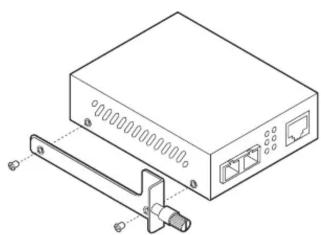
natural_image
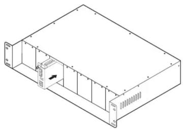
Technical line drawing of a device with ports and connectors (no text or symbols)- Remove the front metal plate of the slot on the chassis, then carefully slide the media converter into the slot and lock it tightly with the locking knob.
natural_image
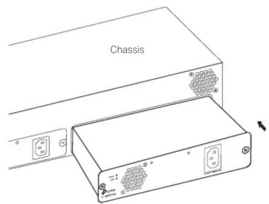
Isometric line drawing of a rectangular electronic device with internal components and mounting flanges (no text or symbols)Step 2: (Optional) Install the Redundant Power Supply Module
Remove the protective cover on the power supply module slot of the chassis. Then gently push in the module and plug it solidly into the connector.
Step 3: Mount the Chassis on the Rack
Note:
- The chassis supports EIA standard-sized, 19-inch racks.
- For security reasons, it is recommended to install the chassis as shown below.
Fasten the chassis to the rack with screws through the holes of the brackets on each side.
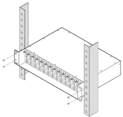
natural_image
Isometric technical drawing of a server rack unit with mounting flanges and internal components (no text or symbols)Step 4: Power On
- Electrically connect the Grounding Terminal on the rear panel of the chassis to ground via the ground cable.
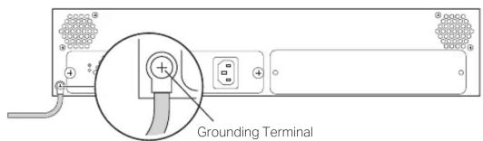
- Connect the chassis to the AC outlet using the provided power cord.
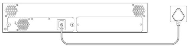
natural_image
Diagram of a device rear panel connected to a plug, showing internal components and wiring (no text or symbols)Panel Layout
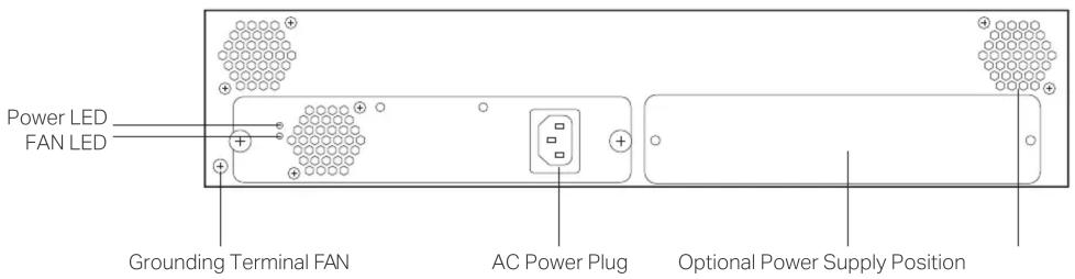
Note: An optional AC or DC power supply is available for installation in the optional power supply position.
LED Explanation

Power
On: Power on Off: Power off

FAN
On: The fans are working properly. Off: The fans are working abnormally.
Specifications
Specifications Environmental and Physical Specifications
| AC Power Supply | Input: 100–240 V ~ 50/60 Hz 1.8 A (Max)Output: 12 V, 6.25 A (Max)Ripple & Noise: < 180 mV (0 °C to 50 °C);< 250 mV (-10 °C to 0 °C) |
| DC Power Output per Slot | TL-MC1400: 9 V/0.6 ATL-FC1420: 5 V/0.6 A |
| Power, FANLED | |
| Dimensions(W×D×H) | 482 × 309 × 86 mm |
| YesHot-swappable | |
| YesOverload Protection |
| Operation Temperature | TL-MC1400: 0°C to 40°C (32°F to 104°F)TL-FC1420: 0°C to 50°C (32°F to 122°F) |
| Storage Temperature -40°C to 70°C (-40°F to 158°F) | |
| Operation Humidity 10% to 90% RH non-condensing | |
| Storage Humidity 5% to 90% RH non-condensing | |
Safety Information
- Keep the device away from water, fire, humidity or hot environments.
- Do not attempt to disassemble, repair, or modify the device. If you need service, please contact us.
- Avoid using this product during an electrical storm. There may be a remote risk of electric shock from lightning.
- The label is placed on the bottom surface of the product.
- Place the device with its bottom surface downward.
- The socket-outlet shall be installed near the equipment and shall be easily accessible.
Please read and follow the above safety information when operating the device. We cannot guarantee that no accidents or damage will occur due to improper use of the device. Please use this product with care and operate at your own risk.
EU Declaration of Conformity
TP-Link hereby declares that the device is in compliance with the essential requirements and other relevant provisions of directives 2014/30/EU, 2014/35/EU, 2009/125/EC, 2011/65/EU and (EU)2015/863. The original EU declaration of conformity may be found at https://www.tp-link.com/en/ce.


- Installation Guide
- Installation
- Step 1: Install the Media Converters in the Chassis
- Step 2: (Optional) Install the Redundant Power Supply Module
- Step 3: Mount the Chassis on the Rack
- Step 4: Power On
- Panel Layout
- LED Explanation
- Power
- FAN
- Specifications
- Safety Information
- EU Declaration of Conformity
Marke : TP-LINK
Modell : TL-FC1420
Kategorie : Audio-/Video-Konverter