TPI-PRO-DVI-4 - Schalter AMX - Kostenlose Bedienungsanleitung
Finden Sie kostenlos die Bedienungsanleitung des Geräts TPI-PRO-DVI-4 AMX als PDF.


Benutzerfragen zu TPI-PRO-DVI-4 AMX
0 Frage zu diesem Gerät. Beantworten Sie die, die Sie kennen, oder stellen Sie Ihre eigene.
Eine neue Frage zu diesem Gerät stellen
Laden Sie die Anleitung für Ihr Schalter kostenlos im PDF-Format! Finden Sie Ihr Handbuch TPI-PRO-DVI-4 - AMX und nehmen Sie Ihr elektronisches Gerät wieder in die Hand. Auf dieser Seite sind alle Dokumente veröffentlicht, die für die Verwendung Ihres Geräts notwendig sind. TPI-PRO-DVI-4 von der Marke AMX.
BEDIENUNGSANLEITUNG TPI-PRO-DVI-4 AMX
Overview
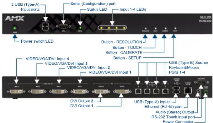
The TPI-PRO-DVI Presentation Interface with DVI displays up to 4 fully-scalable video windows, each supporting Composite, S-Video, Component, VGA and DVI signals on third party touch monitors (FIG. 1).
text_image
2 USB (Type-A) Input ports Serial (Configuration) port Status LED Input 1-4 LEDs Power switch/LED Button - RESOLUTION Button - TOUCH Button - CALIBRATE Button - SETUP VIDEO/VGA/DVI Input 4 VIDEO/VGA/DVI Input 3 VIDEO/VGA/DVI Input 2 VIDEO/VGA/DVI Input 1 USB (Type-B) Source Keyboard/Mouse Ports 1-4 DVI Output 2 DVI Output 1 USB (Type-A) Inputs Ethernet (RJ-45) port Audio (Stereo) Output RS-232 Touch Input port Power ConnectorFIG. 1 TPI-PRO-2/4-DVI (TPI-PRO-4-DVI shown)
There are two versions of the TPI-PRO-DVI available:
• The TPI-PRO-DVI-2 (FG2275-112) supports up to two DVI inputs.
• The TPI-PRO-DVI-4 (FG2275-114) supports up to four DVI inputs.
Product Specifications
The following table lists the specifications for the TPI-PRO-DVI-2 and TPI-PRO-DVI-4. Note that the primary difference between the TPI-PRO-DVI-2 and TPI-PRO-DVI-4 is in the number of inputs. In terms of functionality and specifications, they are otherwise identical.
The specifications listed below apply to both versions, unless specifically noted.
TPI-PRO-DVI Specifications
| • Power Requirements: | • Constant current draw: 2.6 A @ 12 VDC• The PSN6.5 Power Supply (FG423-41 - not included) is recommended, to accommodate all possible configurations and respective power draws. | |
| • Memory: • 256 MB | SDRAM• 256 MB disk memory | |
| • Supported Video Resolutions: | Input DVI Video:• up to 1920 x 1200• single-link DVI onlyInput Component Video:• NTSC 480i, 480p• PAL 576i, 576p• 720p, 1080i, 1080p | Input Composite Video and S-Video:• N T S C M / J• N T S C 4 . 4 3• PAL B/D/I/G/H• P A L 6 0• PAL M / N / Nc• SECAM B/D/G/K/L |
| • Supported Audio Sample Rates: | 48000Hz, 44100Hz, 32000Hz, 24000Hz, 22050Hz, 16000Hz, 12000Hz, 11025Hz, and 8000Hz. | |
| Front Panel Components | ||
| • Powerswitch/LED: | Toggles the unit off and on.• Light Off: Power to the unit is either not plugged in, below approximately 10VDC, above approximately 19VDC, or cross-wired.• Constant Green: Power to the unit is within nominal voltage limits (between 10VDC and 19VDC, approximately), the unit is on, and all internal power supplies are operating normally.• Constant Yellow: Power to the unit is within nominal voltage limits (between 10VDC and 19VDC, approximately) and the unit has been turned off by pressing the power switch for more than two seconds.• Flashing Yellow: Power to the unit is within nominal voltage limits (between 10VDC and 19VDC, approximately), but one or more of the internal power supplies are not operating correctly. The unit needs to be serviced. Contact AMX Technical Support for further instructions. | |
| • USB Type-A Host ports: | 2 USB Type A ports for connecting up to one annotation touch monitor and up to one keyboard/mouse.Note: Do not use a USB hub to connect multiple USB devices to the PI. | |
| • Serial port: | DB9 connector (male) connects to a DB9 serial port on a PC, for serial communication. | |
| • Status LED: • Constant ON: No communication with the NetLinx Master• Blinking: In communication with the NetLinx Master | ||
| • Input LEDs: Yellow LEDs Indicate a valid input signal on each source input (1-4 on the TPI-PRO-DVI-4, 1-2 on the TPI-PRO-DVI-2). | ||
| • Buttons: Four white buttons provide access to the following configuration options:• RESOLUTION: Opens a screen used to select the TPI-PRO-DVI output video signal resolution, ranging from 640 x 480@60Hz to 1920 x 1200@60Hz.Note: This output resolution setting must not be greater than the resolution on the connected panel.• TOUCH: Opens the Panel Information page, where you can select from a series of serial touch panel drivers, and select the driver that corresponds to the serial touch panel connected to the TPI-PRO-DVI (via the TOUCH INPUT connector).• CALIBRATE: Opens the Calibration page, displaying a series of crosshairs. These crosshairs are used to calibrate the touch device being used.• SETUP: Opens the TPI-PRO-DVI firmware setup menu. | ||
TPI-PRO-DVI Specifications (Cont.)
| Rear Panel Components | ||
| • DVI-I Inputs: DVI-I input connectors, one per input source (1-4 on the TPI-PRO-DVI-4, 1-2 on the TPI-PRO-DVI-2).Each input connector supports DVI, VGA graphics, S-video, composite, and component video. | ||
| • DVI-I Outputs: 2 DVI-I (VESA/EIA compatible) output connectors. Both outputs support DVI-D and analog VGA (RGBHV) outputs.• Maximum output resolution = 1920 x 1200@60 Hz• Default output resolution = 1280 x 1024@60 HzNote: Refer to the TPI-PRO-DVI Operation/Reference Guide for a listing of Supported Pixel Display and Refresh Rates.These connectors display video feeds, G4 graphics and external windowed video/graphics inputs.The DVI-I Outputs can be connected to either:• The touch-panel control display• The public-view non-touch monitorNote: The TPI-PRO-DVI does not provide Component (YPbPr) or Interlaced outputs. | ||
| • Source TOUCH, KEYBOARD/MOUSE USB ports: | 2 or 4 USB Type-B device ports, one per source computer—for source USB Touch Monitor, mouse/keyboard control (1-4 on the TPI-PRO-DVI-4, 1-2 on the TPI-PRO-DVI-2).Note: Do not use a USB hub to connect multiple USB devices to the TPI. | |
| • Host USB Touch Monitor KEYBOARD/MOUSE USB ports: | 2 USB Type-A ports that can be used for a keyboard, mouse, external storage unit, or USB-capable touch panel interface.Note: Do not use a USB hub to connect multiple USB devices to the TPI. | |
| • ETHERNET 10/100 port: | RJ-45 port provides 10/100 Mbps communication with the NetLinx Master (via ICSP protocol over Ethernet).• The Ethernet port automatically negotiates the connection speed (10 Mbps or 100 Mbps), and whether to use half duplex or full duplex mode.• This communication is reflected via the front ICSP LED. | |
| • TOUCH INPUT port: | RS-232 (DB9) 9-pin serial port provides connectivity to a pointer device (i.e. touch screen) that requires a serial connection. | |
| • AUDIO OUT connector: | 3.5mm mini-jack provides stereo output - for use with line-level (0.707 VRMS) non-amplified stereo output only. | |
| • Power connector: 2-pin 3.5 mm mini-Phoenix connector. | ||
| • Serial Touch Drivers: | Go to http://www.amx.com//techdocs/TPI-PRO.Supported.Touch.Monitors.xls to view/download the most recent List of Touch Monitors and USB Touch Drivers Tested with the TPI-PRO-DVI (including the most current listing of tested serial touch panel drivers). | |
| • USB Drivers: USB Touch drivers are automatically loaded when the USB Touch Monitor is detected. | ||
| • Button Assignments: | Button assignments can be modified in TPD4 (not on the TPI-PRO-DVIs.)• Button channel range: 1 - 4000 button push & feedback (per address port)• Button variable text range: 1 - 4000 (per address port)• Button states range: 1 - 256 (General Button; 1 = Off State, 2 = On State)• Level range: 1 - 600 (Default level value 0-255, can be set up to 1-65535)• Address port range: 1 - 100 | |
| • Communication/Programming: | Master communication and programming is available via an Ethernet connection. There are several methods of TPI-PRO-DVI communication and programming available, including DHCP, Static IP, URL, Listen, Auto, NPD (UPD) and URL (UPD).Refer to the TPI-PRO-DVI Operation/Reference Guide for details. | |
| • Enclosure: Metal with black matte finish | ||
| • Operating/Storage Environment: | • Operating Temperature: 0°C (32°F) to 40°C (104°F)• Operating Humidity: 5% to 85% RH Non-Condensing• Storage Temperature: -10°C (14°F) to 70°C (158°F)• Storage Humidity: 0% to 85% RH Non-Condensing | |
| • Dimensions (HWD): | • 1.72" x 17.00" x 10.54"(4.37 cm x 43.18 cm x 26.77 cm) | |
| • Weight: | 8.25 lbs (3.74 kg) | |
| • Certifications: | • RoHS• FCC (Class B) | • CE• IEC / EN 6 0 9 5 0 |
| • Included Accessories: | • 2-pin PWR connector (41-5025)• Assembly Kit - Four screws and washers (KA0001)• Rack Ear brackets (60-0900-03) | |
| • Other AMX Equipment: | • PSN6.5: Power Supply with 3.5 mm mini-Phoenix connector (FG423-41)• CC-DVI-5BNCM: DVI-to-5 BNC Male Adapter Cable (FG10-2170-08)• CC-DVI-RCA3M: DVI-to-3 RCA Male Adapter Cable (FG10-2170-09)• CC-DVI-SVID: DVI-to-S-Video Adapter Cable (FG10-2170-10)• CC-DVIM-VGAF: DVI-to-VGA Adapter Cable (FG10-2170-13) | |
Before You Start
The TPI-PRO-DVI has been factory setup with specific touch panel pages. The first splash screen that appears indicates the TPI is receiving power, loading firmware, and preparing to display the default touch panel page.
When the panel is ready, the AMX Splash Screen is replaced by the initial Panel Setup page.
- Verify you are using the latest NetLinx Master firmware.
- Verify you are using the latest TPI-PRO-DVI firmware.
- Verify the NetLinx Studio program you are using is version 2.8 or higher.
- Verify the TPDesign4 program you are using is version 2.11 or higher.
Installation/Safety Instructions
- Connect the unit only to a properly-rated supply circuit.
- DO NOT stand other units directly on top of the TPI-PRO-DVI when it is rack mounted, as this will place excessive strain on the mounting brackets.
- ALWAYS ensure that the rack enclosure is adequately ventilated.
Adequate ventilation is critical for proper operation of the TPI-PRO-DVI.
The TPI-PRO-DVI uses the bottom cover as a heat sink. In most installations it will be necessary to have some amount of airflow across the bottom cover.
It is good practice to leave 1 RU of empty space above and below the unit.
Placing the unit low in the rack, using vented spacer panels and keeping other heat-generating equipment away from the unit can also be beneficial.
Depending on the rack enclosure and the surrounding air temperature, it may also be necessary to incorporate rack fans to increase air flow across the bottom of the unit.
The TPI-PRO-DVI occupies one rack unit in a standard 19" equipment rack.
The included mounting brackets can be rotated 90^ in any direction to accommodate several different mounting options, including tabletop, under/over the table, and vertical wall mounting.
Connections Overview
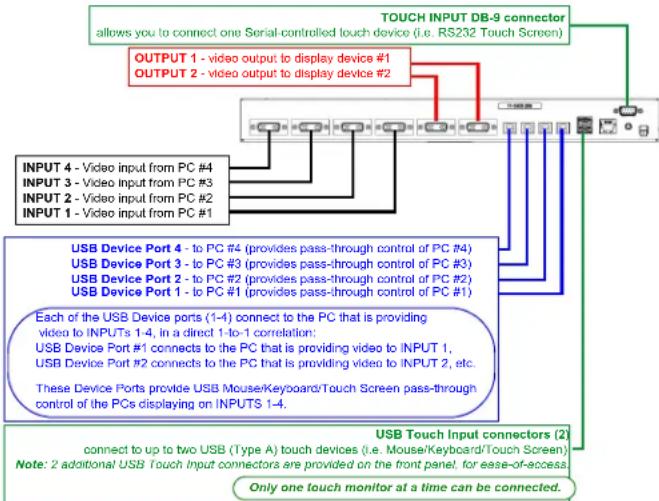
FIG. 2 illustrates how all of the basic connections on the TPI-PRO-DVI are used in a basic installation:
flowchart
graph TD
    A["OUTPUT 1 - video output to display device #1"] --> B["TOUCH INPUT DB-9 connector"]
    C["OUTPUT 2 - video output to display device #2"] --> B
    D["INPUT 4 - Video input from PC #4"] --> B
    E["INPUT 3 - Video input from PC #3"] --> B
    F["INPUT 2 - Video input from PC #2"] --> B
    G["INPUT 1 - Video input from PC #1"] --> B
    H["USB Device Port 4 - to PC #4 (provides pass-through control of PC #4)"] --> B
    I["USB Device Port 3 - to PC #3 (provides pass-through control of PC #3)"] --> B
    J["USB Device Port 2 - to PC #2 (provides pass-through control of PC #2)"] --> B
    K["USB Device Port 1 - to PC #1 (provides pass-through control of PC #1)"] --> B
    L["Each of the USB Device ports (1-4) connect to the PC that is providing video to INPUTs 1-4, in a direct 1-to-1 correlation: USB Device Port #1 connects to the PC that is providing video to INPUT 1, USB Device Port #2 connects to the PC that is providing video to INPUT 2, etc. These Device Ports provide USB Mouse/Keyboard/Touch Screen pass-through control of the PCs displaying on INPUTS 1-4."] --> M["USB Touch Input connectors (2) connect to up to two USB (Type A) touch devices (i.e. Mouse/Keyboard/Touch Screen)"]
    N["Note: 2 additional USB Touch Input connectors are provided on the front panel, for ease-of-eccess. Only one touch monitor at a time can be connected."] --> M
FIG. 2 TPI-PRO-DVI - Basic Wiring Connections
Cable Details and Pinouts
Refer to the TPI-PRO-DVI Operation/Reference Guide.
Startup Routine and Initial Panel Response
- Discharge any acquired static electricity by touching a grounded metal object.
- Verify the rear connections are secure and active.
-
Connect the 12VDC Power Supply to the PWR connector on the rear panel.
The TPI will power ON and initialize the startup routine when the power supply is connected.
Note: Once power is applied, use the Power button to toggle the unit off and on. -
After the startup routine, the connected touch monitor displays one of two possible screens:
-
If the TPI's output resolution matches that of the touch monitor, continue by setting the touch drivers associated with the touch monitor.
Refer to the Setting the Touch Drivers (Serial Touch Monitors Only) section of the TPI-PRO-DVI Operation/Reference Guide for details.
- If the TPI's output resolution does not match the resolution of the connected touch monitor, you must set the output resolution of the TPI to match the touch monitor.
Note: An "OUT OF RANGE" message is often generated by the touch monitor. Some monitors will not display a message, but will appear blank instead.
Setting the Output Resolution
The TPI's output resolution must match the output pixel resolution and refresh rate set on the connected touch monitor.
• The default output resolution is 1280 x 1024 @ 60Hz.
• The maximum output resolution is 1920 x 1200 @ 60 Hz.
Note: The TPI-PRO-DVI does not provide Component (YPbPr) or Interlaced outputs.
- Use the RESOLUTION pushbutton to alter the outgoing resolution to match the output pixel resolution and refresh rate set on the connected touch monitor.
-
Press the RESOLUTION pushbutton to open the Resolution Setup page.
-
Press the RESOLUTION button again to cycle through the available output resolution settings.
-
Every consecutive button push cycles the output resolution to the next highest setting.
- Double-push the RESOLUTION button to return to the previous setting.
-
For a listing of available pixel display and refresh rates, refer to the TPI-PRO-DVI Operation/Reference Guide.
-
The message "Please wait, loading new resolution..." indicates that the new resolution setting is being saved. Do not remove power while the new settings are being saved.
-
Once your resolution is selected, you can use the outer screen area lines on the Resolution Setup page to adjust your monitor's visible screen area.
- This could involve using the monitor's video control to stretch and move the incoming video so that the borders follow the edges of the screen without disappearing.
-
There are normally 60 seconds before the resolution times-out, but you can press the front panel RESOLUTION button again to return to the previous resolution pattern and continue setting up the monitor.
-
Press and hold the RESOLUTION button to save the resolution setting and exit the Resolution Setup page.
Note: When the new output resolution is applied, there may be some shifting of the default Main page, as it was developed for 1280 × 1024 .
Setting the Touch Drivers (Serial Touch Monitors Only)
After matching the resolution between the TPI and panel/monitor, the next step is to select the necessary touch drivers from the driver set provided by the TPI.
- This step only applies to serial touch monitors, as USB monitors are automatically detected.
- The touch drivers are set when you connect the TPI to a touch monitor.
-
The default Touch Input Driver is EloTouch ^® .
• If you are using a non touch-enabled monitor, select NullTouch. -
Press the TOUCH pushbutton on the front panel to open the Panel Information page.
-
Press the front panel TOUCH button to cycle through the list of available Touch Input Drivers.
Note: Go to http://www.amx.com/techdocs/TPI-PRO.Supported.Touch.Monitors.xls to view/download the most recent List of Touch Monitors and USB Touch Drivers Tested with the TPI-PRO-DVI (including the most current listing of tested serial touch panel drivers).
Verify that the selected Touch Input Driver matches the connected touch monitor.
Refer to the Available Pixel Display and Refresh Rates section in the TPI-PRO-DVI Operation/Reference Guide for a comprehensive list of Touch Monitors that have been tested with the TPI-PRO-DVI.
Calibrating the TPI-PRO-DVI
If the wrong touch driver is selected prior to the calibration process, press any of the front-panel pushbuttons to exit the calibration process and re-select another touch driver.
If you are using a non touch-enabled monitor, do not press the calibrate button.
Refer to the TPI-PRO-DVI Operation/Reference Guide for screen adjustment procedures.
Calibrating the TPI-PRO-DVI Using a USB Input
- Connect a USB cable from a touch panel to one of the Type-A USB ports on the front or back of the TPI.
- Press the POWER button on the front panel to reboot the TPI and allow the unit to detect the new hardware.
- Press the CALIBRATE button on the front panel to open the Calibration page.
-
Press the crosshairs to set the calibration points on the LCD.
-
After the "Calibration Successful." message appears, press anywhere to return to the Setup page. If the calibration fails, attempt to calibrate again. If unsuccessful, call AMX Tech Support.
Note: It is recommended that you calibrate the TPI before its initial use, after completing a firmware download, and after switching Touch Input Drivers (and touch devices.)
- Press the Protected Setup button (located on the lower-left of the panel page) to open the Protected Setup page.
- Enter 1988 in the Password field and press Done when finished.
- Press the on-screen Reboot button to cycle power to the TPI and incorporate the new settings. The touch monitor will go blank for a few seconds during the reboot process.
Calibrating the TPI-PRO-DVI Using a Serial Touch Panel
- Connect a DB9 cable from a touch panel to the DB-9 touch input connector on the back of the TPI.
- Press the POWER button on the front panel to reboot the TPI and allow the unit to detect the new hardware.
- Press the CALIBRATE button on the front panel. This process opens a calibration page that uses a series of crosshair coordinate intersections to calibrate the touch panel (using the newly selected touch driver). Note: If the wrong touch driver is selected prior to the calibration process, press any front panel button to exit the calibration process and re-select another touch driver.
- Press the crosshairs (on the Calibration page) to set the calibration points on the LCD.
- After the "Calibration Successful." message appears, press anywhere to return to the Setup page. If the calibration fails, return to the Protected Setup page and select another touch input driver.
Note: It is recommended that you calibrate the TPI-PRO-DVI before its initial use, after completing a firmware download, and after switching touch input drivers (and touch devices.)
- Press the Protected Setup button (located on the lower-left of the panel page) to open the Protected Setup page.
- Enter 1988 into the Keypad's password field and press Done when finished.
- Press the on-screen Reboot button to cycle power to the TPI and incorporate the new settings. The touch monitor goes blank for a few seconds during the reboot process. You can also use a mouse to press the on-screen Reboot button.
- Upon start-up, press anywhere on the screen to return to the Protected Setup page and begin defining the communication properties (refer to the TPI-PRO-DVI Operation/Reference Guide for information).
Additional Documentation
For detailed cabling, installation, configuration, programming, and operating instructions, refer to the TPI-PRO-DVI Operation/Reference Guide available on-line at www.amx.com.