
SBP-302F - Nicht kategorisiert Hanwha - Kostenlose Bedienungsanleitung
Finden Sie kostenlos die Bedienungsanleitung des Geräts SBP-302F Hanwha als PDF.


| Produkttyp | Wandhalterung |
| Modell | SBP-302F |
| Marke | Hanwha |
| Abmessungen (B x H x T) | 200 x 150 x 50 mm |
| Gewicht | 0,5 kg |
| Material | Aluminium |
| Farbe | Schwarz |
| Kompatibilität | Hanwha Überwachungskameras |
| Montageart | Wandmontage |
| Lieferumfang | Halterung, Schrauben, Dübel, Montageanleitung |
| Einsatzbereich | Innen- und Außenbereich |
| Besonderheiten | Schwenk- und neigbar |
| Garantie | 2 Jahre |
Häufig gestellte Fragen - SBP-302F Hanwha
Benutzerfragen zu SBP-302F Hanwha
0 Frage zu diesem Gerät. Beantworten Sie die, die Sie kennen, oder stellen Sie Ihre eigene.
Eine neue Frage zu diesem Gerät stellen
Laden Sie die Anleitung für Ihr Nicht kategorisiert kostenlos im PDF-Format! Finden Sie Ihr Handbuch SBP-302F - Hanwha und nehmen Sie Ihr elektronisches Gerät wieder in die Hand. Auf dieser Seite sind alle Dokumente veröffentlicht, die für die Verwendung Ihres Geräts notwendig sind. SBP-302F von der Marke Hanwha.
BEDIENUNGSANLEITUNG SBP-302F Hanwha
INSTALLATION INSTRUCTIONS
SBP-302F
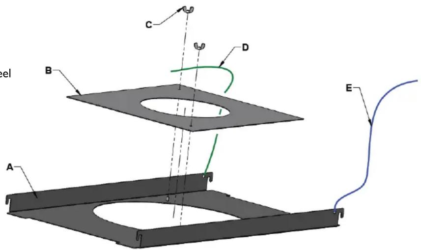
Ceiling Tile Support Plate with 12.85" diameter hole and optional 7.20" diameter hole for Hanwha products.
Supplied Parts
A. Support Plate with 12.85" diameter hole
B. Adapter Plate with 7.20" diameter hole
C. Wing Nut (2)
D. Tether—Camera to Support Plate
E. Tether—Support Plate to Structural Steel
STEP 1
Break off the shipping protection tabs on each side of the ceiling tile support plate. Flex each tab up and down until the tab breaks free.
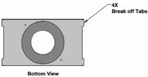
STEP 2
Place the ceiling tile support plate on the ceiling tile, being sure that the support ears are straddling the t-bars.
natural_image
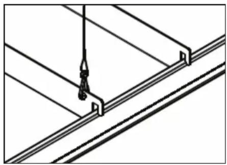
Pure technical line drawing of a structural connection with no text or symbolsSTEP 3
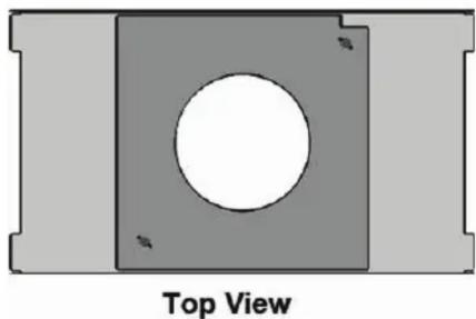
Mark the desired hole diameter.
Temporary remove the ceiling tile.
Cut the ceiling tile hole.
Replace the ceiling tile.
Place the ceiling tile support plate onto the ceiling tile.
natural_image
Top view diagram of a mechanical component with a circular hole and flanged base (no text or symbols)![Ø7.2in [183mm] 14.0in [356mm]](/content/2026/05/819939/images/96199771742ef454e1cf2bf3aa46e1bea7f138b6806053ca1bd9ff05f9ed5a5b.jpg)
Top View
natural_image
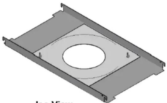
3D CAD model of a mechanical housing component with a central circular recess and mounting holes (no text or symbols)Iso View
![24.9in [631mm]](/content/2026/05/819939/images/b3bfd3b772272622774479b6afc4a0522d966bcf4a2f1d3923fa68a76062c5e3.jpg)
Front View
![4X Break off Tabs Ø 12.9in [326mm]](/content/2026/05/819939/images/45ba6c6794e30d2392eadf6cf75b11af4d404a4b96ef39072dff0807ffec8906.jpg)
Bottom View
Marke : Hanwha
Modell : SBP-302F
Kategorie : Nicht kategorisiert