
RB24ES - Staubsauger HITACHI - Kostenlose Bedienungsanleitung
Finden Sie kostenlos die Bedienungsanleitung des Geräts RB24ES HITACHI als PDF.


| Produkttyp | Zylinder-Staubsauger |
| Modell | RB24ES |
| Marke | Hitachi |
| Abmessungen (L x B x H) | 400 x 280 x 220 mm |
| Gewicht | 4,8 kg |
| Staubbehälter | beutellos, 2,0 l Fassungsvermögen |
| Filter | HEPA 13, waschbar |
| Leistung | 1200 Watt |
| Luftdurchsatz | 250 m³/h |
| Unterdruck | 25 kPa |
| Geräuschpegel | 76 dB(A) |
| Kabel | 6 m, automatischer Kabelschalter |
| Schlauch | 2 m, dehnbar |
| Zubehör | Bodendüse, Polsterdüse, Fugendüse, Bürste |
| Geeignet für | Hartboden, Teppich |
| Energieklasse (EU) | A (EEG 65) |
| Reinigung | Filter regelmäßig waschen, Behälter leeren |
| Sicherheit | Überhitzungsschutz, Thermosicherung |
| Ersatzteile | Filter, Bürsten, Düsen separat erhältlich |
| Reparatur | Kundendienst Hitachi, Ersatzteilverfügbarkeit 10 Jahre |
Häufig gestellte Fragen - RB24ES HITACHI
Benutzerfragen zu RB24ES HITACHI
0 Frage zu diesem Gerät. Beantworten Sie die, die Sie kennen, oder stellen Sie Ihre eigene.
Eine neue Frage zu diesem Gerät stellen
Laden Sie die Anleitung für Ihr Staubsauger kostenlos im PDF-Format! Finden Sie Ihr Handbuch RB24ES - HITACHI und nehmen Sie Ihr elektronisches Gerät wieder in die Hand. Auf dieser Seite sind alle Dokumente veröffentlicht, die für die Verwendung Ihres Geräts notwendig sind. RB24ES von der Marke HITACHI.
BEDIENUNGSANLEITUNG RB24ES HITACHI
Blower
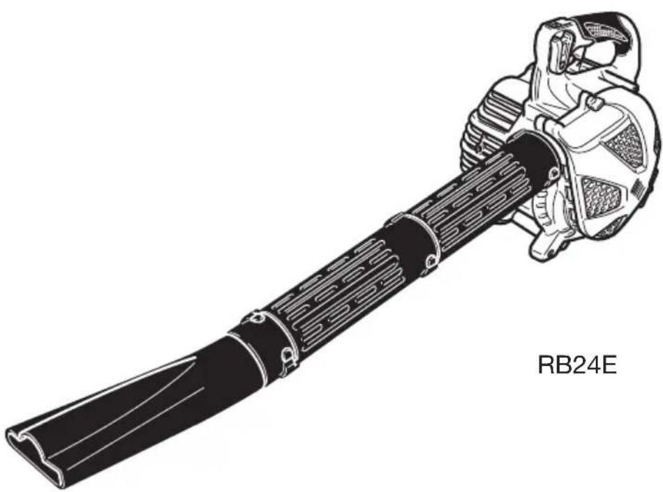
RB24E
natural_image
Technical line drawing of a mechanical device labeled RB24E, showing a blade and housing assembly (no text or symbols on the diagram itself)RB24E

Read the manual carefully before operating this machine.
Handling Instructions
natural_image
Illustration of a hand using a tool to adjust or install a mechanical component, with no visible text or symbols.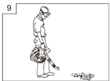
natural_image
Line drawing of a person standing with a backpack and holding a tool, next to a small pile of debris (no text or symbols)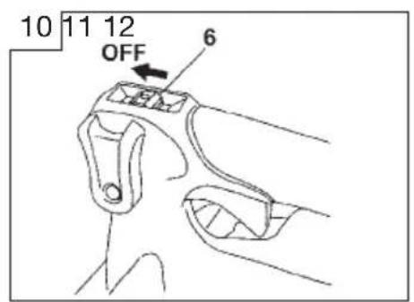
natural_image
Technical line drawing of a mechanical component with hands operating it (no text or symbols)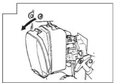
natural_image
Mechanical assembly diagram showing a valve mechanism with rotating components (no text or labels)
natural_image
Technical line drawing of a mechanical device with gears and adjustment knobs (no text or symbols)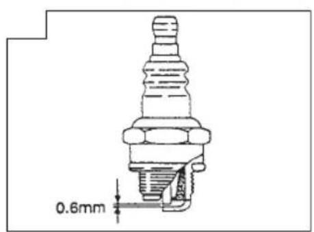
natural_image
Exploded view diagram of a mechanical assembly with components like screws, bolts, and a motor (no text or labels)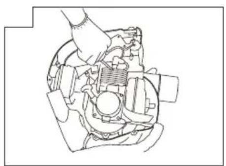
natural_image
Technical line drawing of a mechanical assembly with a hand operating a spring-loaded component (no text or symbols)Meanings of symbols.
NOTE! Some units do not carry them
| symbols⚠ WARNINGThe engine exhaust from this product contains chemicals known to the State of California to cause cancer, birth defects and other reproductive harm. | |
 | It is important that you read, fully understand and observe the following safety precautions and warnings. Careless or improper use of the unit may cause serious or fatal injury. |
 | Read, understand and follow all warnings and instructions in this manual and on the unit. |
 | Always wear eye, head and ear protectors when using this unit. |
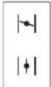 | Explains choke position. Upper sign indicates choke closed and the lower fully open. |
 | WARNING ⚠ DANGERKeep hands off from rotating fan. For vacuum, vacuum pipe and bag must be in place. For blower, dust cover must be securely installed. |
 | WARNING ⚠ DANGERHot surfaces; The muffler or catalytic muffler and surrounding cover may become extremely hot. Always keep clear of exhaust and muffler area, otherwise serious personal injury may occur. |
Index
What is what? 2
Warnings and safety instructions 3
Specifications 4
Assembly procedures 5
Operating procedures 5
Maintenance 5
Parts breakdown
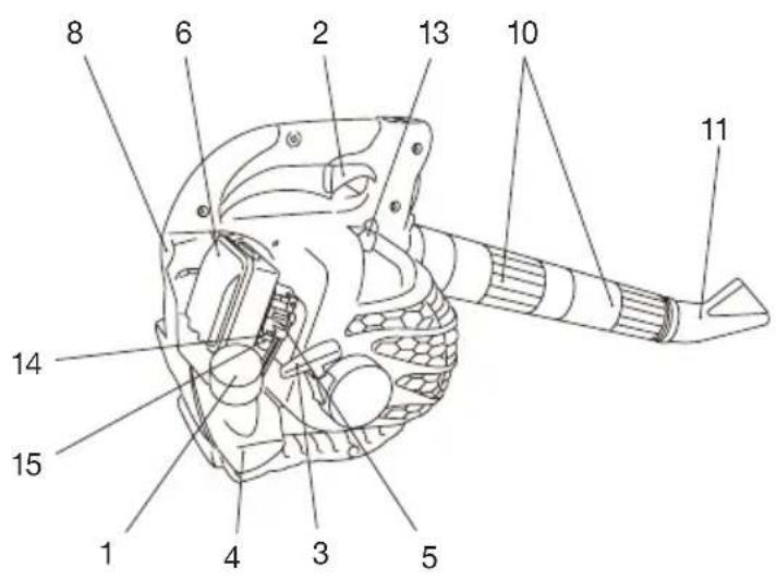
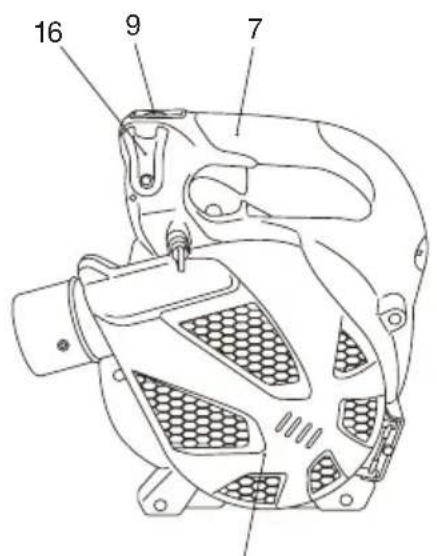
What is what?
Since this manual covers several models, there may be some difference between pictures and your unit. Use the instructions that apply to your unit.
- Fuel cap
- Throttle trigger
- Starter handle
- Fuel tank
- Carburetor
- Air cleaner
- Handle
- Suspension eyelet
- Ignition switch
- Straight pipe
- Fan-headed pipe
- Dust cover
- Spark plug
- Chock knob
- Priming bulb
- Cruise lever
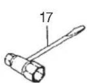
- Combi box spanner
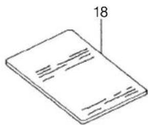
- Handling instructions
12
natural_image
Simple line drawing of a closed book with visible page lines and a label pointing to the page number 18 (no text or symbols on the book itself)Warnings and safety instructions
Operator safety
- IMPORTANT: A dust filter mask should be worn during operation.
- Always wear a safety face shield or goggles.
- Always wear heavy, long pants, boots and gloves. Do not wear loose clothing, jewelry, short pants, sandals or go barefoot. Secure hair so it is above shoulder length.
- Do not operate this tool when you are tired, ill or under the influence of alcohol, drugs or medication.
- Never let a child or inexperienced person operate the machine.
- Wear hearing protection. Pay attention to your surroundings. Be aware of any bystanders who may be signaling a problem. Remove safety equipment immediately upon shutting off engine.
- Never start or run the engine inside a closed room or building. Breathing exhaust fumes can kill.
- Keep handles free of oil and fuel.
- Keep hands away from moving part or heated area.
- Do not grab or hold the unit by the blow pipe.
- When the unit is turned off make sure the engine has stopped before the unit is set down.
- When operation is prolonged, take a break from time to time so that you may avoid possible whitefinger disease which is caused by vibration.
WARNING!
Antivibration systems do not guarantee that you will not sustain whitefinger dis-ease or carpal tunnel syndrome. Therefore, continual and regular users should monitor closely the condition of their hands and fingers. If any of the above symptoms appear, seek medical advice immediately.
WARNING!
If you are using any medical electric/electronic devices such as a pacemaker, consult your physician as well as the device manufacturer prior to operating any power equipment.
Unit / machine safety
- Inspect the entire unit/machine before each use. Replace damaged parts. Check for fuel leaks and make sure all fasteners are in place and securely tightened.
- Replace parts that are cracked, chipped or damaged in any way before using the unit/machine.
- Make sure the safety guard is properly attached.
- Keep others away when making carburetor adjustments.
- Use only accessories as recommended for this unit/machine by the manufacturer.
WARNING!
Never modify the unit/machine in any way. Do not use your unit/machine for any job except that for which it is intended.
Fuel safety
NOTE!
- Empty the fuel tank before storing the tool. Especially, in case of over three month storage, it is a must otherwise fuel may corrode causing carburetor damage. It is recommended that the fuel be emptied after each use. If fuel is left In the tank, store so fuel will not leak.
- Fuel contains highly flammable and it is possible to get the serious personal injury when inhaling or spilling on your body. Always pay attention when handling fuel. Always have good ventilation when handling fuel inside building.
- Mix and pour fuel outdoors and where there are no sparks or flames.
- Use a container approved for fuel.
- Do not smoke or allow smoking near fuel or the unit/machine or while using the unit/machine.
- Wipe up all fuel spills before starting engine.
- Move at least 3 m away from fueling site before starting engine.
- Stop engine before removing fuel cap.
- Store unit/machine and fuel in area where fuel vapors cannot reach sparks or open flames from water heaters, electric motors or switches, furnaces. etc.
Blowing safety
- Operate power equipment only at reasonable hours-not early in the morning or late at night when people might be disturbed. Comply with times listed in local ordinances. Usual recommendations are 9:00 a.m. to 5:00 p.m., Monday through Saturday,
- Never direct discharge of air toward bystanders nor allow anyone near the area of operation. Use care in directing discharge to avoid glass enclosures, automobiles, etc.
- Stay alert for uneven sidewalks, holes in terrain or other unstable condition when using the tool.
- Take all possible precautions when leaving the tool unattended such as stopping the engine.
- Never operate the tool without guards, blow pipes or other protective device in place. (If so equipped.)
- Keep others including children, animals, bystanders and helpers outside the 15m hazard zone. Stop the engine immediately if you are approached.
- Always keep the engine on the right side of your body. (Hand held blower only)
- Keep firm footing and balance. Do not over-reach.
- Keep all parts of your body away from the muffler.
• Always carry a first-aid kit when operating any power equipment.
Maintenance safety
- Maintain the unit/machine according to recommended procedures.
- Disconnect the spark plug before performing maintenance except for carburetor adjustments.
- Keep others away when making carburetor adjustments.
- Use only genuine HITACHI replacement parts as recommended by the manufacturer.
Transport and storage
- Carry the unit/machine by hand with the engine stopped and the muffler away from your body.
- Allow the engine to cool, empty the fuel tank, and secure the unit/machine before storing or transporting in a vehicle.
- Empty the fuel tank before storing the unit/machine, It is recommended that the fuel be emptied after each use. If fuel is left in the tank, store so fuel will not leak.
- Store unit/machine out of the reach of children.
- Clean and maintenance the unit carefully and store it in a dry place
- Make sure engine switch is off when transporting or storing.
If situations occur which are not covered in this manual, take care and use common sense. Contact HITACHI dealer if you need assistance. Pay special attention to statements preceded by the following words:
WARNING!
Indicates a strong possibility of severe personal injury or loss of life, if instructions are not followed.
CAUTION!
Indicates a possibility of personal injury or equipment damage, if instructions are not followed.
NOTE!
Helpful information for correct function and use.
Specifications
| MODEL | RB24E | |
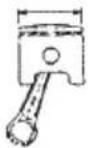 | Engine Size (ml) | 24 (1.46 cu. in) |
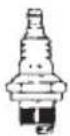 | Spark Plug | Champion CJ6 or NGK BMR7A or equivalent |
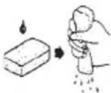 | Air Cleaner | Oiled foam filter system |
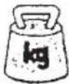 | Dry Weight (kg) | 5.0 |
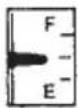 | Fuel Tank Capacity (Ω) | 0.6 |
| [3SY4] | Sound pressure level LpA (dB(A)) (EN27917) | By ANSI 68.0 By CEN 81.0 |
 | Sound power level LwA (dB(A)) | 104 |
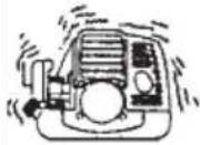 | Vibration level (m/s2)(ISO7916) | 11.2 |
NOTE : Equivalent noise level/vibration level are calculated as the time-weighted energy total for noise/vibration levels under various working conditions with the following time distribution : 1/2 idle, 1/2 racing. *All data subject to change without notice.
Assembly procedures
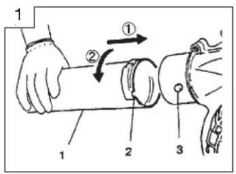
Blow pipes to main body (Fig. 1)
Inspect the main body and accessories.
Connect straight pipe (1) and other pipe(s) securely. (See page 1) Align groove () in straight pipe with projection (3) on blower housing (or another pipe) and slide the pipe onto the blower housing (or another pipe).
Rotate the pipe clockwise to lock it into place, then tighten the clamp band (if so equipped).
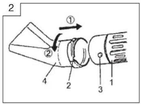
Fan headed pipe to straight pipe (Fig. 2)
- Align groove (1) on the fan headed pipe (2) and projection (3) on 2^nd straight pipe (4) and rotate the fan head in place.
NOTE! (RB24E, optional)
Vacuum attachment is offered as an optional kit which converts the hand-held blower into a vacuum cleaner.
For installation see RB-HVA vacuum manual.
NOTE ; Safety future
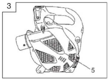
If you try to open the dust cover (5) when engine is running, it will automatically stop the engine. (Fig.3)
But never try to open the dust cover when engine is running even with this future, otherwise serious personal injury may occur.
Operating procedures.
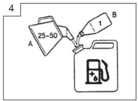
Fuel (Fig. 4)
WARNING!
This unit is equipped with a two-stroke engine. Always run the engine on fuel, which is mixed with oil.
Provide good ventilation, when fueling or handling fuel. Provide good ventilation, when fueling or handling fuel.
Fuel
• Always use branded 89 octane unleaded gasoline.
- Use genuine two-cycle oil or use a mix between 25:1 to 50:1, please consult the oil bottle for the ratio or HITACHI dealer.
- Only for the state of California at 50:1.
- If genuine oil is not available, use an anti-oxidant added quality oil expressly labeled for air-cooled 2-cycle engine use(JASO FC GRADE OIL or ISO EGC GRADE). Do not use BIA or TCW (2-stroke water-cooling type) mixed oil.
- Never use multi-grade oil (10 W/30) or waste oil.
- Always mix fuel and oil in a separate clean container.
Always start by filling half the amount of fuel, which is to be used. Then add the whole amount of oil. Mix (shake) the fuel mixture. Add the remaining amount of fuel.
Mix (shake) the fuel-mix thoroughly before filling the fuel tank.
Fueling
WARNING!
• Always shut off the engine before refueling.
- Slowly open the fuel tank, when filling up with fuel, so that possible over-pressure disappears.
- Tighten the fuel cap carefully, after fueling.
- Always move the unit at least 3 m (10 ft.) from the fueling area before starting.
- Do not smoke and/or allow flames or sparks near fuel when handling or filling fuel.
Before fueling, clean the tank cap area carefully, to ensure that no dirt falls into the tank. Make sure that the fuel is well mixed by shaking the container, before fueling.
Starting
CAUTION!
Do not start if the pipe is obstructed by the ground or any other object.
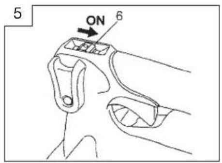
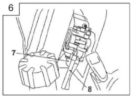
- Set ignition switch (6) to ON position. (Fig. 5) *Push priming bulb (7) several times so that fuel flows through the bulb or return pipe. (8) (If so equipped) (Fig. 6)
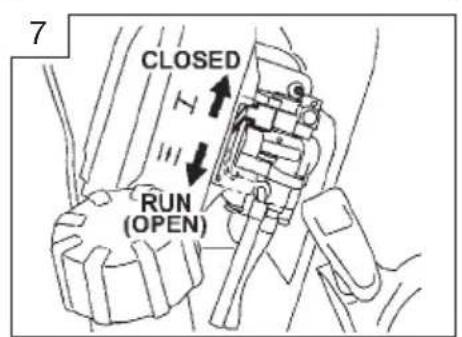
- Set choke lever to CLOSED position. (Fig. 7)
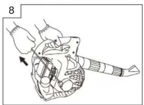
- Pull recoil starter briskly, taking care to keep the handle in your grasp and not allowing it to snap back. (Fig. 8)
- When you hear the engine want to start, return choke lever to RUN position (open). Then pull recoil starter briskly again.
WARNING!
- Never start or run the engine inside a closed room or building and/or near the inflammable liquid. Breathing exhaust fumes can kill.
- Do not allow the rope to snap back in and always hold the unit firmly.
NOTE!
If engine does not start, repeat procedures from 2 to 4.
- After starting engine, allow the engine about 2-3 minutes to warm up before subjecting it to any load.
Operating blower (Fig. 9)
WARNING!
Do not direct discharge of air toward people or pet.
- The unit should be operated in a well ventilated area.
- A low speed should be used to blow leaves and dry grass.
- A medium speed should be used to clean wet leaves and grass.
- A high speed should be used when moving gravel, dirt or other heavy materials.
WARNING!
- Never perform assembly or disassembly procedures with engine running or serious personal injury may result.
- Never touch muffler, spark plug, or other metallic parts while engine is in running or immediately after shutting off engine.
CAUTION!
This blower has been designed and adjusted to be used with all blowing pipes attached (See page 1). It must never be operated without the straight pipe, and blow head.
Stopping (Fig. 10)
Decrease engine speed and run at an idle for a few minutes, then turn off ignition switch.
Maintenance
MAINTENANCE. REPLACEMENT, OR RE-PAIR OF THE EMISSION CONTROL DE-VICES AND SYSTEM MAY BE PERFORMED BY ANY NONROAD ENGINE REPAIR ESTABLISHMENT OR INDIVIDUAL.
Carburetor adjustment (Fig. 11)
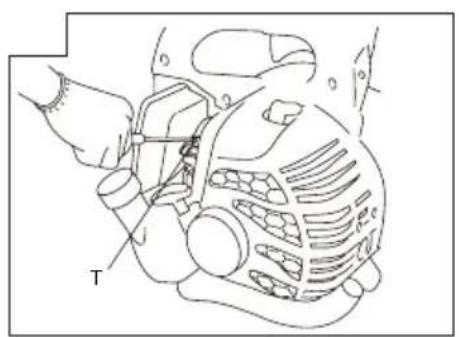
In the carburetor, fuel is mixed with air. When the engine is test run at the factory, the carburetor is adjusted. A further adjustment may be required, according to climate and altitude. The carburetor has one adjustment possibility:
T = Idle speed adjustment screw.
Idle speed adjustment (T)
To adjust, turn IDLE Adjustment Screw (T) in (clockwise) to increase engine speed, out (counterclockwise) to decrease engine speed.
Standard Idle rpm is 2800-3200rpm.
CAUTION!
The above adjusting procedure must be followed when adjustment is MADE or DAMAGE to engine will occur because of the incorrect condition.
NOTE!
Some models sold areas with strict exhaust emission regulation do not have high and low speed carburetor adjustments. Such adjustments may allow the engine to be operated outside of their emission compliance limits. For these models, the only carburetor adjustment is idle speed.
For models that equipped with low and high speed adjustments; carburetors are pre set at the factory Minor adjustments may optimize performance based on climate, altitude, etc. Never turn the adjustment screws in increments greater than 90 degrees, as engine damage can result from incorrect adjustment If you are not familiar with type of adjustment-assistance HITACHI dealer.
RECOMMENDATION:
CARBURETOR ADJUSTMENT NEEDS THE SKILL OF EXPERIENCED OR WELL TRAINED PEOPLE, IR IS RECOMMENDED TO TAKE THE UNIT TO HITACHI DEALER.
Air filter (Fig. 12)
The air filter must be cleaned from dust and dirt in order to avoid:
• Carburetor malfunctions.
- Starting problems.
• Engine power reduction.
- Unnecessary wear on the engine parts.
• Abnormal fuel consumption.
Remove the air cleaner cover by pushing and pulling back the tab on the top. (Fig. 12)
Cleaning the air filter
Clean the cleaner element every day or every 8 hours of operation. More frequent cleaning is recommended under very dusty conditions. Wash the element in liquid detergent and water. Squeeze the element to remove the dirt. Press the element in a dry rag until it is completely dry. Saturate the element in 2 cycle oil or the equivalent. Squeeze the element to distribute the oil completely and to remove any excess oil. Replace the element and install the cover. (Fig. 13)
Fuel filter (Fig. 14)
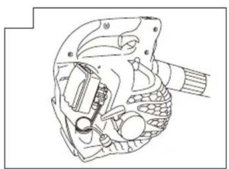
Drain all fuel from fuel tank and pull fuel filter line from tank. Pull filter element out of holder assembly and rinse element in warm water with detergent. Rinse thoroughly until all traces of detergent are eliminated. Squeeze, do not wring, away excess water and allow element to air dry.
NOTE!
If element is hard due to excessive dirt buildup, replace it.
Spark plug (Fig. 15)
The spark plug condition is influenced by:
- An incorrect carburetor setting.
- Wrong fuel mixture (too much oil in the gasoline)
- A dirty air filter.
- Hard running conditions (such as cold weather).
These factors cause deposits on the spark plug electrodes, which may result in malfunction and starting difficulties. If the engine is low on power, difficult to start or runs poorly at idling speed, always check the spark plug first. If the spark plug is dirty, clean it and check the electrode gap. Re-adjust if necessary. The correct gap is 0.6 mm. The spark plug should be replaced after about 100 operation hours or earlier if the electrodes are badly eroded.
NOTE!
In some areas, local law requires using a resistor spark plug to suppress ignition signals. If this machine was originally equipped with resistor spark plug, use same type of spark plug for replacement.
Muffler (Fig. 16)
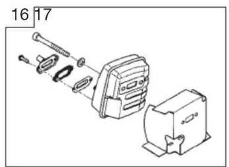
Remove the muffler and clean out any excess carbon from the exhaust port or muffler inlet every 100 hours of operation.
Cylinder (Engine cooling) (Fig. 17)
The engine is air cooled, and air must circulate freely around engine and over cooling fins on cylinder head to prevent overheating.
Every 100 operating hours, or once a year (more often if conditions require), clean fins and external surfaces of engine of dust, dirt and oil deposits which can contribute to improper cooling.
NOTE!
Do not operate engine with engine shroud or muffler guard removed as this will cause overheating and engine damage.
Maintenance schedule
Below you will find some general maintenance instructions. For further information please contact HITACHI dealer.
Daily maintenance
- Clean the exterior of the unit.
- Check the dust cover for damage or cracks. Change the cover in case of impacts or cracks. (Hand held blower only)
- Check that nuts and screws are sufficiently tightened.
Weekly maintenance
- Check the starter, especially cord and return spring.
- Clean the exterior of the spark plug.
- Remove it and check the electrode gap. Adjust it to 0.6 mm, or change the spark plug.
- Clean the cooling fins on the cylinder and check that the air intake at the starter is not clogged.
- Clean the air filter.
Monthly maintenance
- Rinse the fuel tank with gasoline.
- Clean the exterior of the carburetor and the space around it.
- Clean the fan and the space around it.
NOTE!
When ordering the parts to your nearest dealer, please use the item No. showing on the parts breakdown section in this instruction.
RB24E
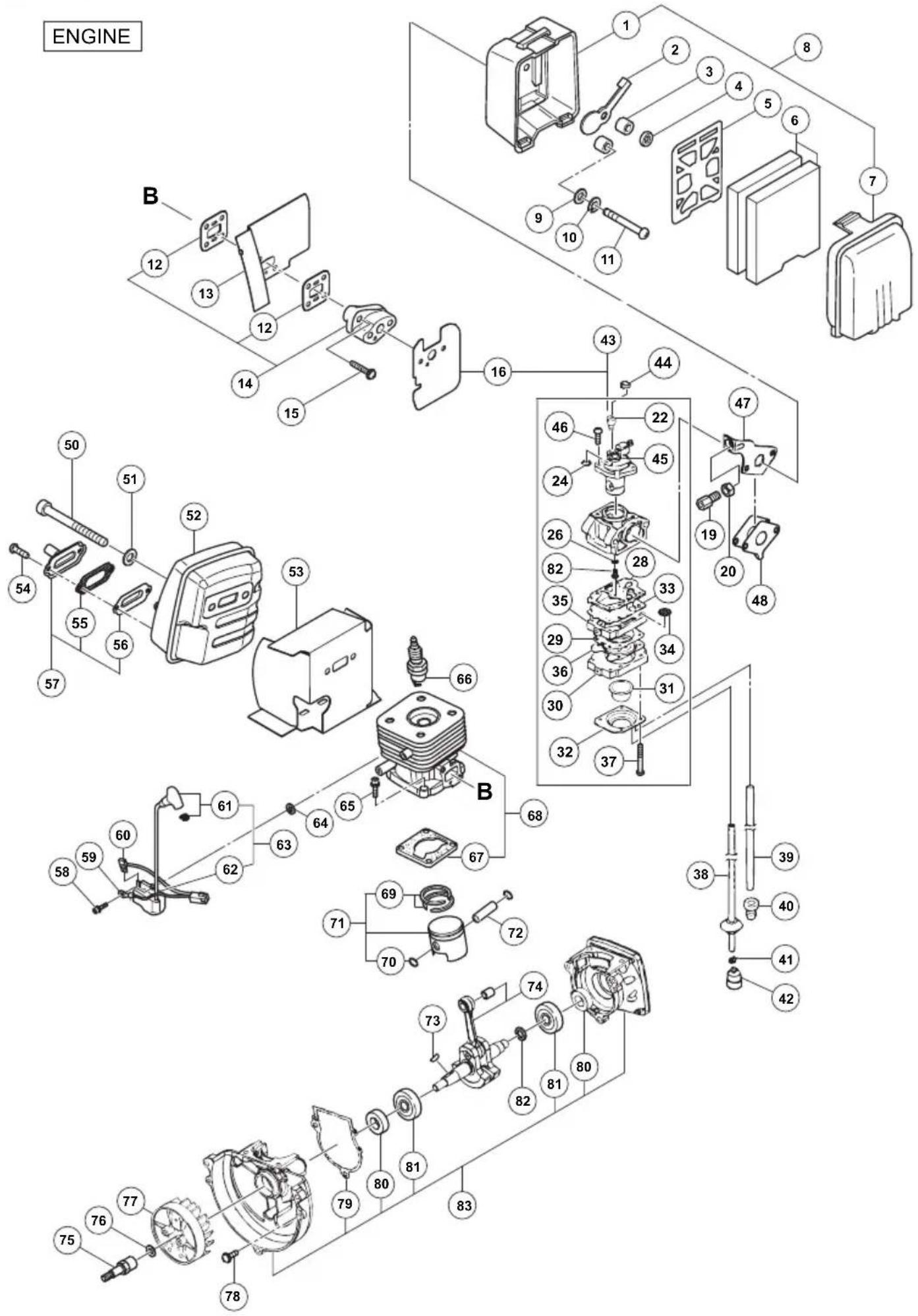
RB24E
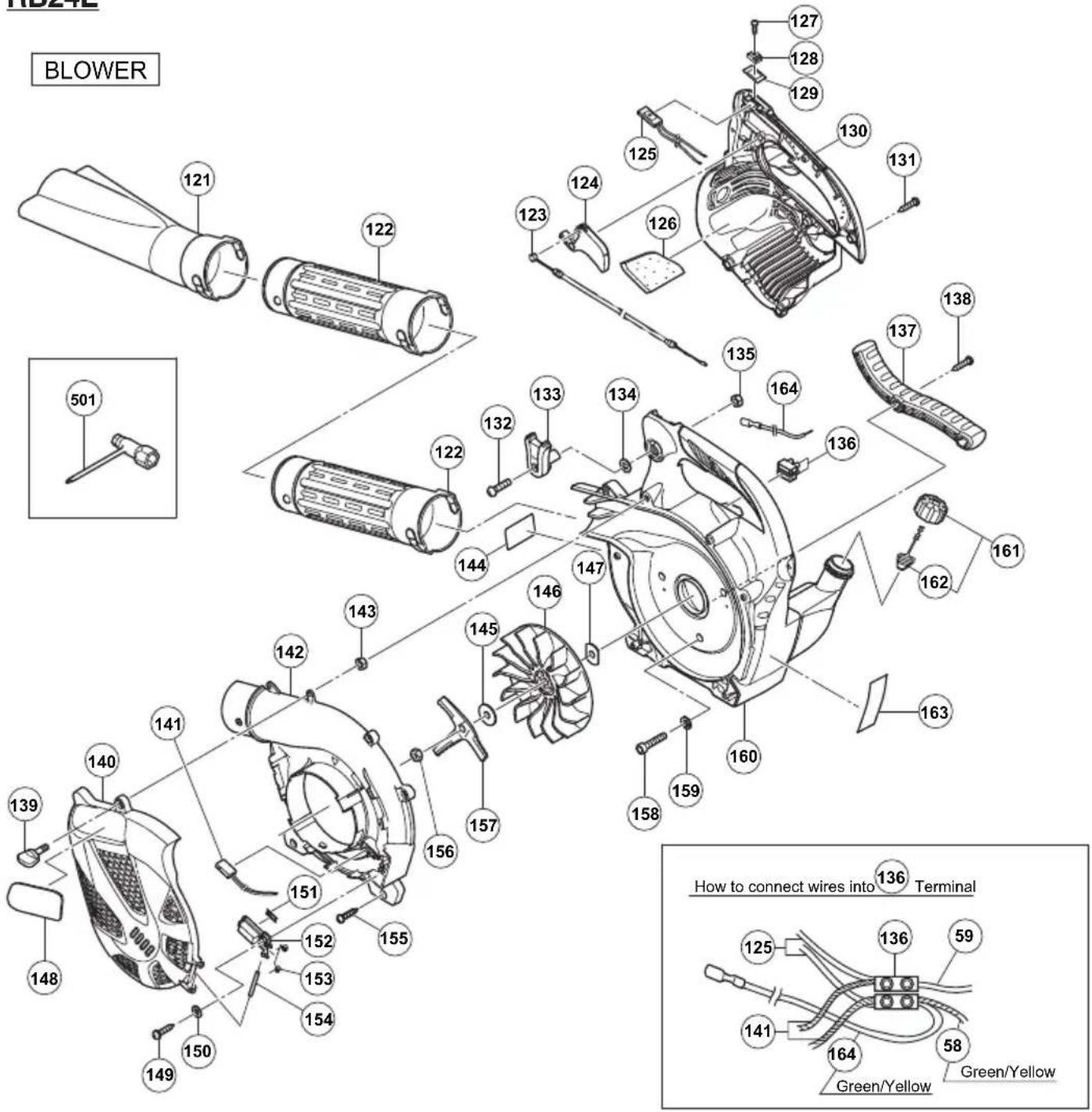
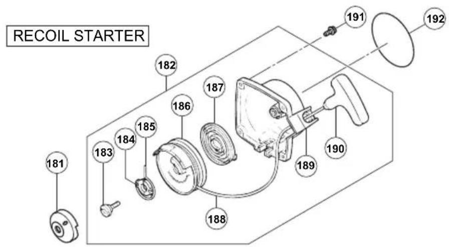
MEMO

Hitachi Koki Co., Ltd.

- Blower
- RB24E
- Meanings of symbols.
- Index
- What is what?
- Warnings and safety instructions
- Operator safety
- WARNING!
- Unit / machine safety
- Fuel safety
- NOTE!
- Blowing safety
- Maintenance safety
- Transport and storage
- CAUTION!
- Assembly procedures
- Blow pipes to main body (Fig. 1)
- Fan headed pipe to straight pipe (Fig. 2)
- NOTE! (RB24E, optional)
- NOTE ; Safety future
- Operating procedures.
- Fuel (Fig. 4)
- Fuel
- Fueling
- Starting
- Operating blower (Fig. 9)
- Stopping (Fig. 10)
- Maintenance
- MAINTENANCE. REPLACEMENT, OR RE-PAIR OF THE EMISSION CONTROL DE-VICES AND SYSTEM MAY BE PERFORMED BY ANY NONROAD ENGINE REPAIR ESTABLISHMENT OR INDIVIDUAL.
- Carburetor adjustment (Fig. 11)
- Idle speed adjustment (T)
- RECOMMENDATION:
- Air filter (Fig. 12)
- Cleaning the air filter
- Fuel filter (Fig. 14)
- Spark plug (Fig. 15)
- Muffler (Fig. 16)
- Cylinder (Engine cooling) (Fig. 17)
- Maintenance schedule
- Daily maintenance
- Weekly maintenance
- Monthly maintenance
- Hitachi Koki Co., Ltd.
Marke : HITACHI
Modell : RB24ES
Kategorie : Staubsauger