
V860IIO - Blitz GODOX - Kostenlose Bedienungsanleitung
Finden Sie kostenlos die Bedienungsanleitung des Geräts V860IIO GODOX als PDF.


| Produkttyp | TTL-Aufsteckblitz mit Li-Ion-Akku |
| Kompatible Kameras | Olympus/Panasonic (siehe Kompatibilitätsliste) |
| Leitzahl | 60 (m ISO 100, @200mm) |
| Blitzabdeckung | 10–100 mm (4/3-System) oder 20–200 mm (135-System), automatisch/manuell |
| Batterie | Li-Ion-Polymer, 11,1 V / 2000 mAh, aufladbar |
| Anzahl Vollblitze | ca. 650 |
| Wiederaufladezeit | < 1,5 Sekunden |
| Abmessungen (B × H × T) | 64 × 76 × 190 mm |
| Gewicht (ohne Akku) | 420 g |
| Gewicht (mit Akku) | 540 g |
| Blitzmodi | TTL, Manuell (M), Multi (Stroboskop) |
| Synchronisation | Hochgeschwindigkeitssynchronisation (bis 1/8000 s), 1. und 2. Vorhang |
| Kabellose Steuerung | 2,4 GHz Funk, Master/Slave, bis zu 100 m Reichweite |
| Kanäle | 32 (1–32) |
| Steuerbare Slave-Gruppen | 3 (A, B, C) |
| Blitzdauer | 1/300 bis 1/20000 Sekunden |
| Farbtemperatur | 5600 ± 200 K |
| Stromversorgung | Li-Ion-Akku, Ladezeit ca. 2,5 Stunden |
| Schutzfunktionen | Übertemperaturschutz, Fehlercodes E1/E2/E3/E9 |
| Wartung | Regelmäßig entstauben, nur durch autorisiertes Service-Center reparieren lassen |
| Garantie | 1 Jahr (außer Verbrauchsteile wie Blitzröhre) |
| Lieferumfang | Blitzgerät, Akku, Ladegerät, Ministaiv, Schutzhülle, Bedienungsanleitung |
| Sicherheitshinweise | Nicht in die Augen blitzen, nicht zerlegen, trocken halten, nicht in explosionsgefährdeter Umgebung verwenden |
Häufig gestellte Fragen - V860IIO GODOX
Benutzerfragen zu V860IIO GODOX
0 Frage zu diesem Gerät. Beantworten Sie die, die Sie kennen, oder stellen Sie Ihre eigene.
Eine neue Frage zu diesem Gerät stellen
Laden Sie die Anleitung für Ihr Blitz kostenlos im PDF-Format! Finden Sie Ihr Handbuch V860IIO - GODOX und nehmen Sie Ihr elektronisches Gerät wieder in die Hand. Auf dieser Seite sind alle Dokumente veröffentlicht, die für die Verwendung Ihres Geräts notwendig sind. V860IIO von der Marke GODOX.
BEDIENUNGSANLEITUNG V860IIO GODOX
TTL锂电机顶闪光灯
Pioneering Camera FlashTTL Li-ion
V860II ^ID
For Olympus/Panasonic
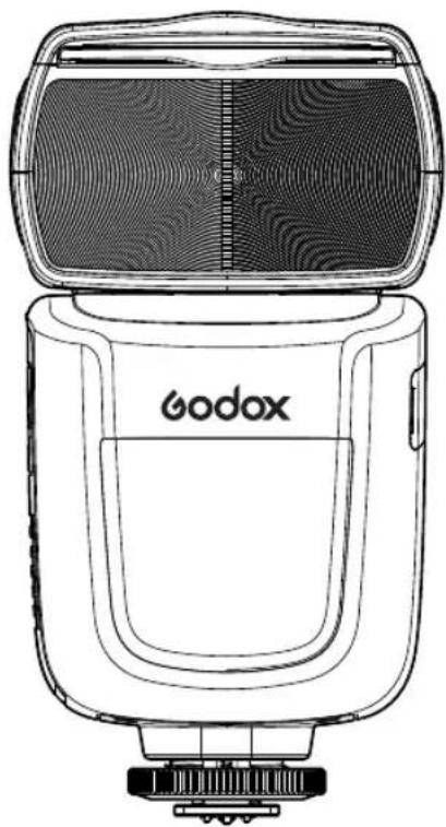
natural_image
Line drawing of a Godox brand flash unit with open lid and internal panel (no text or symbols on body)INSTRUCTION MANUAL
说明手册
中英文双语 / Chinese English Bilingual
神牛摄影器材有限公司
GODOX Photo Equipment Co., Ltd.
地址/Add: 深圳市宝安区福永镇福洲大道西新和村华发工业园A4栋
Building A4, Xinhe Huafa Industrial Zone, Fuzhou RD West, Fuyong
Town, Baoan District, Shenzhen 518103, China
电话/Tel: +86-755-29609320(8062) 传真/Fax: +86-755-25723423
邮箱/E-mail: godox@godox.com
http://www.godox.com
705-V862Z0-00
Made In China
FC CE RoHS 📄
在使用本产品之前:
请先仔细阅读本手册,以确保您能安全使用。请保存好本手册以备将来查询参考。
Before using this product:
Please read this user manual carefully in order to ensure your safety and the proper operation of this product. Keep for future reference.
Foreword
Thank you for purchasing this product.
This V8601IO camera flash applies to Olympus/Panasonic series cameras and is compatible with TTL autoflash. With this TTL compatible flash, your shooting will become simpler. You can easily achieve a correct flash exposure even in complex light-changing environments. This camera flash features:
• GN60 (m ISO 100, @200mm). 22 steps from 1/1 to 1/128.
• Pro 2000mAh Li-ion Battery —1.5s recycle—650 full power pops.
- Fully support Olympus/Panasonic series TTL camera flash. Workable as Master or Slave unit in a wireless flash group.
- Use dot-matrix LCD panel to make clear and convenient operations.
- With built-in 2.4GHz wireless remote system to support transmitting and receiving.
- Provided multiple functions, include HSS (up to 1/8000s), second-curtain sync, FEC, etc.
- Use optional FT-16S to adjust flash parameters & trigger the flash.
- Stable consistency and color temperature with good even lighting.
• Support with firmware upgrade.
For Your Safety
Always keep this product dry. Do not use in rain or in damp conditions.
This product contains high-voltage electronic parts. Touching the high-voltage circuit inside it may result in electric shock. Do not disassemble. Should repairs become necessary, this product must be sent to an authorized maintenance center.
⚠ Stop using this product if it breaks open due to extrusion, falling or strong hit. Otherwise, electric shock may occur if you touch the electronic parts inside it.
Do not fire the flash directly into the eyes (especially those of babies) within short distances. Otherwise visual impairment may occur. When taking pictures for babies, keep the flash unit at least 1 meter (3.3 feet) away from them. Using bounce flash to reduce light intensity is also recommended.
Do not use the flash unit in the presence of flammable gases, chemicals and other similar materials. In certain circumstances, these materials may be sensitive to the strong light emitting from this flash unit and fire or electromagnetic interference may result.
Do not leave or store the flash unit in places where the ambient temperature reads over 50°C (e.g. in automobile). Otherwise the electronic parts may be damaged.

Conventions used in this Manual
- This manual is based on the assumption that both the camera and camera flash's power switches are powered on.
- Reference page numbers are indicated by "p.***".
• The following alert symbols are used in this manual:
The Caution symbol gives supplemental information.
The Note symbol indicates a warning to prevent shooting problem.
Contents
27 Foreword
28 For Your Safety
31 Name of Parts
Body
Control Panel
LCD Panel
What's in the Box of V860IIO Kit?
What's in the Box of V860IIIO (only flash unit)?
Separately Sold Accessories
34 Battery
35 Attaching to a Camera
36 Power Management
36 Flash Mode: TTL Autoflash
FEC (Flash Exposure Compensation)
High-Speed Sync
Second-Curtain Sync
38 Flash Mode - M: Manual Flash
39 Flash Mode - Multi: Stroboscopic Flash
40 Wireless Flash Shooting: Radio (2.4G) Transmission
45 Other Applications
Wireless Control Function
Sync Triggering
Bounce Flash
Creating a Catchlight
ZOOM: Setting the Flash Coverage and Using the Wide Panel
Low Battery Indicator
48 C.Fn: Setting Custom Functions
48 Firmware Upgrade
49 Protection Function
50 Technical Data
51 Troubleshooting
52 Compatible Camera Models
52 Maintenance
Name of Parts
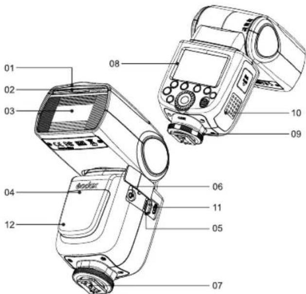
- Body
- Catchlight Panel
- Built-in Wide Panel
- Flash Head
- Optic Control Sensor
- Wireless Control Port
-
Sync Cord Jack
-
Hotshoe
- Dot-marix LCD Panel
- Lock Ring
- Battery Compartment
- USB Port
- Slave Flash Ready Indicator
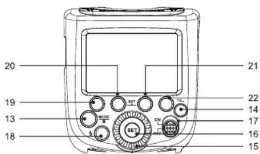
- Control Panel
Mode Selection Button / Lock button - < Z>Wireless Selection Button
- Select Dial
Set Button -
ON/OFF Power Switch
-
<⚡> Test Button / Flash Ready Indicator
-
Function Button 1
- Function Button 2
- Function Button 3
- Function Button 4
- LCD Panel
(1) TTL Autoflash
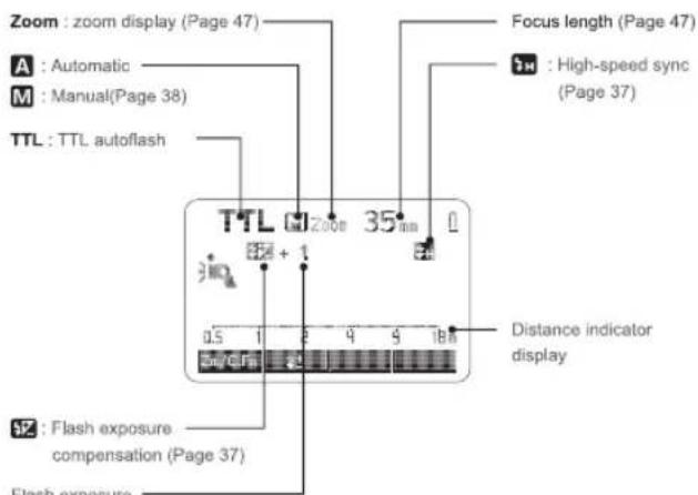
Flash exposure compensation amount
• The display will only show the settings currently applied.
- The functions displayed above function buttons 1 to 4, such as SYNC and ± , change according to settings' status.
- When a button or dial is operated, the LCD panel illuminated.
(2) M Manual Flash
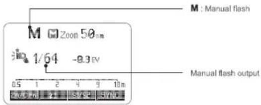
(3) Multi Stroboscopic Flash
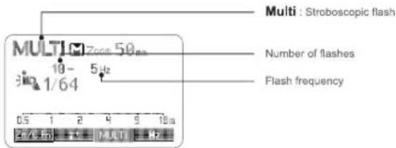
(4) Radio Transmission Shooting
- Master Unit
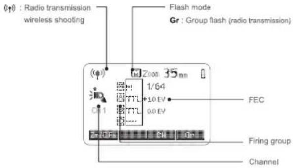
- Slave Unit
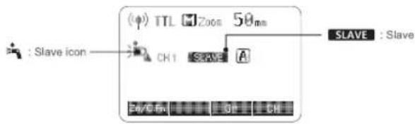
• What's in the Box of V860IIO Kit?
- Flash Unit 2. Li-ion Battery Pack 3. Battery Charger
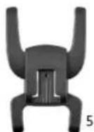
- Battery Charger Cable 5. Mini Stand
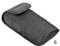
- Protection Case 7. Instruction Manual
- What's in the Box of V860IIIO (only flash unit)?
- Flash Unit 5. Mini Stand 6. Protection Case 7. Instruction Manual
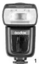
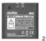
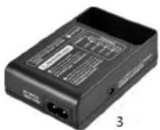
natural_image
Black electronic device with ports and labels, no visible text or symbols on body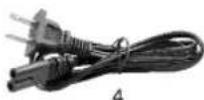
natural_image
Black textured fabric pouch with curled lid, no visible text or symbols• Separately Sold Accessories
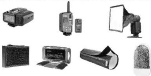
The product can be used in combination with the following accessories sold separately, so as to achieve best photography effects:
X1T-O wireless flash trigger, FT-16S power & trigger control, Mini softbox, White & Silver reflector, Honeycomb, Color gels, Snoot, etc.
natural_image
Collection of various photography equipment including a projector, radio, lamp, and camera filter (no visible text or symbols)Battery
- Features
- This flash unit uses Li-ion polymer battery which has long runtime. The available charge-and-discharge times are 500.
- It is reliably safe. The inner circuit is against overcharge, overdischarge, overcurrent, and short circuit.
- Take only 2.5 hours to fully charge the battery by using the standard battery charger.
- Cautions
- Do not short circuit.
- Do not expose to rain or immerse into water. This battery is not water proof.
- Keep out of reach of children.
- No over 24 hours' continuous charging.
- Store in dry, cool, ventilated places.
- Do not put aside or into fire.
- Dead batteries should be disposed according to local regulations.
- If the battery had ceased using for over 3 months, please make a full recharge.
- Loading and Unloading the Battery
natural_image
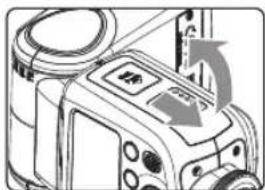
Diagram of a camera module with directional arrows indicating motion (no text or symbols)1 To load the battery, push the battery compartment cover downward and open it.
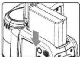
natural_image
Mechanical assembly diagram showing a component with a downward arrow indicating motion (no text or symbols present)2 According to the triangle sign on the battery pack, insert it into the compartment until a white knob locks the battery with a click sound.
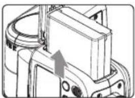
natural_image
Mechanical assembly diagram showing a component with a curved arm and housing (no text or symbols visible)3 To unload the battery, tap the white knob and the battery pack will pop out. Then close the compartment.
- Battery Level Indication
Make sure the battery pack is securely loaded in the flash. Check the battery level indication on the LCD panel to see the remaining battery level.
| Battery Level Indication | Meaning |
| 3 grids | Full |
| 2 grids | Middle |
| 1 grid | Low |
| Blank grid | Lower battery, please recharge it. |
| Blinking | The battery level is going to be used out immediately. And the flash will auto power off in 1 minute.Note: Please recharge the battery as soon as possible (within 10 days). Then, the battery can be used or be placed for long period. |
Attaching to a Camera
natural_image
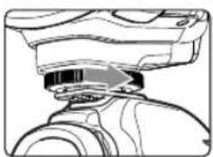
Technical line drawing of a mechanical component with no visible text or symbols1 Attach the Camera Flash.
- Slip the camera flash's mounting foot into the camera's hotshoe all the way.
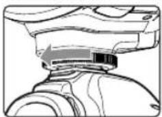
natural_image
Technical line drawing of a mechanical component with no visible text or symbols2 Secure the Camera Flash.
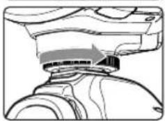
- Rotate the lock ring on the mounting foot until it locks up.
natural_image
Technical line drawing of a mechanical component with no visible text or symbols2 Detach the Camera Flash.
- Rotate the lock ring on the mounting foot until it is loosened.
Power Management
Use ON/OFF Power Switch to power the flash unit on or off. Turn off if it will not be used for an extended period of time. Setting as a master flash, it will turn the power off automatically after a certain period (approx. 90 seconds) of idle use. Pressing the camera shutter halfway or pressing any flash button will wake up the flash unit. Setting as a slave flash, it will enter sleep mode after 60 minutes (adjustable, 30 minutes by default) of idle use. Pressing any flash button will wake it up.
C.Fn Disabling Auto Power Off function is recommended when the flash is used off camera. (C.Fn-APO, Page 48)
C.Fn Slave Auto Power Off Timer is set to 60 minutes by default. Another option "30 minutes" is available. (C.Fn-Sv APOT, Page 48)
Flash Mode: TTL Autoflash
This flash has three flash modes: TTL, Manual (M), and Multi (Stroboscopic). In TTL mode, the camera and the flash will work together to calculate the correct exposure for the subject and the background. In this mode, multiple TTL functions are available: FEC, HSS, second curtain sync, etc.
* Press
TTL Mode
Press
- Press the camera release button halfway to focus. The aperture and effective flash range will be displayed in the viewfinder.
- When the shutter button is fully pressed, the flash will fire a pre-flash that the camera will use to calculate exposure and flash output the instant before the photo is taken.
FEC: Flash Exposure Compensation
With FEC function, this flash can adjust from -3 to +3 in 1/3rd stops. It is useful in situations where minor adjusting of the TTL system is needed based on the environment.
Setting FEC:
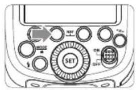
1 Press Function Button 2
< 12 >. The icon < 17 > and flash exposure compensation amount will be highlighted on the LCD panel.
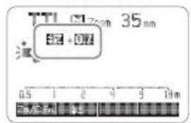
2 Set the flash exposure compensation amount.
- Turn the Select Dial to set the amount.
- "0.3" means 1/3 step, "0.7" means 2/3 step,
- To cancel the flash exposure compensation, set the amount to "+0".
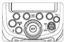
3 Press < SET > button again to confirm the setting.
High-Speed Sync
High Speed Sync (FP flash) enables the flash to synchronize with all camera shutter speeds. This is convenient when you want to use aperture priority for fill-flash portraits.
- Setting the flash to High-speed Sync mode when it is on the camera:
Press thebutton to turn on high-speed sync flash and is displayed. Then, adjust the camera's shutter to achieve high-speed sync flash.
- With high-speed sync, the faster the shutter speed, the shorter the effective flash range.
- Multi flash mode cannot be set in high-speed sync mode.
• Over-temperature protection may be activated after 15 consecutive high-speed sync flashes. - Try not to use high-speed sync flash, for using this function will reduce flash tube's service life.
Note: In the wireless remote control mode, using high-speed sync flash with Panasonic camera may occur out of sync.
Second-Curtain Sync
With a slow shutter speed, you can create a light train following the subject. The flash fires right before the shutter closes.
- Setting second-curtain sync:
Second-curtain sync function shall be set on the camera's menu. More details please refer to camera's instruction menu.
Flash Mode -- M: Manual Flash
The flash output is adjustable from 1/1 full power to 1/128th power in 1/3rd stop increments. To obtain a correct flash exposure, use a hand-held flash meter to determine the required flash output.
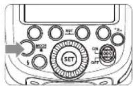
1 Press < MODE > button so that < M > is displayed.
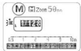
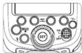
2 Turn the Select Dial to choose a desired flash output amount.
3 Press < SET > button again to confirm the setting.
Flash Output Range
The following table makes it easier to see how the stop changes in terms of f/stop when you increase or decrease the flash output. For example, when you decrease the flash output to 1/2, 1/2-0.3, or 1/2-0.7, and then increase the flash output to more than 1/2, 1/2+0.3, 1/2+0.7, and 1/1 will be displayed.
Figures displayed when reducing flash output level→
| 1/1 | 1/1-0.3 | 1/1-0.7 | 1/2 | 1/2-0.3 | 1/2-0.7 | 1/4 | ...... |
| 1/2+0.7 | 1/2+0.3 | 1/4+0.7 | 1/4+0.3 | ...... |
←Figures displayed when increasing flash output level
Optical S1 Secondary Unit Setting
In M manual flash mode, press Function Button 3 < S1/S2 > button so that this flash can function as an optic S1 secondary flash with optic sensor. With this function, the flash will fire synchronously when the main flash fires, the same effect as that by the use of radio triggers. This helps create multiple lighting effects.
Optical S2 Secondary Unit Setting
Press Function Button 3
Manual Off Camera High-speed Setting (Non-Godox wireless X system)
In M manual flash mode, press Function Button 4
- S1 and S2 optic triggering and off camera high-speed mode are only available in M manual flash mode.
Flash Mode -- Multi:Stroboscopic Flash
With stroboscopic flash, a rapid series of flashes is fired. It can be used to capture a multiple images of a moving subject in a single photograph.
You can set the firing frequency (number of flashes per sec. expressed as Hz), the number of flashes, and the flash output.
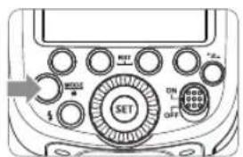
1 Press
2 Turn the Select Dial to choose a desired flash output.
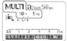
3 Set the flash frequency and flash times.
- Press Function Button 3 < MULT > to select the flash times. Turn the Select Dial to set the number.
- Press Function Button 4
- After you finish the setting, press
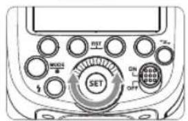
Calculating the Shutter Speed
During stroboscopic flash, the shutter remains open until the firing stops. Use the formula below to calculate the shutter speed and set it with the camera.
Number of Flashes / Flash Frequency = Shutter Speed
For example, if the number of flashes is 10 and the firing frequency is 5 Hz, the shutter speed should be at least 2 seconds.
To avoid overheating and deteriorating the flash head, do not use stroboscopic flash more than 10 times in succession. After 10 times, allow the camera flash to rest for at least 15 minutes. If you try to use the stroboscopic flash more than 10 times in succession, the firing might stop automatically to protect the flash head. If this happens, allow at least 15 minutes' rest for the camera flash.
- Stroboscopic flash is most effective with a highly reflective subject against a dark background.
• Using a tripod and a remote control is recommended.
- A flash output of 1/1 and 1/2 cannot be set for stroboscopic flash.
- Stroboscopic flash can be used with "buLb".
- If the number of flashes is displayed as “—”, the firing will continue until the shutter closes or the battery is exhausted. The number of flashes will be limited as shown by the following table.
Maximum Stroboscopic Flashes:
| Flash Hz output | 1 | 2 | 3 | 4 | 5 | 6-7 | 8-9 | 10 | 11 | 12-14 | 15-19 | 20-50 | 60-200 |
| 1/4 | 7 | 6 | 5 | 4 | 4 | 3 | 3 | 2 | 2 | 2 | 2 | 2 | 2 |
| 1/8 | 14 | 14 | 12 | 10 | 8 | 6 | 5 | 4 | 4 | 4 | 4 | 4 | 4 |
| 1/16 | 30 | 30 | 30 | 20 | 20 | 20 | 10 | 8 | 8 | 8 | 8 | 8 | 8 |
| 1/32 | 60 | 60 | 60 | 50 | 50 | 40 | 30 | 20 | 20 | 20 | 18 | 16 | 12 |
| 1/64 | 90 | 90 | 90 | 80 | 80 | 70 | 60 | 50 | 40 | 40 | 35 | 30 | 20 |
| 1/128 | 100 | 100 | 100 | 100 | 100 | 90 | 80 | 70 | 70 | 60 | 50 | 40 | 40 |
Wireless Flash Shooting: Radio (2.4G) Transmission
- You can set up three slave groups for TTL autoflash shooting. With TTL autoflash, you can easily create various lighting effects.
- Any flash settings for the slave units on the master flash in TTL/Manual/Multi mode will be automatically sent to the slave units. So the only thing you need to do is to set the master unit for each slave group without any operation for the slave units at all during the shooting.
- This flash can work in TTL /M /Multi / OFF flash modes when set as a master unit.
As a slave unit, V860IIIO is compatible with Godox X1 series transmitter e.g. X1T-C(For Canon), X1T-N(For Nikon), X1T-S(For Sony), X1T-F(For Fuji), X1T-O(For Olympus or Panasonic).
• Even with multiple slave units, the master unit can control all of them via wireless.
- In this user manual, "master unit" refers to the camera flash on a camera and "slave unit" will be controlled by the master unit.
1. Wireless Settings
You can switch between normal flash and wireless flash. For normal flash shooting, be sure to set the wireless setting to OFF.
Master Unit Setting
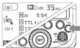
1 Press <*z-> button so that <(φ)> is displayed on the LCD panel. If <(φ) MULTI> is displayed, it means Multi mode is ON.
2 The backlight turns green now.
Slave Unit Setting
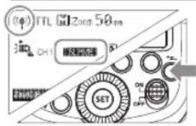
1 Press < +z> button so that < (φ) > and < SLAVE > are displayed on the LCD panel.
2 The backlight turns orange now.
- Setting Master Unit's Flash Mode
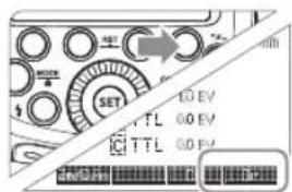
1 Press Function Button 4
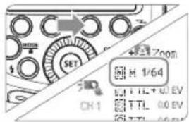
2 Press < MODE > button to switch to Multi mode.
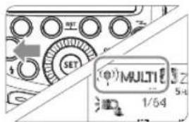
- Setting the Communication Channel
If there are other wireless flash systems nearby, you can change the channel IDs to prevent signal interference. The channel IDs of the master unit and the slave unit(s) must be set to the same.
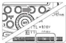
1 Press Function Button 3 < CH > and turn the Select Dial to choose a channel ID from 1 to 32.
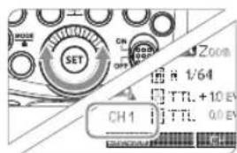
2 Press the
- TTL: Fully Automatic Wireless Flash Shooting
Autoflash Shooting with One Slave Unit
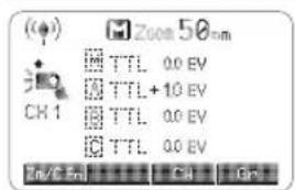
1 Master Unit Setting
- Attach a V860IIO camera flash on the camera and set it as the master unit. (Page 40)
- M/A/B/C can be set as TTL mode independently.
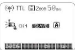
2 Slave Unit Setting
- Set the other camera flash as the wireless slave unit. (Page 41) - The slave unit can be set as A/B/C.
3 Check the communication channel
- If the master unit and slave unit(s) are set to a different channel, set them to the same channel. (Page 41)
4 Position the camera and flashes
- Position the camera and flashes as the picture shows. (Page 44)
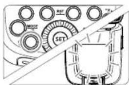
5 Check that the flash is ready
- Check that the master flash ready indicator is lightened. - When the slave flash ready indicator is ready, the AF-assist beam lighting area will blinks at 1 second intervals.
6 Check the flash operation
- Press the master unit's Test Button<>,
- Then, the slave unit will fire. If not, check whether the slave unit is put in the right position or not.
natural_image
Pure mechanical assembly diagram showing gears and a housing without any text or symbols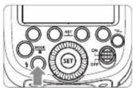
6 Check the flash operation
The slave unit might be out of order or fire an unwanted flash due to the nearby fluorescent lamp or computer screen.
- If the slave unit's auto power off function is workable, press the master unit's test button to power it on. Please note that test firing is unavailable during the camera's regular metering time.
- The effective time of slave auto power off is changeable. (C.Fn-Sv APOT/ Page 48)
- By making some settings, the auto AF-assist transmitter will not blink after the slave unit's flash ready indicator is lightened. (C.Fn-AF/ Page 48)
Using Fully Automatic Wireless Flash
The FEC and other settings that set on the master unit will also be appeared on the slave unit automatically. The slave unit does not need any operation. Use the following settings to make wireless flashes according to the same methods with normal flash shooting.
- Flash Exposure Compensation ( ± / Page 37 )
About Master Unit
Use two or more master units. By preparing several cameras that with master units flash attached, cameras can be changed in shooting while keeping the same lighting source (slave unit).
5. M: Wireless Flash Shooting with Manual Flash
This describes wireless (multiple shooting) using manual flash. You can shoot with a different flash output setting for each slave unit (firing group). Set all parameters on the master unit.
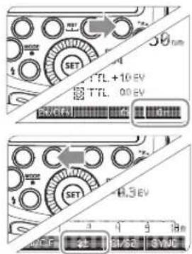
1 Setting the flash mode to
- Press Function Button 4
2 Setting flash output
- When choosing the state of the group, press Function Button 2 < \$+> to set the power output. Turn the Select Dial to set the flash output of the groups. Press the
2 Taking the picture
• Each group fires at the set flash ratio.
6. Multi: Manual Wireless Flash Shooting
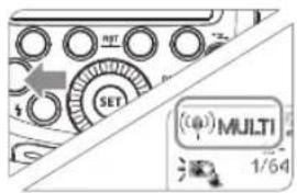
1 Setting stroboscopic flash.
- Press
Using a flash (master/slave) with a radio transmission wireless shooting function make it easy to shoot with advanced wireless multiple flash lighting, in the same way as TTL autoflash shooting. The basic relative position and operation range are as shown in the picture. You can then perform wireless TTL autoflash shooting just by setting the master unit to
Positioning and Operation Range (Example of wireless flash shooting)
• Autoflash Shooting with One Slave Unit
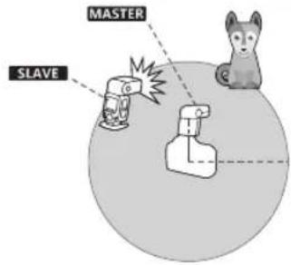
Transmission distance is about 100m.
• Use the supplied mini stand to position the slave unit.
- Before shooting, perform a test flash and test shooting.
- The transmission distance might be shorter depending on the conditions such as positioning of slave units, the surrounding environment and whether conditions.
Wireless Multiple Flash Shooting
You can divide the slave units into two or three groups and perform TTL autoflash while changing the flash ratio (factor). In addition, you can set and shoot with a different flash mode for each firing group, for up to 5 groups.
• Auto Shooting with Two Slave Groups
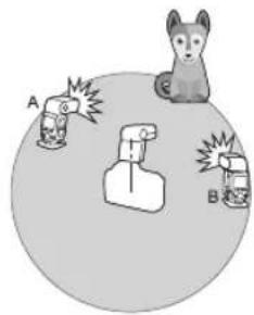
• Auto Shooting with Three Slave Groups
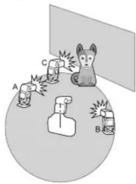
Other Applications
Wireless Control Function
The flash unit is built in with a Wireless Control Port so that you can wirelessly adjust the power level of the flash and the flash triggering.
To control the flash wirelessly, you need a FT-16S remote control set (on-camera and on-flash). Insert its receive end into the Wireless Control Port on the flash and insert the transmit end into the camera hot shoe.
Settings made on the hotshoe-mounted transmit and receive ends will be wirelessly communicated to
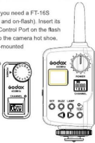
For full instructions on the use of FT series remote control, see its user manual.
Sync Triggering
The Sync Cord Jack is a 2.5mm plug. Insert a trigger plug here and the flash will be fired synchronously with the camera shutter.
Bounce Flash
By pointing the flash head toward a wall or ceiling, the flash will bounce off the surface before illuminating the subject. This can soften shadows behind the subject for a more natural-looking shot. This is called bounce flash.
To set the bounce direction, hold the flash head and turn it to a satisfying angle.
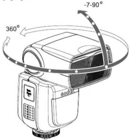
If the wall or ceiling is too far away, the bounced flash might be too weak and result in underexposure.
- The wall or the ceiling should be a plain, white color for high reluctance. If the bounce surface is not white, a color cast may appear in the picture.
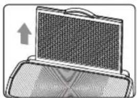
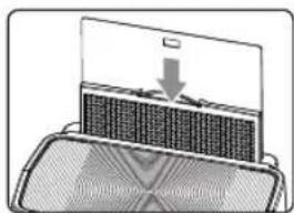
Creating a Catchlight
With the catchlight panel, you can create a catchlight in the subject's eyes to add life to the facial expression.
natural_image
Illustration of a suitcase with a mesh cover and an upward arrow, no text or symbols present1 Point the flash head upward by 90°.
2 Pull out the wide panel. The catchlight panel will come out at the same time.
3 Push the wide panel back in. - Push in only the wide panel. - Follow the same procedures as for bounce flash.
natural_image
Diagram showing a device with a screen and a heat sink, no text or symbols present- Point the flash head straight ahead and then upward by 90°. The catchlight will not appear if you swing the flash head left or right.
- For best catchlight effect, stay 1.5m/4.9ft away from the subject.
ZOOM: Setting the Flash Coverage and Using the Wide Panel
The flash coverage can be set automatically or manually. It can be set to match the lens focal length from 10 mm to 100mm (4/3 system). Also, with the built-in wide panel, the flash coverage can be expanded for 7mm wide-angle lenses.
Choose 4/3 or 135 system in the C.Fn-ZOOM.
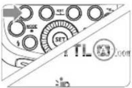
In Manual Zoom mode, press the button.
- Turn the Select Dial to change the flash coverage.
- If <A> is displayed, the flash coverage will be set automatically.
If you set the flash coverage manually, make sure it covers the lens focal length so that the picture will not have a dark periphery.
natural_image
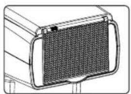
Technical line drawing of a rectangular component with a meshed inner area, no visible text or symbolsUsing the Wide Panel
Pull out the wide panel and place it over the flash head as shown. The flash coverage will then be extended to 7 mm.
- The catchlight panel will come out at the same time. Push the catchlight panel back in.
- The
button will not work.
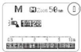
Low Battery Warning
If the battery power is low, <☐> will appear and blink on the LCD panel. Please replace the battery immediately.
C.Fn: Setting Custom Functions
The following table lists the available and unavailable custom functions of this flash.
| C.Fn Custom Functions | |||
| Custom Function Signs | Function | Setting No. | Settings & Description |
| m/ft | Distance indicator | m | m |
| ft | feet | ||
| APO | Auto power off | ON | ON |
| OFF | OFF | ||
| ZOOM | Lens system | 4/3 | 4/3 system |
| 135 | 135 system | ||
| Sv APOT | Slave auto power off timer | 60min | 60min |
| 30min | 30min | ||
| BEEP | Beeper | ON | ON |
| OFF | OFF | ||
| LIGHT | Backlighting time | 12sec | Off in 12 sec. |
| OFF | Always off | ||
| ON | Always lighting | ||
| LCD | LCD contrast ratio | 0~9 | 10 levels |
- Press
Backlight/Custom Setting Button for 2 seconds or longer until C.Fn menu is displayed. The "Ver x.x" in the top-right corner refers to the software version. - Select the Custom Function No.
- Turn the Select Dial to select the Custom Function.
-
Change the Setting.
-
Press
button and the Setting No. blinks. - Turn the Select Dial to set the desired number. Pressing
button will confirm the settings. -
After you set the Custom Function and press
button, the camera will be ready to shoot. -
In the C.Fn states, long press the "Clear" button for 2 seconds until "OK" is displayed on the panel, which means the values in C.Fn can be reset.
Firmware Upgrade
This flash supports firmware upgrade through the USB port. Update information will be released on our official website.
USB connection line is not included in this product. The USB port is a standard Micro USB socket. Common USB connection line is applicable.
Protection Function
1. Over-Temperature Protection
- To avoid overheating and deteriorating the flash head, do not fire more than 30 continuous flashes in fast succession at 1/1 full power. After 30 continuous flashes, allow a rest time of at least 10 minutes.
- If you fire more than 30 continuous flashes and then fire more flashes in short intervals, the inner over-temperature protection function may be activated and make the recycling time over 10 seconds. If this occurs, allow a rest time of about 10 minutes, and the flash unit will then return to normal.
- When the over-temperature protection is started, 🔒 is shown on the LCD display.
Number of flashes that will activate over-temperature protection:
| Power Output Level | Number of Flashes |
| 1/1 | 30 |
| 1/2 +0.7 | 40 |
| 1/2 +0.3 | 50 |
| 1/2 | 60 |
| 1/4(+0.3,+0.7) | 100 |
| 1/8(+0.3,+0.7) | 200 |
| 1/16(+0.3,+0.7) | 300 |
| 1/32(+0.3,+0.7) | 500 |
| 1/64(+0.3,+0.7) | 1000 |
| 1/128(+0.3,+0.7) |
Number of flashes that will activate over-temperature protection in high-speed sync triggering mode:
| Power Output | Times |
| 1/1 | 15 |
| 1/2(+0.3,+0.7); | 20 |
| 1/4(+0.3,+0.7) | 30 |
| 1/8(+0.3,+0.7); | |
| 1/16(+0.3,+0.7) | 40 |
| 1/32(+0.3,+0.7); | |
| 1/64(+0.3,+0.7); | 50 |
| 1/128(+0.3,+0.7); |
2. Other Protections
The system provides real-time protection to secure the device and your safety. The following lists prompts for your reference:
| Prompts on LCD Panel | Meaning |
| E1 | A failure occurs on the recycling system so that the flash cannot fire.Please restart the flash unit. If the problem still exists, please send this product to a maintenance center. |
| E2 | The system gets excessive heat. Please allow a rest time of 10 minutes. |
| E3 | The voltage on two outlets of the flash tube is too high. Please send this product to a maintenance center. |
| E9 | There are some errors occurred during the upgrading process. Please using the correct firmware upgrade method. |
Technical Data
| Model | V860IIQ |
| • Type | |
| Compatible Cameras | Olympus/Panasonic cameras(refer to compatible camera models) |
| Guide No.(1/1 output @ 200mm) | 60 (m ISO 100) |
| 190 (feet ISO 100) | |
| Flash Coverage | 10 to 100mm (4/3 system) or 20 to 200mm (135 system) |
| • Auto zoom (Flash coverage set automatically to match the lens focal length and image size) | |
| • Manual zoom | |
| • Swinging/tilting flash head (bounce flash): 0 to 360° horizontally and -7° to 90° vertically | |
| Flash Duration | 1/300 to 1/20000 seconds |
| • Exposure Control | |
| Exposure control system | TTL autoflash and manual flash |
| Flash exposure compensation (FEC) | Manual. FEB: ±3 stops in 1/3 stop increments(Manual FEC can be combined.) |
| Sync mode | High-speed sync (up to 1/8000 seconds),first-curtain sync, and second-curtain sync |
| Multi flash | Provided (up to 100 times, 200Hz) |
| • Wireless Flash (Optical transmission and 2.4G transmission) | |
| Wireless flash function | Master, Slave, Off |
| Controllable slave groups | 3 (A, B and C) |
| Transmission range (approx.) | ≤100m |
| Channels | 32 (1~32) |
| Slave-ready indicator | Two red indicators blink |
| • Power Supply | |
| Power source | 11.1V/2000mAh Li-ion polymer battery |
| Recycle time | < 1.5 seconds. Red LED indicator will light up when the flash is ready. |
| Full power flashes | Approx. 650 |
| Power saving | Power off automatically after approx. 90 seconds of idle operation. (60 minutes if set as slave) |
| • Sync Triggering Mode | Hotshoe, 2.5mm sync line, Wireless control port |
| • Color Temperature | 5600±200k |
| • Dimensions | |
| W x H x D | 64*76*190 mm |
| Weight without battery | 420g |
| Weight with battery | 540g |
Troubleshooting
If there is a problem, refer to this Troubleshooting Guide.
The Camera Flash cannot be charged.
• The battery is installed in the wrong direction.
→Install the battery in the correct direction.
- The camera flash's internal battery is exhausted.
→If < ☐ > appears and blinks on the LCD panel, replace the battery immediately.
The Camera Flash does not fire.
- The camera flash is not attached securely to the camera.
→Attach the camera's mounting foot securely to the camera. - The electrical contacts of the Camera Flash and camera are dirty.
→Clean the contacts.
The power turns off by itself.
- After 90 seconds of idle operation, auto power off took effect if the flash is set as master.
→Press the shutter button halfway or press any flash button to wake up. - After 60 minutes (or 30 minutes) of idle operation, the flash unit will enter sleep mode if it is set as slave.
→Press any flash button to wake up.
Auto zoom does not work.
- The camera flash is not attached securely to the camera.
→Attach the camera flash's mounting foot to the camera.
The flash exposure is underexposed or overexposed.
- You used high-speed sync.
→With high-speed sync, the effective flash range will be shorter. Make sure the subject is within the effective flash range displayed. - You used Manual Flash mode.
→Set the flash mode to TTL or modify the flash output.
Photos have dark corners or only parts of the target subject are illuminated.
• The focal length of lens exceeds the flash coverage.
→Check the flash coverage you set. This flash unit has the flash coverage between 20 and 200mm, which fits medium-format cameras. Pull the wide panel out to extend the flash coverage.
Compatible Camera Models
This flash unit can be used on the following camera models:
Olympus: E-M10II, E-M5II, E-M1, E-PL8, E-PL7, E-PL6, E-PL5, E-P5, E-P3, PEN-F
Panasonic: DMC-GX85, DMC-G7, DMC-GF1, DMC-LX100, DMC-G85, DMC-GH4, DMC-FZ2500GK
- This table only lists the tested camera models, not all Olympus/Panasonic cameras. For the compatibility of other camera models, a self-test is recommended.
- Rights to modify this table are retained.
Maintenance
- Shut down the device immediately should abnormal operation be detected.
- Avoid sudden impacts and the product should be dedusted regularly.
- It is normal for the flash tube to be warm when in use. Avoid continuous flashes if unnecessary.
- Maintenance of the flash must be performed by our authorized maintenance department which can provide original accessories.
- This product, except consumables e.g. flash tube, is supported with a one-year warranty.
- Unauthorized service will void the warranty.
- If the product had failures or was wetted, do not use it until it is repaired by professionals.
- Changes made to the specifications or designs may not be reflected in this manual.
FCC Warning
Any Changes or modifications not expressly approved by the party responsible for compliance could void the user's authority to operate the equipment. This device complies with part 15 of the FCC Rules. Operation is subject to the following two conditions: (1) This device may not cause harmful interference, and (2) this device must accept any interference received, including interference that may cause undesired operation.
FCC Radiation Exposure Statement:
This equipment complies with FCC radiation exposure limits set forth for an uncontrolled environment. This transmitter must not be co-located or operating in conjunction with any other antenna or transmitter.


- TTL锂电机顶闪光灯
- V860II ID
- 神牛摄影器材有限公司
- 在使用本产品之前:
- Foreword
- Thank you for purchasing this product.
- For Your Safety
- Conventions used in this Manual
- Contents
- Name of Parts
- - Body
- - Control Panel
- - LCD Panel
- • What's in the Box of V860IIO Kit?
- - What's in the Box of V860IIIO (only flash unit)?
- • Separately Sold Accessories
- Battery
- - Features
- - Cautions
- - Loading and Unloading the Battery
- - Battery Level Indication
- Attaching to a Camera
- Power Management
- Flash Mode: TTL Autoflash
- TTL Mode
- FEC: Flash Exposure Compensation
- High-Speed Sync
- Second-Curtain Sync
- Flash Mode -- M: Manual Flash
- Flash Output Range
- Optical S1 Secondary Unit Setting
- Optical S2 Secondary Unit Setting
- Flash Mode -- Multi:Stroboscopic Flash
- Calculating the Shutter Speed
- Number of Flashes / Flash Frequency = Shutter Speed
- Wireless Flash Shooting: Radio (2.4G) Transmission
- Wireless Settings
- Master Unit Setting
- Using Fully Automatic Wireless Flash
- About Master Unit
- M: Wireless Flash Shooting with Manual Flash
- Setting the flash mode to
- Setting flash output
- Taking the picture
- Multi: Manual Wireless Flash Shooting
- Setting stroboscopic flash.
- Positioning and Operation Range (Example of wireless flash shooting)
- Wireless Multiple Flash Shooting
- Other Applications
- Wireless Control Function
- Sync Triggering
- Bounce Flash
- Creating a Catchlight
- ZOOM: Setting the Flash Coverage and Using the Wide Panel
- In Manual Zoom mode, press the button.
- Using the Wide Panel
- Low Battery Warning
- C.Fn: Setting Custom Functions
- Firmware Upgrade
- Protection Function
- Over-Temperature Protection
- Other Protections
- Troubleshooting
- The Camera Flash cannot be charged.
- The Camera Flash does not fire.
- The power turns off by itself.
- Auto zoom does not work.
- The flash exposure is underexposed or overexposed.
- Photos have dark corners or only parts of the target subject are illuminated.
- Compatible Camera Models
- Maintenance
- FCC Warning
- FCC Radiation Exposure Statement:
Marke : GODOX
Modell : V860IIO
Kategorie : Blitz