CV503 - Kamera Marshall Electronics - Kostenlose Bedienungsanleitung
Finden Sie kostenlos die Bedienungsanleitung des Geräts CV503 Marshall Electronics als PDF.


Benutzerfragen zu CV503 Marshall Electronics
0 Frage zu diesem Gerät. Beantworten Sie die, die Sie kennen, oder stellen Sie Ihre eigene.
Eine neue Frage zu diesem Gerät stellen
Laden Sie die Anleitung für Ihr Kamera kostenlos im PDF-Format! Finden Sie Ihr Handbuch CV503 - Marshall Electronics und nehmen Sie Ihr elektronisches Gerät wieder in die Hand. Auf dieser Seite sind alle Dokumente veröffentlicht, die für die Verwendung Ihres Geräts notwendig sind. CV503 von der Marke Marshall Electronics.
BEDIENUNGSANLEITUNG CV503 Marshall Electronics
Marshall
Broadcast A/V Division
natural_image
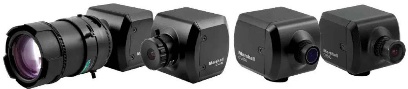
Four black Marshall CVD50 cameras with lens and control knobs, shown from different angles (no text or symbols visible on body)CV503, CV506, CV344, CV346
Compact & Miniature Full-HD Cameras
User Manual
Table of Contents
Table of Contents 01
-
General Information 02
-
Menu Structure 03
-
OSD Joystick and Button 05
-
WB Control 06
-
AE Control 07
-
Day / Night 08
-
Audio 09
-
Image Control 10
-
Special 11
-
Setup 12
-
Reset 13
-
Exit 14
-
Troubleshooting 15
Warranty END
1. General Information
Thank you for your purchase of a Marshall Miniature or Compact Camera.
The Marshall Camera team recommends thoroughly reading this guide for a deep understanding of on-screen-display (OSD) menus, breakout cable operation, settings adjustment explanation, troubleshooting, and other critical information.
Please carefully remove all contents of box, which should include the following components:
CV503/CV506 includes:
• Camera with 3.6mm lens (interchangeable)
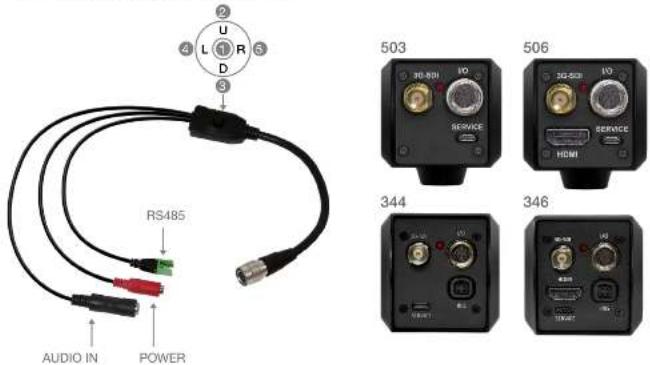
• Camera Breakout Cable (Power/RS485/Audio)
• 12V Power Supply
CV344/CV346 includes:
- Camera with CS/C mount (lens sold separately)
• Camera Breakout Cable (Power/RS485/Audio)
• C-Mount Lens Adapter (only used when using C-Mount lens)
• 12V Power Supply
The CV503/506 ships with a 3.6mm (72°AOV) M12 lens installed and is interchangeable to any number of Marshall M12 lenses.
The CV344/346 Camera utilizes a CS/C lens mount and does not include a stock CS/C Lens. CS/C mount lenses are sold separately, as well as adapters to other lens mount types.
Each camera comes set to default at 1920x1080p @ 30fps out of the box; which can be changed in the OSD Menu to a variety of resolutions and framerates.
If the camera is accidentally changed to a resolution or framerate that your monitor or equipment doesn't accept, please follow the instructions below to reset camera to factory default:
- Plug the camera into power source and connect breakout cable to rear camera panel (locking connection). Power LED should illuminate.
- Push OSD joystick button UP, DOWN, UP, DOWN and PUSH and HOLD for five seconds.
- Camera should reset to 1920x1080p @ 30fps.
-
If camera does not reset, repeat steps after a power-cycle.
-
Menu Structure
| SETUP SUB MENU | SUB MENU | |
| WB CONTROL | ATW | |
| ONE PUSH | ||
| INDOOR | ||
| OUTDOOR | ||
| MANUAL | BLUE | |
| RED | ||
| AE CONTROL | AUTO | AGC MAX |
| SENS UP | ||
| AE BRIGHT | ||
| FLK CONTROL | ||
| LENS MODE (DC IRIS ONLY) | ||
| SHUT FIX | SHUTTER | |
| AGC MAX | ||
| SENS UP | ||
| AE BRIGHT | ||
| FLK CONTROL | ||
| AGC FIX | AGC | |
| AE BRIGHT | ||
| FLK CONTROL | ||
| LENS MODE (DC IRIS ONLY) | ||
| MANUAL | SHUTTER | |
| IRIS | ||
| AGC | ||
| FLK CONTROL | ||
| LENS MODE (DC IRIS ONLY) | ||
| DAY / NIGHT | DAY | |
| NIGHT NIGHT COLOR | ||
| AUDIO | MIC/LINE | |
| AUDIO LEVEL | ||
| MIC ATTENUATOR | ||
Marshall
| SETUP SUB MENU $UB MENU | ||
| AUDIO | SAMPLE BITS | |
| IMAGE CONTROL | LENS SHADING | |
| CONTRAST | ||
| BRIGHTNESS | ||
| SATURATION | ||
| HUE | ||
| EDGE ENHANCE | ||
| AUTO SATURATE | ||
| AUTO EDGE | ||
| BLACK WHITE LEVEL | ||
| GAMMA CORRECT | ||
| DNR | DNR MODE | |
| DNR LEVEL | ||
| SPECIAL | DZOOM | |
| DEFOG | ||
| DIS | ||
| BACKLIGHT | ||
| BINNING | ||
| DEFECT PIXEL | ||
| DISP FUNCTION | ||
| WDR | ||
| FLICKER DETECT | ||
| PRIVACY | ||
| SETUP | CAM TITLE | |
| COMMUNICATION RS-485/ID | ||
| SYSTEM INFO | ||
| OUTPUT FORMAT | ||
| RESET USER/FACTORY | ||
| EXIT | ||
www.marshall-usa.com3 4
- OSD Joystick and Button
text_image
U L R S D RS485 AUDIO IN POWER 503 30-501 SERVICE 506 30-502 SERVICE HDMI 344 346I/O Cable (included in box) for CV503, CV506, CV344, CV346
- SET Used to access the menu and confirm selection.
- UP Used to move the cursor up.
- DOWN Used to move the cursor down.
- LEFT Used to move the cursor left and change the value
- RIGHT Used to move the cursor to the right and change the value.
Press SET button to access the Main Menu
| MENU | ||
| WB CONTROL | > | |
| AE CONTROL | > | |
| DAY/NIGHT | > | |
| AUDIO | > | |
| IMAGE CONTROL | > | |
| SPECIAL | > | |
| SETUP | > | |
| RESET | > | |
| EXIT | ||
Icon indicates "Press OSD button" or "Enter Sub Menu"
Marshall
4. WB CONTROL
Select WB CONTROL using the UP or DOWN button. You can change between AUTO, ATW, PUSH, and MANUAL using the LEFT or RIGHT buttons.
- ATW: Continuously adjusts camera color balance in accordance with any change in color temperature. Compensates for color temperature changes within the range of 1,900°K to 11,000°K.
- ONE PUSH: Color temperature will be manually adjusted by pushing the OSD button. Place the white paper in front of the camera when OSD button is pressed to obtain optimum result.
• MANUAL: Select this to fine-tune White Balance manually.
You can adjust the blue and red tone level manually. - BLUE: Adjust the Blue tone of the image. (0\~100)
- RED: Adjust the Red tone of the image. (0-100)
• INDOOR: Select this to adjust white balance to indoor lighting condition. - OUTDOOR: Select this to adjust white balance to outdoor lighting condition.
| MENU | |
| WB CONTROL | > |
| AE CONTROL | > |
| DAY/NIGHT | > |
| AUDIO | > |
| IMAGE CONTROL | > |
| SPECIAL | > |
| SETUP | > |
| RESET | > |
| EXIT | |
- Adjust White Balance first by using the ATW mode before switching to MANUAL mode.
- White Balance may not work properly under the following conditions. In this case, select the ATW mode.
- When the ambient illumination of the subject is dim.
- If the camera is directed towards a fluorescent light or is installed in place where illumination changes dramatically, the White Balance operation may become unstable.
5. AE CONTROL
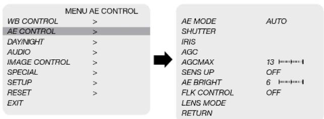
Select AE CONTROL using the UP or DOWN button. You can select one sub-mode using the UP or DOWN buttons.
text_image
MENU AE CONTROL WB CONTROL > AE MODE AUTO AE CONTROL > SHUTTER DAY/NIGHT > IRIS AUDIO > AGC IMAGE CONTROL > AGCMAX 13 SPECIAL > SENS UP OFF SETUP > AE BRIGHT 6 RESET > FLK CONTROL OFF EXIT LENS MODE RETURN- AUTO: Adjusts the exposure level automatically. Detailed fine tuning options are available under this menu.
- SHUT FIX: Provides more detailed shutter speed options. All other controls are tuned for the selected shutter speed.
-
AGC FIX: Provides more detailed gain option. All other controls are tuned for the selected gain value.
• MANUAL: Adjusts the exposure level manually -
SHUTTER: Speed can be set at auto or manual. (1/30-1/10,000)
- IRIS SPEED: Electronic Iris speed can be controlled, for DC Iris lens only. (0\~5)
- AGC: Electronic Iris speed can be controlled, for DC Iris lens only. (0\~5)
- AGC MAX: Used to set maximum gain value to control the video noise caused by Auto Gain Control. (Off, Low, Middle, High, DMIN, DMID, DMAX)
- SENS UP: Controls the digital slow shutter to allow extra light into the camera and adjust the picture quality. (Off, x2-x10)
- AE BRIGHT: Select this to adjust auto exposure brightness levels. (0–10)
- LENS MODE: Lens setting will be optimized for selected environment, for DC Iris lens only.
- FLK CONTROL: Provides a proper image sensor frequency to match the power frequency in order to minimize video flicker.
6. DAY / NIGHT
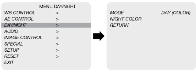
Select DAY / NIGHT using the UP or DOWN button. You can select one sub-mode from AUTO, COLOR, and NIGHT using the UP or DOWN buttons.
MODE: Set camera to either color mode or B&W mode. (Day, Night)
DAY: When set to DAY mode, camera stays in color and IR cut filter is engaged.
NIGHT: When set to NIGHT mode, camera stays in B&W and IR cut filter is removed.
- NIGHT COLOR: When on, camera stays on color mode. Night (B&W) can be selected from this mode. (On, Off)
flowchart
graph LR
    A["MENU DAY/NIGHT"] --> B["MODE"]
    A --> C["NIGHT COLOR"]
    A --> D["RETURN"]
    E["WB CONTROL"] --> F[">"]
    G["AE CONTROL"] --> H[">"]
    I["DAY/NIGHT"] --> J[">"]
    K["AUDIO"] --> L[">"]
    M["IMAGE CONTROL"] --> N[">"]
    O["SPECIAL"] --> P[">"]
    Q["SETUP"] --> R[">"]
    S["RESET"] --> T[">"]
    U["EXIT"] --> V[">"]
7. AUDIO
Select AUDIO using the UP or DOWN button and enter ON using SEL button. You can select one sub-mode using the UP or DOWN buttons.
- MIC / LINE: Select MIC or LINE for the audio input source.
• AUDIO LEVEL: Select this to adjust audio levels manually. -
MIC ATTENUATOR: Audio attenuation can be controlled from this menu to minimize the audio noise level
-
SAMPLE BITS: Select the bit depth of audio
| MENU AUDIO | |
| WB CONTROL | > MODE OFF |
| AE CONTROL | > AUDIO LEVEL 0 dB |
| DAY/NIGHT | > MIC AT TENUATOR OFF |
| AUDIO | > AGC LIMIT |
| IMAGE CONTROL | > SAMPLE BITS 24 BITS |
| SPECIAL | > RETURN |
| SETUP | > |
| RESET | > |
| EXIT | |
8. IMAGE CONTROL
Select IMAGE CONTROL using the UP or DOWN button.
You can select LENS SHADING, CONTRAST, HUE, And EDGE ENHANCE using the UP or DOWN buttons.
| MENU IMAGE CONTROL | |
| WB CONTROL | > |
| AE CONTROL | > |
| DAY/NGHT | > |
| AUDIO | > |
| IMAGE CONTROL | > |
| SPECIAL | > |
| SETUP | > |
| RESET | > |
| EXIT | |
- LENS SHADING: Corrects inconsistent brightness level in the image.
- CONTRAST: Adjust the image contrast level.
• BRIGHTNESS: Adjust the image brightness level.
• SATURATION: Adjust the image saturation level.
• HUE: Adjust the image hue level.
• EDGE ENHANCE: Adjust the image sharpness level. - AUTO SATURATE: Decrease saturation automatically when noise scene is detected.
• AUTO EDGE: Adjust line sharpness level automatically. - BLACK WHITE LEVEL: Adjust the image black level value.
• GAMMA CORRECT: Adjust the image output gamma level. - DNR: Reduces video noise at low ambient light.
Select the DNR level from OFF, LOW, MIDDLE, and HIGH using the LEFT or RIGHT button.
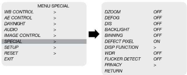
9. SPECIAL
Select SPECIAL using the UP or DOWN button.
You can select DEFOG, MOTION DETECT, BACKLIGHT, DEFECT PIXEL, and FLICKER DETECT using the UP or DOWN buttons.
flowchart
graph LR
    A["MENU SPECIAL"] --> B["DB"]
    A --> C["DEFOG"]
    A --> D["DIS"]
    A --> E["BACKLIGHT"]
    A --> F["BINNING"]
    A --> G["DEFECT PIXEL"]
    A --> H["DISP FUNCTION"]
    A --> I["WDR"]
    A --> J["FLICKER DETECT"]
    A --> K["PRIVACY"]
    A --> L["RETURN"]
• DZOOM: Digitally zoom the video by the desired ratio.
- DEFOG: This feature will help increase visibility in extreme weather conditions, such as fog, rain or in a very strong luminous intensity.
• DIS: This feature enables digital image stabilization
- BACKLIGHT: Adjust backlight compensation by choosing either BLC HLM from this menu.
• BINNING: Enable or disable pixel binning.
- DEFECT PIXEL: Advanced defective pixel correction menu.
- DISP FUNCTION: Display effect such as freeze mirror, rotation, and style can be applied from this menu.
- WDR: This feature enables user to view both object and background more clearly when background is too bright.
- FLICKER DETECT: Adjust the image sensor frequency to match the power frequency.
- PRIVACY: Mask an area you want to hide on the screen by applying the privacy zones.
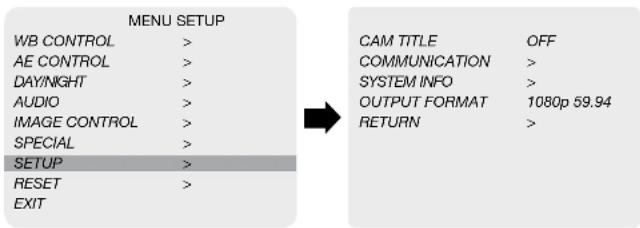
10. SETUP
CAMERA setup can be adjusted from this menu.
You can select CAMERA ID, Communication, System Info, and Output Format using the UP or DOWN buttons.
text_image
MENU SETUP WB CONTROL > AE CONTROL > DAY/NIGHT > AUDIO > IMAGE CONTROL > SPECIAL > SETUP > RESET > EXIT CAM TITLE OFF COMMUNICATION > SYSTEM INFO > OUTPUT FORMAT 1080p 59.94 RETURN >• CAM TITLE: Camera title can be turned ON or OFF.
• COMMUNICATION: VISCA communication can be adjusted.
1. CAM ID: Camera ID can be setup. (0\~7)
2. ID DISPLAY: Camera ID display can be displayed.
3. BAUDRATE : Camera baudrate can be set.
(2400, 4800, 9600, 19200, 38400)
- SYSTEM INFO: Camera information can be found under this menu.
- OUTPUT FORMAT: Camera resolution and frame rate can be set. (1080 by default)
Select the FRAME RATE using the LEFT or RIGHT buttons.
Available Frame Rates are:
1920 x 1080p 60, 59.94, 50, 30, 29.97, 25, 24, 23
1920 x 1080/60, 59.94, 50
1280 x 720p 60, 59.94, 50
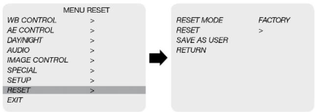
11. RESET
Select RESET using the UP or DOWN buttons.
- RESET: Reset the camera settings the factory defaults or user setting value.
flowchart
graph LR
    A["MENU RESET"] --> B["RESET MODE"]
    A --> C["RESET"]
    A --> D["SAVE AS USER"]
    A --> E["RETURN"]
    B --> F["FACTORY"]
    C --> G[">"]
    D --> H[">"]
    E --> I[">"]
    J["WB CONTROL"] --> K[">"]
    L["AE CONTROL"] --> M[">"]
    N["DAY/NIGHT"] --> O[">"]
    P["AUDIO"] --> Q[">"]
    R["IMAGE CONTROL"] --> S[">"]
    T["SPECIAL"] --> U[">"]
    V["SETUP"] --> W[">"]
    X["RESET"] --> Y[">"]
    Z["EXIT"] --> AA[">"]
- ON: Set the camera setting to either "FACTORY" or "USER" of "CHANGE" menu. Make sure to select the right mode from "CHANGE" before defaulting the camera.
- RESET MODE: Select the desired setting mode.
Select from USER or FACTORY using the LEFT or RIGHT button.
- USER: Select "USER" if setting value user saved last is needed.
- FACTORY: Select "FACTORY" if factory default setting is needed.
"FRAME RATE", "CAM ID", and "BAUDRATE" will note change.
12. EXIT
Select EXIT using the UP or DOWN button.
| MENU | |
| WB CONTROL | > |
| AE CONTROL | > |
| DAY/NGHT | > |
| AUDIO | > |
| IMAGE CONTROL | > |
| SPECIAL | > |
| SETUP | > |
| RESET | > |
| EXIT | |
- SAVE: Exit the setup after saving the value changes.
Marshall
13. TROUBLESHOOTING
Before sending the camera for repair, please check below to make sure that the camera is installed correctly. If it still does not perform adequately, please consult with your supplier.
| Problem Solutions | |
| Nothing appears on the screen. | a. Check that all connected devices are powered on.b. Confirm that the voltage is correct.c. Confirm that the power supply provides enough current to power the camera.d. Check that all video cables are correctly connected. |
| The picture is not clear. | a. Check that your monitor is correctly adjusted.b. Confirm that the glass in front of the lens is clean. If there is dust, dirt, or fingerprints on the glass, the image quality will be affected.To clean the glass, use a soft, dry, and non-abrasive cloth or a commercially available lens cleaning set.c. Correctly adjust the focus. |
| The picture has interference. | a. The camera may be close to a high voltage source, such as a power generator.b. The BNC cable is not terminated properly.c. The video cables are not connected properly. |
| The picture is flickering continually. | a. Check the termination and set the impedance at 750 properly.b. Ensure that the camera is not pointing towards the Sun or any light source.c. Check if there is any intermediate device.d. Check if the distance of the video cable exceeds the maximum transferable limitation. |
| The camera is not synchronizing with the reference signal. | a. Make sure Tri-Level reference signal is used.b. Locking takes up to 1 minute depending on the signal strength.Make sure the sync LED is solidly lit.c. Check if the cable and connectors used in reference sync are in good condition.d. Make sure the cable length used in reference sync does not exceed 100 ft.e. Make sure OUTPUT EN is on when using the genlock output. |
Warranty
Marshall Electronics warranties to the first consumer that this device will, under normal use, be free from defects in workmanship and materials, when received in its original container, for a period of two years from the purchase date. This warranty is extended to the first consumer only, and proof of purchase is necessary to honor the warranty. If there is no proof of purchase provided with a warranty claim, Marshall Electronics reserves the right not to honor the warranty set forth above. Therefore, labor and parts may be charged to the consumer. This warranty does not apply to the product exterior or cosmetics. Misuse, abnormal handling, alterations or modifications in design or construction void this warranty. No sales personnel of the seller or any other person is authorized to make any warranties other than those described above, or to extend the duration of any warranties on behalf of Marshall Electronics, beyond the time period described above.
Due to constant effort to improve products and product features, specifications may change without notice.
Marshall
20608 Madrona Avenue, Torrance, CA 90503
Tel: (800) 800-6608 / (310) 333-0606 • Fax: 310-333-0688
www.marshall-usa.com
support@marshall-usa.com