Light Storm LS C300d II - Beleuchtung Aputure - Kostenlose Bedienungsanleitung
Finden Sie kostenlos die Bedienungsanleitung des Geräts Light Storm LS C300d II Aputure als PDF.


Benutzerfragen zu Light Storm LS C300d II Aputure
0 Frage zu diesem Gerät. Beantworten Sie die, die Sie kennen, oder stellen Sie Ihre eigene.
Eine neue Frage zu diesem Gerät stellen
Laden Sie die Anleitung für Ihr Beleuchtung kostenlos im PDF-Format! Finden Sie Ihr Handbuch Light Storm LS C300d II - Aputure und nehmen Sie Ihr elektronisches Gerät wieder in die Hand. Auf dieser Seite sind alle Dokumente veröffentlicht, die für die Verwendung Ihres Geräts notwendig sind. Light Storm LS C300d II von der Marke Aputure.
BEDIENUNGSANLEITUNG Light Storm LS C300d II Aputure
Aputure®
Light Storm
LS C300d II
Product Manual
English
Foreword
Thank you for purchasing Aputure "Light Storm" LS C300d II
The Aputure LS C300d II is a complete redesign of the original C300d. We've taken all of your favorite features of the C300d and loaded it with upgrades, improvements and new features.
IMPORTANT SAFETY INSTRUCTIONS
When using this unit, basic safety precautions should always be followed, including the following:
- Read and understand all instructions before using.
- Close supervision is necessary when any fixture is used by or near children. Do not leave the fixture unattended while in use.
- Care must be taken as burns can occur from touching hot surfaces.
- Do not operate the fixture if a cord is damaged or if the fixture has been dropped or damaged - until it has been examined by qualified service personnel.
- Position any power cables such that they will not be tripped over, pulled, or put into contact with hot surfaces.
- If an extension cord is necessary, a cord with an amperage rating at least equal to that of the fixture should be used. Cords rated for less amperage than the fixture may overheat.
-
Always unplug the lighting fixture from the electrical outlet before cleaning and servicing, or when not in use. Never yank the cord to remove the plug from the outlet.
-
Let the lighting fixture cool completely before storing.
-
To reduce the risk of electric shock, do not immerse this fixture in water or any other liquids.
-
To reduce the risk of fire or electric shock, do not disassemble this fixture. Contact Aputure Customer Service or take it to qualified service personnel when service or repair work is required. Incorrect reassembly may cause electric shock when the lighting fixture is in use.
-
The use of an accessory attachment not recommended by the manufacturer may increase the risk of fire, electric shock, or injury to any persons operating the fixture.
-
Power this fixture by connecting it to a grounded outlet.
-
Please remove the protective cover before powering on the light.
-
Please remove the black inner EVA protection before using the reflector.
-
Please do not block the ventilation and do not look at the light directly when it is powered on.
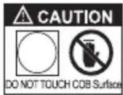
text_image
CAUTION DO NOT TOUCH COB Surface-
Please do not place the LED lighting fixture near any liquids or other flammable objects.
-
Only use a dry microfiber cloth to clean the product.
18 Please have the product checked by authorized service personnel agent if your product has a problem.
-
The malfunctions caused by unauthorized disassemble are not covered under the warranty.
-
We recommend only using the original Aputure cable accessories. Please note that our warranty for this product does not apply to any repairs required due to
any malfunctions of unauthorized accessories, although you may request such repairs for a fee.
-
This product is certified by RoHS, CE, KC, PSE, and FCC. Please operate the product in full compliance with the operation standards. Please note that this warranty does not apply to repairs arising from malfunctions, although you may request such repairs on a chargeable basis.
-
The instructions and information in this manual are based on thorough, controlled company testing procedures. Further notice will not be given if the design or specifications change.
SAVE THESE INSTRUCTIONS
FCC Compliance Statement
This device complies with Part 15 of the FCC Rules. Operation is subject to the following two conditions:
(1) This device may not cause harmful interference. (2) This device must accept any interference received, including interference that may cause undesired operation.
Warning: Changes or modifications not expressly approved by the party responsible for compliance could void the user's authority to operate the equipment.
NOTE: This equipment has been tested and found to comply with the limits for a Class B digital device, pursuant to Part 15 of the FCC Rules. These limits are designed to provide reasonable protection against harmful interference in a residential installation. This equipment generates uses and can radiate radio frequency energy and, if not installed and used in accordance with the instructions, may cause harmful interference to radio communications. However, there is no guarantee that interference will not occur in a particular installation. If this equipment does cause harmful interference to radio or television reception, which can be determined by turning the equipment off and on, the user is encouraged to try Reorient or relocate the receiving antenna.
- Increase the separation between the equipment and receiver.
- Connect the equipment into an outlet on a circuit different from that to which the receiver is connected.
- Consult the dealer or an experienced radio/TV technician for help.
RF Warning Statement:
This device has been evaluated to meet general RF exposure requirements.
Check list
When you unbox the product, please make sure all the items listed below are included. Otherwise, please contact the seller immediately.
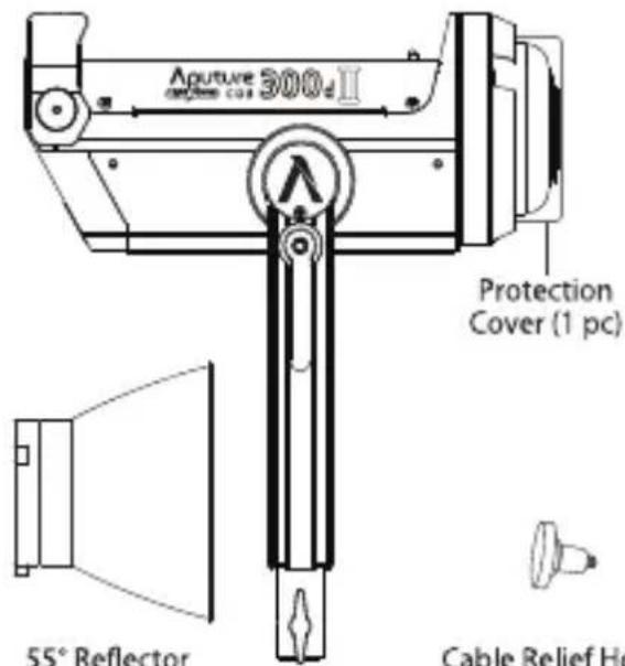
text_image
Aputure 300Ω Protection Cover (1 pc) 55° Reflector Cable Relief Ho(1 pc) 300d II Lamp Head (1 pc)
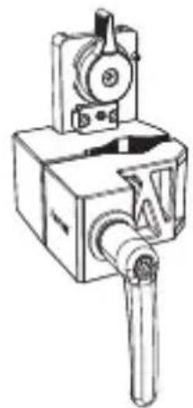
natural_image
Technical line drawing of a mechanical device with no visible text or symbolsCable Relief Hook (1 pc)
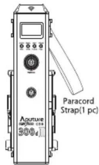
text_image
Paracord Strap(1 pc) Aputure 300dQuick-Release Clamp (1 pc)
Control Box (1 pc)
text_image
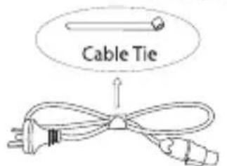
Cable TieNeutrik ^+ powerCON Cable (1 pc)
text_image
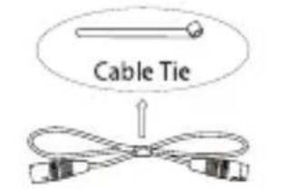
Cable Tie5-Pin Male-to-Female XLR (1 pc)
natural_image
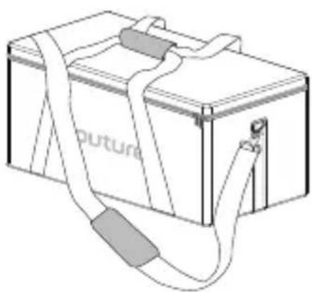
Line drawing of a battery pack with coiled cable and label 'puture' (no other text or symbols)300d II Carrying Case (1 pc)
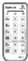
VA-Remote RC1+
(1 pc)

CR2032 Button Cell Battery (1 pc)
Product Details
1. Light
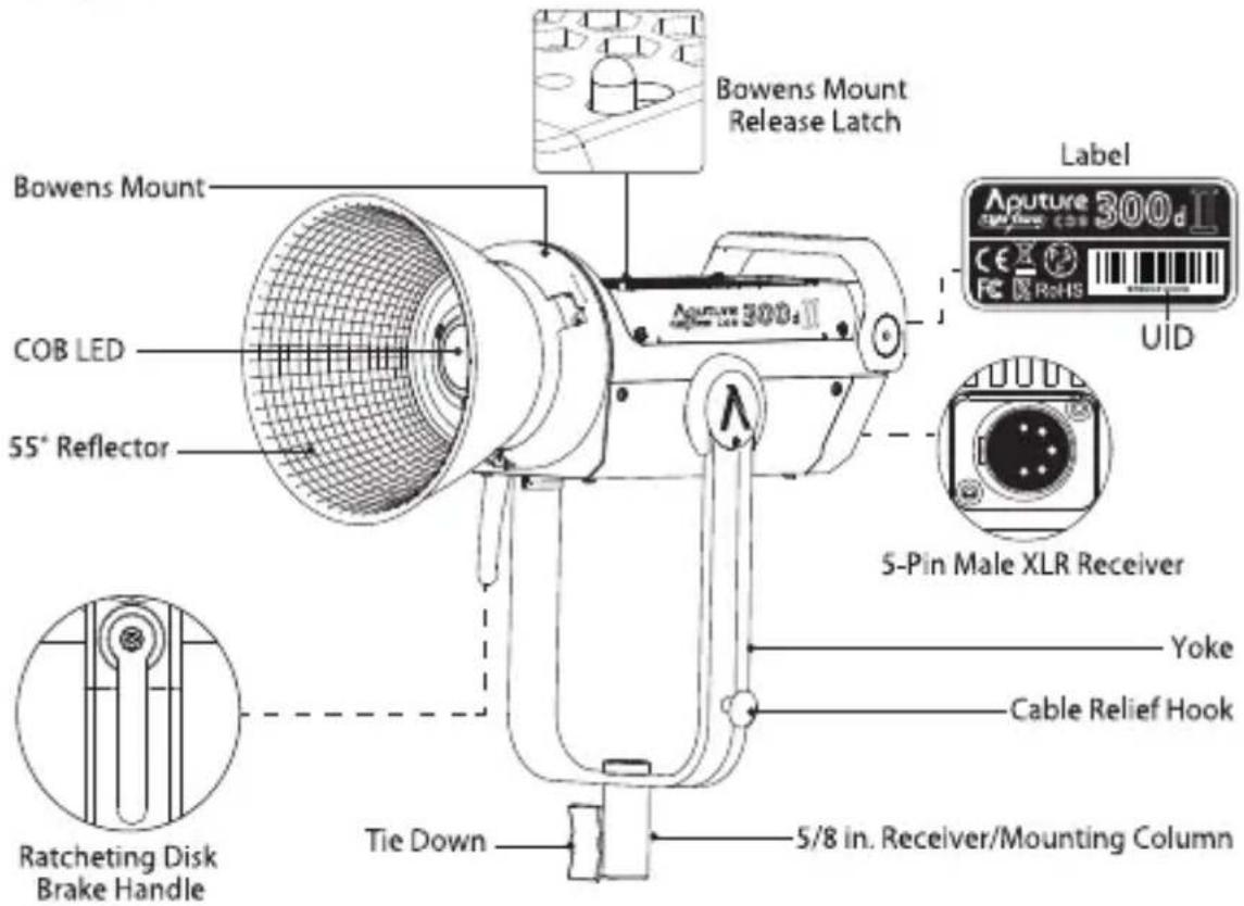
text_image
Bowens Mount Release Latch Label Aputure 300d II COB LED 55° Reflector 5-Pin Male XLR Receiver Yoke Cable Relief Hook Ratcheting Disk Brake Handle Tie Down 5/8 in. Receiver/Mounting Column2. Controller box
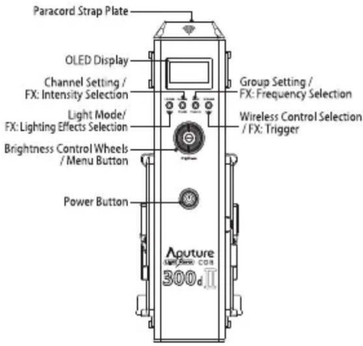
text_image
Paracord Strap Plate OLED Display Channel Setting / FX: Intensity Selection Light Mode/ FX: Lighting Effects Selection Brightness Control Wheels / Menu Button Power Button Group Setting / FX: Frequency Selection Wireless Control Selection / FX: Trigger Aputure 300d.Ⅱ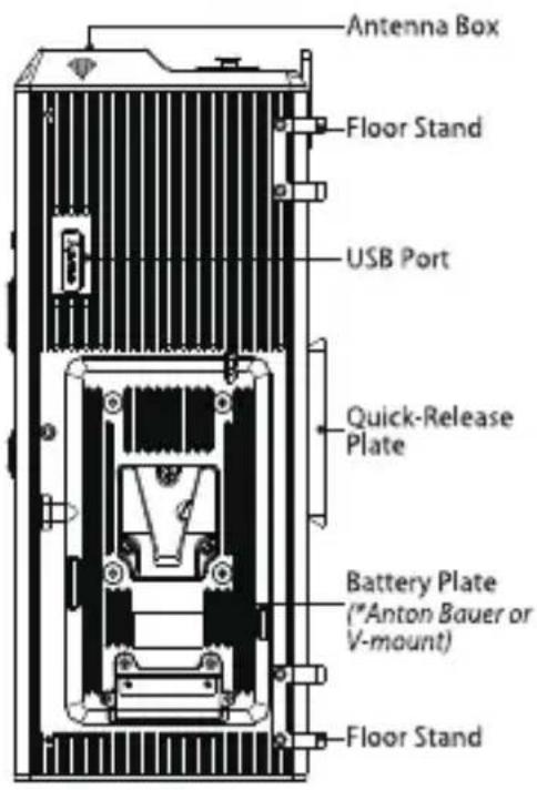
text_image
Antenna Box Floor Stand USB Port Quick-Release Plate Battery Plate (*Anton Bauer or V-mount) Floor Stand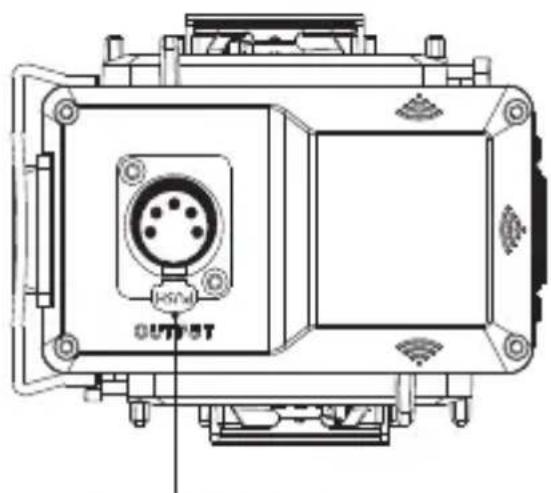
natural_image
Technical line drawing of a mechanical device with labeled ports and components (no readable text or symbols)5-Pin Female XLR Power Output
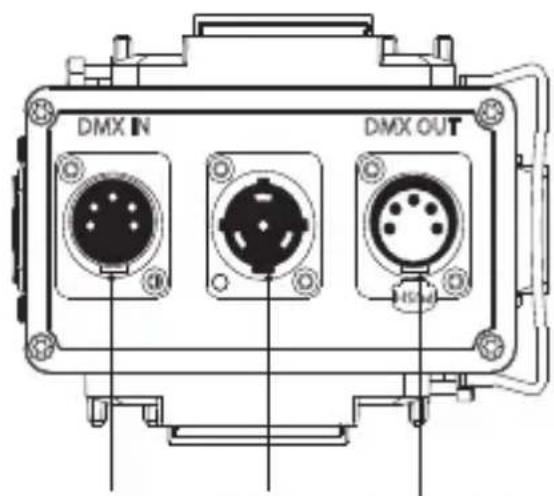
text_image
DMX IN DMX OUTDMX IN Port
NEUTRIK
DMX OUT Port
powerCON
Power Input
3. VA-Remote RC1+
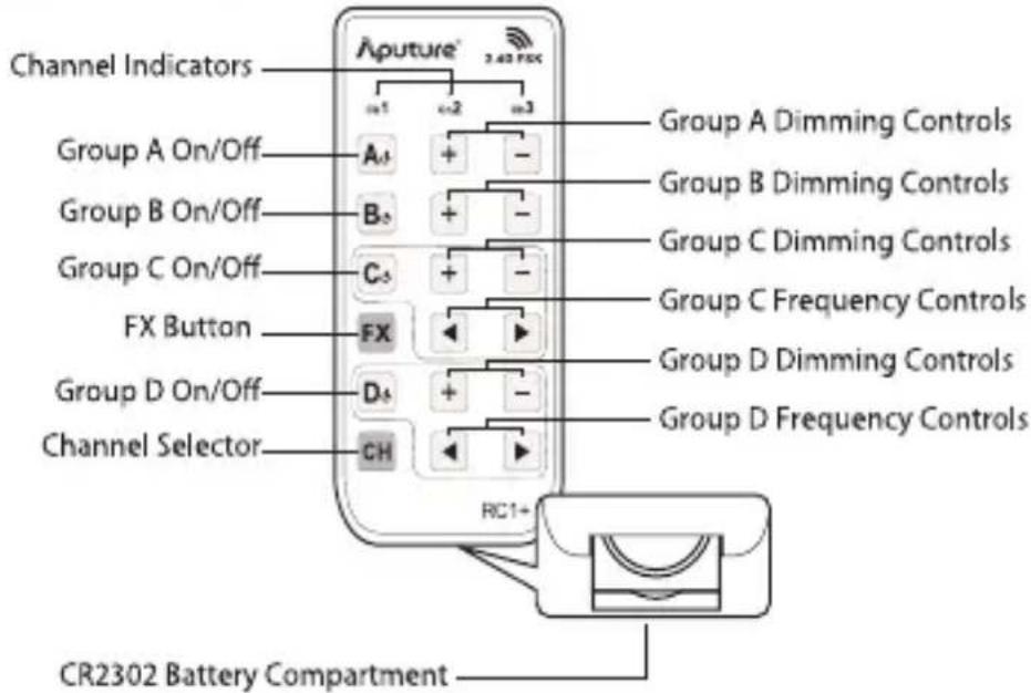
text_image
Channel Indicators Aputure® 3.42 PCS Group A On/Off A1 + - Group B On/Off B2 + - Group C On/Off C3 + - Group C Dimming Controls Group C Dimming Controls Group C Frequency Controls FX Button FX Group D Dimming Controls D4 + - Group D Frequency Controls Channel Selector CH RC1+ CR2302 Battery CompartmentInstallations
- Installing the cable relief hook
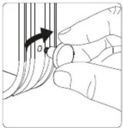
natural_image
Illustration of a hand turning a curved object with an arrow indicating rotation (no text or symbols)2. Attaching/detaching the protection cover
Pull back the retaining pin, rotate the cover clockwise, then detach the cover. To reattach the cover, insert it into the Bowens mount and rotate counterclockwise.
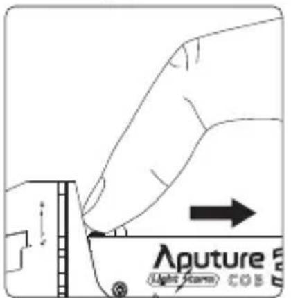
text_image
Aputure Light Scene COS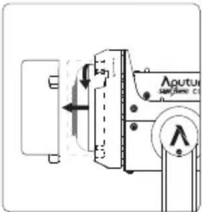
text_image
Technical diagram showing a mechanical device with labeled components and directional arrows indicating movement or force.Notice: Always remove the protection cover prior to turning on the light. Always re-install the cover when packing it away.
3. Attaching/detaching the reflector
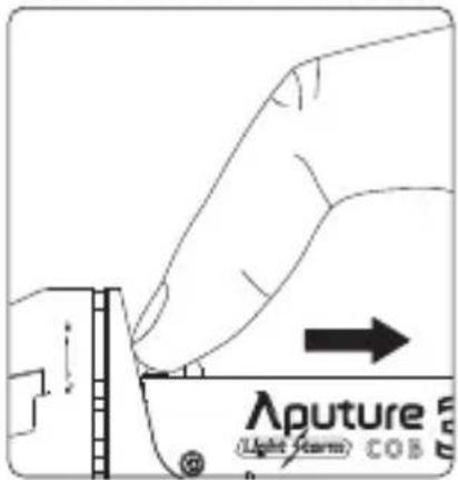
To install the reflector, pull back the retaining pin, insert the reflector into the Bowens mount, and rotate it counterclockwise as shown in the following pictures. To remove the reflector, pull back the retaining pin and rotate the reflector clockwise.
text_image
Aputure (Light Forms) COB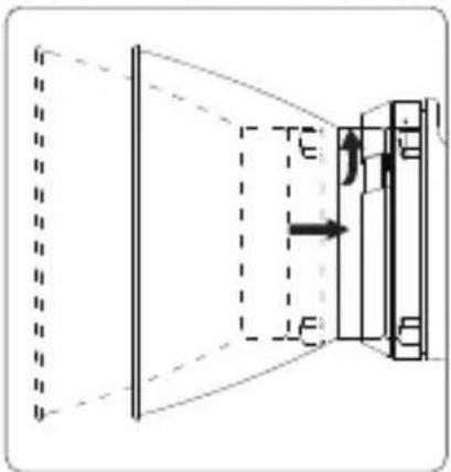
text_image
Diagram illustrating light refraction through a grating with labeled incident and refracted rays, showing incident and refracted states.4. Setting up the Light
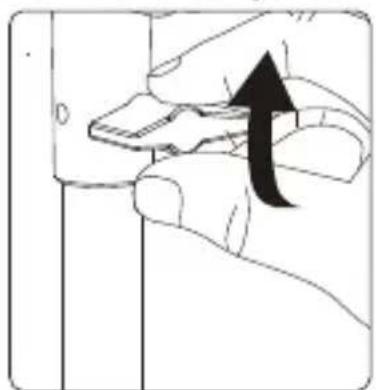
Mount the light onto a light stand, then fix it in place using the tie-down screw on the 5/8 inch receiver/mounting column. Then loosen/tighten the handbrake locking mechanism on the yoke to adjust the tilt of the fixture.
natural_image
Illustration of a hand holding a smartphone with an upward arrow indicating action (no text or symbols present)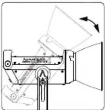
text_image
Technical diagram of a mechanical device with labeled components and directional arrows indicating motion or flow.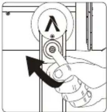
text_image
Diagram showing a hand holding a valve with an arrow indicating clockwise motion, labeled with symbols like 'A' and a plus sign.5. Instructions for Quick-Release Clamp
1) Clamp the Quick-Release Clamp onto a light stand.
2) To attach the control box, rotate the release lever to unlock the quick-release baseplate, then mount the control box onto the Quick-Release Clamp (the release lever will automatically spring back).
3) To remove the control box, grasp it firmly, then unlock the quick-release plate by turning the release lever, and detach the control box.
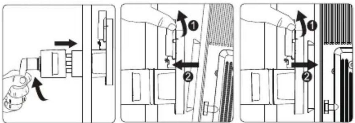
text_image
Technical diagram showing three-step assembly steps of a device with labeled components and directional arrows indicating movement.Specifications
| Weight | 670g / 1.48lbs | Sizes (L*W*H) | 10.35x8.74x12.5cm / 4.07x3.44x4.92in |
| * The Quick-Release Clamp can clamp onto square or round pipe with a diameter between 2-5cm or 0.79-1.97in. | |||
6. Connect the light to the control box
Connect the light to the control box using the 5-Pin Male-to-Female XLR cable as shown below.
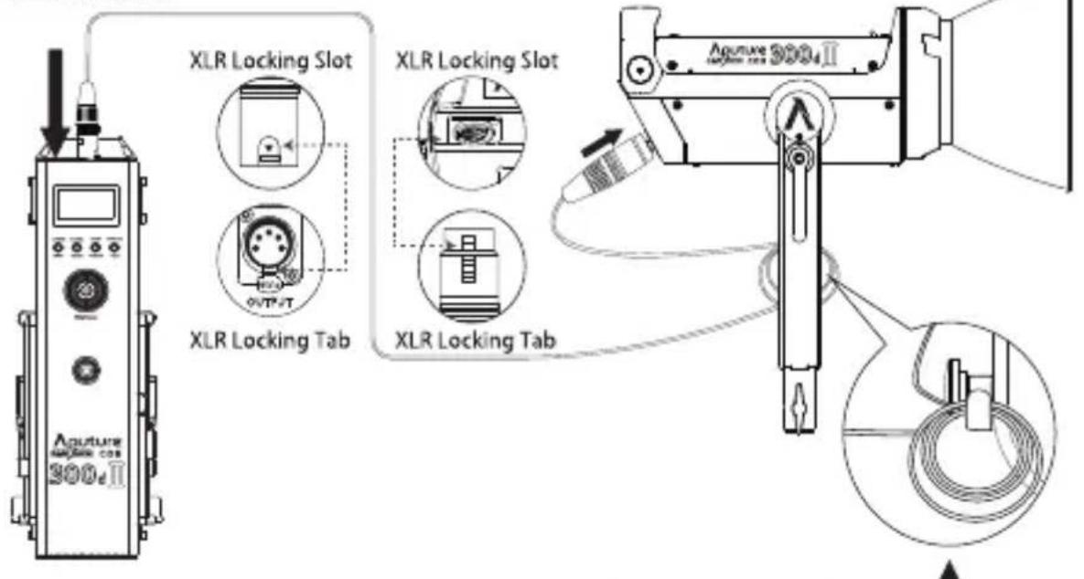
text_image
XLR Locking Slot XLR Locking Tab XLR Locking Slot XLR Locking Tab Aperature 300d II 300d II* Hang the cable from the head cable relief hook to manage and reduce tension on the cable.
* Disconnect the XLR head cable by pushing down on the locking tabs on the female XLR connectors, then removing the cable.
7. Powering up the controller
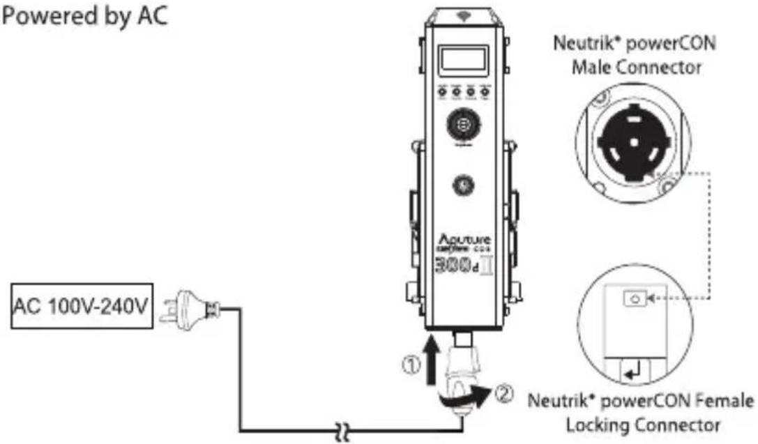
1) Powered by AC
text_image
Powered by AC AC 100V-240V Aouture 300d ① ② Neutrik* powerCON Male Connector Neutrik* powerCON Female Locking ConnectorTo disconnect the Neutrik® powerCon cable, pull back on the yellow release tab on the cable connector, and rotate the connector counterclockwise.
2) Powered by the battery
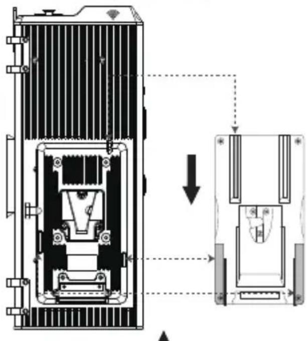
text_image
Technical diagram showing internal components of a device with an arrow indicating transformation or assembly process.V-Mount Battery
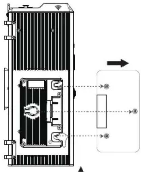
text_image
Technical diagram of a battery internal structure with labeled components and directional arrows indicating flow or movement.Anton Bauer Battery
* Batteries: Voltage 12-16.8V; Recommended ≥15A continuous discharge.
* The 300d II can be operated using a single battery for up to half of the fixture's maximum output. Plugging the light into AC power or using two batteries allows you to utilize the light's full output. When powering the light from a single battery, you must install the battery on the right side of the control box, or it will not turn on.
* Do not use non-14.4v batteries (batteries with voltages outside of the 12-16.8V range). Using higher voltage batteries will damage the power supply and the lighting fixture.
* Only use batteries that support the necessary continuous current discharge specifications mentioned above. If non-compatible batteries are used, the batteries will enter a protection state and the lighting fixture will not operate as intended.
* Customers can choose V-Mount or A-Mount battery plates for their control boxes upon purchase according to their needs.
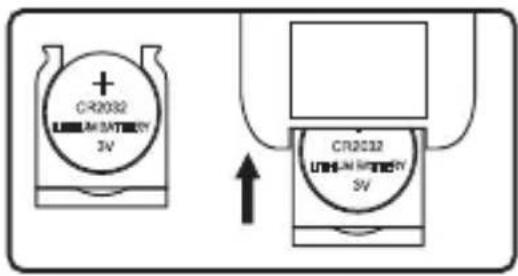
8. Insert the button battery to power VA-Remote RC1+
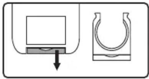
natural_image
Diagram showing a container being inserted into a U-shaped container with a curved handle, indicating fluid or material movement (no text or symbols)Remove battery compartment
text_image
CR2032 UHM-AM BATTERY 3V CR2032 UHM-AM BATTERY 3VInstall button battery and insert it into the VA-Remote RC1+
Operations
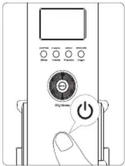
1. Press the power button to turn the light on and off
text_image
Diagram of a device control panel with labeled buttons and a power button icon* Default: Channel 1, Group A
text_image
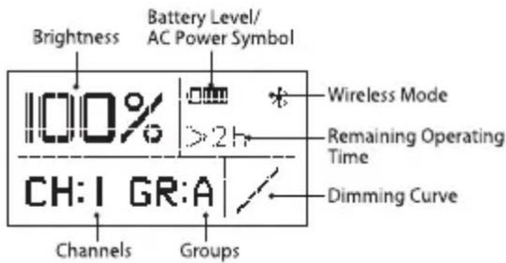
Brightness Battery Level/ AC Power Symbol 100% Wireless Mode 2 h Remaining Operating Time CH: I GR:A Dimming Curve Channels Groups2. Manual Control
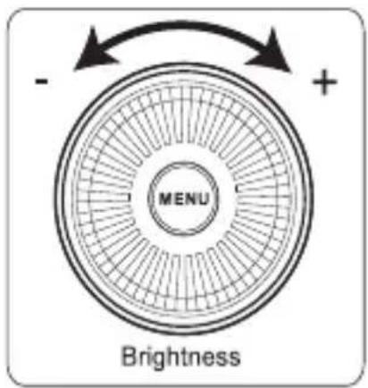
1) Rotate the wheel to adjust the brightness from 0-100%
text_image
- + MENU Brightness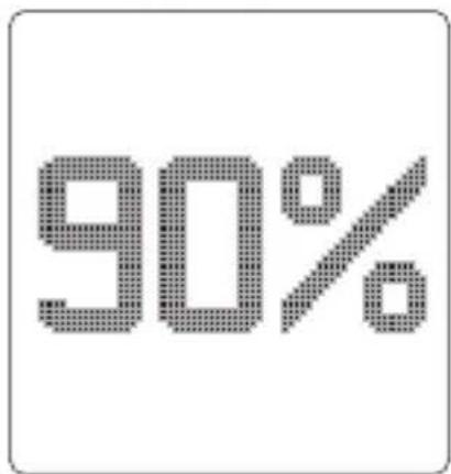
text_image
90%2) Lighting FX Mode
Press and hold the Effects button for 2 seconds to activate Lighting FX mode, then short press the Effects button to toggle between Paparazzi, Fireworks, Fault bulb, Lightning, TV, Pulsing, Strobe and Explosion, etc.
a. Paparazzi Mode
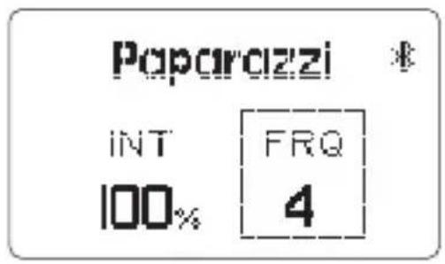
text_image
Paparazzi INT FRQ 100% 4b. Fireworks Mode
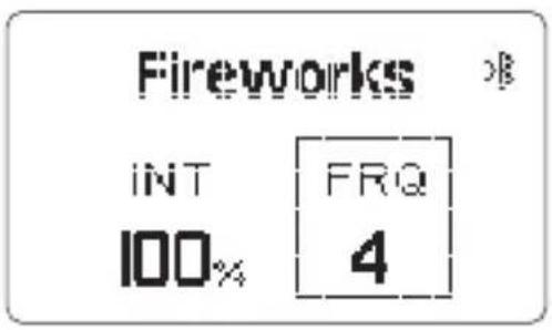
text_image
Fireworks INT FRQ 100% 4c. Fault bulb Mode
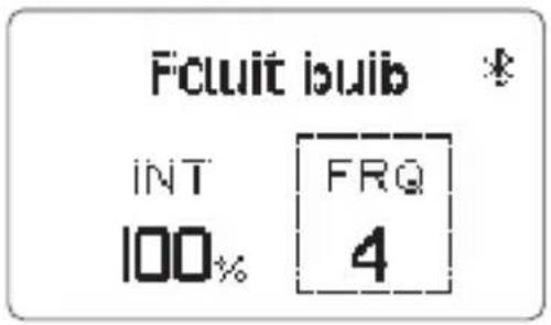
text_image
Fcluit ibuib INT FRQ 100% 4d. Lightning Mode
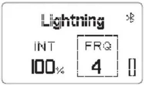
text_image
Lightning INT FRQ 100% 4 []* In lightning mode, short press the Trigger button to single trigger the light effect, long press the Trigger button to enter the cycle mode.
e. TV Mode
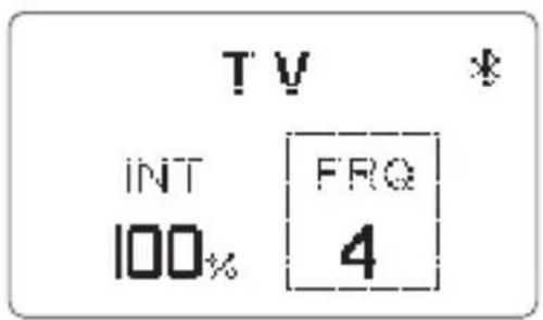
text_image
TV * INT FRQ 100% 4f. Pulsing Mode

text_image
Pulsing INT 100% FRQ 4g. Strobe Mode
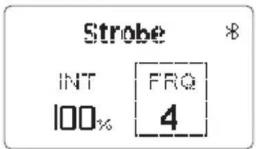
text_image
Strobe INT FRQ 100% 4h. Explosion Mode
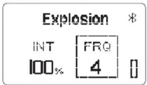
text_image
Explosion INT FRQ 100% 4 []* In explosion mode, short press the Trigger button to single trigger the light effect.
When in Lighting FX mode, short press the "Intensity" button to enter Intensity Adjustment Mode. Then rotate the brightness dimming wheel to adjust the intensity from 10% to 100% as displayed on the screen.
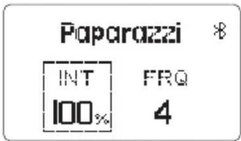
text_image
Paparazzi * INT FRQ 100% 4When in Lighting FX menu, short press the "Frequency" button to enter Frequency Adjustment Mode. Then rotate the brightness dimming wheel to adjust the frequency of the effect from 1 to 10 and R (Random) as displayed on the screen.
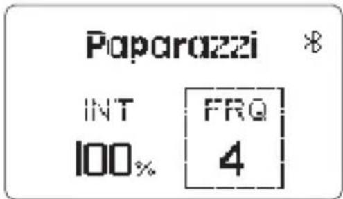
text_image
Paparazzi * INT FRQ 100% 4* If the light is powered off, upon turning on again, the light resumes its last saved setting.
3) Wireless Connectivity Modes
Press the Wireless/Trigger button in order to switch between 2.4GHz Wireless Remote Control, Bluetooth SIG Mesh Sidus Link App Control, and no wireless control.
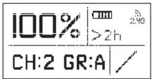
text_image
100% >2h CH:2 GR:A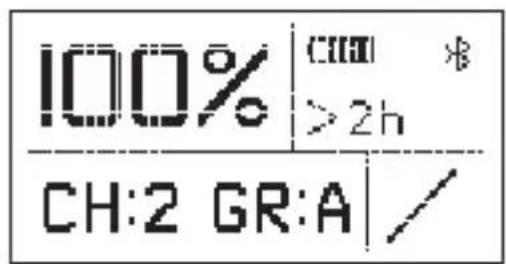
text_image
100% | >2h CH:2 GR:A /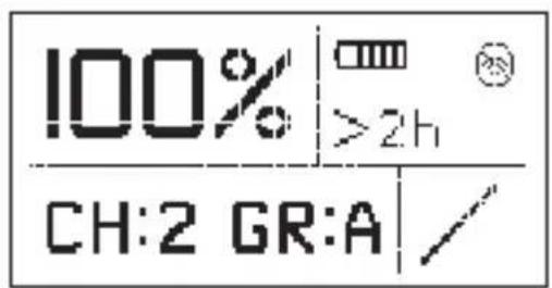
text_image
100% | >2h CH:2 GR:A /* When setting up the device with the Bluetooth mobile application, the corresponding name of the fixture is LS C300d II ***** (six digits + letters are fixture serial numbers).
4) Press the MENU button to enter the system menu interface, as shown below.
| DimX ModeDimming CurveFan ModeStudio Mode | BT ResetLanguageUSB ModeExit |
5) DMX mode
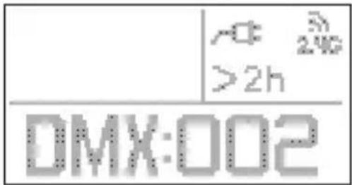
Press the MENU button to enter the system menu, rotate the dimming wheel to select DMX mode and press the MENU button again to enter DMX mode.
text_image
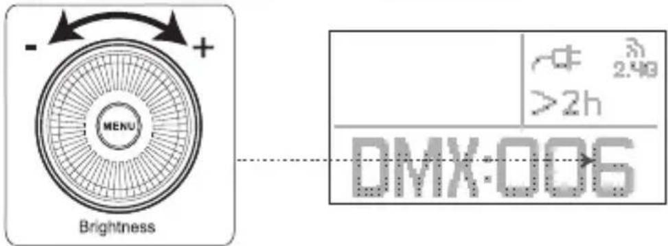
A 240 >2h DMX:002When in DMX mode, rotate the brightness control wheels to set the device's DMX channel. Then press the MENU button again to save your selection.
text_image
- + - MENU Brightness -Φ 2.40 >2h DMX:0066) Dimming curve mode
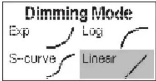
Press the MENU button to enter the system menu, rotate the dimming wheel to select Dimming Curve, and press the MENU button again to enter the dimming curve selection menu. Using the wheel to choose from exponential (Exp), logarithmic (Log), S-Curve, or linear dimming curves, and press the MENU button to make your selection.
text_image
Dimming Mode Exp Log S-curve Linear7) Fan mode
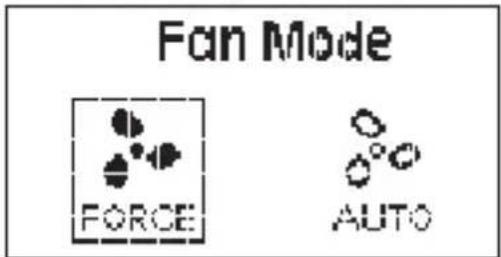
Press the MENU button to enter the system menu, rotate the dimming wheel to select Fan Mode, and press the MENU button again to enter Fan Mode. Use the wheel to select between Force and Auto, then press the MENU button to confirm your selection.
text_image
Fan Mode FORCE AUTO* In "Force Mode" the fan will continuously spin at its maximum speed. In "Auto Mode" the fan will only begin spinning when the light has reached 45 °C.
8) Studio mode
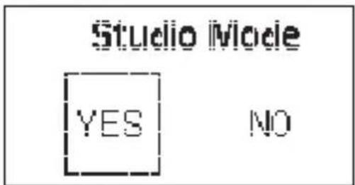
Press the MENU button to enter the system menu, rotate the dimming wheel to select Studio Mode, and press the MENU button again to enter the Studio Mode menu. Once in the menu, use the wheel to choose between "YES" or "NO" and press the MENU button to confirm your selection.
text_image
Studio Mode YES NO* When Studio Mode is active, the light will turn on as soon as it receives power, without having to press the power button.
* Studio Mode is active as the factory default.
9) Bluetooth reset
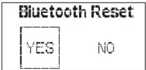
(1) Press the MENU button to enter the system menu, rotate the dimming wheel to select BT Reset. Press the MENU button again to enter the Bluetooth Menu. Use the wheel to select "YES" to reset the Bluetooth pairing (the pop-up window displays the current reset progress and is completed within 5 seconds); or select "NO" to return to the previous menu.
text_image
Bluetooth Reset YES NO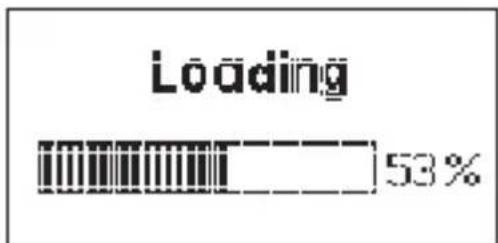
text_image
Loading 53%(2) After resetting the light's Bluetooth connection, your mobile phone or tablet will be able to connect to and control the light.
(3) If the Bluetooth Reset fails, a [Reset Failed] screen will pop-up, and the light will return to Bluetooth mode after 2 seconds.
* The Bluetooth reset function must be performed when the light is in Bluetooth wireless connectivity mode.
* The light must be connected to your mobile device using the Sidus Link mobile application, and not via your device's typical Bluetooth connection menu.
10) Language
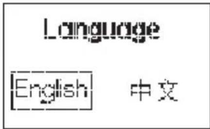
Press the MENU button to enter the system menu, rotate the dimming wheel to select Language, and press the MENU button again to enter the Language menu. Use the wheel to select from the available languages. Initial languages include "English" and "Chinese".
text_image
Language English 中文* The factory default language is English.
* Enter the language selection interface and select "English" or "中文".
11) USB Mode
(1) The control box has a built-in USB port for firmware updates (for both the control box and lamp head).
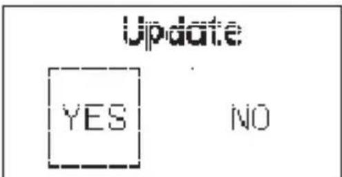
(2) To update the light's firmware, press the MENU button to enter the system menu, rotate the dimming wheel to select USB Mode, and press the MENU button again to enter the Update menu. Use the wheel to select "YES" or "NO". If a USB flash drive containing a firmware update is mounted in the USB port, the screen will display an upgrade progress bar.
(3) If a USB flash drive is not inserted into the USB port of the flash drive does not contain a firmware upgrade file, entering the Update menu and choosing "YES" will return you to the system menu interface.
text_image
Update YES NO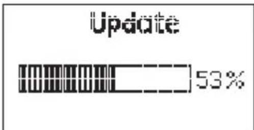
text_image
Update 53%* Only FAT16 and FAT32 storage formats can be used for firmware updates. Incompatible formats will result in the screen displaying a format error and will return to the main menu.
* DO NOT unplug the light or the USB flash drive during the update process. In the case of an unexpected power failure, DO NOT remove the USB flash drive. When the power is restored, the fixture will automatically resume the update process. After successfully updating the firmware, the fixture will automatically restart.
3. Remote Control
You can control the LS C300d II from any channel or group configuration.
* Light Storm lights have three channels (1/2/3) and four groups (A/B/C/D).
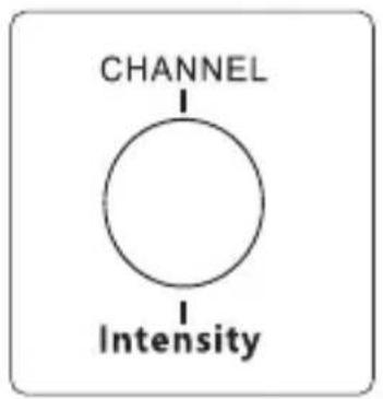
1) Configuring channel and group settings on the control box Press the CHANNEL button to toggle between channels 1, 2, & 3.
flowchart
graph TD
    A["CHANNEL"] --> B["Intensity"]

text_image
CH:2Press the GROUP button to toggle between groups A, B, C, & D.
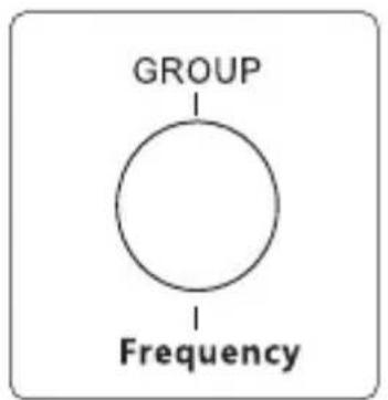
flowchart
graph TD
    A["GROUP"] --> B["Frequency"]
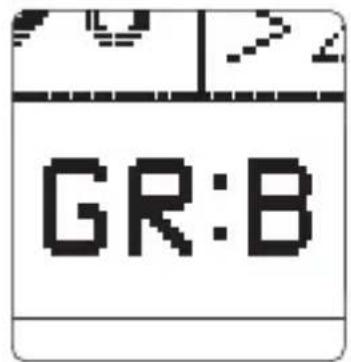
text_image
GR:B2) Configuring channel setting on the remote
text_image
CH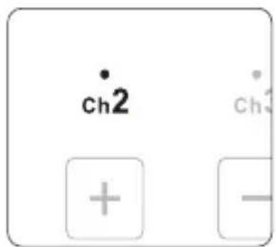
text_image
ch2 ch3 + -▲ Press the CH button to toggle between channels 1, 2, and 3)
"ch2" indicator lights
3) Adjusting brightness
Press A/B/C/D to toggle the lights on or off, press ( + / - ) to adjust the brightness of the light from 0 to 100% accordingly.
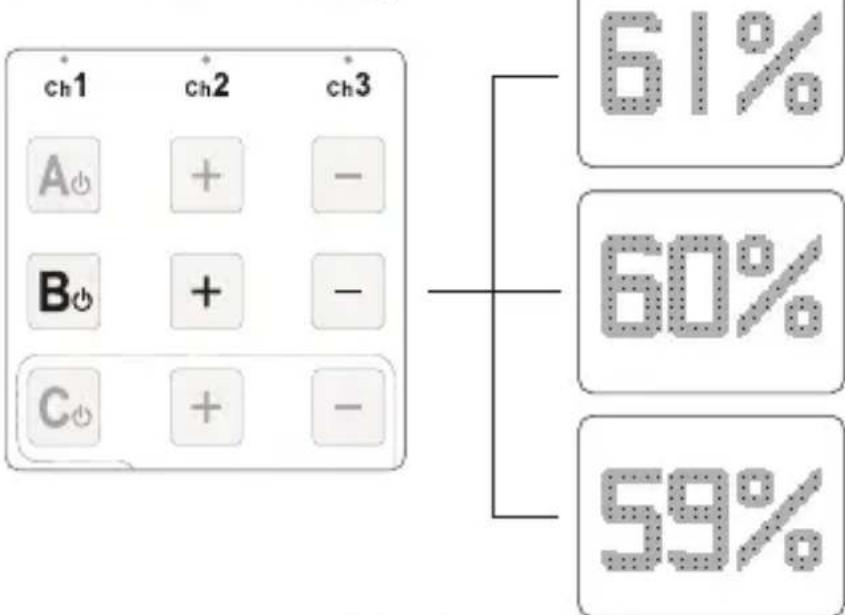
other
| Category | Value (%) | |---|---| | A | 61 | | B | 60 | | C | 59 |* This remote will not work in either DMX or DMX FX Modes.
* The remote control will only operate the light if the light is in 2.4Ghz wireless connectivity mode.
4) FX Control
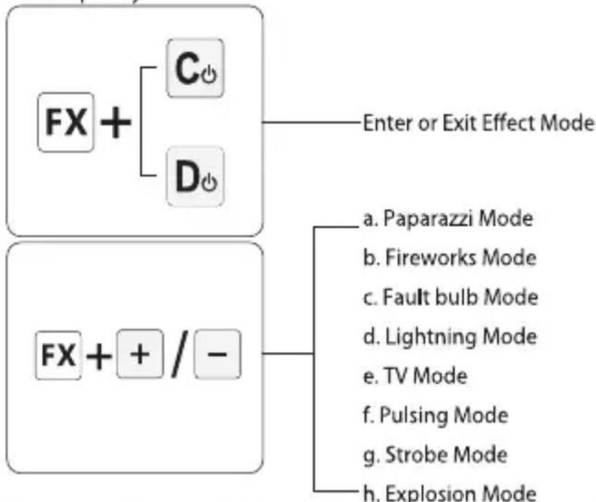
Press the (FX + C_4 / D_6) button to enter or exit lighting effect mode. Press the (FX + + / -) to toggle between different effects.
Press the( + / - ) buttons to adjust the output of the light. Press the( ◀ / ▶ ) buttons to toggle the effect frequency.
flowchart
graph TD
    A["FX +"] --> B["C"]
    A --> C["D"]
    B --> D["Enter or Exit Effect Mode"]
    C --> D
    E["FX + + / -"] --> F["a. Paparazzi Mode"]
    E --> G["b. Fireworks Mode"]
    E --> H["c. Fault bulb Mode"]
    E --> I["d. Lightning Mode"]
    E --> J["e. TV Mode"]
    E --> K["f. Pulsing Mode"]
    E --> L["g. Strobe Mode"]
    E --> M["h. Explosion Mode"]
* Only "FX"+ "C and D" can be used to control lighting effects, while groups "A and B" can only be used for normal brightness adjustments turning lights on and off.
4. DMX control
1) Connect a standard DMX controller
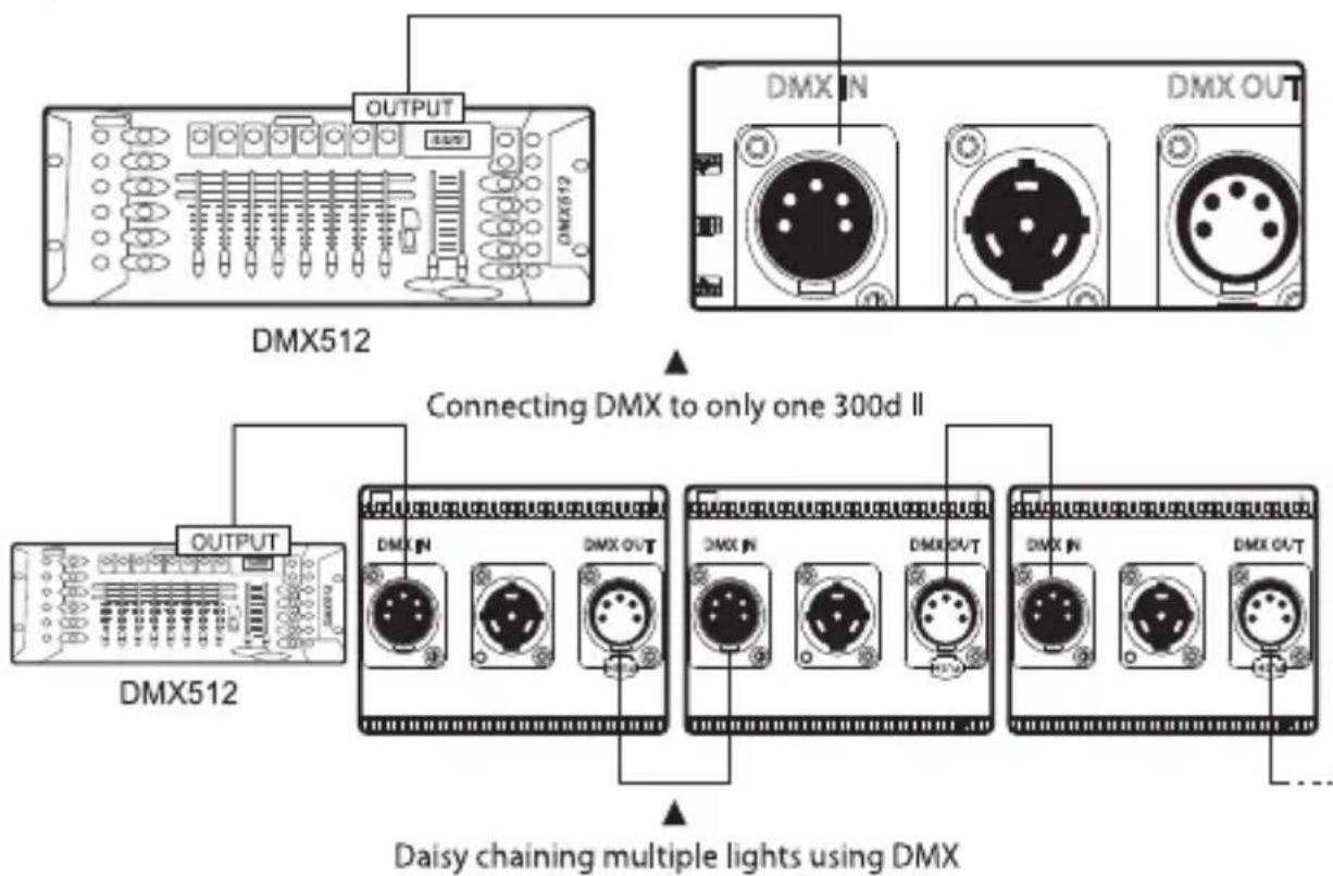
flowchart
graph TD
    A["DMX512"] --> B["OUTPUT"]
    A --> C["DMX N"]
    A --> D["DMX OUT"]
    E["DMX512"] --> F["OUTPUT"]
    E --> G["DMX N"]
    E --> H["DMX OUT"]
    I["Daisy chaining multiple lights using DMX"] --> J["DMX N"]
    I --> K["DMX OUT"]
* See the DMX interface definition as seen in the pictures below:
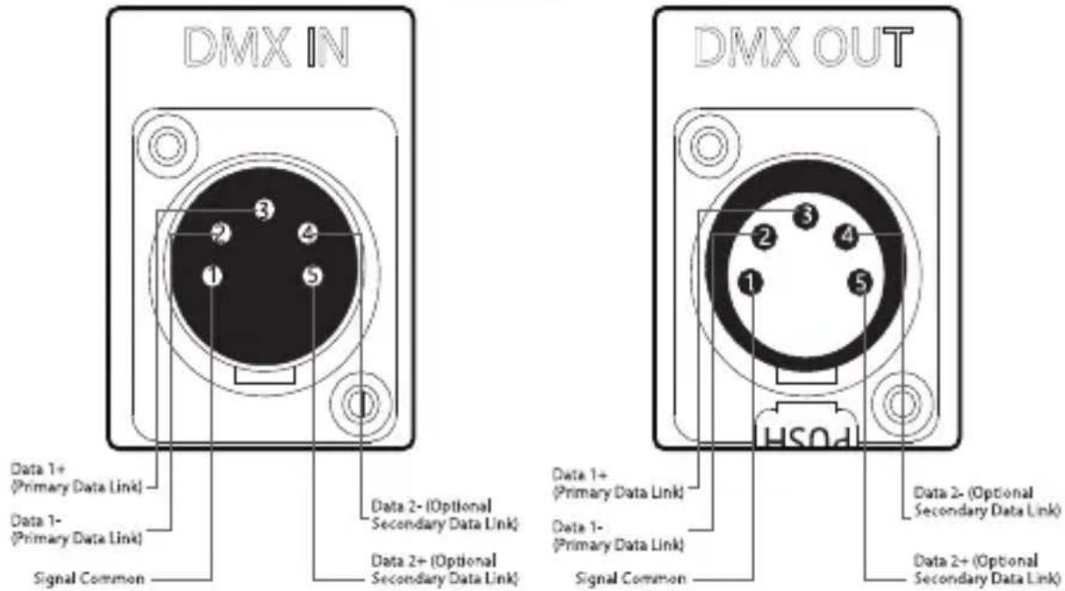
text_image
DMX IN Data 1+ (Primary Data Link) Data 1- (Primary Data Link) Signal Common Data 2- (Optional Secondary Data Link) Data 2+ (Optional Secondary Data Link) DMX OUT Data 1+ (Primary Data Link) Data 1- (Primary Data Link) Signal Common Data 2- (Optional Secondary Data Link) Data 2+ (Optional Secondary Data Link)2) DMX Control
In DMX mode, match the channel of your DMX controller with the light, and then adjust accordingly.
* The default DMX channel is "001".
* The range of DMX channels is 1 to 512.
5. Controlling Effects Via DMX
1) Connect the DMX controller's OUTPUT to the 300d II's controller INPUT as shown in the figure below.
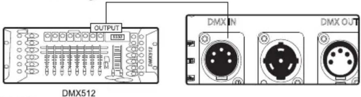
text_image
OUTPUT DMX512 DMX IN DMX OUT2) DMX control
| DMX Channel Values / Functions (5 DMX Channels) | ||
| Channel | Value | Function |
| 1 | Dimmer | |
| 0-255 | Intensity 0 to 100% | |
| 2 | Mode Selection | |
| 0-127 | Manual Mode | |
| 128-255 | FX Mode | |
| 3 | FX Control | |
| 0-19 | Paparazzi | |
| 20-39 | Fireworks | |
| 40-59 | Fault Bulb | |
| 60-79 | Lightning | |
| 80-99 | TV | |
| 100-119 | Pulsing | |
| 120-139 | Strobe | |
| 140-159 | Explosion | |
| 160-255 | Undefined | |
| FX Frequency Control | ||
| 0-19 | 1 | |
| 4 | 20-39 | 2 |
| 40-59 | 3 | |
| 60-79 | 4 | |
| 80-99 | 5 | |
| 100-119 | 6 | |
| 120-139 | 7 | |
| 140-159 | 8 | |
| 160-179 | 9 | |
| 180-199 | 10 | |
| 200-219 | R | |
| 220-255 | Undefined | |
| 5 | IN Lightning mode | |
| 0 | Start Point | |
| 1-127 | Single Trigger | |
| 128-255 | Cycle Mode | |
| IN Explosion Mode | ||
| 0 | Start Point | |
| 1-127 | Single Trigger | |
| 128-255 | Undefined |
* In DMX mode, intensity and FX frequency can only be controlled by a DMX controller.
* Controlling multiple lights using DMX: When controlling multiple 300d II lights independently (i.e., A and B), offset each light by 5 channels. If you set light A at DMX 001, set light B at DMX 006, to control A via CH 1 to CH 5 and to control B via CH 6 to CH 10 on the DMX controller.
Specifications
| Operating Current | 3.5A | Power Consumption | 350W maximum | |
| Power Supply | AC 100~240V 50/60Hz | Cooling Mode | Active Cooling | |
| TLCI | ≥96 | CQS | ≥95 | |
| CRI | ≥96 | Color Temperature | 5500K ±200K | |
| Radio Frequency | 2.4GHz | Channels | 1/2/3 | |
| Groups | A/B/C/D | Remote Ability | ≤100m | |
| Battery requirement | 12V-16.8V ≥15A | APP Control Type | Bluetooth | |
| Sizes (L*W*H) | Light | 29.84*21.56*34.45cm / 11.75*8.49*13.56in | ||
| Controller box Anton Bauer Battery | 27.86*12.67*8.73cm / 10.97*4.99*3.44in | |||
| Controller box (V-Mount) | 27.86*12.67*9.67cm / 10.97*4.99*3.81in | |||
Photometric
| Distance | 1m | 3m | 5m |
| Footcandles | 4182 | 325 | 112 |
| LUX | 45000 | 3500 | 1200 |
*This is an averaged result with reflector, the number might be slightly different on each light.
Trademarks
Bowens is a trademark registered by Bowens in China and other countries.
Anton Bauer is a trademark registered by Anton Bauer in the US and other countries.
Neutrik ^ is a trademark registered by Neutrik ^ in the US and other countries.
Aputure®
GUARANTEE CARD
| Serial No. | |
| Item Name | |
| Purchase Date | |
| Buyer Name | |
| Buyer Phone | |
| Buyer Add | |
| Franchiser Seal |
Aputure Imaging Industries Co., Ltd. Add: F/3, Building 21, Longjun industrial estate, HePing West Road, Shenzhen, Guangdong E-MAIL: cs@aputure.com Sales Contact: (86)0755-83285569-613
- The product identification or serial No. label is removed or defaced in any way. - The product is serviced or repaired by any one other than Aputure or an authorized Aputure dealer or service agency.
- Damage that is the result of misuse, abuse, accident (including but not limited to damage by water), faulty connection, defective or maladjusted associated equipment, or the use of the product with equipment for which it was not intended. - Cosmetic defects that appear more than thirty (30) days after the date of purchase. Cosmetic damage caused by improper handling is also excluded. - Damage that occurs while the product is being shipped to whoever will service it.
Important: Keep your original sales receipt. Be sure the dealer has written on it the date, serial No. of the product. This information is required for warranty service. This warranty does not cover:
Aputure Imaging Industries Co., Ltd. warrants the original consumer purchaser from defects in material and workmanship for a period of one (1) year after the date of purchase. For more details of warranty visit www.aputure.com