ML420 - Luftbefeuchter Munters - Kostenlose Bedienungsanleitung
Finden Sie kostenlos die Bedienungsanleitung des Geräts ML420 Munters als PDF.


Benutzerfragen zu ML420 Munters
0 Frage zu diesem Gerät. Beantworten Sie die, die Sie kennen, oder stellen Sie Ihre eigene.
Eine neue Frage zu diesem Gerät stellen
Laden Sie die Anleitung für Ihr Luftbefeuchter kostenlos im PDF-Format! Finden Sie Ihr Handbuch ML420 - Munters und nehmen Sie Ihr elektronisches Gerät wieder in die Hand. Auf dieser Seite sind alle Dokumente veröffentlicht, die für die Verwendung Ihres Geräts notwendig sind. ML420 von der Marke Munters.
BEDIENUNGSANLEITUNG ML420 Munters
Usermanual
ML420,ML690,MLT800
ML1100,ML1350,MLT1400
natural_image
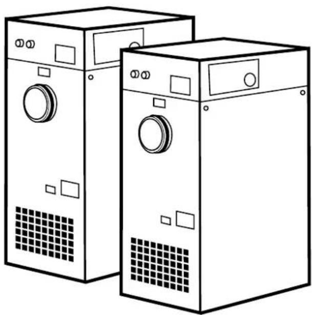
Line drawing of two industrial washing machines with control panel and buttons (no text or symbols)Desiccantdehumidifier
190TGB-1035-H1604©MuntersEuropeAB2016
Importantuserinformation
Intendeduse
Muntersdehumidifiersareintendedtobeusedforthe dehumidificationofair.Anyotheruseoftheunit,or usewhichiscontrarytotheinstructionsgiveninthis manual,cancausepersonalinjuryanddamagetotheunit andotherproperty.
Nomodificationofthcunitisallowedwithoutprior approvalbyMunters.Attachmentorinstallation ofadditionaldevicesisonlyallowedafterwritten agreementbyMunters.
Warranty
Thewarrantyperiodisvalidfromthedatetheunit leftourfactory,unlessotherwisestatedinwriting. Thewarrantyislimitedtoafreccexchangeofpartsor componentswhichhavefailedasaresultofdefectsin materialsorworkmanship.
Allwarrantyclaimsmustincludeproofthatthe faulthasoccurredwithinthewarrantyperiodand thattheunithasbeenusedinaccordancewiththe specifications.Allclaimsmustspecifytheunitytypeand fabricationnumber.Thisinformationisstampedonthe identificationplate,seesectionMarking.
Itisaconditionofthewarrantythattheunitforthefull warrantypperiodisscerviccdandmaintaineddbyaqualified MuntersenginccrorMuntersapprovedengincer. Accesstospecificandcalibratedtestequipmentis necessary. Theserviceandmaintenancemustbe documentedforthewarrantytobevalid.
AlwayscontactMuntersforserviceorrepair. Operating faultscanoccurifthcunitismaintainedinsufficiently or incorrectly.
Safety
Informationaboutdangersareinthismanualindicated bythecommonhazardsymbol:

WARNING! ARNING!
Indicates a possible danger that can lead to personal injury.

CAUTION! UTION!
Indicatesapossibledangerthatcanleadtodamagetothe unitorotherproperty,orcauseenvironmentaldamage.
NOTE!Highlightssupplementaryinformationforoptimal useoftheunit.
ConformitywithDirectives
The dehumidifier is inconformity with the essential safety requirement of the Machinery Directive 2006/42/EC, and in conformity with the provisions of the Ecodesign Directive (ErP) 2009/125/EC, and of the EMCDirective 2004/108/EC. The dehumidifier is manufactured by an organization certified according to ISO9001 and ISO14001.
Copyright
Thecontentsofthismanualcanbechangedwithout priornotice.
NOTE! Thismanualcontainsinformationwhichis protectedbycopyrightlaws.Itisnotallowedtoreproduceor transmitanypartofthismanualwithoutwrittenconsentfrom Munters.
Please send any comments regarding this manual to:
MuntersEuropeAB
TechnicalDocumentation
P.O.Box1150
SE-16426KISTASweden
e-mail:t-doc@munters.se
Tableofcontents
Importantuserinformation......ii
Intendeduse.... ii
Warranty...... ii
Safety.... ii
ConformitywithDirectives...... ii
Copyright.... ii
Tableofcontents......iii
1 Introduction....1
1.1 About this manual.... 1
1.2Unintendeduse.... 1
1.3 Safety and cautions.... 1
1.4 Markings.... 3
1.5Supervisionofoperation.... 3
1.6 Faultindications.... 3
2Dehumidifierdesign....4
2.1Productdescription.... 4
2.2Functiondescription.... 4
2.3Maincomponents.... 5
3Transport,inspectionandstorage......6
3.1 Transport.... 6
3.2 Inspection of delivery.... 6
3.3 Storing the equipment.... 6
4Installation....7
4.1 Safety....7
4.2 Siterequirements.... 7
4.3Foundation.... 8
4.4Mirrorhandedductconnections..... 8
4.5Ductinstallation....9
4.5.Generalrecommendations... 9
4.5.Ductforoutdoorairinlet..... 12
4.5.Buctforwetairoutlet.... 12
4.6Precautionarymeasuresforunitswith Lldesiccantrotor.... 13
4.7 Electrical connections.... 13
4.8Externalhumiditysensor.... 13
4.9Gasreactivation(ML1100units only).... 14
Commissioning....15.
5.1 Settingsbeforestart-up..... 15
5.1.Continuousprocessairfan operation.... 15
5.1.Single-stagehumiditysensor 15
5.1. Two-stagehumidity sensor... 15
5.1. Remotefaultindication..... 15
5.2Pre-startchecks.... 16
5.3Airflowcheckandadjustment..... 17
Operation....18.
6.1 General.... 18
6.2Quickstop.... 18
6.3Beforestarting.... 18
6.4Operatorpanel.... 19
6.5RH98operatorpanel.... 21
6.6Operatingtheunit.... 21
6.6.Manualmode.... 21
6.6.Automaticmode-humidity sensorconnected.... 22
6.6.Automaticmode-RH98or
VariDry(option).... 22
7Serviceandmaintenance......24..
7.1 Safety.... 24
7.2General.... 24
7.3Serviceoptions.... 24
7.4Extendedwarranty.... 25
7.5Cleaning.... 25
7.6Serviceandmaintenanceschedule 25
7.7Filterchange.... 27
Faultracing....28.
8.1General.... 28
8.2 Safety.... 28
8.3Faulttracinglist 29
Technicalspecification.....31...
9.1 Dimensionsandservicespace.... 31
9.2Capacitydiagrams.... 32
9.3Technicaldata.... 34
9.4Sounddata.... 36
9.4.\$ounddataML420...... 36
9.4.2ounddataML690.... 37
9.4.SoundataMLT800.... 37
9.4.SoundataML1100.... 38
9.4.SoundataML1350.... 38
9.4.SounddataMLT1400..... 39
10Scrapping....40.
Appendix1Options......41
1.1General.... 41
1.2Runningtimemeter.... 41
1.3Rotorstopalarm.... 41
1.4Blockedfilteralarm.... 41
1.5Filterbox-M5andF7.... 41
1.6 Humidity control system.... 42
1.6.1 Introduction.... 42
1.6.2Transmitter 42
1.6.3Controlunit.... 42
1.6.4 Setpointsandcontrol parameters.... 43
1.6.5 Display/changesetpointfor relativehumidity.... 44
1.6.6Display/changeother parameters.... 44
1.6.7Processalarms.... 47
2ContactMunters....49
1Introduction
1.1 About this manual
This manualis written for the user of the dehumidifier. It contains necessary information for how to install and used the dehumidifier in a safe and efficient way. Read through the manual before the dehumidifier is installed and used.
Contact your nearest Munters office if you have any questions regarding the installation or the use of your dehumidifier.
This manual must bestored in a permanent location closetothedehumidifier.
1.2Unintendeduse
- Thedehumidifierisnotintendedforoutdoorinstallation.
- Thedehumidifierisnotintendedforuseinclassifiedareaswhereexplosionsafetycompliantequipment isrequired.
- Thedehumidifiermustnotbeinstallednearanyheatgeneratingdevicesthatcancausedamagetothe equipment.
1.3 Safety and cautions
Everymeasurehasbeentakeninthedesignandmanufactureofthedehumidifiertoensurethatitmeetsthe safetyrequirementsofthedirectivesandstandardslistedintheECDeclarationofConformity.
The information in this manual shall in now a way take precedence cover individual responsibilities or local regulations.
During operation and other work with machine it is always the responsibility of the individual to consider the following:
■Thesafetyofallpersonsconcerned.
■Thesafetyoftheunitandotherproperty.
■The protection of the environment.
The types of danger that are indicated in this manual are described in the section Important user information.

WARNING! ARNING!
-Theunitmustnotbesplashedwithorimmersedinwater.
-Theunitmustneverbeconnectedtoavoltageorfrequencyotherthanthatforwhichitwasdesigned. Refertothe identificationplate.Linevoltagethatistoohighcancauseanelectricalshockhazardanddamagetotheunit.
-Donotinsertfingersoranyobjectsintotheairvents.
-Allelectricalinstallationsmustbecarriedoutbyaqualifiedelectricianandinaccordancewithlocalregulations.
-Thedehumidifiercanrestartautomaticallyafterapowercut.Alwayssetandlockthemainpowerswitchinthe OFFpositionbeforecarryingoutanyservicework.
-Useonlyapprovedliftingequipmenttopreventpersonalinjuryanddamagetotheequipment.
-AlwayscontactMuntersforserviceorrepair.
1.4 Markings
text_image
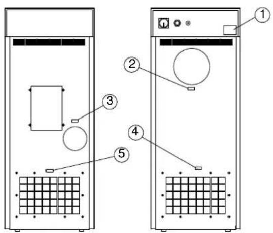
Diagram of two server rack units with labeled components, showing front and side views with numbered annotations.Figure1.1 Identificationplateandmarkings
text_image
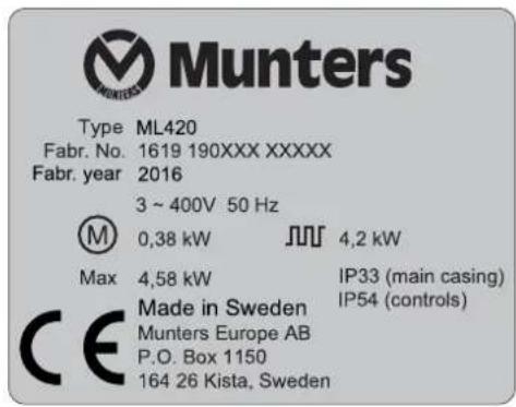
Munters Type ML420 Fabr. No. 1619 190XXX XXXXX Fabr. year 2016 3 ~ 400V 50 Hz M 0,38 kW JUJ 4,2 kW Max 4,58 kW IP33 (main casing) CE Made in Sweden Munters Europe AB P.O. Box 1150 164 26 Kista, Sweden IP54 (controls)Figure1.2 Identificationplate, example
flowchart
graph TD
    A["Step 2: Leftward flow"] --> B["Step 3: Rightward flow"]
    B --> C["Step 4: Leftward flow"]
    C --> D["Step 5: Rightward flow"]
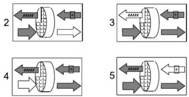
Figure1.3 Labelsforairinletsandoutlets
- Unitidentificationplate
4.Processairinlet - Dryairoutlet5. Reactivationairinlet
3.Wetairoutlet
Explanation of "Fabr.no" on the identification plate:
09=yearofmanufacture,19=weekofmanufacture,190XXX=articlenumber,XXXXXX=serialnumber
1.5Supervisionofoperation
The dehumidifier is controlled and monitored using the operator panel allocated on the front of the unit.
1.6 Faultindications
Faults are clearly indicated on the operator panel, see section 6.4, Operator panel.
Alarmsrelatingtorelativeairhumidityaregiveninthedisplayofthehumiditycontrolsystem(ifinstalled), seeappendix1.6,Humiditycontrolsystem.
2Dehumidifierdesign
2.1Productdescription
ThedesiccantdehumidifiersintheMLserieshavebeendevelopedtoeffectivelydehumidifytheairin environmentsrequiringlowairhumidity.
The dehumidifierisequipped with an encapsulated rotor unit. Therotorcasing is constructed of durable thermosetplastic and contains isolated section that provide a precise balance for the dehumidification, reactivation and heat recovery airflows.
The dehumidifieris manufactured in accordance with uniform European standards and established requirements for CE-marking.
2.2Functiondescription
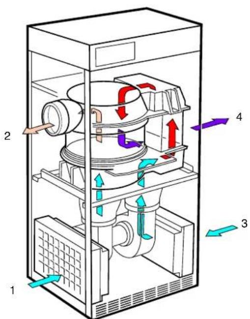
text_image
Technical diagram of a mechanical device with numbered components and directional arrows indicating flow or movement.Figure2.1Internalairflows
1.Processair
2.Dryair
- Reactivation air
4.Wetair
Thedesiccanrotoristheadsorptiondehumidifyingcomponentintheunit. Therotorstructureis comprisedofalargenumberofsmallairchannels.
The desiccantrotorismade of a compositematerial that is highly effective in attracting and retaining water vapour. Therotor is divided into two zones. The airflow to be dehumidified process air, passes through the largest zon of the rotor and then leaves the roton's dry air. Sinc atherotor rotates slowly, thin coming air always meets sadryzone on therotor, thus creating a continuous dehumidification process.
The airflow that is used to dry the rotor, reactivation air, is heated. The activation passes through the rotor in the opposite direction to the process and leaves the rotor as wet air (warm, moist air). This principle enables the dehumidifier to work effectively, even at freezing temperatures.
2.3Maincomponents
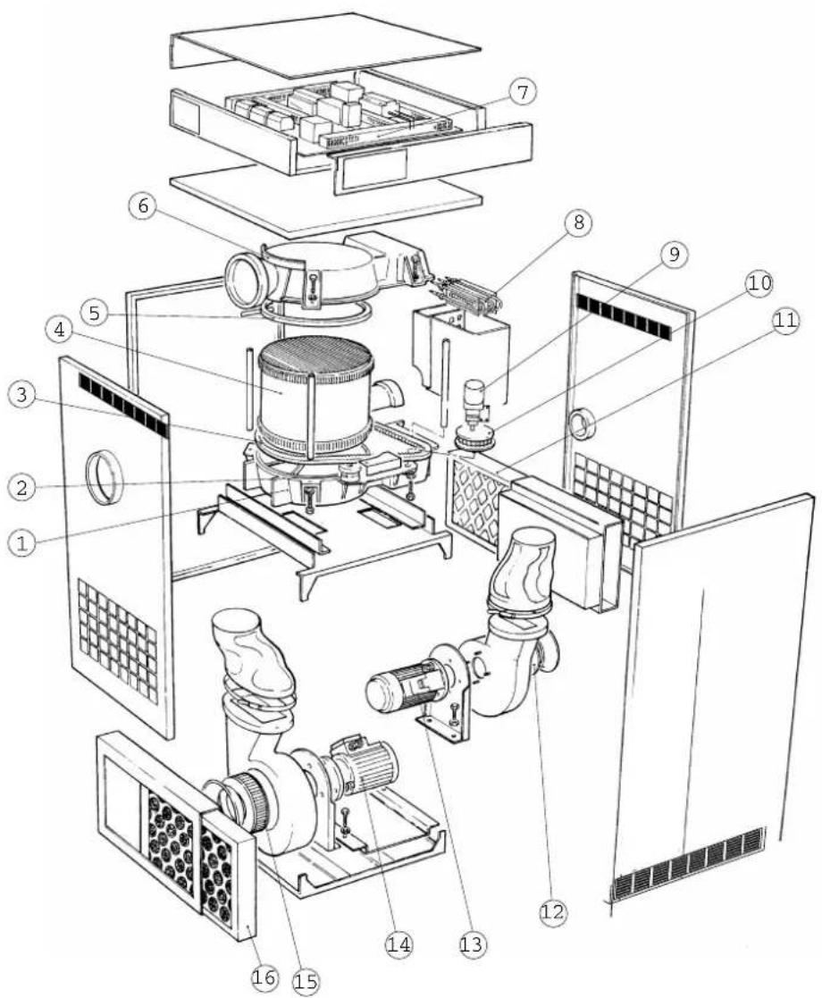
text_image
Exploded view diagram of a mechanical device with numbered components for identificationFigure2.2Maincomponents
- Lowerrotorcover9. Drivemotor
- Roller, beltguide 10. Pulley, beltdrive
3.Drivebelt11. -
Rotor12. Reactivationairimpeller
-
Sealingring, rotor
6.Upperrotorcover14.
-
Electricalcontrolpanel15.Processairimpeller
-
Reactivationheater16.
Reactivationairfilter
- Reactivation fan motor
Processfanmotor
Processairfilter
NOTE! The ML 420 unithasonly one fan motorthatis placed between the process and reactivation impeller.
3Transport,inspectionandstorage
3.1 Transport
The chhumidifier is delivered on apallet and must be handled carefully. All paneldoor son the unit must be closed during transport. Provided that the chhumidifier is still secured to its delivery pallet, it can be removed using a fork-lift truck.

WARNING! ARNING!
Movethedehumidifiercarefullyasthereisariskofthedehumidifiertippingover.

natural_image
Silhouette of a forklift carrying a box (no text or symbols)Figure3.1 Correctlengthonforkliftarms
Weight of the humidifier can be found in section 9.1, Dimensions and service space.
3.2 Inspectionofdelivery
- Doaninspectionofthedeliveryandcomparewiththedeliverynote,orderconfirmationorotherdeliverydocumentation.Makesurethateverythingisincludedandnothingisdamaged.
- ContactMuntersimmediatelyifthedeliveryisnotcompleteordamagedinordertoavoidinstallation delays.
- Remove all packaging material from the unit, and makes sure that nodamage has been made during transportation.
- AnyvisibledamagemustbereportedinwritingtoMunterswithin3daysandpriortoinstallationoftheunit.
■Discardthepackagingmaterialaccordingtolocalregulations.
3.3 Storing the equipment
Followtheseinstructionsifthedehumidifieristobestoredpriortoinstallation:
- Placethedehumidifierinanuprightpositiononahorizontalsurface.
■Re-usethepackagingmaterialtoprovideprotectionfortheunit.
■Protectthedehumidifierfromphysicaldamage.
■Storethedehumidifierundercoverandprotectitfromdust,frost,rainandaggressivecontaminants.
4Installation
4.1 Safety

WARNING! ARNING!
-Theunitmustnotbesplashedwithorimmersedinwater.
-Theunitmustneverbeconnectedtoavoltageorfrequencyotherthanthatforwhichitwasdesigned.Refertothe identificationplate.Linevoltagethatistoohighcancauseanelectricalshockhazardanddamagetotheunit.
-Donotinsertfingersoranyobjectsintotheairvents.
-Allelectricalinstallationsmustbecarriedoutbyaqualifiedelectricianandinaccordancewithlocalregulations.
- Thedehumidifier can restart automatically after a power cut. Always set and lock them in power switch in the OFF position before carrying out any service work.
-Useonlyapprovedliftingequipmenttopreventpersonalinjuryanddamagetotheequipment.
-AlwayscontactMuntersforserviceorrepair.

CAUTION! UTION!
Thewetairductmustalwaysbeinsulatedwhenthereisariskoffreezing.Condensationbuildsupeasilyonthe insideoftheductbecauseofthehighmoisturecontentofthewetairleavingthedehumidifier.

CAUCTION! UTION!
The dehumidifier has been designed to operate at specific process air flows corresponding to the fansizes installed.
4.2 Siterequirements
The dehumidifier is only intended for indoor installation. Avoid installing the dehumidifier in a dam environment where there is a risk of water entering the unit or in a very dusty environment. If doubt, contact Munters. It is important that the intended installations item meet the location and space requirements for the equipment in order to achieve the best possible performance.
For the unit dimensions and services space requirements, see section 9.1, Dimensions and Servicespace.
NOTE!thereisaneedforreductionofvibrationsfromthedehumidifier,contactMuntersforinstructions.
4.3Foundation
The dehumidifier must be installed on a level floor, or on a platform capable of supporting the machine weight. If the maximum floor loading weight is not exceeded, special foundations are not required.
Whenthedehumidifierhasbeeninstalled,checkthatitislevel.
If local regulations require that the unit is permanently fixed in position, the fixing holes can be used for bolting the unit to the floor.
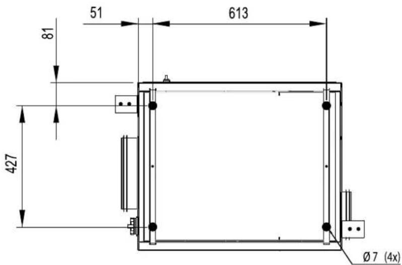
text_image
51 613 81 427 Ø7 (4x)Figure4.1 Drilling pattern
4.4 Mirrorhandedductconnections
Thefrontandrearpanelsareinterchangeable,sothattheconnectionsforprocessairanddryairmaybe situatedeitherontheleftorrightsideoftheunit.
The dehumidifiers are delivered with the process and dry air connections on the left side of the unit. If it is required to change the orientation, so that the connections are contherights side of the unit, proceed as follows.

WARNING! ARNING!
Makesurethatthedehumidifierisdisconnectedfromthemainspowerbeforechangingthepositionsofthe processairanddryairconnections.
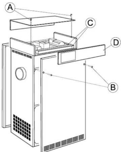
text_image
Technical diagram of a refrigerator with labeled parts A, B, C, and D indicating different internal compartments or components.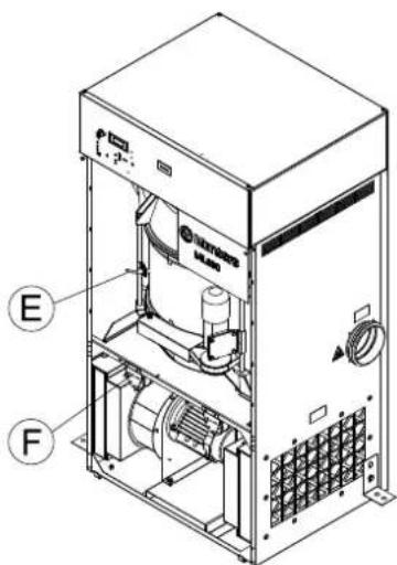
text_image
E FFigure4.2 Changing panel positions Figure4.3 Rotorstop (E) and filter monitors (F)
- Removethetwobolts(B)securingthefrontpanelandcarefullyremovethepanel.
- Removethetwoboltssecuringtherearpanelandcarefullyremovethepanel.
- Removethetwobolts(A) and washerssecuringthecontrolandtoppanels, then carefully remove the toppanel.
- Removethecableductcovers(C), re-routethecables and fitthecontrol panel(D) onto the oppositeside of the unit. Refitthecableduct covers.
- Loosentherotorstop(E) and the two filter monitors(F). Removetheableties.
6.Fittherotorstopandfiltermonitorsontheoppositesideoftheunit.Tiethecables.
7.Fitthefront, rearandtoppanelsintheirnewpositions.
4.5Ductinstallation
4.5.1 General recommendations
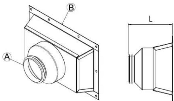
The connections for process and reactivation air are designed in accordance with there recommendations in ISO13351. The rectangular duct connections contain attached inserts for M8 screws.
text_image
Technical drawing of a mechanical component with labeled parts A and B, including a detailed cross-section view labeled L.Figure4.4Ductconnections
| Partnumber170-013448-005170-013448-004170-013448-003170-013448-002170-013448-001 | |||||
| A | ∅100∅125∅160∅200∅250 | ||||
| B | Seesection9.1,Dimensionsandservicespace. | ||||
| L(mm) | 210210200140150 | ||||
| ML420XX | |||||
| ML690XX | |||||
| MLT800XX | |||||
| ML1100XX | |||||
| ML1350XX | |||||
| MLT1400XX | |||||

CAUTION!
UTION!
The dehumidifier has been designed to operate at specific process airflows corresponding to the fansizes installed.
The process and dry air ducts should be the same diameter. The same applies to the reactivation air and wet air ducts.
The length of ductwork must be kept short as possible to minimise static pressure losses.
Tomaintainperformanceallrigidprocessoreactivationinductworkjointsmustbeairandvapourtight.
The process is ductwork must be insulated to prevent condensation developing on the outside of the duct, whenever the temperature of the air within the duct falls below the dewpoint temperature of the ambient air through which the ductwork is routed.
Theductsmustalwaysbeinsulatedwhentherecisariskoffreezing.
The wetainleavingthedehumidifierwill,becauseofhighmoisturecontentcondenseontheinsideduct walls.Byinsulatingtheductstheamountofcondensatesreduced.
Horizontalwetainductsmustbeinstalledwithslightdeclinc(awayfromthedchumidifier)todrain awaypossiblecondensationSuitablecondensationdrainsmustbeinstalledatlowpointsinthewet airoutletduct,see Figure4.7.
Ensure that access for operation and servicing is not restricted when designing and installing ducting. Form or information, reference section 9.1, Dimensions and Service space.
Toreducenoise and/or vibration being transmitted along rigid ducts good quality, airtight flexible connection scan be fitted.
Ductsmounteddirectlyontotheunitmustbeindependentlysupportedominimisethloadontheunit.
DampersforadjustingtheairflowsmustbeinstalledinthesupplyairoutletandreactivationairinletductsCorrectairflowsaressentialforthoperatingefficiencyofthunitForairflowadjustmentinstructions,seesection5.3,Airfloncheckandadjustment.
The total pressure drop in the process and reactivation during work must not exceed the available pressure of the fans fitted to the dehumidifier. For detail of minimum available static pressure, see section 9.3, Technical data.
text_image
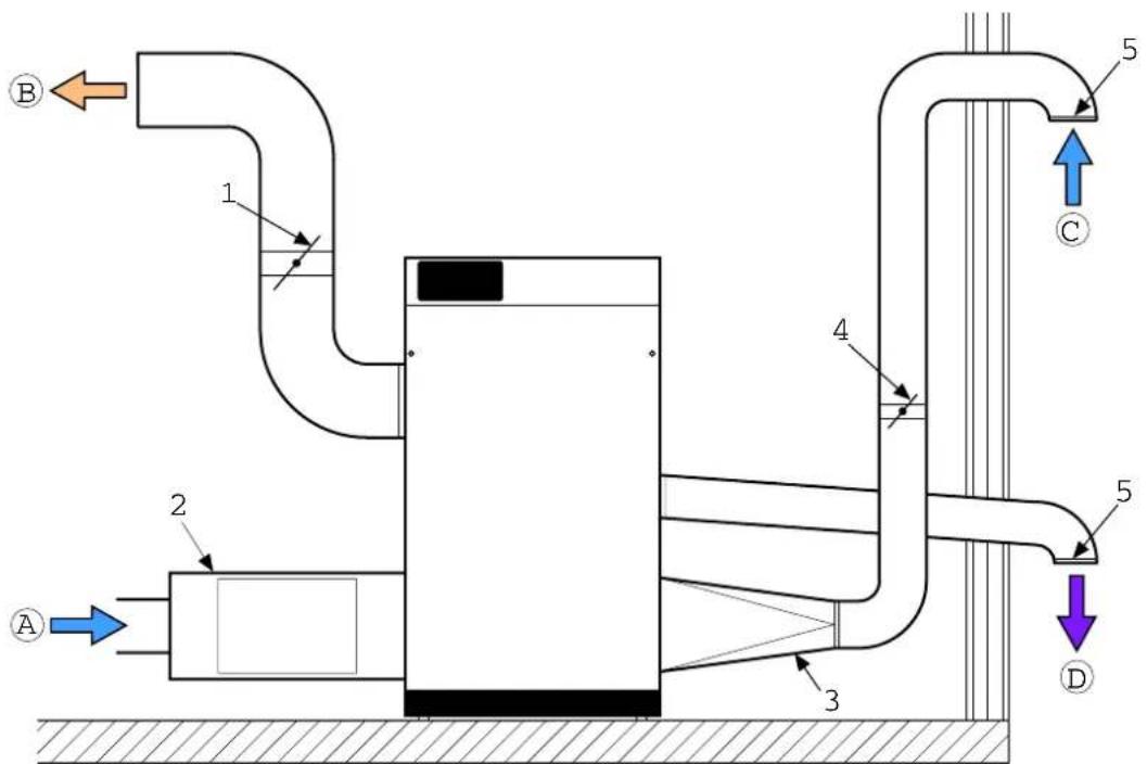
Technical schematic diagram of a fluid system with labeled components and flow directionsFigure4.5 Ductsrequiredforinstallation
A.Processairinlet1.Dryairdamper
B. Dryairoutlet
- Externalfilterbox(option)
C. Reactivationairinlet
3.Ducttransition
D. Wetairoutlet4. Reactivationairdamper
- Outlet/inletduct(wirenetting)
4.5.2 Ductforoutdoorairinlet
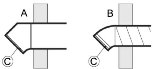
When bringing ambient air from outdoors into the dehumidifier, the inlet duct opening must be located sufficiently high above ground level to prevent dust and debris from entering.
The ducting must be designed to prevent train and snow from being drawn into the dehumidifier. The air inlet must be located away from possible contaminant such as engine exhaust gases, steam and harmful vapours.
Topreventthewet(outlet)airfromhumidifyingthereactivation(inlet)air,theairinletforreactivationmustbelocatedatleast2mfromthewetairoutlet.
Attachawirenetwithameshwidthofapproximately10mmintheouterendoftheducttopreventanimals fromenteringthedehumidifierducting.
text_image
A B CFigure4.6 Outdoorairinletdesign
A. Rectangularducting
B. Roundducting
C.Wirenetting
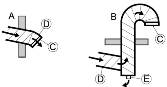
4.5.3 Ductforwetairoutlet
Thematerialforthewetairductmustwithstandcorrosionandtemperaturesofupto100°C. Thewetair ductingmustalwaysbeinsulatedifthereisariskofcondensation. Thewetairleavingthedehumidifierwill easilycausecondensationontheinsideoftheductwallsduetothehighmoisturecontent.
Horizontalductsmustbeinstalledslopingdownwards(awayfromthedehumidifier)todrainawaypossible condensation. Theductslopemustbeatleast2cm/m. In addition, drainageholes(5mm)shouldbemadeat lowpointsintheducttopreventwateraccumulation.
Attachawirenetwithameshwidthofapproximately10mmintheouterendoftheducttopreventanimals fromenteringthedehumidifierducting.
text_image
A D C B C D EFigure4.7Wetairoutletdesign
A. Horizontalwetairoutlet
B. Verticalwetairoutlet
C.Wirenetting
D.Downwardslope
E.Condensatedrainage
4.6PrecautionarymeasuresforunitswithLIdesiccantrotor
The standard delivery is Munters high performance desiccant rotor HPS (High Performance Silicagel). If the chumidifier is delivered with an Lrotor (lithium chloride) it is important that the rotordoes not be comeloaded with moisture when the chumidifier is off.
NOTE! Makesurethatnoairpassingthroughtherotorhasarelativehumiditygreaterthan80%.
It is recommended to install closing dampers in the process and reactivation air inlet to avoid that air with high relative humidity is drawn through therotor and intotheroom.
Thisisparticularlyimportantwhentheprocessairisdrawnfromoutdoors,orwhenthesystemhasbeen fittedwithapre-cooler.
4.7 Electrical connections

WARNING! ARNING!
Allelectricalequipmentconnectionsmustbecarriedoutinaccordancewithlocalregulationsandbyqualified personnel.Riskofelectricalshock.

WARNING! ARNING!
Theunitmustneverbeconnectedtoavoltageorfrequencyotherthanthatforwhichitwasdesigned. Refertothe unitidentificationplate.
Eachunitissuppliedcompletewithalltheinternalwiringinstalledandconfiguredinaccordancewiththe specifiedvoltageandfrequencyontheidentificationplate.
NOTE! Thesupplyvoltagemustnotdifferfromthespecifiedoperatingvoltagebymorethan+/-10%.
For connection details, such identification plate and the wiring diagram section 9.3, Technicallata.
4.8 External humidity sensor
ML-seriesdehumidifiersarewiredsothatwhentheunitissettoAUTOMATIC;canbecontrolledfromanexternallymountedhumiditysensor.
Allmodelshavcatwo-stagechater, and can be controlled by two-stagehumidity sensor. This method is more efficient and allows for more accurate dehumidification control.
The electrical connections are made at terminals in the electrical control panel. For wiring and connection details, seethewiring diagram.
NOTE! Where no humidity sensor is connected to the unit, the dehumidifier will be operating at maximum output for as long asthe unit is switched on.
Aroomhumidity sensoristobemounted1-1.5mabovethefloor.Itmustbepositionedsothatitisnot directlyexposedtodryairfromtheunitortohumidairflowinginthroughopeningdoors.Positionitaway fromheatsourcesanddirectsunlight.
■The humidity sensor connecting cables should have a conductor area of not less than 0.75mm ^2 and must have an insulation resistance rating in excess of 500VAC.
- The humidity sensor must be designed so that the contacts close on arising RH to complete the control circuit and start the humidifier.
■Voltagedropscanoccurwhenusingexcessivelylongcables.
If the voltage acrosstheterminals used for connecting the humidity sensor is less than 20 VAC, a separate relay controlled by the humidity sensor must be used.
4.9Gasreactivation(ML1100unitsonly)
For further information on installation, start-up and maintenance of gas burners, see appendix about gas reactivation provided with the unit.
5Commissioning
The ML420-MLT1400 dehumidifiers have several standard functions that need to be set before initial start-up. Some of the functions require connection to externale equipment.
Somefeaturesrequireconnectionofexternalequipment.Forwiringdetails,seethewiringdiagram.
5.1 Settingsbeforestart-up
5.1.1 Continuous process air fan operation
Standardsettingsautomaticallyactivatetheprocessairfanonlywhendehumidificationisrequired. However,continuousprocessairflowcanbedesirableevenwhendehumidificationisnotrequired. Continuousprocessairflowcanbeset,seethewiringdiagram.
5.1.2 Single-stage humidity sensor
NOTE! When no humidity sensor is connected, the dehumidifier will run at maximum effect continuously.
Ifasingle-stagehumiditysensorisfitted,thiswillswitchthedehumidifieronandoff.Asingle-stage humiditysensorisconnectedaccordingtothewiringdiagram.
Tomaintainair circulation, preselect continuous operation of the process airfane event though dehumidification is not required. For further information, see section 5.1.1, Continuous process airfampation.
5.1.3 Two-stage humidity sensor
NOTE! When no humidity sensor is connected, the dehumidifier will run at maximum effect continuously.
If two-stage humidity sensor is connected, this will control the reactivation heater in two stages. The reactivation power is controlled on the basis of the humidity sensor reading and the set point. At two-stage humidity sensor is connected according to the wiring diagram.
Tomaintainair circulation, preselect continuous operation of the process airfane event though dehumidification is not required. For further information, see section 5.1.1, Continuous process airfampation.
5.1.4 Remotefaultindication
ThePCBdisplaycanbeusedforageneralindicationofthefollowingfaultsonthedehumidifier:
■Processairfan
■Reactivationairfan
-Drivemotor
Heater
■Auxiliaryequipmentinput
■Rotorhasstopped(ifthisoptionisinstalled)
■Blockedprocessairfilter(ifthisoptionisinstalled)
■Blockedreactivationairfilter(ifthisoptionisinstalled)
5.2 Pre-startchecks

WARNING! ARNING!
Installation, adjustments, maintenance and repairs must only be carried out by qualified personnel who are aware of other risks involved when working with the equipment operating with high electrical voltage and high machine temperatures.
Beforestartingthedehumidifierforthefirsttime,ensurethatthemainspowersupplyisisolatedfromthe dehumidifierandcarry-outthefollowingchecks:
Check that the Modeswitchonthodehumidifier is in the "OFF" position, see section 6.4, Operatopanel.
- Check the air intake filters for damage and proper fixation and also check that all areas inside the unit are clean.
- Visually inspectalducting and duct connection stomakesure that all connections have been correctly installed and that there are no sign of damage to the system. Also check that all ducts are free from obstacles blocking the air passage.
- Removethetoppanelandcheckthatnoneofthemaincontactbreakersintheelectricaloperatorpanel havebeentripped. Fordetailsrefertothewiringdiagramsprovidedwiththeunit.
- Check that the incoming powers supply voltage is correct and that the cables are correctly connected.
- Checktherotationdirectionofthefanimpellerafterconnectiontothepowersupply. Openthefront panelofthedehumidifierandtakeouttheprocessfilter.Startthedehumidifierandcheckthatthefan impellerisrotating.Switchoffthedehumidifierandwatchthefanimpellerjustbeforeitstopsrotating. Checkthatitisrotatingclockwise.
- If an external humidity sensor is used, check that the sensor is correctly positioned in the room and is correctly connected to the unit, see section 4.8, External humidity sensor.
- Set the process and reactivation airflow damper to the fully open position.
5.3 Airflowcheckandadjustment
To obtain the design performance, the dry air and reactivation airflow dampers must be correctly adjusted in accordance with therated airflow, see section 9.3, Technical data.
If necessary, contact Munters for assistance concerning installation and settings. Munters contact addresses are provided on the back cover of this manual.

CAUCTION! UTION!
Incorrectlysetprocessandreactivationairflowscancausetheunittomalfunction.
Anydamagetotheunitresultingfromincorrectadjustmentoftheairflowscaninvalidatethewarrantyoftheunit.
Theunitmustnotberunformorethanafewminutesbeforesettingupthecorrectairflows.
- Adjust the dampers installed in the dry air outlet and reactivation air inlet duct to the corrected airflows.
- Start the dehumidifier and run at full power for 8 minutes to allow thereactivation heat retention of heat, normal operating temperature.
- Verify that the temperature difference between the reactivation in let air and the reactivation temperature is 95^ C (tolerancelimit ±5^ C). If the temperature differences outside of the 5% tolerance limit, the reactivation air damper can be adjusted in small steps until the reactivation temperature is within the specified tolerances. Allow the temperature to stabilize after each adjustment.
Example:
Inletairtemperature=15°C
Reactivationairtemperature=110°C
Temperatureincrease=95°C
6Operation
6.1 General
ML420-MLT1400dchumidifiersareequippedwithanoperatorpanelwithamodeselectorswitchandLEDindicators.
Themodeselectoroftheoperatorpanelhastwooperatingpositions:
MAN(Manualmode)
The dehumidifier fans, rotor and reactivation heater operate continuously at full capacity.
AUTO(Automaticmode)
The dehumidifier fans, rotor and reactivation heater operate when the relative humidity exceeds the desired value.
6.2Quickstop
Undernormaloperatingconditions, themodeswitchisusedtostopandstarttheunit. In an emergency situation, stop the dehumidifier using themainpowerswitchontheside.

CAUCION! UTION!
Onlyusethemainpowerswitchtostoptheunitinthecaseofanemergency. Thenormalshutdownsequencewill notbefollowed. Thefansstopandtheheatercanbeveryhot,whichcanresultindamagetotheheaterandother componentsclosetoit.
6.3 Beforestarting
Followtheinstructionsinsections5.2,Pre-startcheckand5.3,Airfloncheckandadjustmenbeforeinitialstart-upofthedehumidifier.
6.4Operatorpanel
natural_image
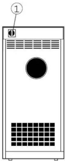
Front view of a white industrial device with a circular vent and grid pattern (no text or symbols)Figure6.1 Mainpowerswitch
text_image
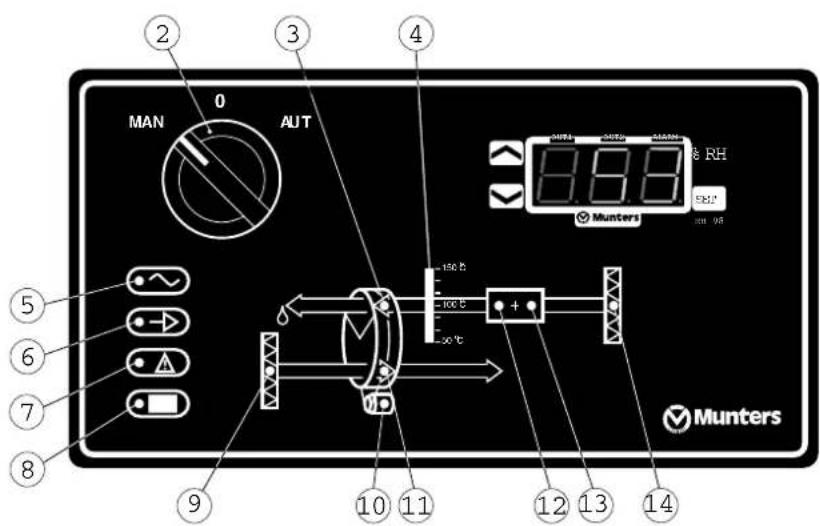
MAN 0 AUT 4 190℃ 100℃ 50℃ ⑤ ⑥ ⑦ ⑧ ⑨ ⑩ ⑪ ⑫ ⑬ ⑭ ⑮ ⑯ ⑰ ⑱ ⑲ ⑳ ⑴ Munters 0.88 RH EBL* 320 08 MuntersFigure6.2Operatorpanelwithbuilt-inRH98
| Item | Switch/Indicator | Function |
| 1MainpowerswitchWhenthemainpowerswitchissetto"0",thereisnopowerinthecontrolcircuit,andtheunitcannotbested.Whenthemainpowerswitchissetto"1",powerissuppliedtothecontrolcircuit,andthedehumidifiercanbesteredusingthemodeswitch. | ||
| 2Modeswitch | Whenthemodeswitchissetto"MAN"thedehumidifierisinmanualmode.Itthenrunscontinuously(fullcapacity).Withthepowerswitchsetto"0",thedehumidifierisswitchedoff.Whenthemodeswitchissetto"AUT"thedehumidifierisautomaticmode.Inthismode,asinglortwostagehumiditysensormustbeconnectedtotheunitifitisnotequippedwithaRH98oraVariDrycontrolsystem.Thehumiditysensor,RH98orVariDrydictateswhenthedehumidifierstopsandstarts. | |
| 3 | ReactivationairfanindicatorThereactivationairfanindicatorlamplightswhenthefanisrunning.Itflashesifthereisafaultinthefan. | |
| 4Reactivationairtemperaturedisplay | Indicatesthereactivationairtemperature. | |
| 5 | Mainsupplyconnectionindicator | Indicatesthatmainssupplyisconnectedtothedehumidifierandthemainpowerswitchissetto"1". |
| 6Unitrunningindicator | Indicatesthattheunitisrunning,orisreadytostartuponasignalfromthehumiditysensor,RH98orVariDry(automaticmode). | |
| 7 | Faultindicator | Aflashingfaultwarningindicatorlampindicatesthattheunithasshut-downduetoa faultinoneofthefollowing:-Processairfan-Reactivationairfan-Drivemotor-Reactivationheater(stage1)(electricreactivationheatermodelsonly)-Reactivationheater(stage2)(electricreactivationheatermodelsonly)-Rotorhasstopped (1)-Auxiliaryequipment (2)Thecorrespondingindicatorsflashtofacilitatefaulttracing.Inaddition,therelay fortheremoteindicationoffaultsisactivated.Forfurtherinformationseesection 8.3,Faulttracinglist. |
| 8Auxiliaryequipmentindicator | Thisisauserdefinedoption.Theindicatorlightsinnormaloperationalmodeand flashestoindicateafault.Thedehumidifierisautomaticallyswitchedoff,andthe faultandremoteindicatorsareactivatedifafaultoccursintheauxiliaryequipment.Forunitsfittedwithanair-cooledcondenser,theauxiliaryequipmentindicatorlamp isonwhenthecondenserisinnormaloperationalmodeandflashesifafaultoccurs inthecondenserfanorheater. | |
| 9 | Processairfilterblocked indicator (1) | Whentheindicatorforblockedprocessairfilterlights,thefilterisblocked.Ablocked filterdoesnotmeanthattheunitmustbeswitchedofforthatthefaultindicatoris activatedTheremotefaultindicator(ifinstalled)isactivatedwhenablockedfilteris detected. |
| 10DrivemotorindicatorThedrivemotorindicatorlamplightswhentherotor'sdrivemotorisrunning.It flasheswhenthereisafaultinthedrivemotorortherotorhasstopped. | ||
| 11 | ProcessairfanindicatorTheprocessairfanindicatorlamplightswhenthefanisrunning.Itflashesifthereisafault. | |
| 12Reactivationheaterindicator(stage1) | Theindicatorlightswhentheheaterstarts.Itflashesifthereisafaultintheheater(stage1). | |
| 13Reactivationheaterindicator(stage2) | Theindicatorlightswhentheheaterstarts.Itflashesifthereisafaultintheheater(stage2). | |
| 14 | Reactivationairfilterblocked indicator (1) | Whentheindicatorforablockedreactivationairfilterlights,thefilterisblocked.Ablockedfilterdoesnotmeanthattheunitmustbeswitchedofforthatthefault indicatorisactivatedTheremotefaultindicator(ifinstalled)isactivatedwhenablockedfilterisdetected. |
| (1)Options.(2)Forunitsfittedwithanair-cooledcondenser,theauxiliaryequipmentindicatorlampisonwhenthecondenserisinnormaloperationalmodeandflashesifafaultoccursinthecondenserfanorheater. | ||
Table6.1 Operatorpanelfunction
6.5RH98operatorpanel
text_image
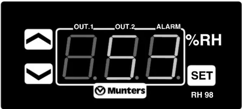
OUT.1 OUT.2 ALARM %RH 8.8.8 SET Munters RH 98Figure6.3RH98operatorpanel
Checkingandchangingsetpointsandcontrolparameterscanbemadeduringoperationorinstand-by mode.
| ButtonFunction | |
| Display/changeacertainvalueandresetthealarm | |
 | Increasethevalue |
 | Decreasethevalue |
| %RH:Displaypositionofcontrolstepsforreactivationheater(0=off;1=on). |
Table6.2RH98operatorpanelfunctions
During normal operation and in any position of the modes switch the current relative air humidity is displayed.
6.6 Operating the unit
6.6.1 Manualmode
Sethemainpowerswitchto"1"(on)andcheckthathemainsconnectionindicationlamplights.
SethemodeswitchonthecontropanetoMAN.Checkthatthefollowingindicatorlampslight:
■Mainsupplyconnectionindicator
■Unitrunningindicator
■Bothindicatorsforthereactivationheater
- Bothprocessairandreactivationairfanindicators
- Drivemotorindicator
- Let the unit run for about 8 minutes to allow the operating condition to stabilize. Then check that the reactivation heater is working (temperature indicator shows the temperature of the reactivation air).
Sethemodeswitchonthecontrollo"0"andcheckthatboththeindicatorlampsforthereactivationheatergoout.
NOTE!nordertodissipateanyresidualheat,thereactivationaifan,processaifanandthedrivemotorwill continuetorun(aftertheunithasbeenswitchedoff)untilthetemperaturehasfallenbelow50°C.
- Check that the process air fan, reactivation air fan and drivemotor indicator go out when the temperature falls below 50^ C, and that the power connected indicator remains on.
Fordetailsontheoperatorpanel, see section 6.4, Operatorpanel
6.6.2 Automaticmode-humidity sensor connected
Asingleortwostagehumiditysensormustbeconnectedfortheunittoberuninautomaticmode. For further information, see section 5.1.2, Single-stagehumiditysensor and 5.1.3, Two-stagehumiditysensor.
- SetthemodeswitchtoAUT.
Adjust the humidity sensor set point to the lowest RH value Set themain powers switch to "1" (on). Check that the following indicator lamps are on and that the unit is running.
■Mainssupplyconnectionindicator
- Unitrunningindicator*
- Bothreactivationheaterindicators*
■Bothprocessairandreactivationairfanindicators*
- Drivemotorindicator*
NOTE! If the current RH value in the room to be de humidified is lower than the set point on the humidity sensor, the above indicators will not light and the de humidifier will not start.
3.Slowlyincreasing the humidity setpoint and check that the units switches off when the setpoint matches the RHintheroom where the humidity sensor is installed.
4.Slowlydecrease the humidity setpoint and check that the units switches on when the setpoint falls below the RHinthroom where the humidity sensor is installed.
Sethemodeswitchonthecontrolto"0"andcheckthatboththeindicatorlampsforthereactivationheatergoout.
NOTE!norderfortheunit'sheaterstocoobown,thereactivationairfanprocessaifanandthedrivemotorwill continuetorun(aftertheunithasbeenswitchedoff)untilthetemperaturehasfallenbelow50°C.
-
Check that the process air fan, reactivation air fan and drivemotor indicator go out when the temperature falls below 50^ Cand the unitis running, and that the power connected indicator remains on.
-
Adjust the humidity setpoint to the desired RH value.
Fordetailsontheoperatorpanel, see section 6.4, Operatorpanel
6.6.3 Automaticmode-RH98orVariDry(option)
If the unit is fitted with a factory installed RH98 or Vari Dry (option) humidity control system, the external humidity sensor must be installed and correctly connected to the unit. The same requirement apply to the humidity sensor and RH98 or Vari Dry section 4.8. External humidity sensor.
Formoreoperationaldetails,seeappendix1.6,Humiditycontrolsystem.
- SetthemodeswitchtoAUT.
AdjusttheRH98orVariDrysetpointtothdowestRHvalue,seesection6.5,RH98operatoropanel.
Sethemainpowerswitchto"1"(on)Checkthathefollowingindicatorlampsareomandthathe unitisrunning.
■Mainsupplyconnectionindicator
■Unitrunningindicator*
- Bothreactivationheaterindicators*
- Bothprocessairandreactivationairfanindicators*
- Drivemotorindicator*
NOTE!*IfthecurrentRHvalueintheroomtobedehumidifiedisbelowthesetpoint(factorysetting50%RHof RH98orVariDry),theaboveindicatorswillnotlightandthedehumidifierwillnotstart.
- Slowly increase the humidity setpoint and check that the units switches off when the setpoint matches the RH in the room where the humidity sensor is installed.
5.Slowlydecrease the humidity setpoint and check that the units switches on when the setpoint falls below the RHintheroom where the humidity sensor is installed.
Sethemodeswitchonthecontrolto"0"andcheckthatboththeindicatorlampsforthereactivationheatergoout.
-
Check that the process air fan, reactivation air fan and drivemotor indicator go out when the temperature falls below 50^ C and the unitis running, and that the power connected indicator remains on.
-
Adjust the humidity setpoint to the desired RH value.
7Serviceandmaintenance
7.1 Safety


Figure7.1 ElectricalbazardFigure7.2 Secureagainstreconnection

WARNING! ARNING!
Adjustments, maintenance and repairs must only be carried out by qualified personnel.

WARNING! ARNING!
Before doing any service or maintenance work on the unit makes sure that all electrical equipment is disconnected from the powers supply, and secured against a connection.
7.2General
Muntersdehumidifiersaredesignedforlong-term,continuoususagewithahighdegreeofreliability. Aswithallmachinery,regularserviceandmaintenanceisrequiredtokeepthedehumidifierinoptimal conditionsothatitworksmostefficiently.
Serviceandmaintenanceintervallengthsareprimarilydeterminedbyoperatingconditionsandthe environmentinwhichtheunitisinstalled. Forexample,iftheprocessaircontainsalotofdust,preventative maintenanceshoubecarriedoutatshorterintervals.Thesamealsoappliesiftheunitworksintensively.
7.3Serviceoptions
Inaddition to commissioning of the unit there are four service options (A-D) as standard.
S. Commissioning/start-up.
A. Inspection and if necessary change off filter. General function check.
B. In addition to A, safety check and capacity, temperature and humidity regulation measurements.
C. In addition to B, preventivereplacement of some components after 3 years of operation.
D. In addition to C, preventivereplacement of some components after 6 years of operation.
NOTE! AlwayscontactMuntersforserviceorrepair. Operatingfaultscanoccuriftheunitismaintained insufficientlyorincorrectly.
NOTE!Commissioning/Start-upinspection"S'byMuntersismandatorytovalidatethefullwarranty.
Muntersserviceengineershavespecialequipmentandrapidsparepartsaccesstohandleservicconall Muntersproducts.Alltestequipmentusedbyourpersonneltoensurepropersystembalancingiscertified foraccuracy.
MuntersServicecanofferaserviceplanadaptedtosuittheconditionsofaspecificinstallation.Seecontact addressesonthebackpageofthismanual.
7.4 Extended warranty
MuntersoffersanextendedwarrantytothestandardtermswhentheCustomersignsaserviceagreement withMunters.Detailsareavailableonrequest.
7.5Cleaning
UseonlyapH-neutralsoapywatersolutionandasoftspongeforcleaningoftheunitcasing.
Whencleaningtheinside, avoidcontactwiththerotorandwipethesurfacesdry.
Useavacuumcleanerwithabrushheadfortherotor.ContactMuntersforinstructionsifvacuumcleaning isnotsufficient.
7.6Serviceandmaintenanceschedule
| Service work | ServiceoptionsABABACABABAD | ||||||||||||||||
| Operatingtimeinhours | |||||||||||||||||
| Calendartimeinmonths | 0 | ||||||||||||||||
| 60 54 48 | 60 54 48 | X | |||||||||||||||
| 60 54 48 | 60 54 48 | X | |||||||||||||||
| X X X X X X X X X X X X X X X X X X X X X X X X X X X X X X X X X X X X X X X X X X X X X X X X X X X X X X X X X X X X X X X X X X X X X X X X X X X X X X X X X X X X X X X X X X X X X X X X X X X X X | Checkandreplacefilterifnecessary,XX XX XX XX XX XX XX XX XX XX XX XX XX XX XX XX XX XX XX XX XX XX XX XX XX XX XX XX XX XX XX XX XX XX XX XX XX XX XX XX XX XX XX XX XX XX XX XX XX XX XX XX XX XX XX XX XX XX XX XX XX XX XX XX XX XX XX XX XX XX XX XX XX XX XX XX XX XX XX XX XX XX XX XX XX XX XX XX XX XX XX XX XX XX XX XX XX XX XX XX XX XXXXXXXXXXXXXXXXXXXXXXXXXXXXXXXXXXXXXXXXXXXXXXXXXXXXXXXXXXXXXXXXXXXXXXXXXXXXXXXXXXXXXXXXXXXXXXXXXXXXXXXXXXXXXXXXXXXXXXXXXXXXXXXXXXXXXXXXXXXXXXXXXXXXXXXXXXXXXXXXXXXXXXXXXXXXXXXXXXXXXXXXXXXXXXXXXXXXXXXXXXXXXXXXXXXXXXXXXXXXXXXXXXXXXXXXXXXXXXXXXXXXXXXXXXXXXXXXXXXXXXXXXXXXXXXXXXXXXXXXXXXXXXXXXXXXXXXXXXXXXXXXXXXXXXXXXXXXXXXXXXXXXXXXXXXXXXXXXXXXXXXXXXXXXXXXXXXXXXXXXXXXXXXXXXXXXXXXXXXXXXXXXXXXXXXXXXXXXXXXXXXXXXXXXXXXXXXXXXXXXXXXXXXXXXXXXXXXXXXXXXXXXXXXXXXXXXXXXXXXXXXXXXXXXXXXXXXXXXXXXXXXXXXXXXXXXXXXXXXXXXXXXXXXXXXXXXXXXXXXXXXXXXXXXXXXXXXXXXXXXXXXXXXXXXXXXXXXXXXXXXXXXXXXXXXXXXXXXXXXXXXXXXXXXXXXXXXXXXXXXXXXXXXXXXXXXXXXXXXXXXXXXXXXXXXXXXXXXXXXXXXXXXXXXXXXXXXXXXXXXXXXXXXXXXXXXXXXXXXXXXXXXXXXXXXXXXXXXXXXXXXXXXXXXXXXXXXXXXXXXXXXXXXXXXXXXXXXXXXXXXXXXXXXXXXXXXXXXXXXXXXXXXXXXXXXXXXXXXXXXXXXXXXXXXXXXXXXXXXXXXXXXXXXXXXXXXXXXXXXXXXXXXXXXXXXXXXXXXXXXXXXXXXXXXXXXXXXXXXXXXXXXXXXXXXXXXXXXXXXXXXXXXXXXXXXXXXXXXXXXXXX | ||||||||||||||||
| 60 54 48 | 60 54 48 | X | |||||||||||||||
| 60 54 48 | 60 54 48 | X | |||||||||||||||
| 60 54 48 | 60 54 48 | X | |||||||||||||||
| 60 54 48 | 60 54 48 | X | |||||||||||||||
Table7.1 Service and maintenances schedule
NOTE!Serviceworkshouldbeperformedatindicatedoperatinghoursorcalendartime,whicheverisreached first.
NOTE! Maintenance scheduler restarts again after maintenance type D.
7.7Filterchange
Replacethefiltersifnecessaryevery6months,seedescriptionbelow .
| 1.Loosenthetswoscrewsonthetopofthefrontpanel.UseAllenKeyNo.5. |  |
| 2.Liftthepanelandremoveitfromtheunit. | 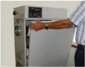 |
| 3.Pulloutthcfiltercartridge. | 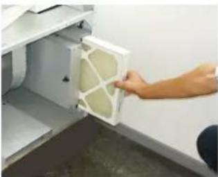 |
| 4.Cleanthefilterhousing. | |
| 5.Putinanewfilter.Followthcarrowtogetthecorrect airflowdirection. | 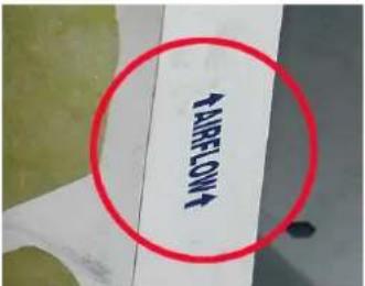 |
| 6.Liftthepanelinplace.Makesurethetwobottom hooksfitintothepanel. | 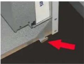 |
| 7.Tightenthetwotopscrews. |
8Faulttracing
8.1 General
The purpose of this chapter is to provide guidance in basic fault tracing and provide instructions for corrective action to remedy any faults. Go through the dissection 8.3, Fault tracing is before contacting Munters. The list provides help identifying types of fault that are easy to remedy without the assistance of specially trained personnel.
8.2 Safety

WARNING! ARNING!
Installation, adjustments, maintenance and repairs must only be carried out by qualified personnel who are aware of other risks involved when working with the equipment operating with high electrical voltage and high machine temperatures.

WARNING! ARNING!
Before doing any service or maintenance work on the unit makes sure that all electrical equipment is disconnected from the powers supply, and secured against treconnection.
8.3 Faulttracinglist
The control panel LED are the primary source of information for fault tracing when the unithas given an alarm stopped automatically.
GothroughthefaulttracinglistbelowbeforecontactingMuntersservicedepartment. Thelistcontains informationforidentifyingfaultsthatareeasytorepairwithoutthehelpofatechnician.
If the unit is equipped with the humidity regulation system RH98, see also appendix
1.6, Humidity control system.
| SymptomIndicatorsPossible becauseCorrectiveaction | |||
| Unithas stopped. | Nolights. | Powersupplyfailure.Checkpowersupplytotheunit. | |
| Mainssupplyswitch(no.1)issetto "0". | Setthemainssupplyswitchto"1"andcheckthatthemains connectionindicator(no.14)ison. | ||
| TransformerTC25fuseFU26 failure. | Investigatethecauseofthefaultandrectify.Replaceethefuse. | ||
| CircuitbreakerQM25trippeddue toawiringfault. | Investigatethecauseofthefault,andrectify.ResetQM25.Ifthefaultre-occurs,contactMunters. | ||
| stopped. | No.12 doesnot flash. | Theunithasbeensetto AUTomaticmodebymistakewith nohumiditysensorconnected. | SetthemodeswitchtoMANual,andcheckthattheunitstarts. Unithas |
| Humiditysensorfault(AUTomatic mode). | SetthemodeswitchtoMANual,andcheckthattheunitstarts.Ifthe unitstarts,thefaultisprobablyinthehumiditysensor.SetthemodeswitchtoAUTomaticmode,andcheckthehumidity sensorbyseeingifthedehumidifierstartswhenthehumiditysensor setpointisreduced.Thenresetthehumiditysensorsetpoint.Calibratethehumiditysensor(accordingtothemanufacturer's recommendations)ifnecessary,orreplaceit. | ||
| Unithas stopped. | No.12,6 and7are flashing. | Ifbothindicatorsareflashing, itindicatesthatone(orboth)of thehighttemperaturecut-outs (BT27andBT30)havetripped, duetoeitheranobstructioninthe reactivationairflow,orbecause thereactivationairflowhasbeenset toolow. | Switchoffthemainssupplyandallowtheunittocooldown.ResetQM12andQM14circuitbreakersasrequired.Checkthattheairinlet,outleductsandfiltersarefreefrom obstructionsandarenotblockedwithdirt.Switchonthemainssupplyatthemainssupplyswitchtoresetthe faultwarning.Checkandadjustthereactivationairflow,seesection 5.3,Airflowcheckandadjustment. |
| Unithas stopped. | Either No.12,6 and7are flashing. | Safetydeviceshavetrippeddueto aheaterelementorwiringfault. | Switchoffthemainssupplyandallowtheunittocooldown. |
| Investigatethecauseofthefault,andrectify. | |||
| ResetQM12andQM14asrequired. | |||
| Switchonthemainssupplyatthemainssupplyswitchtoresetthe faultwarning. | |||
| Unithas stopped. | No.12,2,8 and/or9are flashing. | Safetydevicehasstrippeddueto oneofthefollowing: | Switchoffthemainssupplyandallowtheunittocooldown. |
| FanmotorfaultInvestigatethecauseofthefault,andrectify. | |||
| DrivemotorfaultML420:ResetQM16- | drivemotor,reactivationfanandprocessfan.ML690-MLT1400:ResetQM16-reactivationfan.ResetQM21-drivemotororprocessfan.ResetQM18forunitswitha condenser. | ||
| RotorstopwarningInvestigatethecauseofthe"rotorstopped"warningandrectifythe fault. | |||
| WiringfaultSwitchonthemainssupply | atthemainssupplyswitch,andstartthe unittoresetthefaultwarning.Ifthefaultreoccurs,contactMunters. | ||
| Unithas stopped. | No.11and 12. | Unitsfittedwithanair-cooled condenser:Safetydeviceshavetrippeddueto acondenserfanfault. | Switchoffthemainssupplyandallowtheunittocooldown.Investigate thecauseofthefault,andrectify.ResetQM21. |
| OnlyNo. 12. | Safetydeviceshavetripped duetoacondenserheaterfault (reactivationairtemperature) | Investigatethecauseofthefault,andrectify.ResetQM23. | |
| Lossof performance: | Temperatureincreaseacrossthe reactivationbatteryistoolow. | Checkthefunctionofthereactivationheater. | |
| Dehumidifier appearsto beoperating correctly, butisnot controlling thehumidity | Reactivationandprocessairflows donotcorrespondtotherated airflows. | Checkandadjustthereactivationairflow,seesection5.3,Airflowcheckandadjustment. | |
| Rotordrivefailure.Checkrotordrivebeltanddrivemotor. | |||
| Incorrectfunctioningofhumidity sensor,RH98orVariDry(AUTomaticmode). | Checktheoperationandconnectionofthehumiditysensor,RH98or VariDryinaccordancewiththemanufacturer'srecommendations. | ||
Table8.1 Faulttracinglist
9Technicalspecification
9.1 Dimensionsandservicespace
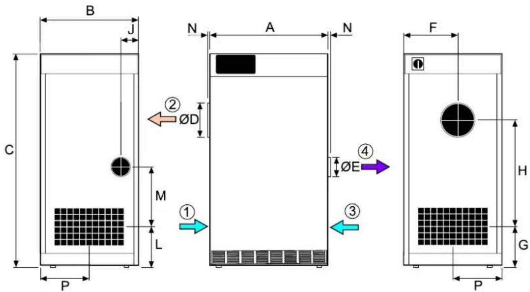
text_image
B J C M L P N A N ② ØD ① ØE ④ ③ F H G P- Processairinlet3. Reactivationairinlet
- Dryairoutlet4. Wetairoutlet
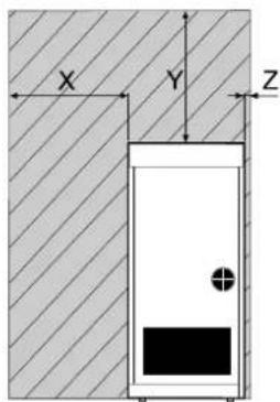
text_image
X Y Z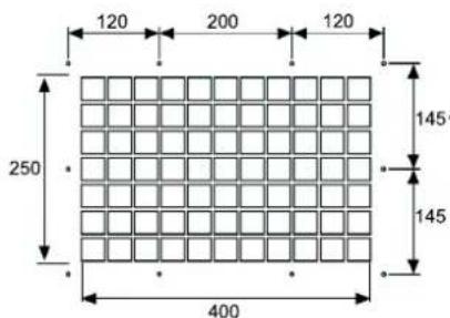
text_image
120 200 120 250 400 145 145Figure9.1 Required servicespace figure9.2 Hole pattern for duct connection
L J H G
| ModelFDCB A | Dimensions(mm) | Weight(kg) | |||||||||||||||
| A | (1) | Y(1) | Z(1) | ||||||||||||||
| ML45.20.13 | |||||||||||||||||
| ML65.20.12 | |||||||||||||||||
| MLT85.20.13 | |||||||||||||||||
| ML115.20.13 | |||||||||||||||||
| ML135.20.12 | |||||||||||||||||
| MLT145.20.12 | |||||||||||||||||
| (1)Spaceforservice. | |||||||||||||||||
Table9.1 Dimensions and services pacerequirements
9.2Capacitydiagrams
Approximate capacityinkg/h.PleasecontactyournearestMuntersofficeformoredetailedinformation.
NOTE! The below figures are based on a rated airflow.
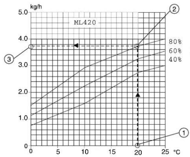
line
| Temperature (°C) | Yield (kg/h) - Curve 1 | Yield (kg/h) - Curve 2 | Yield (kg/h) - Curve 3 | | ---------------- | ---------------------- | ---------------------- | ---------------------- | | 0 | ~0.8 | ~1.5 | ~3.8 | | 20 | ~0.0 | ~3.8 | ~3.8 | | 25 | ~0.0 | ~5.0 | ~3.8 |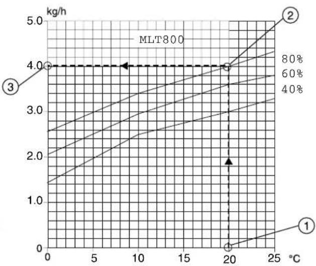
line
| Temperature (°C) | Yield (kg/h) - Curve 1 | Yield (kg/h) - Curve 2 | Yield (kg/h) - Curve 3 | Yield (kg/h) - Curve 40% | | ---------------- | ---------------------- | ---------------------- | ---------------------- | ----------------------- | | 0 | 1.5 | 4.0 | 4.0 | 4.0 | | 20 | 0.0 | 4.0 | 4.0 | 4.0 |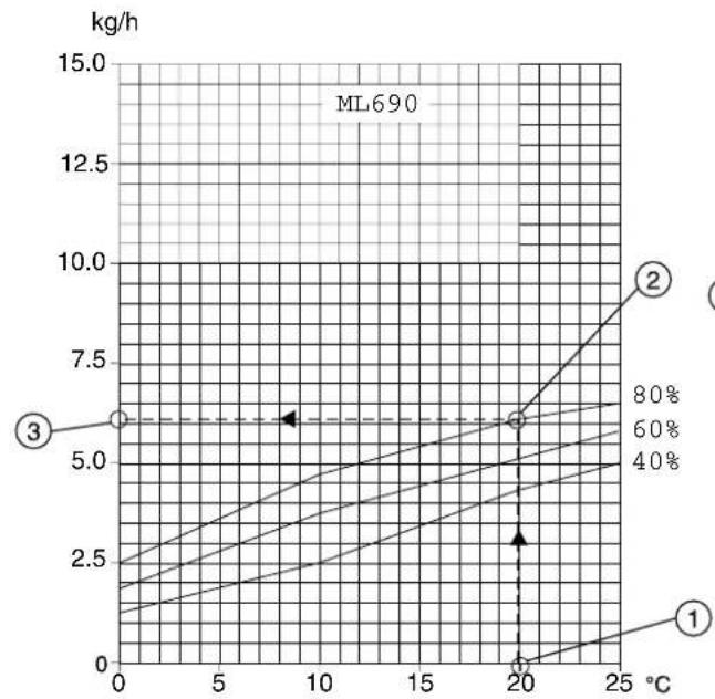
line
| Temperature (°C) | Yield (kg/h) - Curve 1 | Yield (kg/h) - Curve 2 | Yield (kg/h) - Curve 3 | | ---------------- | ---------------------- | ---------------------- | ---------------------- | | 0 | ~1.0 | ~2.5 | ~6.0 | | 20 | ~5.0 | ~6.0 | ~6.0 | | 25 | ~7.5 | ~15.0 | ~6.0 |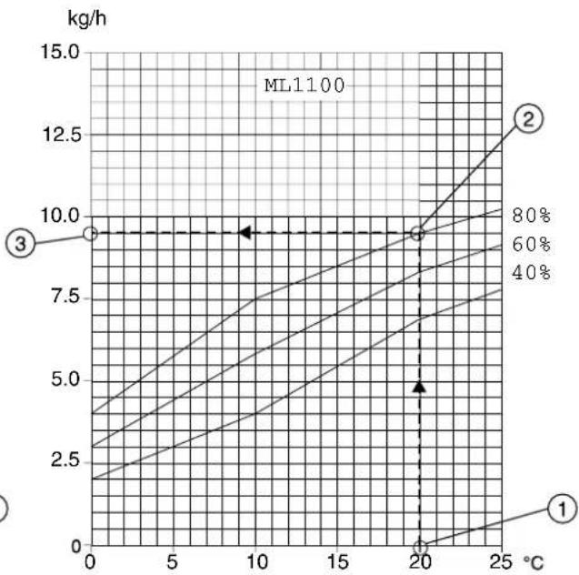
line
| Temperature (°C) | Yield (kg/h) - Curve 1 | Yield (kg/h) - Curve 2 | Yield (kg/h) - Curve 3 | | ---------------- | ---------------------- | ---------------------- | ---------------------- | | 0 | ~2.5 | ~9.0 | ~9.0 | | 20 | ~9.0 | ~9.0 | ~9.0 | | 25 | ~9.0 | ~12.5 | ~9.0 |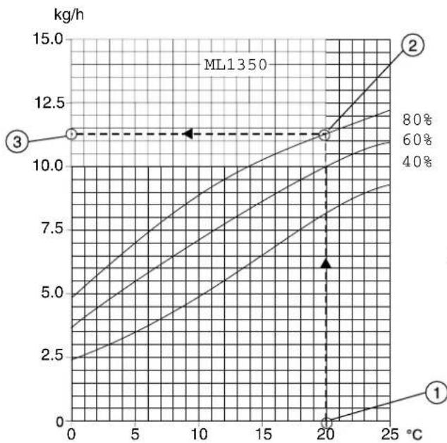
line
| Temperature (°C) | Yield (kg/h) - Curve 1 | Yield (kg/h) - Curve 2 | Yield (kg/h) - Curve 3 | | ---------------- | ---------------------- | ---------------------- | ---------------------- | | 0 | 2.5 | 5.0 | 11.5 | | 20 | 9.0 | 11.5 | 11.5 | | 25 | 9.5 | 14.0 | 11.5 |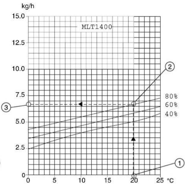
line
| Temperature (°C) | Curve 1 (kg/h) | Curve 2 (kg/h) | Curve 3 (kg/h) | | ---------------- | -------------- | -------------- | -------------- | | 0 | ~2.5 | ~4.0 | 7.5 | | 20 | ~6.0 | ~7.5 | 7.5 | | 25 | ~8.0 | ~10.0 | 7.5 |1Processairtemperature(°C)
2Processairrelativehumidity(%RH)
3Dehumidificationcapacity(moistureremovalperhour)(kg/h)
9.3 Technicaldata
The following is applicable to units fitted with the electric reactivation heater.
| ModelML420ML690MLT800ML1100ML1350MLT1400 | |||||||
| Processair(1) | |||||||
| Ratedairflow(m 3/s)0,1160,1920,2220,3050,3750,388 | |||||||
| Ratedairflow(m 3/h) | |||||||
| Minimumavailablestaticpressure(Pa) (300 200 300) 200 | |||||||
| Fanmotorpower(kW)at50Hz1,13) 1,1 1,1 0,550,550,37 | |||||||
| Fanmotorpower(kW)at60Hz (3)1,321,321,320,660,560,37 | |||||||
| Reactivationair(1) | |||||||
| Ratedairflow(m 3/s)0,0430,0710,0430,1130,1360,071 | |||||||
| Ratedairflow(m 3/h) | |||||||
| 30min20min20mable20ticpressure(Pa) | |||||||
| Fanmotorpower(kW)at50Hz1,87 0,550,550,370,37 | - | ||||||
| Fanmotorpower(kW)at60Hz1,4 0,650,660,440,44 | - | ||||||
| Ratedcurrent | |||||||
| Current(25p5/phase)3~50Hz200V | |||||||
| Current(25p5/phase)3~60Hz200V | |||||||
| Current(22hps/phase)3~50Hz220V | |||||||
| 36,416(22hps/phase)3~60Hz220V | |||||||
| 35,416(21hps/phase)3~50Hz230V | |||||||
| Current(27hps/phase)3~50Hz380V | |||||||
| 9Current(amps/phase)3~60Hz380V | |||||||
| 5Current(amps/phase)3~50Hz400V | |||||||
| Current(22hps/phase)3~50Hz415V | |||||||
| Current(22hps/phase)3~60Hz440V | |||||||
| 6Current(amps/phase)3~60Hz460V | |||||||
| Current(27hps/phase)3~60Hz480V | |||||||
| Reactivationheater | |||||||
| Temperature increase grossheater(°C) | |||||||
| Reactivationheaterpower(kW) | |||||||
| Miscellaneousdata | |||||||
| Drivemotorpower(W) | |||||||
| Filters | |||||||
| IECprotectionclass(unit) | |||||||
| IECprotectionClass(electricalpanel) | |||||||
| FanmotorQinstfinsulationclass | |||||||
| DrivemotorQinstfinsulationclass | |||||||
| High Temperaturecut-out(°C) | |||||||
| 220/240nercontrollersupplyvoltage1~50Hz(VAC) | |||||||
| 240ncontorcoilvoltage(VAC) | |||||||
| External(potential-free)outputcontacts4 | 2A,50VAC(max.) |
| Corrosionclass,outsidecasingC4(painted,AluZink150,ISO12944) | |
| Corrosionclass,insidecasingC3(unpainted,AluZink150,ISO12944) | |
| Environmentalconditions | |
| Operatingtemperature(°C) | -20...+40 |
| Maximuminstallationalaltitude,abovesealevel(m) | 2000 |
| Transportandstoragetemperature(°C) | -20...+70 |
| (1)Figuresquotedarebasedonfaninlettemperatureof20°C,andanairdensityof1,2kg/m3.(2)WithoutoptionalF5orF7filterboxes.(3)ML420dehumidifiershaveasinglemotordrivingbothprocessairandreactivationairfans.(4)ContactsonthePCBusedtogiveanexternalindicationtotheunit(output). | |
Table9.2 Technicaldata
9.4Sounddata
text_image
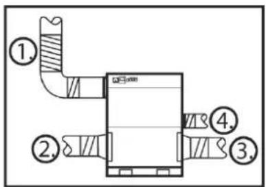
Technical diagram of a ventilation system with numbered components and labeled partsFigure9.3Ductconnections
1.Ductworkfordryair
2.Ductworkforprocessair
- Ductwork for reactivation air
4.Ductworkforwetair
Definitions:
Lp(A)=Soundpressure(freefield,DirectivityfactorQ=2,d=1distancefromsourceinmeter) Lp(A)=Lw(A)+10Log(Q/(4 d^2)) Lw(A)=SoundpowerleveldB(A-weighted)
9.4.1 SounddataML420
| Lp(A)at1mLw(A) | Measurerange(Hz) | |||||||||
| dBdB63125 | 280 | 000000 | ||||||||
| 58 | ||||||||||
Table9.3 Soundtoroom, allinlets and outlets ducted
| Lw(AT)Measurerange(Hz) | dB6312528060000000000000000000000000000000000000000000000000000000000000000000000000000000000000000000000000000 | ||||||||
| 1Dryair | |||||||||
| 2Processair | |||||||||
| 3Reactair | |||||||||
| 4Wetair | |||||||||
Table9.4 Soundinducts
9.4.2 SounddataML690
| Lp(A)at1mLw(A) | Measurerange(Hz) | |||||||||
| dBdB63125 | 250500100 | 020004 | 0008000 | |||||||
| 60 | ||||||||||
Table9.5 Soundtoroom, allinlets and outlets ducted
| Lw(A)Measurerange(Hz) | dB631252505001000200040008000 | ||||||||
| 69 | 1Dryair | ||||||||
| 3 91 | 2Processair | ||||||||
| 93 76 | 3Reactair | ||||||||
| 71 | 4Wetair | ||||||||
Table9.6 Soundinducts
9.4.3 SounddataMLT800
| Lp(A)at1mLw(A) | Measurerange(Hz) | |||||||||
| dBdB63125 | 250500100 | 020004 | 0008000 | |||||||
| 59 | ||||||||||
Table9.7 Soundtoroom, allinletsandoutletsducted
| Lw(A)Meatsurerange(Hz) | ||||||||||
| dB631252505001000200040008000 | ||||||||||
| 6 | 71 | 1Dryair | ||||||||
| 2Processair | ||||||||||
| 93 | 76 | 3Reactair | ||||||||
| 4Wetair | ||||||||||
Table9.8 Soundinducts
9.4.4 SounddataML1100
| Lp(A)at1mLw(A) | Measurerange(Hz) | |||||||||
| dBdB63125 | 250500100 | 020004 | 0008000 | |||||||
| 64 | ||||||||||
Table9.9 Soundtoroom, allinlets and outlets ducted
| Lw(A)Measurerange(Hz) | dB631252505001000200040008000 | ||||||||
| 7 89 | 1Dryair | ||||||||
| 2Processair | |||||||||
| 93 84 | 3Reactair | ||||||||
| 4Wetair | |||||||||
Table9.10 Soundinducts
| 9.4.5SounddataML1350 | |||||||||||
| Lp(A)at1mLw(A) | Measurerange(Hz) | ||||||||||
| dBdB63125 | 2505001000 | 20004 | 0008000 | ||||||||
| 67 | |||||||||||
Table9.11 Soundtoroom, allinlets and outlets ducted
| Lw(A)Meatsurerange(Hz) | ||||||||||
| dB631252505001000200040008000 | ||||||||||
| 6 | 80 | 1Dryair | ||||||||
| 2Processair | ||||||||||
| 93 | 83 | 3Reactair | ||||||||
| 4Wetair | ||||||||||
Table9.12 Soundinducts
9.4.6 Sounddata MLT1400
| Lp(A)at1mLw(A) | Measurerange(Hz) | |||||||||
| dBdB63125 | 2505001000 | 020004 | 0008000 | |||||||
| 63 | ||||||||||
Table9.13 Soundtoroom, allinlets and outlets ducted
| Lw(A)Measurerange(Hz) | dB631252505001000200040008000 | ||||||||
| 1Dryair | |||||||||
| 2Processair | |||||||||
| 3Reactair | |||||||||
| 4Wetair | |||||||||
Table9.14 Soundinducts
10Scrapping
The unit must be scrapped in accordance with applicable legal requirements and regulations. Contact your local authorities.
Iftherotororfiltershavebeenexposedtochemicalsthataredangeroustotheenvironmenttheriskmust beassessed.Thechemicalscanaccumulateinthematerial.Takethenecessaryprecautionstocomplywith applicablelocallegalrequirementsandregulations.
Therotormaterialisnotcombustible, and should be deposited like glass fibrematerials.

WARNING! ARNING!
Iftherotoristobecutinpieces, wearasuitableCEmarkedfacemaskselectedandfittedinaccordancewiththe applicablesafetystandardstoprotectfromthedust.
Appendix1Options
1.1 General
TheML-seriesdehumidifiersaredesignedsothatoptionalproductscanbeeasilyfittedtothem.
Thisappendixcontainsinformationaboutalloptionalconfigurationsandcomponentsthatcanbeadded whenorderingMLdehumidifiers.
NOTE! Voltagedropscanoccurwhenusingexcessivelylongcables. If there is less than 20 V supply at the connection point so of the humidity sensor (onthedehumidifier), a separate relay controlled by the humidity sensor must be used.
1.2 Runningtimemeter
Therunningtimemeterrecordsthetotalnumberofhoursthedehumidifierhasrun. Thelasttwodigits representapercentagepartofanhour. Therunningtimemetercannotbereset.
Example:0000475representsfourhoursand45minutes.
1.3 Rotorstopalarm
Anoptionalreedswitchmomentarilysendsapulseonceperrevolutionoftherotor,i.e.oncevery8 minutes.Theswitchisactivatedbyamagnetmountedontherotortoproducca0VDCpulse.
If the pulsedoes not occur within 10 minutes, the drivemotor and fault warning indicators flash to show that afault has occurred. The unit is automatically switched off.
1.4Blockedfilteralarm
Adifferential pressures switch can be fitted to the process air and reactivation air filters. When the pressure differential acrossthe filter exceeds the below preset value, these switch closes, which sends a message (blocked filter) to the PCB card. The process air or reactivation air filter indicator lights up to indicate the specific blocked filter.
1.5Filterbox-M5andF7
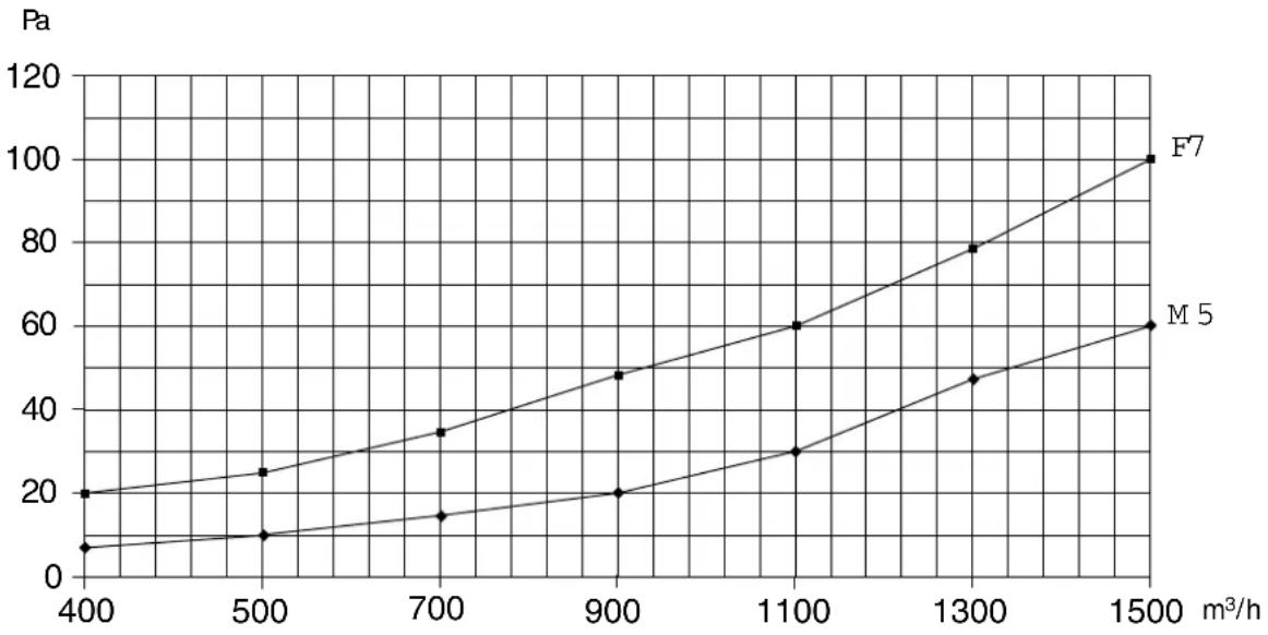
ML420-MLT1400dehumidifierscanbeequippedwithexternalfilterboxesM5orF7.
For instructions on how to attach the filter box to the process air inlet or reactivation air inlet, referto the instruction supplied with the delivery of the filter box.
Thediagrambelowshowsthepressuredrop(Pa)acrossthefilterinthefilterbox.
line
| m³/h | F7 | M 5 | |------|------|------| | 400 | 20 | 8 | | 500 | 25 | 10 | | 700 | 35 | 15 | | 900 | 48 | 20 | | 1100 | 60 | 30 | | 1300 | 78 | 48 | | 1500 | 100 | 60 |Figure1.1 Pressuredrop, filterin the filterbox
NOTE! The pressured drop for the reactivations side is not shown on the diagrams since the values are so small that they donot affect the performance of the unit.
1.6 Humidity control system
1.6.1 Introduction
MuntersRH98 and Vari Dry are humidity control systems intended for use with Munters de humidifiers. They control the air humidity by regulating the power to the unit reactivation heater.
Thesystemcomprisesahumiditytransmitterandacontrolunit. The humidity transmitter is atruetwo wire transmitter, which is positioned where the air humidity is to be controlled, either in the relevant room or in the air duct.
The control units sends control signal to the dehumidifier. The power control is performed in one or two steps.
Thesystemhasapotentialfreecontacttowhichanexternalalarmdevicecanbeconnected.
1.6.2 Transmitter
The humidity transmitters are available into different types, wall or duct mounted.
The humidity transmitters sensoremits a signal proportional to the air humidity.
Thesignalisamplifiedandsenttothecontrolunitbycable.
The humidity transmitters sensorissensitive and must be handled with care.
1.6.3 Controlunit
The control unit contains a controller, which receives the signal from the humidity transmitter. The controller thensends a controlsignal to the dehumidifier which determines the activation heater output.
Thereisalsoanoperatorpanelwithadisplayonthecontrolunit.Duringnormaloperation,thedisplay showsthecurrentmeasuredairhumidity.
Differentparameterscanbesetusingthepushbuttonsonthepanel.Examplesaresettingsforairhumidity, controllerlimitsandalarmlimits.
The control unit constantly receives a signal from the humidity transmitter, and control the air humidity by regulating the power to the unit reactivation heater in one cortow steps. In the event of two heater steps, abasic step 2/3 of thereactivation output is achieved, after which 1/3 of thereactivation output can be controlled as following step.
The control unit is provided with a potential free contact to which an external alarm device can be connected. The external alarm is activated together with the internal alarm.
1.6.4 Setpointsandcontrolparameters
Checkingandchangingsetpointsandcontrolparameterscanbemadeduringoperationorinstand-bymode.
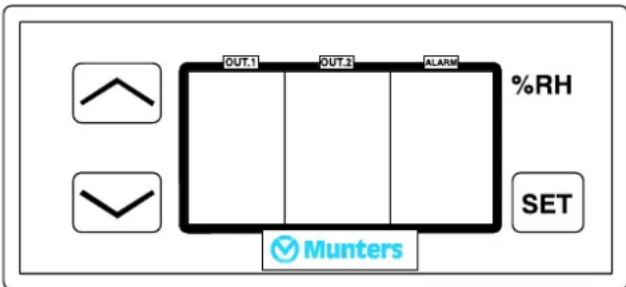
text_image
OUT1 OUT2 ALARM %RH SET MuntersFigure1.2Operatorpanel
| ButtonFunction | |
| Display/changeacertainvalueandresetthealarm | |
 | Increasethevalue |
 | Decreasethevalue |
| %RH:Displaypositionofcontrolstepsforreactivationheater(0=off;1=on). |
During normal operation and in any position of the modes switch the current relative air humidity is displayed.

CAUTION! UTION!
Damageduetoincorrectadjustmentofthesystemmayinvalidatethewarranty.
1.6.5 Display/changesetpointforrelativehumidity
- Press/release.Thevalueinthelowerrightcornerstartsflashingandshowsthecurrentsetpoint.The displayautomaticallyreturnstonormalafterabouttwentyseconds,i.e.showscurrentvalueforrelative humidity.
- Pressandholddownandthecurrentsetpointlightsupwithafixedlight. When the button is released again, the display flashes before automatically returning to normal.
- Pressandholddownandatthesametimepress ortosetthedesiredsetpoint.
- Release and the display start to flash, indicating the new setting before it automatically return to normal i.e. show the current air humidity.
1.6.6 Display/changeotherparameters
Theoperatorpanelsetpointsarepresetatthefactoryto50%RH. Severalotherinternalparameterscanbe setinadditionothcsetpointe.gdifferential,sensoroffsetandsetpointrange,seeTable1.1.
-
Pressandholddown √ formorethantensecondstoshowtheparametermenu. The charactersinthe topandbottomsegmentsintheleft-handdisplaystarttoflash.Parameter10isshown.Release.
-
Pressortoselectaparameter.
-
Pressandholdtoshowthecurrentvaluefortheselectedparameter.
-
Pressandholdandpress √ ortochangetheparametervalue.
-
Release. Thenewsettingsaresavedautomatically. Thedisplayautomaticallyreturnstonormalafter abouttwentyseconds, i.e. showscurrentvalueforrelativehumidity.
| Parameter | DescriptionPossibleparameterselectionDefaultsetting | ||
| 05Correctionofthehumiditytransmitter'sread-offvalue0%RHNosettings | |||
| 10OFF/ONinterval,stage11-15%RH2%RH11Offsetstage1-15-+15%RH-1%RH12OFF/ONinterval,stage21-15%RH6%RH13Offsetstage2-15-+15%RH-1%RH | (1)(2) | ||
| 14OFF/RH19/Rvalalarmoutput15Offset15+15%RH2%Rhoutput | |||
| 0=Notactivated32Absolutethresholdtype:-50%RH-100-+30%Rhumalarmthreshold10%RH-100-820%Rhumalarmthreshold33Delayforminimumalarm0-99minutes0min. 0-99min34Delayformaximumalarm0=monitorof35Functioncheckalarmoutput36ResetalarmwhenthecauseofthealarmisReefitedYes37AlarmresettingwhentheSETbuttonhptsYes(displayonly) | 2=Relative | ||
| 0min. 40BeforedelayafterpowerfailureForcedelayfunctionalhumiditytransmitoffdBhumidification; | 2=Dehumidification | ||
| (1)ActivatedwhenRHexceeds2%ofthesetpoint,deactivatedwhenRHfallsbelow1%ofthesetpoint.(2)ActivatedwhenRHexceeds6%ofthesetpoint,deactivatedwhenRHfallsbelow1%ofthesetpoint. | |||
| 01Proportionalband1-15%RH5 | |||
| 02Integrationtime0-99seconds0(=off) | |||
| 03Differentialaction,percentage0-100%RH0(=off) | |||
| 04Cycletime0-999seconds20 | |||
| 05Correctionofthehumiditysknsetsisvalue-15-+15%RH | |||
| 10Offset,relay-2 | |||
| Differential,relay-2 | |||
| 20Minimumsetpoint | |||
| 21Maximumsetpoint | |||
| 40Delayinregainingsupply26finapowercut | |||
| 41Forcedsolid-stateoutputwOeNesd=100dattutput | |||
| 42Foredrelay-2outpOeWreflesensorfault | |||
Table1.1 Operatorpanelsystemparameters—RH98
Table1.2 Operatorpanelsystemparameters—VariDry
1.6.7 Processalarms
Theoperatorpanelisequippedwithaninternalalarmthatisactivatedwhenthealarmthresholdsare exceeded.Thealarmisindicatedinthedisplayontheoperatorpanel.
Alarmmessages
Thedisplayontheoperatorpanelshowsthefollowingmessages(steadilylit):
rHI Upperalarmlimitexceeded
rLO Loweralarmlimitexceeded
E1 Faultyhumiditytransmitterorincorrectconnections
EEE Allparametersettingsarelost
AcknowledgealarmonRH98
Acknowledgethealarmbypressingontheoperatorpanel. Thedisplaynowstartstoflashanddisplays thealarmmessageandthecurrentrelativeairhumidityalternately. Thefunctionfortheresetbuttonis dependentontheparametersettings,seeTable1.1.
Sensorcalibration
The humidity transmitter's readoff value can be calibrated using the operator panels sensor offset, parameter 05, Table 1.1.
Example: If 3% RHistoomuch, the offset should be reduced by 3%.
ContactMuntersforcalibrationofthehumiditytransmitter.
2ContactMunters
| AUSTRIA | MuntersGmbHAirTreatmentZweigniederlassungWien | Eduard-Kittenberger-Gasse56, Obj.6A-1235Wien | Tel:+4316164298-9251luftentfeuchtung@munters.atwww.munters.at |
| BELGIUM | MuntersBelgiumnvAirTreatment | Blarenberglaan21cB-2800Mechelen | Tel:+3215285611service@muntersbelgium.bewww.muntersbelgium.be |
| CZECHREPUBLIC | MuntersCZ,organizacnislozkaAirTreatment | Slevacska2368/68CZ-61500BRNO | Tel:+420775569657info@munters-odvlhcovani.czwww.munters-odvlhcovani.cz |
| DENMARK | MuntersA/SAirTreatment | Ryttermarken4DK-3520Farum | Tel:+4544953355info@munters.dkwww.munters.dk |
| FINLAND | MuntersFinlandOyKuivaajamyynti | Hakamäenkuja3FI-01510VANTAA | Tel:+358207768230laitemyynti@munters.fiwww.munters.fi |
| FRANCE | MuntersFranceSASAirTreatment | 106,BoulevardHéloiseF-95815ArgenteuilCedex | Tel:+33134115757dh@munters.frwww.munters.fr |
| GERMANY | MuntersGmbHAirTreatment-Zentrale | Hans-Duncker-Str.8D-21035Hamburg | Tel:+49(0)40879690-0mgd@munters.dewww.munters.de |
| ITALY | MuntersItalyS.p.AAirTreatment | StradaPiani2I-18027ChiusavecchiaIM | Tel:+390183521377marketing@munters.itwww.munters.it |
| NETHERLANDS | MuntersVochtbeheersingEnergieweg69 | NL-2404HEAlphena/dRijn | Tel:+31172433231vochtbeheersing@munters.nlwww.munters.nl |
| POLAND | MuntersSp.zo.o.OddzialwPolsceAirTreatment | ul.Swietojanska55/1181-391Gdynia | Tel.:+48583053517dh@munters.plwww.munters.com.pl |
| SPAIN | MuntersSpainSAAirTreatment | EuropaEpresarial.EdificioLondres.C/PlayadeLlenres2.28230LasMatas.Madrid | Tel:+34916400902marketing@munters.eswww.munters.es |
| SWEDEN | MuntersEuropeABAirTreatment | P_O.Box1150SE-16426Kista | Tel:+4686266300avfuktning@munters.sewww.munters.se |
| SWITZERLAND | MuntersGmbHAirTreatmentZweigniederlassungRümlang | Glattalstr.501CH-8153Rümlang | Tel:+41523438886info.dh@munters.chwww.munters.ch |
| UNITEDKINGDOM | MuntersLtdAirTreatment | KnowledgeCentre,WybostonLakesGreatNorthRoad,WybostonBedfordshireMK443BY | Tel:+441480432243info@munters.co.ukwww.munters.co.uk |
| AUSTRALIA | Tel:+61288431588dh.info@munters.com.au | MEXICO | Tel:+527222704029munters@munters.com.mx |
| BRAZIL | Tel:+551150540150www.munters.com.br | SINGAPORE | Tel:+6567446828singapore@muntersasia.com |
| CANADA | Tel:+1-800-843-5360dhinfo@munters.com | SOUTHAFRICA | Tel:+27119972000info@munters.co.za |
| CHINA | Tel:+861080418000marketing@munters.cn | TURKEY | Tel:+902165481444info@muntersform.com |
| INDIA | Tel:+912066818900info@munters.in | UAE(Dubai) | Tel:+97148813026middle.east@munters.com |
| JAPAN | Tel:+81359700021mkk@munters.jp | USA | Tel:+1-800-843-5360dhinfo@munters.com |
| KOREA | Tel:+8227618701munters@munters.kr |
www.munters.com