
MK6025GAS - Festplatte TOSHIBA - Kostenlose Bedienungsanleitung
Finden Sie kostenlos die Bedienungsanleitung des Geräts MK6025GAS TOSHIBA als PDF.

| Produkttyp | Festplatte |
| Marke | Toshiba |
| Modell | MK6025GAS |
| Kapazität | 60 GB |
| Formfaktor | 2,5 Zoll |
| Höhe | 9,5 mm |
| Schnittstelle | ATA-2/3/4/5/6 |
| Host-Übertragungsrate | 100 MB/s |
| Puffergröße | 8 MB |
| Drehzahl | 4.200 U/min |
| Mittlere Suchzeit | 12 ms |
| Mittlere Zugriffszeit | 7,14 ms |
| Anzahl der Platten | 2 |
| Anzahl der Schreib-/Leseköpfe | 4 |
| Spannung | 5 V ±5% |
| Stromverbrauch (Start) | 4,7 W typ. |
| Stromverbrauch (Lesen/Schreiben) | 2,3 W typ. |
| Stromverbrauch (Schlaf) | 0,1 W typ. |
| Gewicht | 98 g typ. |
| Abmessungen (B x T x H) | 69,85 mm x 100 mm x 9,5 mm |
| Betriebsschock | 200 G (2 ms) |
| Nichtbetriebsschock | 800 G (1 ms) |
| MTBF | 300.000 Stunden |
| Zertifikate | UL 1950, CSA C22.2, TUV, EMC |
Häufig gestellte Fragen - MK6025GAS TOSHIBA
Benutzerfragen zu MK6025GAS TOSHIBA
0 Frage zu diesem Gerät. Beantworten Sie die, die Sie kennen, oder stellen Sie Ihre eigene.
Eine neue Frage zu diesem Gerät stellen
Laden Sie die Anleitung für Ihr Festplatte kostenlos im PDF-Format! Finden Sie Ihr Handbuch MK6025GAS - TOSHIBA und nehmen Sie Ihr elektronisches Gerät wieder in die Hand. Auf dieser Seite sind alle Dokumente veröffentlicht, die für die Verwendung Ihres Geräts notwendig sind. MK6025GAS von der Marke TOSHIBA.
BEDIENUNGSANLEITUNG MK6025GAS TOSHIBA
TOSHIBA AMERICA INFORMATION SYSTEMS STORAGE DEVICE DIVISION IRVINE, CALIFORNIA
MK6025GAS (HDD2189)
2.5-INCH HARD DISK DRIVE
USER MANUAL
TOSHIBA
CONTENTS
Introduction....1
Setup 2
Using the HDD ....4
Troubleshooting....5
Specifications ....6
Drive Connectors....8
INTRODUCTION – MK6025GAS (HDD2189)
General Features
- 2.5" sized drive
- 60 Gigabytes
- 9.5mm High
• 12ms Average Seek Time
• ATA-2,3,4,5,6 Interface
• Supports high transfer rates of 100 MB/sec - 8MB Buffer
• Rotational speed of 4,200rpm
• MTTF 300,000 Hours
SETUP - MK6025GAS (HDD2189)

Caution: Your Hard Disk Drive is a precision device and even a small drop onto any surface can cause damage. Electronstatic discharge can also damage the drive. You should ground yourself prior to handling the drive.
Master/Slave Settings
Your Toshiba Hard Disk Drive can be configured as either a "Master" or "Slave" unit. Master configuration is used for all single drive applications, and master or slave configuration (only one of each per port) is used for two drive applications. Use the information in the following table before setting drive as Master or Slave.
Master configuration is obtained by setting jumpers A, B, C & D open (no jumper present). Slave configuration is obtained by setting jumpers C-D. When B-D jumper is installed, the drive is configured as cable select. If pin 28 = Low, the drive is "Master", if pin 28 - High, the drive is "Slave".
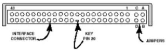
Figure 1.HDD Jumper Locations
| JUMPER P28 DRIVE | |
| No Jumper - Master Drive | |
| C-D Jumper - Slave Drive | |
| B-D Jumper LOW Master Drive | |
| B-D Jumper HIGH Slave Drive | |
| A-B Jumper - Slave Drive | |
| A-C Jumper - Prohibit |
Installation Notes
- The drive should be mounted carefully on the surface of 0.1mm or less flatness to avoid excessive distortion.
- In order to prevent short-circuit under any circumstances, a space of 0.5mm or more should be kept under the PCB.
- Space should be kept around the drive to avoid any contact with other parts, which may occur due to shock or vibration.
- The temperature of the top cover and the base must always be kept under 60C to maintain the required reliability.
- Be sure not to cover the breathing hole to keep the pressure inside the drive at a certain level
- Do not apply any force to the top cover, except the screw areas on top cover. Maximum force to the specified area is 2N.
- The drive contains several parts which may be easily damaged by ESD (Electric Static Discharge). Avoid touching the interface connector pins and the surface of PCB. Be sure to use ESD proof wrist strap when handling drive.
- The four mounting screws should be tightened equally with 0.3N-m (3kgf-cm) torque. The depth should be 3.0mm minimum and 3.5mm maximum.
Placing Hard Drive inside your Computer
- Determine mounting configuration (the drive can be mounted in either a horizontal or vertical orientation)
- Configure drive for system application.
- Configure the adapter board for the specific system application (if required).
• Install adapter board into an unused PC/AT 16 bit slot (if required). - Install the I/F cable to the system's 44 pin connector port or adapter board. Ensure pin 1 is oriented correctly, (pin 1 on the cable is usually identified by a red or blue strip.)
- Set correct drive type in system CMOS
• Refer to applicable manuals for software installation instructions.

Important Note: Disconnect power from your computer system before beginning installation.
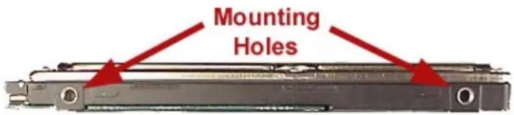
Figure 2.HDD Mounting Holes
USING THE HARD DISK DRIVE – MK6025GAS (HDD2189)
Backing up Data Files
To avoid data loss, regularly back up the data files on the hard disk drive.
TROUBLESHOOTING - MK6025GAS (HDD2189)
| Problem Solution | |
| My system is not able to recognize all available capacity on my Hard Disk Drive. What do I need to do to utilize the complete hard drive? | There are some systems that are unable to recognize the new larger Hard Drives on the market. 3rd party software is available that breaks the "capacity barrier". Some suggestions are EZ Drive by Micro House and Disk Manager DiskGo by Ontrack. Check with your local computer/software supplier for availability or contact the software manufacturer. |
| How do I install my 2.5" Toshiba Hard Drive into my desktop or tower system? | You will need a HDD mounting kit in order to install a Toshiba 2.5" drive into your desktop or tower system. Contact your local computer supplier for kit availability. |
SPECIFICATIONS -MK6025GAS (HDD2189)
General
Model
MK6025GAS
(HDD2189)
Interface
ATA-2/3/4/5/6
Functionality
Formatted Capacity 60.011GB
Rotational Speed 4200rpm
Avg. Rotational Latency 7.14/ms
Spin-up Time 4sec (typical)
Buffer
8MB
Seek Time (Average) 12
Internal Transfer Rate 201.6 \~ 307.5 Mbits/sec (max)
Host Transfer Rate 100Mbytes/sec
Internal Drive Characteristics
Number of Disks 2
Number of Read/Write Heads 4
Track Density (TPI) 88.1k
User Data Cylinders 42,480
Logical Cylinders 16,383
Logical Heads 16
Logical Sectors/track 63
Bytes per Sector 512
Logical Blocks (LBA) 117,210,240
Reliability
Preventative maintenance None
1 error per 10^13 bits read
Nonrecoverable read errors
Electrical
Voltage
5V 5%
Power Consumption
Start
4.7W typ
Seek
2.6W typ
Read/Write
2.3W typ
Sleep
0.1W typ
Energy Consumption Efficiency
0.012W/GB avg
Shock
Operating
1,960m/s² (200G)(2msec)
Non-Operating
7,840m/s² (800G)(1msec)
Physical
Height
0.37" (9.5mm)
Width
2.75" (69.85mm)
Depth
3.94" (100mm)
Weight
3.46oz (98g) typ
Regulatory
The drive satisfies the following standards:
Underwriters Laboratories (UL) 1950
Canadian Standard Association (CSA) C22.2 No.220 No. 950
TUV Rheinland EN 60 950
EMC - EN50081-1 EN55022: 1988 Class B
EN60555-2: 1987+ A1
EN60555-3: 77A (Co) 38
EMC - EN50082-1 IEC 801-2: 1991
EIC 801-3: 1994
IEC 801-4: 1988
DRIVE CONNECTORS -MK6025GAS (HDD2189)
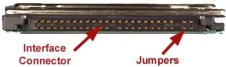
Figure 1.MK6025GAS HDD Rear View - Connectors
Interface Connector
Drive Side Connector Yamaichi GAP050K11617 or equivalent
Recommended Host Side Connector
Board Straight type: Berg 86455-044 86456-044 or equivalent
Cable Berg 89361-044 or equivalent
Recommended Cable Characteristics
Standard diameter 0.32mm (28AWG)
Characteristics impedance 100 - 132ohm
Max Length 0.46mm (max)
Capacitance
35pF
* cable is not included with drive
Interface Pin Assignment
| DRIVE INTERFACE SIGNALS | |||
| PIN | SIGNAL | PIN | SIGNAL |
| 1 RESET 2 GROUND | |||
| 3 DD 7 4 DD 8 | |||
| 5 DD 6 6 DD 9 | |||
| 7 DD 5 8 DD 10 | |||
| 9 DD 4 10 DD 11 | |||
| 11 DD 3 12 DD 12 | |||
| 13 DD 2 14 DD 13 | |||
| 15 DD 1 16 DD 14 | |||
| 17 DD 0 18 DD 15 | |||
| 19 | GROUND | 20 | KE |
| 21 | DMARQ | 22 | GROUND |
| 23 | DIOW/STOP | 24 | GROUND |
| 25 | DIOR/-DMARDY HSTROBE | 26 | GROUND |
| 27 | IORDY/-DMARDY/-DSTROBE | 28 | CSEL |
| 29 | DMACK | 30 | GROUND |
| 31 | INTRQ | 32 | IOCS16 |
| 33 | DA1 | 34 | PDIAG |
| 35 | DA0 | 36 | DA 2 |
| 37 | CS0 | 38 | CS1 |
| 39 | DASP | 40 | GROUND |
| 41 | +5V (LOGIC) | 42 | +5V (MOTOR) |
| 43 | GROUND | 44 | RESERVED |
| Note: Symbol () in front of signal indicates negative logic. | |||