
SM590I-II-WX - Lautsprecher SoundTube - Kostenlose Bedienungsanleitung
Finden Sie kostenlos die Bedienungsanleitung des Geräts SM590I-II-WX SoundTube als PDF.


Benutzerfragen zu SM590I-II-WX SoundTube
0 Frage zu diesem Gerät. Beantworten Sie die, die Sie kennen, oder stellen Sie Ihre eigene.
Eine neue Frage zu diesem Gerät stellen
Laden Sie die Anleitung für Ihr Lautsprecher kostenlos im PDF-Format! Finden Sie Ihr Handbuch SM590I-II-WX - SoundTube und nehmen Sie Ihr elektronisches Gerät wieder in die Hand. Auf dieser Seite sind alle Dokumente veröffentlicht, die für die Verwendung Ihres Geräts notwendig sind. SM590I-II-WX von der Marke SoundTube.
BEDIENUNGSANLEITUNG SM590I-II-WX SoundTube
SM5 Series
Install Instructions For:
SM500i-II, SM500i-II-WX, SM590i-II, SM590i-II-WX speaker
1.435.647.9555
800.647.TUBE
www.soundtube.com
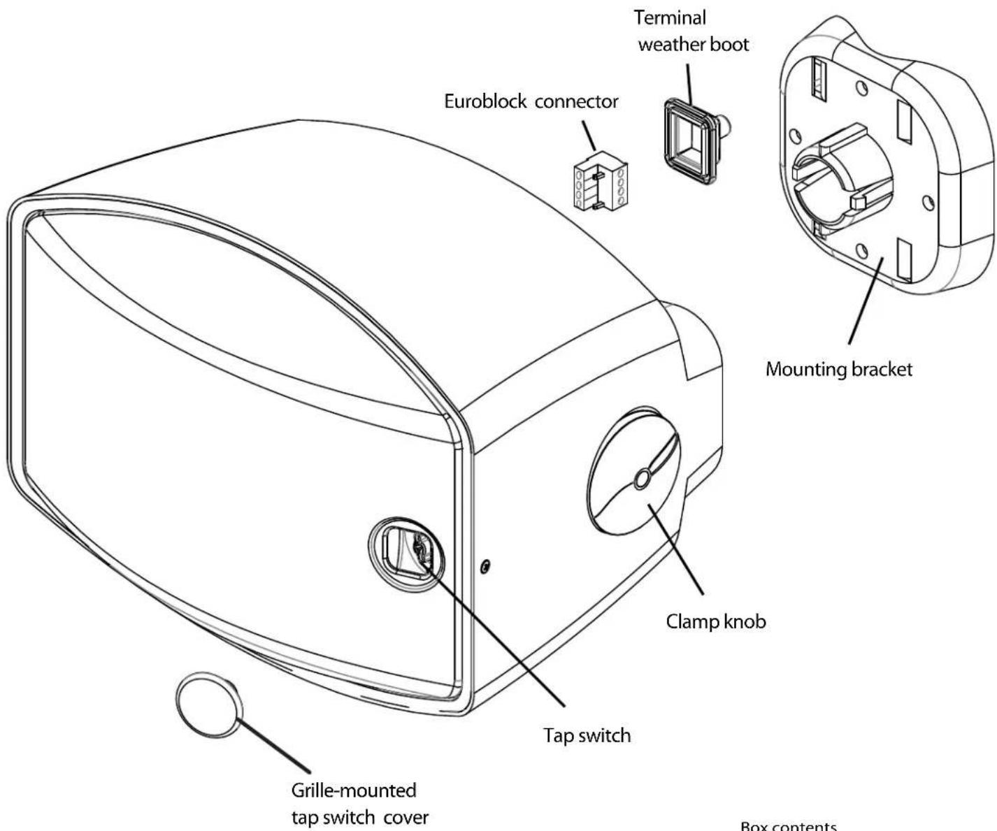
text_image
Euroblock connector Terminal weather boot Mounting bracket Clamp knob Tap switch Grille-mounted tap switch cover Box contentsBox contents
1 Speaker
1 Terminal weather boot
1 Mounting bracket
1 Safety cable
1 Safety cable anchor screws
1 Euroblock connector
1 Grille-mounted tap switch cover
1 Allen hex key
1 M3x4mm security screw
SM500i-II, SM500i-II-WX, SM590i-II, SM590i-II-WX UL1480 (UEAY) planned
©2011 SoundTube Entertainment, Inc. All rights reserved. PNNS-SMS rev 11.30.11

Warning
SoundTube speakers must be installed by a professional audio installer/contractor. For safety and for optimum audio performance, installer must follow all directions issued by SoundTube Entertainment.

Warning
Do not spec or install speaker near support beam, ventilation duct or other structure that may interfere with speaker function or dispersion.
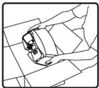
natural_image
Line drawing of a person lying on a tiled floor, wearing a helmet and holding an object (no text or symbols)- Unpack speaker and mounting hardware.
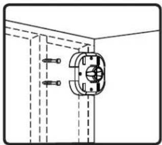
natural_image
Technical line drawing of a mechanical assembly with dashed lines indicating hidden edges (no text or symbols)- Choose a secure mounting surface with sufficient strength to reliably hold the speaker. Note: Bracket orientation does not matter for installation of the mounting bracket.
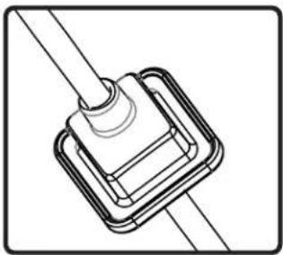
natural_image
Technical line drawing of a mechanical component with a central shaft and flange (no text or symbols)- Slip terminal weather boot over signal wire. For environmental applications, put RTV silicone around nipple and base when installation is complete.

natural_image
Diagram of a hand connecting two electrical connectors with arrows indicating rotation (no text or symbols)- Connect signal wire to 4-pin Euroblock plug. Tighten unused terminal screws. Use inside positive and negative inputs for either voice coil or distributed systems. For daisy chaining, use outside positive and negative terminals.
natural_image
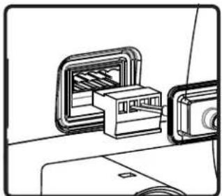
Technical line drawing of a connector assembly with no visible text or symbols- Insert 4-pin Euroblock plug into Euroblock jack on rear of speaker. Connectors are keyed for polarity. Terminal weather boot will seal the enclosure on rear of speaker.
natural_image
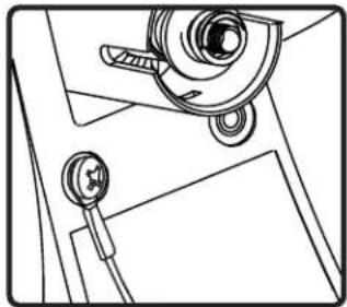
Technical line drawing of a mechanical assembly with no visible text or symbols- Use supplied screw to connect the safety cable to one of the inserts on the rear panel of the speaker. Connect other end of the safety cable to a secure mounting point.
text_image
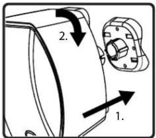
1. 2.- Line up bracket ribs with mounting tube slots and press speaker onto bracket. Twist clockwise until speaker clicks. Speaker is now locked in place.
natural_image
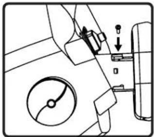
Technical diagram of a mechanical assembly with no visible text or symbols- If speaker is within reach of the public, or extra security is desired, install the included M3x4mm security screw.
text_image
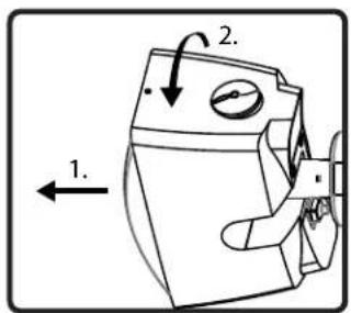
1. 2.- Firmly grip speaker and pull it away from the wall to rotate to to desired mounting angle about the mounting shaft axis. Simply release speaker back toward the wall to lock into place.
natural_image
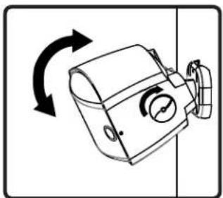
Diagram of a mechanical device with bidirectional arrows indicating rotational motion (no text or symbols)- Make sure knob is loo and aim speaker in desired direction (0 to 90). Tighten the knob to lock the speaker in place. FINGER TIGHT IS SUFFICIENT- DO NOT OVER TIGHTEN.
natural_image
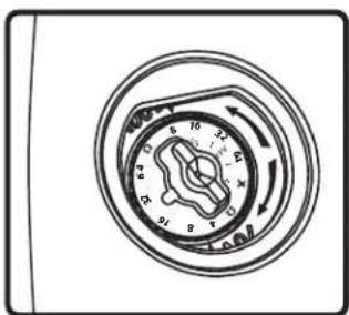
Circular diagram with concentric rings and directional arrows, no text or symbols present- Select the tap position by removing the rubber plug on grille to access rotary switch. Switch is preset to maximum tap setting in 70.7 V mode. Select desired setting and reinsert rubber plug.
natural_image
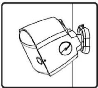
Line drawing of a mechanical device with no visible text or symbols- Done.
To loosen, use included hex key.