99-5027 - Kit voiture Metra - Kostenlose Bedienungsanleitung
Finden Sie kostenlos die Bedienungsanleitung des Geräts 99-5027 Metra als PDF.


Benutzerfragen zu 99-5027 Metra
0 Frage zu diesem Gerät. Beantworten Sie die, die Sie kennen, oder stellen Sie Ihre eigene.
Eine neue Frage zu diesem Gerät stellen
Laden Sie die Anleitung für Ihr Kit voiture kostenlos im PDF-Format! Finden Sie Ihr Handbuch 99-5027 - Metra und nehmen Sie Ihr elektronisches Gerät wieder in die Hand. Auf dieser Seite sind alle Dokumente veröffentlicht, die für die Verwendung Ihres Geräts notwendig sind. 99-5027 von der Marke Metra.
BEDIENUNGSANLEITUNG 99-5027 Metra

INSTALLATION INSTRUCTIONS FOR PART 99-5027
APPLICATIONS
See application list inside
Ford/Mazda multi-kit 1995-2011 99-5027
KIT FEATURES
• DIN radio provision with pocket
• ISO DIN radio provision with pocket
• DIN radio provision
• ISO DIN radio provision
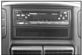
natural_image
Interior view of a car dashboard with air conditioner and control panel (no visible text or symbols)KIT COMPONENTS
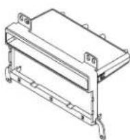
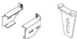
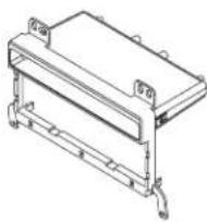
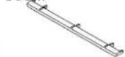
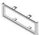
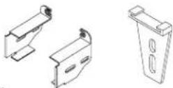
- A) Radio housing • B) Radio housing trim piece "A" • C) Radio housing trim piece "B" • D) ISO Brackets
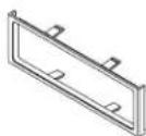
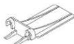
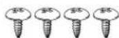
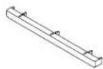
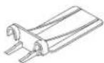
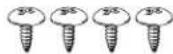
• E) Rear support • F) ISO Trim plate • G) Mounting bracket • H) (4) #8 x 3/8" Truss head Phillips screws
natural_image
Technical line drawing of a mechanical assembly with mounting brackets and connectors (no text or symbols)B C EDA
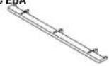
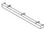
F
G
H
WIRING & ANTENNA CONNECTIONS (sold separately)
Wiring Harness:
• 70-5519 - Ford amplified harness 1998-08
• 70-5520 - Ford harness 2003-up
• 70-5521 - Ford amplified harness 2003-up
• 70-1771 - Ford harness 1998-up
Antenna Adapter:
- Not required
TOOLS REQUIRED
- Panel removal tool • Phillips screwdriver
- Small flat blade screwdriver
• 86-5618 Ford radio removal keys
CAUTION: Metra recommends disconnecting the negative battery terminal before beginning any installation. All accessories, switches, and especially air bag indicator lights must be plugged in before reconnecting the battery or cycling the ignition.
NOTE: Refer to the instructions included with the aftermarket radio.

99-5027
Applications
Ford
Crown Victoria 1995-2011
Econoline 1997-2008
Expedition 1997-2002
Expedition (without NAV) ......2003-2006
Explorer 1995-2001
Explorer 2002-2005
F-150 1997-2004
F-250 1999-2004
F-350 1999-2004
F-550 1999-2004
Mustang 2001-2004
Ranger 1995-2011
Windstar 1999-2003
Excursion 2000-2005
Lincoln
Aviator 2003-2005
Continental 1995-1997
Blackwood 2001-2003
Mark 8 1996-1998
Town Car 1995-2002
Navigator 1997-2002
Navigator (without NAV) ......2003-2006
Mazda
B-Series Pickup 1995-2009
Mercury
Grand Marquis 1995-2010
Mountaineer 1997-2001
Mountaineer 2002-2005
Marauder 2003-2004
Mariner 2005-2007
Table of Contents
Dash Disassembly
- Ford Crown Victoria 1995-2011 .... 3 Mazda B-Series Pickup 1995-2009 .... 3
– Ford Econoline 1997-2008 ...... 3 – Mercury Grand Marquis 1995-2010 ...... 3
– Ford Excursion 2000-2005 .... 4 – Mercury Marauder 2003-2004 .... 3
– Ford Expedition 1997-2002 .... 4 – Mercury Mariner 2005-2007 .... 3
- Ford Expedition (without NAV) 2003-2006 .... 5 - Mercury Mountaineer 1997-2001 .... 3
– Ford Explorer 1995-2001 .... 3 – Mercury Mountaineer 2002-2005 .... 6
– Ford Explorer 2002-2005 ...... 6
- Ford F-150 1997-2004 .... 4 Kit Assembly
- Ford F-250 1999-2004 .... 3 - All models .... 8
- Ford F-350 1999-2004 .... 3 - DIN radio provision with pocket.... 9
- Ford F-550 1999-2004 .... 3 - ISO DIN radio provision with pocket .... 10
– Ford Mustang 2001-2004 .... 5 – DIN radio provision .... 11
– Ford Ranger 1995-2011 .... 3 – ISO DIN radio provision .... 12
– Lincoln Aviator 2003-2005 ...... 7
– Lincoln Blackwood 2001-2003 .... 4
– Lincoln Continental 1995-1997 ...... 3
– Lincoln Mark 8 1996-1998 ...... 3
– Lincoln Navigator 1997-2002 ...... 3
– Lincoln Navigator (without NAV) 2003-2006 ..... 6

Dash Disassembly 99-5027
Ford Crown Victoria 1995-2011/Econoline 1997-2008/Explorer 1995-2001/F-250 1999-2004/ F-350 1999-2004/F-550 1999-2004/Ranger 1995-2011, Lincoln Continental 1995-1997/Mark 8 1996-1998/Town Car 1995-2002, Mazda B-Series Pickup 1995-2009, Mercury Grand Marquis 1995-2010/Mountaineer 1997-2001/Marauder 2003-2004/Mariner 2005-2007
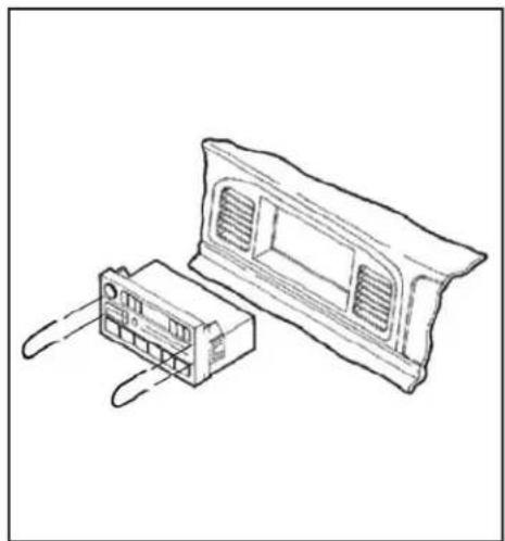
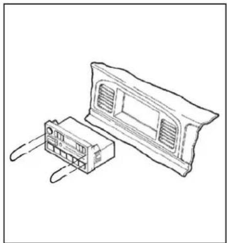
- Using Metra's 86-5618, pull the factory radio from the dash and disconnect the wiring. (Figure A)
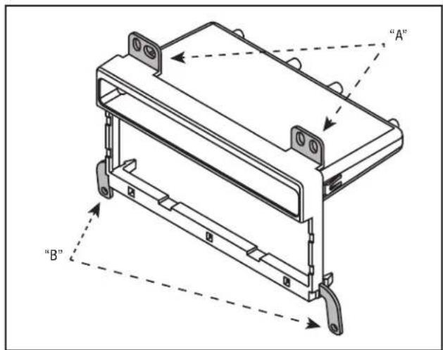
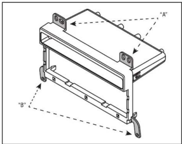
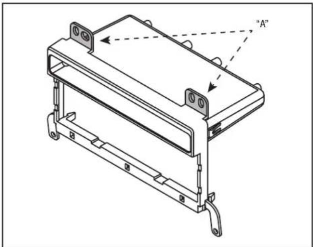
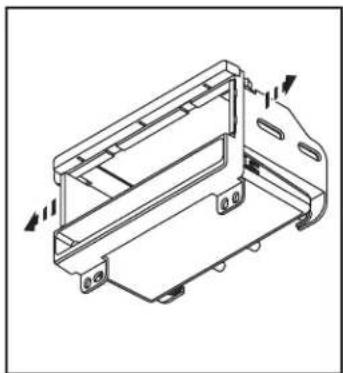
- Cut and remove the top mounting legs "A" and the bottom mounting legs "B" from the radio housing. (Figure B)
Continue to kit assembly
natural_image
Line drawing of two electronic components: a connector housing and a plastic cover (no text or symbols)(Figure A)
text_image
"A" "B"(Figure B)

Dash Disassembly 99-5027
Ford Expedition 1997-2002/F-150 1997-2004/
Excursion 2000-2005, Lincoln Blackwood 2001-2003/
Navigator 1997-2002
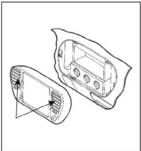
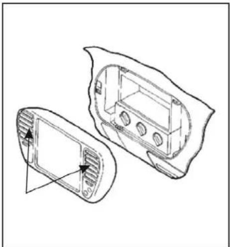
- Place your index fingers on the inner edges of the A/C vents and push inward. Grasp the exposed lip of each vent opening and pull out on the radio trim bezel. Remove the dash trim bezel (airbag wiring does not need to be disconnected). (Figure A)
Using Metra's 86-5618, pull the factory radio from the dash and disconnect the wiring.
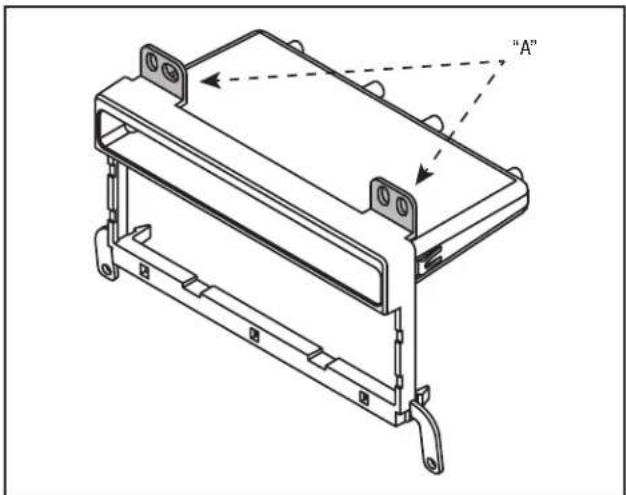
- Cut and remove the top mounting legs "A" from the radio housing. (Figure B)
Continue to kit assembly
natural_image
Technical line drawing of a vehicle chassis with two views showing internal components (no text or symbols)(Figure A)
natural_image
Technical line drawing of a mechanical housing or bracket assembly with mounting flanges and mounting holes (no text or symbols)(Figure B)

Dash Disassembly 99-5027
Ford Mustang
2001-2004
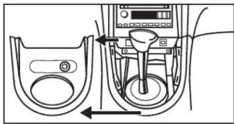
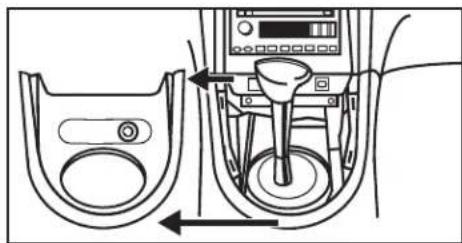
- Unclip and remove shift lever trim panel. (Figure A)
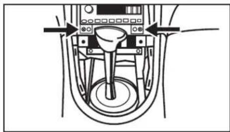
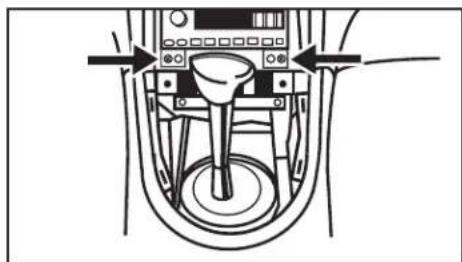
- Unclip and remove the entire panel surrounding the radio and climate controls including the vents. (Figure B)
- Remove (2) 9/32" screws securing radio. (Figure B)
Continue to kit assembly
natural_image
Diagram of a car intake system showing valve and control panel (no text or labels)(Figure A)
natural_image
Diagram of a mechanical device with a central knob and control panel, showing directional arrows (no text or symbols)(Figure B)
Ford Expedition (without NAV)
2003-2006
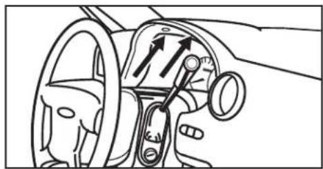
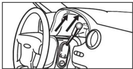
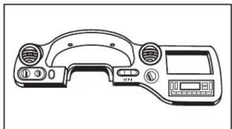
- Remove (2) 9/32" screws from above instrument cluster. (Figure A)
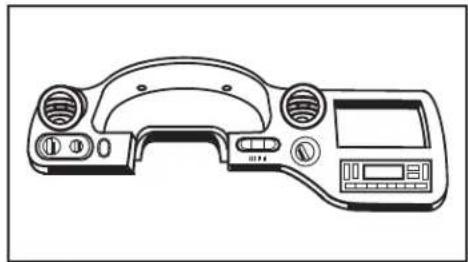
- Unclip and remove entire panel surrounding radio, climate controls, and instrument cluster. (Figure B)
- Remove (2) 9/32" screws securing radio. Continue to kit assembly
natural_image
Interior view of a car dashboard with steering wheel, steering wheel, and directional arrows indicating motion (no text or symbols)(Figure A)
natural_image
Line drawing of a device control panel with buttons and display (no text or symbols)(Figure B)

Dash Disassembly 99-5027
Ford Explorer/Mercury Mountaineer 2002-2005
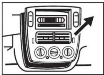
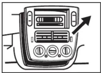
- Unclip and remove entire panel surrounding radio including climate controls and vents. (Figure A)
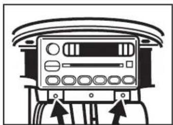
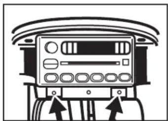
- Remove (2) 9/32" screws securing radio. (Figure B) Continue to kit assembly
natural_image
Line drawing of a car infotainment device with control panel and directional arrow (no text or symbols)(Figure A)
natural_image
Front view of a vehicle air conditioning unit with control panel and buttons (no text or symbols visible)(Figure B)
Lincoln Navigator (without NAV) 2003-2006
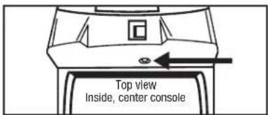
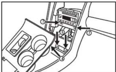
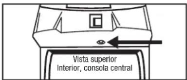
- Open center console and remove (1) push pin from back of power window switch panel. (Figure A)
- Unclip and remove panel.
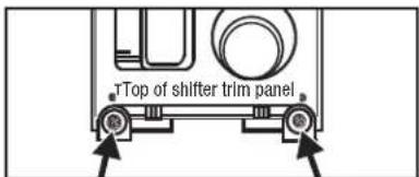
- Remove (2) 9/32" screws exposed on shifter panel then unclip and move shifter panel off to side. (Figure B, C)
- Remove (2) 9/32" screws exposed under ashtray assembly. (Figure C)
- Unclip and remove entire panel surrounding climate controls and radio.
- Remove (2) 9/32" screws securing radio. (Figure C) Continue to kit assembly
text_image
Top view Inside, center console(Figure A)
text_image
Top of shifter trim panel(Figure B)
text_image
Diagram of car interior air intake system with numbered components and directional arrows indicating flow or movement(Figure C)

Dash Disassembly 99-5027
Lincoln Aviator 2003-2005
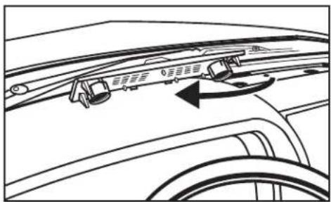
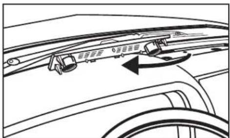
- Unclip and remove vent panel above radio on top of dashboard. (Figure A)
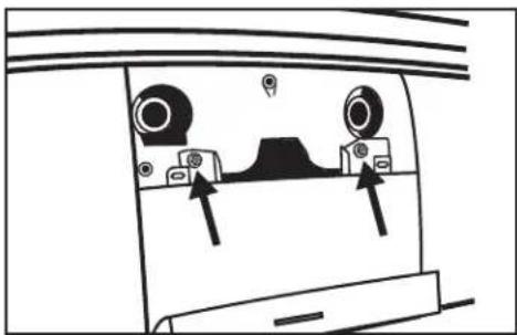
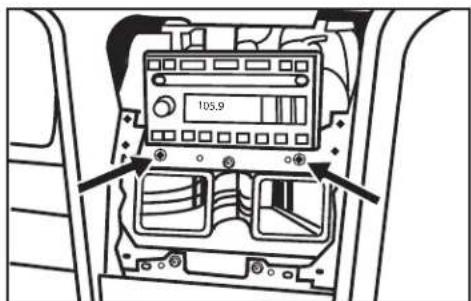
- Remove (2) 9/32" screws exposed under panel removed in step 1. (Figure B)
- Unclip and remove panel around radio with door in it. (Figure C)
- Unclip and remove vents below radio. (Figure D)
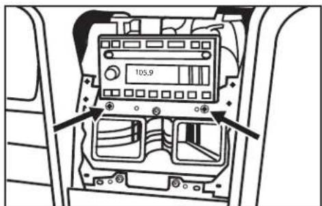
- Remove (2) 9/32" screws securing radio. (Figure E)
Continue to kit assembly
natural_image
Diagram of a device rear panel with two circular components and directional arrows indicating movement or force (no text or symbols)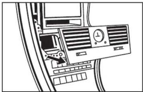
natural_image
Top-down schematic of a computer ventilation system with fan, buttons, and ventilation unit (no text or labels)(Figure D)(Figure B)
natural_image
Diagram of a car interior with two vehicles and directional arrows indicating motion (no text or symbols)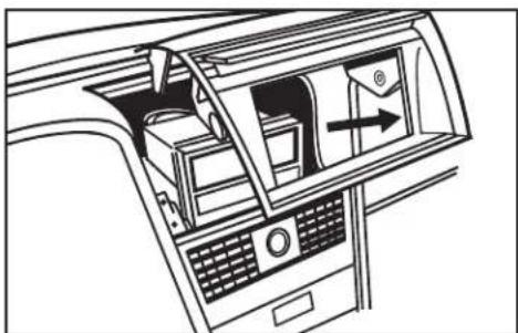
natural_image
Interior view of a car showing airflow direction and control panel (no text or symbols)(Figure C)
text_image
105,9(Figure E)(Figure A)

99-5027
All models
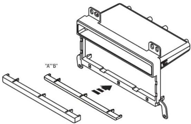
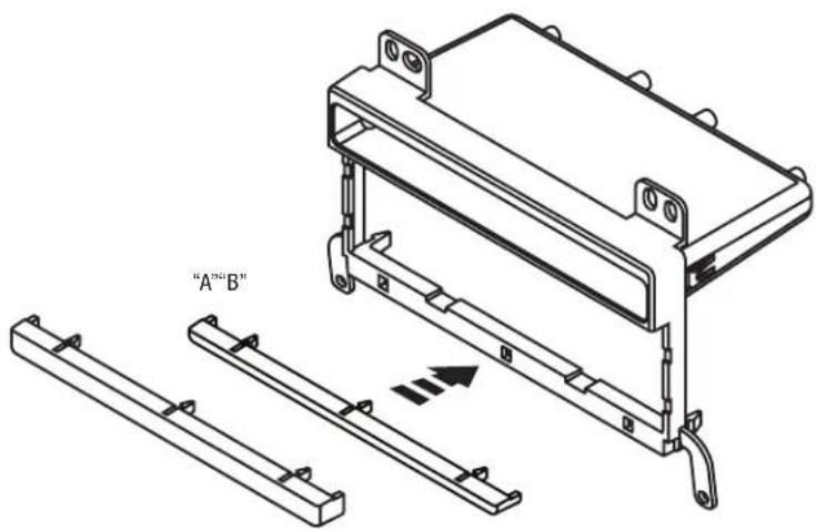
- Attach the corresponding radio housing trim piece to the radio housing. (Figure A)
The following applications will use radio housing trim piece "B" (thicker trim piece):
Ford Mustang 2001-2004
Ford Expedition (without NAV) 2003-2006
Ford Explorer 2002-2005
Lincoln Aviator 2003-2005
Lincoln Navigator (without NAV) 2003-2006
Mercury Mountaineer 2002-2005
Continue to kit assembly, pages 9-10
All other applications will use radio housing trim piece "A" (thinner trim piece):
Continue to kit assembly, pages 11-12
text_image
"A""B"(Figure A)

Kit Assembly 99-5027
DIN radio provision with pocket
Ford Mustang 2001-2004/Expedition (without NAV) 2003-2006/Explorer 2002-2005, Lincoln Aviator 2002-2005/Navigator (without NAV) 2003-2006, Mercury Mountaineer 2002-2005 (if your vehicle is not listed above go to page 11):
-
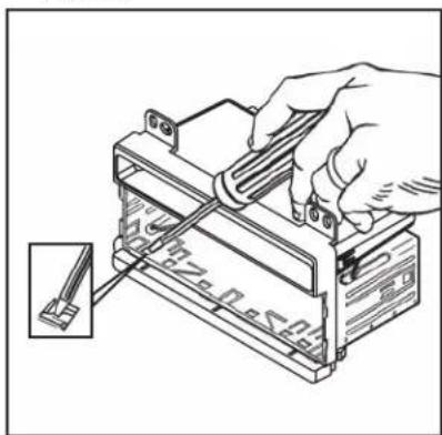
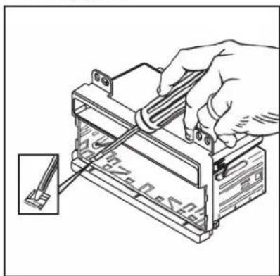
Slide the DIN cage into the radio housing and secure by bending the metal locking tabs down. (Figure A)
-
Slide the aftermarket radio into the cage and secure. (Figure B)
- Mount the support to the back of the radio using the hardware included with the unit. (Figure B)
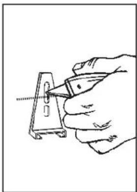
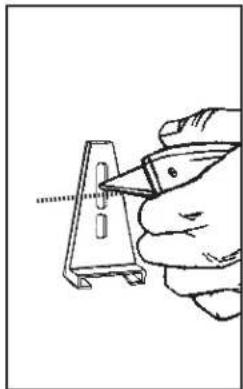
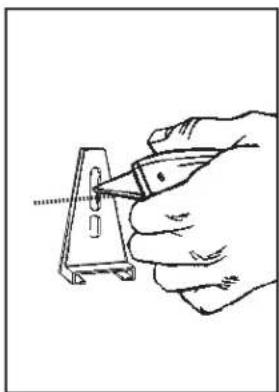
Note: On Ford Expedition and Lincoln Navigator DIN head and ISO kit assemblies you must cut the rear support bracket for clearance. (Figure C)
- Locate the factory wiring harness and antenna plug in the dash. Metra recommends using the proper mating adapters from Metra and/or AXXESS.
- Reassemble dash in reverse order of disassembly.
natural_image
Illustration of a hand using a tool to adjust or install a battery component, with an inset showing a small component (no text or symbols visible)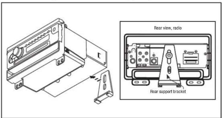
text_image
Rear view, radio Rear support bracket(Figure B)
natural_image
Hand holding a tool interacting with a metal bracket (no text or symbols visible)(Figure C)(Figure A)

Kit Assembly 99-5027
ISO DIN radio provision with pocket
Ford Mustang 2001-2004/Expedition (without NAV) 2003-2006/Explorer 2002-2005, Lincoln Aviator 2002-2005/Navigator (without NAV) 2003-2006, Mercury Mountaineer 2002-2005 (if your vehicle is not listed above go to page 12):
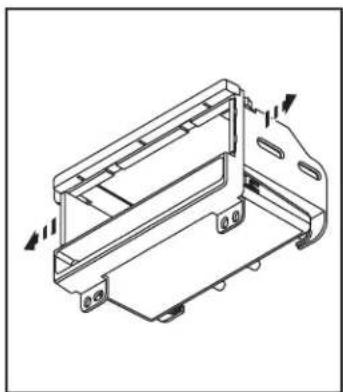
- Secure the ISO brackets to the back of the radio housing with (2) #8 x 3/8" Phillips screws with the front edge of the bracket inside the radio opening.
(Figure A)
- Slide the aftermarket radio into the radio opening and secure with the radio's supplied screws. (Figure B)
- Mount the support to the back of the radio using the hardware included with the unit. (Figure B)
Note: On Ford Expedition and Lincoln Navigator DIN
head and ISO kit assemblies you must cut the rear support bracket for clearance. (Figure C)
- Snap trim plate into the radio housing. (Figure B)
- Locate the factory wiring harness and antenna plug in the dash. Metra recommends using the proper mating adapters from Metra and/or AXXESS.
- Reassemble dash in reverse order of disassembly.
natural_image
Technical line drawing of a mechanical housing or enclosure with mounting brackets and internal components (no text or symbols)(Figure A)

text_image
Rear view, radio Rear support bracket(Figure B) (Figure C)
natural_image
Hand holding a metal bracket with a tool, no visible text or symbols
Kit Assembly 99-5027
DIN radio provision
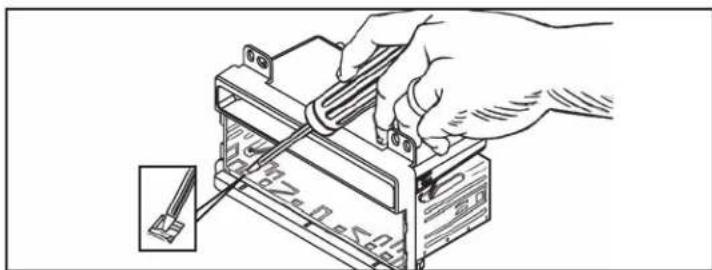
- Slide the DIN cage into the radio housing and secure by bending the metal locking tabs down. (Figure A)
- Secure the mounting bracket to the back of the radio housing with (2) 3/8" Phillips pan-head screws supplied. (Figure B)
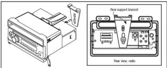
- Slide the aftermarket radio into the cage and secure. (Figure C)
- Slide the rear support onto the mounting bracket and mount the support to the back of the radio using the hardware included with the unit. (Figure C)
- Locate the factory wiring harness and antenna plug in the dash. Metra recommends using the proper mating adapters from Metra and/or AXXESS.
- Reassemble dash in reverse order of disassembly.
natural_image
Illustration of a hand using a tool to adjust or install a battery component, with an inset showing a cable being inserted (no text or symbols visible)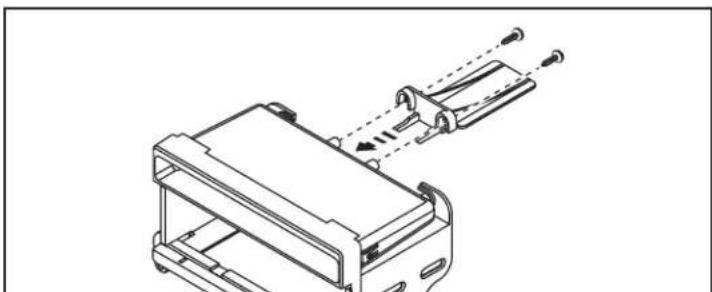
natural_image
Technical line drawing of a mechanical assembly with no visible text or symbols(Figure B)
text_image
Rear support bracket Rear view, radio(Figure C)(Figure A)

Kit Assembly 99-5027
ISO DIN radio provision
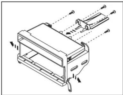
- Secure the ISO brackets to the back of the radio housing with (2) #8 x 3/8" Phillips screws with the front edge to the bracket inside the radio opening. (Figure A)
- Secure the mounting bracket to the back of the radio housing with the (2) 3/8" Phillips pan-head screws supplied. (Figure A)
-
Slide the radio into the radio opening and secure with the radio's supplied screws. (Figure B)
-
Slide the rear support onto the mounting bracket and mount the support to the back of the radio using the hardware included with the unit. (Figure B)
- Snap the trim plate into the radio housing. (Figure B)
- Locate the factory wiring harness and antenna plug in the dash. Metra recommends using the proper mating adapters from Metra and/or AXXESS.
- Reassemble dash in reverse order of disassembly.
natural_image
Technical line drawing of a mechanical device with internal components and directional arrows indicating motion (no text or symbols)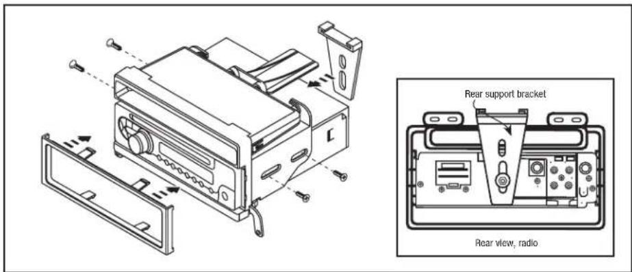
text_image
Rear support bracket Rear view, radio(Figure B)(Figure A)

99-5027
Notes

99-5027
Notes

99-5027
Notes

INSTALLATION INSTRUCTIONS FOR PART 99-5027


KNOWLEDGE IS POWER
Enhance your installation and fabrication skills by parrolling in the most recognized and suggested
mobile electronics school in our industry.
Log onto www.installerinstitute.com or call
600-354-6782 for more information and take steps toward a better tomorrow.
Metra recommends MECP
certified technicians

INSTRUCCIONES DE INSTALACIÓN PARA LA PIEZA 99-5027
APLICACIONES
Lista de aplicaciones dentro
Ford/Mazda multi-kit 1995-2011 99-5027
CARACTERÍSTICAS DEL KIT
• Provisión de radio DIN con bolsillo
• Provisión de radio ISO DIN con bolsillo
• Provisión de radio DIN
• Provisión de radio ISO DIN
natural_image
Interior view of a car dashboard with a digital display and control buttons (no visible text or symbols)COMPONENTES DEL KIT
- A) Carcasa del radio • B) Moldura de la carcasa del radio, pieza “A” • C) Moldura de la carcasa del radio, pieza “B” • D) Soportes ISO • E) Soporte trasero • F) Placa de moldura ISO • G) Soporte de montaje • H) (4) tornillos Phillips de cabeza segmentada #8 x 3/8"
natural_image
Technical line drawing of a mechanical assembly with mounting brackets and a central frame (no text or symbols)B C EDA
F
G
H
CABLEADO Y CONEXIONES DE ANTENA
Arnés de cableado: (se venden por separado)
- 70-5519 - Arnés amplificado para Ford 1998-08
• 70-5520 - Arnés Ford 2003 y más recientes - 70-5521 - Arnés amplificado para Ford 2003 y más recientes
• 70-1771 - Arnés Ford 1998 y más recientes
Adaptador de antena: • No se requiere
HERRAMIENTAS REQUERIDAS
- Herramienta de remoción de panel
- Destornillador Phillips • Destornillador plano pequeño • Llaves de remoción Ford 86-5618
PRECAUCIÓN: Metra recomienda desconectar el terminal negativo de la batería antes de comenzar cualquier instalación. Todos los accesorios, interruptores y, especialmente, las luces indicadoras de airbag deben estar enchufados antes de volver a conectar la batería o comenzar el ciclo de ignición.
NOTA: Remítase a las instrucciones incluidas con el radio de postventa.

99-5027
Aplicaciones
Ford
Crown Victoria 1995-2011
Econoline 1997-2008
Expedition 1997-2002
Expedition (sin NAV) ......2003-2006
Explorer 1995-2001
Explorer 2002-2005
F-150 1997-2004
F-250 1999-2004
F-350 1999-2004
F-550 1999-2004
Mustang 2001-2004
Ranger 1995-2011
Windstar 1999-2003
Excursion 2000-2005
Lincoln
Aviator 2003-2005
Continental 1995-1997
Blackwood 2001-2003
Mark 8 1996-1998
Town Car 1995-2002
Navigator 1997-2002
Navigator (sin NAV) ......2003-2006
Mazda
B-Series Pickup 1995-2009
Mercury
Grand Marquis 1995-2010
Mountaineer 1997-2001
Mountaineer 2002-2005
Marauder 2003-2004
Mariner 2005-2007
Indice
Desmontaje del tablero
- Ford Crown Victoria 1995-2011 .... 3 Mazda B-Series Pickup 1995-2009 .... 3
– Ford Econoline 1997-2008 ...... 3 – Mercury Grand Marquis 1995-2010 ...... 3
– Ford Excursion 2000-2005 ...... 4 – Mercury Marauder 2003-2004 ...... 3
– Ford Expedition 1997-2002 ...... 4 – Mercury Mariner 2005-2007 ...... 3
– Ford Expedition (sin NAV) 2003-2006 .... 5 – Mercury Mountaineer 1997-2001 .... 3
– Ford Explorer 1995-2001 .... 3 – Mercury Mountaineer 2002-2005 .... 6
– Ford Explorer 2002-2005 ...... 6
- Ford F-150 1997-2004 .... 4 Ensamble del kit
– Ford F-250 1999-2004 .... 3 – Todos los modelos .... 8
– Ford F-350 1999-2004 ...... 3 – Provisión de radio DIN con bolsillo ...... 9
– Ford F-550 1999-2004 ...... 3 – ISO Provisión de radio DIN con bolsillo ...... 10
– Ford Mustang 2001-2004 ...... 5 – Provisión de radio DIN...... 11
– Ford Ranger 1995-2011 .... 3 – Provisión de radio ISO DIN .... 12
– Lincoln Aviator 2003-2005 ...... 7
– Lincoln Blackwood 2001-2003 ...... 4
– Lincoln Continental 1995-1997 ...... 3
– Lincoln Mark 8 1996-1998 ...... 3
– Lincoln Navigator 1997-2002 ...... 3
– Lincoln Navigator (sin NAV) 2003-2006 ...... 6

Desmontaje del tablero 99-5027
Ford Crown Victoria 1995-2011/Econoline 1997-2008/Explorer 1995-2001/F-250 1999-2004/ F-350 1999-2004/F-550 1999-2004/Ranger 1995-2011, Lincoln Continental 1995-1997/Mark 8 1996-1998/Town Car 1995-2002, Mazda B-Series Pickup 1995-2009, Mercury Grand Marquis 1995-2010/Mountaineer 1997-2001/Marauder 2003-2004/Mariner 2005-2007
- Usando las llaves 86-5618 de Metra, jale la unidad central de fábrica del tablero y desconecte el cableado. (Figura A)
- Corte y quite la patas de montaje superior "A" y las patas de montaje inferior "B" de la carcasa del radio. (Figura B)
Continuará al ensamble del kit
natural_image
Line drawing of two electronic components: a connector housing and a plastic cover (no text or symbols)(Figura A)
text_image
"A" "B"(Figura B)

Desmontaje del tablero 99-5027
Ford Expedition 1997-2002/F-150 1997-2004/
Excursion 2000-2005, Lincoln Blackwood 2001-2003/
Navigator 1997-2002
- Coloque sus dedos índices en los bordes internos de las rejillas del aire acondicionado y jale hacia adentro. Sujete el borde expuesto de cada apertura de rejilla y jale hacia afuera el bisel de la moldura del radio. Quite el bisel de la moldura del tablero (no es necesario desconectar el cableado de la bolsa de aire). (Figura A)
Usando las llaves 86-5618 de Metra, jale la unidad central de fábrica del tablero y desconecte el cableado.
- Corte y quite las patas de montaje superior "A" de la carcasa del radio. (Figura B)
Continuará al ensamble del kit
natural_image
Technical line drawing of a vehicle chassis with two views: front and side (no text or symbols)(Figura A)
natural_image
Technical line drawing of a mechanical housing or bracket assembly with mounting flanges and mounting holes (no text or symbols)(Figura B)

Desmontaje del tablero 99-5027
Ford Mustang 2001-2004
- Desenganche y quite el panel de la moldura de la palanca de velocidades. (Figura A)
- Desenganche y retire todo el panel que rodea el radio y los controles del clima, incluyendo las rejillas. (Figura B)
- Retire los (2) tornillos de 9/32" que sostienen el radio. (Figura B)
Continuará al ensamble del kit
natural_image
Diagram of a car intake system showing hand shift and control panel (no text or labels)(Figura A)
natural_image
Diagram of a mechanical device with a central fork and control panel, showing directional arrows (no text or symbols)(Figura B)
Ford Expedition (sin NAV)
2003-2006
- Quite los (2) tornillos de 9/32" de arriba del conjunto de instrumentos. (Figura A)
- Desenganche y quite todo el panel que rodea el radio, los controles del clima y el conjunto de instrumentos. (Figura B)
- Retire los (2) tornillos de 9/32" que sostienen el radio. Continuará al ensamble del kit
natural_image
Interior view of a car dashboard with steering wheel, steering wheel, and directional arrows indicating motion (no text or symbols)(Figura A)
natural_image
Line drawing of a handheld electronic device with control panel and display (no text or symbols)(Figura B)

Desmontaje del tablero 99-5027
Ford Explorer/Mercury Mountaineer 2002-2005
- Desenganche y quite todo el panel que rodea el radio, incluyendo los controles del clima y las rejillas. (Figura A)
- Retire los (2) tornillos de 9/32" que sostienen el radio. (Figura B)
Continuará al ensamble del kit
natural_image
Diagram of a car air conditioning unit with directional arrow indicating motion (no text or symbols)(Figura A)
natural_image
Front view of a vehicle air conditioning unit with control panel and buttons (no text or symbols visible)(Figura B)
Lincoln Navigator (sin NAV) 2003-2006
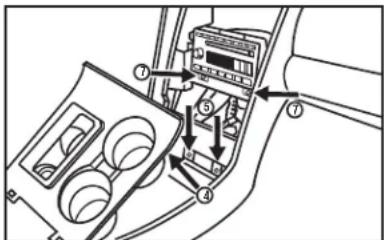
- Abra la consola central y quite (1) chincheta de la parte posterior del panel interruptor de la ventanilla eléctrica. (Figura A)
- Desenganche y quite el panel.
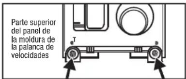
- Quite los (2) tornillos de 9/32" expuestos del panel de la palanca de velocidades y luego desenganche y mueva la palanca de velocidades a un lado. (Figura B, C)
- Quite los (2) tornillos de 9/32" expuestos debajo del ensamble del cenicero. (Figura C)
- Desenganche y quite todo el panel que rodea los controles del clima y el radio.
- Retire los (2) tornillos de 9/32" que sostienen el radio. (Figura C) Continuará al ensamble del kit
text_image
Vista superior Interior, consola central(Figura A)
text_image
Parte superior del panel de la moldura de la palanca de velocidades(Figura B)
text_image
Diagram of car interior air intake system with numbered components and directional arrows indicating flow or movement(Figura C)

Desmontaje del tablero 99-5027
Lincoln Aviator 2003-2005
- Desenganche y quite el panel de la rejilla arriba del radio sobre el tablero. (Figura A)
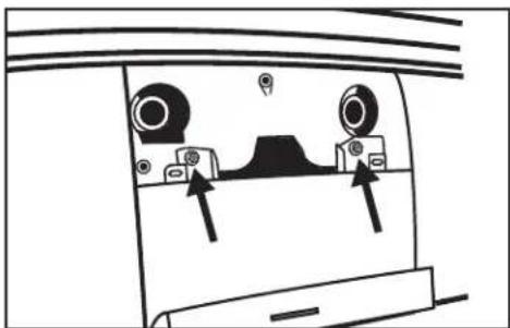
- Quite los (2) tornillos de 9/32" expuestos debajo del panel que quitó en el paso 1. (Figura B)
- Desenganche y quite el panel que rodea el radio con la puerta incluida. (Figura C)
- Desenganche y quite las rejillas debajo del radio (Figura D)
- Retire los (2) tornillos de 9/32" que sostienen el radio. (Figura E)
Continuará al ensamble del kit
natural_image
Diagram of a device rear panel with two circular components and directional arrows indicating movement or force (no text or symbols)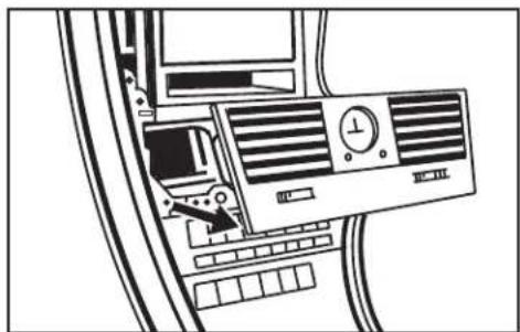
natural_image
Top-down schematic of an air conditioning unit with control panel and fan (no text or labels)(Figura D)(Figura B)
natural_image
Diagram of a car interior showing two vehicles moving on a curved road, with an arrow indicating direction (no text or symbols present)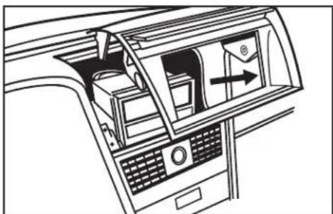
natural_image
Interior view of a car showing the dashboard, air vent, and fan (no text or symbols)(Figura C)
text_image
105.9(Figura E)(Figura A)

99-5027
Todos los modelos
- Una la pieza correspondiente de la moldura de la carcasa del radio a la carcasa del radio. (Figura A)
Las siguientes aplicaciones utilizarán la pieza "B" de la moldura de la carcasa del radio (pieza más gruesa de moldura):
Ford Mustang 2001-2004
Ford Expedition (sin NAV) 2003-2006
Ford Explorer 2002-2005
Lincoln Aviator 2003-2005
Lincoln Navigator (sin NAV) 2003-2006
Mercury Mountaineer 2002-2005
Continuará al ensamble del kit, páginas 9-10
Todas las demás aplicaciones utilizarán la pieza "A" de la moldura de la carcasa del radio (pieza más delgada de moldura):
Continuará al ensamble del kit, páginas 11-12
text_image
"A""B"(Figura A)

Ensamble del kit 99-5027
Provisión de radio DIN con bolsillo
Ford Mustang 2001-2004/Expedition (sin NAV) 2003-2006/Explorer 2002-2005, Lincoln Aviator 2002-2005/Navigator (sin NAV) 2003-2006, Mercury Mountaineer 2002-2005 (si su vehículo no está incluido arriba, vaya a la página 11):
-
Deslice la reja DIN en la carcasa del radio y sujétela doblando hacia abajo las pestañas de metal. (Figura A)
-
Deslice la unidad central de mercado secundario en la reja y sujétela. (Figura B)
- Monte el soporte en la parte posterior de la unidad central con la tornillería incluida con la unidad. (Figura B)
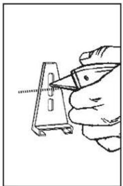
Nota: En los ensambles de kit de unidad DIN e ISO de Ford Expedition y Lincoln Navigator debe cortar
el soporte trasero para dar espacio. (Figura C)
- Ubique el arnés del cableado de fábrica en el tablero. Metra recomienda usar el adaptador de acoplamiento adecuado de Metra o AXXESS.
- Vuelva a montar el tablero en forma inversa al desmontaje.
natural_image
Illustration of a hand using a tool to adjust or install a battery component, with an inset showing a small component (no text or symbols visible)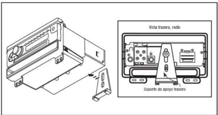
text_image
Vista trasera, radio Soporte de apoyo trasero(Figura B)
natural_image
Hand holding a tool interacting with a metal bracket (no text or symbols visible)(Figura C)(Figura A)

Ensamble del kit 99-5027
Provisión de radio ISO DIN con bolsillo
Ford Mustang 2001-2004/Expedition (sin NAV) 2003-2006/Explorer 2002-2005, Lincoln Aviator 2002-2005/Navigator (sin NAV) 2003-2006, Mercury Mountaineer 2002-2005 (si su vehículo no está incluido arriba, vaya a la página 12):
-
Sujete los soportes ISO a la parte posterior de la carcasa del radio con (2) tornillos Phillips #8 x 3/8" con el borde delantero del soporte dentro de la apertura del radio. (Figura A)
-
Deslice la unidad central de mercado secundario en la apertura del radio y sujétela con los tornillos suministrados con el radio. (Figura B)
- Monte el soporte en la parte posterior de la unidad central con la tornillería incluida con la unidad. (Figura B)
Nota: En los ensambles de kit de unidad DIN e ISO de Ford Expedition y Lincoln Navigator debe cortar
el soporte trasero para dar espacio. (Figura C)
- Coloque a presión la placa de la moldura en la carcasa del radio. (Figura B)
- Ubique el arnés del cableado de fábrica en el tablero. Metra recomienda usar el adaptador de acoplamiento adecuado de Metra o AXXESS.
- Vuelva a montar el tablero en forma inversa al desmontaje.
natural_image
Technical line drawing of a mechanical housing or enclosure component (no text or symbols)(Figura A)
text_image
Vista trasera, radio Soporte de apoyo trasero(Figura B) (Figura C)
natural_image
Hand holding a tool interacting with a metal bracket (no text or symbols visible)
Ensamble del kit 99-5027
Provisión de radio DIN
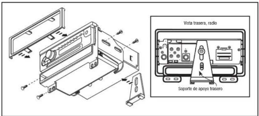
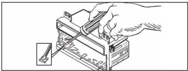
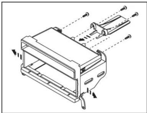
- Deslice la reja DIN en la carcasa del radio y sujétela doblando hacia abajo las pestañas de metal. (Figura A)
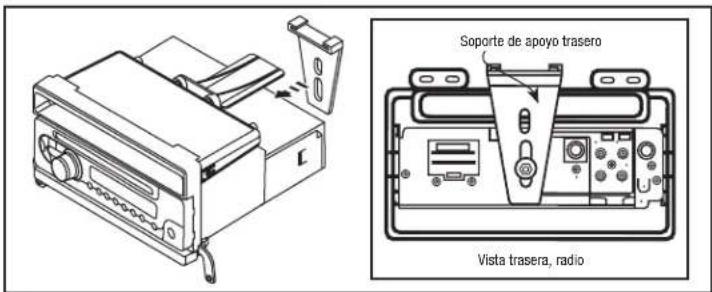
- Sujete el soporte de montaje a la parte posterior de la carcasa del radio con los (2) tornillos Phillips de cabeza troncocónica de 3/8" suministrados. (Figura B)
- Deslice la unidad central de mercado secundario en la reja y sujétela. (Figura C)
- Deslice el soporte trasero en el soporte de montaje y monte el soporte en la parte posterior de la unidad central con la tornillería incluida con la unidad. (Figura C)
- Ubique el arnés del cableado de fábrica en el tablero. Metra recomienda usar el adaptador de acoplamiento adecuado de Metra o AXXESS.
- Vuelva a montar el tablero en forma inversa al desmontaje
natural_image
Illustration of a hand using a tool to adjust or install a battery component, with an inset showing a plug inserted (no text or symbols visible)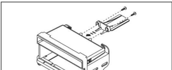
natural_image
Technical line drawing of a mechanical assembly with no visible text or symbols(Figura B)
text_image
Soporte de apoyo trasero Vista trasera, radio(Figura C)(Figura A)

Ensamble del kit 99-5027
Provisión de radio ISO DIN
- Sujete los soportes ISO a la parte posterior de la carcasa del radio con (2) tornillos Phillips #8 x 3/8" con el borde delantero al soporte dentro de la apertura del radio. (Figura A)
- Sujete el soporte de montaje a la parte posterior de la carcasa del radio con los (2) tornillos Phillips de cabeza troncocónica de 3/8" suministrados. (Figura A)
-
Deslice la unidad central en la apertura del radio y sujétela con los tornillos suministrados con el radio. (Figura B)
-
Deslice el soporte trasero en el soporte de montaje y monte el soporte en la parte posterior de la unidad central con la tornillería incluida con la unidad. (Figura B)
- Coloque a presión la placa de la moldura en la carcasa del radio. (Figura B)
- Ubique el arnés del cableado de fábrica en el tablero. Metra recomienda usar el adaptador de acoplamiento adecuado de Metra o AXXESS.
- Vuelva a montar el tablero en forma inversa al desmontaje.
natural_image
Technical line drawing of a mechanical device with internal components and directional arrows indicating motion (no text or symbols)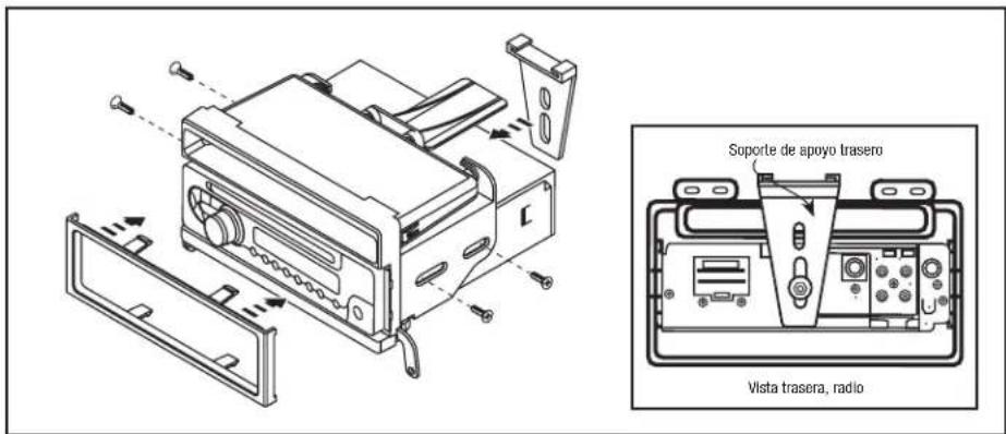
text_image
Soporte de apoyo trasero Vista trasera, radio(Figura B)(Figura A)

99-5027
Notas

99-5027
Notas

99-5027
Notas

INSTRUCCIONES DE INSTALACIÓN PARA LA PIEZA 99-5027


EL CONOCIMIENTO ES PODER
Mejore sus habilidades de instalación y fabricación inscribiéndose en la escuela de dispositivos electrónicos móviles más reconocida y respetada de nuestra industria. Registrese en www.installerinstitute.com o llame al 800-354-6782 para obtener más información y avance hacia un futuro mejor.

Metra recomienda técnicos con certificación del Programa de Certificación en Electrónica Móvil (Mobile Electronics Certification Program, MECP).