Bio-Hazard 01 - Fahrrad Westbeach - Kostenlose Bedienungsanleitung
Finden Sie kostenlos die Bedienungsanleitung des Geräts Bio-Hazard 01 Westbeach als PDF.


Benutzerfragen zu Bio-Hazard 01 Westbeach
0 Frage zu diesem Gerät. Beantworten Sie die, die Sie kennen, oder stellen Sie Ihre eigene.
Eine neue Frage zu diesem Gerät stellen
Laden Sie die Anleitung für Ihr Fahrrad kostenlos im PDF-Format! Finden Sie Ihr Handbuch Bio-Hazard 01 - Westbeach und nehmen Sie Ihr elektronisches Gerät wieder in die Hand. Auf dieser Seite sind alle Dokumente veröffentlicht, die für die Verwendung Ihres Geräts notwendig sind. Bio-Hazard 01 von der Marke Westbeach.
BEDIENUNGSANLEITUNG Bio-Hazard 01 Westbeach
WESTBEACH 20 inch BMX - BIO-HAZARD 01
Instruction Manual
WESTBEACH
natural_image
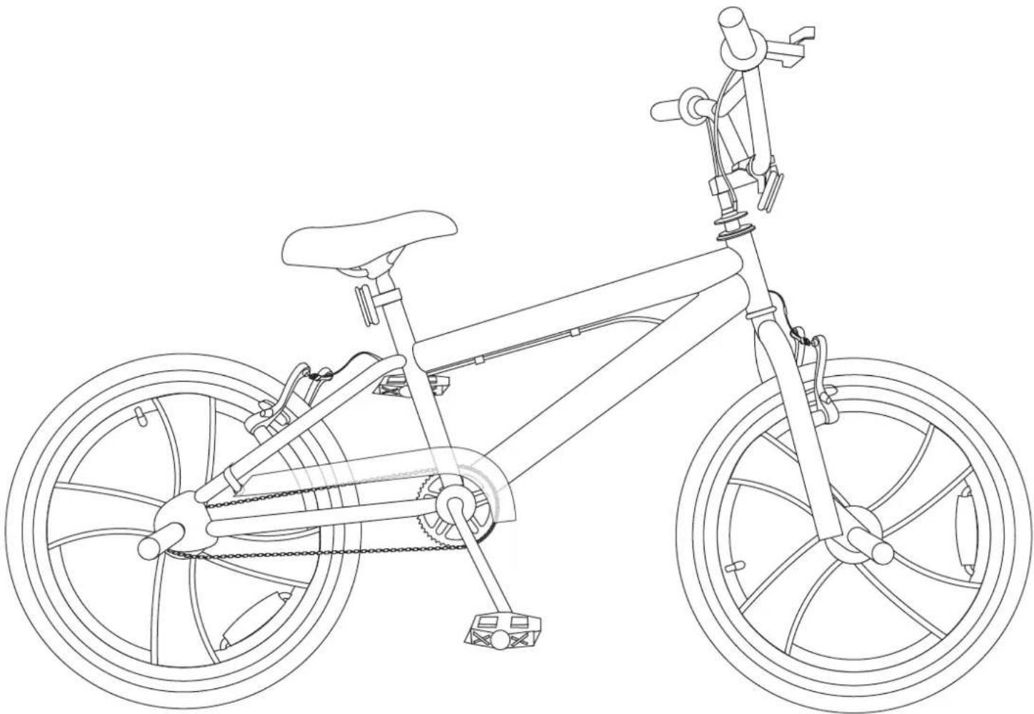
Line drawing of a bicycle with front wheel, rear wheel, and suspension components (no text or symbols)* THERE MAY BE SLIGHT VARIATIONS BETWEEN BIKE AND DRAWING.
Important - Please take time to read the instructions carefully
This BMX is supplied with a chainguard fitted.
These instructions contain important information that will help you get the best from your BMX, ensuring safe and correct assembly, use and maintenance.
If you need help or have damaged or missing parts, call the Customer Helpline on 01789 207 357.
In the Box 5
Parts 5
Tools 5
Assembly....6
Step 1....6
Step 2....7
Step 3......8
Step 4....9
Step 5....10
Step 6....13
Step 7....14
Step 8....16
Riding Advice....17
Before Riding....17
Using the Brake 17
Riding Using Personal Music Players....17
Riding in Bad Weather....18
Riding in the Dark....18
Maintenance....19
Important - Please read instructions fully before starting assembly

WARNING! Warning! This Bike has been designed, assembled and tested in accordance with the BS EN16054, max rider weight 70kg. To make sure the bike remains safe, it should only be used for recreational use. Under no circumstances should it be used for competitive cycling, stunting, jumping or acrobatic manoeuvres. These types of cycling may result in serious personal injury and damage to the bike.
WARNING! Always wear a cycle helmet when riding the bike. The helmet should be the correct size for your head and must conform to the European Standard EN1078:2012+A1:2012.
WARNING! When riding in the dark, always make sure that the bike is fitted with suitable reflectors and use a white front light and a red rear light.
WARNING! Always take extra care when riding in wet, foggy, windy or icy conditions. The brakes may not be as effective and the braking distances may be increased.
WARNING! Always wear suitable cycling clothing when riding the bike. Loose clothing which may get caught in moving parts should be avoided.
WARNING! Warning! This bike is only suitable for use by riders (including any panniers and/or luggage) with a weight of less than 70 kg (154 lb)
WARNING! BMX pedals are designed to provide greater grip capability of the pedal tread surface than that provided by an ordinary bicycle pedal. This can result in the pedal tread surface being very rough and containing sharp edges. Riders should therefore wear adequate safety protection.
WARNING! When assembling the seat post, make sure it is inserted beyond the minimum insert mark. Failure to observe this warning may lead to a potentially unstable seat post and may result in serous personal injury.
WARNING! The front and rear tyres must be fully inflated before attempting to ride the bike. Under no circumstances should the tyres be inflated above the maximum pressure stated on the side of the tyres.
WARNING! Only inflate the front and rear tyres of the bike using a bicycle pump. Do not attempt to use another type of pump to inflate the tyres.
WARNING! As with all mechanical components, the bike is subjected to wear and high stresses. Different materials and components may react to wear, stress or fatigue in different ways. If the design life of a component has been exceeded, it may suddenly fail, possibly causing injuries to the rider. Any form of crack, scratches or change of colouring in highly stressed areas indicate that the life of the component has been reached and it should be replaced.
WARNING! Ensure only genuine replacement parts are used, especially for safety critical parts.
WARNING for rim wear-if your bicycle has rim brakes (brake's that slow the bike by pressing brake pads against the rim) you should regularly check the amount of wear on the rim wall. When the rim shows signs of wearning it is time to replace your wheels. Some wheels may have a wear groove to highlight where.
Important - Please read instructions fully before starting assembly
CAUTION! Only use suitable tools to assemble the bike. The use of unsuitable tools may lead to personal injury and damage to the bike.
CAUTION! Always ensure all packaging is removed from the bike before assembly and use. Failure to remove the packaging may prevent the correct operation and may lead to personal injury and damage to the bike.
CAUTION! The safety and smooth running of the bike can only be preserved with regular maintenance. Always ensure the bike is maintained in accordance with the supplied maintenance manual.
CAUTION! Before attaching the handlebar assembly, make sure all the cables are free to move and are not tangled. Failure to observe this caution may prevent correct operation and may lead to personal injury and damage to the bike.

IMPORTANT! Before assembling the bike, check all the parts indicated in the manual are in the box. Inspect the parts for signs of damage. Do not assemble the bike if you observe any damaged components.

IMPORTANT! Always take care when removing the packaging to prevent damage to the bike.
NOTE! Always recycle the packaging in accordance with local recycling schemes.
NOTE! The pedals and crank arms have colour coded stickers to indicate which pedal matches which Crank Arm.
NOTE! The threads on the left and right pedals are different. To prevent damage to the threads, only tighten the pedals in the direction indicated on the stickers.
Recommended Tightening Information
While assembling the bike, it is recommended that, where possible, a torque spanner is used to tighten nuts and bolts. The table below provides a list of torque settings for the various nuts and bolts.
| Front Wheel Nuts | 22 - 27 Newton Metres |
| Rear Wheel Nuts | 24 - 29 Newton Metres |
| Seat Binding Nut | 12 - 17 Newton Metres |
| Seat Pillar Clamp Nut | 4 - 19 Newton Metres |
| Brake Anchor Nut | 7 - 11 Newton Metres |
| Handle Bar Clamp Nut | 5 - 19 Newton Metres |
| Head Stem Expander Bolt | 17 - 19 Newton Metres |
| Crank Cotter Pin Nuts | 5 - 10 Newton Metres |
| Brake Centre Bolt | 5 - 7 Newton Metres |
| Pedals | 35 - 40 Newton Metres |
Parts
text_image
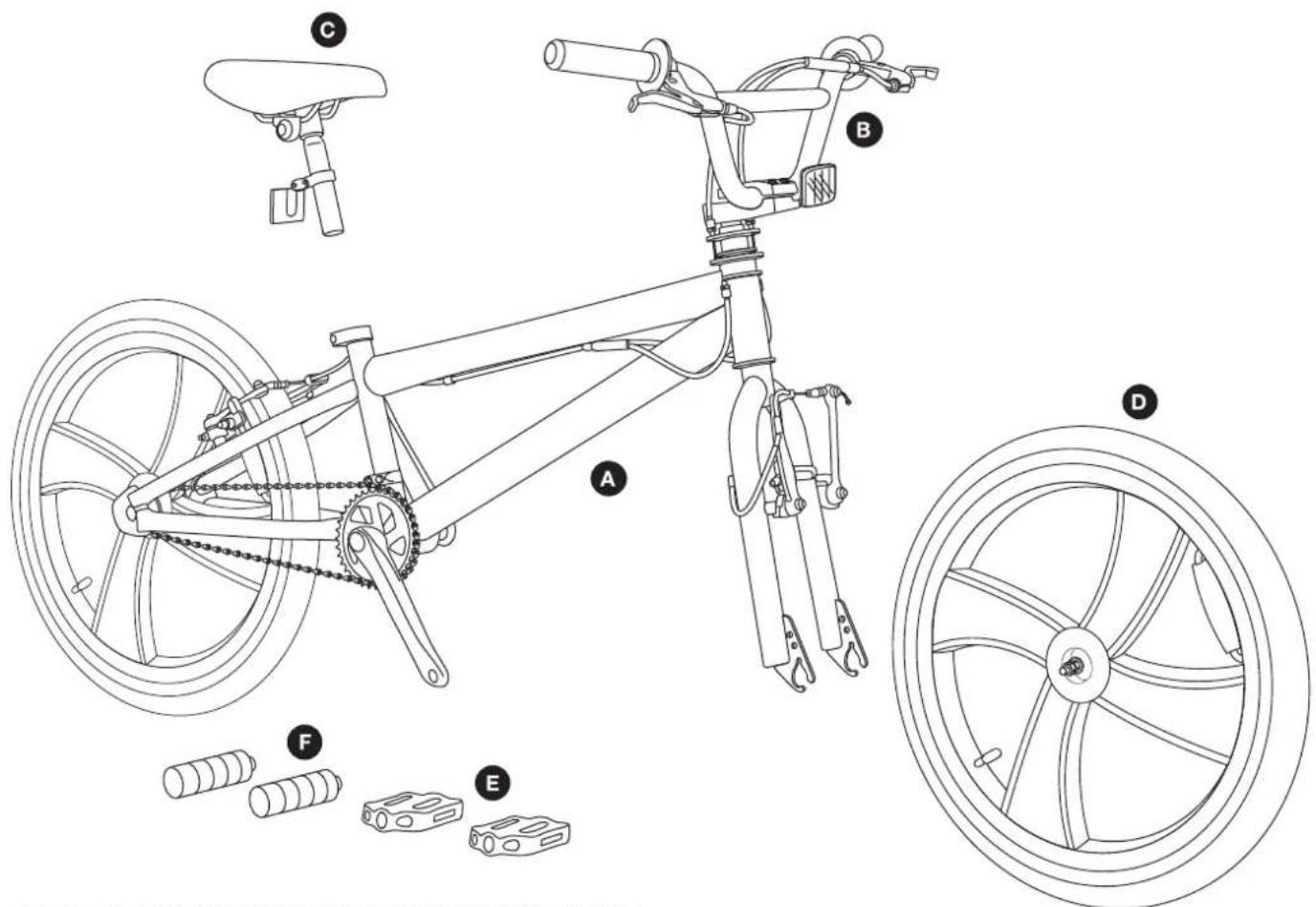
Technical diagram of a bicycle with labeled components including seat, wheel, and accessories* THERE MAY BE SLIGHT VARIATIONS BETWEEN BIKE AND DRAWING.
A Bike (supplied with rear wheel assembled)
B Handlebar and stem
© Seat post and saddle
D Front wheel
E Pedals (supplied in separate box)
F Pegs
Tools
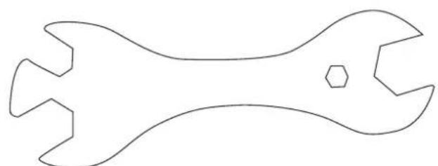
natural_image
Line drawing of a double-ended wrench with a hexagonal head (no text or symbols)Multitool (supplied in separate box)
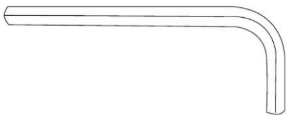
natural_image
Simple line drawing of a bent pipe or elbow joint (no text or symbols)Hexagonal key (supplied in separate box)
Step 1

IMPORTANT! Before assembling the bike, check all the parts indicated in the manual are in the box. Inspect the parts for signs of damage. Do not assemble the bike if you observe any damaged components.
IMPORTANT! Always take care when removing the packaging to prevent damage to the bike.
-
Remove the bike from the box and carefully remove all packaging. The following types of packaging are used to protect the bike during transit:
-
Cardboard Wrapping - This is used to protect the painted surfaces of the bike frame.
- Cable Ties - These are used to secure loose parts to the partially assembled bike.
• Stem Caps - These are placed in unprotected ends of the bike frame. - Axle Protectors - These are used to protect the outer edges of the front and rear wheel axles.
-
Fork Protectors - These are used to prevent the suspension forks from bending or being damaged.
-
The packaging should be retained until the bike is fully assembled. Use the box to store the packaging during assembly.

NOTE! Always recycle the packaging in accordance with local recycling schemes.
Step 3
3a
text_image
Minimum Insertion Mark A C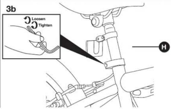
text_image
3b Loosen Tighten H3a Insert the Seat Post and Saddle

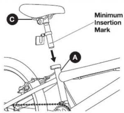
WARNING! When assembling the seat post, make sure it is inserted beyond the minimum insert mark. Failure to observe this warning may lead to a potentially unstable seat post and may result in serous personal injury.
Insert the lower end of the seat post and saddle C into the seat tube of the bike A
3b Securing the Seat Post
Tighten the clamp with the hexagonal key provided. Ensure saddle is tightly in position.
text_image
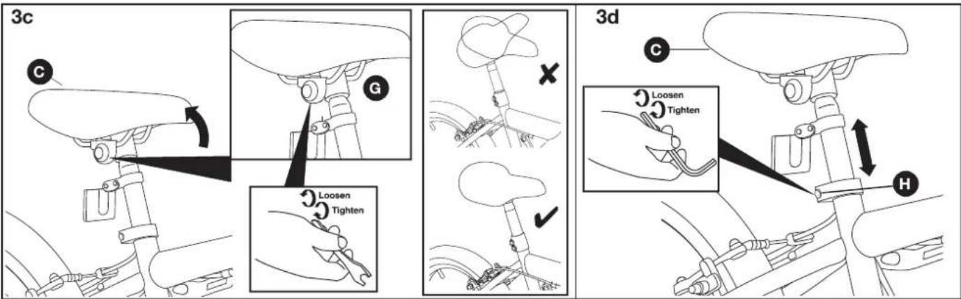
3c C G Loosen Tighten 3d C Loosen Tighten H3c Adjusting the Position of the Saddle
The angle of the saddle Ⓐ should be adjusted so that it is horizontal to the floor. To adjust the tilt of the saddle, loosen the saddle clamp nuts Ⓖ a quarter of a turn at a time using the multi tool supplied until the saddle can be moved.
If required, the saddle C can be moved forwards or backwards on the seat post while the saddle clamp nuts G are loose.
Once the saddle C is positioned correctly, retighten the saddle clamp nuts (G).
3d Adjusting the Height of the Saddle
The height of the saddle C should be adjusted so that the Rider can comfortably touch the ground with both feet. To adjust the height of the saddle C, loosen the seat post clamp H until the seat post can move freely H.

WARNING! When assembling the seat post, make sure it is inserted beyond the minimum insert mark. Failure to observe this warning may lead to a potentially unstable seat post and may result in serous personal injury.
Step 4
text_image
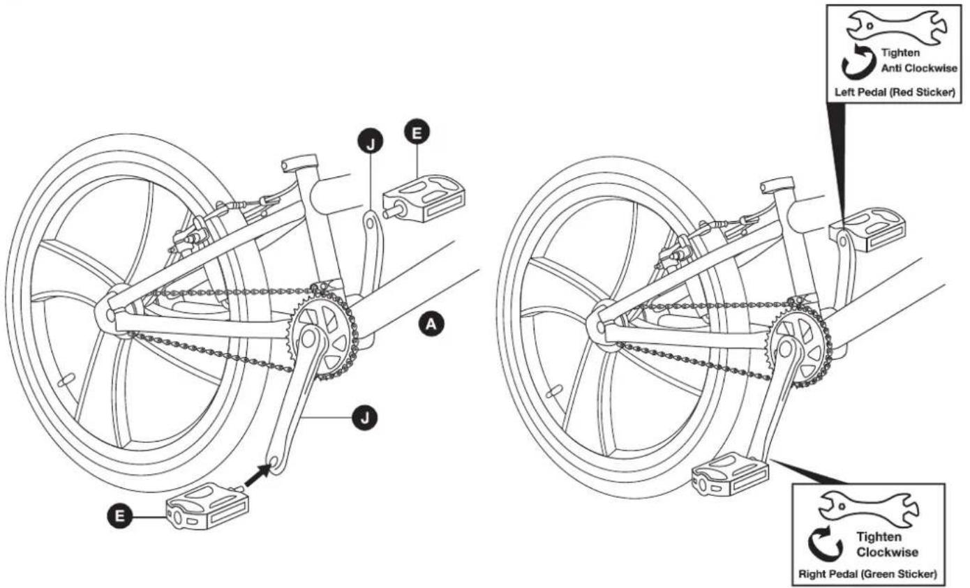
J E A J E Tighten Anti Clockwise Left Pedal (Red Sticker) Tighten Clockwise Right Pedal (Green Sticker)* THERE MAY BE SLIGHT VARIATIONS BETWEEN DRAWING AND ACTUAL COMPONENTS.

NOTE! The pedals E and crank arms J have colour coded stickers to indicate which pedal E matches which crank arm J.
NOTE! The threads on the left and right pedals are different. To prevent damage to the threads, only tighten the pedals in the direction indicated on the stickers.
4a Fitting the Right Hand Pedal
Locate the right hand pedal E. This will have a green sticker attached.
Locate the right hand crank arm ⚠ on the bike Ⓐ. This will also have a green sicker attached.
Remove the sticker from the right hand pedal E.
Insert the threaded shaft of the right hand pedal E into the threaded hole of the right hand crank arm J. Initially tighten the pedal using only your fingers in the direction indicated on the colour coded stickers. Fully tighten using the multitool supplied.
4b Fitting the Left Hand Pedal
Locate the left hand pedal E. This will have a red sticker attached.
Locate the left hand crank arm ⚠ on the bike ⚠. This will also have a red sticker attached.
Remove the sticker from the left hand pedal E.
Insert the threaded shaft of the left hand pedal E into the threaded hole of the left hand crank arm J. Initially tighten the pedal using only your fingers in the direction indicated on the colour coded stickers. Fully tighten using the multitool supplied.
Step 5
5a
text_image
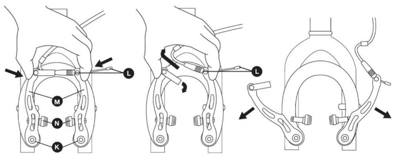
Technical diagram illustrating three different mechanical clamp configurations with labeled parts (M, N, K) and directional arrows indicating movement.* THERE MAY BE SLIGHT VARIATIONS BETWEEN DRAWING AND ACTUAL COMPONENTS.
5a Disconnect the Front Brake
Before the front wheel D can be installed, the front brake K must be disconnected. This allows the front tyre D to pass between the brake pads N during assembly.
Squeeze the two arms M of the front brake K together with one hand.
Using your other hand, pull the guide pipe and cable Ⓛ across and up to release it from the right hand arm.
Step 5 (continued)
text_image
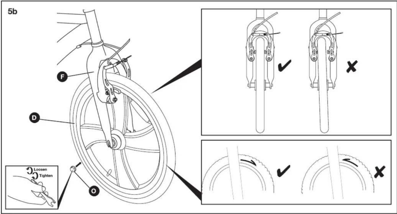
5b F D O Loosen Tighten5b Insert the Wheel
Loosen the wheel nuts Ⓐ on both ends of the front wheel Ⓓ axle.
Insert the axle of the front wheel D into the slots at the bottom of the forks F.

NOTE! The tyres may have a 'Direction of Rotation' arrow embossed on the side. When the front wheel D is assembled, the arrow should be pointing in the direction that the wheel will rotate.
While ensuring the wheel is centralised in the forks F, fully tighten the wheel nuts O using the supplied multitool.
Step 5 (continued)
5c
text_image
Technical diagram showing three different mechanical assembly states with labeled parts (L, M, K, D) and directional arrows indicating movement or assembly.* THERE MAY BE SLIGHT VARIATIONS BETWEEN DRAWING AND ACTUAL COMPONENTS.
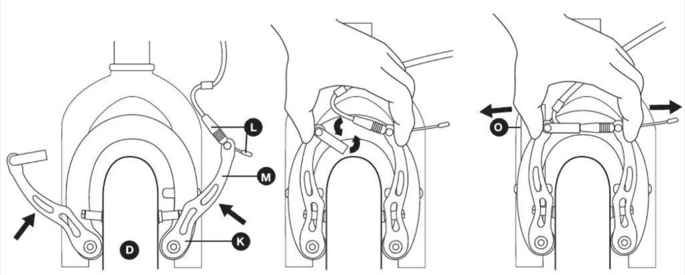
5c Refit the Front Brake
Squeeze the two arms M of the front brake K together with one hand.
Using your other hand, locate the guide pipe and cable ⏻ into retaining plate slot of the right hand arm.
Once the guide pipe and cable L is located, release the pressure on the two arms M.
Check that the front wheel Ⓓ rotates freely. If it does not, the front wheel Ⓓ may not be located centrally between the suspension forks Ⓞ. Alternatively, the front brakes may need adjusting. Please refer to the supplied Maintenance Manual.
Step 6
text_image
Diagram of a bicycle with labeled parts including 'Loosen' and 'Tighten' tools, showing bicycle structure and usage instructions.6 Inflate the Front and Rear Tyres

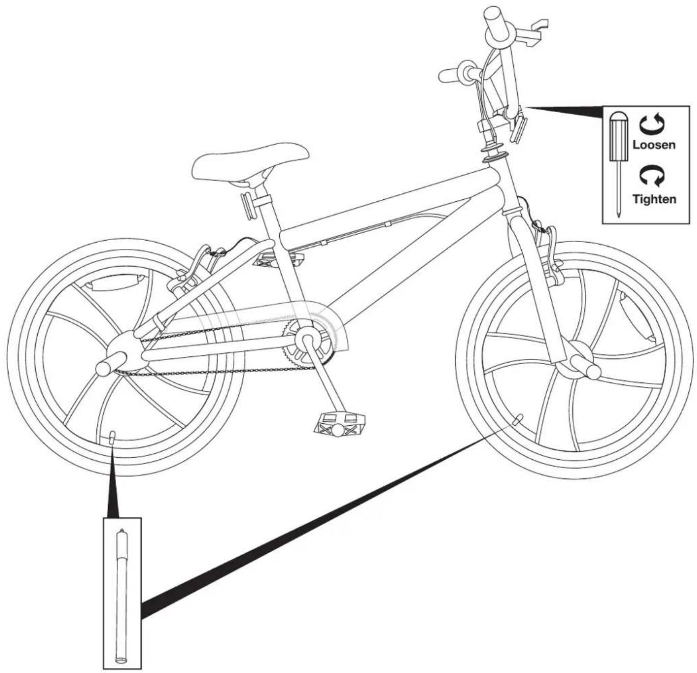
WARNING! The front and rear tyres must be fully inflated before attempting to ride the bike.
Under no circumstances should the tyres be inflated above the maximum pressure stated on the side of the tyres.
WARNING! Only inflate the front and rear tyres using a bicycle pump. Do not attempt to use another type of pump to inflate the tyres.
Before riding the bike, the front and rear tyres must be fully inflated to the pressures indicated on the side of the tyre.
Step 7
text_image
*THERE MAY BE SLIGHT VARIATIONS BETWEEN DRAWING AND ACTUAL COMPONENTS.7a Attaching the brake cables
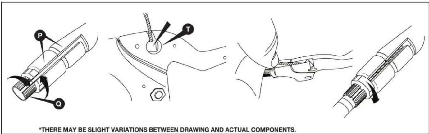
Align the slots in the barrel adjuster and adjuster lock ring with the slot in the front of the brake lever. Find the metal bead at the end of the brake cable, then slide this into the circular hole in the brake lever.

IMPORTANT: The right brake lever should operate the front brake.
Once the cable end is secured in position in the circular hole on the underside of the brake lever the cable should be inserted into the aligned slots on the lever, barrel adjuster lock and barrel adjuster.

Note: For the purpose of this manual the images show the brake levers from the underneath.
Next slide the cable housing over the cable and insert it into the open end of the barrel adjuster.
Finally turn the barrel adjuster bolt and barrel adjuster lock ring so that the cable is securely enclosed within the lever mechanism.
Step 7 (continued)
natural_image
Technical line drawing of a mechanical device with tripod base and central component (no text or symbols)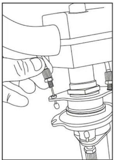
natural_image
Line drawing of a hand using a tool to adjust or install a mechanical component (no text or symbols present)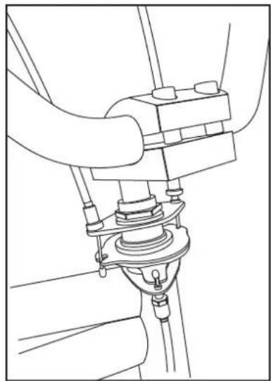
natural_image
Technical line drawing of a mechanical assembly with no visible text or symbols* THERE MAY BE SLIGHT VARIATIONS BETWEEN DRAWING AND ACTUAL COMPONENTS.
7b Attaching the Gyro

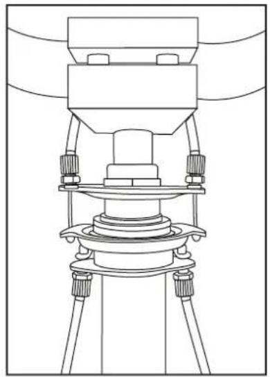
NOTE! There are two different length of rear brake cable for attaching the gyro. The shorter cable for left hand side of gyro (When sitting on the bike).
1 Locate the two rear brake cable ends (with metal beads). Insert the beads through the holes on either side of the base of the stem. There is a barrel adjuster bolt at the end of each cable's housing. Thread this into the threaded hole that the cable was inserted into.
2 Once the barrel adjuster bolts are secure, lift the top connector plate and hook the cable ends into the slot. There are two slots: one for each cable end.
3 Once set up the gyro mechanism should look like the example. Remember to test the brakes before riding.
Step 8
text_image
Threaded End Insert Screw Driver Into These Holes.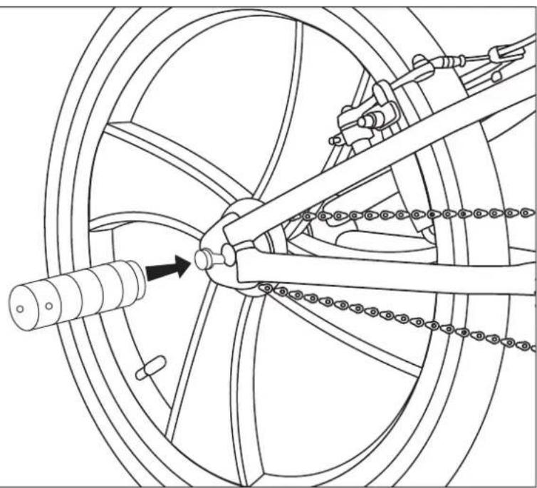
natural_image
Technical line drawing of a bicycle wheel assembly with linkage mechanism (no text or symbols)8 Peg Attachment.

NOTE!
Ensure that the wheels are securely attached.
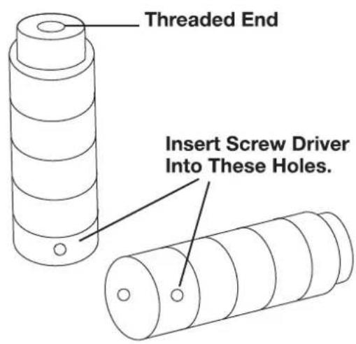
Thread the axle pegs onto the threaded end of the axle and tighten until secure using a screwdriver for extra leverage.
Before Riding
You should perform the following checks before riding your bike to ensure it is safe to use and operating correctly.
1. Is the Saddle Secure?
While standing next to the bike, try and move the saddle from side to side. If the saddle moves you should retighten the seat post bolt or the saddle clamp nuts.
2. Are the Front and Rear Tyres Inflated Correctly?
Squeeze the sides of the front and rear tyres. If they are soft they will need inflating. Re-inflate to the pressure indicated on the sides of the tyres using an approved bicycle pump.
3. Are the Pedals Tight?
Using the supplied multitool, ensure both the left and right pedals are fully tight. Remember that the threaded shafts of the left and right pedals tighten in different directions.
4. Do the Brakes Work?
Stand next to the bike and apply the front brake and push forwards. If the wheels move, the front brake may not be working correctly. If required, adjust the front brake as described in the Maintenance Manual.
Repeat the above check for the rear brake.
5. Do the Handlebars Move?
Hold the front wheel between your legs and try to move the handlebars. If the handlebars move, the stem bolt may have become loose. Retighten the stem bolt.
6. Is the Bike Clean?
The bike should be cleaned and re-oiled regularly to ensure it operates correctly.
Using the Brakes
The bike is fitted with front and rear brakes to stop the bike effectively.
The brakes are operated using two brake levers mounted on the handle bars. The left hand brake lever operates the rear brake and the right hand brake lever operates the front brake.
Riding Using Personal Music Players
It is recommended that personal music players are not used while riding a bike. These devices prevent you from hearing approaching vehicles and may prove to be a distraction.
Riding in Bad Weather

WARNING! Always take extra care when riding in wet, foggy, windy or icy conditions. The brakes may not be as effective and the braking distances may be increased.
When riding in bad weather i.e. wet, foggy, windy or icy, always wear bright, reflective clothing which is warm and waterproof.
You should always give other road users clear signals in plenty of time particularly when approaching junctions. Always brake earlier than you would in the dry as the required braking distance will be increased.
Be aware that all types of surface become greasy or slippery in bad weather. Do not turn or brake suddenly.
Riding in the Dark

WARNING! When riding in the dark, always make sure that the bike is fitted with suitable reflectors and a white front light and a red rear light.
It is essential that other road users can clearly see you when riding in the dark. Always wear bright, reflective clothing. Suitable reflectors should be fitted to the front and rear of the bike and if possible the wheels. A white light must be fitted to the front of the bike and a red light at the rear.
Before starting any journey in the dark or even twilight, ensure the lights are working correctly and are turned on.
Clean lights and reflectors regularly and make sure they can be seen from a distance.
Adjusting V-Brakes
Throughout the life of your bike, the front v-brake may need adjusting if the brake cable has stretched or the brake arms have been knocked during use.
Adjusting V-Brake Cable Tension
1a
text_image
Technical diagram illustrating bicycle clamp tooling and adjustment, showing steps from locking to widening 2mm measurements.* THERE MAY BE SLIGHT VARIATIONS BETWEEN DRAWING AND ACTUAL COMPONENTS.
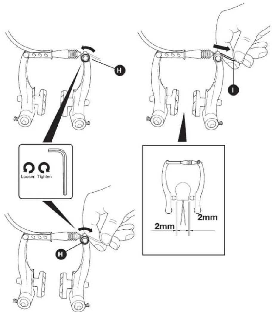
1a. Adjust the Brake Cable
The brake cable must be adjusted to ensure that the brakes are as close as possible to the wheel rim when no pressure is applied to the brake lever.
Using a suitable spanner or socket, loosen the cable pinch bolt Ⓗ until the brake cable ⏻ is free to move.
Pull the brake cable 1 until the brake pads are approximately 2mm/0.16"inch from the wheel rim.
Retighten the cable pinch bolt ⚠ while holding the brake cable in position.
Adjusting V-Brake Cable Tension (continued)
text_image
Technical diagram of a mechanical device with labeled parts J and I, showing a cable joint and connector.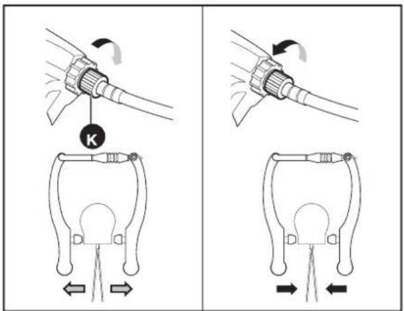
text_image
Technical diagram showing two mechanical assembly steps with labeled components and directional arrows indicating motion or movement.* THERE MAY BE SLIGHT VARIATIONS BETWEEN DRAWING AND ACTUAL COMPONENTS.
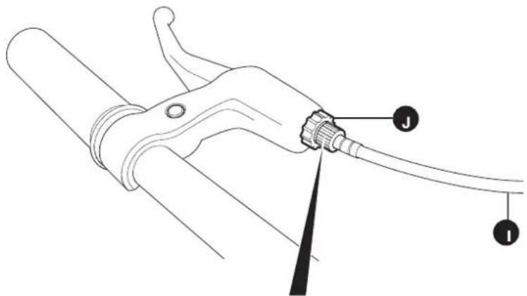
1b. Fine Tune the Cable Tension
If the brake pads are too close or too far away from the wheel rim once the brake cable has been adjusted in step 1a, fine tune the cable tension as described below.
Unscrew the barrel adjuster locking nut ⚠ by turning it anti-clockwise.
Turn the barrel adjuster bolt to increase or decrease the cable tension. This will fine tune the position of the brakes.
- To increase the tension on the brake cable and move the brakes towards the wheel rim, turn the barrel adjuster bolt K anti-clockwise.
- To decrease the tension on the brake cable ① and move the brakes away from the wheel rim, turn the barrel adjuster bolt ② clockwise.
Once the cable tension is correct, retighten the barrel adjuster locking nut ⚡.
Adjusting V-Brake Spring Tension
text_image
1a &1b L N M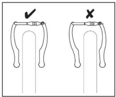
text_image
Diagram showing correct and incorrect states of a mechanical component, with checkmark indicating downward adjustment and X mark indicating horizontal adjustment.* THERE MAY BE SLIGHT VARIATIONS BETWEEN DRAWING AND ACTUAL COMPONENTS.
1b. Fine Tune the Cable Tension
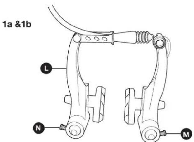
Over time, the brake arms can begin to lean to one side, making the distance between the brake pads and the wheel rim uneven. This can be corrected by adjusting the spring tension of the individual brake arm.

NOTE! When adjusting the spring tension, even adjustments should be made to both brake arms until they are positioned evenly on either side of the wheel and rim.
1a. Adjusting the Spring Tension on the Right Hand Brake Arm.
If the brake arms L lean to the right (when viewed from the front of the bike), the right hand brake arm spring tension should be reduced. This can be achieved by turning the right spring tension screw M anti-clockwise.
If the brake arms L lean to the left (when viewed from the front of the bike), the right hand brake arm spring tension should be increased. This can be achieved by turning the right spring tension screw M clockwise.
1b. Adjusting the Spring Tension on the Left Hand Brake Arm.
If the brake arms L lean to the right (when viewed from the front of the bike), the left hand brake arm spring tension should be increased. This can be achieved by turning the left spring tension screw N clockwise.
If the brake arms L lean to the left (when viewed from the front of the bike), the left hand brake arm spring tension should be decreased. This can be achieved by turning the left spring tension screw N anti-clockwise.
Adjusting U-Brake
text_image
Mount Points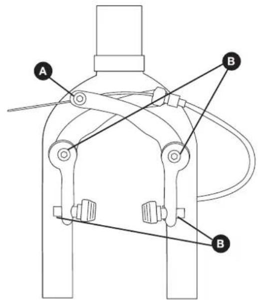
text_image
Technical diagram of a mechanical device with labeled components A and B, showing connections and structural details.* THERE MAY BE SLIGHT VARIATIONS BETWEEN DRAWING AND ACTUAL COMPONENTS.
U Brakes
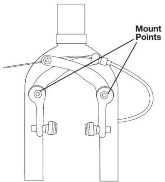
These are the most common form of brakes found on BMX bikes. U-Brakes consist of two arms which are mounted to two points that are spring-loaded and cross each other above the tyre. When the lever is pulled the arms pivot about the mount points
1. Adjust the Cable Tension
Loosen the cable pinch bolt and pull or release the cable slightly.
2. Adjust Brake Arm Balance
Using a flat spanner and allen key, adjust the outer part of the brake arm mount bolts until the arms are balanced. The brake pads should be the same distance from the rim, and should return to the same point when released.
3. Brake Pads
Ensure the brake pads are aligned correctly with the rim.
Routine Maintenance
Lubrication Information
| Frequency | Component | Lubricant | How to Lubricate |
| Weekly | ChainDeraileur wheelsDeraileursBrake calipersBrake levers | Chain lube or light oilChain lube or light oilOilOilOil | Brush on or squirtBrush on or squirtOil can3 drops from oil can2 drops from oil can |
| Monthly | Shift levers | Lithium based grease | Disassemble |
| Every Six Months | FreewheelBrake cables | OilLithium based greas | 2 squirts from oil canDisassemble |
| Yearly | Bottom bracketPedalsDeraileur cablesWheel bearingsHeadsetSeat pillar | Lithium based greasLithium based greasLithium based greasLithium based greasLithium based greasLithium based greas | DisassembleDisassembleDisassembleDisassembleDisassembleDisassembleDisassemble |
NOTE: The frequency of maintenance should increase with use in wet or dusty conditions. Do not over lubricate-remove excess lubricant to prevent dirt build up. Never use a degreaser to lubricate your chain(WD-40 ^TM ).
WARNING: Do not over lubricate. If lubricant gets on rims, tires or brake shoes, it will reduce control and braking performance and may require a longer stopping distance. Injury to the rider can occur. Avoid getting any excess lubrication on these area by wiping off excess lubricant, and keeping these areas clean and dry.
Chain Tension
natural_image
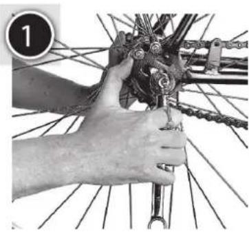
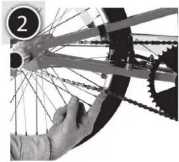
Close-up of hands assembling a bicycle wheel assembly (no visible text or symbols)Pull the wheel back until the chain is taut, then tighten the wheel nuts with your fingers. The chain should have about half an inch of slack and the wheel must be centred in the frame.
Then tighten the wheel nuts half a turn at a time each.
natural_image
Close-up of a bicycle wheel with chains and gears, no visible text or symbolsOnce the hub nuts are tight, check that you can only lift the chain about half an inch. And also that the wheel is exactly in the centre of the frame. Tighten the hub nuts for the last time, reconnect the gear cable and adjust.
Note: The chain is automatically tensioned on models fitted with derailleur gears.
natural_image
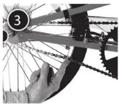
Close-up of a bicycle wheel with chains and gears, hands adjusting the components (no visible text or symbols)Lift the chain at the mid-point of it's bottom run. Chain tension is correct when you can lift it 12mm. To adjust, undo the wheel nuts, move the wheel to it's new position, check it's central and finally, tighten the wheel nuts a little at a time.