X401H - Drohne MJX - Kostenlose Bedienungsanleitung
Finden Sie kostenlos die Bedienungsanleitung des Geräts X401H MJX als PDF.


Benutzerfragen zu X401H MJX
0 Frage zu diesem Gerät. Beantworten Sie die, die Sie kennen, oder stellen Sie Ihre eigene.
Eine neue Frage zu diesem Gerät stellen
Laden Sie die Anleitung für Ihr Drohne kostenlos im PDF-Format! Finden Sie Ihr Handbuch X401H - MJX und nehmen Sie Ihr elektronisches Gerät wieder in die Hand. Auf dieser Seite sind alle Dokumente veröffentlicht, die für die Verwendung Ihres Geräts notwendig sind. X401H von der Marke MJX.
BEDIENUNGSANLEITUNG X401H MJX
X-SERIES FPV REAL-TIME HD IMAGES TRANSMISS
MOBILE PHONE APP CONTROL BAROMETER HOLD ALTITUDE & ONE KEY START/LANDING
FPV REAL-TIME HD IMAGES TRANSMISSION 6-AXIS GYRO QUDCOPTER
natural_image
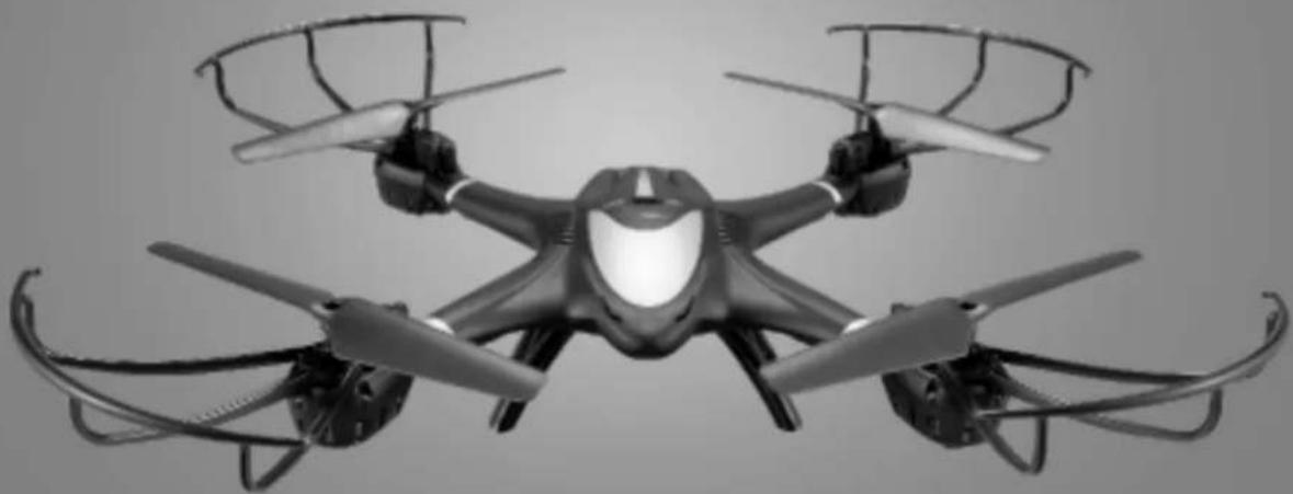
Black-and-white photo of a quadcopter drone with extended wings and propellers (no text or symbols visible)INSTRUCTION MANUAL
Technical parameter of the model
Fuselage Length:298mm
Gross Weight: about 128g
Motor: Coreless motor
Overall Height: 76mm
Battery: Li-polymer 7.4V 350mAh
Main Rotor Diameter: 135mm
Charging Time: about 90 minutes
Introduction
- Quad-rotor design insures more stable and powerful performance and make all kinds of 3D action more easier.
- Headless mode and one key return are available.
- New designed structure makes assembly and maintenance easier.
- Adopting 2.4G auto connection technology, scores of model can be played at the same time.
- Equipped with the newest 6-axis gyro control system, this model has the characteristics of stable flight and easy operation.
●Full charged battery can support 7.5 minutes steady flight. - New functions increased are altitude-hold mode, one key start/landing and mobile phone APP control.
Product/spare parts included in this packaging
| Description | QTY (pc) | Description | QTY (pc) | Description | QTY (pc) |
| Model | 1 | Propeller | 4 | Screw | 4 |
| Remote Controller | 1 | Landing Gear | 2 | Screwdriver | 1 |
| Manual | 1 | Protecting Guard | 4 | USB Charging Cable | 1 |
| Camera | 1 | Mobile Phone Holder | 1 |
Thank you for purchasing this product. Please read this manual carefully before use and retain it for future reference.
Safety guidelines
- This product is not a toy. It is not applicable for children who are under 14 years old.
- Please read this instruction manual carefully before playing and operate the product according to the manual.
- The users are in full charge of proper operating the model. The manufacturer and dealers disclaim all responsibility for the damage caused by misuse.
- Keep the small accessories away from the kids to avoid accident.
- Keep batteries away from fire or high temperature environment.
- When flying the model, keep it 1\~2 meters away from user or others to avoid injury due to collision.
- Not to decompose or modify the product which may cause malfunction or accident.
- Fly the model within your eye vision for easy and safety control.
- Need adult supervision when this model is being played by children.
- Only batteries of the same or equivalent type as recommended are to be used.
- Insert batteries with correct polarity.
- Non rechargeable batteries are not to be charged; the transmitter need 4 X AA batteries for work.
- Do not mix old and new batteries.
- Do not mix alkaline, standard(carbon-zinc), or rechargeable(nickel-cadmium) batteries.
- Rechargeable batteries are to be removed from the toy before being charged;
- Rechargeable batteries are only to be charged under adult supervision;
●Exhausted batteries are to be removed from the toy; - The supply terminals are not to be short-circuited.
- The USB charing line to be used with the product should be regularly examined for potential hazard, such as damage to the cable or cord, plug, enclosure of other parts and that in the event of such damage, the product must not be used until that damage had been properly removed.
The LCD remote controller
Main features of the remote controller
- Adopt microcomputer control remote controller system and 2.4G auto connection technology, scores of copters can be played at the same time without any interference.
- Control the function of upward, downward, forward, backward, leftward, rightward, turn left, turn right and 3D flips & roll of the copter.
- Throttle control stick can be freely switched according to player's habit.
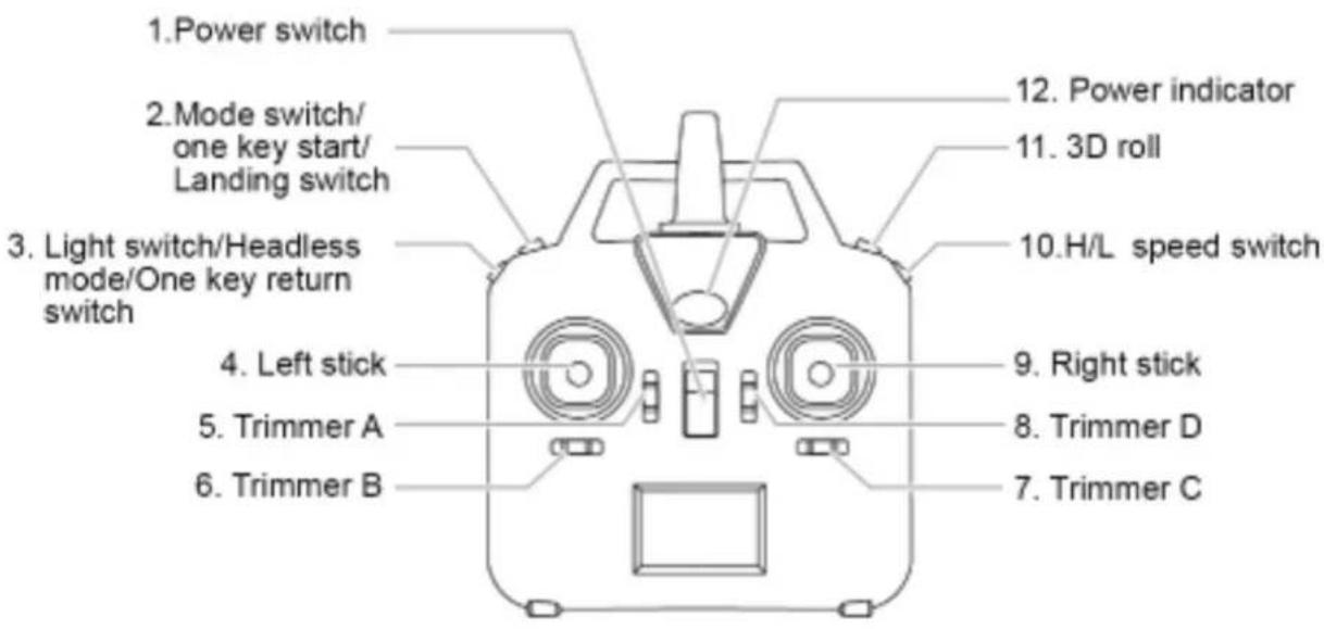
Sketch and function switches of the remote controller
text_image
1. Power switch 2. Mode switch/ one key start/ Landing switch 3. Light switch/Headless mode/One key return switch 4. Left stick 5. Trimmer A 6. Trimmer B 12. Power indicator 11. 3D roll 10.H/L speed switch 9. Right stick 8. Trimmer D 7. Trimmer CRemote Controller(Transmitter)
| No. | Function switch | Function description |
| 1 | Power switch | It controls the power source of the transmitter.Slide the power switch to the “ON” position, the transmitter is powered on; slide the power switch to the “OFF” position, the transmitter is powered off. |
| 2 | Mode switch/One key start / Landing switch | 1.Long-press to change the throttle control stick.2.Short-press to start/land to the ground. |
Note: a) Changes or modifications not expressly approved by the party responsible for compliance could void the user's authority to operate the equipment.
b) This equipment has been tested and found to comply with the limits for a Class B digital device, pursuant to part 15 of the FCC Rules. These limits are designed to provide reasonable protection against harmful interference in a residential installation. This equipment generates, uses and can radiate radio frequency energy and, if not installed and used in accordance with the instructions, may cause harmful interference to radio communications. However, there is no guarantee that interference will not occur in a particular installation. If this equipment does cause harmful interference to radio or television reception, which can be determined by turning the equipment off and on, the user is encouraged to try to correct the interference by one or more of the following measures:
—Reorient or relocate the receiving antenna.
—Increase the separation between the equipment and receiver.
—Connect the equipment into an outlet on a circuit different from that to which the receiver is connected.
—Consult the dealer or an experienced radio/TV technician for help.
| No. | Function switch | Function description |
| 3 | Light switch/Headless mode/One key return switch | 1.This is the light switch of the model. Press it once to turn on the light and press it once again to turn off the light.2.Headless mode on-off button: Press this button for about 2 seconds, the remote control will send out 2 beep sounds and letters "stick mod" will be flashing on the LCD screen, the indicator light of the model turns from constant "on" to "flashing", then, the model is in the headless mode. Press this button again for about 2 seconds, the remote control will send out 2 beep sounds and "stick mod" keeps constant "on", indicator light of the model turns from flashing to constant "on", then, the model exit headless mode.3.When the model is flying in headless mode, press one key return button, the model will fly towards player.Press the one key return button again or operate the forward/backward control stick, the model will exit the one key return function. |
| 4 | Left stick | STICK MODE 2:upward/downward,turn left/turn right;STICK MODE 4:upward/downward,leftward/rightward.STICK MODE 1:forward/backward,turn left/turn right;STICK MODE 3:forward/backward,leftward/rightward. |
| 5 | Trimmer A | In stick Mode 2 and 4, this button is null.In stick Mode 1 and 3, it helps to tune the model's forward and backward flight. |
| 6 | Trimmer B | In stick Mode 3 and 4, it helps to tune the model's sideward flight.In stick Mode 1 and 2,it helps to tune the model's left and right direction turning speed. |
| 7 | Trimmer C | In stick Mode 3 and 4, it helps to tune the model's left and right direction turning speed.In stick Mode 1 and 2,it helps to tune the model's sideward flight. |
| 8 | Trimmer D | In stick Mode 1 and 3, this button is null.In stick Mode 2 and 4, it helps to tune the model's forward and backward flight. |
| 9 | Right stick | STICK MODE 1: upward/downward,leftward/rightward;STICK MODE 3: upward/downward, turn left/turn right;STICK MODE 2: forward/backward,leftward/rightward;STICK MODE 4: forward/backward,turn left/turn right. |
| 10 | H/L speed switch | There are 2 flight modes of the model: low speed and high speed. |
| 11 | 3D roll | Keep pressing the 3D rolling button and push the forward/backward and the leftward/rightward control stick to the edges to perform the roll actions accordingly. |
| 12 | Power indicator | The indicator light keeps blinking slowly: the transmitter is not activated.The indicator light keeps flashing rapidly: the transmitter is sending out connection signal to the model.The indicator light keeps on without blinking: the transmitter is ready for controlling the flight. |
How to install the battery of remote controller
natural_image
Pure mechanical diagram showing a rotating component with no text or symbolsPic.1
natural_image
Diagram of a battery pack connected to four batteries, showing internal structure and charge distribution (no text or labels)Pic.2
natural_image
Diagram of a mechanical device with a rotating arrow indicating rotation (no text or symbols)Pic.3
How to remove and insert batteries.
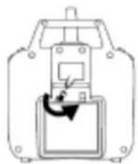
- Unscrew counter clockwise to open the battery compartment cover. (Pic.1)
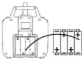
- Install 4 X AA batteries into the battery compartment according to the given polarity. (Pic. 2)
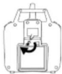
- Screw clockwise to close the battery compartment. (Pic. 3)
4 modes switches
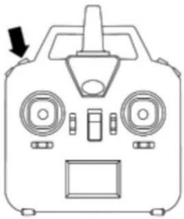
Long-press the mode switch button to choose mode 2/ mode 4/ mode 1/mode 3.
natural_image
Front view diagram of a control device with no visible text or symbolsStick mode selection
text_image
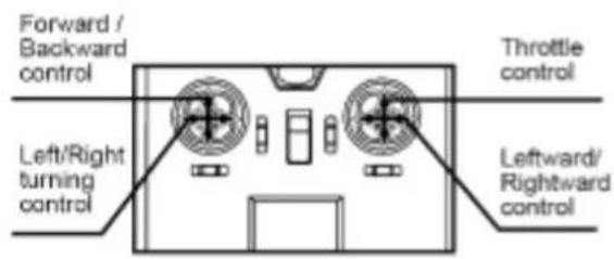
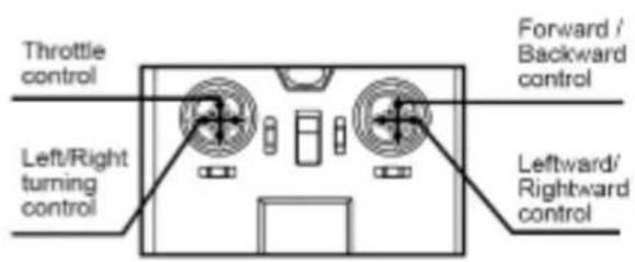
Forward / Backward control Throttle control Left/Right turning control Leftward/ Rightward controlSTICK MODE:1
text_image
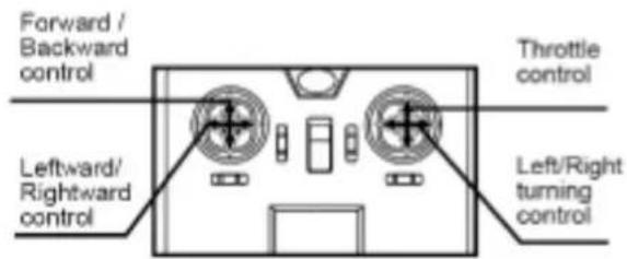
Throttle control Left/Right turning control Forward / Backward control Leftward/ Rightward controlSTICK MODE:2
text_image
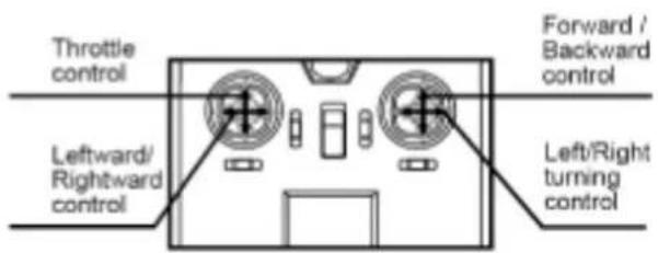
Forward / Backward control Throttle control Leftward/ Rightward control Left/Right turning controlSTICK MODE:3
text_image
Throttle control Forward / Backward control Leftward/ Rightward control Left/Right turning controlSTICK MODE:4
Flight speed selection
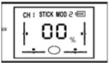
There are 2 flight speeds available: low speed and high speed. Player can select the flight speed by pressing the H/L speed button.
text_image
CH : STICK MOD 2 00 %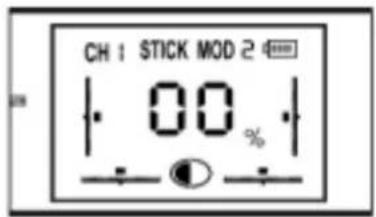
text_image
CH 1 STICK MOD 2 00 %The model
Major parts of the model
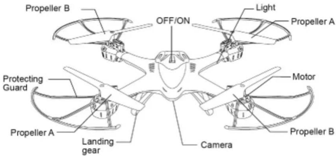
text_image
Propeller B OFF/ON Light Propeller A Protecting Guard Motor Propeller A Landing gear Camera Propeller BProtection frame and landing gear installation
natural_image
Close-up of a mechanical component with wires and a highlighted section (no visible text or symbols)Pic.4
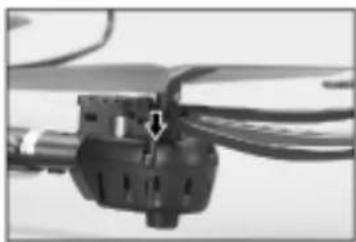
- There are 3 interfaces on each motor cabinet. Insert the frame plugs into the interfaces and fix it. (Pic.4)
natural_image
Close-up of a helicopter's propeller with visible blades and mounting base (no text or symbols)Pic.5
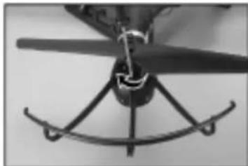
- Fix the protection frame by screwing clockwise. (Pic.5)
natural_image
Close-up of a mechanical component with two protruding blades and a central base (no visible text or symbols)Pic.6
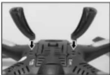
3.There are 4 interfaces at the bottom of the model, insert the landing gear plugs into the interfaces and fix it. The landing gear is trapezoid, make sure that the longer waist of the trapezoid is point to the direction of the model's nose. (Pic.6)
How to change new battery for the model
natural_image
Close-up of a mechanical component with a tool inserted, showing a circular hole and an arrow indicating direction (no text or symbols visible)Pic.7
natural_image
Close-up of hands holding a small object with arrows indicating direction (no visible text or symbols)Pic.8
natural_image
Close-up of hands using a tool to adjust or install a small component with an arrow (no visible text or symbols)Pic.9
natural_image
Close-up of a hand pressing a small electronic component with an arrow pointing to it (no visible text or symbols)Pic.10
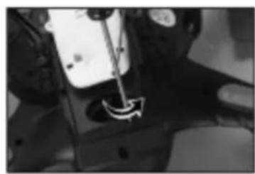
1.Open the battery door by screwing counter-clockwise.(Pic.7)
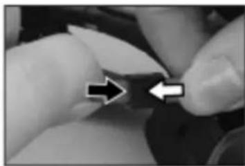
2. Unplug the battery wire from the power wire plug of the model and take out the battery.(Pic.8)
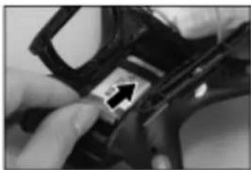
3. Plug the new battery wire into the power wire plug of the model and insert the battery into the battery compartment.(Pic.9)
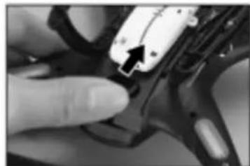
4. Close the battery door and fasten it by screwing clockwise.(Pic.10)
The method of the aircraft battery charging
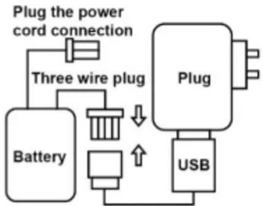
Off the switch, Plug the battery from the power line which connect the jack-plug. The charging plug of USB charging is connected to the three-wire plug on the battery. When charging, USB charger indicator light. When the battery is fully charged, The LED of the USB charger off. The charging time about 90 minute.
flowchart
graph TD
    A["Plug the power cord connection"] --> B["Three wire plug"]
    B --> C["Battery"]
    B --> D["USB"]
    C --> E["Plug"]
    D --> E
    E --> F["Output"]
NOTE: Battery should be full charged before storing.
Preparation for flight
The remote control
- Recheck the playground; be sure that it is free from crowd, animals and other barrier.
- Slide down the throttle control stick to the bottom.
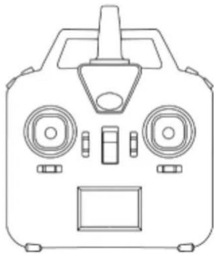
- Turn on the remote controller and the power indicator light flashes rapidly and sends out connetional signal to the drone.
- Slide the throttle control stick up to the top; then, return the throttle control stick to the bottom; It will take about 10 seconds to finish the signal connection process.
Once signal connection is completed, the power light will stay "on" without blinking and the remote controller is set for flight.
natural_image
Line drawing of a control panel with dual speakers and display (no text or symbols)The model
- Make sure that the battery (at the bottom of the model) is well installed and connected with power wire of model. The model is OFF.
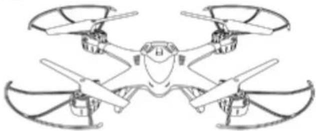
- Turn on the model; the flash light will keep flashing quickly, the gyro of the model will be in signal detecting
condition. Set the model to flat surface, about 4 seconds later, the flash light will keep constant "ON". It means that signal connection is finished and the model is ready for flight.
natural_image
Line drawing of a multi-rotor drone with four wings and a central body (no text or symbols)- To ensure steady flight, please set the value of the Trimmer to the midpoint.
- Push up the throttle stick slowly and the model takes off.
- To avoid any misunderstanding, we have defined the orientation of the model as follows: The model is set to be copter nose right ahead and tail facing the player. The copter nose direction is named as "forward", the tail direction is named as "backward". The copter flies up to the sky is named as "upward"; the copter flies down to the ground is named as "downward". Player's left side is named as "left", player's right side is named as "right". All the directions we are talking about in this manual are subject to the definition above.
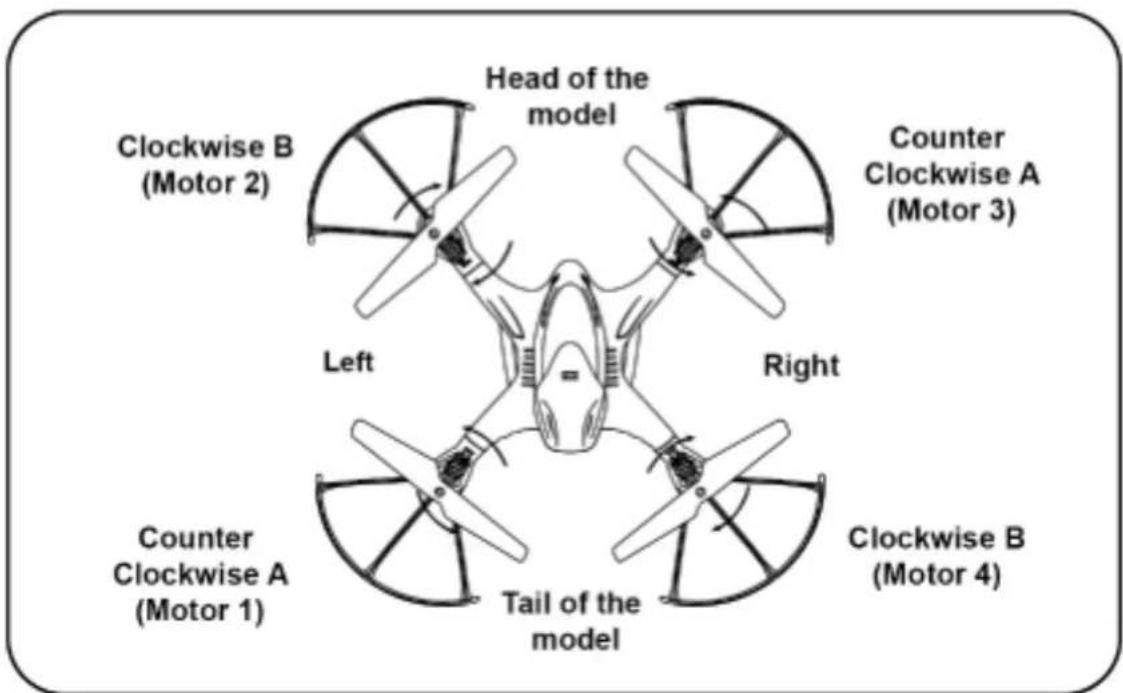
text_image
Clockwise B (Motor 2) Head of the model Counter Clockwise A (Motor 3) Left Right Counter Clockwise A (Motor 1) Tail of the model Clockwise B (Motor 4)- The blue lights are at the front of the model; the orange lights are at the back of the model.
- When the model is on, checking the rotation direction of the rotor blades; the front-left and right-back rotor blades should be rotating in clockwise direction; the right-front and left-back rotor blades should be rotating in counter-clockwise direction.
- If the model keeps flying to one side, it can be corrected by adjusting the trimmer on the remote control.
Remarks:
- Signal connection between the model and the remote control is required for the first use.
- Set the connection one by one to avoid signal connection error.
- To better protect the battery, please unplug the battery cable from the power wire after use.
Trimmer functions
- If the model keeps moving forward/backward even there is no control signal given, users may adjust the elevator trim to keep the model balanced.
STICK MODE 1 or 3:
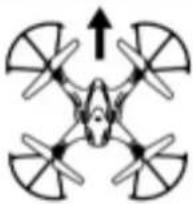 | If the model keeps moving forward, push down Trimmer A until it gains balance. |
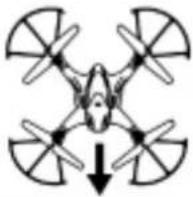 | If the model keeps moving backward, push up Trimmer A until it gains balance. |
STICK MODE 2 or 4:
 | If the model keeps moving forward, push down Trimmer D until it gains balance. |
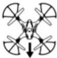 | If the model keeps moving backward, push up Trimmer D until it gains balance. |
- If the model keeps moving leftward/rightward even there is no control signal given, users may adjust the aileron trim to keep the model balanced.
STICK MODE 3 or 4:
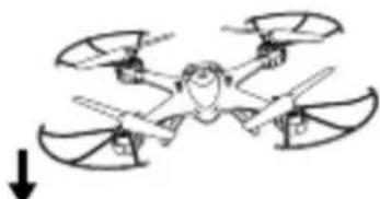 | If the model keeps moving leftward, turn right of Trimmer B until it gains balance. |
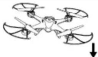 | If the model keeps moving rightward, turn left of Trimmer B until it gains balance. |
STICK MODE 1 or 2:
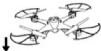 | If the model keeps moving leftward, turn right of Trimmer C until it gains balance. |
 | If the model keeps moving rightward, turn left of Trimmer C until it gains balance. |
- If the model keeps spinning even there is no control signal given, users may adjust the rudder trim to keep the model balanced.
STICK MODE 1 or 2:
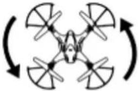 | If the model keeps spinning counterclockwise in the air, turn right of Trimmer B until it gains balance. |
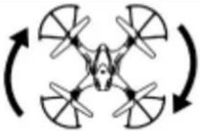 | If the model keeps spinning clockwise in the air, turn left of Trimmer B until it gains balance. |
STICK MODE 3 or 4:
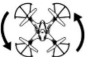 | If the model keeps spinning counterclockwise in the air,turn right of Trimmer C until it gains balance. |
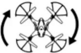 | If the model keeps spinning clockwise in the air,turn left of Trimmer C until it gains balance. |
Operating
| Upward | 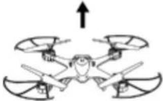 | Push up the throttle control stick, the rotation speeds of the mains rotors are increasing and the model ascends accordingly. |
| Altitude hold | Push up the throttle control stick, fly the drone to the expected height and release the throttle control stick. The drone will be hovering at this height. | |
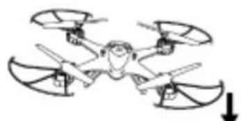
| Downward | 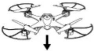 | Push down the throttle control stick, the rotation speeds of the mains rotors are decreasing and the model descends accordingly. |
| Turn left | 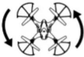 | Turn the left/right turning control stick to the left,the model will turn left. |
| Turn right | 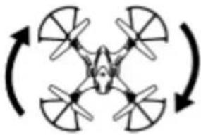 | Turn the left/right turning control stick to the right,the model will turn right. |
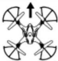
| Forward | 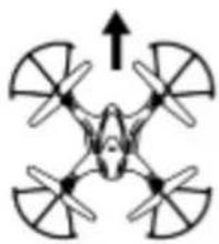 | When the model is flying, push up the forward/backward control stick, the model will move forward. |
| Backward | 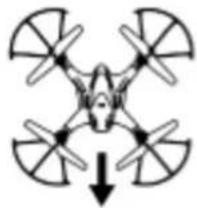 | When the model is flying, push down the forward/backward control stick, the model will move backward. |
| Leftward flight | 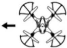 | Turn the sideward flight control stick to the left side,the model will fly leftward. |
| Rightward flight | 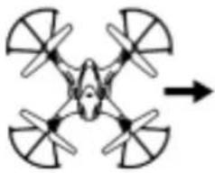 | Turn the sideward flight control stick to the right side,the model will fly rightward. |
Landing and emergency stop
Short-press the one key landing button or push the throttle control stick to make the drone gently land to the ground. About 2 seconds later, the drone will thoroughly stop flying.
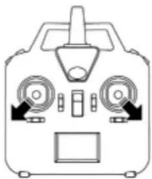
When the drone is flying less than 1 meter height from the ground, but you need to stop the drone urgently. Please turn the left control stick of the remote control to the left-bottom and right control stick to the right-bottom to cease the flying drone.
natural_image
Front view diagram of a control unit with dual motors and display (no text or symbols)3D Roll
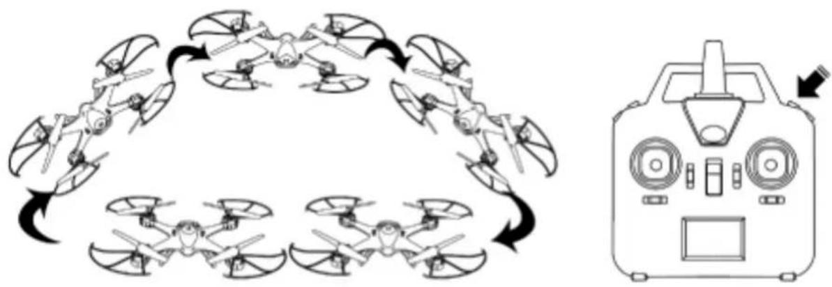
Keep pressing the 3D rolling button and push the forward/backward and the leftward/rightward control stick to the edges to perform the roll actions accordingly.
flowchart
graph TD
    A["Drone 1"] --> B["Drone 2"]
    B --> C["Drone 3"]
    C --> D["Drone 4"]
    D --> E["Drone 5"]
    E --> F["Drone 6"]
    F --> G["Drone 7"]
    G --> H["Drone 8"]
    H --> I["Drone 9"]
    I --> J["Drone 10"]
    J --> K["Drone 11"]
    K --> L["Drone 12"]
    L --> M["Drone 13"]
    M --> N["Drone 14"]
    N --> O["Drone 15"]
    O --> P["Drone 16"]
    P --> Q["Drone 17"]
    Q --> R["Drone 18"]
    R --> S["Drone 19"]
    S --> T["Drone 20"]
    T --> U["Drone 21"]
    U --> V["Drone 22"]
    V --> W["Drone 23"]
    W --> X["Drone 24"]
    X --> Y["Drone 25"]
    Y --> Z["Drone 26"]
    Z --> AA["Drone 27"]
    AA --> AB["Drone 28"]
    AB --> AC["Drone 29"]
    AC --> AD["Drone 30"]
    AD --> AE["Drone 31"]
    AE --> AF["Drone 32"]
    AF --> AG["Drone 33"]
    AG --> AH["Drone 34"]
    AH --> AI["Drone 35"]
    AI --> AJ["Drone 36"]
    AJ --> AK["Drone 37"]
    AK --> AL["Drone 38"]
    AL --> AM["Drone 39"]
    AM --> AN["Drone 40"]
    AN --> AO["Drone 41"]
    AO --> AP["Drone 42"]
    AP --> AQ["Drone 43"]
    AQ --> AR["Drone 44"]
    AR --> AS["Drone 45"]
    AS --> AT["Drone 46"]
    AT --> AU["Drone 47"]
    AU --> AV["Drone 48"]
    AV --> AW["Drone 49"]
    AW --> AX["Drone 50"]
Notes:
We suggest beginner choosing non-obstacles space and soft ground for playing.
Headless mode:
Enter into headless mode:
Once signal between the model and the remote control is successfully connected, press the function button located at top right of the remote control for 2 seconds. The remote control will send out two beep sounds and there will be letters of "stick mod" flashing on the LCD screen, the model's indicator light turns from constant "ON" to "flashing". That means the model is in headless mode.
Exit headless mode:
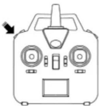
When the model is in headless mode, press the function button at top left of the remote control of 2 seconds, the remote control will send out 3 beep sounds and the letter "Stick mod" is keeping constant "on"; the model's indicator light turns from flashing to constant "on". That means the model has exited the headless mode.
natural_image
Front view diagram of a handheld device with front-mounted screens and a control panel (no text or symbols)Check up on the direction of the model in headless mode:
When the model is in headless mode, flight direction proof is needed. Set the head of the model ahead of the player, turn both of two control sticks to the lower right corner for about 2 seconds, the model's indicator light will turn from slowly flashing to quick flashing and flight direction proof is finished.
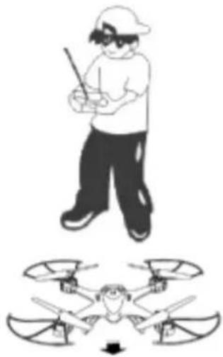
natural_image
Illustration of a person in a white hat holding a stick above a multi-colored drone with a person inside (no text or symbols)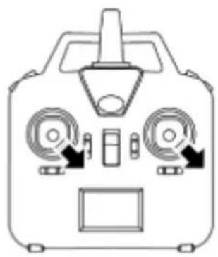
natural_image
Front view diagram of a control device with two motors and a central display (no text or symbols)Flight direction control in headless mode:
- When checking up on the flight direction of the model, set the model nose right ahead and tail facing the player's, at this time, the model's nose is pointing forward; this direction will be constantly considered as "forward" when forward signal is given from the remote control, no matter where the model nose is pointing to. That is to say, the player's straight front side is defined as "forward"; the player's back side is defined as "backward", the player's left side is defined as left; the player's right side is defined as right.
- When the model is flying in headless mode, player should keep facing the forward direction. Otherwise, the model will be out of control. The model control is showed as below:
| Push up the forward/backward control stick, the model will fly forward, away from player. |  | Turn right the sideward flight control stick, the model will fly to the right side of the player. |
| Push down the forward/backward control stick, the model will fly backward, towards player. | Turn right the turning control stick; the model will turn to the left side of the player. | |
| Turn left the sideward flight control stick; the model will fly to the left side of player. | 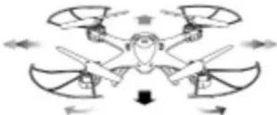 | Turn left the turning control stick; the model will turn to the right side of the player. |
One key return:
When the model is flying in headless mode, press one key return button, the model will fly towards player. Press the one key return button again or operate the forward /backward control stick, the model will exit the one key return function.
Remarks:
- Flight direction proof is needed when the model is going to fly in headless mode. When checking up on the flight direction, the model should be set right ahead and tail facing the player; the player should face the direction where the model nose is pointing to. Player should stand in the same direction when playing the model.
- When the model is flying in headless mode, if the flight direction is inconsistent with the player's operating direction or there's direction deviation, please stop playing and carry out the flight direction proof action again.
Barometer hold altitude
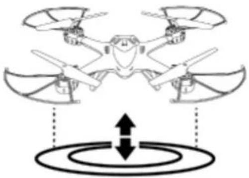
Once signal connection between the drone and the remote is finished, push up the throttle control stick to take off the drone. When the drone is flying more than 1 meter height, release the throttle stick. The drone will keep hovering at the current height.
natural_image
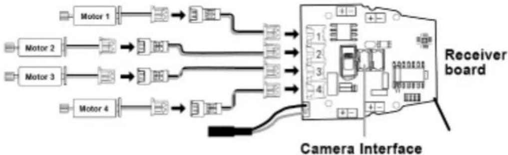
Diagram of a drone with four wings and two control panels, showing concentric circular patterns below (no text or symbols)Schematic diagram of the connection of the motors and the PCB
It is important that the installation of the PCB and the wire connection of the motor to the PCB should be connected properly according to the diagram shown as below.
flowchart
graph LR
    Motor1 --> ReceiverBoard
    Motor2 --> ReceiverBoard
    Motor3 --> ReceiverBoard
    Motor4 --> ReceiverBoard
    ReceiverBoard --> CameraInterface
    CameraInterface -->|Control| Motor1
    CameraInterface -->|Control| Motor2
    CameraInterface -->|Control| Motor3
    CameraInterface -->|Control| Motor4
    style ReceiverBoard fill:#f9f,stroke:#333
    style CameraInterface fill:#ccf,stroke:#333
- Motor 1 should be connected with interface 1.
2.Motor 2 should be connected with interface 2.
3.Motor 3 should be connected with interface 3.
4.Motor 4 should be connected with interface 4.
How to change the motor cabinet
natural_image
Close-up of a hand holding a small electronic component, possibly a sensor or connector (no visible text or symbols)Pic.11
- Take out the screws with a screwdriver by turning counter clockwise.
natural_image
Close-up of a hand holding a small mechanical component, possibly a tool or device (no visible text or symbols)Pic.12
2.Pull out the motor cabinet.
natural_image
Close-up of hands holding a small object with a dark stripe, possibly a tool or component (no visible text or symbols)Pic.13
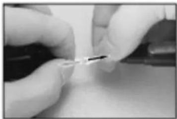
- Unplug the motor wire from the power wire plug.
natural_image
Close-up of hands holding a small object, possibly a tool or device, with no visible text or symbols.Pic.14
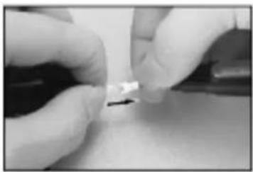
- Connect the motor wire of the new motor cabinet to the power wire plug.
natural_image
Close-up of a gloved hand holding a small mechanical component with an arrow indicating direction (no visible text or symbols)Pic.15
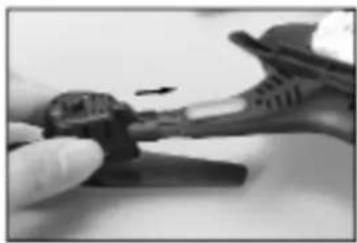
- Install the motor cabinet to the main body of the model.
natural_image
Close-up of a hand holding a tool with a small object inserted, possibly a tool or device (no visible text or symbols)Pic.16
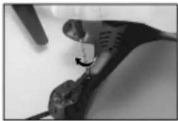
- Lock the motor cabinet with screws.
FPV camera #C4015/#C4016 installation
Installed with #C4015/#C4016 camera, the model can take photos and videos, if download and install the FPV software to the smart phone, FPV real-time transmission can be achieved through the connection of the model and the smart phone.
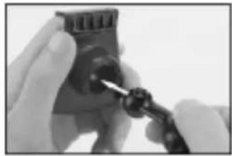
Install the holder of the mobile phone:
natural_image
Close-up of hands using a screwdriver to adjust a small electronic component (no visible text or symbols)Pic.17
- Connect the stand bar to the mobile phone fixing component.
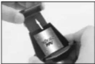
natural_image
Close-up of a hand holding a black mechanical component with a metallic label (no visible text or symbols)Pic.18
- Adjust the fixing component upward or downward according to the size of the mobile phone.
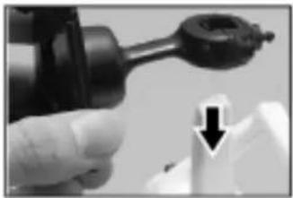
natural_image
Close-up of a hand holding a mechanical component with a downward arrow indicating a process (no visible text or symbols)Pic.19
- Set the mobile phone holder to the top of the remote control.
Remark:
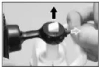
natural_image
Close-up of a hand holding a mechanical component with an arrow indicating upward motion (no visible text or symbols)Pic.20
- Pull back the lock center of the stand bar and slowly push up the holder, the mobilephone holder would be taken down.
#C4015/#C4016 installation:
natural_image
Close-up of a gloved hand using a tool to press or inspect a mechanical component (no visible text or symbols)Pic.21
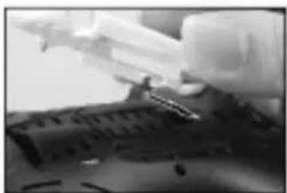
- The camera should be fastened to the interface at the bottom of the model.
natural_image
Close-up of a mechanical component with a metallic tool inserted, showing no visible text or symbols.Pic.22
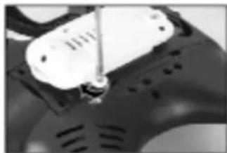
- Fix the camera by screwing clockwise.
natural_image
Close-up of a hand holding a small object with a downward arrow, possibly part of a device or tool (no visible text or symbols)Pic.23
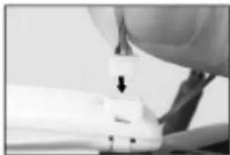
- Insert the camera wire plug to the camera interface.
natural_image
Close-up of a gloved hand inserting a small electronic component into a device (no visible text or symbols)Pic.24
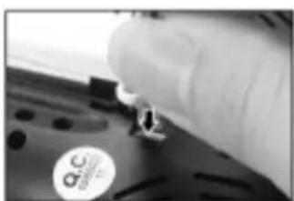
- Insert the camera wire plug to port of camera.
natural_image
Close-up of a mechanical component with a lever and adjustment knob (no visible text or symbols)Pic.25
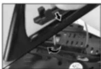
- Insert the antenna bracket into interface of the landing gear and lock the screws.
natural_image
Close-up of a hand holding a black mechanical component with a small arrow pointing to it (no visible text or symbols)Pic.26
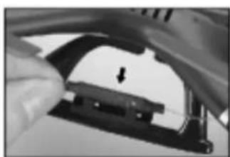
- Install the antenna to the antenna bracket.
FPV real-time transmission software download, installation and function introduction.
Install software
- Mount camera #C4015/#C0416 on the drone and install the "MJX H" software to smart phone, the photos and videos that taking by the camera can be seen alive when the model is flying.
- For Android system, please visit our website www.mjxrc.com to download the software "MJX H".
* For Apple IOS system, please go to the APP store to download the software "MJX H".
There are two modes of the "MJX H"APP
●Real-time images transmission mode

natural_image
Camera icon with lens and button, labeled 'MJX H' (no additional text or symbols)Pic.27
- Open the software "MJX H".
text_image
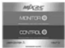
MIXRS MONITOR © CONTROL © LARGE 2018.12.14Pic.28
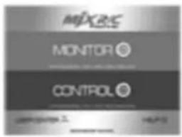
- Click the "MONITOR" button.
natural_image
Black-and-white landscape photo of a rugged mountain range with a winding river below (no visible text or symbols)Pic.29
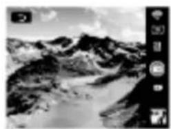
- Real-time image is showing on the screen.
- Mobile phone APP control mode
natural_image
Camera icon with lens and button, labeled 'MJX H' (no additional text or symbols)Pic.30
- Open the software "MJX H".
text_image
MIXRS MONITOR © CONTROL ©Pic.31
- Click the "CONTROL" button.
natural_image
Two identical square buttons with central dots, displayed in a software interface (no text or symbols on buttons)Pic.32
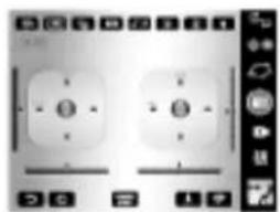
- Activate the mobile phone APP real-time remote control interface.
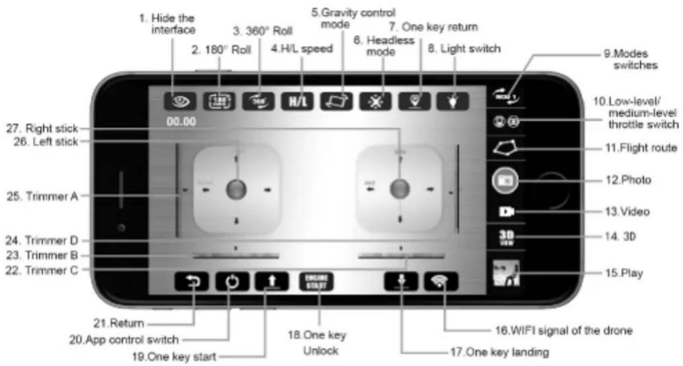
Mobile phone APP "MJX H" control functions introduction
text_image
1. Hide the interface 2. 180° Roll 3. 360° Roll 4.H/L speed 5. Gravity control mode 6. Headless mode 7. One key return 8. Light switch 9.Modes switches 10.Low-level/ medium-level throttle switch 11.Flight route 12.Photo 13.Video 14. 3D 15.Play 16.WIFI signal of the drone 17.One key landing 21.Return 20.App control switch 22.Trimmer C 23.Trimmer B 24.Trimmer D 25.Trimmer A 26.Left stick 27.Right stick 00.00| No. | Function switch | Function description |
| 1 | Hide the interface | Touch this button to hide the menu of the interface. |
| 2 | 180° Roll | Touch this button to rotate the image 180-degree. |
| 3 | 360° Roll | Once the drone is flying in the sky, touch this button the drone will 360 degree roll forward. |
| 4 | H/L speed | Turn on the APP control and then touch this button to enter into high and low speed choosing mode.When the H/L logo is in red color, the drone is in high speed mode; when the H/L logo is in black color, the drone is in low speed mode. |
| 5 | Gravity control mode | Touch this button to enter into the operation interface.MOD 2: The left control stick is the throttle control and left/right turning stick. The right stick is the forward/backward flight and leftward/rightward flight stick.MOD 1: The left control stick is the forward/backward control and left/right turning stick. The right stick is the throttle control and leftward/rightward flight stick.MOD 3: The left control stick is the forward/backward control and leftward/rightward flight stick. The right stick is the throttle control and leftward/rightward flight stick.MOD 4: The left control stick is the throttle control and leftward/rightward flight stick. The right stick is the forward/backward flight and left/right turning stick. |
| 6 | Headless mode | Turn on the remote control. Touch this icon to enter into headless mode and adjust the drone. |
| 7 | One key return | Touch this icon while the drone is in headless mode. The drone will return with rear heading back. |
| 8 | Light switch | Touch this button to turn on or turn off the light. |
| 9 | Modes switches | The 4 modes are as below:MOD 2: The left control stick is the throttle control and left/right turning stick. The right stick is the forward/backward flight and leftward/rightward flight stick.MOD 1: The left control stick is the forward/backward control and left/right turning stick. The right stick is the throttle control and leftward/rightward flight stick.MOD 3: The left control stick is the forward/backward control and leftward/rightward flight stick. The right stick is the throttle control and leftward/rightward flight stick.MOD 4: The left control stick is the throttle control and leftward/rightward flight stick. The right stick is the forward/backward flight and left/right turning stick. |
| 10 | Low-level/medium -level throttle switch | Low-level throttle is for drones without altitude hold mode playing.Medium-level throttle is for drones with altitude hold mode playing. |
| 11 | Flight route | Turn on the APP control, and then tough here to enter into flight plan. The left stick is the throttle control stick; the right control stick is the left and right turning control stick. Touch the stick to control the flight.The blank space of the screen is for flight route drawing.Once the route is draw out,the drone will fly forward,backward, leftward and rightward according to the indication of the route. 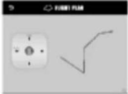 |
| 12 | Photo | Touch here, the camera will take photo. |
| 13 | Video | Touch here, the camera will take video. |
| 14 | 3D | Touch here and wear the 3D VR glasses to experience the 3D effects. |
| 15 | Play | Touch here to play the saved video. |
| 16 | WIFI signal of the drone | It indicates the strength of the WIFI signal. |
| 17 | One key landing | While the drone is flying, touch here to gently land the drone. |
| 18 | One key unlock | Short press this button to unlock the drone when the drone is not unlocked. |
| 19 | One key start | Once the model is unlocked and rotates slowly on the ground. Short press this button, the model will take off automatically. |
| 20 | App control switch | Touch this button, the icon will be in red color while the mobile phone is sending out connection signal.Once the drone's WIFI signal is successfully connected, the drone indicate will be constant "on". |
| 21 | Return | Touch here to exit the APP control interface and enter into mode choosing. |
| 22 | Trimmer C | In stick Mode 3 and 4, it helps to tune the model's left and right direction turning speed.In stick Mode 1 and 2, it helps to tune the model's sideward flight. |
| 23 | Trimmer B | In stick Mode 3 and 4, it helps to tune the model's sideward flight.In stick Mode 1 and 2, it helps to tune the model's left and right direction turning speed. |
| 24 | Trimmer D | In stick Mode 1 and 3, this button is null.In stick Mode 2 and 4, it helps to tune the model's forward and backward flight. |
| 25 | Trimmer A | In stick Mode 2 and 4, this button is null.In stick Mode 1 and 3, it helps to tune the model's forward and backward flight. |
| 26 | Left stick | STICK MODE 2: upward/downward, turn left/turn right;STICK MODE 4: upward/downward,leftward/rightward.STICK MODE 1: forward/backward, turn left/turn right;STICK MODE 3: forward/backward,leftward/rightward. |
| 27 | Right stick | STICK MODE 1: upward/downward,leftward/rightward;STICK MODE 3: upward/downward, turn left/turn right;STICK MODE 2: forward/backward,leftward/rightward;STICK MODE 4: forward/backward, turn left/turn right. |
Instructions on how to take off the drone by mobile phone APP control
Check and make sure that the camera #C4015/#C4016 is correctly mounted on the drone; and then connect the battery wire with the power plug of the receiver PCB. Turn on the drone, the LED light of the drone will flash quickly and the drone is in the gyro detection state. Set the drone to the flat position; enter into settings of the mobile phone. Open WIFI; then, search the WIFI signal "MJX H****" from the WIFI signal list and connect the signal.Exit setting once the mobile phone is connected with "MJX H ****".Open the APP "MJX H" at the mobile phone; click "MONITOR" to enter into real-time images transmission interface to shoot.Click "CONTROL" to enter into the APP control interface. Touch the APP control icon. The icon will be in red color while the mobile phone WIFI is sending out connectional signal. Once the mobile phone's WIFI signal is successfully connected with the drone's WIFI signal, the drone indicator light will be in constant "on".Touch the one key start icon, the drone will rotate in low speed. At this time, push up the throttle control stick icon, the drone will take off.
Turn on and turn off the APP control
Start switch
Landing switch
How to stop the APP mobile phone control in emergency case and how to correct the gyro
Short-press the one key landing button or push the throttle control stick to make the drone gently land to the ground. About 2 seconds later, the drone will thoroughly stop flying.
When the drone is flying less than 1 meter height from the ground, but you need to stop the drone urgently, please turn the left control stick of the remote control to the left-bottom and right control stick to the right-bottom to cease the flying drone.
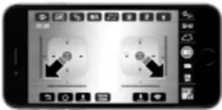
text_image
Mobile phone screenshot showing two identical face detection icons with arrows pointing to them, likely for app or recording purposes.Correction of the gyro
When the model is in headless mode, flight direction proof is needed. Set the head of the model ahead of the player, turn both of two control sticks to the lower right corner for about 2 seconds, the model's indicator light will turn from slowly flashing to quick flashing and flight direction proof is finished.
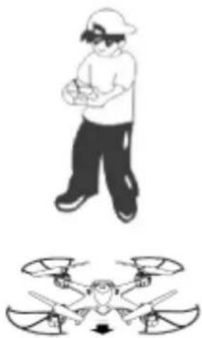
natural_image
Illustration of a person in motion with a drone above it (no text or symbols)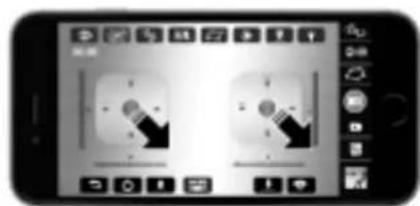
text_image
Smartphone screen displaying a photo editing interface with two identical lock icons and control buttonsAccessories (Optional)
natural_image
Top-down view of a metallic star-shaped object with symmetrical arms and central opening (no text or symbols)401H01 Upper Cover (Golden)
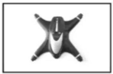
natural_image
Top-down view of a black and white abstract object resembling a stylized star or emblem (no text or symbols)400002 Upper Cover (Black)

natural_image
Top-down view of a metallic mechanical component with four symmetrical arms (no text or symbols visible)401H02 Lower Cover (Golden)
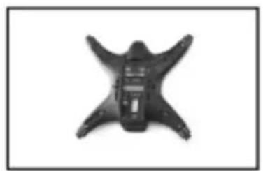
natural_image
Top-down view of a black star-shaped mechanical component with multiple arms and central slots (no text or symbols visible)401H03 Lower Cover (Black)
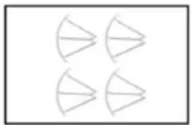
natural_image
Four identical geometric diagrams of a sector with two triangular faces, no text or symbols present.401H04 Protecting Guard (Golden)

natural_image
Symmetrical abstract diagram with four petal-like shapes arranged in a cross pattern (no text or symbols)400006 Protecting Guard (Black)
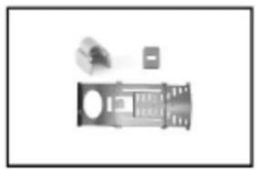
natural_image
Illustration of a stylized building with windows and a small object above it (no text or symbols)401H05 Battery Cover/ Switch Slip Sheet/ Socket (Golden)
natural_image
Black plastic electronic component with three small components, no visible text or symbols400008 Battery Cover/ Switch Slip Sheet/ Socket (Black)
natural_image
Four black mechanical components arranged vertically (no text or symbols visible)400010 Propeller A/B (Black)
natural_image
Four vertical oval shapes arranged in a 2x2 grid on a white background (no text or symbols)400011 Transparent Plastic Part (Blue)
natural_image
Four identical gray oval shapes arranged in a 2x2 grid on white background (no text or symbols)400012 Transparent Plastic Part (Orange)
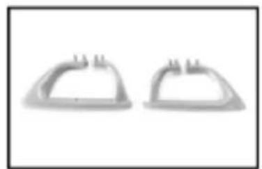
natural_image
Two identical gray plastic dome-shaped objects with protrusions, shown side by side (no text or symbols)401H06 Left/Right Landing Gear (Golden)
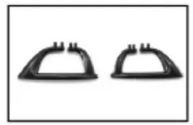
natural_image
Two identical black plastic dome-shaped objects with protrusions, shown side by side (no text or symbols)400014
Left/Right
Landing Gear
(Black)
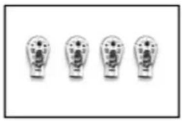
natural_image
Four identical lightbulb-shaped objects arranged horizontally (no text or symbols visible)401H07
Motor Case (Golden)
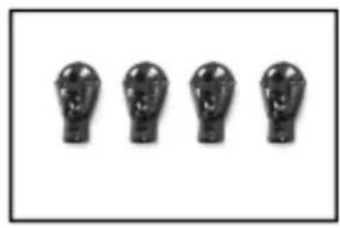
natural_image
Four identical black sculpted human head profiles arranged horizontally on a white background (no text or symbols)400016
Motor Case
(Black)

natural_image
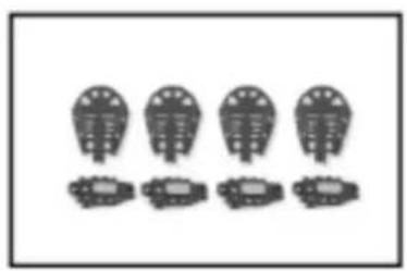
Four identical mechanical components arranged in two rows, no text or symbols visible401H08
Motor Case Cover / Motor Cover (Golden)
natural_image
Four identical bird silhouettes arranged in two rows, each with a small container below (no text or symbols)400018
Motor Case Cover / Motor Cover (Black)
natural_image
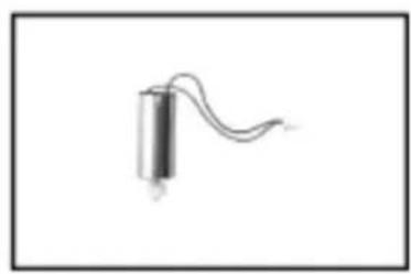
Simple line drawing of a cylindrical object with a curved line extending from it, no text or symbols present.401H09
Clockwise Motor/Motor Gear
natural_image
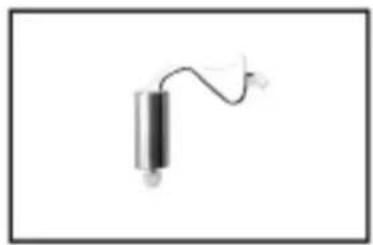
Simple line drawing of a vertical object with a curved line extending from its top, resembling a stylus or abstract shape (no text or symbols)401H10
Counter Clockwise
Motor/ Gear
natural_image
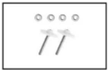
Simple diagram with three circles above two diagonal lines, no text or symbols present300C15
Gear/Copper Bush/Steel Tube
natural_image
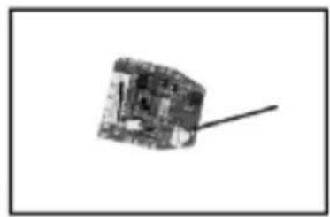
Simple 3D cube-shaped object with a diagonal line extending from its top face, no text or symbols visible.401H11
Receiver PCB
natural_image
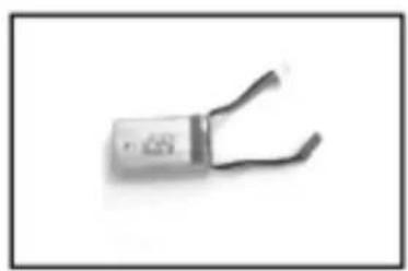
Close-up of a metallic electronic component with two leads (no visible text or symbols)401H12
Battery
natural_image
Abstract black ink blot on white background, no text or symbols visible401H13
USB Charging Cable
natural_image
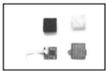
Four small electronic components or modules arranged on a plain background (no visible text or symbols)401H14
Altitude Hold
PCB Component
natural_image
Two abstract curved lines with no text or symbols, resembling stylized strokes or lines (no readable labels or symbols)400022
Front and
rear lights
natural_image
Four identical gray nail screw tips arranged horizontally on a white background (no text or symbols)401H15
Screws Pack
text_image
Scanned document page with Chinese text and a logo, likely an official or corporate announcement.401H50
Manual
text_image
X-GENS 2000 P-05 国产激光雷达系统401H51
Gift Box
natural_image
Two rectangular objects with circular holes, possibly electronic components or devices, shown in grayscale (no text or symbols visible)401H52
Inner blister
natural_image
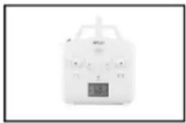
White electronic device with control panel and display screen (no visible text or symbols)GR302
Remote Controller
Trouble shooting
| phenomenon | reason | solution | |
| 1 | The lights are flashing quickly. | Gyro of the model is under signal detecting condition. | Set the model to any flat surface. |
| 2 | The lights are flashing on twice and flashing off once. | The model is not received the signal from the remote control or signal connection is interrupted. | For absence of signal, activate the remote control for the signal connection. For signal interruption, turn off the remote control and turn it on again. |
| 3 | The lights are flashing on and off. | The model is underpowered. | Charge the battery or change another full charged battery. |
| 4 | The model is shaking fiercely. | The rotor blade is out of shape. | Change the rotor blades. |