
20135 - Ferngläser BRAUN - Kostenlose Bedienungsanleitung
Finden Sie kostenlos die Bedienungsanleitung des Geräts 20135 BRAUN als PDF.

| Produkttyp | Marine-Fernglas mit beleuchtetem Kompass |
| Vergrößerung | 7× |
| Objektivdurchmesser | 50 mm |
| Sehfeld | 132 m auf 1000 m |
| Austrittspupille | 6,8 mm |
| Augenabstand | 23 mm (lang, für Brillenträger) |
| Dioptrieneinstellung | -5 bis +5 Dioptrien |
| Pupillenabstand | 56–72 mm |
| Auflösung | ≤ 5" |
| Abmessungen (L×B×H) | 200 × 80 × 150 mm |
| Gewicht (Fernglas) | ≤ 0,9 kg |
| Gewicht (komplett) | ≤ 1,2 kg |
| Stromversorgung Kompassbeleuchtung | 2 Batterien (vorinstalliert) |
| Kompass | Integriert, beleuchtet, Gradskala |
| Entfernungsmessung | Mils-Strichplatte und Drehrechner |
| Stativanschluss | Gewinde am Gelenk |
| Lieferumfang | Fernglas, Trageriemen, Okularschutz, Objektivdeckel, Putztuch, Softcase, Anleitung |
| Material | Gummiarmierung, wasserabweisend |
| Reinigung | Optiktuch, keine Fingerabdrücke |
| Lagerung | Trocken, belüftet, Dioptrie auf 0 |
Häufig gestellte Fragen - 20135 BRAUN
Benutzerfragen zu 20135 BRAUN
0 Frage zu diesem Gerät. Beantworten Sie die, die Sie kennen, oder stellen Sie Ihre eigene.
Eine neue Frage zu diesem Gerät stellen
Laden Sie die Anleitung für Ihr Ferngläser kostenlos im PDF-Format! Finden Sie Ihr Handbuch 20135 - BRAUN und nehmen Sie Ihr elektronisches Gerät wieder in die Hand. Auf dieser Seite sind alle Dokumente veröffentlicht, die für die Verwendung Ihres Geräts notwendig sind. 20135 von der Marke BRAUN.
BEDIENUNGSANLEITUNG 20135 BRAUN
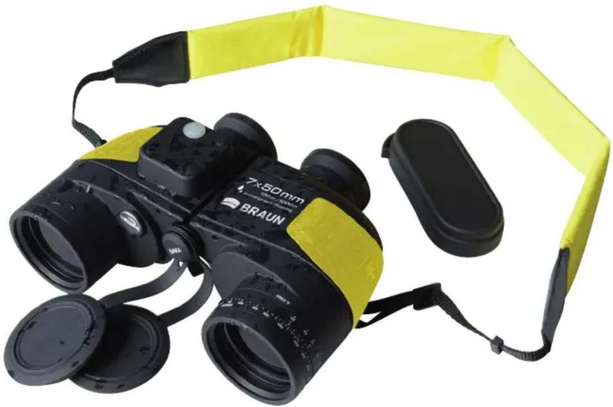
Marine-Fernglas

natural_image
Black and yellow Braun 7x50 mm binoculars with attached strap (no text or symbols visible on the device itself)Gebrauchsanweisung
DE
- General Overview 2
- Technical Specifications 2
- Construction Specifications 2
- How to use the Binoculars 4
- Tripod Mounting 8
- Binoculars and accessories 9
- Storage and Maintenance 9
1. General Overview
1.1 Product Description
These 7x50 binoculars are a floating model with illuminated compass. They have two ranging tools. The eyepiece Mils Reticle Scale and the Calculator Dial can be used to estimate your distance from an object if its size is known, or vice versa. The optics are precision crafted for brightness and clarity of image.
1.2 Model 7×50 with compass
2. Technical Specification
2.1 Optical performance
Magnification: 7×
Field of view at 7x: (132m/1000m)
Exit pupil diameter: 6.8 mm
Exit pupil distance: 23 mm (Long eye relief for eyeglass wearers)
Diopter adjusting range: -5 \~ +5 DIOPTER
Interpupillary distance: 56 \~ 72mm
Resolution: ≤ 5"
2.2 Size and mass
Size (length x width x height): 200 × 80 × 150mm
Weight: Binoculars: ≤0.9kg (1.98 lbs)
Complete product: ≤1.2 kg (2.65 lbs.)
3. Construction Specifications
3.1 Optical system
3.1.1 Basic binocular construction
Basic binocular optical construction, as shown in figure 1, consists of (1) the objective lens, (2) the Porroprisms, (3) the reticle and (4) the eyepiece. Reticle (3) and compass projective systems (5) are built into the right half of the binoculars body.

Fig. 1
3.1.2 How Binoculars work
The light from the object or target you are looking at enters the binoculars through the Objective lens system (item 1, fig. 1). Due to the objective lens, the rays are converged to an upside down image. Then the light rays of the image passes through the prism system (known as the Porroprism) (item 2, fig. 1) and are reversed to erect the image at the reticle (item 3, fig. 1). This image is magnified by the eyepieces (item 4, fig. 1), so that the observer can now see the distant object.
3.1.3 Reticle Scale (See Fig. 3)
There are vertical and horizontal lines on the reticle (3). Each small division on both vertical and horizontal lines represents 5 mils and each numbered division represents 10 mils (one perigon=6400 mils).
So, "1" on the scale is equal to 10 mils.
3.2 Body assembly (Fig. 2)
The binoculars consist of two identical telescopes. Each half consists of the following:
- Eyepiece
- Main binocular body housing the Porroprism assembly
- Objective lens
- Connecting shaft
- Interpupillary scale (56mm-72mm)
- Diopter adjustment ring with index marks (each graduation = 1 diopter)
- Rubber fold-down eyecups
- Calculator dial
- Compass illuminator window
- Compass illuminator On/Off switch
- Battery compartment
- Dust cover for objective lens
- Dust cover for eyepieces

Fig. 2
4. How to use the binoculars
4.1 How to focus the binoculars
4.1.1 Interpupillary adjustment
First adjust the binoculars so that both eyepieces are directly in front of your eyes. This is done by holding the binoculars with both hands and bending the main binocular body housing until you can see one single circular image.
Note: the image will not be clear. You will adjust for clarity in the next step. You must first set the binoculars interpupillary distance to fit your eyes. The setting for your eyes will be indicated on the interpupillary scale (fig.2, 5). Note this scale setting for quicker resetting later.
4.1.2 Rubber fold-down eyecups
These are long eye relief binoculars. They allow the eyeglass wearer to see normal images without removing their glasses. These convenient eyecups fold down for use with glasses and fold up for use without glasses. Lightly press eyecups to fold them down easily.
4.1.3 Focusing
In order to get a clear image, you must focus the binoculars. This model has two individual diopter adjustment rings on each telescope so you can adjust the optics to your individual eyes. You will need to adjust each eyepiece. After placing the binoculars to your eyes and viewing an object, close your left eye. Rotate the right diopter adjustment rings until the object image appears sharp and clear in your right eye. Then open your left eye and close your right eye. Rotate the left diopter adjustment rings until the object image appears sharp and clear in your left eye.
If you share your binoculars with another person, note the diopter index mark setting at the base of the eyepieces first (6). Then you can simply return the eyepieces to those settings when you next use the binoculars to view an object at the same distance.
4.2 How to use the Mils Reticle and Calculator Dial to estimate distance
4.2.1 What is View Angle?
The view angle of an object is the angle from your binoculars to the edges of the object. It is calculated in mils using the Mils Reticle on your binoculars. Using this measurement you can calculate the distance to an object where the height or width of that object is known. This measurement is taken either horizontally or vertically and known as Horizontal View Angle or Vertical View Angle.
4.2.2 How to calculate the Horizontal View Angle of an object
Where the object fits within the horizontal scale range (-40\~+40mils) inside the binoculars, line one edge of the object up with a point on the horizontal scale line and read the value from where the other edge meets the horizontal scale. In fig.4 the right edge of the sail boat is at zero and the left edge at 2 so the horizontal view angle is 20 mils. (1 on the scale = 10mils, 2 = 20mils etc).
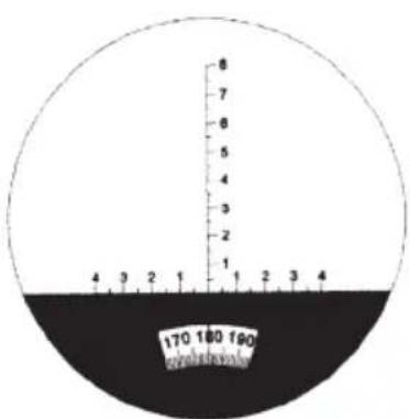
Fig. 3
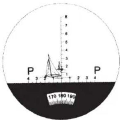
Fig. 4
4.2.2b. How to calculate View Angle when the object is larger than the scale
When the object is larger than the scale, choose a midpoint, take the view angle of this point and multiply by 2.
4.2.3 How to calculate the Vertical View Angle of an object
Use the same method as outlined in 4.2.2 but use the vertical scale.
In fig.5 the base of the light house meets the vertical scale at zero and the top of the lighthouse meets the scale at 6 so the vertical view angle is 60mils.

Fig. 5
4.2.4 How to use your binoculars to estimate distance
(This section shows you how to calculate the distance manually. To use the calculator dial skip to section 4.2.5)
The formula for measuring distance is L(km) = H(m)/w(mils)
Where:
L = the distance between the observer and the object in km
H = the height of the object in m (this must be a known value)
w=the view angle of the object measured using the mils reticle on your binoculars (see fig 4.2.2 and 4.2.3)
When measuring the distance, first estimate the height of the object, then take the view angle reading on your binoculars and enter both into the formula.
For example:
A light house is 12m. (H=12m)
The view angle on the binoculars is 60 mils (see fig.6)
Using the formula L(km)=H(m)/w(mils) we can estimate the distance.
$$ L = 1 2 / 6 0 = 0. 2 \mathrm{km} (2 0 0 \mathrm{m}) $$
Therefore, the distance between the observer and the lighthouse is 200m.

Fig. 6
4.2.5 How to use the calculator on your binoculars to estimate distance
The Calculator Dial can be used to determine the distance quickly and easily without using the above calculation. The Calculator Dial comprises a rotational active ring showing a triangular "ANGLE" marking and a fixed scale marked "DISTANCE". There are two scales in the Active Ring, the upper scale is View Angle and the lower is a Size Scale marked "OBJECT SIZE".
First, measure the View Angle value of an object, rotate the Active Ring and place this value at the Angle Index Mark. Then, find the division indicating the size of the object, where the size meets the distance scale indicates the distance to the object.
For example: See fig 7. You observe a light house and its measured Vertical View Angle is 60 mils. Rotate the Active Ring and place the division marked "6" in the View Scale at the Angle Index Mark. Its height is 12m, the division marked "12" in the Size Scale lines up with the division marked "200" in the Fixed Scale. This tells us that the lighthouse's distance is 200m from us.
Where the size of the observed object is outside the scale just divide the size of the object by a number that will bring your object size to within the scale and divide the View Angle by the same number. As the values are on a fixed scale ratio the resulting value on the dial will be correct. (There is no need to multiply out the result).
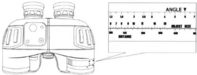
Fig. 7
4.2.6. How to measure an object's size (height and width)
According to the formula for distance measurement, you can calculate the height using: H = L × w . When measuring the size, you first estimate the distance to the object, then measure the View Angle. With these measurements, you can calculate the height of the target using the formula.
For example:
The distance is 0.6km between the observer and the object. The Horizontal View Angle is 60 mils and the Vertical View Angle is 30mils. Using the formula you can get:
The height: H = 0.6 × 30 = 18m
The width: W=0.6 × 60=36m
4.3 How to use the compass
The azimuth angle can be measured through the compass built into the right half of the body. It shows the azimuth of the object relative to the observer. Each graduation of the compass equals one degree. When the object lies to the north, the compass shows 0 (degrees). And it will increase when you turn clockwise. 90^ means the object is located to the east, 180^ means south and 270^ means west.
In order to ensure precise angle measurements, the binoculars should be kept horizontal and level when reading the compass. The object should be in the middle of the reticle.
The graduations of the compass need to be illuminated for easy viewing when there is not sufficient daylight to illuminate the compass dial. (Do not use the battery operated internal illuminating system when the outside viewing conditions are bright enough to see the compass dial and marking clearly.) Pressing the illuminator button will illuminate the compass scale in red.
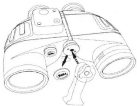
4.4 Changing the batteries
The batteries for the compass will be exhausted if the internal lighting system has been used for long periods. Batteries can also become weak if not used for an extended period of time. If the light becomes dim, open the battery cover and replace with fresh batteries.
Batteries are included and pre-installed in your binoculars. When it becomes necessary to replace them, unscrew the battery cover with a coin or screwdriver and replace with the same type. Be sure to install the batteries in the same direction as the originals, with the flat positive (+) side facing up towards the cover on both batteries. Screw the battery cover back on tightly and press the compass illuminator button to test the light. A glow should be visible around the compass (you may need to cover the right objective lens if you are outside in bright light).
Please note: The two batteries should be replaced at the same time. The batteries should be taken out if the binoculars will not be used for a long time. Batteries left in the binoculars for extended periods of time without being used may leak and cause damage to the binoculars.

Fig. 8
5. Tripod Mounting
A threaded socket for a tripod attachment is located at the base of the binoculars hinge (fig.9) Insert a binoculars tripod adapter, and attach your tripod screw to the base of the adapter.
natural_image
Line drawing of a binoculars with no text or symbolsFig. 9
6. Binoculars and accessories
| 7×50 binoculars | 1 pc |
| Carrying strap | 1 pc |
| Eyepiece cap | 1 pc |
| Lens cleaning cloth | 1 pc |
| Instructions | 1 cop |
| Soft case with carrying strap | 1 pc |
| Objective Lens Cap | 2 pc |
7. Storage and maintenance
Binoculars are a precision optical instrument. They should be carefully handled and maintained in order to keep them in good working order.
7.1 General Maintenance
7.1.1 Lenses: Always clean the lenses after each use and before you replace the binoculars in the carry case. After each use, brush any dust or dirt from the lenses. After brushing, gently wipe each of the lenses with the special optical cloth. Never use your fingers to wipe the lenses as body oil will get on the lenses and possibly damage them. Never use anything to wipe your lenses except special optical cloths. Always keep your optical cloth in the binocular case for easy access for cleaning.
7.1.2 Although the eyepieces are made to turn for individual eye diopter adjustments, do not turn them beyond the factory set stop. Forcing it beyond this point will damage the eyepiece optics and make the binoculars unworkable.
7.1.3 After using, always remember to turn the diopter adjustment to its "0" position to avoid damaging the ocular system.
7.1.4 Avoid any extreme shaking or dropping the binoculars. This may damage the internal optics and prisms. Store the binoculars in a dry and well-ventilated place.
Marine-Binoculars
natural_image
Black and yellow Braun 7x50 mm binoculars with attached strap (no text or symbols visible on the device itself)User's manual
EN
- General Overview 2
- Technical Specifications 2
- Construction Specifications 2
- How to use the Binoculars 4
- Tripod Mounting 8
- Binoculars and accessories 9
- Storage and Maintenance
1. General Overview
1.1 Product Description
These 7x50 binoculars are a floating model with illuminated compass. They have two ranging tools. The eyepiece Mils Reticle Scale and the Calculator Dial can be used to estimate your distance from an object if its size is known, or vice versa. The optics are precision crafted for brightness and clarity of image.
1.2 Model 7×50 with compass
2. Technical Specification
2.1 Optical performance
Magnification: 7×
Field of view at 7x: (132m/1000m)
Exit pupil diameter: 6.8 mm
Exit pupil distance: 23 mm (Long eye relief for eyeglass wearers)
Diopter adjusting range: -5 \~ +5 DIOPTER
Interpupillary distance: 56 \~ 72mm
Resolution: ≤ 5"
2.2 Size and mass
Size (length x width x height): 200 × 80 × 150mm
Weight: Binoculars: ≤0.9kg (1.98 lbs)
Complete product: ≤1.2 kg (2.65 lbs.)
3. Construction Specifications
3.1 Optical system
3.1.1 Basic binocular construction
Basic binocular optical construction, as shown in figure 1, consists of (1) the objective lens, (2) the Porroprisms, (3) the reticle and (4) the eyepiece. Reticle (3) and compass projective systems (5) are built into the right half of the binoculars body.
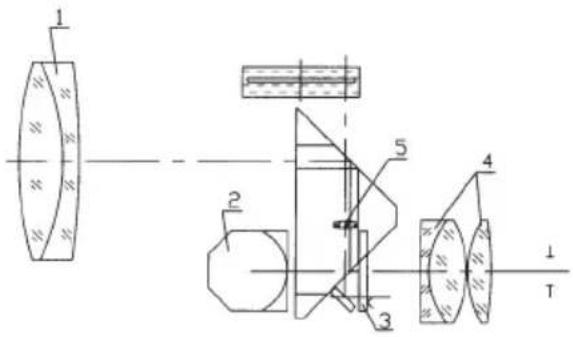
Fig. 1
3.1.2 How Binoculars work
The light from the object or target you are looking at enters the binoculars through the Objective lens system (item 1, fig. 1). Due to the objective lens, the rays are converged to an upside down image. Then the light rays of the image passes through the prism system (known as the Porroprism) (item 2, fig. 1) and are reversed to erect the image at the reticle (item 3, fig. 1). This image is magnified by the eyepieces (item 4, fig. 1), so that the observer can now see the distant object.
3.1.3 Reticle Scale (See Fig. 3)
There are vertical and horizontal lines on the reticle (3). Each small division on both vertical and horizontal lines represents 5 mils and each numbered division represents 10 mils (one perigon=6400 mils).
So, "1" on the scale is equal to 10 mils.
3.2 Body assembly (Fig. 2)
The binoculars consist of two identical telescopes. Each half consists of the following:
- Eyepiece
- Main binocular body housing the Porroprism assembly
- Objective lens
- Connecting shaft
- Interpupillary scale (56mm-72mm)
- Diopter adjustment ring with index marks (each graduation = 1 diopter)
- Rubber fold-down eyecups
- Calculator dial
- Compass illuminator window
- Compass illuminator On/Off switch
- Battery compartment
- Dust cover for objective lens
- Dust cover for eyepieces
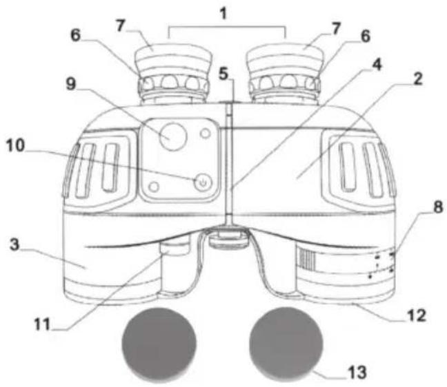
Fig. 2
4. How to use the binoculars
4.1 How to focus the binoculars
4.1.1 Interpupillary adjustment
First adjust the binoculars so that both eyepieces are directly in front of your eyes. This is done by holding the binoculars with both hands and bending the main binocular body housing until you can see one single circular image.
Note: the image will not be clear. You will adjust for clarity in the next step. You must first set the binoculars interpupillary distance to fit your eyes. The setting for your eyes will be indicated on the interpupillary scale (fig.2, 5). Note this scale setting for quicker resetting later.
4.1.2 Rubber fold-down eyecups
These are long eye relief binoculars. They allow the eyeglass wearer to see normal images without removing their glasses. These convenient eyecups fold down for use with glasses and fold up for use without glasses. Lightly press eyecups to fold them down easily.
4.1.3 Focusing
In order to get a clear image, you must focus the binoculars. This model has two individual diopter adjustment rings on each telescope so you can adjust the optics to your individual eyes. You will need to adjust each eyepiece. After placing the binoculars to your eyes and viewing an object, close your left eye. Rotate the right diopter adjustment rings until the object image appears sharp and clear in your right eye. Then open your left eye and close your right eye. Rotate the left diopter adjustment rings until the object image appears sharp and clear in your left eye.
If you share your binoculars with another person, note the diopter index mark setting at the base of the eyepieces first (6). Then you can simply return the eyepieces to those settings when you next use the binoculars to view an object at the same distance.
4.2 How to use the Mils Reticle and Calculator Dial to estimate distance
4.2.1 What is View Angle?
The view angle of an object is the angle from your binoculars to the edges of the object. It is calculated in mils using the Mils Reticle on your binoculars. Using this measurement you can calculate the distance to an object where the height or width of that object is known. This measurement is taken either horizontally or vertically and known as Horizontal View Angle or Vertical View Angle.
4.2.2 How to calculate the Horizontal View Angle of an object
Where the object fits within the horizontal scale range (-40\~+40mils) inside the binoculars, line one edge of the object up with a point on the horizontal scale line and read the value from where the other edge meets the horizontal scale. In fig.4 the right edge of the sail boat is at zero and the left edge at 2 so the horizontal view angle is 20 mils. (1 on the scale = 10mils, 2 = 20mils etc).

Fig. 3
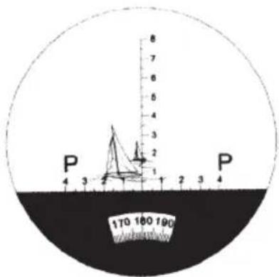
Fig. 4
4.2.2b. How to calculate View Angle when the object is larger than the scale
When the object is larger than the scale, choose a midpoint, take the view angle of this point and multiply by 2.
4.2.3 How to calculate the Vertical View Angle of an object
Use the same method as outlined in 4.2.2 but use the vertical scale.
In fig.5 the base of the light house meets the vertical scale at zero and the top of the lighthouse meets the scale at 6 so the vertical view angle is 60mils.

Fig. 5
4.2.4 How to use your binoculars to estimate distance
(This section shows you how to calculate the distance manually. To use the calculator dial skip to section 4.2.5)
The formula for measuring distance is L(km) = H(m)/w(mils)
Where:
L = the distance between the observer and the object in km
H = the height of the object in m (this must be a known value)
w=the view angle of the object measured using the mils reticle on your binoculars (see fig 4.2.2 and 4.2.3)
When measuring the distance, first estimate the height of the object, then take the view angle reading on your binoculars and enter both into the formula.
For example:
A light house is 12m. (H=12m)
The view angle on the binoculars is 60 mils (see fig.6)
Using the formula L(km)=H(m)/w(mils) we can estimate the distance.
$$ L = 1 2 / 6 0 = 0. 2 \mathrm{km} (2 0 0 \mathrm{m}) $$
Therefore, the distance between the observer and the lighthouse is 200m.
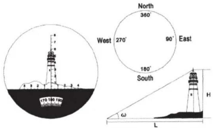
Fig. 6
4.2.5 How to use the calculator on your binoculars to estimate distance
The Calculator Dial can be used to determine the distance quickly and easily without using the above calculation. The Calculator Dial comprises a rotational active ring showing a triangular "ANGLE" marking and a fixed scale marked "DISTANCE". There are two scales in the Active Ring, the upper scale is View Angle and the lower is a Size Scale marked "OBJECT SIZE".
First, measure the View Angle value of an object, rotate the Active Ring and place this value at the Angle Index Mark. Then, find the division indicating the size of the object, where the size meets the distance scale indicates the distance to the object.
For example: See fig 7. You observe a light house and its measured Vertical View Angle is 60 mils. Rotate the Active Ring and place the division marked "6" in the View Scale at the Angle Index Mark. Its height is 12m, the division marked "12" in the Size Scale lines up with the division marked "200" in the Fixed Scale. This tells us that the lighthouse's distance is 200m from us.
Where the size of the observed object is outside the scale just divide the size of the object by a number that will bring your object size to within the scale and divide the View Angle by the same number. As the values are on a fixed scale ratio the resulting value on the dial will be correct. (There is no need to multiply out the result).

Fig. 7
4.2.6. How to measure an object's size (height and width)
According to the formula for distance measurement, you can calculate the height using: H = L × w . When measuring the size, you first estimate the distance to the object, then measure the View Angle. With these measurements, you can calculate the height of the target using the formula.
For example:
The distance is 0.6km between the observer and the object. The Horizontal View Angle is 60 mils and the Vertical View Angle is 30mils. Using the formula you can get:
The height: H = 0.6 × 30 = 18m
The width: W=0.6 × 60=36m
4.3 How to use the compass
The azimuth angle can be measured through the compass built into the right half of the body. It shows the azimuth of the object relative to the observer. Each graduation of the compass equals one degree. When the object lies to the north, the compass shows 0 (degrees). And it will increase when you turn clockwise. 90^ means the object is located to the east, 180^ means south and 270^ means west.
In order to ensure precise angle measurements, the binoculars should be kept horizontal and level when reading the compass. The object should be in the middle of the reticle.
The graduations of the compass need to be illuminated for easy viewing when there is not sufficient daylight to illuminate the compass dial. (Do not use the battery operated internal illuminating system when the outside viewing conditions are bright enough to see the compass dial and marking clearly.) Pressing the illuminator button will illuminate the compass scale in red.
4.4 Changing the batteries
The batteries for the compass will be exhausted if the internal lighting system has been used for long periods. Batteries can also become weak if not used for an extended period of time. If the light becomes dim, open the battery cover and replace with fresh batteries.
Batteries are included and pre-installed in your binoculars. When it becomes necessary to replace them, unscrew the battery cover with a coin or screwdriver and replace with the same type. Be sure to install the batteries in the same direction as the originals, with the flat positive (+) side facing up towards the cover on both batteries. Screw the battery cover back on tightly and press the compass illuminator button to test the light. A glow should be visible around the compass (you may need to cover the right objective lens if you are outside in bright light).
Please note: The two batteries should be replaced at the same time. The batteries should be taken out if the binoculars will not be used for a long time. Batteries left in the binoculars for extended periods of time without being used may leak and cause damage to the binoculars.
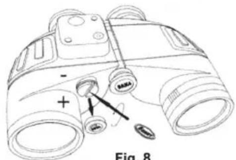
Fig. 8
5. Tripod Mounting
A threaded socket for a tripod attachment is located at the base of the binoculars hinge (fig.9) Insert a binoculars tripod adapter, and attach your tripod screw to the base of the adapter.

natural_image
Line drawing of a binoculars with no text or symbolsFig. 9
6. Binoculars and accessories
| 7×50 binoculars | 1 pc |
| Carrying strap | 1 pc |
| Eyepiece cap | 1 pc |
| Lens cleaning cloth | 1 pc |
| Instructions | 1 cop |
| Soft case with carrying strap | 1 pc |
| Objective Lens Cap | 2 pc |
7. Storage and maintenance
Binoculars are a precision optical instrument. They should be carefully handled and maintained in order to keep them in good working order.
7.1 General Maintenance
7.1.1 Lenses: Always clean the lenses after each use and before you replace the binoculars in the carry case. After each use, brush any dust or dirt from the lenses. After brushing, gently wipe each of the lenses with the special optical cloth. Never use your fingers to wipe the lenses as body oil will get on the lenses and possibly damage them. Never use anything to wipe your lenses except special optical cloths. Always keep your optical cloth in the binocular case for easy access for cleaning.
7.1.2 Although the eyepieces are made to turn for individual eye diopter adjustments, do not turn them beyond the factory set stop. Forcing it beyond this point will damage the eyepiece optics and make the binoculars unworkable.
7.1.3 After using, always remember to turn the diopter adjustment to its "0" position to avoid damaging the ocular system.
7.1.4 Avoid any extreme shaking or dropping the binoculars. This may damage the internal optics and prisms. Store the binoculars in a dry and well-ventilated place.