Challenger SE 490L (1993) - Wohnwagen Swift - Kostenlose Bedienungsanleitung
Finden Sie kostenlos die Bedienungsanleitung des Geräts Challenger SE 490L (1993) Swift als PDF.


Benutzerfragen zu Challenger SE 490L (1993) Swift
0 Frage zu diesem Gerät. Beantworten Sie die, die Sie kennen, oder stellen Sie Ihre eigene.
Eine neue Frage zu diesem Gerät stellen
Laden Sie die Anleitung für Ihr Wohnwagen kostenlos im PDF-Format! Finden Sie Ihr Handbuch Challenger SE 490L (1993) - Swift und nehmen Sie Ihr elektronisches Gerät wieder in die Hand. Auf dieser Seite sind alle Dokumente veröffentlicht, die für die Verwendung Ihres Geräts notwendig sind. Challenger SE 490L (1993) von der Marke Swift.
BEDIENUNGSANLEITUNG Challenger SE 490L (1993) Swift
SWIFT CARAVANS
1 9 9 3
OWNERS HANDBOOK
Introduction
INTRODUCTION
DEAR OWNER,
THANK YOU FOR BUYING A SWIFT CARAVAN. WE ARE SURE YOU WILL ENJOY MANY HAPPY HOURS IN IT AND WE HOPE THE INFORMATION AND HINTS IN THIS HANDBOOK WILL HEIGHTEN YOUR ENJOYMENT.
THE HANDBOOK HAS BEEN DESIGNED TO GIVE YOU A GENERAL GUIDE TO THE CARE, USE AND MAINTENANCE OF YOUR SWIFT CARAVAN. WHETHER YOU ARE A NEW OR AN EXPERIENCED CARAVANNER THE HINTS WILL HELP TO PROTECT YOUR INVESTMENT.
THE INFORMATION CONTAINED WILL ANSWER MOST OF YOUR QUERIES, BUT IF THERE ARE ANY ASPECTS WHICH ARE NOT COVERED PLEASE CONSULT YOUR SWIFT APPOINTED DEALER.
HAPPY CARAVANNING!
Caravan Details

natural_image
Grayscale abstract texture with no discernible text, symbols, or structured elementsIMPORTANT Enter all your caravan details on this page (see specification in rear of this handbook).
| MODEL | Internal length | |||
| MODEL YEAR | Overall length | |||
| CHASSIS NUMBER | Overall width | |||
| KEY NUMBERS | DOOR | Maximum external height | ||
| TOILET | Average unladen weight | |||
| GAS LOCKER | Maximum loading | |||
| BATTERY LOCKER | Maximum laden weight | |||
| BOOT LOCKER | Awning size | |||
| WATER INLET | Tyre pressures | |||
| Supplied and pre-delivery inspection by:- | SERVICE HISTORY | |||
| SIGNED/DEALER | ||||
| DATE | ||||

text_image
CONTENTSServicing 1
The Towing Code 5
Safety and Security 9
Services 23
Electrical Equipment 31
Fitted Equipment 39
Maintenance 61
General Data 71

text_image
SERVICINGAnnual Service Record 2
Servicing
1. 2017年,公司与上海浦东发展银行股份有限公司签订了《关于使用部分闲置募集资金进行现金管理的协议》。
TOURING CARAVANS - ANNUAL SERVICE RECORD
Your caravan needs servicing at least once a year. You have invested in your future holidays and servicing your caravan will help to protect your investment.
Whether you use your caravan for short journeys or for touring at home or abroad, regular servicing will help to ensure that you can enjoy it to the full.
The Annual Service offered by your Swift Dealer will include the following work and we recommend you have your caravan serviced to this standard annually.
The Swift Dealer will complete the record in this handbook to show the work has been carried out.
- Check and test gas system and appliances.
- Check and test electrical system and appliances.
- Check hitch head and over-run device, lubricate as necessary.
- Check and lubricate corner steadies.
- Check brake rods and Bowden cables; adjust brakes.
- Check wheel bearings, grease as necessary.
- Check and ensure that all seals are watertight.
- Carry out damp meter test.

text_image
Service RecordANNUAL SERVICE RECORD
CARAVAN MODEL ____ YEAR ____
CHASSIS NUMBER ____
| 1st SERVICE | 2nd SERVICE |
| DATE: | DATE: |
| DEALER'S STAMP | DEALER'S STAMP |
| We certify that an annual service has been carried out in accordance with the Swift Handbook. | We certify that an annual service has been carried out in accordance with the Swift Handbook. |
| 3rd SERVICE | 4th SERVICE |
| DATE: | DATE: |
| DEALER'S STAMP | DEALER'S STAMP |
| We certify that an annual service has been carried out in accordance with the Swift Handbook. | We certify that an annual service has been carried out in accordance with the Swift Handbook. |
| 5th SERVICE | 6th SERVICE |
| DATE: | DATE: |
| DEALER'S STAMP | DEALER'S STAMP |
| We certify that an annual service has been carried out in accordance with the Swift Handbook. | We certify that an annual service has been carried out in accordance with the Swift Handbook. |
| 7th SERVICE | 8th SERVICE |
| DATE: | DATE: |
| DEALER'S STAMP | DEALER'S STAMP |
| We certify that an annual service has been carried out in accordance with the Swift Handbook. | We certify that an annual service has been carried out in accordance with the Swift Handbook. |
| 9th SERVICE | 10th SERVICE |
| DATE: | DATE: |
| DEALER'S STAMP | DEALER'S STAMP |
| We certify that an annual service has been carried out in accordance with the Swift Handbook. | We certify that an annual service has been carried out in accordance with the Swift Handbook. |

text_image
THE TOWING CODEThe Caravan Towing Code 6
Scope of the Code 6
Caravan Terms 6
Weights 6
Towing Vehicle Terms 6
Weights 6
Measurement of Noseweight 7
Glossary & Checklist 8
Preparing for the Road 10
Checklist 10
Loading & Distribution 10
Stability 11
Pre-tow Checklist 13
Speed Limits 16
Pulling Off 16
Reversing 16
Caravan Handling 16
Motorway Driving 16
Changing a Wheel 17
Jacking Points 17
Stopping on a Hill 17
Arrival on Site 18
The Towing Code
THE CARAVAN TOWING CODE
This Code of Practice contains recommendations jointly reviewed and agreed by the following organizations:
The National Caravan Council The Caravan Club The Camping and Caravanning Club The Caravan Writers Guild The Department of Transport
Scope of the Code
The Code applies to all trailer caravans of maximum laden weight not exceeding 2030 kg (4475 lbs), overall width not exceeding 2.3m (7ft 6in approximately) and overall length not exceeding 7m (23ft approximately), excluding the drawbar and coupling.
CARAVAN TERMS
Ex works weight:
The maximum weight of the caravan as stated by the caravan manufacturer, as new with standard fixtures and fittings.
Note: Because of differences in the weight of materials supplied for the construction of caravans, variation of ±5% of the manufacturer's stated ex-works weight can be expected.
Caravan allowable payload:
The maximum allowable weight of personal possessions, food, equipment and accessories to be put into the caravan whilst it is being towed.
Maximum authorised weight:
The maximum weight for which the caravan is designed for normal use when being towed on a road, laden. This should not be exceeded.
Nose weight:
That part of the weight of the caravan supported by the rear of the towing vehicle.
Notes:
(i) When measuring the noseweight it is important that the caravan is fully loaded. Do not place extra items indiscriminately into the caravan after this adjustment has been made.
(ii) The caravan is intended to be towed slightly nose heavy. The nose weight can be adjusted by distribution of the load within the caravan. The nose weight should be approximately 7% of the actual laden weight. See section on Measurement of Nose Weight.
TOWING VEHICLE TERMS
Kerb weight:
The weight of the towing vehicle as defined by the vehicle manufacturer.
The Caravan and Towing Vehicle Weight Ratio.
This can be determined by calculation and is equal to:
actual laden weight of caravan kerb weight of towing vehicle × 100%
THE LAW REQUIRES THAT CARAVANS & THEIR TOWING VEHICLES & THE LOADS THEY CARRY MUST BE IN SUCH A CONDITION THAT NO DANGER OR NUISANCE IS CAUSED.
(Regulation 100 of the Road and Vehicles [Construction and Use] Regulations 1986).

text_image
Scanned document page with dense Chinese text, likely a formal letter or official record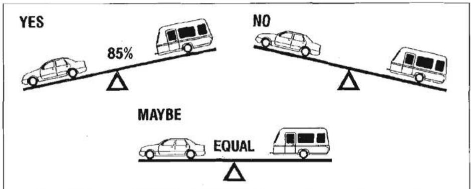
text_image
YES NO MAYBE EQUALFig. A Car/Caravan Weight Ratios
Power to weight ratio:
No hard and fast rules can be stated but, here is a general guide.
(a) Conventional petrol engines with a capacity up to approximately 1500 cc should be adequate for towing a caravan weighing around 85% of the kerb weight of the towing vehicle.
(b) Above 1500 cc such engines should manage a caravan weighing up to 100% of the kerb weight of the towing vehicle and still give adequate performance.
Note: The towing vehicle manufacturer's limit is, in some cases, less than the kerb weight.
Vehicles with automatic transmission may need an oil cooler fitting or the SAE rating of the gearbox oil increasing when towing. The advice of the vehicle manufacturer should be sought.
Actual laden weight
Caravanners can use a public weighbridge to establish the actual laden weight.
Note: Weighbridges have varying weight tolerance levels.

text_image
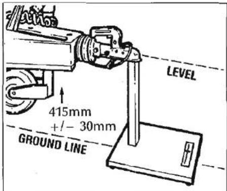
LEVEL 415mm +/- 30mm GROUND LINEFig. B Measuring Noseweight
MEASUREMENT OF NOSEWEIGHT
Noseweight may be measured using a propriety brand of noseweight indicator.
Such equipment is obtainable at your Swift Caravan Dealer.
Another simple method is to use bathroom scales under the coupling head with a piece of wood, fitted between the coupling head and the scales, of such length that the caravan floor is horizontal with the jockey wheel raised. (Fig. B)
Noseweight can be adjusted simply by distribution of weights in the caravan. (See Loading).
The Towing Code
GLOSSARY & CHECKLIST
Awnings - Can consist of just a simple top sheet but may extend to a five sided frame tent attached to the side of the caravan.
Fire blanket - approved to BS 6575 is ideal for dealing with 'fat pan' fires.
Fire extinguisher – It is strongly recommended that a fire extinguisher is carried in the caravan. (For suitable types see Safety and Security).
Gas bottles - Bottled L.P. gas is the most convenient portable source of fuel. Two bottles are required for a constant supply. An initial deposit is payable on each cylinder. (For detailed information see Services - Gas).
Jack - A suitable jack is essential (screw, scissor or air jack type). Many car jacks are unsuitable.
Levellers - Levellers help level the caravan from side to side before unhitching. Proprietary products can be purchased from your caravan dealer and need to be positioned as indicated by the spirit level.
Spare Wheel -It is always advisable to carry a spare wheel for your caravan.
Spirit Level - A spirit level is extremely useful when siting the caravan.
Stabiliser - Stabilisers help to dampen the side to side movement of the caravan.
One end fits to the car's towing bracket and the other end to the caravan. (See Stability)
Torque Wrench - A torque wrench is the only way that the exact recommended torque can be achieved for wheel nuts and bolts. (See Preparing for the Road)
Towing bracket - Car manufacturers recommend that their own bracket is fitted at a specialist dealer, to ensure that it is fixed to the correct mounting points. Never use cheap alternatives, obtain one manufactured by a reputable company.
Wooden blocks - Wooden blocks typically 25cm. square and 2cm. thick are ideal for placing under corner steadies and jockey wheel when the ground is uneven or soft.
Water Containers - Two containers are required, one to carry fresh water to the caravan and one for waste water, which needs to be disposed of properly. Several types are available including jerry cans, folding cans and wheeled containers.
12N & 12S Sockets – Two sockets designated 12N and 12S are fitted to your car to accept corresponding plugs from the caravan. These are necessary to energise the road lights and caravan auxiliary circuits respectively.
12 Volt Battery - A deep cycling, heavy duty leisure type battery should be purchased to provide back-up power for
lights, refrigerator and other electrical appliances. (See Battery).
Useful memory aid for other essential items.
Car
Distilled water
External mirrors
Fan belt
Fire extinguisher
Jack
Jump leads
Petrol can
Socket set
Spare bulbs
Spare keys
Spare wheel
Tool kit
Towball cover
Tow rope
Tyre pressure gauge
Warning triangle
Tyre pump
Caravan
Awning pegs and poles
Awning ground sheet
Battery 12 volt charger
Bucket
Chemical toilet
Corner steady brace
Corner steady pads
Coupling lock
Door mat
The Towing Code
Fire blanket
Fire extinguisher
Fresh water container
Gas cylinder
Gas regulator
Jack
Levelling Boards
Mallet
Site/caravan mains lead
Spare bulbs
(Mandatory in E.C.)
Spare 12v fuses
Spare gas hose
Spare wheel
Spirit level
Toilet fluid
Waste water container
Wheel brace
Personal
After sun cream
First Aid Kit
Flannels
Hairbrush and comb
Make up. etc.
Raincoats
Toothbrush
Toothpaste
Scissors
Shampoo
Shaving kit
Shoe cleaning kit
Soap
Sun tan oil
Wellington boots
Domestic
Adhesive tape
Air freshener
Aluminium foil
Ashtrays
Bin liners
Binoculars
Bottle opener
Breadboard
Breadbin
Brush and dustpan
Butter dish
Camera and films
Carving knife
Cassette recorder
Chairs
Clock
Clothes brush
Clothes line
Coat hangers
Coffee percolator
Coolbox
Colander
Crockery
Cruet
Corkscrew
Cutlery
Dish cloth and brush
Dusters and polish
Disposable cloths
Egg cups
Electrical extension lead
Floor cloth
Fly spray
Food
Food mixer
Frying pan
Glasses
Grill pan
Jugs
Kettle
Kitchen roll
Kitchen tools
Litter bin
Matches
Measuring jug
Milk jug
Mixing bowl
Needles and thread
Oven gloves
Pegs
Piezo Gas lighter
Potato peeler
Pressure cooker
Radio
Rubbish bin
Salad shaker
Saucepans
Scissors
Sieve
Sugar bowl
Shopping bags
Sleeping bags
Tea pot
Tea strainer
Tea towels
Table cloths
Table mats
Television
Tin opener
Tissues
Toilet paper
Torch
Towels
Toys & Games
Vacuum cleaner
Washing up bowl
Documents
Bank and credit cards
Cheque book
Driving licence
Maps and guides
Money
MOT Certificate
The Towing Code

natural_image
Pure horizontal gradient bar with no text, numbers, or symbols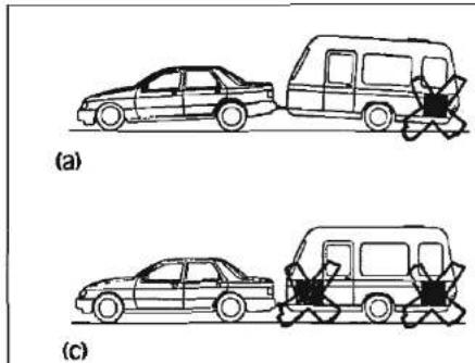
text_image
(a) (c)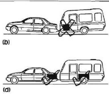
text_image
(b) (d)Fig. A Loading your Caravan
PREPARING FOR THE ROAD
PRE-LOAD CHECKLIST
Caution: Never enter the caravan without first lowering the four corner steadies with the brace provided.
BEFORE LOADING CHECK:
- loose articles are stowed securely. Do not stow tins, bottles or heavy items in overhead lockers prior to towing.
- all lockers and cupboard doors are closed and secured.
- all bunks are secure.
- all rooflights are closed and secured.
-
main table is stored in its transit position.
-
fridge is on 12v operation and door lock is set.
- all windows are fully closed and latched. Never tow with windows on nightsetting. Leave all curtains and blinds open to aid rear visibility.
- gas cylinders are correctly positioned, secured and turned off.
- battery is secure and mains connecting cable is disconnected and stowed.
- 12v distribution panel selector switch is set to centre position.
LOADING AND DISTRIBUTION OF WEIGHT IN THE CARAVAN
Do not exceed recommended maximum loading for your caravan.
- Load heavy items low down near the floor and mainly over or in front of the axle(s). (Fig. A - Page 10)
- Load evenly right to left.
- Do not load items at the extreme front or rear since this can lead to instability due to the 'pendulum effect'.
- Load remainder to give a suitable noseweight at the towing coupling. Check noseweight.
Note: Do not overload car boot.

text_image
The Towing Code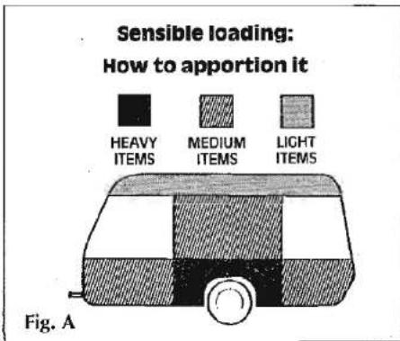
text_image
Sensible loading: How to apportion it HEAVY ITEMS MEDIUM ITEMS LIGHT ITEMS Fig. ATowing vehicle's rear suspension
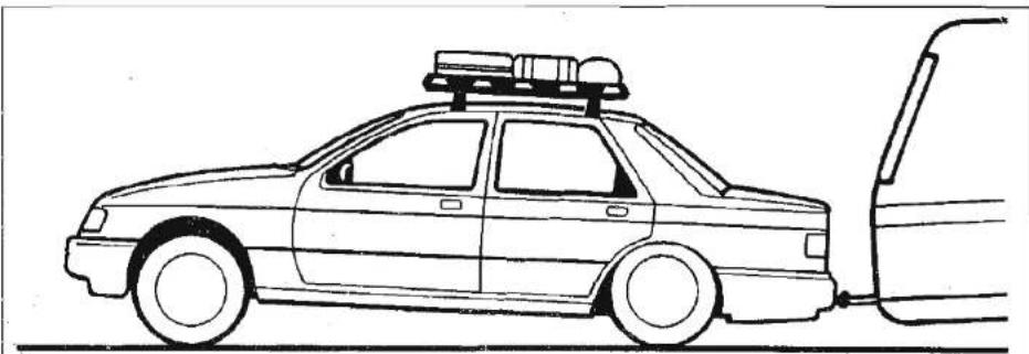
It is important that the towing vehicle's rear suspension is not deflected excessively by the noseweight on the tow ball. If it is excessive the steering and stability will be affected. (Fig. B)
The greater the towing vehicle's tail overhang (the distance between the rear axle and the tow ball) the greater the effect the noseweight will have on the towing vehicle's rear suspension.
After trying out the caravan it may be found that stiffening of the rear suspension is necessary - but note that this may give the towing vehicle a firmer ride when not towing.
natural_image
Side profile line drawing of a car with roof-mounted equipment and exhaust pipe (no text or symbols)Fig. B Illustration of excessive deflection of vehicle's rear suspension
There are a number of suspension aids available and advice should be sought on which to use and how to fit. It is important to ensure that the caravan is towed either level or slightly nose down.
If you have any doubts about the suitability of your towbar for towing a twin axle caravan consult the towing bracket manufacturer.
STABILITY
All models manufactured by Swift are of a well balanced design and should be exceptionally good towers. The most common causes of poor stability include:
(a) Worn springs or loose spring fixings on the towing vehicle.
(b) Towing vehicle springs too soft.
(c) Insufficient noseweight.
(d) Nose of caravan is towing too high.
Towing Aids
Aluminium chassis
If fixing a towing aid to the aluminium chassis you should always ensure that:
(a) the nuts and bolts are either zinc coated or stainless steel and
(b) there is an invert material gasket between the two different metals.
(Failure to do so will result in the metals interacting.)
The Towing Code
(c) maximum three holes in one member or two holes in both members.
It is recommended that stabilizers are fitted by your dealer since the drilling of aluminium drawbars requires certain precautions to be taken.
Galvanised steel chassis
Drilling of the galvanised steel chassis will invalidate the warranty. If fixing a towing aid, in the first instance consult your dealer as regards suitability.
Never drill the coupling head to aid the fitting of a stabilizer.
Suitable towing vehicles
The caravan is manufactured for towing behind normal road cars and is not suitable for towing behind commercial vehicles other than passenger car derivatives. If in doubt please consult Swift Caravans.
Snaking
This is a term used to denote an unstable car and caravan combination where the caravan 'weaves' from side to side often causing a similar swaying movement in the car itself.
Causes:
i) Unsuitable or unbalanced outfit.
ii) Incorrect loading or weight distribution.
iii) Excessive speed especially downhill.
iv) Side winds.
v) Overtaking.
vi) Being overtaken by a large fast moving vehicle.
vii) Erratic driving.
viii) Insufficient tyre pressures.
ix) Mixing radial and cross ply tyres.
Cures:
Cases of persistent snaking can be alleviated by the use of a stabiliser, about which your dealer will advise you.
On the road
If you do find your outfit snaking, try to keep the steering wheel in a central position as far as possible, decelerate and avoid braking if possible.
OTHER IMPORTANT TOWING CONSIDERATIONS THAT COULD AFFECT STABILITY
Types of tyres fitted
The tyres fitted by Swift Caravans are suitable for towing at sustained speeds of up to 81 mph (130 kph).
Radial and cross ply tyres should never be mixed. It is dangerous and can cause snaking.
Periodically tyres should be rotated to equalise wear in the same manner as car tyres.
Do not mix four ply /six ply tyres on the same axle.
Tyre Tread
This caravan is subject to the same criteria applied to car tyres, namely; the minimum tread should be 1.6 mm around the total circumference and across the entire width of the tyre.
Tyre pressures
Caravan and towing vehicles tyres must be at the pressures recommended for towing or heavy loading as stated in handbook not on tyre wall. Towing stability may otherwise be affected. The pressures can be found in the towing vehicle handbook and under the caravan specification in this handbook.
Note: Although the caravan may be fitted with the same type of tyre as the towing vehicle, the pressures specified are different. All charts show values for cars and are therefore not applicable for caravans. Pressures displayed on tyre walls apply ONLY in North America and Canada.
Wheels
Caravan wheel nuts should be tightened to a torque of 9kg/m (65lb/ft) and should be checked with the use of a torque wrench regularly.
The Towing Code
Only use a spare wheel and tyre recommended by Swift Caravans.
Wheel Rims
All caravans manufactured by Swift, since 1988, have been fitted with wheel rims supplied by H.G. Smith Ltd of Willenham. These wheels are the wider 5J size incorporating a double safety hump rim which conforms to European standards of safety. Prior to 1988 a considerable proportion of Swift caravans were fitted with Smith's wheel rims.
If you are in any doubt, have your wheels checked by a competent tyre supplier.
Hitch head load capacity
The maximum vertical static loads which can be put upon the hitch head when connected are:
(a) Single axle caravan - 75kg
(b) Double axle caravan - 100kg
(But see also vehicle manufacturer's weight limits on towball loading.)
PRE-TOW CHECKLIST AND HITCH-UP
Check Gas Locker, Battery Locker (if fitted) and Cassette Toilet (if fitted) door/s are secure.
Check wheelnuts, tyre pressures and tyre conditions.
natural_image
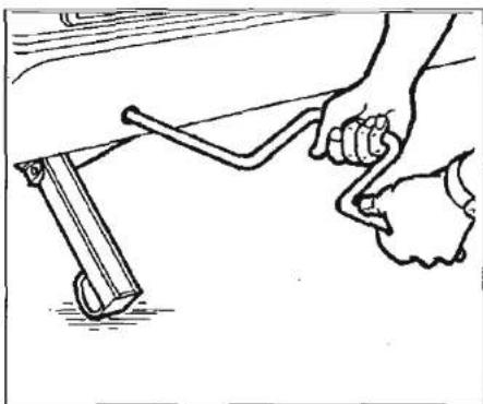
Line drawing of a hand using a tool to lift a wooden plank (no text or symbols)Fig. A Winding Corner Steady
Fully raise all four corner steadies. (Fig. A) Pick up any levelling pads or levelling boards.
Lock the caravan exterior door.
An assistant can help in the hitching operation by standing on the left hand side of the drawbar (facing rear of car) and extending an arm horizontally to indicate position of the coupling. When reversing aim the towball of the car directly at the caravan drawbar. Remove towball cover and keep in car.
Adjust the jockey wheel to ensure the cup is high enough to slide over the towball.
natural_image
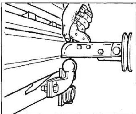
Illustration of a hand using a tool to lift a mechanical component (no text or symbols visible)Fig. B Safety Catch and Handle
Release caravan handbrake.
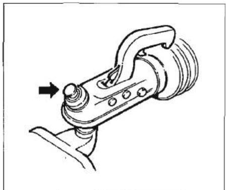
Position cup over greased towball, release safety catch and lift handle (Fig. B). The hitch head is fitted with a visual indicator to show whether or not it is properly connected to the towball. A green band will show immediately below the red indicator button on the hitch head when a proper connection has been made. (See Fig. D, Page 14)
WARNING: If the green band is showing when the hitch head is not connected to the towball there is a fault - contact your Dealer.
The Towing Code
natural_image
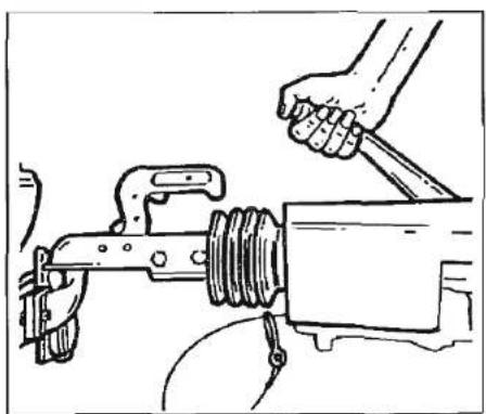
Line drawing of a hand using a tool to lift a mechanical component (no text or symbols)Fig. A Handbrake
Adjust jockey wheel to lower cup on to the ball. A click indicates it is fully engaged. Ensure locking button has returned to its free position.
Secure caravan handbrake. (Fig. A)
Connect breakaway cable (emergency braking device, see inset) to suitable anchorage point on towbar. DO NOT attach to towball.
Ensure that the jockey wheel is fully wound up and properly located in the slots, then undo the clamp handle, lift the whole unit as high as possible and retighten the clamp handle.
Note: Ensure jockey wheel locates in recess provided.
natural_image
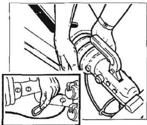
Technical illustration showing hands operating a mechanical device with a close-up inset of the component (no text or symbols present)Fig. B Checking Secure Attachment
Take hold of the caravan under the rubber gaiter behind the coupling and lift to ascertain whether the caravan is properly attached. (Fig. B)
Lock hitch if possible (see Safety and Security page no. 21.).
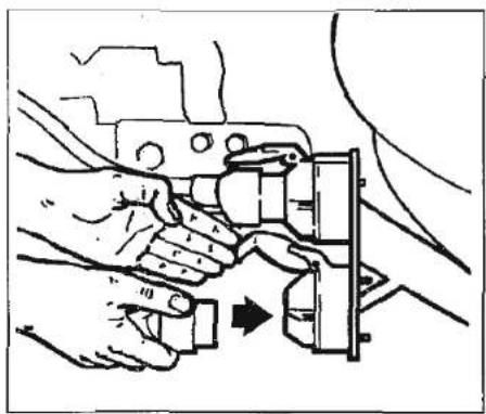
Connect 7 pin plugs to car sockets ensuring there is enough loose cable for cornering. (Fig. C)
Check all car and caravan roadlights are working.
Check round the caravan for anything left behind.
Release caravan handbrake, adjust all mirrors from driving seat and proceed.
natural_image
Illustration of hands using a tool to adjust or install a mechanical component (no text or symbols visible)Fig. C Connections - 7 pin Plug
natural_image
Technical line drawing of a mechanical component with a directional arrow indicating motion (no text or symbols)Fig. D Hitch Head Visual Indicator
natural_image
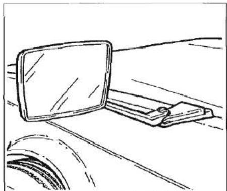
Simple line drawing of a desk with a monitor and a chair (no text or symbols)Fig. A Wing Mirror
Mirrors
The driver of the towing vehicle must have an adequate view of the rear.
If there is no rear view through the caravan it is essential that additional exterior towing mirrors are fitted.
Caution: Any rear view mirror must not project more than 200 mm outside:
a) the width of the caravan when being towed.
b) the width of the towing vehicle when driven solo.
12N and 12S viewed from rear of plug
12N (BLACK)
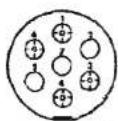
| TERMINAL | COLOUR | 12N PLUG |
| 1 | YELLOW | L/H INDICATOR |
| 2 | BLUE | REAR FOC LAMP |
| 3 | WHITE | COMMONRETURN (EARTH) |
| 4 | GREEN | R/H INDICATOR |
| 5 | BROWN | R/H SIDE TAIL |
| 6 | RED | STOP LAMP |
| 7 | BLACK | L/H SIDE TAIL |
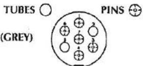
| TERMINAL | COLOUR | 12S PLUG |
| 1 | YELLOW | REVERSING LIGHT |
| 2 | BLUE | BATTERY CHARGING |
| 3 | WHITE | COMMON RETURN (EARTH) |
| 4 | GREEN | INTERIOR LIGHTS |
| 5 | BROWN | NO ALLOCATION |
| 6 . | RED | ERIDGE |
| 7 | BLACK | NO ALLOCATION |
Fig. B Wiring of 12N & 12S Plugs
Note: Any rear view mirror fitted shall be 'e' marked and cover the field of view as stipulated by type approval requirements (Regulation 33 of the Road Vehicles [Construction and Use] Regulation 1986).
Brakes/breakaway cable
A breakaway cable is required for caravans and the device must be such that the caravan stops automatically if the coupling breaks (Regulation 15 of the Road Vehicles [Construction and Use] Regulations 1986).
Always ensure that the breakaway cable is connected to the towing vehicle, not to the towball.
Passengers
Passengers are forbidden to ride in a caravan with the exception of authorized test personnel.
Road lighting
For your information the wiring diagram of the 12N and 12S connectors is shown above (Fig. B). These should be checked regularly and if in any doubt a qualified electrician consulted.
The Towing Code
SPEED LIMITS
Normal road towing: 50mph
Motorways (including dual carriageways): 60mph
PULLING OFF
Let the clutch in smoothly.
Allow more engine speed to produce the power to move the additional weight of the caravan.
Reduce wear and tear on clutch and transmission by taking extra care.
Change gears smoothly.
Try not to jerk the clutch.
REVERSING
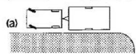
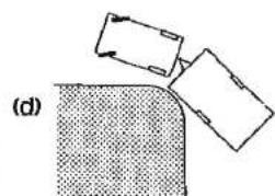
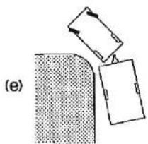
Proficiency at reversing can only be achieved with practice and should be first attempted in a large open area (Fig. A).
natural_image
Diagram showing two rectangular objects interacting with a textured surface, labeled (d), with no visible text or symbols.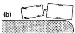
natural_image
Diagram showing a surface with a shaded region and two rectangular objects above it, no text or symbols present.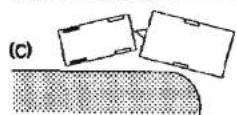
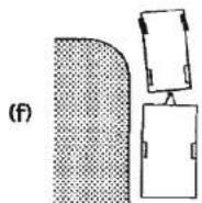
Fig. A Reversing
CARAVAN HANDLING
Allow for caravan being wider than car.
Do not bump kerb with caravan wheels.
When passing other vehicles allow more than the normal clearance for driving solo.
Allow longer to get up speed to pass.
Allow for the outfit being twice its normal length.
Do not suddenly swing out.
Carry out all manoeuvres as smoothly as possible.
Use nearside wing mirror to check caravan has cleared when overtaking.
IMPORTANT POINTS ESPECIALLY FOR MOTORWAY DRIVING
-
Caravans may not be towed in the outside lane of a three or four lane motorway. (Reg. 12(2) of the Motorway Traffic [England and Wales] Regulations 1982).
-
Reduce Speed:
i) In high or cross winds.
ii) Downhill.
iii) In poor visibility.
- High sided vehicles cause air buffeting so extra care must be taken when passing or being passed. As much space as possible should be given.

natural_image
Grayscale abstract texture with horizontal bands and no discernible text or symbols
text_image
Chassis Axle Fig. A jacking Point 50mm 'V' Head Scissor Jack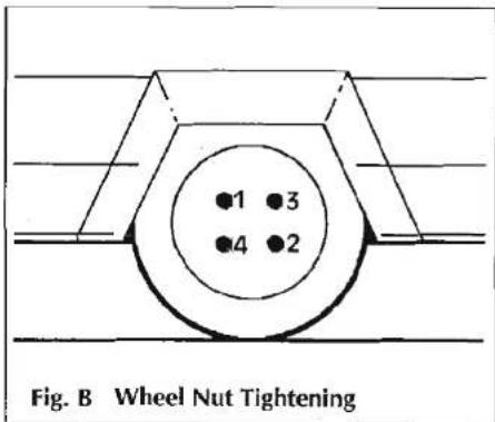
text_image
Fig. B Wheel Nut TighteningCHANGING A WHEEL
- Unhitch the caravan and ensure handbrake is applied.
- Lower corner steadies as safety measure to stabilise the caravan.
- Use wheel brace to slacken off wheel nuts on the wheel to be changed.
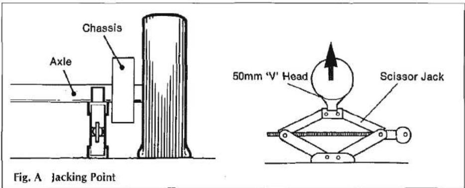
- Position jack under the axle at the appropriate jacking point (see fig. A).
- Jack up the caravan until the wheel for removal is just off the ground.
- Remove the wheel nuts, wheel trims and remove the wheel.
- Fit spare wheel and reverse the above procedure.
- Tighten all four nuts equally according to fig. B.
IMPORTANT
When a wheel has been removed and replaced the torque of the wheel nuts should be checked after approximately 15 miles of running. (See p. 12).
JACKING POINTS
It is recommended that the jack is located in the correct position i.e. on the axle tube inside the chassis member (Fig. A). The reinforced axle mounting plate can be used as an alternative but the chassis-member itself MUST NEVER be used as a jacking point.
STOPPING ON A HILL
Pulling off again can sometimes present a problem. The easy solution is
(i) Carry a good sized wedge shaped piece of wood with a rope or light chain attached.
(ii) Attach the other end of the rope to the nearside rear grab handle.
(iii) Place the wood behind the nearside caravan wheel.
(iv) Carefully reverse the car slightly back down the hill, the caravan will stop against the wedge and turn.
(v) Drive forward since this attempt to move up the hill will now not involve pulling the full weight of the caravan until the car has gained some traction.
The Towing Code
ARRIVAL ON SITE
Note: Check and observe site regulations.
1. Selecting a pitch.
Do not pitch in such a position that your outfit will obstruct others coming in.
Try to choose an area which is dry, reasonably level and preferably with a hard base.
If you have no alternative but to pitch on a slope ensure that, for when you leave, you are facing down the slope.
It is good practice to chock the wheels of the caravan when parked on a slope even though the caravan brakes are applied.
2. Levelling the caravan
Levelling must be carried out in both directions in order for the refrigerator and other equipment to function correctly.
The positioning of the jockey wheel can be used to help level the caravan.
Lower the corner steadies until they are in firm contact with the ground. DO NOT use the steadies as a jack they are only a means of stabilising the caravan.
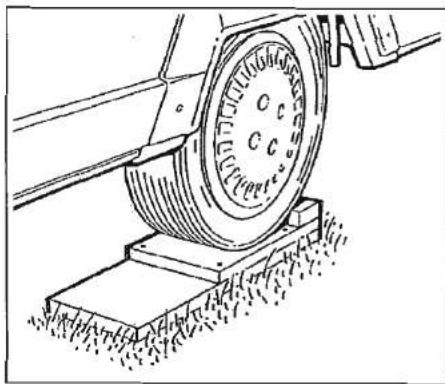
Levelling pads or boards should be used under the steadies where the ground is soft or uneven. Stepped levelling boards can easily be constructed (Fig. A).
In extreme cases where it is necessary to raise a wheel off the ground for levelling purposes, further adequate support should be applied so that the steadies do not take any undue strain.
Exterior Door
To prevent distortion of the body, the caravan must be always correctly sited and levelled. Failure to site the caravan correctly may prevent the exterior door from closing properly.
3. Unhitching
Apply the caravan handbrake.
Unclamp and lower the jockey wheel to the ground.
OR operate the handle and manually lift the coupling head clear of the towing ball.
NOTE: Serious damage will occur unless the locking button is depressed first and the handle lifted forward before the caravan is lifted manually. This prevents the noseweight being transmitted through the locking button.
Re-clamp jockey wheel if necessary.
Disconnect the breakaway cable.
Disconnect the two 7 pin plugs and return them to their holders.
natural_image
Technical line drawing of a mechanical assembly with a wheel and base mount (no text or symbols)Fig. A Levelling Board
Replace towball cover.
Park your vehicle alongside the caravan on the offside.

text_image
SAFETY AND SECURITYFire 20
Notice 20
In Case of Fire 20
Smoke Alarm 20
Fire Extinguishers 21
Children 21
Ventilation 21
Security 21
Theft 21
Chassis Number 21
Additional Security 21
Safety & Security
FIRE
Important: Your attention is drawn to the notice affixed inside the caravan advising on fire precaution, ventilation and what to do in case of fire.
IN CASE OF FIRE
- Get everyone out of the caravan as quickly as possible using whichever exit is the quickest, including windows. Do not stop to collect any personal items.
- Raise the Alarm. Call the Fire Brigade (in the UK dial 999 and ask for the Fire Brigade).
- Turn off the gas supply valve if it is safe to do so.
DICON SMOKE ALARM
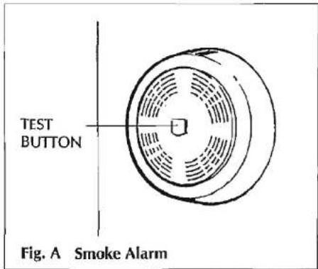
This smoke alarm is approved for use in caravans and mobile homes. (Fig. A)
The National Caravan Council requires that all new or used caravans sold by its members be fitted with a smoke alarm featuring an alarm silence facility.
TO ACTIVATE ALARM-PAUSE
Simply press the test button for a minimum of 5 seconds then release to activate the Alarm-Pause feature. In this mode, the unit should not respond to smoke (by sounding an alarm) for a period of approximately 10 minutes unless the
text_image
TEST BUTTON Fig. A Smoke Alarmlevel of smoke concentration becomes very heavy. During the Alarm-Pause period, the smoke alarm should 'beep' approximately once every 60 seconds to alert the household that the smoke alarm is on Alarm-Pause.
HOW TO TEST
At least once a week, press the test button until the alarm sounds, then release. REMEMBER RELEASING THE TEST BUTTON AUTOMATICALLY ACTIVATES THE ALARMS-PAUSE FEATURE FOR APPROXIMATELY 10 MINUTES.
BATTERY REPLACEMENT
A low battery warning (intermittent
text_image
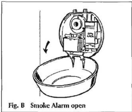
Fig. B Smoke Alarm openbeeping) will indicate the need for battery replacement, for up to 30 days. Refer to the label on the inside of the smoke alarm lid for recommended batteries. The battery should be replaced at least annually.
LIMITATIONS OF SMOKE ALARMS
Smoke alarms cannot work without power. Battery operated alarms will not work without proper batteries, with dead batteries or if batteries are not properly installed. (Fig. B)
Smoke alarms are incapable of sounding the alarm until smoke reaches the sensing chamber. Anything preventing smoke from reaching the detector may delay or prevent an alarm.

natural_image
Grayscale abstract texture with horizontal striations and no discernible text or symbolsFire Extinguisher
It is recommended that a 1kg (2lb) minimum capacity dry powder fire extinguisher be carried inside your caravan at all times.
A fat pan fire should not have a fire extinguisher aimed at it. It should be smothered with a fire blanket.
Children
Do not leave children alone in the caravan in any event. Keep potentially dangerous items out of reach, as at home e.g. matches, drugs etc.
Ventilation
All Swift caravans comply with British Standard 4626. The ventilation points on your caravan are fixed points of ventilation which are stated by the British Standards.
Under no circumstances must these vents be blocked or obstructed.
It is advised that fixed ventilation points are checked and cleaned (if necessary) on a regular basis.
Night time ventilation is obtainable by releasing the window catches and placing them in the second groove on the frame catch.
Petrol/Diesel Fumes
The fitting of a tail pipe to your car exhaust will reduce the possibility of fumes entering your caravan through the front fixed ventilation points.
SECURITY
Caravan theft
The theft of a caravan can occur in the most unlikely circumstances; from a motorway service area, even from an owner's driveway.
Secure all windows and doors when your caravan is unoccupied even if only for a short length of time.
Chassis number
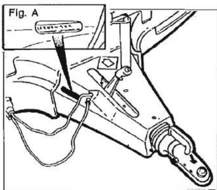
Record your caravan chassis number which can be found on the front offside section of the drawbar (Fig. A) or any of the eye level windows.
Make a note of this number in the space provided at the front of this handbook and make separate note of the number to keep safe at home.
Additional security
Consider fitting any device which might deter or prevent intrusion by thieves.

text_image
Fig. A ITEL-11CFig. A Chassis Number
A hitch lock cover prevents towing of the caravan.
A wheel lock prevents towing of the caravan and removal of the wheel.
Free crime prevention advice about securing your caravan, protecting your valuables, property marking, either at home or whilst on site, can be obtained from the Crime Prevention Officer through your local Police Station.

text_image
SERVICESConnection of Services 24
Water 25
Gas 26
Electricity 28
Services
Connection of services is dealt with under the separate headings.
In all cases users should become familiar with the equipment manufacturers' instructions.
Advice and leaflets, if not supplied with the caravan, can be obtained from the suppliers of the equipment.
Before making connections of any description to the caravan or its equipment, ensure that ALL equipment is turned off.

text_image
Scanned text of a document with dense, illegible horizontal lines and partial Chinese characters at the top.
WATER
Fill the fresh water container and place in a suitable position adjacent to the inlet.
Place the waste water receptacle in position, connect hoses to outlets and into waste water receptacle.
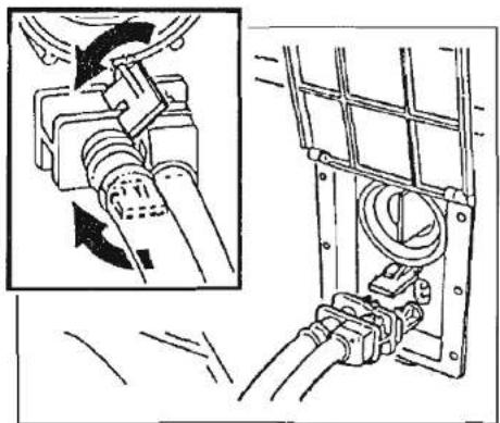
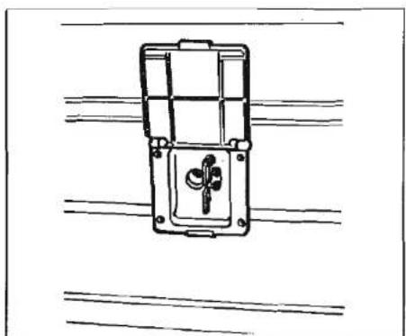
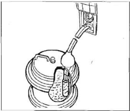
Raise lid of fresh water inlet, clean both the water socket and the plug of the pump assembly. To connect the pump simply align the plug with the socket and push into position. This makes both the water and electric connections (Fig. A and Fig. B (Rapide only)).
Turn the security clips to lock the connector plug in place (Figs. A & B). The pump system has been designed so that it cannot be fitted incorrectly. Place the submersible pump into the fresh water container ensuring that it is fully submerged before operating the system (Fig. C).
It should not be allowed to run without water nor should it be used to pump water of a temperature above 60^ C.
natural_image
Technical diagram showing mechanical assembly with arrows indicating direction and a magnified inset of a component (no text or symbols)Fig. A Carver Crystal Filter Inlet
natural_image
Simple line drawing of a mechanical switch or bracket with no text or symbolsFig. B Carver Compact Inlet (Rapide only)
natural_image
Diagram of a mechanical device with a lever and housing, no visible text or symbolsFig. C Fresh Water Container
Water Heating
The water system must be full before switching on the water heater. Ensure that water flows from the hot taps before operating the water heater either in gas or electric operation.
Services
natural_image
Line drawing of a car interior showing dashboard and seat structure (no text or symbols)Fig. A Gas Bottle Compartment
GAS
GENERAL INFORMATION
Gas Bottles
Bottled Liquified Petroleum Gas (LPG) is the most convenient portable source of fuel for your caravan.
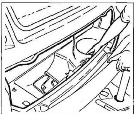
Make sure that heating and cooking appliances and the gas cylinders are switched off before you move the caravan. Regularly check flexible gas hose, joints and connections for tightness. Finally make sure that each gas appliance is working efficiently to the recommendations of the appliance manufacturers.
natural_image
Line drawing of a hand holding a mechanical component, no text or symbols presentFig. B Gas Regulator
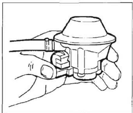
The regulator
The regulator (Fig. B) is a governing device which adapts the bottle pressure to one that suits the equipment in the caravan.
Note: Regulator valves should always be in the 'OFF' position when towing.
WARNING
Some industrial LPG appliances operate at high pressure and require a 'high pressure' regulator. This often has an adjusting handle on it. NEVER use such a regulator on a caravan.
Propane and Butane gas regulators are not interchangeable.
Cylinders and regulators are also not interchangable between different makes of gas cylinder.
Hoses
Hoses should be made from Neoprene, which is black and should conform to BS 3212. Rubber hosing should never be used. It is good practice to replace hoses annually, and a jubilee clip is a worthwhile addition to prevent accidental removal of the hose.
TYPES OF GAS
Butane
Butane is supplied in the U.K. in Green, Blue or Aluminium bottles.
All these have a male left hand thread except for Camping Gaz which has a special female right hand and Calor 7kg and 15kg and aluminium bottles which have a special clip-on connection.
Continental bottles usually have a male left hand thread similar to but not identical with U.K. butane.
Butane is suitable for use at temperatures down to 2°C but will not work below that.
Propane
Propane is supplied in Red, or partly red bottles which have a female left hand threaded connector.
Scandinavian countries use the same connector.
Germany and Austria supply propane with a male connection.
Propane will work at temperatures as low as - 40°C and is therefore suitable for all winter caravanning.
GAS SAFETY ADVICE
Facts about LPG
LPG is not poisonous.
Bi-products are harmless.
There is danger if all air and oxygen were excluded.
(Ventilation holes must be kept clear at all times).
LPG has been given a smell by the manufacturers in order to identify leaks.
Awning Spaces LPG Appliance Exhaust
There is no danger of pollution of an enclosed awning space by the LPG exhaust from a refrigerator venting into it.
Space heaters may produce sufficient exhaust to pollute the awning space, if it is totally enclosed, from a general comfort, smell and hygiene point of view. In the extreme case there could be a build up of carbon dioxide to a dangerous level.
Caravan owners are advised to allow some fresh air circulation in the awning space when such appliances are in use.
PRECAUTIONS
a) Never look for a leak with a match. Always use a soap solution or its equivalent when testing connections. Do not operate any electrical apparatus whatsoever, especially light switches. If the leak is not obvious, the caravan should be evacuated and qualified personnel consulted.
b) Avoid naked lights when connecting or changing a cylinder.
c) Check the flexible hose frequently.
d) The gas is heavier than air and therefore sinks to the lowest point.
e) Keep bottle gas containers outside (and protected against frost). If they must be kept inside make sure they are well away from heat.
Ventilation
All ventilation complies with BS 4626 and vents should not be obstructed in any manner as this could lead to insufficient fresh air. In this case the confined atmosphere becomes depleted of oxygen which leads to the formation of the highly poisonous gas 'carbon monoxide'. Carbon
Services
Monoxide is odourless, colourless and tasteless and will rapidly cause unconsciousness and death with little or no warning prior to collapse. THERE IS NO DANGER WHEN ADEQUATE VENTILATION IS PROVIDED.
Roof-mounted Flue installations
All flue installations should be inspected. once a year throughout their length for corrosion. Flues should be replaced if any sign of perforation is found. Ensure that the replacement is of an approved type.
CONNECTION
Ensure that the gas regulator is correctly connected to the gas cylinder in gas bottle compartment and that the hose is tight. Before turning on the gas supply, ensure that all gas operated equipment in the caravan is turned off.
Services
ELECTRICITY
As with electricity in the home, care must be exercised when handling mains electricity.
Your attention is drawn to the following notice as laid down by the Institute of Electrical Engineers.
INSTRUCTIONS FOR ELECTRICITY SUPPLY
On arrival at caravan site
- Before connecting the caravan installation to the mains supply, check that
(a) the mains supply is suitable for your installation and appliances, i.e. whether it is a.c. or d.c. and whether it is at the correct voltage and frequency,
(b) your installation will be properly earthed. Never accept a supply from a socket outlet or plug having only two pins, or from a lighting outlet, and
(c) any residual current device (earth leakage circuit breaker) in the mains supply to the caravan has been tested within the last month.
In case of doubt, consult the site owner or his agent.
-
MAKE SURE THAT THE SWITCH AT THE SITE SUPPLY POINT IS OFF.
-
Lift the cover of the electricity inlet provided on the caravan, and insert the connector of the supply flexible cable.
- Remove any cover from the socket outlet provided at the site supply point, and connect the plug at the other end of the supply flexible cable to this. Switch on the main switch at the site supply point.
On leaving caravan site
- Reverse the procedure described in Paragraph 3 and 4 above.
IT IS IMPORTANT THAT THE MAIN SWITCH AT THE SITE SUPPLY POINT SHOULD BE SWITCHED OFF, THE SUPPLY FLEXIBLE CABLE DISCONNECTED, AND ANY COVER REPLACED ON THE SOCKET OUTLET AT THE SITE SUPPLY POINT BEFORE DISCONNECTING THE FLEXIBLE CABLE FROM THE CARAVAN. IT IS DANGEROUS TO LEAVE THE SUPPLY SOCKET OR SUPPLY FLEXIBLE CABLE LIVE.
Periodically
- Preferably not less than once a year, the caravan electrical installation should be inspected and tested and a report on its condition obtained as prescribed in the Regulations for Electrical Installations, published by the Institute of Electrical Engineers.
IN CASE OF DIFFICULTY CONSULT AN APPROVED ELECTRICAL INSTALLATION CONTRACTOR (WHO MAY BE THE LOCAL ELECTRICITY COMPANY). IT IS DANGEROUS TO ATTEMPT MODIFICATIONS AND ADDITIONS YOURSELF. LAMPHOLDER—PLUGS (BAYONET-CAP ADAPTORS) SHOULD NOT IN ANY CIRCUMSTANCES BE USED.
OVERSEAS CONNECTION
Note: Connection to a mains voltage supply OVERSEAS requires particular attention.
Care must be taken when connecting supplies abroad since the supplies can be of REVERSE POLARITY.
The significance of REVERSE POLARITY is that when equipment is switched off it may not be electrically isolated.
The only certain way of making equipment safe is to unplug it.
If electrical polarity indication is not included in your caravan electrical equipment (Rapide Models), it is useful to have a means of checking polarity of the mains supply, especially when touring overseas. There are available several proprietary makes of equipment for testing polarity.
If it can be achieved, it is preferable to connect live to live, and neutral to neutral to maintain full electrical protection.

natural_image
Black-and-white photo of a textured surface with horizontal striations and no visible text or symbolsServices
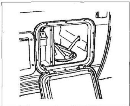
natural_image
Technical line drawing of a vehicle interior frame with no visible text or symbolsBattery Box (External)
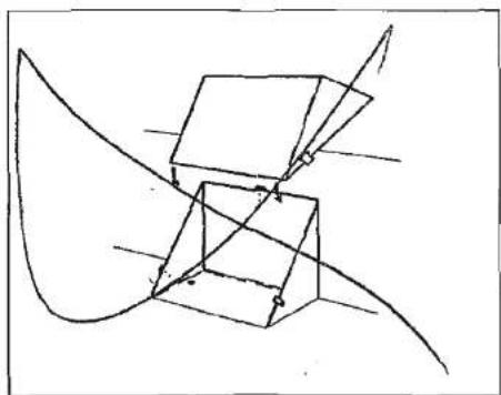
natural_image
Abstract line drawing of intersecting planes and cubes (no text or symbols)Battery Box (Internal)
Where internal battery box is fitted, ensure vent pipe is inserted through grommet provided.
WIRING OF CONNECTING CABLE AND CARAVAN MAINS INLET
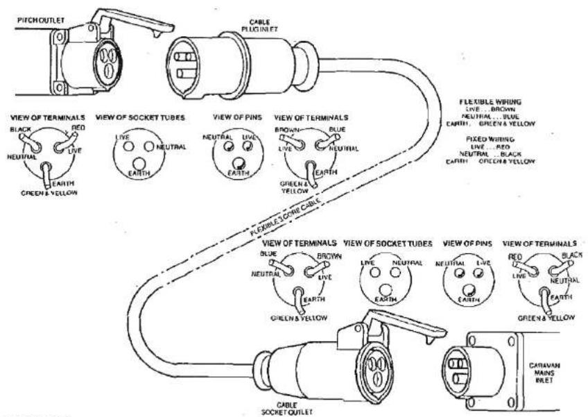
text_image
PITCHOUTLET VIEW OF TERMINALS BLACK RED NEUTRAL LIVE EARTH GREEN & YELLOW VIEW OF SOCKET TUBES LIVE NEUTRAL EARTH VIEW OF PINS NEUTRAL LIVE EARTH VIEW OF TERMINALS BROWN BLUE LIVE NEUTRAL EARTH GREEN & YELLOW FLEXIBLE WIRING LIVE ... BROWN NEUTRAL ... BLUE EARTH ... GREEN & YELLOW FIXED WIRING LIVE ... RED NEUTRAL ... BLACK EARTH ... GREEN & YELLOW VIEW OF TERMINALS BLUE BROWN NEUTRAL LIVE EARTH GREEN & YELLOW VIEW OF SOCKET TUBES LIVE NEUTRAL EARTH VIEW OF PINS NEUTRAL LIVE EARTH VIEW OF TERMINALS RED BLACK LIVE NEUTRAL EARTH GREEN & YELLOW CABLE SOCKET OUTLET CARAVAN MAINS INLETWARNING
IT IS ESSENTIAL THAT CONNECTIONS ARE MADE EXACTLY AS SHOWN. IF TERMINAL MARKINGS ARE NOT IN ACCORDANCE WITH THE DIAGRAM THEY MUST BE IGNORED. IF IN DOUBT CONSULT A QUALIFIED ELECTRICIAN.
THE LEGAL MAXIMUM LENGTH OF THE MAINS INLET CABLE IS 25 METRES. WHEN IN USE IT MUST BE FULLY UNCOILED.

text_image
ELECTRICAL EQUIPMENTPower Management System - PMS 4 32
Fault Finding 33
General 33
KT9S2 Distribution Panel 34
KT9/640 Distribution Panel 34
Mains Unit CEC 225 35
Transformer/Charger Unit KT12SM 35
Operating Instructions 36
Switches 36
Battery 37
Electrical Supply 38
Electrics
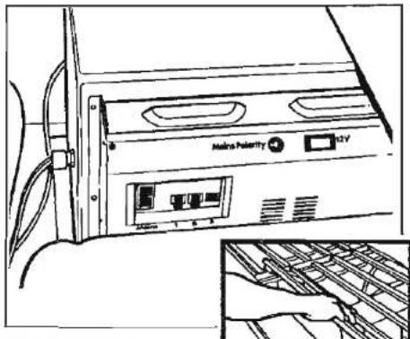
text_image
Molina Pulsor H2VFig. A P.M.S.4
POWER MANAGEMENT SYSTEM
The Power Management System PMS 4 is a fully automatic mains and 12 volt DC distribution and battery system featuring a 40 Amp 2 Pole residual current device (RCD), and three miniature circuit breakers (MCB's) for mains output protection and a 12 Amp DC Transformer Charger. All outputs are on sockets, making the unit simple to install and operate and requiring minimum attention in use.
MAINS VOLTAGE CONTROL
The PMS is designed to operate on a mains supply of 220-240V AC 50Hz.
The 40A 2 Pole RCD gives protection against earth faults and is also the main switch.
The MCB's are provided to give overload protection for the mains circuits.
BATTERY CHARGER
This is controlled by the illuminated ON/OFF switch, mounted on the top of the panel and marked 12V.
POLARITY INDICATOR
This is the red pilot light mounted on the upper front panel and when illuminated indicates the polarity of the mains input is reversed and needs to be corrected.
MAINS INPUT AND OUTPUT
Mains input is via the 2.5mm × 3 core flex. Output is via the 9 Pin and 6 Pin Sockets.
12 VOLT DISTRIBUTION
A built in transformer/battery charger in conjunction with a 12 volt battery supplies the 12 volt circuits via the DC output fuses numbered 1-6.
Output is via the 12 Pin and 15 Pin Sockets.
OPERATING INSTRUCTIONS
- Disconnect Car/Caravan 7 Pin plugs and towing coupling.
- Ensure mains switch is OFF.
- Connect the caravan to the mains supply with the hook-up cable.
- Check polarity indicator light, if correct (indicator OFF) proceed to
No.5. If not correct (indicator ON) reverse input polarity and repeat operation from 3 above.
- Switch the main switch ON.
- Switch the MCB's to ON.
- Switch the battery selector switch to the mid position, this will isolate the batteries from the DC electrical system.
- Switch charger 12V switch ON (illuminated).
- The PMS is now in full operation and will power the 12V DC electrical system i.e. lights etc. In order to charge the caravan battery the battery selector switch should be switched to the appropriate position, i.e. the caravan (AUX) position, should you need to charge the car battery then you should position your select switch to the car (MAIN) battery position.
- When drawing 12 amps the unit will enter "current limit" mode. This means that any attempt to draw more current from the unit will be refused. This feature is especially useful for charging a battery that is excessively discharged. It also prevents damage to the unit, it's associated wiring and the 12 volt installations.
- When the battery is fully charged and there are no 12V power supply requirements the charger should be switched off.
Electrics
RCD TEST BUTTON
This should be operated at regular intervals in order to check and ensure effective operation of this facility.
See the label fitted adjacent to the PMS unit in your caravan and also the RCD/MCB section in these instructions.
RCB/MCB SECTION
These components are designed to give both overload and earth leakage protection for the electrical supply in your caravan. The MCB's are better described as mechanical fuses. In the event of an overload situation, the circuit they supply is automatically switched to the OFF position. After elimination of the fault the MCB should be re-set by switching back on again (against the spring pressure) in an upward direction.
Normally these MCB's should be left in the ON position.
The RCD is fitted to provide protection against earth faults and possible electrical shock. In the event of an earth fault which would cause a current leakage to earth, either directly or via the human body, the unit should immediately trip and switch OFF the supply. Only after elimination of the fault will it be possible to re-set the RCD to the ON position and so restore the supply again, the ON position being
upwards against the spring pressure.
Periodically it is necessary to test the operation of the RCD. This is achieved by ensuring that it is in the switched ON position with an electricity supply connected and by pressing the test button marked 'T'. The unit should immediately switch to the OFF position. Provided this happens all is correct and the switch should be returned to the ON position (upwards) to restore the supply back to normal.
The RCD also acts as the main switch for the unit and if it is required to switch off all circuits in the caravan this can be achieved by switching the RCD to OFF.
OPERATING TEMPERATURES
The PMS may be warm to the touch when the charger is operating and this temperature will vary with the charge rate. It is therefore important that adequate ventilation is maintained to the area surrounding the unit.
FUSES
Replacements must be made only with fuses of equivalent values, and of the same type as the originals. Correct values are clearly marked on the fuses. Never use a fuse of higher rating than that stated.
FAULT FINDING
- Mains Supply
If mains supply is not available when Mains Switch and MCB's are switched on, check supply at site distribution and/or mains lead and connections. - Earth Faults or MCB Tripped See RCD/MCB Section.
- Charger Switch fails to Illuminate Check mains supply as for No.1 and 2.
- Battery Discharged or not charging with Charger On Check battery terminals.
- 12 Volt Distribution Circuit Failure Check and replace relevant DC output fuse as required.
- Consult the manufacturers regarding any further difficulties in particular those related to mains voltage section,
- There are no user-serviceable or replacement parts in the PMS. All service of this nature should be referred to the manufacturers. (See p. 37)
Note: Never use a mains supply lead whilst coiled. Always uncoil the full length before connecting to the supply.

text_image
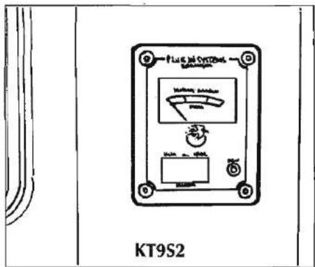
P Lu G. Jai Cyt12nab KT9S2KT9S2 DISTRIBUTION PANEL
The KT9S2 Distribution panel has the following facilities:
- Battery Condition Indicator
- Battery Selector Switch
- Pump ON Indicator
Operation
- Select CAR or CARAVAN battery supply source required by the three position switch.
- Check that the meter needle moves into the yellow or green sectors of the scale, indicating satisfactory battery charge state.
text_image
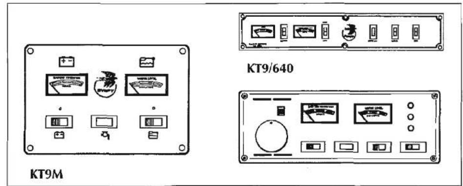
KT9M KT9/640- 12 volts DC is now distributed to all caravan circuits.
- The central OFF position on the selector switch ensures that both car and caravan battery supplies are switched off. If however mains supply is connected via the charger unit, 12 volts supply will be available direct to power the 12 volt system in the caravan.
KT9/640 DISTRIBUTION PANEL
The KT9/640 Distribution Panel has the following facilities:
Switches
WATER LEVEL
This switch, when pressed indicates the level of water available in the tank.
LIGHT
Overhead fluorescent DC light.
FAN
Integral extractor fan.
PUMP ON
When illuminated, the water pump is in operation.
CAR/VAN
Same as for operation of the KT9S2
Distribution Panel above.
text_image
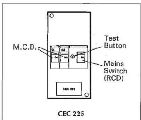
M.C.B. Test Button Mains Switch (RCD) CEC 225MAINS UNIT CEC 225 (Rapide only)
- This unit is designed to give both overload and earth leakage protection for the electrical supply in your caravan.
- The MCB's (Miniature Circuit Breakers) are better described as mechanical fuses, which, in the event of an overload situation in the circuit which they supply, will automatically switch to the OFF position. After elimination of the fault the MCB is re-set by switching back on again (against the spring pressure) in an upwards direction.
-
In normal operation these MCB's should be left in the ON position.
-
A Residual Current Device (RCD) is fitted to provide protection against earth faults and possible electrical shock. In the event of an earth fault causing a leak of current to earth, either directly or via the human body, the unit should immediately trip, and switch OFF the supply. Only after elimination of the fault will it be possible to re-set the RCD to the ON position and so restore the supply again. The ON position is upwards against the spring pressure.
- Periodically it is necessary to test the operation of the RCD. This is achieved by ensuring that it is in the switched ON position with an electricity supply connected. By pressing the test button marked 'T' the unit should immediately be switched to the OFF position. Provided this happens all is correct and the switch should be returned to the ON position (upwards) to restore the supply back to normal.
- The RCD also acts as the mains switch for the unit and, if it is required to switch off all circuits in the caravan, this is done by operating the OFF/ON switch on the RCD.
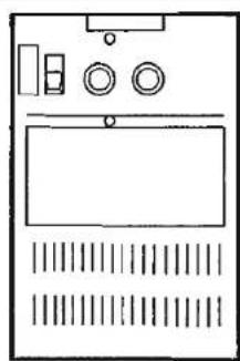
TRANSFORMER/CHARGER UNIT KT12SM
- The KT12SM transformer/charger unit from Plug-In-Systems is a fully
Electrics
natural_image
Simple line drawing of a device casing with buttons and ventilation grilles (no text or symbols)KT12SM
mains to 12 Volt DC transformer unit combining power and safety to give the ultimate in 12 Volt DC power supplies. It is specifically designed for caravan and motorhome installations, simple to install and requiring minimal attention in use.
The unit incorporates important safety features:
CURRENT LIMITING (12A) SHORT CIRCUIT PROTECTION REVERSE POLARITY PROTECTION
The KT12SM power unit provides rectified and smooth DC and is designed not only to operate as a battery charger but also as an
Electrics
alternative power supply should a 12 Volt DC battery not be present in circuit. It is however recommended that a good quality LEISURE battery be installed.
2. Operation
2.1 Once the unit is connected to 240 Volt mains supply and 12 Volt circuits its operation is fully automatic once switched on.
2.2 When used as a battery charger any load placed on the 12 Volt system will be shared by the battery and the unit.
2.3 When used as a 12 Volt DC power supply with no battery in circuit, the KT12SM will supply an output suitable for use with pump, lighting, TV, radio etc.
3. Protection
3.1 The unit is capable of providing up to 12 Amps. When drawing 12 Amps the unit will enter "Current Limit" mode. This means that any attempt to draw more current from the unit will be refused. This feature is especially useful for charging a battery that is excessively discharged. It also prevents damage to the unit, it's associated wiring and the 12 volt installations.
3.2 A 15 Amp DC output fuse is provided for safety reasons. In practice, because
of the unit's unique "Current Limit" mode, this fuse should rarely require attention.
3.3 Under normal circumstances the total load required by caravan equipment should not produce an overload situation.
4. General information
4.1 Mains input to the unit is via a 0.5mm 3 core flexible cable permanently connected to the unit.
4.2 Mains supply to the KT12SM unit should be via a mains unit, to give both earth leakage and overload protection, and must be fused at 5 Amps maximum.
4.3 For optimum performance and safety it is essential that only a good quality CARAVAN battery is used in conjunction with the KT12SM. A normal car battery is NOT suitable.
4.4 One of the most common causes of caravan battery failure is for the battery to be discharged below the recommended level of approximately 10 Volts and therefore causing one or more of the cells to fail.
4.5 Provided the appropriate relay is fitted to your car and the connection is made via the 12S plug and socket, it is possible to charge the caravan battery whilst towing. This is recommended in
order to keep the battery in a fully charged condition.
4.6 The KT12SM unit is designed for use in conjunction with a KT series control panel which has a car/caravan battery selector switch. The facility for drawing 12 Volt supply from the car battery is intended for standby situations only and care should be taken not to run the car battery too low. It is not recommended to leave the KT12SM switched on for long periods of time (i.e. 3 months) when the 12 Volts systems are not being used.
The KT12SM will automatically charge the battery whilst giving 12 Volt power to all 12 Volt systems in the caravan, when the mains system is connected to a 220/240 Volts supply.
Apart from a short top-up charge prior to each use of the caravan it should not be necessary to leave the KT12SM switched on when the caravan is not being used.
4.7 When using a generator to supply the KT12SM ensure that the actual generator output voltage does not exceed it's own rated generator output voltage and the rated input voltage of the KT12SM otherwise internal damage of the KT12SM could occur.
4.9 Ensure that the KT12SM is securely fastened and NOT left free standing.
Electrics
4.10 Connection of the KT12SM to the mains supply should be in accordance with the Regulations for Electrical Installations, 16th Edition (IEE Wiring Regulations), 1981 published by the Institution of Electrical Engineers. (SEE ALSO -GENERAL INFORMATION - SECTION 2).
4.11 The battery should be positioned in a compartment vented to the outside due to the possibility of explosive gases being present.
BATTERY
It is recommended that a good quality leisure battery is always in circuit when the system is in use.
A deep cycling heavy duty 12v battery should be purchased to provide power for lights and other electrical appliances. A proprietary brand leisure battery with either a 60 or 90 or 110 amp capacity is recommended. (It must have tube venting capability for internal battery boxes).
It should be remembered that batteries suitable for the electrical demands of a caravan differ in design from those for use with a car, and whilst the system may operate with a car battery it is strongly recommended that only a leisure type battery, maintained in good condition is used. The battery should be kept topped up at all times.
The battery should be positioned in a compartment vented to the outside and should be properly secured. When connecting the battery, ensure that the correct polarity is observed (black is negative and red is positive) and that the terminals are securely fastened (Crocodile Clips are not recommended).
Under normal circumstances it should not be necessary to remove the battery other than for routine inspection of terminals and "topping up".
WARNING
Explosive gases may be present at the battery. Take care to prevent flames and sparks in the vicinity.
Your caravan has been fitted with an in-line fuse between the battery terminal and strip connector. It is recommended that the fuse rating fitted in this location does not exceed 16 amps.
SUPPORT SERVICE
PLUG-IN SYSTEMS LIMITED PROVIDE AN ON-CALL SERVICE FOR WARRANTY OR NON-WARRANTY REPAIRS.
IF YOU WISH TO TAKE ADVANTAGE OF THIS SERVICE FOR PLUG-IN-SYSTEMS ONLY
Telephone (0482) 652523 and ask for PRODUCT SUPPORT SERVICE.
Electrics
12 VOLT ELECTRICAL SUPPLY
If your car is fitted with the appropriate relay, please note the following points:
- The caravan battery will be charged by the car charging system independently of the distribution panel (KT9S2 or KT9/640).
- Whilst towing, the battery selector switch on the distribution panel should be set to the centre position.
- When on site, whether hooked up to a mains supply or not, the selector switch on the distribution panel should be set to the "caravan" position to activate the caravan 12 volt system.
-
If the caravan battery level is "low", power for the caravan 12 volt system can be obtained from the car battery, by connecting the 12S (grey) plug to the car, and setting the distribution panel selector switch to "car". This will draw power from the car battery and care should be taken not to reduce the level of the car battery so low that the car engine cannot be started. (The battery level indicator in the caravan distribution panel will show the condition of the car battery in these circumstances).
-
When the car and caravan are connected through the 12N and 12S plugs and the car engine is running, 12 volt power will be supplied to the refrigerator, provided the refrigerator selector switch is set to the 12v position, regardless of the position of the distribution panel selector switch. (See para. 2 above).

text_image
FITTED EQUIPMENTCarver Crystal Filter Water System 40
Whale Water Pump 40
Cascade 2GE Water Heater 40
Operating Instructions 40
Frost Precautions 41
Refrigerator 41
Controls 41
Model RM212 42
Model RM2260 43
Model RM2262 44
Model RM2267 45
Travel Catch 46
Maxol Monte Carlo 3000 Oven 47
Cramer Hob and Grill 47
Carver 1800 Heater 48
Carver 2000 Heater 48
Carver 3000 Heater 48
Room Temperature 49
Carver 3000 Auto & 5000 49
Central Heating 50
Blown Air Fan 50
Butterfly Outlets 50
Thetford Cassette Porta Potti 51
Bedding 55
Single Beds Assembly 55
Bunks (side) 56
Double Bed Assembly 56
Bunks (rear) 57
Cassette Blinds 58
Flyscreens 58
Tables 59
Awning Points 60
Ash Framed Doors 60
Fitted Equipment
Equipment Specification
For details on type of equipment fitted in your caravan, please refer to Fitted Equipment Lists on Pages 87 & 88.
IMPORTANT
To maximise the use and life of all fitted equipment in your Swift Caravan it is essential that any accompanying manufacturers' literature is read fully. All recommended maintenance and preparation procedures should be followed. The information provided in this handbook is only intended as a guide. If in any doubt consult your Swift appointed dealer, particularly before attempting to install EXTRA EQUIPMENT.
THE CARVER CRYSTAL FILTER WATER SYSTEM
The Carver Crystal Filter is a high quality product designed to bring water to your caravan in a convenient and efficient manner. Spring and Winter Preparation of the filter unit is essential. Consult manufacturer's information.
WHALE WATER PUMP
The Whale Superline 99 pump is a non self priming intermittently rated centrifugal pump which draws approximately two amperes from a 12 volt battery and therefore maximum continuous operation should not exceed 15 minutes.
The pump should not be run without water and should not be used to pump water of a temperature above 60^ C.
text_image
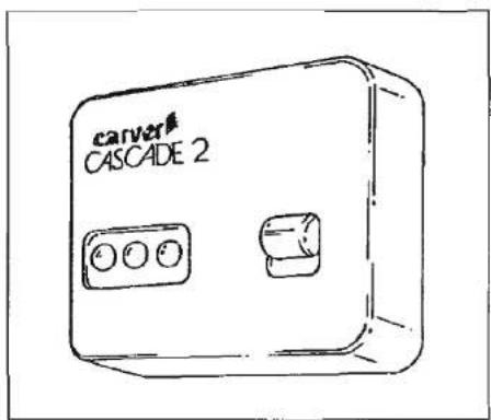
carver CASCADE 2CASCADE 2 GE WATER HEATER OPERATING INSTRUCTIONS
The gas side of the Cascade 2 GE Water Heater is operated by this remote controller.
BEFORE SWITCHING ON the gas burner or the mains immersion heater make sure that water flows from the hot taps. This indicates that the water heater is full.
TO OPERATE THE HEATER ON GAS
- CHECK that the gas and 12 volt D.C. electrical supplies have been connected and turned on.
-
SWITCH THE WATER HEATER ON at the wall switch. The green light will come on and remain on.
-
THE GREEN LIGHT indicates that the heater is operating satisfactorily and does not refer directly to the burner operation.
- THE YELLOW AND GREEN LIGHTS on together indicate that the voltage of the power supply to the heater is too low. The heater is automatically switched off until the voltage is high enough.
- THE RED AND GREEN LIGHTS on together show that the burner has failed to light in the 10 second ignition period. This is usually due to failure of the gas supply or, in the case of a new installation, air in the gas pipes. Switch off and on again, which resets the controller and initiates a new ignition sequence. To clear air from the gas lines, several repetitions may be required.
TO OPERATE THE HEATER ON MAINS ELECTRICITY
The immersion heater switch is located in the vicinity of the Cascade Water Heater. With the caravan connected to site mains, electrical power may be used instead of gas to maintain a supply of hot water.
For quick warm-up both gas and electrical supplies may be used, but for maintenance use only one or the other.
The immersion heater takes approximately 3 amps when heating and this load must be taken into account if the site supply is limited. (5 amp fuse fitted in switch).

natural_image
Grayscale abstract texture with horizontal bands and no visible text or symbols
natural_image
Technical line drawing of a mechanical component with threaded shaft and mounting holes (no text or symbols)CASCADE 2 and CASCADE 2 GE:
Frost Precautions
IMPORTANT:
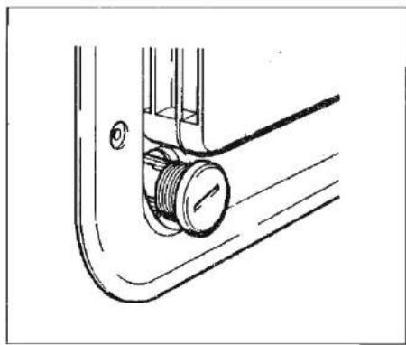
During periods of freezing weather, when the caravan is unheated, the Cascade 2 GE MUST be drained to prevent frost damage. The drain plug which is on the outside of the flue cowl, should be unscrewed to permit draining. When the end of the drain plug thread is reached the plug can be pulled out a small distance, yet still be retained in the thread and permit draining to occur. To allow the system and tank to drain effectively, open all hot and cold taps while the heater is still warm. Leave the drain plug and taps
open for AT LEAST 30 MINUTES, to ensure complete draining.
If your system also includes a Crystal Water System, make sure that the pump is emptied of any water and unscrew the filter cartridge to permit it to drain.
To recommission the heater: Close cold taps and drain plug and reconnect the pump. Let the system fill with water until water flows steadily from the hot taps. About two gallons of water will be required. Once the hot taps are flowing freely close them and switch on the Cascade 2 GE heater.
natural_image
Line drawing of a door with ladder and guardrail, no text or symbols presentREFRIGERATOR
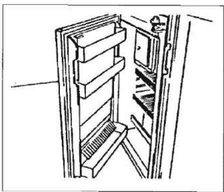
When using your refrigerator for the first time, it is advisable to wash the interior and its accessories.
When the caravan is on tow, the refrigerator should be operated electrically, i.e. from the 12V battery in the towing vehicle, and not by means of bottled gas.
CONTROLS
The refrigerator can be run on either 240 V, 12 V or LP gas. Changing between these modes of operation is carried out by means of the controls shown on the relevant control panel.
Caution!
Only use one source of energy at a time.
Fitted Equipment
text_image
MODEL RM212 C B D AMODEL RM212
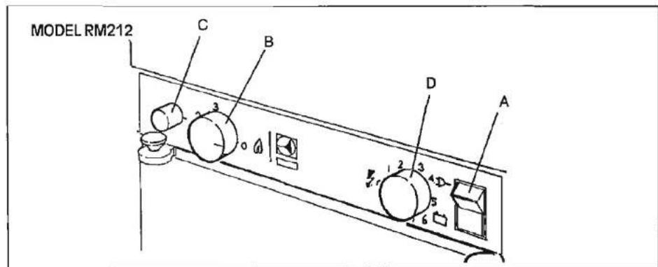
The bottled gas equipment includes a Piezo crystal lighting device which creates a spark over the burner when the button (C) is pushed in fully. No batteries or flints are required to operate this lighter.
L.P. GAS OPERATION - Lighting the burner
- Set the selector switch (A) to 'O', i.e. is in its centre position. Ensure that gas is available from the bottle and turn on any taps in the supply to the refrigerator.
- Turn the gas control knob (B) so that '3' is opposite the indicator mark.
- Push in fully the gas control knob (B)
for about 5 seconds to allow air to clear from the pipe line. (When starting initially, or after changing a gas bottle, it may be necessary to push in the knob appreciably longer to clear all the air. Do not, however, allow too much gas to accumulate around the burner as an over-rich gas/air mixture may be difficult to ignite).
- Still pressing in the knob (B), push in the button (C) which operates the Piezo igniter, several times in quick succession. (A click should be heard each time the button is pushed in). Continue to press in the gas control knob (B) for a further 15 seconds to allow time for the thermocouple tip
(over the burner) to heat up. 5. Release the gas control knob then check that the burner is alight by looking directly through the flame viewer located inside the cabinet at the rear left-hand lower corner. If the burner has not lit, repeat the lighting procedure.
Note:- The refrigerator has a flame failure device which will automatically shut off the gas to the burner if the flame is blown out. While the knob (B) is being pressed in, this device is temporarily inoperative.
ELECTRIC OPERATION
Set the gas control knob (B) to the 'O' position (off).
Fitted Equipment
240 V Operation
Set the voltage selector switch (A) to (top of switch pushed in).
Knob (D) is thermostatic control for 240V operation only
12 V Operation
Set the voltage selector switch (A) to (bottom of switch pushed in).
It is important to understand that 12 volt operation is only intended to be used while the car engine is running and is charging the battery, otherwise the car battery may be discharged to a point where it will not restart the engine. (The current drain at 12V is 8 amps minimum). When at rest for more than a short period, the caravan should be levelled and the refrigerator switched over to mains voltage, if available, or the 12V supply switched off and the refrigerator started up on bottled gas.
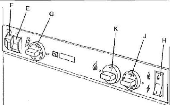
MODEL RM2260
OPERATING INSTRUCTIONS
Two rocker switches are used to select the electric power supply, one for 240 V (E) and one for 12 V (F).
Refrigerator temperature is controlled by a thermostat (G) when the refrigerator runs on 240 V.
The electric igniter (H) discharges sparks
MODEL RM2260
text_image
F E G K J Hover the burner when the control is depressed.
Refrigerator temperature is controlled by a thermostat (J) when the refrigerator runs on LP gas. Please note that the thermostat has no off position.
The gas supply to the refrigerator should be shut off by means of a gas shut off valve close to the refrigerator.
The refrigerator is fitted with a combined gas cock/safety device (K) which automatically shuts off the supply of gas to the burner when the flame goes out.
An indicator lamp on the control panel flashes when the automatic igniter attempts to light the burner. Otherwise the lamp is normally off.
STARTING THE REFRIGERATOR
Choose ONE source of power and follow the relevant operation details below.
LP GAS OPERATION
- Make sure that the refrigerator electric power supply is switched off.
- Make sure that all valves between the gas container and the refrigerator are open.
- Turn on the gas control (J) to position 8.
- Turn on the electric igniter (H). A ticking sound will be heard and the lamp (H) will start flashing.
Fitted Equipment
MODEL RM2262
text_image
F E L M N- Turn on the gas supply by pressing knob (K) and turning it to the '●' position.
- When the lamp stops flashing the flame is alight.
- Keep the flame failure monitor button depressed for a further 15-30 seconds.
- To terminate gas operation or when changing to 240V or 12V operation, turn knob (K) to the 'O' position:
240 V operation
- Turn off the gas by means of the gas control.
- Set the 240 V rocker switch (E) to 1 and the 12 V rocker switch (F) to 0.
12 V operation
- Turn off the gas by means of the gas control.
- Set the 240 V rocker switch (E) to 0 and the 12 V rocker switch (F) to 1.
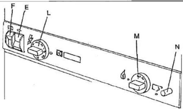
MODEL RM2262
This model is fitted with a piezoelectric igniter and is operated in exactly the same manner as Model RM2260 except for GAS operating instructions 3 to 7 which are replaced by the following:-
- Depress and turn the gas control (L) to position 3.
- Depress the safety device control (M) and hold it down whilst depressing the
piezoelectric igniter button (N) several times in quick succession.
- Check the flame viewer to see whether the flame is alight.
- Keep the safety device control depressed for a further 15-30 seconds.
- Release the safety device control and again check to see that the flame is alight.

natural_image
A horizontal line of uniform gray lines with no text or symbols, indicating a constant baseline or reference value.
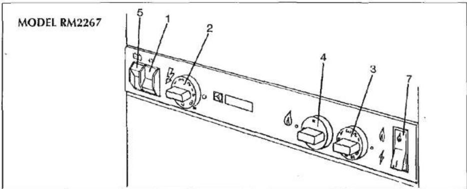
text_image
MODEL RM2267 5 1 2 3 4 3 7MODEL RM2267
The refrigerator can be run on either 240V, 12V or LP gas. Changing between these modes of operation is carried out by means of the controls on the control panel.
Two rocker switches are used to select the electric power supply, one for 240V (1) and one for 12V (5). Refrigerator temperature is controlled by a thermostat (2) when the refrigerator runs on 240V.
The gas supply is turned on/off by means of the knob (4). The gas flame is electronically lit, monitored and relit if necessary. For this the toggle switch (7) should be 'on' during gas operation. An indicator lamp in the switch flashes when the automatic igniter attempts to light the burner.
LP gas operation
- Open the shut-off valve of the gas bottle.
- Check that the switches for mains and 12V operation are off.
- Turn on the gas supply by pressing the (4) knob and turning it to the ● position.
- Set the thermostat knob (3) to the highest setting.
- Set switch (7) to 1. A light in the switch should now start to flash, indicating
that sparks are being generated at the burner.
6. Press the (4) knob. This opens the flame failure device and allows gas to flow to the burner.
7. When the flame lights, the sparking stops automatically and the switch stops flashing.
8. Keep the (4) knob pressed for a further 10 to 15 seconds to activate the flame failure device, then release it.
The flame can be observed in a viewing glass inside the fridge, bottom left.
To terminate gas operation, turn knob (4) to 'O' and set switch (7) to 'O'.
Fitted Equipment
240V Operation
- Turn off gas or 12V operation when applicable.
- Turn the knob (2) of the thermostat to its highest (coldest) position.
- Set switch (1) to position 1. The switch will light up green when the power supply is connected.
12V Operation
Only operate the fridge on 12V when the engine of the vehicle is running, otherwise your battery will discharge.
- If applicable turn off the gas operation.
- Set the 240V rocker switch (1) to 'O' and the 12V rocker switch (5) to I.
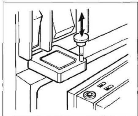
natural_image
Technical line drawing of a mechanical assembly with a central component and directional arrows (no text or symbols)TRAVEL CATCH
All models are fitted with a travel catch to keep the refrigerator door securely closed when the vehicle is on the move. Remember always to push the catch down so that its lower end fully engages the plastic bush in the top of the door, before moving off.
FURTHER DETAILS
Consult the accompanying literature to obtain the full benefit of your Electrolux Refrigerator.
In the event of failure, contact Electrolux Service. Details of which can be found in your Yellow Pages Directory.

natural_image
Pure horizontal line pattern without any text, numbers, or symbols
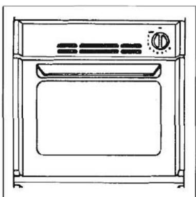
natural_image
Line drawing of a standard open oven with control panel and door (no text or symbols)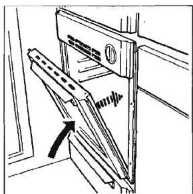
natural_image
Technical line drawing of a door latch mechanism with an arrow indicating motion (no text or symbols)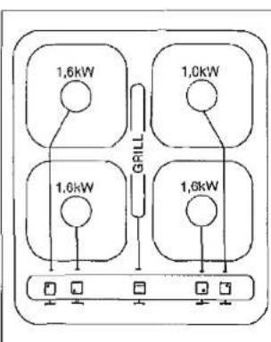
text_image
1,6kW 1,0kW 1,0kW 1,6kW GRILL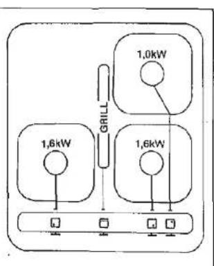
text_image
1,6kW 1,6kW 1,0kW GRILLMAXOL MONTE CARLO 3000
LIGHTING THE OVEN
To light the oven slightly depress the control knob and rotate to the ignition position, depress fully, hold and light burner with a match. Keep the control knob depressed for 20 seconds, release the control knob, the required setting can now be achieved by rotating the control knob. The oven door should then be closed slowly to avoid the possibility of the flame being extinguished.
MAXOL MONTE CARLO 3000i
To light the oven, open the oven door fully, turn the control knob to the required setting, depress the control knob and operate the igniter, situated on the hob, until the burner lights. When the burner is lit continue to depress the control knob for 20 seconds then release.
MAXOL MONTE CARLO 3000Ti
Operation is the same as for the 3000i but this oven is thermostatically controlled.
IMPORTANT:
If aluminium foil is used in the oven then it must not be allowed to block the oven flue or smother the burner. The flue outlet is situated in the centre of the oven compartment roof at the back.
Best results will be obtained by pre-heating the oven for about 15 minutes.
- CRAMER HOB & GRILL
USERS INSTRUCTIONS
Note: all these units are available in left and right hand versions.
WARNING
Place large pans on the front burners to avoid heat build-up at the rear of the unit.
WARNING
When using the grill make sure the hob cover is raised.
The appliance is provided with self locking taps.

To turn on gas, turn control knob to the position and apply a source of ignition.
Fitted Equipment
Automatic Ignition
Turn the control knob of the required burner to the high position and press the spark ignition switch simultaneously. Hold the switch until the burner ignites. When the burner flames are established any rate may be selected between
full

and low

To turn off the gas, turn the knob clockwise to the end position.
The grill must be lit manually.
For information on how best to use the oven and hob refer to manufacturer's instructions.

HEATING
CARVER 1800
- BEFORE LIGHTING THE HEATER
1.1 Ensure that the gas is turned on. - LIGHTING THE HEATER
2.1 Turn the gas control knob fully anti-clockwise and then press down. Immediately press the ignition button several times.
2.2 Check through the viewing window on the lower half of the case that the burner is alight.
2.3 After the burner has lit continue to
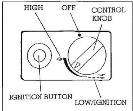
text_image
HIGH OFF CONTROL KNOB IGNITION BUTTON LOW/IGNITIONhold the gas control knob down for 30 seconds. This is to operate the flame failure safety device within the gas control.
2.4 The control knob can now be adjusted to the required comfort setting between the ignition/low and the high positions.
2.5 If the burner fails to remain alight or if it is extinguished due to abnormal wind conditions the heater will shut down to a safe condition. After shut down always WAIT 3 MINUTES before attempting to relight the heater.
- TURNING OFF THE HEATER
3.1 Turn the gas control knob fully clockwise to the "O" position.
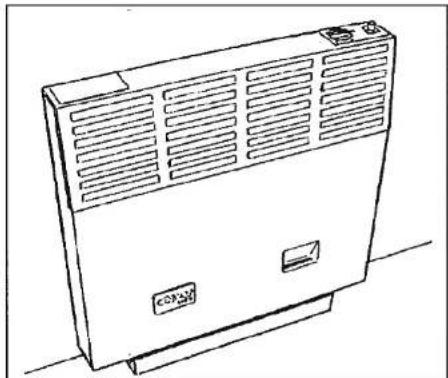
natural_image
Line drawing of a portable air conditioner unit with ventilation grilles and control panel (no text or symbols)CARVER 2000
To light and adjust the heater follow the instructions for 1800 except for 2.4 which in addition reads:
The burner will cycle high/low automatically as required by the built-in thermostat to maintain the temperature.
CARVER 3000
LIGHTING THE HEATER
Follow the procedure for lighting the 1800, then refer to relevant heater detail.
USER'S INSTRUCTIONS
The heater is controlled by a knob mounted on the top of the heater case
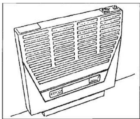
natural_image
Line drawing of a portable air conditioner unit with ventilation grilles and control panel (no text or symbols)which operates a thermostatic gas control valve. Ignition of the Carver 3000 is by a manually operated piezo spark generator and the Carver 3000 Auto is by an electronic reignition system powered by two AA size batteries and operated by a micro switch mounted on the thermostatic gas control.
TO ADJUST THE ROOM TEMPERATURE
Turn the Gas Control Knob to the setting that gives the required comfort level. The main burner will 'cycle' on and off automatically as required by the thermostat to maintain to the set temperature but the pilot flame will always remain alight.
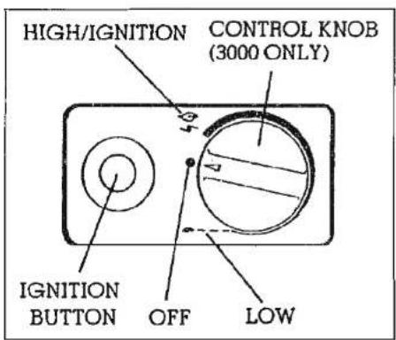
text_image
HIGH/IGNITION CONTROL KNOB (3000 ONLY) IGNITION BUTTON OFF LOWCARVER 3000 AUTO & 5000
1. BEFORE LIGHTING THE HEATER
(a) Ensure that the Gas Supply is turned on and that the batteries have been fitted into the igniter unit.
2. LIGHTING THE HEATER
(a) Turn the Gas Control Knob fully anti-clockwise and then press down.
(b) As the igniter operates a 'ticking' noise may be heard.
All other instructions are as for 1800.
NOTE 1:- The ignition unit fitted to this heater is an automatic relight system so that if the pilot burner flame is
Fitted Equipment
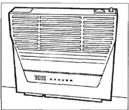
natural_image
Line drawing of a 3000-carvester fan with ventilation grille (no text or symbols on the device itself)extinguished the igniter unit will automatically attempt to relight it. After approximately 20 seconds the flame failure device will operate and close down the gas control to a safe condition. The igniter unit will continue to operate until it is manually turned off. When this occurs check the system and WAIT 3 MINUTES before attempting to relight.
NOTE 2:- To change the batteries ... Locate and remove the battery holder from the ignition unit mounted on the base of the appliance. Discard the old batteries and fit the new ones according to the polarity diagram inside the holder. Refit the holder into the ignition unit.
Fitted Equipment
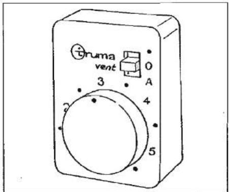
text_image
Truma vent 0 A 3 4 5- Blown Air Fan Control
CENTRAL HEATING
Carver Central Heating provides warmth throughout the caravan by blowing warm air to where it is needed via outlets around the caravan. Please note, not all the components will be fitted to your caravan. When operating the system it is important to balance it. This is achieved by opening the outlets furthest away from the heater more than those nearest to it. The precise arrangement will vary from caravan to caravan and the optimum system will be achieved through experience.
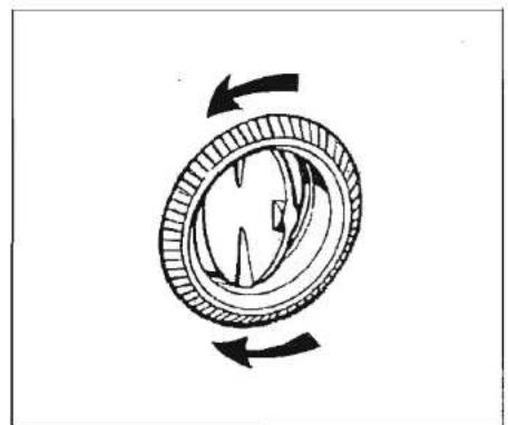
natural_image
Diagram of a mechanical component with rotational arrows indicating motion (no text or symbols)- Butterfly Outlet
BLOWN AIR FAN
"●" gives manual fan speed control for cold air circulation. The fan speed is regulated by the knob. "O" is OFF. "A" is automatic speed control.
The fan speed is high when the heater is on maximum output and is progressively reduced as the heater thermostat reduces the heat output.
The maximum speed is controlled by the knob.
BUTTERFLY OUTLETS
The Butterfly plate may be opened or closed to control the quantity of air and may also be twisted around to control direction. For uniform distribution outlets nearest the heater should be closed more than those further away.
Fitted Equipment
THETFORD CASSETTE PORTA POTTI TOILET
Introduction
The new Thetford Cassette Porta Potti design is functional and incorporates modern sculpture styling with home-like features making it aesthetically compatible with the Caravan bathroom decor. The unit is an integral part of the Caravan bathroom.
The Cassette Porta Potti is constructed of high quality plastics for durability and has a high gloss finish that is easy to clean and maintain. The unit consists of two sections, a permanently installed toilet system and a slide out waste holding tank - CASSETTE.
The toilet section includes a seat and cover, flush and valve blade opener knob, toilet tissue compartment and holder, waste level indicator, built-in toilet fluid storage compartment, a drip tray - a drain tube assembly also level indicator for fresh water tank and a fresh water tank.
The unique Cassette section is located underneath the toilet and is removed for emptying from outside the caravan through an access door. A rotating pour-out spout, automatic holding tank vent, air release valve, valve blade, carrying handles and hand grips are incorporated into the Cassette.
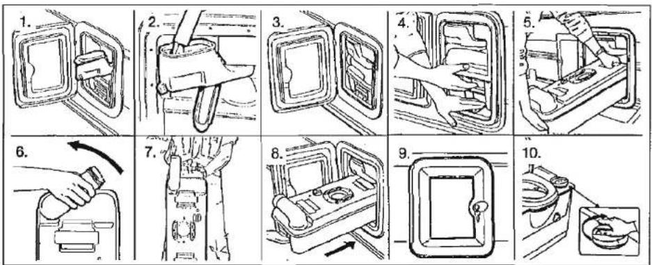
Other features include a safety sensor switch that guards against adding water to the bowl without Cassette in proper position. The Thetford Cassette Porta Potti is a unique solution to a caravan's sanitary problem.
Preparing for use
- Open access door on the side of the caravan and swing out fresh water fill funnel.
- Fill freshwater tank using a hose or jerrycan until water funnel level reaches neck. A 12v electric socket is located on the outside of the caravan (excluding Rapide models) near to the access door. This is for use with the Whale
submersible pump, which is available as an additional accessory, to fill the freshwater tank of the cassette toilet. (The pump is supplied as standard on Corniche and Conqueror models.) Tank capacity is 15 litres. During use the drain tube works as a level indicator for the fresh water tank. Aqua Rinse may be added to improve cleaning of bowl and flushing of unit.
- Replace cap. Swing water fill funnel inward until it touches side of water tank. Note: 150ml of water will remain in fill bottle when fresh water tank is empty.
- Next add Aqua Kem to Cassette for controlling odours. Depress retaining clip.
Fitted Equipment
- Remove cassette by pulling straight out. When Cassette hits stop, tilt downward slightly and remove (stop for safety when Cassette is full).
- Position tank vertical and swivel pour out spout upward.
- Remove cap. Remove deodorant from storage compartment. Add 100ml of Aqua Kem or 120ml of Aqua Kem Bio through pour out spout. Add small amount of water through spout to cover tank bottom. Replace cap and return pour out spout to its original stored position.
Note: As an alternative deodorant can be added to Cassette through the valve blade opening.
Hotter weather or longer retention time may require addition of more Aqua Kem.
CAUTION: Do not add Aqua Kem Concentrate or Aqua Kem Bio directly into toilet bowl while Cassette tank valve blade is closed. Pressure due to heat and altitude change can build up in the Cassette tank causing bowl contents to splash upward upon opening the valve blade, if opened too fast. Before each use, open and shut the Cassette valve blade to vent the tank.
- Slide the Cassette, pour out spout facing outside into the caravan
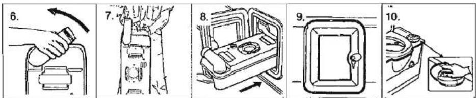
through access door. Never force insertion or removal of the Cassette tank, damage to system can occur.
- Make sure the Cassette is secured by the retaining clip. Close and lock access door.
OPERATION
Flushing
- Before using the toilet we advise to add some water to the bowl by pressing down the flush knob. This avoids marking the bowl. Water will stop flowing when knob is released.
- To flush after use, turn the flush knob in an anti-clockwise direction and pump it repeatedly. The turning motion opens the valve blade, emptying the toilet bowl. This procedure results in the best bowl rinse and most efficient use of water. After flushing, turn the knob in a clockwise direction to close valve blade. The toilet can also be used with
the valve blade open, which allows the waste to go directly into the holding tank.
Toilet Tissue
- Toilet tissue is stored in the specially designed storage compartment that helps keep tissue clean and dry. Tissue can also be suspended on a tissue holder using the special wall mount bracket, if desired.
- To replace tissue, remove tissue holder from compartment by pulling up on tissue cover. Hold bottom of tissue holder in one hand and cover in the other, and turn in opposite directions until you hear a click. Pull apart. Place tissue on holder, insert prongs of cover into holder. Hold cover and holder and twist in opposite direction until locked. Aqua Soft toilet tissue is recommended for best results.

text_image
Fitted EquipmentEmptying the Cassette
The Cassette capacity is 20 litres and should be emptied when the waste level guage indicator goes from green to full red. The gauge does not begin to move from green to red until the tank is over half full.
Caution: Do not allow Cassette to become overfilled, see Trouble Shooting section for emergency emptying procedure.
To empty Cassette be sure that the valve blade is in the closed position.
- Open the access door on side of caravan. Depress the retainer clip, pull Cassette until stop, tilt and remove Cassette.
- Carry the Cassette using the lower carrying handle, pour out spout up, to a normal household type toilet or other authorised disposal point. Set Cassette in vertical position on the ground and rotate pour out spout upward.
- Remove spout cap. Grasp unit by upper carrying handle nearest to pour out spout. Place other hand on upper rear grip so that the air relief vavle button can be depressed with thumb while emptying, to ensure smooth outflow of tank contents. When empty, rinse tank and valve blade with water.
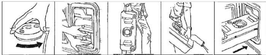
natural_image
Five-step diagram showing a car seatbelt mechanism with hand positioning and tool insertion (no text or symbols)Note: Depress air release valve button only when pour out spout is pointed downwards.
- After preparing for use, slide the Cassette into the caravan. Check to make sure that the retaining clip secures the tank in a locked position. The pour out spout end of the tank should be visible through the access door opening. Add water to the fresh water tank as outlined in "Preparing for Use" section. Close and lock access door.
CLEANING AND MAINTENANCE
No routine maintenance is required on the Thetford Cassette Porta Potti. The use of Aqua Rinse helps to clean and protect the toilet bowl, valve blade and seals during flushing. Do not use strong household detergents or cleaners with chlorine, solvents or acid contents, as they will damage valve seals.
Empty Cassette and rinse tank with clear
water. Use a mild soap to clean toilet bowl, seat and cover, as well as exterior of toilet unit and Cassette. Replace tank inside caravan.
Note: Pour-out spout and vent plug can be removed. Seals should be greased if necessary with acid-free vaseline.
WINTERING/STORAGE
The Thetford Cassette Porta Potti is easily winterised for storage or cold weather use.
- Empty the fresh water tank using the drain tube/fresh water tank level indicator. Pull level indicator/drain tube down from top plug position outward through door opening to drain water from tank.
19 Empty the water fill funnel by pulling the bottle away from tank. Remove small water cap at fill bottom, allowing water to drain from water funnel.
Note: Do not tighten caps, this helps in keeping unit dry.
Fitted Equipment
Cold Weather Use
To prevent freezing during cold weather use, add anti freeze to the fresh water tank. Use a non-toxic (propylen-glycol) type of anti freeze. Refer to chart on container to obtain level of protection.
High Altitude and Hot Weather Use
With large temperature differences and changing heights during driving, overpressure can start to build up in the holding tank. To depressurise your tank continuously, we recommend to keep the flush knob about 10 degrees in the direction of the arrow.
THETFORD WARRANTY
- The Thetford Cassette Porta Potti is warranted to the original buyer for one year from the date of purchase, provided the warranty card duly completed has been returned to us within 30 days after the date of purchase.
- The warranty covers replacement of parts arising from defects and workmanship and from the inability of the unit to perform its intended function.
- In case of a defect apply to original dealer with proof of purchase.
-
Defects, which in our judgement occurred from misuse, negligence or accident, are not covered by the warranty. In addition, the warranty does not apply if the product is installed or handled improperly or if other than the prescribed chemical agents have been used or if the product has been altered in any way or has been repaired by unqualified persons, or if the serial number and/or date has been altered or removed.
-
Should the original buyer wish to return to us parts believed to be defective, the parts should be sent prepaid. If we find the parts defective and covered by warranty, they will be repaired and returned. If warranty does not apply or has expired, a nominal charge will be made. Any transport costs are for the account of the owner.
- Before returning product or parts they should be cleaned, in order to carry out inspection and repair.
- No other warranty is given and no personal representative is authorised to make any warranty or assume liability by words or action under any warranty other than that is contained herein. This warranty is expressly in lieu of any other expressed or implied warranty of whatever nature and expressly excludes any other or further liability.

text_image
Scanned document page with dense text, tables, and a watermark at the bottom right corner.Fitted Equipment
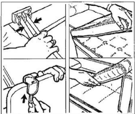
natural_image
Four-panel illustration showing hands using a tool to adjust a key, with no visible text or symbols.Bedding
Sleeping bags and continental quilts can be compressed into small spaces and can be ready to use in minutes.
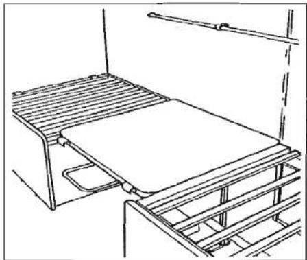
natural_image
Line drawing of a simple indoor space setup with a bed, metal frame, and ladder (no text or symbols)Lower Single Beds Assembly
- Retract two locating clips under table top nearest the wall.
- Life edge of table nearest wall.
- Manoeuvre table into convenient position.
- Grasp table leg 3 to 4 inches from underside and squeeze the two sections together, allowing the leg to fold parallel with the underside.
- Remove seat cushions, rotate table top through 180° and locate in recess on both seats.
- Arrange seat cushions as appropriate.
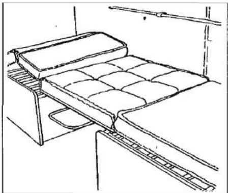
natural_image
Line drawing of a bed rack with a tray and seat arrangement (no text or symbols)Note: It is recommended to place some absorbent material, i.e. a towel or tissue paper underneath the cushion above the table to reduce the possibility of moisture or condensation building up.
Fitted Equipment
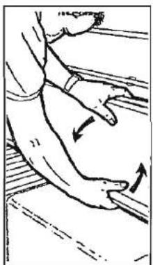
natural_image
Line drawing of a hand pressing down on a wooden surface, showing motion direction (no text or symbols)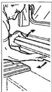
natural_image
Diagram of a mechanical or structural assembly with arrows indicating motion direction (no text or symbols)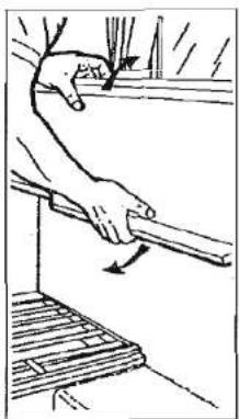
natural_image
Illustration of a hand using a tool to lift or lift a wooden plank (no text or symbols)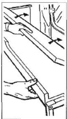
natural_image
Illustration of hands using a tool to adjust or install a mechanical component (no text or symbols visible)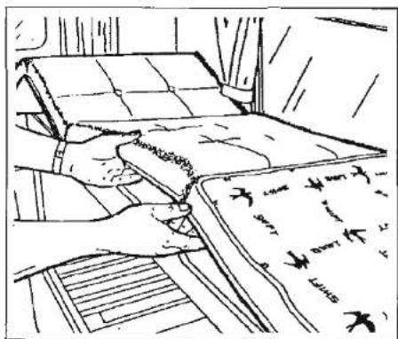
natural_image
Line drawing of a person using a tool to clean or inspect a document on a surface (no text or symbols visible)Bunks (Side)
- Grasp bunk as shown and pull.
- The bunk is designed to automatically move into the correct position.
- Unfold and secure.
- Arrange seat cushions appropriately.
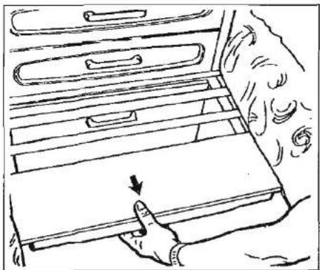
natural_image
Line drawing of a hand inserting a drawer into a rack, with an arrow indicating the direction (no text or symbols present)Double Bed Assembly
- Grip front of slatted bed and walk backwards until bed is fully extended.
- Arrange seat cushions.

natural_image
Grayscale abstract texture with no discernible text, symbols, or structured elementsFitted Equipment
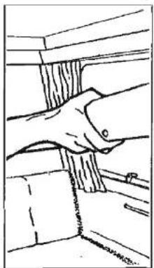
natural_image
Line drawing of a hand gripping a wall, no text or symbols present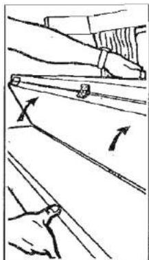
natural_image
Diagram showing two hands holding a tool with directional arrows indicating movement or force (no text or symbols present)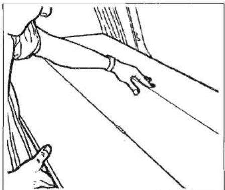
natural_image
Line drawing of a person's arm reaching toward a window, with no text or symbols present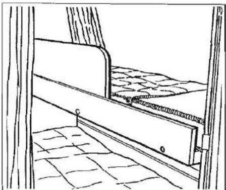
natural_image
Line drawing of a wooden door with a textured floor and a wall, no text or symbols presentBunks (Rear)
The bunks (if any) fitted to your caravan are guaranteed to a weight limit of 11 stones (70 kg).
An optional safety web can be supplied to prevent the occupant from falling out of the top bunk.
- Remove bunk from its stored position below lockers, taking care to draw out each side equally thus avoiding damage to the caravan walls.
- Locate on bunk supports and unfold, ensure open bunk is pressed firmly into position and cannot slide out of bunk supports.
- Locate safety board.
- Arrange seat cushions to suit.
On caravans with rear side windows fitted with cassette blinds, care must be taken to avoid damaging the blind frame. Lower the bunk bed (unopened) onto the rearmost section of the bunk support rails, slide the front of the bunk forward whilst at the same time unfolding it.
Ensure that your fingers are clear of the front upstand whilst opening and closing the bunk.
Fitted Equipment
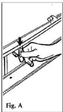
natural_image
Illustration of a hand using a tool to measure a mechanical component, labeled Fig. A (no text or symbols on the diagram itself)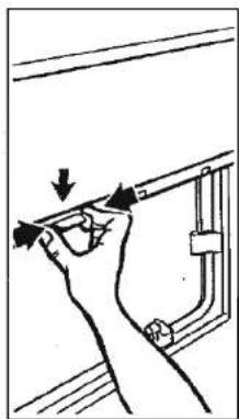
natural_image
Hand holding a tool near a wall-mounted pipe or duct (no text or symbols visible)CASSETTE BLINDS (Fig. A) (Fitted to rear bunk, side windows)
The blind and flyscreen cassettes fitted to your caravan are easily removed by releasing the screws around the beige frame. The unit will come away from the wall in one complete assembly for easy maintenance and replacement of parts.
The blinds should remain reliable as long as they are treated with care. The following list do's and don'ts will help keep your blinds smooth-running and trouble-free.
- When separating the blind from the flyscreen, ALWAYS control them by hand. DO NOT let them spring back freely.
- Always pull a blind down by its centre catch. DO NOT pull down by one side of the blind, as this will cause snagging and uneven running.
The centre mechanism allows for the blind to be locked into three positions.
FLYSCREEN
Pull down using the thumb tag. If two tags are fitted, use both. The flyscreens close in only one position (fully down). Pull down, push towards window and release slowly into retaining slot.
To release, pull downwards and inwards. Hold thumb tag whilst allowing screen to retract.
The rear side windows have a two part blind/flyscreen which can be joined together to operate as a combined unit for maximum adjustment of height and ventilation. When releasing the two parts, the blind section must be located into one of its retaining slots. The flyscreen can then be detached and restrained whilst it is allowed to return to its closed position.
ROOF LIGHTS
When opening the roof lights, care must be taken to release the locking mechanism as the unit is raised.

text_image
Scanned document with dense text, likely a formal letter or official recordFitted Equipment

natural_image
Line drawing of a person using a tool to adjust or install a vehicle chassis panel (no text or symbols present)TABLES
Slide top of drawers out and fold back to form convenient table. (Fig. A)
The pedestal table can be swung round for easy access to the seating and then re-positioned afterwards. (Fig. B)
The free standing table legs have a positive locking mechanism. Care must be taken to ensure that, when folded, the leg which is closed first locks into the second position. When engaging legs in down position the mechanism must be positively locked down. (Fig. C)
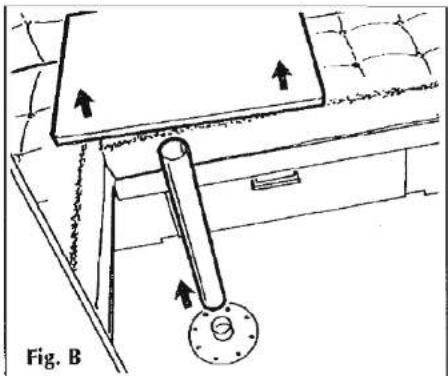
natural_image
Technical line drawing of a mechanical assembly with directional arrows indicating motion (no text or symbols)Note: Tables should NOT be stored in the toilet compartment whilst in transit. It is recommended that they be placed between the front beds. (Rapide and Cappuccino only)
Tables stored in the table storage compartment must be securely clipped into place whilst in transit.
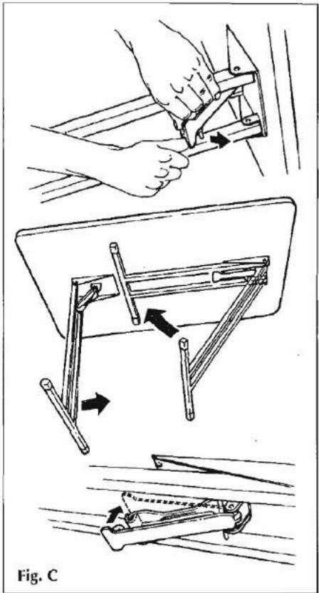
natural_image
Illustration of a manual folding or cutting process using a tool, showing steps from opening to cutting (no text or symbols present)Fitted Equipment
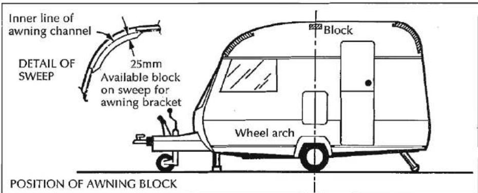
text_image
Inner line of awning channel DETAIL OF SWEEP 25mm Available block on sweep for awning bracket Block Wheel arch POSITION OF AWNING BLOCKAWNING POINTS
Provision is made for fixing awning brackets to your caravan.
The centre fixing points are determined from the centre of the wheel arch and just below the awning rail.
The end fixing points are indicated in the illustration.
Care must be taken when fixing and it is recommended that Butyl tape (19mm × 2mm IDL303) or Gun applied Mastic (IDL 99) be used between the brackets and the caravan.
ASH FRAMED DOORS
The ash framed toilet compartment doors may be fitted with a tensioning rod to straighten out any warping. Knurled wheels are fitted to the top and bottom of the doors.. These should be used as follows:
A To remove a bow where the top and bottom of the door have bowed away from the toilet compartment wall - tighten the tension.
B To remove a bow where the middle of the door has bowed away from the toilet compartment wall – slacken the tension.
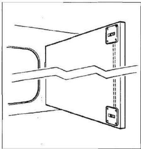
natural_image
Pure technical line drawing of a mechanical component with no text or symbolsWarping of the ash framed doors is most likely to occur when air humidity is high and the tensioning rods should be slackened off during periods of high humidity.
MAINTENANCE
Caravan Exterior 62
Panels 62
Cleaning 62
Mouldings 62
Removing Tar 62
Windows 62
Condensation 62
Caravan Interior 62
Side Walls and Roof Linings 62
Soft Furnishings 62
Work Surfaces 62
Cupboard Catches 62
Vanity Unit 63
Furniture 63
Winter Storage 63
Wheels/Tyres 63
Jacking 63
General 63
Alko Running Gear 64
Operation and Maintenance 64
General Maintenance 68
Brake Hubs and Wheel Bearings 68
Couplings 68
Towing Ball 68
Over-running Device 68
Jockey Wheel 68
Brake Linkage 68
Corner Steadies 68
Braking System 68
SYSPAL Aluminium Chassis 69
ALKO Galvanised Chassis 69
Tyre Wear and Damage 70
Wheels 70
Maintenance
CARAVAN EXTERIOR
Aluminium Panels
The stove enamelled paintwork is very durable and easy to clean owing to the high gloss properties.
Plastic Panels (GRP/ABS)
These are used for front and rear panels and, in some cases, for roof panels.
Cleaning
For both aluminium panels and plastic panels.
- Wash the caravan regularly with mild detergent. Rinse with cold water and leather off.
- For better protection a similar coloured good quality car wax may be applied.
WARNING: Under no circumstances use any abrasive cleaning agents or solvents on the exterior panels.
Mouldings
All mouldings are of anodised aluminium and will retain their lustre for a long period if no abrasive materials are used to clean them.
Removing Tar
Use 'Jove Tar Remover' on our double glazed windows, it is obtainable from most leading car accessory or Do-It-Yourself
shops such as Halfords. Do not use petrol or other chemicals.
Acrylic Windows
The windows in your Swift are fully double glazed and with care will remain sparkling and scratch-free.
Cleaning: Wash down as you would your car. Do not use a sponge on dirty windows (you wouldn't on your car).
When all dirt has been removed, dry with a leather or 'Vyleda' type cloth, the catches and stays do not require lubricating.
Keeping your acrylic windows sparkling:
Small scratches: For small scratches it is possible to use a liquid metal polish such as 'Brasso' or a proprietary acrylic polish of a suitable grade dependent upon the severity of the scratches.
Condensation
As your caravan is double glazed you may occasionally get condensation inside the double glazing. This is particularly so in severe weather change (usually spring and autumn) and is easily cured in dry weather.
i) Remove the plastic plugs from interior top of each window.
ii) Leave unplugged for approximately 1-4 hours until condensation has cleared.
CARAVAN INTERIOR
Follow these guidelines to ensure your investment is receiving the very best attention.
Side Walls, Roof Lining
A simple wipe over with a damp cloth and a very mild detergent is all that is needed.
Soft Furnishings
Should be vacuumed occasionally to remove grit and sand and help to keep its smart appearance and ensure long life. The upholstery can be cleaned with a mild, reputable upholstery cleaner. It is recommended that the curtains are dry cleaned. The foam used in cushions is manufactured to meet fire regulations. It requires time to return to its normal position after prolonged use.
Work Surfaces
You should not stand very hot items on any of the work surfaces, especially models with plastic moulded sinks and drainers.
Cupboard Catches
It is advisable to lightly oil all cupboard catches, sliding bolts and hinges from time to time.
Maintenance
Vanity Unit
Your caravan is fitted with a vanity bowl. Do not pour very hot water into it. Always put the cold water in first. The bowl is retained by a bed of sealer and can easily be removed by lifting. This will give access to all toilet compartment plumbing connections.
Furniture
A simple wipe over with a damp cloth should be all that is required.
Polishing with a proprietary brand of wax polish enhances and maintains furniture in showroom condition.
It must be remembered that because the frames of the doors are made of ash, which is a natural product, they can be affected by temperature and humidity and may bow under certain conditions. As conditions change they should revert to their original positions. (Also see page 60 on Door Tensioner Rod.)
WINTER STORAGE
1. Wheels/Tyres
This applies wherever your caravan is stored particularly during the winter months.
Do not store in one position with partially deflated tyres.
The tyre walls will suffer and do present a real danger of blow-outs, especially when travelling at faster speeds than are allowed in the U.K.
The wheels should be turned every couple of weeks or even better, the wheels removed.
2. Jacking
Follow jacking procedure for changing a wheel.
Lower the caravan onto stout wooden blocks, axle stands or winter wheels.
3. General
All moving parts should be checked for free operation.
Lubrication should be carried out at the points illustrated, on page 69.
It is recommended that the complete coupling and brake drums are covered with a plastic bag, tied at the end to prevent moisture entry.
Charge up on board battery every 2 months.
Sterilize, then drain the water system - freezing weather could result in damaged components. Don't forget the shower head. Leave taps open.
If possible remove upholstery before placing the caravan into winter storage. Alternatively, stand the cushions on their
edges to allow circulation of air. This will reduce the possibility of dampness from condensation.
Keep curtains closed, to minimise fading of furniture.
Leave doors and lockers open to allow air to circulate fully.
Leave refrigerator door open.
Before starting caravanning after a long lay-off check all gas appliances, points and electrics.
Note: Preferably not less than once a year, the electrical installation should be inspected and tested by a qualified electrician.
THIS IS PROBABLY AN OPPORTUNE MOMENT TO ARRANGE FOR THE CARAVAN TO HAVE ITS ANNUAL SERVICE AT YOUR SWIFT APPOINTED DEALER.
Other useful tips
-
Do not park near trees or larch lap tyre fences, due to possible wind damage.
-
Keep any grass around the floor of the caravan short, to maintain air flow and stop any possible damp getting into the caravan.
IMPORTANT: Always follow manufacturers' recommended procedures after use of fitted equipment in the caravan and before storing for any length of time.
Maintenance
ALKO RUNNING GEAR
Coupling Head
The ball couplings are entirely automatic in operation and designed for one hand operation to suit the 50mm international ball recommended by the British Standards Institution, National Caravan Council and the Society of Motor Manufacturers and Traders. Each type has provision for an anti-theft device (available as an extra) consisting of brass insert, complete with 2 keys. The locked button will prevent movement of the handle, therefore making it possible to lock the coupling either "on" or "off" the towing ball.
Operation:- Type AK10/2
Lift locking trigger, and lift handle upward and forward. Place the unlocked coupling onto the towing ball and with the slightest downward pressure it will lock onto the ball automatically. Ensure locking trigger returns to its free position before commencing to tow.
Operation:- Type AK 13/2
Lift handle upward and forward, this disengages the security tooth. Place the unlocked coupling onto the towing ball and with the slightest downward pressure it will lock onto the ball automatically. The security tooth should again be fully engaged.
Uncoupling
Having lowered the jockey wheel to the ground, operate the handle as previously described. Lift the coupling clear of the towing ball either manually or by operating the telescopic jockey wheel.
IMPORTANT
If the nose of the caravan is lifted manually the locking trigger must be engaged first and the handle lifted forward. Failure to do this will cause the nose-weight to be transmitted through the locking button and damage will occur.
Forward Braking
In the free position, with the handbrake fully forward in the OFF position, the drawshaft of the overrun device is fully extended and the shoes are clear of the drum.
As the towing vehicle brakes, or starts to drive downhill, the drawshaft of the overrun device is depressed toward the unit being towed. This action imparts linear motion to the main shaft of the overrunning device which is transmitted via the overrun lever, brake rod and Bowden cable to the expanding clutch. This mechanism forces the leading brake shoe and, by reaction, the trailing shoe outwards into contact with the drum. Friction between the brake shoes and the drum creates a tendency for both shoes and the expanding clutch to move in the direction of forward rotation until they abut against the adjuster box. This ensures that both remain in the braking position.
Reversing
When the towing vehicle reverses, the drawshaft is pushed backward, moving the overruning device through its full travel. This movement is transmitted in the normal manner to the expanding clutch.
The clutch forces both shoes into contact with the drum. Initial friction between these creates a tendency for the shoes and expanding clutch to move in the direction of wheel rotation i.e. reverse. This movement imparts pressure to the spring-loaded auto-reverse lever, causing it to collapse. Thus, friction between the shoes and drum is almost eliminated, allowing the trailer to reverse in concert with the towing unit.
Slight forward movement of the chassis will allow the coil spring to reassert itself, enabling the reverse lever to recover to its normal position. Normal braking is then immediately available.
Maintenance
Parking
The AL-KO parking brake system incorporates a patented device for added safety when parking on a reverse-sloping site or steep hill.
The AL-KO parking brake system comprises a handbrake lever mechanism actuating a Bowden cable which operates a brake unit assembly contained within the wheel hub.
AL-KO provide two types of parking brake system on their trailers, with the Bowden cable and the wheel hub brake unit being common to both types.
The difference between the systems is the handbrake mechanism used to actuate the Bowden cable.
AL-KO's unique parking brake system requires a source of stored energy to lock the wheel brakes should the trailer start to move after it has been uncoupled from the towing unit.
This energy source can be provided by either a spring cylinder charged by hand or by a gas filled cylinder acting as an energy store.
Each system requires a slightly different method of operation when parking the trailer, though they both operate in the same manner when forward or reverse braking is applied.
Spring Cylinder Type
A spring system is attached to the link between the handbrake lever and the central brake rod. Full application of the handbrake lever (such that the lever is vertical) to the last tooth of the ratchet compresses a steel spring inside the steel cylinder and energy is stored.
The action of the brake lever imparts motion to the brake rod, the Bowden cable and the expanding clutch. This mechanism forces both shoes into contact with the drum.
At this stage, the brake unit is latent, the mechanism waiting to see in which direction the trailer will start to move.
If the trailer starts to move backwards, the stored energy in the spring will be released. The trailing brake shoe and by reaction, the leading shoe together with the expanding clutch will tend to move in the direction of rotation (reverse) and abut against the stop. Thus the trailer is braked.
However, if the handbrake is NOT fully applied to the last tooth (i.e. vertical) and is set to some lesser position than the full vertical, then problems will almost certainly arise after the trailer has been uncoupled from the towing unit.
If the trailer is parked on a reverse slope or if it is pushed backwards, then the brake
mechanism will act as though the trailer is being reversed by the towing unit. The shoes and expanding clutch will tend to move with the direction of rotation (reverse) which imparts pressure to the spring-loaded reverse lever, causing it to collapse. Thus, friction between the shoes and the drum is almost eliminated and the trailer will run away.
Operating the Handbrake
Some people may find it difficult to set the handbrake lever to its full vertical position without a great deal of physical effort.
However, AI-KO have designed their system so that the average user need not do so.
For successful parking on a reverse slope or steep hill, the operator need only apply the handbrake with one hand while gently but purposefully inching the caravan trailer a small distance backwards with the other.
The user must supply this small but essential backward movement to ensure that the fulcrum of the transmission lever moves past the point of reverse, thus preventing the lever from collapsing as it would normally do when reversing.
Most users will find it easier to stand facing the towing unit while applying the handbrake and at the same time gently push the caravan an inch or two backwards with their posterior.
Maintenance
Gas Cylinder Type
A gas cylinder, acting as an accumulator of stored energy, can be fitted to the handbrake lever to provide the same effect as a spring cylinder.
This system is much more user friendly, as the handbrake lever need only be applied until it passes a clearly detectable dead point for it to render parking on reverse slopes or steep hills absolutely safe.
It takes minimal effort from the operator to move the handbrake lever past this dead point.
If the caravan or trailer starts to move when uncoupled from the towing unit, then the energy stored in the cylinder is released and the brakes applied in the normal manner.
Important Points to Remember
It is absolutely vital that the slight backwards push of the caravan or trailer is applied before it is uncoupled from the towing unit.
It is also important to check that the brake has in fact operated correctly as soon as the caravan has been uncoupled.
If the caravan or trailer is to be parked on a steep slope or on loose or slippery surfaces, it is advisable to chock the wheels.
Where possible, always ensure that the handbrake lever is in the fully vertical position.
When the handbrake has been applied, it is possible for the caravan or trailer to roll back as much as 25cm before the full force of the brake takes effect.
All components of both the overrun device and the wheel brakes must be those manufactured by AL-KO as the braking and reversing systems must be matched to ensure optimum braking performance.
Combining parts manufactured by AL-KO with those produced by other suppliers will invalidate any guarantee entered into by AL-KO.
Recommended Brake Adjustment Procedure
Jack up the axle raising the road wheels clear off the ground. Ensure drawshaft is fully extended (in the towing position) and the handbrake is in the "OFF" position (fully forward).
Check that there is some end float in the rod and spring cylinder.
Adjust brakes first (Fig. A) and the linkage only if necessary.
IMPORTANT: During Wheel brake adjustment the drum must only be revolved in the direction of FORWARD rotation. Do not use excessive force during adjustment.
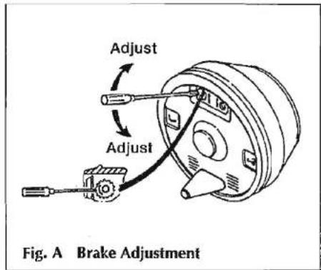
text_image
Adjust Adjust Fig. A Brake AdjustmentWheel brake adjustment is effected through a hole in the brake backplate (see Fig. A). With a screwdriver adjust the starwheel in the direction of the arrow until there is resistance to wheel movement. Slacken until the brake drum turns freely in the forward direction. A check for correct adjustment can be made at the chassis end of the bowden cable. When pulled the cable should extend between 5 and 8mm.
Apply the handbrake two or three times to ensure brake shoes are centralised in the drum. Re-check the shoe clearance at the wheel brake.
Centre brake rod. Check full thread

text_image
Scanned document with faint text and a small embedded image showing partial characters and numbers.Maintenance
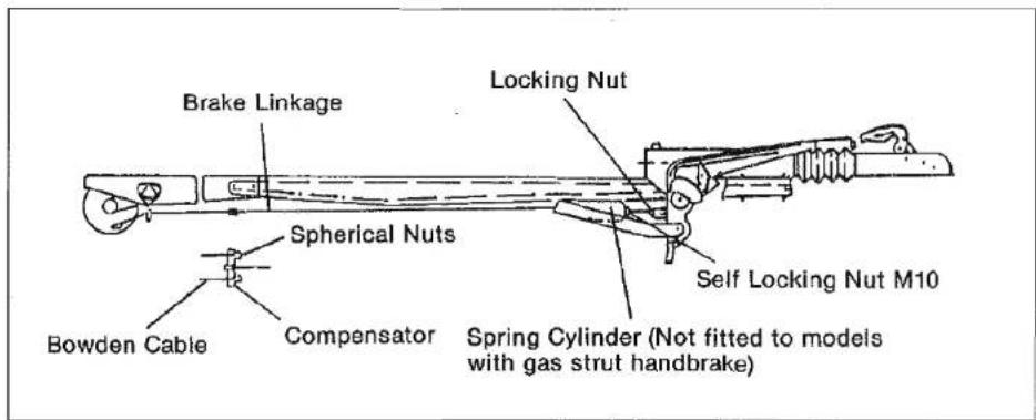
text_image
Brake Linkage Locking Nut Spherical Nuts Bowden Cable Compensator Spring Cylinder (Not fitted to models with gas strut handbrake) Self Locking Nut M10engagement in the fork end of the overrunning device. Secure locking nut.
At the axle ensure compensator plate is parallel to the axle by setting the adjuster nuts on the bowden cables. Secure lock nuts.
Adjust centre brake rod at the rear nut so there is no clearance between the overrun lever and the drawshaft and plate. Secure lock nuts.
Correct adjustment of the linkage can be checked by engaging handbrake lever on the second tooth of the ratchet segment. In this position you should feel a slight braking force at the wheels.
Finally screw up the self locking nut to give 1mm clearance between the nut and the spring cylinder.
Note:- Reversing will be difficult if either wheel brake or brake linkage is overadjusted.
Maintenance
GENERAL NOTES ON MAINTENANCE
1. Brake Drum/Hub Assembly
Removal: Having removed the grease cap, take out the split pin and unscrew the hub nut. The hub/drum can then be removed although a few taps with a mallet may be required. Ensure that handbrake is "off" before attempting to remove.
Lubrication: The wheel bearing hubs are packed with grease on assembly and should be repacked at approximately 6000 miles or biannually. Mobilgrease MP is recommended. NOTE: It is as important not to overpack the hubs with grease as it is not to allow the bearings to run dry.
2. Alko Wheel Bearings
- After 500 miles and thereafter at intervals of 3000 miles or 1 year, the wheel bearings should be checked for side play.
- To remove 'push in' grease cap, tap lightly around the periphery.
- Remove split pin and tighten castle nut (right hand thread) until free rotation of drum is impaired.
- 'Slacken off' for 112 of a turn (30°) until a slot is in line with the cross hole in the stub axle.
- Use a new split pin. Secure the castle nut.
-
Recheck that the rotation of the drum is free.
-
Refit 'push in' grease cap.
3. Couplings
- Clean and grease spherical seat, bearing parts and pivot pins regularly.
- Thoroughly examine all moving parts for wear and correct functioning.
- Couplings should never be drilled.
4. Towing Ball
The automobile towing ball should measure 50mm maximum and 49.5mm minimum (DIN 74058). If the ball is found to be worn it should be replaced immediately.
5. Overrunning Device
The device housing is packed with grease on assembly, but will require periodic maintenance to ensure smooth operation of the braking system.
- Regrease the shaft bearings via the grease nipples provided at 3000 mile intervals, and before storage.
- Ensure correct functioning of all pivot pins and levers and oil regularly.
- Ensure correct functioning of handbrake ratchet and oil regularly.
6. Jockey Wheel
Lubricate wheel and screw thread periodically.
7. Brake Linkage
All moving parts should be lubricated periodically to ensure their satisfactory operation.
It is recommended that all brake linkage threads are liberally smeared with grease for protection and as an aid to future adjustment of the system.
8. Corner Steadies
The screw and pivot pins should be lubricated periodically to ensure their satisfactory operation.
9. Braking System
At 500 miles then every 3000 miles or 1 year check and adjust brake linkage to compensate for any stretch of the bowden cables.
Check and adjust wheel brakes to compensate for wear.
IMPORTANT
When replacing the wheels you should tighten the nuts in rotation diagonally, taking care to tighten them equally. The recommended torque is 65 lb/ft.
CHECK THE WHEEL NUTS BEFORE STARTING EVERY JOURNEY,

natural_image
Grayscale abstract texture with no discernible text, symbols, or structured elementsMaintenance
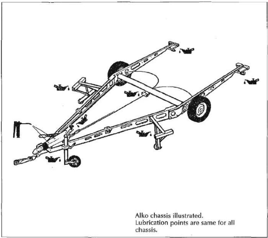
text_image
Alko chassis illustrated. Lubrication points are same for all chassis.THE SYSPAL ALUMINIUM CHASSIS
Aluminium has a high resistance to corrosion, due to the presence on the surface of a thin layer of natural oxide film, which has remarkably good self-healing properties.
In a great many environments, if dissimilar metals are placed in contact, one metal may corrode preferentially. This phenomenon is true of any pair of metals, but it can be prevented by the simple expedient of separating the two metals with a non metallic insulator which may take several forms, including certain paints. It is our suggestion that should the customer require to fit an anti-snake device at a later date he should insulate the bracket from the 'A' frame.
ALKO GALVANISED CHASSIS
Hot dip galvanising offers high corrosion protection by forming a barrier layer through reaction with the atmosphere. This will be apparent by the chassis members changing to a light grey colour. During winter periods or storage where there is insufficient air circulation or heavy moisture, a soft porous, light grey oxidisation layer may form. This is known as 'White Rust' and should NOT be confused with rust. As applied to steel
Maintenance
these deposits should be removed by use of a wire or hard nylon brush.
Note: The chassis fitted to your caravan is shown in the Fitted Equipment List (p. 88).
TYRE WEAR AND DAMAGE
The legal requirement for tread depth on motor vehicles also apply to caravans, i.e. 1.6mm.
In order to equalise wear it is suggested that the wheels be balanced and changed around from time to time.
It is dangerous to neglect tyre damage and should you detect a blister, a rupture or a cut which exposes the casing or if it has suffered a violent impact (for example against a kerb) such that there is a risk of internal damage, it is advisable to have it examined by a tyre specialist as soon as possible.
Tyres should be inspected regularly and if any signs of visible deterioration (sidewall cracking, delamination of tread, etc) are evident, they should be replaced regardless of there being a legal minimum tread depth.
WHEELS
The condition of the wheels should be checked regularly, particularly for distortion of flanges and the wheel dish. Wheels which are damaged or distorted, or having wheel stud seatings cracked or deformed, must not be repaired.
GENERAL DATA
Wiring Diagrams 72
Fault Finding 79
Specifications 82
Equipment Lists 87
Swift Owners' Club 89
Spares and After Sales 89
Accident Repairs 89
Index 91
Guarantee 92
Wiring Diagram

natural_image
Pure horizontal line pattern without any text, numbers, or symbolsRAPIDE (Interior)
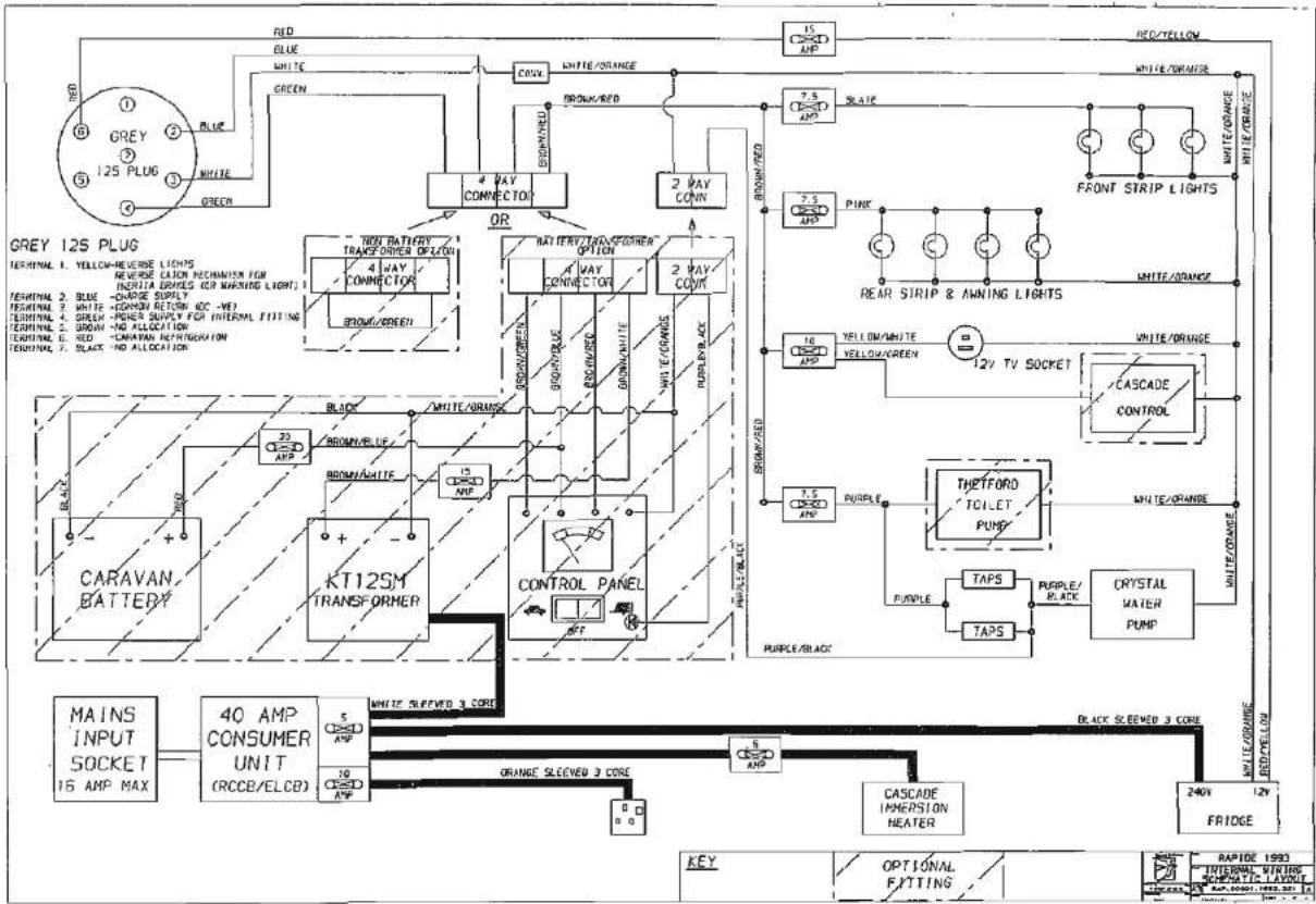
flowchart
graph TD
    A[" Grey 125 PLUG "] -->|RED| B[" Blue "]
    A -->|GREEN| C[" Green "]
    A -->|OR| D[" Black/Purple/Red"]
    A -->|OR| E[" White/Orange/Blue"]
    A --> F[" White/Orange/White"]
    A --> G[" White/Orange/Black/Red/Blue/White/Blue/Black/White/Black/White/Black/White/Black/White/Black/Black/White/Black/Black/Black/Black/Black/Black/Black/Black/Black/Black/Black/Black/Black/Black/Black/Black/Black/Black/Black/Black/Black/Black/Black/Black/Black/Black/Black/Black/Black/Black/Black/Black/Black/Black/Black/Black/Black/Black/Black/Black/Black/Black/Black/Black/Black/Black/Black/Black/Black/Black/ Black Black Black Black Black Black Black Black Black Black Black Black Black Black Black Black Black Black Black Black Black Black Black Black Black Black Black Black Black Black Black Black Black Black Black Black Black Black Black Black Black Black Black Black Black Black Black Black Black Black Black Black Black Black Black Black Black Black Black Black Black Black Black Black Black Black Black Black Black Black Black Black Black Black Black Black Black Black Black Black Black Black Black Black Black Black Black Black Black Black Black Black Black Black Black Black Black Black Black Black<nl>    subgraph Color<br>        direction TB<br>        A1[ GREEN"] --> A2[" GREEN"]
        A3[" GREEN"] --> A4[" GREEN"]
        A5[" GREEN"] --> A6[" GREEN"]
        A7[" GREEN"] --> A8[" GREEN"]
        A9[" GREEN"] --> A10[" GREEN"]
        A11[" GREEN"] --> A12[" GREEN"]
        A13[" GREEN"] --> A14[" GREEN"]
        A15[" GREEN"] --> A16[" GREEN"]
        A17[" GREEN"] --> A18[" GREEN"]
        A19[" GREEN"] --> A20[" GREEN"]
        A21[" GREEN"] --> A22[" GREEN"]
        A23[" GREEN"] --> A24[" GREEN"]
        A25[" GREEN"] --> A26[" GREEN"]
        A27[" GREEN"] --> A28[" GREEN"]
        A29[" GREEN"] --> A30[" GREEN"]
        A31[" GREEN"] --> A32[" GREEN"]
        A33[" GREEN"] --> A34[" GREEN"]
        A35[" GREEN"] --> A36[" GREEN"]
        A37[" GREEN"] --> A38[" GREEN"]
        A39[" GREEN"] --> A40[" GREEN"]
        A41[" GREEN"] --> A42[" GREEN"]
        A43[" GREEN"] --> A44[" GREEN"]
        A45[" GREEN"] --> A46[" GREEN"]
        A47[" GREEN"] --> A48[" GREEN"]
        A49[" GREEN"] --> A50[" GREEN"]
        A51[" GREEN"] --> A52[" GREEN"]
        A53[" GREEN"] --> A54[" GREEN"]
        A55[" GREEN"] --> A56[" GREEN"]
        A57[" GREEN"] --> A58[" GREEN"]
        A59[" GREEN"] --> A60[" GREEN"]
        A61[" GREEN"] --> A62[" GREEN"]
        A63[" GREEN"] --> A64[" GREEN"]
        A65[" GREEN"] --> A66[" GREEN"]
        A67[" GREEN"] --> A68[" GREEN"]
        A69[" GREEN"] --> A70[" GREEN"]
        A71[" GREEN"] --> A72[" GREEN"]
        A73[" GREEN"] --> A74[" GREEN"]
        A75[" GREEN"] --> A76[" GREEN"]
        A77[" GREEN"] --> A78[" GREEN"]
        A79[" GREEN"] --> A80[" GREEN"]
        A81[" GREEN"] --> A82[" GREEN"]
        A83[" GREEN"] --> A84[" GREEN"]
        A85[" GREEN"] --> A86[" GREEN"]
        A87[" GREEN"] --> A88[" GREEN"]
        A89[" GREEN"] --> A90[" GREEN"]
        A91[" GREEN"] --> A92[" GREEN"]
        A93[" GREEN"] --> A94[" GREEN"]
        A95[" GREEN"] --> A96[" GREEN"]
        A97[" GREEN"] --> A98[" GREEN"]
        A99[" GREEN"] --> A100[" Green / Green / Blue / White / Orange / Blue / White / Orange / Blue / White / Orange / Blue / White / Orange / Blue / White / Orange / Blue / White / Orange / Blue / White / Orange / Blue / White / Orange / Blue / White / Orange / Blue / White / Orange / Blue / White / Orange / Blue / White / Orange / Blue / White / Orange / Blue / White / Orange / Blue / White / Orange / Blue / White / Orange / Blue / White / Orange / Blue / Red/Yellow<br>    end<br>    subgraph Power Supply<br>        direction TB<br>        B1[Brown/Brown"] --> B2["Brown/Brown"]
        B3["Brown/Brown"] --> B4["Brown/Brown"]
        B5["Brown/Brown"] --> B6["Brown/Brown"]
        B7["Brown/Brown"] --> B8["Brown/Brown"]
        B9["Brown/Brown"] --> B10["Brown/Brown"]
        B11["Brown/Brown"] --> B12["Brown/Brown"]
        B13["Brown/Brown"] --> B14["Brown/Brown"]
        B15["Brown/Brown"] --> B16["Brown/Brown"]
        B17["Brown/Brown"] --> B18["Brown/Brown"]
        B19["Brown/Brown"] --> B20["Brown/Brown"]
        B21["Brown/Brown"] --> B22["Brown/Brown"]
        B23["Brown/Brown"] --> B24["Brown/Brown"]
        B25["Brown/Brown"] --> B26["Brown/Brown"]
        B27["Brown/Brown"] --> B28["Brown/Brown"]
        B29["Brown/Brown"] --> B30["Brown/Brown"]
        B31["Brown/Brown"] --> B32["Brown/Brown"]
        B33["Brown/Brown"] --> B34["Brown/Brown"]
        B35["Brown/Brown"] --> B36["Brown/Brown"]
        B37["Brown/Brown"] --> B38["Brown/Brown"]
        B39["Brown/Brown"] --> B40["Brown/Brown"]
    end
    subgraph Control Panel
        direction TB
        C1["COUNT R/COUNT R/COUNT R/COUNT R/COUNT R/COUNT R/COUNT R/COUNT R/COUNT R/COUNT R/COUNT R/COUNT R/COUNT R/COUNT R/COUNT R/COUNT R/COUNT R/COUNT R/COUNT R/COUNT R/COUNT R/COUNT R/COUNT R/COUNT R/COUNT R/COUNT R/COUNT R/COUNT R/COUNT R/COUNT R/COUNT R/COUNT R/COUNT R/COUNT R/Count R/COUNT R/COUNT R/COUNT R/COUNT R/COUNT R/COUNT R/COUNT R/COUNT R/COUNT R/COUNT R/COUNT R/COUNT R/COUNT R/COUNT R/COUNT R/COUNT R/COUNT R/COUNT R/COUNT R/COUNT R/COUNT R/COUNT R/COUNT R/COUNT R/COUNT R/COUNT R/COUNT R/COUNT R/COUNT R/COUNT R/COUNT R/COUNT R/COUNT SIREWED 3 CORE<br>    end<br>    subgraph Control Panel<br>        direction TB<br>        C2[COUNT SIREWED 3 CORE<br>      |   |<br>    end<br>    subgraph Power Supply<br>        direction TB<br>        D1[COUNT AMP MAX"] --> D2["COUNT AMP MAX"]
    end
    subgraph Control Panel
        direction TB
        E1["COUNT AMP MAX"] --> E2["COUNT AMP MAX"]
    end
    subgraph Power Supply
        direction TB
        F1["COUNT AMP MAX"] --> F2["COUNT AMP MAX"]
    end
    subgraph Control Panel
        direction TB
        G1["COUNT AMP MAX"] --> G2["COUNT AMP MAX"]
    end
    subgraph Power Supply
        direction TB
        H1["COUNT AMP MAX"] --> H2["COUNT AMP MAX"]
    end
    subgraph Control Panel
        direction TB
        I1["COUNT AMP MAX"] --> I2["COUNT AMP MAX"]
    end
    subgraph Power Supply
        direction TB
        J1["COUNT AMP MAX"] --> J2["COUNT AMP MAX"]
    end
    subgraph Control Panel
        direction TB
        K1["COUNT AMP MAX"] --> K2["COUNT AMP MAX"]
    end
    subgraph Power Supply
        direction TB
        L1["COUNT AMP MAX"] --> L2["COUNT AMP MAX"]
    end
SWIFT/CHALLENGER (Interior)
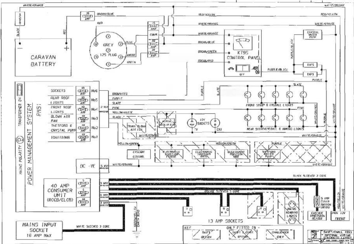
text_image
WHITE/ORANGE CARAVAN BATTERY GREEN/BLUE RED 15 AMPS CONV 30 AMPS 20 AMPS WHITE/ORANGE WHITE/ORANGE GREEN/GREEN GREEN/PSD KT9S CONTROL PANEL QTY PULSE/BLUCK CRYSTAL WATER PUMP TAP5 TAP5 PULPLE WHITE/ORANGE TRANSFORMER ON POWER MANAGEMENT SYSTEM PNS1 SOCKETS 10 CE-E-100000000000000000000000000000000000000000000000000000000000000000000000000000000000000 HEAD ROOF LIGHTS 10 CE-E-10000000000000000000000000000000000000000000000 FRONT ROOF LIGHTS 10 CE-E-1000000000000000000000000000000000000 BLOWN AIR FAN 15 AMPS No4 No3 No2 No1 POKETTS 18 CE-E-15555555555555555555555555555555555555555555555555555555555555555555555555555555555555555 SOCKETS 18 CE-E-16666666666666666666666666666666666666666666666666666666666666666666666666666666666666666666666666666 HEAD ROOF LIGHTS 18 CE-E-171111111111111111111111111111111111111111111111111111111111111111111111111111111111111111111111111111 FRONT ROOF LIGHTS 18 CE-E-24444444444444444444444444444444444444444444444444444444444444444444444444444444444444444444444444444 BLOWN AIR FAN 18 CE-E-2777777777777777777777777777777777777777777777777777777777777777777777777777777777777777777 THEFORD & CRYSTAL PUMP SOCKETS NO.6 No.5 No.3 No.2 No.1 POKETTS 2 VOUTLE GROUND PUNK F. SLATE PINK YELLOW/WHITE BLACK CABBAGE BLOND, AIR FAN. WHITE/ORANGE YELLOW/GREEN ELECTRONIC SWITCHER PLUGGE. ELECTRONIC SWITCHER OVERT. ELECTRONIC SWITCHER REDR. EXXI REACH/ORANGE WHITE/ORANGE YELLOW/GREEN ELECTRONIC SWITCHER PLUGGE. ELECTRONIC SWITCHER OVERT. ELECTRONIC SWITCHER REDR. EXXI WHITE/ORANGE CASSARE CONTROL BLACK SLEEVED 3 CORE WHITE SLEEVED 3 CORE Black SLEEVED 3 CORE MAIN S INPUT SOCKET 16 AMP MAX WHITE SLEEVED 3 CORE KEY SHIFT OPTION ONLY FITTED IN SWIFT 3CrM Option CHALLENGER ONLYWiring Diagram
CORNICHE (Interior)
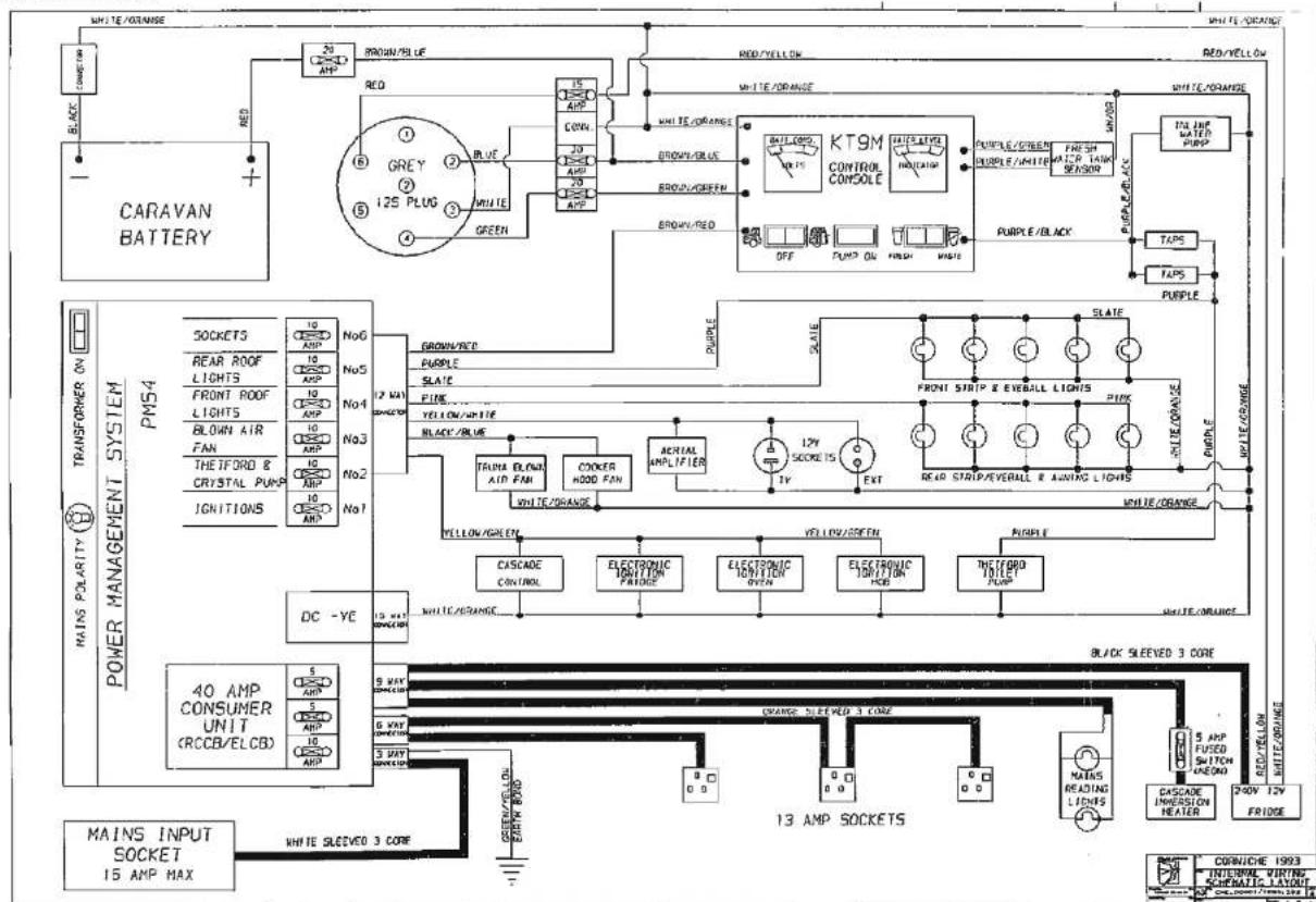
text_image
WHITE/ORANGE CARAVAN BATTERY GREEN/BLUE RED 15 CONV. 20 AHP 20 AHP GREEN WHITE/ORANGE WHITE/ORANGE GREEN/BLUE BROWN/RED BROWN/GREEN GREEN/RED KT9M CONTROL CONSOLE PULSE/GREEN FRESH LAMP 140k SENSOR OFF PUMP ON WHIP WHIP WHITE/ORANGE WHITE/ORANGE TAPS TAPS PURPLE PURPLE/BLACK WHITE/ORANGE TRANSFORMER ON POWER MANAGEMENT SYSTEM PM54 SOCKETS REAR ROOF LIGHTS FRONT ROOF LIGHTS BLOWN AIR FAN THEIFORD & CRYSTAL PUMP IGNITIONS No6 No5 No4 No3 No2 No1 12 WAT SPRINGER GROWN/RED PURPLE SLATE FINE YELLOW/WHITE BLACK/BLUE TRAVA BLOWN AID FAN COCKER HOOD FAN ACREAL AMPLIFIER 12V SOCKET 15 EXT REARD STRIP/VEEALL & AINTING LIGHTS WHITE/ORANGE WHITE/ORANGE WHITE/ORANGE WHITE/ORANGE CASCADE CONTROL ELECTRONIC ONION FRIDGE ELECTRONIC ONION OVEN ELECTRONIC ONION FOB THEFORD LOLET PLUMP DC -YE 15 WAT SPRINGER WHITE/ORANGE BLACK SLEEVED 3 CORE 40 AMP CONSUMER UNIT (RCCB/ELCB) 5 AMP 5 AMP 5 AMP 5 AMP 5 AMP 5 AMP 5 AMP 5 AMP 5 AMP 5 AMP 5 AMP 5 AMP 5 AMP 5 AMP 5 AMP 5 AMP 5 AMP 5 AMP 5 AMP 5 AMP 5 AMP 5 AMP 5 AMP 5 AMP 5 AMP 5 AMP 5 AMP 5 AMP 5 AMP 5 AMP 5 AMP 5 AMP 5 AMP 5 AMP 13 AMP SOCKETS MAINS INPUT SOCKET 15 AMP MAX WHITE SLEEVED 3 COREWiring Diagram
CONQUEROR (Interior)
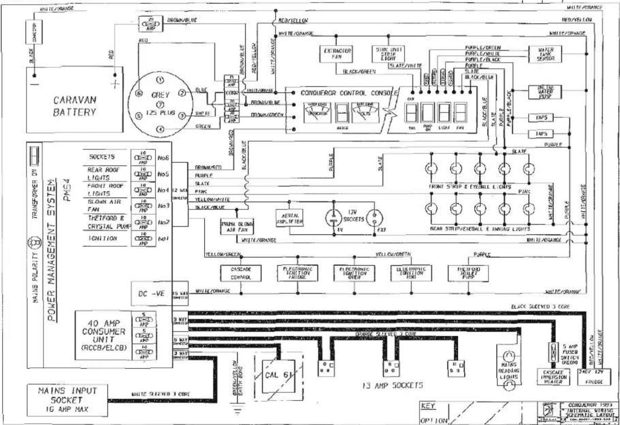
text_image
WHITE/ORANGE CARAVAN BATTERY GREEN RED/YELLOW WHITE/ORANGE RED/YELLOW WHITE/ORANGE EXTRIMETER FAN SILK UNIT STRIP LIGHT BLACK/GREEN CONQUEROR CONTROL CONSOLE SLATE/WHITE PAPLE/DRUM INVOICE SLATE/Black/BLUE PAPLE/DRUM INVOICE SLATE/Black/BLUE PAPLE/DRUM INVOICE SLATE/Black/BLUE PAPLE/DRUM INVOICE SLATE/Black/BLUE PAPLE/DRUM INVOICE SLATE/Black/BLUE PAPLE/DRUM INVOICE SLATE/Black/BLUE PAPLE/DRUM INVOICE SLATE/Black/BLUE PAPL/PUMP PUMP PUMP PUMP PUMP PUMP PUMP PUMP PUMP PUMP PUMP PUMP PUMP PUMP PUMP PUMP PUMP PUMP PUMP PUMP PUMP PUMP PUMP PUMP PUMP PUMP PUMP PUMP PUMP PUMP PUMP PUMP PUMP PUMP PWP PWP PWP PWP PWP PWP PWP PWP PWP PWP PWP PWP PWP PWP PWP PWP PWP PWP PWP PWP PWP PWP PWP PWP PWP PWP PWP PWP PWP PWP PWP PWP PWP PWPWiring Diagram
RAPIDE/SWIFT/CHALLENGER (Roadlight)
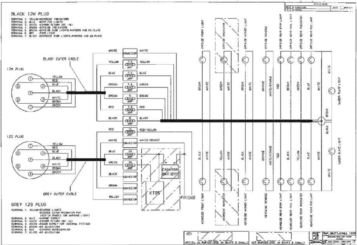
text_image
BLACK 12N PLUG TERMINAL 1. YELLOW-REVERSE INDICATORS TERMINAL 2. BLUE -BEAR FOR LIGHTS TERMINAL 3. WHITE -COMMON RETURN (DC-VB) TERMINAL 4. GREEN -OFFSIDE INDICATORS TERMINAL 5. GREEN -OFFSIDE SIDE LIGHTS, MARKERS AND NO.PLATE TERMINAL 6. RED -STOP LIGHT TERMINAL 7. BLACK-REVERSE SIDE LIGHTS, MARKERS AND NO.PLATE BLACK OUTER CABLE 12N PLUG ① YELLOW ② RED ③ BLACK ④ WHITE ⑤ BROWN ⑥ GREEN 12S PLUG ⑦ YELLOW ⑧ RED ⑨ BLUE ⑩ BLACK ⑪ WHITE ⑫ BROWN ⑬ GREEN ⑭ RED ⑮ BLACK 12S PLUG GREY OUTER CABLE GREY 12S PLUG TERMINAL 1. YELLOW-REVERSE LIGHTS REVERSE CABLE PROCAMATION FOR IMERTIA (IMRSES) (OR WARNING LIGHT) TERMINAL 2. BLUE -CHARGE SUPPLY TERMINAL 3. WHITE -COMMON RETURN (DC-VC) TERMINAL 4. GREEN -PODER SUPPLY FOR INTERNAL FITTING TERMINAL 5. BROWN -NO ALLOCATION TERMINAL 6. RED -CARAVAN REFRIGERATION TERMINAL 7. BLADE -NO ALLOCATION WHITE CONVECTOR WHITE YELLOW 7.5 AWP YELLOW BLUE 7.5 AWP BLUE GREEN 7.5 AWP GREEN BROWN 5 AWP BROWN RED 7.5 AWP RED BLACK 5 AWP BLACK RED YELLOW WHITE ORANGE WHITE ORANGE WHITE ORANGE CARAVAN BATTERY K795 IFRIDGE NEARSIDE FRUIT LIGHT NEARSIDE REVERSE NEARSIDE REAR STOP LIGHT NEARSIDE REAR TAIL LIGHT NEARSIDE REAR INDICATOR NEARSIDE REAR FOR LAMP KEY OPTION IN RAPITER STD IN SHIFT & CHALL? NET ROUTE STD IN SHIFT & CHALL? RAP, SHIFT, CHALL 1990
natural_image
Grayscale abstract texture with horizontal bands and no discernible text or symbols
CORNICHE (Roadlight)
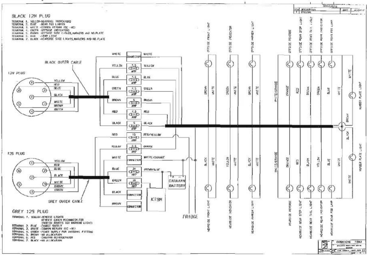
text_image
BLACK 12N PLUG TERMINAL 1. YELLOW-REVERSE INDICATORS TERMINAL 2. BLUE - REAR FOR LIGHTS TERMINAL 3. WHITE - CONVER RETURN IOC - NO TERMINAL 4. GREEN - OFFSIDE INDICATORS TERMINAL 5. BROWN - OFFSIDE SIDE LIGHTS, MARKERS AND NO.PLATE TERMINAL 6. RED - STOP LLOW TERMINAL 7. BLACK - REARSIDE SIDE LIGHTS, MARKERS AND NO.PLATE BLACK OUTER CABLE 12N PLUG YELLOW RED BLUE BLACK WHITE GREEN WHITE GREEN BLUE GREEN BROWN RED BLACK RED BLACK BLACK 12S PLUG YELLOW RED BLUE BLACK WHITE WHITE BROWN GREEN GREEN WHITE GREEN WHITE GREEN WHITE GREEN WHITE GREEN WHITE GREEN WHITE GREEN WHITE GREEN WHITE GREEN WHITE GREEN WHITE GREEN WHITE GREEN WHITE GREEN WHITE GREEN WHITE GREEN WHITE GREEN WHITE GREEN WHITE GREEN WHITE GREEN WHITE GREEN WHITE GREEN WHITE GREEN WHITE GREEN WHITE GREEN WHITE GREEN WHITE GREEN WHIP ZONE RENESE ORANGE RED BLUE GREEN WHITE GRASSER LIGHT SINGING PLET LIME OF CHINA GAMES & SLINKING PLET LIME OF CHINA GAMES & SLINKING PLET LIME OF CHINA GAMES & SLINKING PLET LIME OF CHINA GAMES & SLINKING PLET LIME OF CHINA GAMES & SLINKING PLET LIME OF CHINA GAMES & SLINKING PLET LIME OF CHINA GAMES & SLINKING PLET LIME OF CHINA GAMES & SLINKING PLET LIME OF CHINAWiring Diagram

natural_image
Pure grayscale horizontal bar with no text, numbers, or symbolsCONQUEROR (Roadlight)
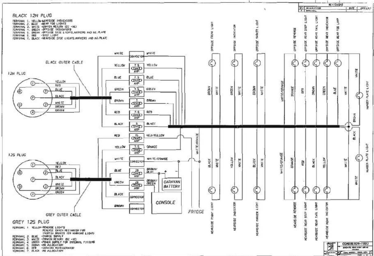
text_image
BLACK 12N PLUG TERMINAL 1. YELLOW-NEARSIDE INDICATORS TERMINAL 2. BLUE - NEARF FOR LIGHTS TERMINAL 3. WHITE - DOWN RETURN DC + VCI TERMINAL 4. GREEN - OFFSIDE INDICATORS TERMINAL 5. BROWN - OFFSIDE SIDE LIGHTS, MARKERS AND NO.PLATE TERMINAL 6. RED - SIDE LIGHT TERMINAL 7. BLACK-NEARSIDE SIDE LIGHTS, MARKERS AND NO.PLATE BLACK OUTER CABLE 12N PLUG ① YELLOW RED BLUE BLACK WHITE BROWN GREEN 12S PLUG ② YELLOW RED BLUE BLACK WHITE BROWN GREEN GREY OUTER CABLE GREEN OUTER CABLE GREEN OUTER CABLE GREEN OUTER CABLE GREEN OUTER CABLE GREEN OUTER CABLE GREEN OUTER CABLE GREEN OUTER CABLE GREEN OUTER CABLE GREEN OUTER CABLE GREEN OUTER CABLE GREEN OUTER CABLE GREEN OUTER CABLE GREEN OUTER CABLE GREEN OUTER CABLE GREEN OUTER CABLE GREEN OUTER CABLE GREEN OUTER CABLE GREEN OUTER CABLE GREEN OUTER CABLE GREEN OUTER CABLE GREEN OUTER CABLE
natural_image
Pure horizontal line pattern without any text, numbers, or symbols
WATER
| Problem | Possible Cause | Remedy |
| Water not flowing from any tap when operated but pump runs | Freshwater tank emptyPump wired in reversePump not primedPipe Inlet or outlet pipe disconnectedPump pipes restricted by kinkingBlockage in pump inlet or outlet pipeBlocked in-line filter of pump filterAir leak in suction line to pump | CheckCheck wiring, refer to pump manufacturers instructionsRefer to pump manufacturers instructionCheck connectionsCheck pipes runCheck, starting inside freshwater tankDismantle and cleanCheck for bubbles & secure with clip |
| Pump does not run | Pump or tap incorrectly wiredPump fuse blownBattery disconnectedPump seized or overheatedPressure pump sensing switch may have failed | Refer to pump/tap manufacturers instructionsCheck wiring connection and then replace with fuse of correct ratingCheck connectionsRefer to pump manufacturers servicing instructionsRefer to pump manufacturers servicing instructions |
| Water flows from cold tap but not from hot | Feed pipe to water heater incorrectly connected to the heater outletBlockage in hot pipelineHeater inlet or outlet pipes kinked preventing flowHot tap not connectedHot tap failed or blockedHeater non-return valve jammed | Refer to installation instructionsDisconnect pipes and inspectCheck and re-route if necessary. Ensure that hose is Carver recommended typeRefer to installation manualDisconnect and inspectSeek service attention |
| Water flows from hot tap but has reduced flow from cold | Cold water pipe kinked preventing flowBlockage in cold pipe lineCold tap not connectedCold tap failed or blockedIf a Carver Crystal water service unit is fitted the cartridge is exhausted | Check and re-route if necessaryDisconnect pipes after 1st Y connector and check up to tapRefer to installation instructionsDisconnect and inspectReplace cartridge |
| Reduced flow from both hot and cold taps | Battery condition low causing pump to run slowlyIf new taps have been fitted they may be restricting flowPump needs servicingPartially blocked pump filter or in-line filter, if fittedPump outlet pipe kinked restricting flowWater leak | Check battery state of charge refer to electrical supply noteDisconnect and check that they have at least 14'' (6.3mm) boreRefer to pump servicing instructionsDismantle and clean if necessaryCheck and re-route if necessaryCheck all water connections |
| Reduced flow from either tap | 'Y' connector(s) fitted IncorrectlyPipe kinking restricting flowBore size difference in taps | Refer to installation instructionsCheck and re-route if necessaryUse taps of equal bore size |
| Warm water flows out of cold tap | Hot water back feeding into cold line, usually if mixer tap or single outlet hot and cold taps being used | Fit non-return valve in cold supply near tap |
Fault Finding

natural_image
Grayscale abstract texture with horizontal bands and no visible text or symbolsGAS
| Problem | Possible Cause | Remedy |
| Hob does not light | No gasAir in pipe | Check level of gas in bottleCheck gas bottle valve is onCheck gas taps are onPurge systemRefer to hob manufacturers instructions |
| Oven does not light | No gasAir in pipe | Check level of gas in bottleCheck gas bottle valve is onCheck gas taps are onPurge systemRefer to oven manufacturers instructions |
| Space heater or central heating boiler does not light | No gasOver gassedAir in pipe | Check level of gas in bottleCheck gas bottle valve is onCheck gas taps are onCheck exhaust outlet is clearTurn off appliance, wait 2 minutes and try againPurge systemRefer to space heater or central heating boiler manufacturers instructions |
| Fridge does not light | No gasAir in pipe | Check level of gas in bottleCheck gas bottle valve is onCheck gas taps are onPurge systemRefer to fridge manufacturers instructions |
| Water heater does not light | No gasAir in pipe | Check level of gas in bottleCheck gas bottle valve is onCheck gas taps are onPurge systemRefer to water heater manufacturers instructions |
Fault Finding
FAULT FINDING - CASSETTE TOILET
| Problem | Remedy |
| Bowl does not drain when toilet is flushed. Cassette is overfilled. | DO NOT REMOVE CASSETTE. While inside the caravan turn flush knob anti-clockwise to open valve blade and leave it in the open position.Open access door on side of caravan. Rotate pour-out spout outward. Place appropriate size container under spout cap. Remove cap carefully. Allow bowl contents to drain into container. This will lower the water level in the bowl. Replace cap and return pour-out spout to stored position. DO NOT REMOVE CASSETTE.Go inside the caravan and turn the flush knob clockwise to close valve blade. Now, the cassette may be removed following the normal removal and emptying procedure. |
| Odcurs | Use proper amount of holding tank deodorant specified on bottle. |
| Toilet tissue does not fit into compartment. | Since some tissues are supplied on larger rolls, it may be necessary to use some tissue before storing into compartment. |
| Soiled bowl after flushing | Partially fill bowl to cover soiled portion of bowl. Next flush will dissolve waste.Tip: Leave valve blade open during use. |
| No power to add water to toilet bowl | Check cassette safety sensor switch and fuse-holder for proper engagement and operation.Note: Cassette has to be removed to reach switch and fuse.Insert cassette and try adding water to toilet bowl.Toilet can be flushed manually. Add water. Add water to bowl from a separate container. Turn flush knob anti-clockwise to open valve blade. Turn clockwise to close valve blade. |
| Cassette cannot be removed | Check for obstacles under retaining clip. Depress retaining clip several times to check operation. Remove cassette.Flush knob and valve blade in partial open position. Close valve blade by moving knob clockwise.CAUTION: If valve blade is open during cassette removal, severe damage to system can occur. Never force insertion or removal of the cassette tank. |
| Valve blade mechanism sticks or is hard to open. | Spray light film of silicone on blade. |
| Major unit malfunction | Contact your original Caravan Dealer. |
Specification
| RAPIDE | 300/2 | 400/4 | 430/4 | 440/4 | 450/5 | 490/5 |
| Internal Body Lengthat Bedbox Height | 12' 7"3.84m | 13' 2"4.00m | 14' 6"4.43m | 14' 9"4.51m | 14' 9"4.51m | 16' 1"4.90m |
| Body Width(incl. extrusions) | 7' 0"2.13m | 7' 0"2.13m | 7' 0"2.13m | 7' 0"2.13m | 7' 0"2.13m | 7' 0"2.13m |
| Shipping Length | 17' 2"5.24m | 17' 9"5.40m | 19' 2"5.83m | 19' 5"5.90m | 19' 5"5.90m | 20' 8"6.30m |
| MaximumExternal Height | 8' 3"2.51m | 8' 3"2.51m | 8' 3"2.51m | 8' 3"2.51m | 8' 3"2.51m | 8' 3"2.51m |
| MaximumHeadroom | 6' 3"1.91m | 6' 3"1.91m | 6' 3"1.91m | 6' 3"1.91m | 6' 3"1.91m | 6' 3"1.91m |
| Height to Centreof Tow Ball (ex Works ±30mm) | 16.5"415mm | 16.5"415mm | 16.5"415mm | 16.5"415mm | 16.5"415mm | 16.5"415mm |
| Berths | 2 | 4 | 4 | 4 | 5 | 5 |
| Ex-Works Weight±5% | 13.3 cwt*675 kg | 13.9 cwt*705 kg | 14.8 cwt*755 kg | 15.2 cwt770 kg | 15.3 cwt*700 kg | 16.7 cwt850 kg |
| Caravan AllowablePayload | 3.4 cwt*175 kg | 4.8 cwt*245 kg | 3.9 cwt*195 kg | 4.5 cwt*230 kg | 4.4 cwt*220 kg | 4.1 cwt*210 kg |
| Maximum Authorised Weight | 16.7 cwt850 kg | 18.7 cwt950 kg | 18.7 cwt950 kg | 19.7 cwt1000 kg | 19.7 cwt1000 kg | 20.8 cwt1060 kg |
| Tyre Sizes | 155R 13Radial | 155R 13Reinforced Radial | 155R 13Reinforced Radial | 165R 13Reinforced Radial | 165R 13Reinforced Radial | 165R 13Reinforced Radial |
| Tyre Pressures | 33 p.s.i.2.3 bar | 42 p.s.i.3.0 bar | 42 p.s.i.3.0 bar | 42 p.s.i.3.0 bar | 42 p.s.i.3.0 bar | 42 p.s.i.3.0 bar |
| Bed Sizes (cms) | 1 × 201 × 152or2 × 191 × 69 | 1 × 201 × 1352 × 201 × 76 | 1 × 201 × 1351 × 187 × 601 × 173 × 60 | 1 × 201 × 152 or1 × 191 × 76 and1 × 201 × 76 and2 × 201 × 76 | 1 × 201 × 1351 × 183 × 1151 × 201 × 69 | 1 × 201 × 152 or2 × 191 × 69 and1 × 201 × 7151 × 201 × 69 |
| Ground to GroundAwning Channel Sizes | 26' 3"8.00m | 26' 9"8.16m | 26' 2"8.59m | 28' 5"8.66m | 28' 5"8.66m | 29' 9"9.06m |
* Estimated
Specification
| SWIFT DIAMOND | MINUETTE | SILHOUETTE | CORVETTE | DANETTE | CORONETTE | DOUBLETTE | PIROUETTE | ALOUETTE |
| Internal Body Lengthat Bedbox Height | 11' 10"3.58m | 13' 3"4.05m | 15' 0"4.57m | 15' 1"4.59m | 15' 3"4.65m | 15' 3"4.65m | 15' 4"4.76m | 16' 11"5.15m |
| Body Width(incl. extrusions) | 7' 0"2.13m | 7' 0"2.13m | 7' 0"2.13m | 7' 0"2.13m | 7' 0"2.13m | 7' 0"2.13m | 7' 0"2.13m | 7' 0"2.13m |
| Shipping Length | 16' 7"5.06m | 18' 2"5.52m | 19' 10"6.04m | 19' 11"6.06m | 20' 1"6.12m | 20' 1"6.12m | 20' 5"6.23m | 21' 9"6.62m |
| MaximumExternal Height | 8' 3"2.51m | 8' 3"2.51m | 8' 3"2.51m | 8' 3"2.51m | 8' 3"2.51m | 8' 3"2.51m | 8' 3"2.51m | 8' 3"2.51m |
| MaximumHeadroom | 6' 3"1.91m | 6' 3"1.91m | 6' 3"1.91m | 6' 3"1.91m | 6' 3"1.91m | 6' 3"1.91m | 6' 3"1.91m | 6' 3"1.91m |
| Height to Centreof Tow Ball (ex Works ±30mm) | 16.5"415mm | 16.5"415mm | 16.5"415mm | 16.5"415mm | 16.5"415mm | 16.5"415mm | 16.5"415mm | 16.5"415mm |
| Berths | 2 | 2 | 4 | 5 | 2 | 2 | 4 | 5 |
| Ex-Works Weight±5% | 13.8 cwt*700 kg | 14.7 cwt745 kg | 16.5 cwt840 kg | 16.5 cwt840 kg | 16.7 cwt*850 kg | 16.7 cwt*850 kg | 16.8 cwt*855 kg | 18.6 cwt945 lg |
| Caravan AllowablePayload | 3.9 cwt*200 kg | 3.0 cwt155 kg | 4.3 cwt220 kg | 4.3 cwt220 kg | 4.1 cwt*210 kg | 4.1 cwt*210 kg | 4.0 cwt*205 kg | 4.0 cwt205 kg |
| Maximum AuthorisedWeight | 17.7 cwt900 kg | 17.7 cwt900 kg | 20.8 cwt1060 kg | 20.8 cwt1060 kg | 20.8 cwt1060 kg | 20.8 cwt1060 kg | 20.8 cwt1060 kg | 22.6 cwt1150 kg |
| Tyre Sizes (Radial) | 155R 13Reinforced | 155R 13Reinforced | 165R 13Reinforced | 165R 13Reinforced | 165R 13Reinforced | 165R 13Reinforced | 165R 13Reinforced | 175R 13Reinforced |
| Tyre Pressures | 42 p.s.i.3.0 bar | 42 p.s.i.3.0 bar | 42 p.s.i.3.0 bar | 42 p.s.i.3.0 bar | 42 p.s.i.3.0 bar | 42 p.s.i.3.0 bar | 42 p.s.i.3.0 bar | 42 p.s.i.3.0 bar |
| Bed Sizes (cms) | 1 × 201 × 142or1 × 191 × 69and1 × 183 × 69 | 1 × 201 × 152or2 × 191 × 69 | 1 × 201 × 152or2 × 191 × 69and2 × 201 × 76 | 1 × 201 × 1351 × 183 × 115or1 × 183 × 691 × 201 × 69 | 1 × 201 × 152or2 × 191 × 69 | 1 × 201 × 152or2 × 191 × 69 | 1 × 201 × 1352 × 180 × 58 | 1 × 201 × 152 or2 × 191 × 691 × 183 × 115 or1 × 183 × 691 × 201 × 69 |
| Ground to GroundAwning Channel Sizes | 24' 11"7.60m | 26' 5"8.06m | 28' 3"8.60m | 28' 3"8.60m | 28' 5"8.66m | 28' 5"8.66m | 28' 6"8.69m | 30' 0"9.16m |
* Estimated
Specification
| CHALLENGER SE | 360 | 400 | 440 | 450 | 470 | 480 | 490 | 490L | 510 |
| Internal Body Lengthat Bedbox Height | 11' 10"3.58m | 13' 10"4.22m | 15' 2"4.62m | 15' 0"4.59m | 15' 3"4.65m | 15' 3"4.65m | 16' 11"5.15m | 16' 11"5.15m | 16' 9"5.10m |
| Body Width(incl, extrusions) | 7' 0"2.13m | 7' 0"2.13m | 7' 0"2.13m | 7' 0"2.13m | 7' 0"2.13m | 7' 0"2.13m | 7' 0"2.13m | 7' 0"2.13m | 7' 0"2.13m |
| Shipping Length | 16' 7"5.06m | 18' 8"5.69m | 20' 0"6.10m | 19' 11"6.06m | 20' 1"6.13m | 20' 1"6.13m | 21' 9"6.62m | 21' 9"6.62m | 21' 7"6.58m |
| MaximumExternal Height | 8' 3"2.51m | 8' 3"2.51m | 8' 3"2.51m | 8' 3"2.51m | 8' 3"2.51m | 8' 3"2.51m | 8' 3"2.51m | 8' 3"2.51m | 8' 3"2.51m |
| MaximumHeadroom | 6' 3"1.91m | 6' 3"1.91m | 6' 3"1.91m | 6' 3"1.91m | 6' 3"1.91m | 6' 3"1.91m | 6' 3"1.91m | 6' 3"1.91m | 6' 3"1.91m |
| Height to Centreof Tow Ball (ex Works ±30mm) | 16.5"415mm | 16.5"415mm | 16.5"415mm | 16.5"415mm | 16.5"415mm | 16.5"415mm | 16.5"415mm | 16.5"415mm | 16.5"415mm |
| Berths | 2 | 2 | 4 | 5 | 2 | 2 | 5 | 5 | 4 |
| Ex-Works Weight±5% | 14.0 cwt710 kg | 16.8 cwt*855 kg | 17.7 cwt900 kg | 17.7 cwt*900 kg | 17.9 cwt910 kg | 18.1 cwt*920 kg | 18.9 cwt960 kg | 19.2 cwt975 kg | 18.7 cwt950 kg |
| Caravan AllowablePayload | 3.7 cwt190 kg | 4.0 cwt*205 kg | 4.9 cwt250 kg | 4.9 cwt*250 kg | 4.7 cwt240 kg | 4.5 cwt*230 kg | 4.7 cwt240 kg | 4.4 cwt225 kg | 4.9 cwt250 kg |
| Maximum Authorised Weight | 17.7 cwt900 kg | 20.8 cwt1060 kg | 22.6 cwt1150 kg | 22.6 cwt1150 kg | 22.6 cwt1150 kg | 22.6 cwt1150 kg | 23.6 cwt1200 kg | 23.6 cwt1200 kg | 23.6 cwt1200 kg |
| Tyre Sizes | 155R 13ReinforcedRadial | 165R 13ReinforcedRadial | 175R 13ReinforcedRadial | 175R 13ReinforcedRadial | 175R 13ReinforcedRadial | 175R 13ReinforcedRadial | 175R 136 ply | 175R 136 ply | 175R 136 ply |
| Tyre Pressures | 42 p.s.i.3.0 bar | 42 p.s.i.3.0 bar | 42 p.s.i.3.0 bar | 42 p.s.i.3.0 bar | 42 p.s.i.3.0 bar | 42 p.s.i.3.0 bar | 46 p.s.i.3.3 bar | 46 p.s.i.3.3 bar | 46 p.s.i.3.3 bar |
| Bed Sizes (cms) | 1×197×142or1×191×66and1×183×66 | 1×197×152or2×191×66 | 1×197×152 or2×191×66 and1×197×761×201×76 | 1×197×1351×180×115 or1×180×691×201×69 | 1×197×152 or2×191×66 | 1×197×152 or2×191×66 | 1×197×152 or2×191×661×197×1151×201×69 | 1×197×152 or2×191×661×180×116 or1×180×691×201×69 | 1×197×152 or2×191×66 and2×180×60 |
| Ground to GroundAwning Channel Sizes | 24' 11"7.60m | 27' 1"8.23m | 28' 5"8.65m | 28' 3"8.60m | 20' 5"8.65m | 20' 5"8.65m | 30' 0"9.16m | 30' 0"9.16m | 29' 11"9.13m |
* Estimated

natural_image
Grayscale abstract texture with horizontal striations and no discernible text or symbolsSpecification
| CORNICHE | 12/2 | 15/2 | 15/2E | 15/4 |
| Internal Body Lengthat Bedbox Height | 12' 5"3.78m | 15' 3"4.65m | 15' 3"4.65m | 15' 3"4.65m |
| Body Width(incl. extrusions) | 7' 0"2.13m | 7' 0"2.13m | 7' 0"2.13m | 7' 0"2.13m |
| Shipping Length | 18' 0"5.47m | 20' 10"6.35m | 20' 10"6.35m | 20' 10"6.35m |
| MaximumExternal Height | 8' 1"2.47m | 8' 1"2.47m | 8' 1"2.47m | 8' 1"2.47m |
| MaximumHeadroom | 6' 3"1.91m | 6' 3"1.91m | 6' 3"1.91m | 6' 3"1.91m |
| Height to Centreof Tow Ball (ex Works ±30mm) | 16.5"415mm | 16.5"415mm | 16.5"415mm | 16.5"415mm |
| Berths | 2 | 2 | 2 | 4 |
| Ex-Works Weight±5% | 16.5 cwt840 kg | 18.5 cwt940 kg | 18.3 cwt*930 kg | 18.9 cwt*960 kg |
| Caravan AllowablePayload | 4.3 cwt220 kg | 4.1 cwt210 kg | 4.3 cwt*220 kg | 3.7 cwt*190 kg |
| Maximum Authorised Weight | 20.8 cwt1060 kg | 22.6 cwt1150 kg | 22.6 cwt1150 kg | 22.6 cwt1150 kg |
| Tyre Sizes | 165R 13Reinforced Radial | 175R 13Reinforced Radial | 175R 13Reinforced Radial | 175R 13Reinforced Radial |
| Tyre Pressures | 42 p.s.i.3.0 bar | 46 p.s.i.3.3 bar | 46 p.s.i.3.3 bar | 46 p.s.i.3.3 bar |
| Bed Sizes (cms) | 1 × 197 × 142or2 × 183 × 66 | 1 × 197 × 152or2 × 191 × 66 | 1 × 197 × 1522 × 191 × 66 | 1 × 197 × 152or2 × 191 × 66and1 × 197 × 761 × 201 × 76 |
| Ground to GroundAwning Channel Sizes | 25' 0"7.61m | 27' 4"8.34m | 27' 4"8.34m | 27' 4"8.34m |
| CAPPUCCINO | |
| Internal Body Lengthat Bedbox Height | 11' 10"3.58m |
| Body Width(incl. extrusions) | 7' 0"2.13m |
| Shipping Length | 16' 7"5.06m |
| MaximumExternal Height | 8' 3"2.51m |
| MaximumHeadroom | 6' 3"1.91m |
| Height to Centreof Tow Ball (ex Works ± 30mm) | 16.5"415mm |
| Berths | 2 |
| Ex-Works Weight±5% | 14.0 cwt710 kg |
| Caravan AllowablePayload | 3.7 cwt190 kg |
| Maximum Authorised Weight | 17.7 cwt900kg |
| Tyre Sizes | 155R 13Reinforced Radial |
| Tyre Pressures | 42 p.s.i.3.0 bar |
| Bed Sizes (cms) | 1 × 201 × 142or1 × 191 × 66and1 × 183 × 66 |
| Ground to GroundAwning Channel Sizes | 24' 11"7.60m |
* Estimated


natural_image
Grayscale abstract texture with vertical striations and horizontal bands, no text or symbols visible| CONQUEROR | 520 LUX | 550 LUX | 640 LUX | 640 SALON |
| Internal Body Lengthat Bedbox Height | 17' 3"5.25m | 18' 10"5.50m | 20' 10"6.35m | 20' 10"6.35m |
| Body Width(incl. extrusions) | 7' 3"2.22m | 7' 3"2.22m | 7' 3"2.22m | 7' 3"2.22m |
| Shipping Length | 22' 1"6.73m | 22' 10"6.97m | 25' 8"7.84m | 25' 8"7.84m |
| MaximumExternal Height | 8' 5"2.57m | 8' 5"2.57m | 8' 5"2.57m | 8' 5"2.57m |
| MaximumHeadroom | 6' 3"1.91m | 6' 3"1.91m | 6' 3"1.91m | 6' 3"1.91m |
| Height to Centreof Tow Ball (ex Works ±30mm) | 16.5"415mm | 16.5"415mm | 16.5"415mm | 16.5"415mm |
| Berths | 4 | 5 | 5 | 4 |
| Ex-Works Weight±5% | 20.7 cwt1050 kg | 22.6 cwt1150 kg | 24.3 cwt*1235 kg | 24.1 cwt1225 kg |
| Caravan AllowablePayload | 4.9 cwt250 kg | 8.9 cwt450 kg | 7.2 cwt*365 kg | 7.4 cwt375 kg |
| Maximum Authorised Weight | 25.6 cwt1300 kg | 31.5 cwt1600 kg | 31.5 cwt1600 kg | 31.5 cwt1600 kg |
| Tyre Sizes | 175R 136 ply | 155R 13Radial | 155R 13Radial | 155R 13Radial |
| Tyre Pressures | 50 p.s.i.3.5 bar | 33 p.s.i.2.3 bar | 33 p.s.i.2.3 bar | 33 p.s.i.2.3 bar |
| Bed Sizes (cms) | 1 × 206 × 1351 × 190 × 123 | 1 × 206 × 152or2 × 191 × 661 × 206 × 1151 × 210 × 69 | 1 × 206 × 152or2 × 191 × 661 × 180 × 662 × 180 × 60 | 1 × 206 × 152or2 × 191 × 661 × 191 × 140or1 × 191 × 68 |
| Ground to GroundAwning Channel Sizes | 30' 5"9.27m | 31' 3"9.52m | 34' 0"10.37m | 34' 0"10.37m |
* Estimated

natural_image
Grayscale abstract texture with no discernible text, symbols, or structured elements
FITTED EQUIPMENT LIST
| EQUIPMENT | MANUFACTURER/MODEL | RAPIDE | SWIFT | CAPPUCCINO | CHALLENGER | CORNICHE | CONQUEROR | CONQUEROR |
| ALL MODELS | ALL MODELS | SE MODELS | ALL MODELS | 520 & 550 | 640 | |||
| E.L.C.B. | - PLUG-IN SYSTEMS - C.E.C. 25 | ■ | ||||||
| POWER MANAGEMENT SYSTEM | - PLUG-IN SYSTEMS - P.M.S. 4 | ■ | ■ | ■ | ■ | ■ | ■ | |
| TRANSFORMER/CHARGING UNIT | - PLUG-IN SYSTEMS - KT12SM | OPT | ■ | ■ | ■ | ■ | ■ | ■ |
| 12v DISTRIBUTION PANEL | - PLUG-IN SYSTEMS - KT9S2 | OPT | ■ | ■ | ■ | |||
| - KT9/640 | ■ (550) | ■ | ||||||
| - KT9M | ■ | ■ (520) | ||||||
| MAINS ELECTRIC SOCKETS | 1 | 2 | 2 | 3 | 3 | 3 | 3 | |
| 12v SOCKETS | 1 | 1 | 1 | 1 | 1 | 1 | 2 | |
| MAINS READING LIGHTS | ■ | ■ | ■ | ■ | ||||
| 12v READING LIGHTS | ■ | ■ | ■ | ■ | ■ | ■ | ||
| FLUORESCENT LIGHTS | ■ | ■ | ■ | ■ | ■ | ■ | ■ | |
| AWNING LIGHT | ■ | ■ | ■ | ■ | ■ | ■ | ■ | |
| T.V. AERIAL SOCKETS | 1 | 1 | 1 | 1 | 2 | |||
| MAXVIEW CAZELLE AERIAL | ■ | ■ | ■ | |||||
| REVERSING LIGHTS | ■ | ■ | ■ | |||||
| SIDE REPEATER FLASHERS | ■ | ■ | ■ | ■ | ■ | ■ | ||
| CLOCK | ■ | ■ | ■ | ■ | ■ | ■ | ||
| MAINS LEAD (20 metres) | ■ | ■ | ■ | ■ | ■ | ■ | ■ | |
| SMOKE ALARM (DICON) | ■ | ■ | ■ | ■ | ■ | ■ | ■ | |
| WATER PUMP | - CARVER CRYSTAL FILTER - TRENT | ■ | ||||||
| - THAMES | ■ | ■ | ■ | |||||
| - WHALE G.P. 8080B | ■ | ■ | ■ | |||||
| - WHALE G.P. 99 | ■ | ■ | ||||||
| - WHALE G.P. 88 | ■ | |||||||
| TAPS | - WHALE | ■ | ■ | ■ | ■ | ■ | ■ | |
| - KELLER | ■ | |||||||
| WATER HEATER | - CARVER CASCADE 2GE (DUAL POWER) | OPT | ■ | ■ | ■ | ■ | ■ | ■ |
| FITTED SHOWER WITH RISER BAR | ■ | ■ | ■ | ■ | ■ | |||
| FITTED SHOWER - NO RISER BAR | OPT | ■ | ||||||
| VANITY UNIT | ■ | ■ | ■ | ■ | ■ | ■ | ■ | |
| SHOWER TRAY | ■ | ■ | ■ | ■ | ■ | ■ | ■ | |
| SHOWER TRAY MAT | ■ | ■ | ■ | ■ | ■ | ■ | ||
| CASSETTE TOILET WITH MANUAL FLUSH (OPT, ELECTRIC FLUSH) | ■ | ■ | ■ | ■ | ■ | ■ | ■ | |
| INBOARD WATER PIPES | ■ | ■ | ■ | ■ | ■ | ■ | ■ | |
| INBOARD WATER TANK (9 gallons) | ■ | ■ | ■ | |||||
| HEATING | - CARVER 1.8kW | ■ | ■ | ■ | ||||
| - CARVER TRUMATIC 3kW | ■ | ■ | ■ | |||||
| - CARVER TRUMATIC 5kW | ■ | |||||||
| - BLOWN AIR SYSTEM | ■ | ■ | ■ | ■ | ||||
Equipment List
FITTED EQUIPMENT LIST (continued)
| EQUIPMENT | MANUFACTURER/MODEL | RAPIDE | SWIFT | CAPPUCCINO | CHALLENGER | CORNICHE | CONQUEROR | CONQUEROR |
| ALL MODELS | ALL MODELS | SE MODELS | ALL MODELS | 520 & 550 | 640 | |||
| REFRIGERATOR | - ELECTROLUX 60 LT | ■ | ■ | |||||
| - ELECTROLUX 70 LT (Elec. Ignition) | ■ | ■ | ■ | ■ | ||||
| - ELECTROLUX 77 LT (Elec. Ignition) | ■ | |||||||
| HOB UNIT | - CRAMER - STAINLESS STEEL - 3 BURNER | ■ | ||||||
| - ENAMELLED - 3 BURNER | ■ | ■ | ||||||
| - 4 BURNER (Elec. Ignition) | ■ | ■ | ■ | ■ | ||||
| OVEN | - MAXOL 3000 | OPT | OPT | |||||
| - MAXOL 3000i (Electronic Ignition) | ■ | ■ | ||||||
| - MAXOL 3000Ti (Elec. Ign. & Thermostatic Control) | ■ | ■ | ■ | |||||
| INTERNAL BATTERY BOX | OPT | |||||||
| EXTERNAL ACCESS BATTERY BOX | OPT | ■ | ■ | ■ | ■ | ■ | ■ | |
| DOUBLE CLAZING WITH NIGHT LATCH VENTILATION | ■ | ■ | ■ | ■ | ■ | ■ | ■ | |
| THREE OPENING FRONT WINDOWS | ■ | ■ | ■ | ■ | ■ | ■ | ■ | |
| WINDOW BLINDS AND FLYSCREEN | ■ | ■ | ■ | ■ | ■ | |||
| EXTERIOR DOOR WITH WINDOW BLIND | ■ | ■ | ■ | ■ | ■ | ■ | ■ | |
| ROOF LIGHTS WITH BLIND AND FLYSCREEN | ■ | ■ | ■ | ■ | ■ | ■ | ||
| LINED VELVET CURTAINS | ■ | ■ | ■ | ■ | ■ | ■ | ||
| UNLINED VELVET CURTAINS | ■ | |||||||
| TWO BOLSTER AND SCATTER CUSIONS (6' 3" BEDS) | ■ | ■ | ■ | ■ | ■ | ■ | ||
| PULL OUT ROLLER SLATTED BEDS | ■ | ■ | ■ | ■ | ■ | ■ | ■ | |
| FREE STANDING TABLE | ■ | ■ | ■ | ■ | ■ | ■ | ■ | |
| TABLE STORAGE LOCKER | ■ | ■ | ■ (not 12/2) | ■ | ■ | |||
| TABLE STORAGE IN TOILET COMPARTMENT | ■ | ■ | ■ (12/2 only) | |||||
| DRAWER UNIT WITH OCCASIONAL TABLE | ■ | ■ | ■ | ■ | ■ | ■ | ||
| SOLID ASH FRAMED FURNITURE DOORS | ■ | ■ | ■ | ■ | ■ | |||
| WINDSOR OAK STYLE FRAMED FURNITURE DOORS | ■ | ■ | ||||||
| COCKTAIL CABINET (NOT DAN, CORV, ALOU, CHALL 459) | ■ | ■ | ■ | ■ | ■ | ■ | ||
| KITCHEN WINDOW BLIND | ■ | ■ | ■ | ■ | ■ | ■ | ■ | |
| DOOR MAT TRAY WITH BRUSH OUT FACILITY | ■ | ■ | ■ | ■ | ■ | |||
| FRONT REFLECTORS AND SIDE MARKERS | ■ | ■ | ■ | ■ | ■ | ■ | ■ | |
| SPARE WHEEL | ■ | ■ | ■ | |||||
| SCISSOR JACK | ■ | ■ | ■ | |||||
| CHASSIS | - AL-KO | ■ | ■ | ■ | ■ | ■ | ■ | |
| - SYSPAL | ■ | |||||||
| RUNNING GEAR | - AL-KO | ■ | ■ | ■ | ■ | ■ | ■ | ■ |
Bulb Replacement
LIGHT REPLACEMENT TABLE
| RAPIDE | SWIFT | CAPPUCCINO | CHALLENGER SE | CORNICHE | CONQUEROR | |||
| ROAD LIGHTS | TYPE | POWER | ||||||
| Front Marker | 239 | 12V 5W | ■ | ■ | ■ | ■ | ■ | ■ |
| Side Marker | 239 | 12V 5W | ■ | ■ | ■ | ■ | ■ | ■ |
| Tail | 245 | 12V 10W | ■ | ■ | ||||
| Tail/Brake | 380 | 12V 21/5W | ■ | ■ | ■ | ■ | ■ | |
| Fog | 382 | 12V 21W | ■ | ■ | ■ | ■ | ■ | ■ |
| Reversing | 382 | 12V 21W | ■ | ■ | ■ | ■ | ■ | |
| Brake | 382 | 12V 21W | ■ | ■ | ||||
| Rear Indicator | 382 | 12V 21W | ■ | ■ | ■ | ■ | ■ | ■ |
| Side Indicator | 239 | 12V 5W | ■ | ■ | ■ | ■ | ■ | |
| Number Plate | 245 | 12V 10W | ■ | ■ | ■ | ■ | ■ | |
| Number Plate | 239 | 12V 5W | ■ | |||||
| INTERIOR/OTHER | ||||||||
| Awning | 245 | ■ | ■ | ■ | ■ | ■ | ||
| Eyeball reading | 245 | ■ | ■ | ■ | ■ | ■ | ||
| Spare wheel locker | 239 | ■ | ||||||
| Double & single roof | ■ | ■ | ■ | ■ | ■ | |||
| Vanity fittings | Fluorescent 300mm | 12V 8W | ■ | ■ | ■ | ■ | ■ | ■ |
| Console unit | Fluorescent 530mm | 12V 13W | ||||||
| Mains reading | Small screw fitting (round) | 240V 25W | ■ | ■ | ■ | |||
Useful Information
Swift Owners Club
The Swift Owners Club is a completely independent organisation run for the benefit of Swift owners. They have numerous rallies during the year in various parts of the country and every second year Swift Group Ltd. sponsor a 'Works Rally' where owners have the opportunity to visit the factory. Apart from the friendliness and companionship the Club generates it is also actively engaged in charity work for those less fortunate than ourselves. The address of the Secretary of the Swift Owners Club can be obtained from Swift Caravans.
Swift Spares and After Sales
There are numerous items available from your dealer in the specially packaged 'Swift Spares', ranging from door catches through to spare wheels and touch-up paints. Please note that all after sales enquiries must be directed through your supplying dealer. The after sales service at the factory is geared to support our dealer network as is the service provided by appliance manufacturers.
NB Please remember to quote chassis number when ordering any items from either your dealer or Swift manufacturers.
Repair Facilities
Should you be unfortunate enough to suffer a major accident with your caravan it is comforting to know that Swift have a completely separate repair shop facility where their fully trained experts will undertake all types of major damage repair work.
Repairs of a minor nature should be referred first to your local dealer.
The enjoyment of caravanning can be greatly enhanced by membership of one or more of the various caravanning, motoring and holiday clubs. Here are some useful addresses:
The Caravan Club, East Grinstead House, East Grinstead
West Sussex, RH19 IUA (Tel: 0342 326944)
The Camping and Caravanning Club, Ensign Business Centre, Westwood Business Park, Coventry,
West Midlands. (Tel: 0203 694995)
Automobile Association (AA)
Fanum House, Basingstoke,
Hants. RG1 2EA (Tel: 0256 20123)
RAC Motoring Services
RAC House, M1 Cross,
Brent Terrace, London, NW2 1BX
(Tel: 01-45 8000).
National Breakdown
London Office
21, Bryanston Street W1
(Tel: 071-499 0039)

text_image
Index| A | Alko | 64 |
| Chassis | 69 | |
| Running gear | 64 | |
| Coupling | 68 | |
| Braking | 64 | |
| Reversing | 64 | |
| Parking | 65 | |
| Wheel bearings | 68 | |
| Lubrication | 69 | |
| Arrival on site | 18 | |
| Awning points | 60 |
| B | Battery | 37 |
| Bedding | 55 | |
| Bunks | 56 | |
| Side | 56 | |
| Rear | 57 | |
| Beds | 55 | |
| Lower single | 55 | |
| Double | 56 | |
| Blinds | 58 | |
| Brake linkage | 68 | |
| Braking system | 68 | |
| Breakaway cable | 15 | |
| Butterfly outlets | 50 |
| Central heating | 50 |
| Blown air fan | 50 |
| Butterfly outlets | 50 |
| Condensation | 62 |
| Cleaning | 62 |
| Exterior | 62 |
| Interior | 62 |
| Caravan Registration and Identification Scheme | 21 |
| Carver Crystal filter | 40 |
| Carver heater | 48 |
| Cascade water heater | 40 |
| Cramer hob and grill | 47 |
| Chassis number | 21 |
| Corner steadles | 13 |
| Caravan terms | 6 |
| Cassette toilet | 51 |
| D | Distribution panels | 34 |
| E | Electricity supply | 28 |
| Arrival on site | 28 | |
| Leaving site | 28 | |
| Inspection & testing | 28 | |
| Overseas connections | 28 | |
| Battery box | 29 | |
| Mains inlet cable | 29 | |
| Fault finding | 33 | |
| Mains | 35 | |
| Polarity | 32 | |
| 12v | 38 | |
| 12N & 12S Connectors | 15 | |
| Plug-in Systems Ltd | 35 | |
| Equipment lists | 87 |
| F | Fault finding | 79 |
| Gas | 80 | |
| Water | 79 | |
| Fire | 20 | |
| Fuses | 33 | |
| Fitted equipment index | 87 | |
| Furniture | 55 | |
| Furnishings | 55 |
| G | Gas supply | 26 |
| Gas bottles | 26 | |
| Regulator | 26 | |
| Hoses | 26 | |
| Butane | 26 | |
| Propane | 26 | |
| Safety advice | 27 | |
| Precautions | 27 | |
| Flue installations | 27 | |
| Fault finding | 80 | |
| Glossary & checklist | 8 | |
| Guarantee | 92 | |
| Grill | 47 |
| H | Handling | 16 |
| Heating | 48 | |
| Carver 1800 | 48 | |
| Carver 2000 | 48 | |
| Carver 300 auto & 5000 | 48 | |
| Carver central heating | 50 | |
| Hob | 47 |
| I | Interior wiring diagrams | 72 |
| J | Jacking points | 17 |
| Jockey wheel | 14 | |
| L | Light bulb replacement | 89 |
| Loading & distribution of weight | 10 | |
| Levelling | 18 | |
| M | Mains unit CEC 225 | 35 |
| Maxol Monte Carlo Ovens | 47 | |
| Motorway driving | 16 | |
| Maintenance index | 61 |
| N | Noseweight | 7 |
| O | Overseas electrical connections | 28 |
| Owner's club | 90 | |
| Ovens | 47 |
| P | Preparing for the road | 10 |
| Pre-load checklist | 10 | |
| Loading and distribution of weight | 10 | |
| Towing vehicle - rear suspension | 11 | |
| Stability | 11 | |
| Other considerations | 12 | |
| Pre-tow checklist and hitch-up | 10 | |
| Power Management System | 32 | |
| Pulling off | 16 | |
| Passengers | 15 | |
| Paintwork | 62 |
| R | Refrigerator | 41 |
| Controls | 41 | |
| Model RM212 | 42 | |
| Model RM2260 | 43 | |
| Model RM2262 | 44 | |
| Model RM2267 | 45 | |
| Travel catch | 46 | |
| Repair facilities | 90 | |
| Reversing | 16 | |
| Road light wiring diagrams | 76 |
| S | Security | 21 |
| Spares & After Sales | 90 | |
| Specifications | 82 | |
| Speed limits | 16 | |
| Stopping on a hill | 17 | |
| Syspal chassis | 69 | |
| Stability | 11 | |
| Services - Index | ||
| Water | 25 | |
| Gas | 26 | |
| Electricity | 28 | |
| Servicing | 2 | |
| Smoke Alarm | 20 |
| Tables | 59 |
| Thetford Cassette toilet | 51 |
| Towing code | 6 |
| Towing vehicle terms | 6 |
| Transformer/Charger unit KT12SM | 35 |
| Tyres | 12 |
| Types | 12 |
| Tread | 12 |
| Pressures | 12 |
| Twelve Volt Electrical Supply | 38 |
| W | Water | 25 |
| Fault finding | 79 | |
| Water pump | 40 | |
| Weights | 6 | |
| Wheels | 12 | |
| Torque | 12 | |
| Rims | 13 | |
| Changing | 17 | |
| Water heater | 40 | |
| Windows | 62 | |
| Winter maintenance & Storage | 63 | |
| Wiring diagrams | 72 | |
| Interior | 72 | |
| Roadlight | 76 | |
| V | Ventilation | 21 |
| Vanity unit | 63 |
Guarantee
All the illustrations and descriptive matter in this handbook are intended to give a general idea of the Caravan. Changing market and supply situations may prevent us from maintaining the exact specifications details in this handbook and we therefore reserve the right to alter specifications as materials and conditions demand.
Dealers are not agents of Swift Group Limited and have absolutely no authority to bind Swift Caravans Limited by any express or implied undertaking or representation.
All Swift Caravans are guaranteed against faults which are a result of a manufacturing defect, for a period of 12 months from the date of purchase or hire purchase.
In the unlikely event of fault arising you should immediately contact your supplying dealer with details of the problem, together with the chassis number of the Caravan.
The cost of transporting, towing or moving the Caravan by any means to or from the place of repair is the responsibility of the Owner.
The guarantee only applies to the first owner of the Caravan and is not transferable. The guarantee will be invalidated should the Caravan be found to have been neglected, misused, modified or used for hire or reward.
Items not covered by the guarantee include:- tyres, hubs, couplings, fluorescent tubes, bulbs and proprietary products such as refrigerators, cookers, heaters, etc., which are covered by the respective manufacturer's own guarantee.
The above conditions in no way affect your statutory rights in respect of the Caravan.
Swift Group Limited Dunswell Road, Cottingham, North Humberside HU16 4JS Telephone 0482 847332 Fax 0482 843947
Designed and Produced by Preset Graphics, Derby.
© 1993 SWIFT GROUP LTD.




























































































text_image
SWIFTSwift Group Limited
Dunswell Road, Cottingham, N. Humberside
HU16 4JX. Telephone: 0482 847332
Fax: 0482 843947